Embed Size (px)
Citation preview
Display PanelBAT 100 LSN
en Operation Guide

Table of contents
1 Safety 42 Short information 43 System overview 54 Installation 65 Connection 116 Maintenance 127 Technical data 13
Display Panel Table of Contents | en 3
Bosch Sicherheitssysteme GmbH Operation Guide 2015.12 | 6.0 | 4.998.148.492
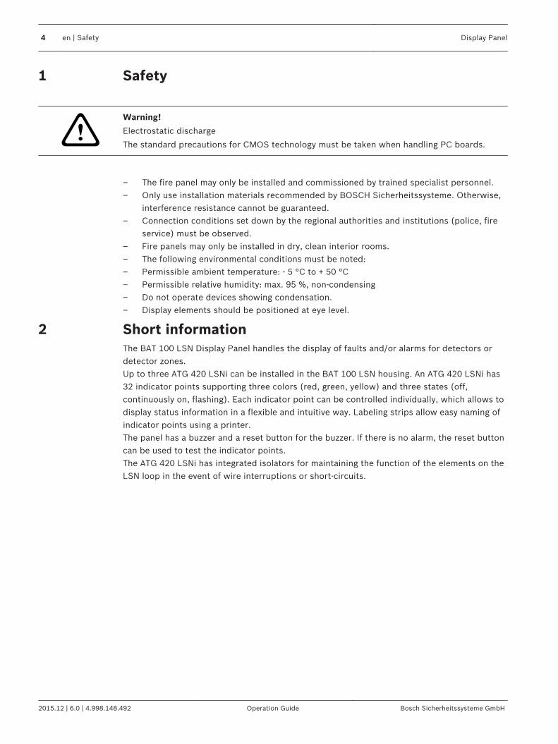
Safety
!Warning!
Electrostatic discharge
The standard precautions for CMOS technology must be taken when handling PC boards.
– The fire panel may only be installed and commissioned by trained specialist personnel.– Only use installation materials recommended by BOSCH Sicherheitssysteme. Otherwise,
interference resistance cannot be guaranteed.– Connection conditions set down by the regional authorities and institutions (police, fire
service) must be observed.– Fire panels may only be installed in dry, clean interior rooms.– The following environmental conditions must be noted:– Permissible ambient temperature: - 5 °C to + 50 °C– Permissible relative humidity: max. 95 %, non-condensing– Do not operate devices showing condensation.– Display elements should be positioned at eye level.
Short informationThe BAT 100 LSN Display Panel handles the display of faults and/or alarms for detectors ordetector zones.Up to three ATG 420 LSNi can be installed in the BAT 100 LSN housing. An ATG 420 LSNi has32 indicator points supporting three colors (red, green, yellow) and three states (off,continuously on, flashing). Each indicator point can be controlled individually, which allows todisplay status information in a flexible and intuitive way. Labeling strips allow easy naming ofindicator points using a printer.The panel has a buzzer and a reset button for the buzzer. If there is no alarm, the reset buttoncan be used to test the indicator points.The ATG 420 LSNi has integrated isolators for maintaining the function of the elements on theLSN loop in the event of wire interruptions or short-circuits.
1
2
4 en | Safety Display Panel
2015.12 | 6.0 | 4.998.148.492 Operation Guide Bosch Sicherheitssysteme GmbH
System overview
BAT 100 LSN
LSN
FMR-5000
FPA-5000
FPA-1200
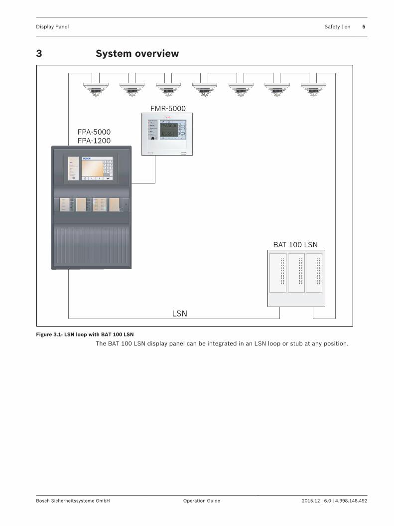
Figure 3.1: LSN loop with BAT 100 LSN
The BAT 100 LSN display panel can be integrated in an LSN loop or stub at any position.
3
Display Panel Safety | en 5
Bosch Sicherheitssysteme GmbH Operation Guide 2015.12 | 6.0 | 4.998.148.492
2
34
1
1
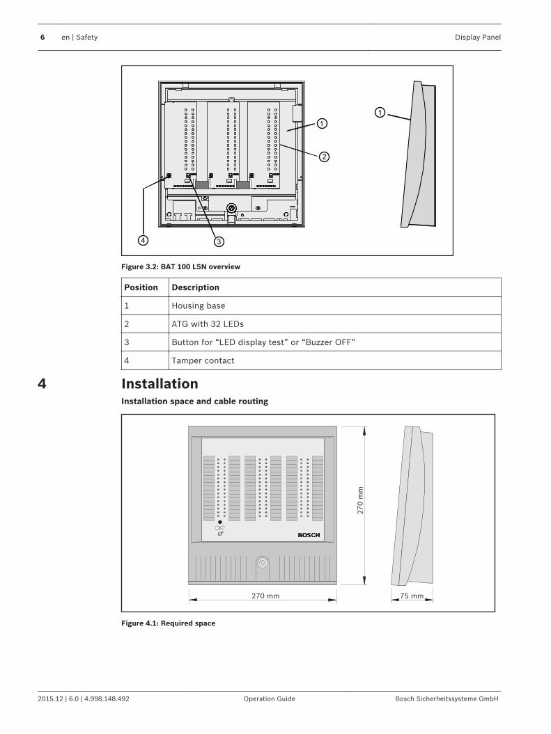
Figure 3.2: BAT 100 LSN overview
Position Description
1 Housing base
2 ATG with 32 LEDs
3 Button for “LED display test” or “Buzzer OFF”
4 Tamper contact
InstallationInstallation space and cable routing
270 mm
270
mm
75 mm
Figure 4.1: Required space
4
6 en | Safety Display Panel
2015.12 | 6.0 | 4.998.148.492 Operation Guide Bosch Sicherheitssysteme GmbH
248 m
m
186 mm
138 mm
69 mm
24 mm
123 mm
21 m
m
3
4 5
2
1
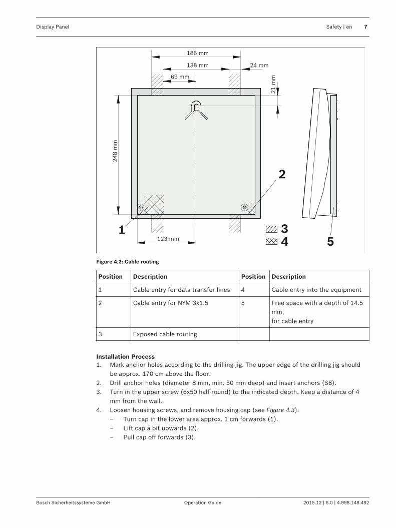
Figure 4.2: Cable routing
Position Description Position Description
1 Cable entry for data transfer lines 4 Cable entry into the equipment
2 Cable entry for NYM 3x1.5 5 Free space with a depth of 14.5mm,for cable entry
3 Exposed cable routing
Installation Process1. Mark anchor holes according to the drilling jig. The upper edge of the drilling jig should
be approx. 170 cm above the floor.2. Drill anchor holes (diameter 8 mm, min. 50 mm deep) and insert anchors (S8).3. Turn in the upper screw (6x50 half-round) to the indicated depth. Keep a distance of 4
mm from the wall.4. Loosen housing screws, and remove housing cap (see Figure 4.3):
– Turn cap in the lower area approx. 1 cm forwards (1).– Lift cap a bit upwards (2).– Pull cap off forwards (3).
Display Panel Safety | en 7
Bosch Sicherheitssysteme GmbH Operation Guide 2015.12 | 6.0 | 4.998.148.492
3
2
1
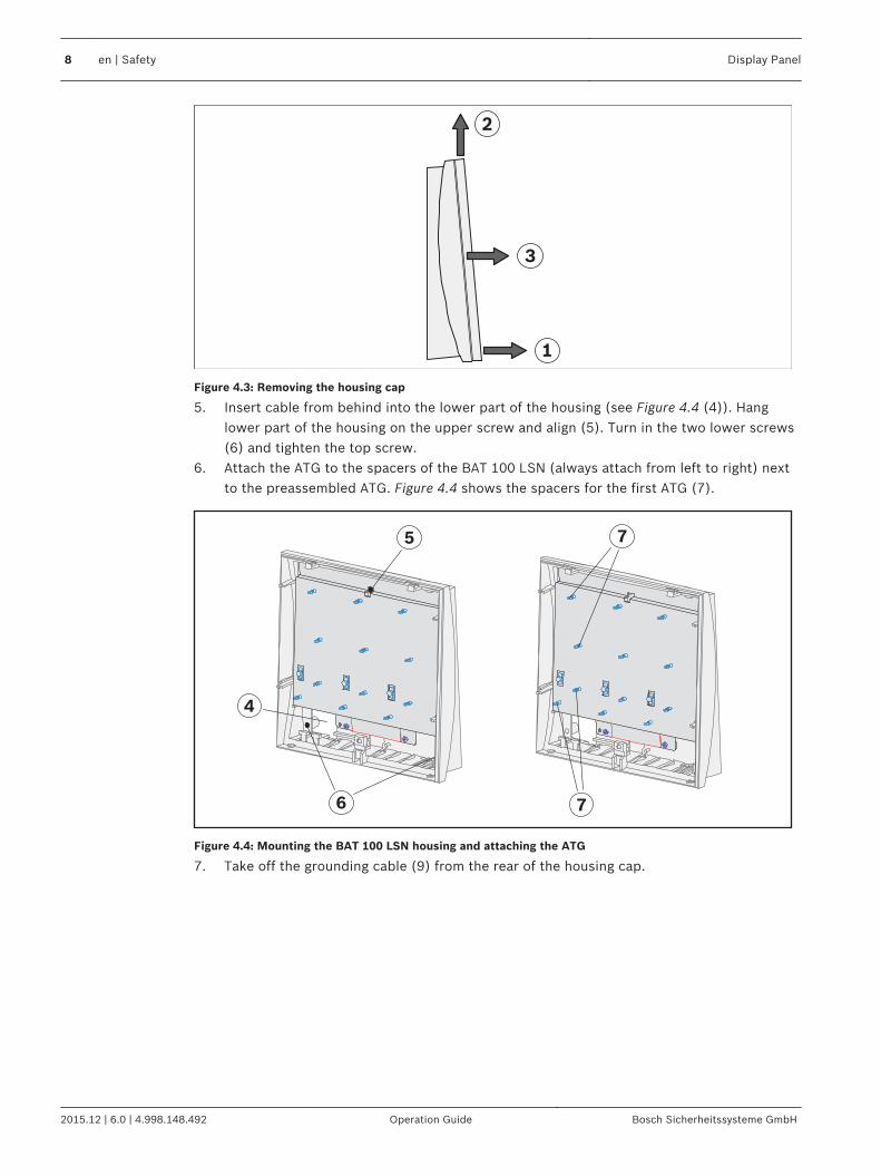
Figure 4.3: Removing the housing cap
5. Insert cable from behind into the lower part of the housing (see Figure 4.4 (4)). Hanglower part of the housing on the upper screw and align (5). Turn in the two lower screws(6) and tighten the top screw.
6. Attach the ATG to the spacers of the BAT 100 LSN (always attach from left to right) nextto the preassembled ATG. Figure 4.4 shows the spacers for the first ATG (7).
7
75
6
4
Figure 4.4: Mounting the BAT 100 LSN housing and attaching the ATG
7. Take off the grounding cable (9) from the rear of the housing cap.
8 en | Safety Display Panel
2015.12 | 6.0 | 4.998.148.492 Operation Guide Bosch Sicherheitssysteme GmbH
U+
V0
1A
US
2A
USATG
2E
TA
1E
TA
9 8
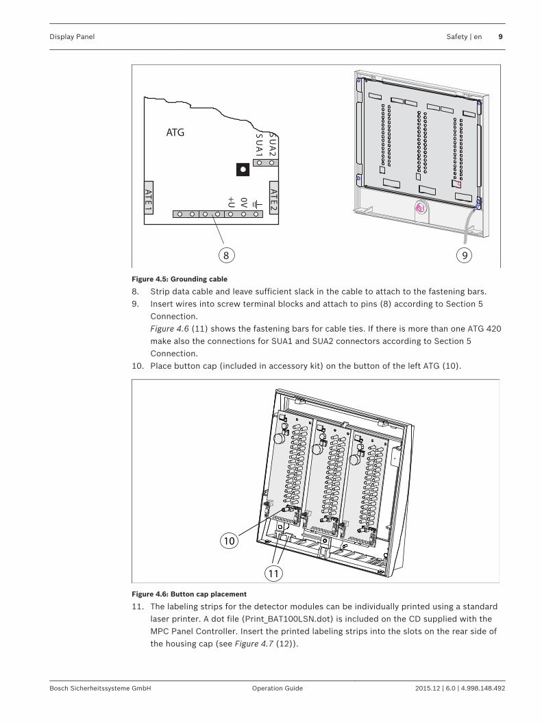
Figure 4.5: Grounding cable
8. Strip data cable and leave sufficient slack in the cable to attach to the fastening bars.9. Insert wires into screw terminal blocks and attach to pins (8) according to Section 5
Connection.Figure 4.6 (11) shows the fastening bars for cable ties. If there is more than one ATG 420make also the connections for SUA1 and SUA2 connectors according to Section 5Connection.
10. Place button cap (included in accessory kit) on the button of the left ATG (10).
11
10
Figure 4.6: Button cap placement
11. The labeling strips for the detector modules can be individually printed using a standardlaser printer. A dot file (Print_BAT100LSN.dot) is included on the CD supplied with theMPC Panel Controller. Insert the printed labeling strips into the slots on the rear side ofthe housing cap (see Figure 4.7 (12)).
Display Panel Safety | en 9
Bosch Sicherheitssysteme GmbH Operation Guide 2015.12 | 6.0 | 4.998.148.492

12
Figure 4.7: Inserting the labeling strips
12. Switch on supply voltage from the control panel. Test the functions of the BAT 100 LSN.13. Attach grounding cable to the rear side of the housing cap (14) (see also Figure 4.5 (9)).14. Replace housing cap:
– Hold cap in the lower area at a slight distance from the lower part of the housing(see Figure 4.8 (14)).
– Replace cap from above (15).– Press cap forwards onto the lower part of the housing (16).
15. Screw together housing.With VdS equipment, turn safety screws into the lower part of the housing from below(17).
LT
16
15
14
18
17
Figure 4.8: Replacing the housing cap and display test
16. Hold down "LT" button for about 5 seconds to start the display test. All LEDs light up inall available colors in a sequence.The BAT 100 LSN is ready for operation.
10 en | Safety Display Panel
2015.12 | 6.0 | 4.998.148.492 Operation Guide Bosch Sicherheitssysteme GmbH
Connection
aLSN1
bLSN1
aLSN2
bLSN2
+U
0V
SUA1
SUA2/0V
GTA .1
ATE2
ATE1
aLSN1
bLSN1
aLSN2
bLSN2
+U
0V
SUA1
SUA2/0V
GTA .2
ATE2
ATE1
aLSN1
bLSN1
aLSN2
bLSN2
+U
0V
SUA1
GTA .3
ATE2
ATE1
rb
hw
rb
hw
wh
ye
bk
rd
aLS
Nb
LS
N+U
0V
aLS
Nb
LS
N+U
0V
ye
wh
SUA2/0V
1
1
3
2
C1
C2
4
4
5
5
Display Panel Safety | en 11
Bosch Sicherheitssysteme GmbH Operation Guide 2015.12 | 6.0 | 4.998.148.492
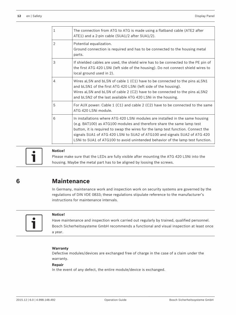
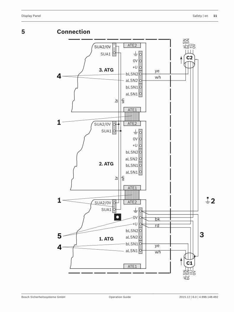
1 The connection from ATG to ATG is made using a flatband cable (ATE2 afterATE1) and a 2‑pin cable (SUA1/2 after SUA1/2).
2 Potential equalization. Ground connection is required and has to be connected to the housing metalparts.
3 If shielded cables are used, the shield wire has to be connected to the PE pin ofthe first ATG 420 LSNi (left side of the housing). Do not connect shield wires tolocal ground used in 2).
4 Wires aLSN and bLSN of cable 1 (C1) have to be connected to the pins aLSN1and bLSN1 of the first ATG 420 LSNi (left side of the housing).Wires aLSN and bLSN of cable 2 (C2) have to be connected to the pins aLSN2and bLSN2 of the last available ATG 420 LSNi in the housing.
5 For AUX power: Cable 1 (C1) and cable 2 (C2) have to be connected to the sameATG 420 LSNi module.
6 In installations where ATG 420 LSNi modules are installed in the same housing(e.g. BAT100) as ATG100 modules and therefore share the same lamp testbutton, it is required to swap the wires for the lamp test function. Connect thesignals SUA1 of ATG 420 LSNi to SUA2 of ATG100 and signals SUA2 of ATG 420LSNi to SUA1 of ATG100 to avoid unintended behavior of the lamp test function.
Notice!
Please make sure that the LEDs are fully visible after mounting the ATG 420 LSNi into the
housing. Maybe the metal part has to be aligned by loosing the screws.
MaintenanceIn Germany, maintenance work and inspection work on security systems are governed by theregulations of DIN VDE 0833; these regulations stipulate reference to the manufacturer’sinstructions for maintenance intervals.
Notice!
Have maintenance and inspection work carried out regularly by trained, qualified personnel.
Bosch Sicherheitssysteme GmbH recommends a functional and visual inspection at least once
a year.
WarrantyDefective modules/devices are exchanged free of charge in the case of a claim under thewarranty.
RepairIn the event of any defect, the entire module/device is exchanged.
6
12 en | Safety Display Panel
2015.12 | 6.0 | 4.998.148.492 Operation Guide Bosch Sicherheitssysteme GmbH
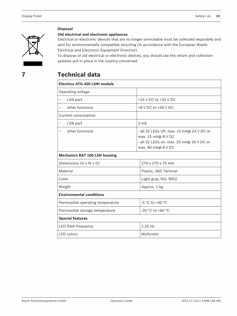
Disposal
Old electrical and electronic appliancesElectrical or electronic devices that are no longer serviceable must be collected separately andsent for environmentally compatible recycling (in accordance with the European WasteElectrical and Electronic Equipment Directive).To dispose of old electrical or electronic devices, you should use the return and collectionsystems put in place in the country concerned.
Technical dataElectrics ATG 420 LSNi module
Operating voltage
– LSN part +15 V DC to +33 V DC
– other functions +8 V DC to +30 V DC
Current consumption
– LSN part 3 mA
– other functions - all 32 LEDs off: max. 10 mA@ 24 V DC ormax. 15 mA@ 8 V DC- all 32 LEDs on: max. 25 mA@ 24 V DC ormax. 60 mA@ 8 V DC
Mechanics BAT 100 LSN housing
Dimensions (H x W x D) 270 x 270 x 75 mm
Material Plastic, ABS Terluran
Color Light gray, RAL 9002
Weight Approx. 1 kg
Environmental conditions
Permissible operating temperature -5 °C to +50 °C
Permissible storage temperature -20 °C to +60 °C
Special features
LED flash frequency 1.25 Hz
LED colors Multicolor
7
Display Panel Safety | en 13
Bosch Sicherheitssysteme GmbH Operation Guide 2015.12 | 6.0 | 4.998.148.492


Bosch Sicherheitssysteme GmbHRobert-Bosch-Ring 585630 GrasbrunnGermanywww.boschsecurity.com© Bosch Sicherheitssysteme GmbH, 2015