Embed Size (px)
Citation preview
www.ipdatatel.com
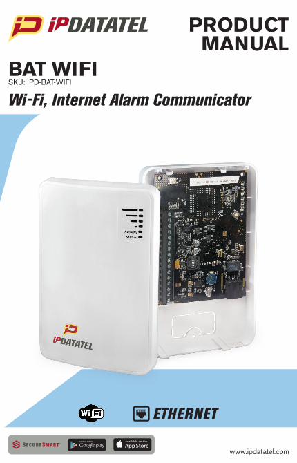
PRODUCT MANUAL
BAT WIFISKU: IPD-BAT-WIFI
Wi-Fi, Internet Alarm Communicator
Universal WiFi BAT Installation Guide (rev 2.0) 2
Technical Support Information For Technical Support, call toll free: 866-896-1818 Email us at [email protected] Visit www.ipdatatel.com ipDatatel Technical Support 13110 Southwest Freeway Sugar Land, TX 77478
Revision Notes Revision Notes Date
1 Initial Release 8/8/2014
2 Updated WiFi Joining Process 1/13/2015
Universal WiFi BAT Installation Guide (rev 2.0) 3
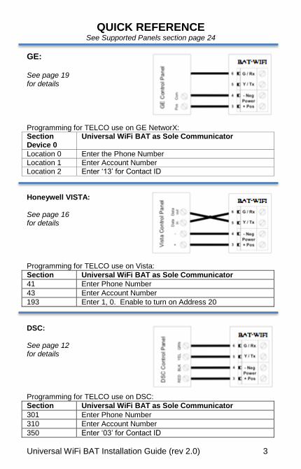
QUICK REFERENCE See Supported Panels section page 24
GE:
See page 19 for details
Programming for TELCO use on GE NetworX: Section Device 0
Universal WiFi BAT as Sole Communicator
Location 0 Enter the Phone Number
Location 1 Enter Account Number Location 2 Enter ‘13’ for Contact ID
Honeywell VISTA: See page 16 for details Programming for TELCO use on Vista:
Section Universal WiFi BAT as Sole Communicator
41 Enter Phone Number
43 Enter Account Number
193 Enter 1, 0. Enable to turn on Address 20
DSC: See page 12 for details Programming for TELCO use on DSC:
Section Universal WiFi BAT as Sole Communicator
301 Enter Phone Number
310 Enter Account Number
350 Enter ‘03’ for Contact ID
Universal WiFi BAT Installation Guide (rev 2.0) 4
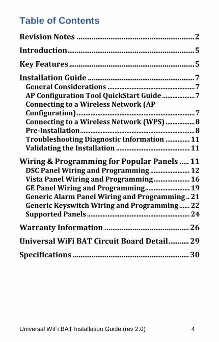
Table of Contents
Revision Notes ............................................................... 2
Introduction .................................................................... 5
Key Features ................................................................... 5
Installation Guide ......................................................... 7 General Considerations ................................................... 7 AP Configuration Tool QuickStart Guide ................... 7 Connecting to a Wireless Network (AP Configuration) ..................................................................... 7 Connecting to a Wireless Network (WPS) ................. 8 Pre-Installation ................................................................... 8 Troubleshooting Diagnostic Information .............. 11 Validating the Installation ........................................... 11
Wiring & Programming for Popular Panels ..... 11 DSC Panel Wiring and Programming ....................... 12 Vista Panel Wiring and Programming ..................... 16 GE Panel Wiring and Programming .......................... 19 Generic Alarm Panel Wiring and Programming .. 21 Generic Keyswitch Wiring and Programming ...... 22 Supported Panels ............................................................ 24
Warranty Information ............................................. 26
Universal WiFi BAT Circuit Board Detail ........... 29
Specifications .............................................................. 30
Universal WiFi BAT Installation Guide (rev 2.0) 5
Introduction ipDatatel’s Universal WIFI Broadband Alarm Transceiver (BAT-WIFI) is a multi-path wireless and wired internet connected alarm panel transceiver. The BAT-WIFI transmits alarms over broadband Internet via hardwired RJ45 Ethernet connection or via WIFI wireless networks. The Bat-WIFI is compatible with any alarm control panel that transmits Contact ID (CID) format from its digital dialer. The BAT-WIFI also connects to the Keypad Bus of compatible (Honeywell, DSC and GE) alarm control panels to provide additional interactive services. The end user has virtual keypad access via smartphone and the web, as well as alarm monitoring notifications via push/text, email, and computerized voice call. ipDatatel’s proprietary uDownloader software enables remote management of Honeywell and DSC alarm panels that are connected to the BAT-WIFI.
Key Features Broadband Hardwired and WiFi Communicator
The BAT-WIFI replaces outdated conventional phone lines to provide high-speed IP alarm monitoring transmissions over the Internet. Remote Universal Downloader
ipDatatel’s Universal Downloader software, uDownloader, enables remote management of alarm panels that are connected to ipDatatel’s BAT products via the Internet uDownloader currently supports Honeywell Compass and DSC DLS 5. ipDatatel’s uDownloader software is available for download at www.alarmdealer.com in the Dealer Resources section.
Universal WiFi BAT Installation Guide (rev 2.0) 6
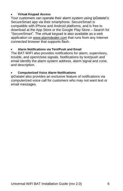
Virtual Keypad Access
Your customers can operate their alarm system using ipDatatel’s SecureSmart app via their smartphone. SecureSmart is compatible with iPhone and Android platforms, and is free to download at the App Store or the Google Play Store – Search for “SecureSmart”. The virtual keypad is also available as a web application on www.alarmdealer.com that runs from any Internet connected browser that supports flash. Alarm Notifications via Text/Push and Email
The BAT-WIFI also provides notifications for alarm, supervisory, trouble, and open/close signals. Notifications by text/push and email identify the alarm system address, alarm signal and zone, and description. Computerized Voice Alarm Notifications
ipDatatel also provides an exclusive feature of notifications via computerized voice call for customers who may not want text or email messages.
Universal WiFi BAT Installation Guide (rev 2.0) 7
Installation Guide
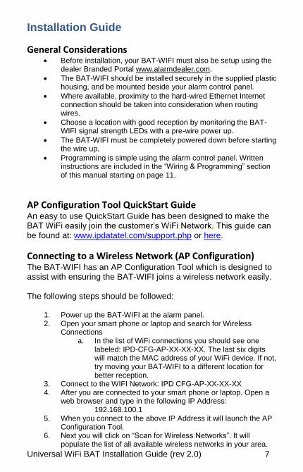
General Considerations Before installation, your BAT-WIFI must also be setup using the
dealer Branded Portal www.alarmdealer.com.
The BAT-WIFI should be installed securely in the supplied plastic housing, and be mounted beside your alarm control panel.
Where available, proximity to the hard-wired Ethernet Internet connection should be taken into consideration when routing wires.
Choose a location with good reception by monitoring the BAT-WIFI signal strength LEDs with a pre-wire power up.
The BAT-WIFI must be completely powered down before starting the wire up.
Programming is simple using the alarm control panel. Written instructions are included in the “Wiring & Programming” section of this manual starting on page 11.
AP Configuration Tool QuickStart Guide An easy to use QuickStart Guide has been designed to make the BAT WiFi easily join the customer’s WiFi Network. This guide can be found at: www.ipdatatel.com/support.php or here.
Connecting to a Wireless Network (AP Configuration) The BAT-WIFI has an AP Configuration Tool which is designed to assist with ensuring the BAT-WIFI joins a wireless network easily. The following steps should be followed:
1. Power up the BAT-WIFI at the alarm panel. 2. Open your smart phone or laptop and search for Wireless
Connections a. In the list of WiFi connections you should see one
labeled: IPD-CFG-AP-XX-XX-XX. The last six digits will match the MAC address of your WiFi device. If not, try moving your BAT-WIFI to a different location for better reception.
3. Connect to the WIFI Network: IPD CFG-AP-XX-XX-XX 4. After you are connected to your smart phone or laptop. Open a
web browser and type in the following IP Address: 192.168.100.1
5. When you connect to the above IP Address it will launch the AP Configuration Tool.
6. Next you will click on “Scan for Wireless Networks”. It will populate the list of all available wireless networks in your area.
Universal WiFi BAT Installation Guide (rev 2.0) 8
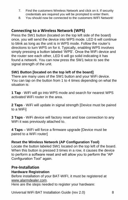
7. Find the customers Wireless Network and click on it. If security credentials are required you will be prompted to enter them.
8. You should now be connected to the customers WIFI Network!
Connecting to a Wireless Network (WPS) Press the SW1 button (located on the top left side of the board) once, you will send the device into WPS mode. LED 6 will continue to blink as long as the unit is in WPS mode. Follow the router’s directions to turn WPS on for it. Typically, enabling WPS involves simply pressing a button labeled ‘WPS’. Once the WiFi device and the router see each other, LED 6 will go solid indicating it has found a network. You can now press the SW1 twice to see the signal strength of the unit. SW1 Button [located on the top left of the board]
There are many uses of the SW1 button and your WiFi device. You can tap on the button from 1 to 4 times depending on what the situation is: 1 Tap - WiFi will go into WPS mode and search for nearest WPS
activated WiFi router in the area. 2 Taps - WiFi will update in signal strength [Device must be paired
to a WiFi] 3 Taps - WiFi device will factory reset and lose connection to any
WiFi it was previously attached to. 4 Taps – WiFi will force a firmware upgrade [Device must be
paired to a WiFi router] Reset the Wireless Network (AP Configuration Tool)
Locate the button labeled SW1 located on the top left of the board. When this button is pressed 3 times in a row, it causes the device to perform a software reset and will allow you to perform the “AP Configuration Tool” again.
Pre-Installation Hardware Registration
Before installation of your BAT-WIFI, it must be registered at www.alarmdealer.com. Here are the steps needed to register your hardware:
Universal WiFi BAT Installation Guide (rev 2.0) 9
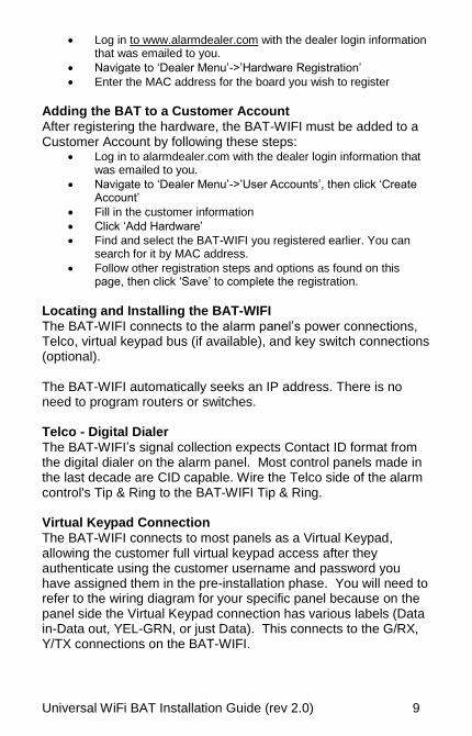
Log in to www.alarmdealer.com with the dealer login information that was emailed to you.
Navigate to ‘Dealer Menu’->’Hardware Registration’
Enter the MAC address for the board you wish to register
Adding the BAT to a Customer Account
After registering the hardware, the BAT-WIFI must be added to a Customer Account by following these steps:
Log in to alarmdealer.com with the dealer login information that was emailed to you.
Navigate to ‘Dealer Menu’->’User Accounts’, then click ‘Create Account’
Fill in the customer information
Click ‘Add Hardware’
Find and select the BAT-WIFI you registered earlier. You can search for it by MAC address.
Follow other registration steps and options as found on this page, then click ‘Save’ to complete the registration.
Locating and Installing the BAT-WIFI
The BAT-WIFI connects to the alarm panel’s power connections, Telco, virtual keypad bus (if available), and key switch connections (optional). The BAT-WIFI automatically seeks an IP address. There is no need to program routers or switches. Telco - Digital Dialer
The BAT-WIFI’s signal collection expects Contact ID format from the digital dialer on the alarm panel. Most control panels made in the last decade are CID capable. Wire the Telco side of the alarm control's Tip & Ring to the BAT-WIFI Tip & Ring. Virtual Keypad Connection
The BAT-WIFI connects to most panels as a Virtual Keypad, allowing the customer full virtual keypad access after they authenticate using the customer username and password you have assigned them in the pre-installation phase. You will need to refer to the wiring diagram for your specific panel because on the panel side the Virtual Keypad connection has various labels (Data in-Data out, YEL-GRN, or just Data). This connects to the G/RX, Y/TX connections on the BAT-WIFI.
Universal WiFi BAT Installation Guide (rev 2.0) 10
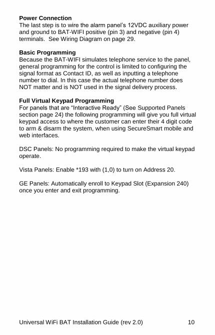
Power Connection
The last step is to wire the alarm panel’s 12VDC auxiliary power and ground to BAT-WIFI positive (pin 3) and negative (pin 4) terminals. See Wiring Diagram on page 29. Basic Programming
Because the BAT-WIFI simulates telephone service to the panel, general programming for the control is limited to configuring the signal format as Contact ID, as well as inputting a telephone number to dial. In this case the actual telephone number does NOT matter and is NOT used in the signal delivery process. Full Virtual Keypad Programming
For panels that are “Interactive Ready” (See Supported Panels section page 24) the following programming will give you full virtual keypad access to where the customer can enter their 4 digit code to arm & disarm the system, when using SecureSmart mobile and web interfaces. DSC Panels: No programming required to make the virtual keypad operate. Vista Panels: Enable *193 with (1,0) to turn on Address 20. GE Panels: Automatically enroll to Keypad Slot (Expansion 240) once you enter and exit programming.
Universal WiFi BAT Installation Guide (rev 2.0) 11
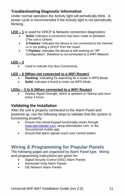
Troubleshooting Diagnostic Information Under normal operation the Activity light will periodically blink. A power cycle is recommended if the Activity light is not periodically blinking. LED – 1 is used for DHCP & Network connection diagnostics:
Solid: Indicates a connection has been made to ipDatatel. (The unit is Online)
3 Flashes: Indicates the device is not connected to the Internet or is not pulling a DHCP from the router.
7 Flashes: Indicates the device is still working on “AP Configuration”, therefore is not connected to a WIFI Network.
LED – 2
Used to indicate Key Bus Connectivity.
LED – 6 (When not connected to a WiFi Router)
Flashing: Indicating it’s searching for a router in WPS Mode.
Solid: Indicates it found a router via WPS Mode.
LEDs – 3 to 6 (When connected to a WiFi Router)
Display Signal Strength, which is updated on Startup and once every 4 hours.
Validating the Installation After the unit is properly connected to the Alarm Panel and powered up, use the following steps to validate that the system is functioning properly:
Ensure that virtual keypad functionality works through www.alarmdealer.com, setup.alarmdealer.com, or the SecureSmart mobile app.
Ensure that alarm signals reach your central station.
Wiring & Programming for Popular Panels The following pages are organized by Alarm Panel type. Wiring and programming instructions are given for:
Digital Security Control (DSC) Alarm Panels
Honeywell Vista Alarm Panels
GE NetworX Alarm Panels
Universal WiFi BAT Installation Guide (rev 2.0) 12
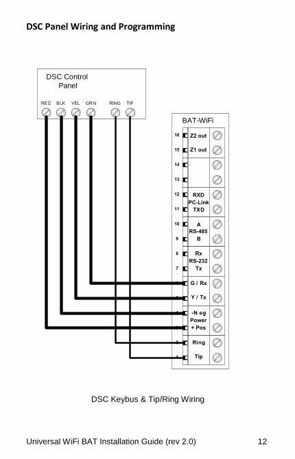
DSC Panel Wiring and Programming
DSC Keybus & Tip/Ring Wiring
RING TIP RE D B LK YEL GR N
D S C Co nt rol Panel
1
2
3
4
5
6
7
8
9
10
11
12
13
14
15
16
Tip
Ri n g
+ Pos
-N e g
Y / Tx
G / Rx
Tx
Rx
B
A
TX D
RXD
Z1 out
Z2 out
RS-232
RS-485
PC-Link
Power
BAT-WiFi
Universal WiFi BAT Installation Guide (rev 2.0) 13
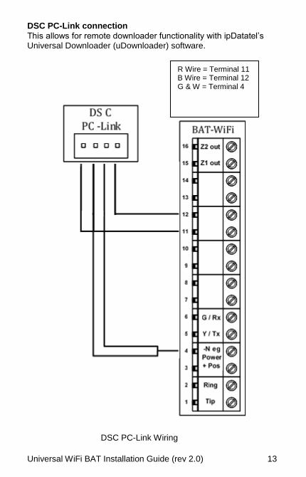
DSC PC-Link connection
This allows for remote downloader functionality with ipDatatel’s Universal Downloader (uDownloader) software.
DSC PC-Link Wiring
R Wire = Terminal 11 B Wire = Terminal 12 G & W = Terminal 4
Universal WiFi BAT Installation Guide (rev 2.0) 14
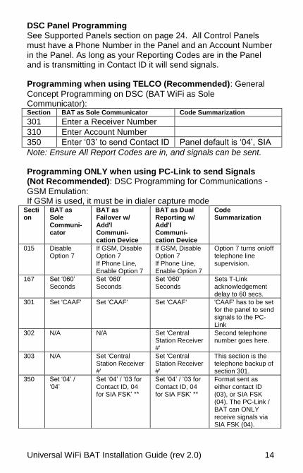
DSC Panel Programming
See Supported Panels section on page 24. All Control Panels must have a Phone Number in the Panel and an Account Number in the Panel. As long as your Reporting Codes are in the Panel and is transmitting in Contact ID it will send signals. Programming when using TELCO (Recommended): General
Concept Programming on DSC (BAT WiFi as Sole Communicator): Section BAT as Sole Communicator Code Summarization
301 Enter a Receiver Number
310 Enter Account Number
350 Enter ‘03’ to send Contact ID Panel default is ‘04’, SIA
Note: Ensure All Report Codes are in, and signals can be sent. Programming ONLY when using PC-Link to send Signals (Not Recommended): DSC Programming for Communications -
GSM Emulation: If GSM is used, it must be in dialer capture mode
Section
BAT as Sole Communi-cator
BAT as Failover w/ Add'l Communi-cation Device
BAT as Dual Reporting w/ Add'l Communi-cation Device
Code Summarization
015 Disable Option 7
If GSM, Disable Option 7 If Phone Line, Enable Option 7
If GSM, Disable Option 7 If Phone Line, Enable Option 7
Option 7 turns on/off telephone line supervision.
167 Set ‘060’ Seconds
Set ‘060’ Seconds
Set ‘060’ Seconds
Sets T-Link acknowledgement delay to 60 secs.
301 Set 'CAAF' Set 'CAAF' Set 'CAAF' 'CAAF' has to be set for the panel to send signals to the PC-Link
302 N/A N/A Set 'Central Station Receiver #'
Second telephone number goes here.
303 N/A Set 'Central Station Receiver #'
Set 'Central Station Receiver #'
This section is the telephone backup of section 301.
350 Set ‘04’ / ‘04’
Set ‘04’ / ’03 for Contact ID, 04 for SIA FSK’ **
Set ‘04’ / ’03 for Contact ID, 04 for SIA FSK’ **
Format sent as either contact ID (03), or SIA FSK (04). The PC-Link / BAT can ONLY receive signals via SIA FSK (04).
Universal WiFi BAT Installation Guide (rev 2.0) 15
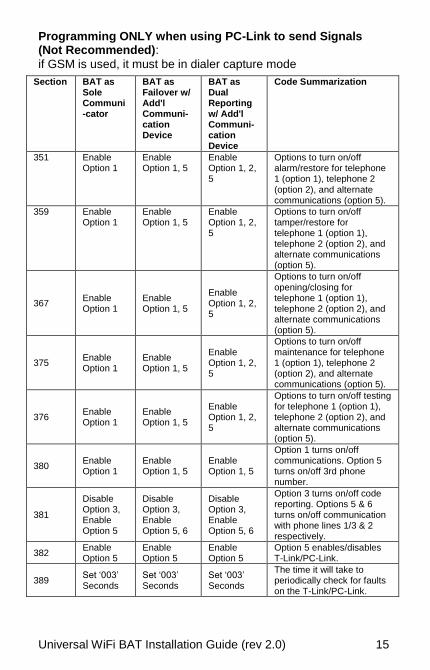
Programming ONLY when using PC-Link to send Signals (Not Recommended):
if GSM is used, it must be in dialer capture mode
Section BAT as Sole Communi-cator
BAT as Failover w/ Add'l Communi-cation Device
BAT as Dual Reporting w/ Add'l Communi-cation Device
Code Summarization
351 Enable Option 1
Enable Option 1, 5
Enable Option 1, 2, 5
Options to turn on/off alarm/restore for telephone 1 (option 1), telephone 2 (option 2), and alternate communications (option 5).
359 Enable Option 1
Enable Option 1, 5
Enable Option 1, 2, 5
Options to turn on/off tamper/restore for telephone 1 (option 1), telephone 2 (option 2), and alternate communications (option 5).
367 Enable Option 1
Enable Option 1, 5
Enable Option 1, 2, 5
Options to turn on/off opening/closing for telephone 1 (option 1), telephone 2 (option 2), and alternate communications (option 5).
375 Enable Option 1
Enable Option 1, 5
Enable Option 1, 2, 5
Options to turn on/off maintenance for telephone 1 (option 1), telephone 2 (option 2), and alternate communications (option 5).
376 Enable Option 1
Enable Option 1, 5
Enable Option 1, 2, 5
Options to turn on/off testing for telephone 1 (option 1), telephone 2 (option 2), and alternate communications (option 5).
380 Enable Option 1
Enable Option 1, 5
Enable Option 1, 5
Option 1 turns on/off communications. Option 5 turns on/off 3rd phone number.
381
Disable Option 3, Enable Option 5
Disable Option 3, Enable Option 5, 6
Disable Option 3, Enable Option 5, 6
Option 3 turns on/off code reporting. Options 5 & 6 turns on/off communication with phone lines 1/3 & 2 respectively.
382 Enable Option 5
Enable Option 5
Enable Option 5
Option 5 enables/disables T-Link/PC-Link.
389 Set ‘003’ Seconds
Set ‘003’ Seconds
Set ‘003’ Seconds
The time it will take to periodically check for faults on the T-Link/PC-Link.
Universal WiFi BAT Installation Guide (rev 2.0) 16
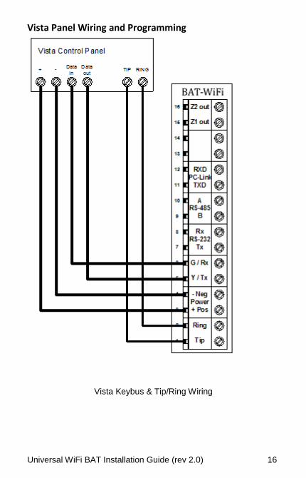
Vista Panel Wiring and Programming
Vista Keybus & Tip/Ring Wiring
Universal WiFi BAT Installation Guide (rev 2.0) 17
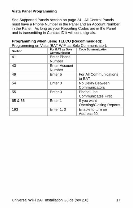
Vista Panel Programming
See Supported Panels section on page 24. All Control Panels must have a Phone Number in the Panel and an Account Number in the Panel. As long as your Reporting Codes are in the Panel and is transmitting in Contact ID it will send signals. Programming when using TELCO (Recommended):
Programming on Vista (BAT WiFi as Sole Communicator):
Section For BAT as Sole Communicator
Code Summarization
41 Enter Phone Number
43 Enter Account Number
49 Enter 5 For All Communications to BAT
54 Enter 0 No Delay Between Communicators
55 Enter 0 Phone Line Communicates First
65 & 66 Enter 1 If you want Opening/Closing Reports
193 Enter 1, 0 Enable to turn on Address 20
Universal WiFi BAT Installation Guide (rev 2.0) 18
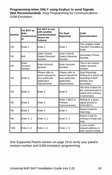
Programming when ONLY using Keybus to send Signals (Not Recommended): Vista Programming for Communications -
GSM Emulation:
See Supported Panels section on page 24 to verify your panel’s revision number and GSM emulation programming.
Section
For BAT as Sole Communicator
For BAT in use with another Communication Device for Failover
For Dual Reporting
Code Summarization
*29 Enter 1 Enter 1 Enter 1 This enables GSM. The BAT Emulates a GSM.
*42 N/A Enter Central Station Receiver Number
Enter Central Station Receiver Number
Secondary Phone Number
*43 Enter Account Number
Enter Account Number
Enter Account Number
This is the central station account number
*49 Enter 5
Please refer to panel manual for your particular application requirements
Please refer to panel manual for your particular application requirements
Dual Reporting; Setting to 5 sends all reporting to both primary and secondary.
*54 Enter 0 Enter 2 Enter 0
The time it takes for the communicator to switch from primary to secondary.
*55 Enter 1 Enter 1 Enter 1 (BAT is Primary Communicator)
Setting to 1 gives signal priority to GSM (BAT).
*65 Enter 1 Enter 1 Enter 1 Report Code for Openings.
*66 Enter 1, 1 Enter 1, 1 Enter 1, 1 Report Code for Arming in Away and Stay.
*193 Enter 1, 0 Enter 1, 0 Enter 1, 0 1 turns on/off keypad address. 0 sets sound to beep.
Universal WiFi BAT Installation Guide (rev 2.0) 19
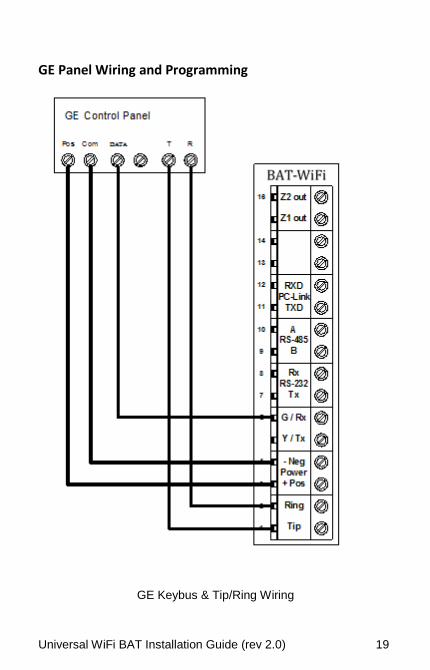
GE Panel Wiring and Programming
GE Keybus & Tip/Ring Wiring
Universal WiFi BAT Installation Guide (rev 2.0) 20
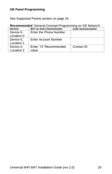
GE Panel Programming
See Supported Panels section on page 24. Recommended: General Concept Programming on GE NetworX: Section BAT as Sole Communicator Code Summarization Device 0, Location 0
Enter the Phone Number
Device 0, Location 1
Enter Account Number
Device 0, Location 2
Enter ‘13’ Recommended value
Contact ID
Universal WiFi BAT Installation Guide (rev 2.0) 21
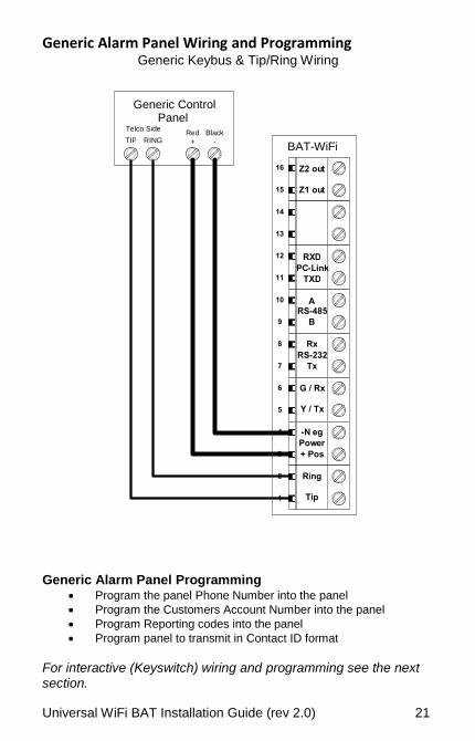
Generic Alarm Panel Wiring and Programming Generic Keybus & Tip/Ring Wiring
Generic Alarm Panel Programming
Program the panel Phone Number into the panel
Program the Customers Account Number into the panel
Program Reporting codes into the panel
Program panel to transmit in Contact ID format
For interactive (Keyswitch) wiring and programming see the next section.
Generic Control Panel
TIP R ING Re d
+ Bl ac k
-
1
2
3
4
5
6
7
8
9
10
11
12
13
14
15
16
Ti p
Ri ng
+ Pos
-N e g
Y / Tx
G / Rx
Tx
Rx
B
A
TXD
RX D
Z1 ou t
Z2 ou t
RS-232
RS-485
PC - L ink
Pow e r
BAT-WiFi
Te l c o Side
Universal WiFi BAT Installation Guide (rev 2.0) 22
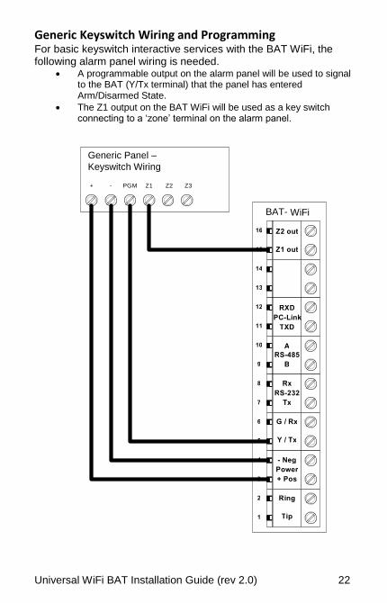
Generic Keyswitch Wiring and Programming For basic keyswitch interactive services with the BAT WiFi, the following alarm panel wiring is needed.
A programmable output on the alarm panel will be used to signal to the BAT (Y/Tx terminal) that the panel has entered Arm/Disarmed State.
The Z1 output on the BAT WiFi will be used as a key switch connecting to a ‘zone’ terminal on the alarm panel.
1
2
3
4
5
6
7
8
9
1 0
1 1
1 2
1 3
1 4
1 5
1 6
T i p
R i n g
+ P o s
- N e g
Y / T x
G / R x
T x
R x
B
A
T X D
R X D
Z 1 o u t
Z 2 o u t
R S - 2 3 2
R S - 4 8 5
P C - L i n k
P o w e r
B A T - WiFi
+ - P G M Z 1
G e n e r i c P a n e l – K e y s w i t c h W i r i n g
Z 2 Z 3
Universal WiFi BAT Installation Guide (rev 2.0) 23
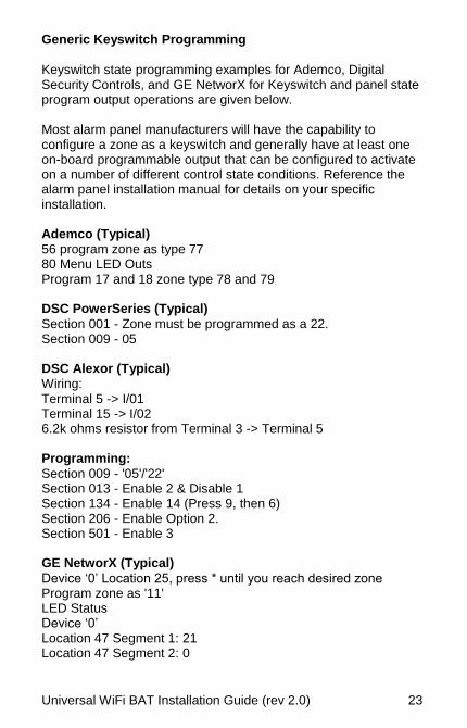
Generic Keyswitch Programming
Keyswitch state programming examples for Ademco, Digital Security Controls, and GE NetworX for Keyswitch and panel state program output operations are given below. Most alarm panel manufacturers will have the capability to configure a zone as a keyswitch and generally have at least one on-board programmable output that can be configured to activate on a number of different control state conditions. Reference the alarm panel installation manual for details on your specific installation. Ademco (Typical)
56 program zone as type 77 80 Menu LED Outs Program 17 and 18 zone type 78 and 79 DSC PowerSeries (Typical)
Section 001 - Zone must be programmed as a 22. Section 009 - 05 DSC Alexor (Typical)
Wiring: Terminal 5 -> I/01 Terminal 15 -> I/02 6.2k ohms resistor from Terminal 3 -> Terminal 5 Programming:
Section 009 - '05'/'22' Section 013 - Enable 2 & Disable 1 Section 134 - Enable 14 (Press 9, then 6) Section 206 - Enable Option 2. Section 501 - Enable 3 GE NetworX (Typical)
Device ‘0’ Location 25, press * until you reach desired zone Program zone as '11' LED Status Device ‘0’ Location 47 Segment 1: 21 Location 47 Segment 2: 0
Universal WiFi BAT Installation Guide (rev 2.0) 24
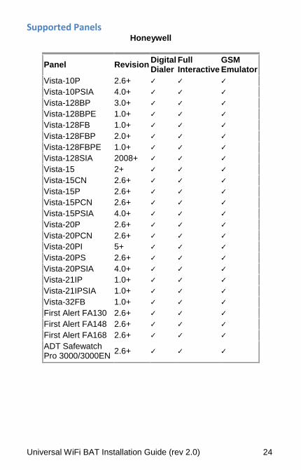
Supported Panels Honeywell
Panel Revision Digital Dialer
Full Interactive
GSM Emulator
Vista-10P 2.6+ ✓ ✓ ✓
Vista-10PSIA 4.0+ ✓ ✓ ✓
Vista-128BP 3.0+ ✓ ✓ ✓
Vista-128BPE 1.0+ ✓ ✓ ✓
Vista-128FB 1.0+ ✓ ✓ ✓
Vista-128FBP 2.0+ ✓ ✓ ✓
Vista-128FBPE 1.0+ ✓ ✓ ✓
Vista-128SIA 2008+ ✓ ✓ ✓
Vista-15 2+ ✓ ✓ ✓
Vista-15CN 2.6+ ✓ ✓ ✓
Vista-15P 2.6+ ✓ ✓ ✓
Vista-15PCN 2.6+ ✓ ✓ ✓
Vista-15PSIA 4.0+ ✓ ✓ ✓
Vista-20P 2.6+ ✓ ✓ ✓
Vista-20PCN 2.6+ ✓ ✓ ✓
Vista-20PI 5+ ✓ ✓ ✓
Vista-20PS 2.6+ ✓ ✓ ✓
Vista-20PSIA 4.0+ ✓ ✓ ✓
Vista-21IP 1.0+ ✓ ✓ ✓
Vista-21IPSIA 1.0+ ✓ ✓ ✓
Vista-32FB 1.0+ ✓ ✓ ✓
First Alert FA130 2.6+ ✓ ✓ ✓
First Alert FA148 2.6+ ✓ ✓ ✓
First Alert FA168 2.6+ ✓ ✓ ✓
ADT Safewatch Pro 3000/3000EN
2.6+ ✓ ✓ ✓
Universal WiFi BAT Installation Guide (rev 2.0) 25
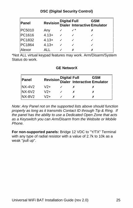
DSC (Digital Security Control)
Panel Revision Digital Dialer
Full Interactive
GSM Emulator
PC5010 Any ✓ ✓ * ✗
PC1616 4.13+ ✓ ✓ ✓
PC1832 4.13+ ✓ ✓ ✓
PC1864 4.13+ ✓ ✓ ✓
Alexor ALL ✓ ✗ ✗
*Not ALL virtual keypad features may work. Arm/Disarm/System Status do work.
GE NetworX
Panel Revision Digital Dialer
Full Interactive
GSM Emulator
NX-4V2 V2+ ✓ ✗ ✗
NX-6V2 V2+ ✓ ✗ ✗
NX-8V2 V2+ ✓ ✗ ✗
Note: Any Panel not on the supported lists above should function properly as long as it transmits Contact ID through Tip & Ring. If the panel has the ability to use a Dedicated Open Zone that acts as a Keyswitch you can Arm/Disarm from the Website or Mobile Phone. For non-supported panels: Bridge 12 VDC to "Y/TX" Terminal
with any type of radial resistor with a value of 2.7k to 10k as a weak "pull up".
Universal WiFi BAT Installation Guide (rev 2.0) 26
Warranty Information LIMITED WARRANTY
ipDatatel, LLC (hereinafter referred to as “Seller”), Located at 13110 Southwest Freeway, Sugar Land Texas 77478, warrants its product to be in conformance with the product specification, and to be free from defects in materials and workmanship under normal use and service for a period of twelve (12) months from the date of original purchase. Seller’s sole obligation shall be limited to repairing or replacing, at its option, free of charge for materials or labor, any product which is proved not to be within Seller’s specifications of the Product, or proves defective in materials or workmanship under normal use and service. Any device purchased which is enclosed within a plastic case must remain in the plastic case for installation and regular use after installation. At no point should the device be removed and mounted without the plastic case, in doing so you may void the device warranty. LIMITED LIABILITY
Seller shall have no liability or obligation under this Limited Warranty or otherwise for merchantability or fitness for any particular use; nor shall it extend its Limited Warranty, if the product is altered, or improperly installed, repaired, or serviced. There are no warranties, express or implied, that extend beyond those contained within this document. In no case shall Seller be liable to person or entity for any consequential, or any other basis of law or liability whatsoever, whether or not such loss or damage is caused by Seller’s own negligence or fault. Seller does not represent that the Product may be compromised or circumvented, or that it will provide the service intended; or that the Product will prevent any personal injury or property loss by burglary, robbery, or otherwise; or that the Product in all cases will provide adequate warning or detection. Customer understands that a properly installed and maintained alarm system may only reduce the risk of burglary, robbery, or other such events occurring without providing an alarm, but is not insurance or guarantee that such will not occur or that there will be no personal injury or property loss as a result.
Universal WiFi BAT Installation Guide (rev 2.0) 27
Consequently, Seller shall have no liability for any personal injury, property damage or any other loss based on a claim that the Product or services there from, failed to give warning. However, if seller is held liable, directly or indirectly, for any loss or damage arising under this Limited Warranty or otherwise regardless of cause or origin, Seller maximum liability shall not in any case exceed the purchase price of the Product, which shall be the complete and exclusive remedy against Seller. This Limited Warranty replaces any previous warranty, and is the only warranty made by Seller for this Product. No increase or alteration, written or verbal.
FCC and Industry Canada Regulatory Compliance FCC Warning / IC Statement
This device complies with Part 15 of the FCC Rules and with ICES-003, Issue 4 of Industry Canada. Operation is subject to the following two conditions: (1) This device may not cause harmful interference, and (2) This device must accept any interference received, including interference that may cause undesired operation. Note: This equipment has been tested and found to comply with
the limits for a Class B digital device, pursuant to Part 15 of the FCC Rules. These limits are designed to provide reasonable protection against harmful interference in a residential installation. This equipment generates, uses and can radiate radio frequency energy and, if not installed and used in accordance with the instructions, may cause harmful interference to radio communications. However, there is no guarantee that interference will not occur in a particular installation. If this equipment does cause harmful interference to radio or television reception, which can be determined by turning the equipment off and on, the user is encouraged to try to correct the interference by one or more of the following measures: • Reorient or relocate the receiving antenna. • Increase the separation between the equipment and receiver. • Connect the equipment into an outlet on a circuit different from that to which the receiver is connected. • Consult the dealer or an experienced radio/TV technician for help.
Universal WiFi BAT Installation Guide (rev 2.0) 28
Canada Avertissement de la FCC / IC Déclaration
Cet appareil est conforme à la Partie 15 des règlements de la FCC et ICES-003, 4 e édition d'Industrie Canada. Son fonctionnement est soumis aux deux conditions suivantes: (1) Cet appareil ne doit pas causer d'interférences nuisibles et (2) Cet appareil doit accepter toute interférence reçue, y compris les interférences qui peuvent perturber le fonctionnement. Note: Cet équipement a été testé et trouvé conforme aux limites
pour un dispositif numérique de classe B, conformément à la Partie 15 des règlements de la FCC. Ces limites sont conçues pour fournir une protection raisonnable contre les interférences nuisibles dans une installation résidentielle. Cet équipement génère, utilise et peut émettre des fréquences radio et, s'il n'est pas installé et utilise en conformité avec les instructions, peut causer des interférences nuisibles aux communications radio. Cependant, il n'existe aucune garantie que des interférences ne se produiront pas dans une installation particulière. Si cet équipement provoque des interférences nuisibles à la réception radio ou de télévision, qui peut être déterminé en mettant l'équipement hors tension, l'utilisateur est encouragé à essayer de corriger l'interférence par un ou plusieurs des mesures suivantes: • Réorienter ou déplacer l'antenne de réception. • Augmenter la distance entre l'équipement et le récepteur. • Branchez l'appareil dans une prise sur un circuit différent de celui auquel le récepteur est connecté. • Consulter le revendeur ou un technicien radio / TV.
Universal WiFi BAT Installation Guide (rev 2.0) 29
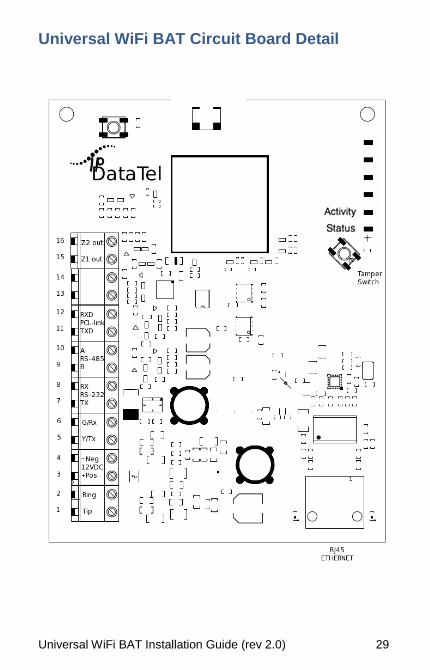
Universal WiFi BAT Circuit Board Detail
Universal WiFi BAT Installation Guide (rev 2.0) 30
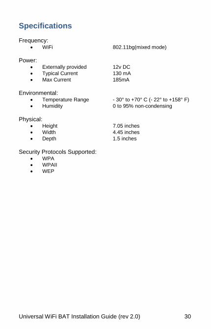
Specifications Frequency:
WiFi 802.11bg(mixed mode)
Power:
Externally provided 12v DC
Typical Current 130 mA
Max Current 185mA
Environmental:
Temperature Range - 30° to +70° C (- 22° to +158° F)
Humidity 0 to 95% non-condensing
Physical:
Height 7.05 inches
Width 4.45 inches
Depth 1.5 inches
Security Protocols Supported:
WPA
WPAII
WEP

www.ipdatatel.com
ipDatatel, LLC.13110 Southwest FreewaySugar Land, Texas 77478
Main: 713.452.2700Toll Free: 866.896.2944
* All product and company names are trademarks™ or registered® trademarks of their respective holders. Use of them does not imply any affiliation with or endorsement by them.