Embed Size (px)
Citation preview
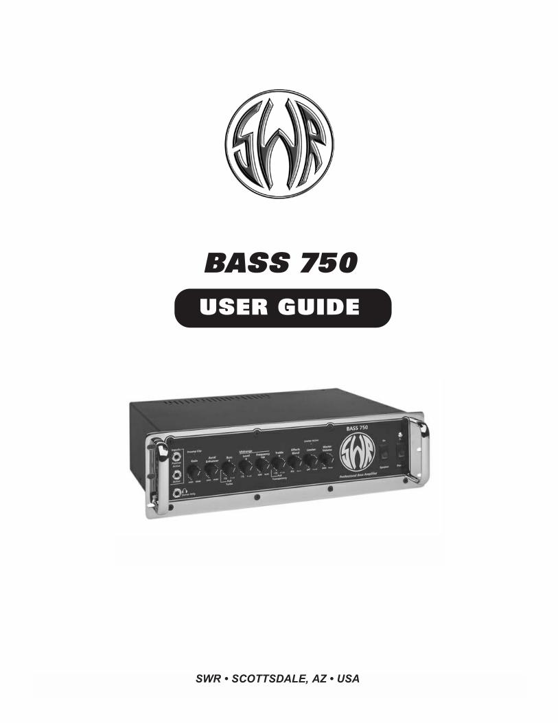
BASS 750
USER GUIDE
SWR • SCOTTSDALE, AZ • USA
IMPORTANT SAFETY INSTRUCTIONS
CAUTION: TO REDUCE RISK OF ELECTRIC SHOCK, DO NOT REMOVE THE COVER OR BACK. NO USER-SERVICEABLE PARTS INSIDE. PLEASE REFER TO A QUALIFIED SERVICE TECHNICIAN.
A. Read Instructions: All safety and operation instructions should be read before the product is operated.
B. Retain Instructions: The safety and operating instructions should be retained for future reference.
C. Heed Warnings: All of the warnings on this product and in the operating instructions should be adhered to.
D. Follow Instructions: All operating and use instructions should be followed.
E. Cleaning: Unplug this product from the wall outlet before cleaning. Do not use liquid cleaners or aerosol cleaners. Use aslightly damp cloth for cleaning.
F. Water and Moisture: Do not use this product near water; for example, near a swimming pool, wet basement, and the like.
G. Accessories: Do not place this product on an unstable cart, stand, tripod, bracket or table. The product may fall, causing serious injury to a child or adult, and serious damage to the product.
H. Ventilation: Slots and openings in the unit are provided for ventilation and to ensure reliable operation of the product, to pro-tect it from overheating, thus these openings must not be blocked or covered. This product should not be placed in a built-ininstallation such as a bookcase or rack unless proper ventilation is provided or the manufacturer's instructions have beenadhered to.
I. Grounding: This product is equipped with a three-wire grounding-type plug, a plug having a third (grounding) pin. This plug willonly fit into a grounding-type power outlet. This is a safety feature. If you are unable to insert the plug into the outlet, contactyour electrician to replace your obsolete outlet. Do not defeat the safety purpose of the grounding-type plug.
J. Power Cord Protection: Power supply cords should be routed so that they are not likely to be walked on or pinched by itemsplaced upon them, paying particular attention to cords at plugs and the point where they exit the product.
K. Lightning: For added protection of this product during a lightning storm or when it is left unattended and unused for long periods of time, unplug it from the wall outlet. This will prevent damage to the product due to lightning and power-line surges.
L. Overloading: Do not overload wall outlets or extension cords as this can result in a risk of fire or electric shock.
M. Object and Liquid Entry: Never push objects of any kind into this product through the openings as they may touch dangerousvoltage points or short out parts that could result in a fire or electric shock. Never spill liquid of any kind on the product.
N. Servicing: Do not attempt to service this product yourself as opening or removing covers may expose you to dangerous voltage or other hazards. Refer all servicing to qualified service personnel.
O. Damage Requiring Service: Unplug this product from the wall outlet and refer servicing to qualified service personnel underthe following conditions:
1) When the power supply cord has been damaged 2) If liquid has been spilled or objects have fallen into the product 3) If the product has been exposed to rain, water, or other conductive liquids 4) If the product does not operate normally by following the operating instructions 5) If the product has been dropped or damaged in any way6) When the product exhibits a distinct change in performance.
P. Replacement Parts: When replacement parts are required, be sure the service technician has used replacement parts speci-fied by the manufacturer or have the same characteristics as the original part. Unauthorized substitutions may result in fire, electric shock, or other hazards.
Q. Safety Check: Upon completion of any service or repairs to this product, ask the service technician to perform safety checksto determine that the product is in proper operating condition.
R. Heat: The product should be situated away from heat sources such as radiators, heat registers, stoves or other products thatproduce heat.
INTRODUCTION
CONGRATULATIONS......you are now the proud owner of a SWR Bass 750 amplifier! The Bass 750 was designed in response to ademand for an amplifier that delivered the volume and punch of classic high-powered amplifiers, coupled withthe sound and clarity that SWR is known for. At 750 watts (mono), the Bass 750 is extremely loud, and itssimple front panel controls make it a breeze to dial-in the perfect bass tone. After you spend some time withthe Bass 750 you’ll truly realize that “Feeling is Believing®.” Please read this entire manual carefully so thatyou can fully realize the potential of the Bass 750.
MADE IN THE U.S.A.SWR amplification is handmade and individually tested in the United States. Everyone at SWR sincerely hopesthat you are satisfied with your recent purchase, as we are extremely proud of the quality and attention thatgoes into each and every SWR product. We truly hope that your purchase of an SWR helps bring out the bestin your playing and adds to your enjoyment of music.
Thanks for choosing SWR!
The amplifier packaging should include the following items:
(1) Owner's Manual
(1) AC Power Cord
(1) Warranty/Product Registration Form
BASS 750 USER GUIDE
BASS 750 USER GUIDE • 1
SWR BASS 750
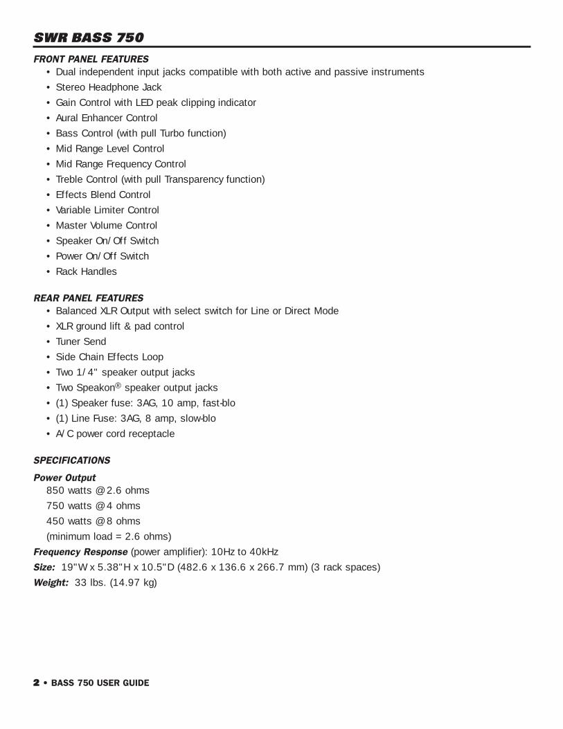
FRONT PANEL FEATURES• Dual independent input jacks compatible with both active and passive instruments
• Stereo Headphone Jack
• Gain Control with LED peak clipping indicator
• Aural Enhancer Control
• Bass Control (with pull Turbo function)
• Mid Range Level Control
• Mid Range Frequency Control
• Treble Control (with pull Transparency function)
• Effects Blend Control
• Variable Limiter Control
• Master Volume Control
• Speaker On/Off Switch
• Power On/Off Switch
• Rack Handles
REAR PANEL FEATURES• Balanced XLR Output with select switch for Line or Direct Mode
• XLR ground lift & pad control
• Tuner Send
• Side Chain Effects Loop
• Two 1/4" speaker output jacks
• Two Speakon® speaker output jacks
• (1) Speaker fuse: 3AG, 10 amp, fast-blo
• (1) Line Fuse: 3AG, 8 amp, slow-blo
• A/C power cord receptacle
SPECIFICATIONS
Power Output850 watts @ 2.6 ohms
750 watts @ 4 ohms
450 watts @ 8 ohms
(minimum load = 2.6 ohms)
Frequency Response (power amplifier): 10Hz to 40kHz
Size: 19"W x 5.38"H x 10.5"D (482.6 x 136.6 x 266.7 mm) (3 rack spaces)
Weight: 33 lbs. (14.97 kg)
2 • BASS 750 USER GUIDE
FRONT PANEL FEATURES
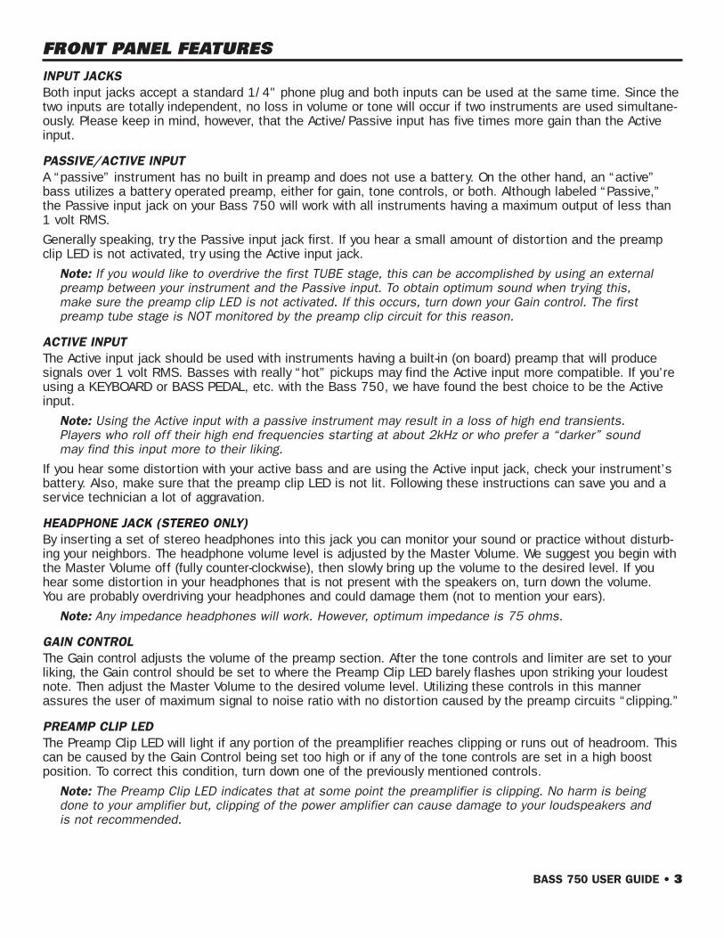
INPUT JACKSBoth input jacks accept a standard 1/4" phone plug and both inputs can be used at the same time. Since thetwo inputs are totally independent, no loss in volume or tone will occur if two instruments are used simultane-ously. Please keep in mind, however, that the Active/Passive input has five times more gain than the Activeinput.
PASSIVE/ACTIVE INPUTA “passive” instrument has no built in preamp and does not use a battery. On the other hand, an “active”bass utilizes a battery operated preamp, either for gain, tone controls, or both. Although labeled “Passive,”the Passive input jack on your Bass 750 will work with all instruments having a maximum output of less than1 volt RMS.
Generally speaking, try the Passive input jack first. If you hear a small amount of distortion and the preampclip LED is not activated, try using the Active input jack.
Note: If you would like to overdrive the first TUBE stage, this can be accomplished by using an externalpreamp between your instrument and the Passive input. To obtain optimum sound when trying this,make sure the preamp clip LED is not activated. If this occurs, turn down your Gain control. The first preamp tube stage is NOT monitored by the preamp clip circuit for this reason.
ACTIVE INPUTThe Active input jack should be used with instruments having a built-in (on board) preamp that will produce signals over 1 volt RMS. Basses with really “hot” pickups may find the Active input more compatible. If you’reusing a KEYBOARD or BASS PEDAL, etc. with the Bass 750, we have found the best choice to be the Activeinput.
Note: Using the Active input with a passive instrument may result in a loss of high end transients.Players who roll off their high end frequencies starting at about 2kHz or who prefer a “darker” soundmay find this input more to their liking.
If you hear some distortion with your active bass and are using the Active input jack, check your instrument’sbattery. Also, make sure that the preamp clip LED is not lit. Following these instructions can save you and aservice technician a lot of aggravation.
HEADPHONE JACK (STEREO ONLY)By inserting a set of stereo headphones into this jack you can monitor your sound or practice without disturb-ing your neighbors. The headphone volume level is adjusted by the Master Volume. We suggest you begin withthe Master Volume off (fully counter-clockwise), then slowly bring up the volume to the desired level. If youhear some distortion in your headphones that is not present with the speakers on, turn down the volume. You are probably overdriving your headphones and could damage them (not to mention your ears).
Note: Any impedance headphones will work. However, optimum impedance is 75 ohms.
GAIN CONTROLThe Gain control adjusts the volume of the preamp section. After the tone controls and limiter are set to yourliking, the Gain control should be set to where the Preamp Clip LED barely flashes upon striking your loudestnote. Then adjust the Master Volume to the desired volume level. Utilizing these controls in this mannerassures the user of maximum signal to noise ratio with no distortion caused by the preamp circuits “clipping.”
PREAMP CLIP LEDThe Preamp Clip LED will light if any portion of the preamplifier reaches clipping or runs out of headroom. Thiscan be caused by the Gain Control being set too high or if any of the tone controls are set in a high boostposition. To correct this condition, turn down one of the previously mentioned controls.
Note: The Preamp Clip LED indicates that at some point the preamplifier is clipping. No harm is beingdone to your amplifier but, clipping of the power amplifier can cause damage to your loudspeakers and is not recommended.
BASS 750 USER GUIDE • 3
AURAL ENHANCERSWR’s Aural Enhancer control was developed to bring out the fundamental low notes of the bass guitar,reduce certain frequencies that help mask the fundamentals, and enhance the high end transients. The result-ing frequency response is similar to that used for recording the bass in the studio. This effect becomes moreradical as the control is turned to maximum. The result is a more “transparent” sound and is especially notice-able when slapping/thumb-style on the bass guitar.
Basically, the Aural Enhancer can be described as a tone shaping control, as it is a passive R/C network thatalters the frequency response throughout the bass spectrum. This pre-shaping is “blended” into the originalsignal via the Aural Enhancer control. Exact frequencies affected are dependent on the characteristics of theinstrument used.
ACTIVE TONE CONTROL SECTION
BASS CONTROLThe Bass control adjusts the level of the lower or bass frequencies. Starting at mid-center click-position, turn-ing the control counter-clockwise cuts the bass response; turning the control clockwise boosts the bassresponse.
PULL TURBO FUNCTIONPulling the bass control to the out position widens the bandwidth of the bass control to include frequenciesdown to 30Hz (low B on a five string bass). Since some of these notes can be felt more than heard, it is espe-cially important to keep an eye on the preamp clip LED. Constant clipping of these frequencies can diminishthe life of the speakers or cause them to fail.
MID RANGE SECTION
Level ControlThe Level control cuts or boosts the frequency set by the Frequency control. Starting at mid-position, turningthe Level control counter clockwise cuts the desired tone. Turning the Level control clockwise boosts thedesired tone. When the level control set at mid (center click) position, turning the frequency control will haveno affect on the sound.
To find the midrange area you’re looking for:
1. Adjust the Level control to the full boost or cut position.
2. Rotate the Frequency control until the desired area you wish to cut or boost is found.
3. Adjust the Level control to the desired amount of cut or boost
Frequency ControlThe Frequency control sets the area that is to be cut or boosted by the Level Control. If the Level control is setat mid-position, turning the Frequency knob will have NO affect.
Note: If you need to “cut through” the band a little more, try boosting 200 to 400Hz. If you like a moretransparent sound, try cutting at 800Hz. The midrange area is especially useful in controlling fretlessbasses and their inherent qualities.
TREBLE CONTROLThe Treble control is a shelving type tone control that cuts or boosts the high notes and their octaves. Startingfrom mid position, turning the control counter-clockwise cuts the highs while turning the control clockwiseboosts the treble region.
PULL TRANSPARENCY FUNCTIONIn the normal (in) position, the shelving point of the treble control is approximately 2kHz. By pulling the knoboutward, the shelving point is changed to 4kHz.
4 • BASS 750 USER GUIDE
EFFECTS BLENDThis control blends the signal sent from your bass with that coming from your effects unit. With the EffectsBlend control fully counter-clockwise, no signal from your effects will be heard (“dry”). As you turn this controlclockwise, more of the effect can be heard in the overall sound. When the Blend control is fully clockwise(“wet”), no true or unaffected signal is heard other than what your effects unit provides. If your effects unithas a similar control, adjust it to the fully “wet” position. This will avoid any possible phasing problems.
The Blend circuit is similar to that used on recording consoles with the effects loop on a “side chain” to thenormal circuit. Unless the control is set to the full “wet” position, you will always get the full sound of yourinstrument AND get the diversity an effects unit offers. This circuit is also effective in reducing noise generat-ed by effects units because it is located after the gain stages in the preamp.
The Effects Blend functions only when the effects loop is being used. It is activated when a 1/4" phone plugis inserted into the Effects Receive jack. See the “Effects Loop” section for more information.
LIMITER CONTROLThis Limiter circuit is located after (post) the Master Volume and before (pre) the power amplifier. Therefore, theLimiter is driven by the Master Volume. Its threshold (or starting point) is set by the Limiter control and can beused to achieve maximum overall apparent volume without unduly overdriving the power amplifier or internalspeakers. Turning the Limiter control clockwise (toward “max”) increases the effect of the Limiter circuit.
LIMITER ACTIVE LEDWhen the threshold of the Limiter circuit is reached, the green Limiter Active LED will light. This LED will beinactive when the Limiter is set to the “off” position or when playing at lower levels.
MASTER VOLUMEThe Master Volume adjusts the level being sent to the power amplifier section of the Bass 750 and controlsthe overall volume of the unit. It DOES NOT affect the level of the record XLR output in the “line” position.
Losses caused by effects units can be recovered by increasing the Master Volume.
SPEAKER ON/OFF SWITCHMoving the Speaker On/Off Switch to the “On” position allows the signal from the amplifier to be heardthrough any speaker enclosure(s) connected to the Bass 750’s output section. Moving the Speaker On/OffSwitch to the “OFF” position disables the Bass 750’s output section. This feature allows the user to:
1. Use the XLR Output without using the internal speakers. This is especially useful in recording when you are not miking the speakers and only a direct signal is required.
2. Tune up without interfering with other band members while using the Tuner Send feature.
Note: If you do not hear any sound when you plug in and your system is properly connected, check theposition of this switch!
POWER ON/OFF SWITCHMoving the Power Switch to the “On” position will turn on the amplifier as indicated by the Power LED lighting(directly above the switch).
REAR PANEL FEATURES
AC OR MAINS FUSEThis fuse is provided to protect the internal electronics against power surges, etc. It also protects the unitagainst itself should one of the internal components fail. If this fuse should open, replace it with the sametype of fuse and rating.
Note: Do note defeat the purpose of this feature by using a fuse of a higher value. It could damage theunit and will void your warranty!
BASS 750 USER GUIDE • 5
Proper size of the AC fuse for all countries is 3AG. Proper rating of the fuse is as follows:
Japan: 8 amp slo-blo
United States: 8 amp slo-blo
Europe (240V): 4 amp slo-blo
AC CORD RECEPTACLEAccepts a standard AC power cable (supplied with the Bass 750), used with almost all current musical, profes-sional and household electronic devices. If you misplace your AC power cable, a replacement can be found atalmost any computer. electronics, or pro audio store.
Note: The rating for this cable is 3 conductor, 10 amperes MINIMUM. If replacement is necessary, or ifyou wish to buy a longer cable, look for the rating on the cable and be sure it is at least 10 amps. Makesure the AC cord is plugged in all the way in both the amp and the wall socket. If your cord everbecomes frayed or split, replace it immediately.
EFFECTS LOOPThe Effects Loop should accept any effect such as a chorus, flanger, etc. It is designed as a “side chain”function and works exactly like that of studio consoles. Some effects units have an input level adjustmentswitch. Whenever possible, set it at 0 dB. If that’s not an option, +4 dB is fine. The level going to your effectis controlled by the Gain control on the front panel of the Bass 750.
Use of the Effects Loop should greatly reduce the noise generated by effects units (as compared to using theeffect between your instrument and the input jack). This is because the loop is after the preamp gain stages.
Note: The effects loop must be used in conjunction with the Effects Blend control on the front panel.When that control is in the “dry” position, no effects will be heard.
All patch cords used with the Effects Loop should be as short as possible and should be routed as directly aspossible. Running patch cables over the top of the Bass 750 (as with any amplifier) can induce hum in thecables.
SEND JACKRun a shielded patch cable from the Bass 750’s “Send” jack to the INPUT of your effects unit. Output imped-ance of the send jack is 100 ohms. This jack can be used as a line level output to connect a slave poweramp, such as SWR’s Power 750. It may also be used as an unbalanced record out.
RECEIVE JACKRun a shielded patch cord from the Bass 750’s “Receive” jack to the OUTPUT jack of your effects unit. Aunique feature of the receive jack is that you can practice along with pre-recorded music. To accomplish this,insert a tape recorder or other sound source into the “Receive” jack (make sure it is a MONO source). Usingthe Effects Blend control, adjust the level of recorded music from the Receive to the “live” sound of yourinstrument. The mixed sound will be heard through your speakers. This is an excellent way to practice alongwith drum machines. Input impedance of the Receive jack is 27kohms minimum.
Note: Inserting a plug into the “Receive” jack activates the Effects Blend control. The control receives thiscommand through the ground created by the phone plug making contact with the jack. The plug must be amono plug (tip and ground). If you have a stereo plug only, tie the ring and the ground together.
PREAMP OUT JACKThe Preamp Out jack is a post-EQ output that allows a signal to be run to an external power amp (such as thePower 750) or recording device.
SPEAKER FUSEThe speaker fuse is provided to protect your speakers in the unlikely event of a power amp failure or to protectyour power amplifier from incorrect speaker impedances or connections. Size and rating of the fuse is 10 amp,fast blow. Do not defeat the purpose of this feature by using a higher rated fuse as it could void your warrantyand further damage your amp.
6 • BASS 750 USER GUIDE
The fuse can open as a result of a fault in the speaker cable, the speakers themselves, or the power amp beingsent well into clipping. With this in mind, we recommend keeping spare fuses with the amplifier at all times.
SPEAKER JACKSTwo 1/4" phone jacks (wired in parallel) and two Speakon® connectors (wired in parallel) are provided forhooking up your speaker system. The minimum load (or impedance) the Bass 750 is designed to drive is 2.67ohms (the equivalent of one 8 ohm cab and one 4 ohm cab connected in parallel).
It should be noted that the Bass 750’s preamp section can be run without speakers attached to the speakerjacks. (See “Speaker Off/On Switch” under “Front Panel Features.”) This is helpful when using the amplifierfor recording purposes (via the XLR output) and speakers are not required.
Note: The frequency response of the Bass 750 is far greater than usually found in musical instrumentamplifiers (10Hz to 40kHz). This was engineered in order to give the bass player the same punch andclarity on stage as found in the studio or concert P.A. systems. Therefore, it is doubly important that yoube aware of the impedance and power rating of the speakers that you intend to use and that they arecompatible with the Bass 750. Speakers that have been overdriven are easy to detect and are not cov-ered under warranty.
SPEAKER CABLESpeaker cable should be made of 18-gauge, or heavier, wire. (The thicker the wire, the lower the gauge, so 18-gauge is heavier than 20-gauge and so on.) Do not use instrument cables to hook up your speakers. This canresult in intermittent power loss, cause your power amp to oscillate and damage itself and/or your speakers,and render the cables useless for any purpose.
To connect the Bass 750 to your speakers via the Speakon output jacks, a Neutrik Speakon cable is required.These cables are NOT supplied with the Bass 750, but are available from your local music retailer or directlyfrom the SWR Service Department.
XLR PADThe XLR Pad control adjusts the level of the Balanced XLR Output. Rotating the control clockwise raises thelevel at this output.
GROUND LIFTThe XLR Pad has a built-in Ground Lift for the Balanced out. Pulling the knob outward lifts the ground (pin 1). If a persistent hum exists after trying both positions of the ground lift, there is probably a mis-wire or badground in the feed lines to the board or console or a dirty or miswired A/C socket. SWR recommends the pur-chase of an AC wall socket tester which can identify proper wiring (available at most hardware stores). These inexpensive devices are a simple way to protect you and your equipment from faulty electrical systems.
LINE/DIRECT SWITCHThe Line/Direct switch gives the user the option of either a line signal (preamp out) or direct signal from theinstrument. The signal appearing at the XLR out is slightly “hotter” than normal D.I.’s. You may want to informthe engineer of this.
To use the Line/Direct function, position the knob in the desired location. Make sure the switch is all the wayto the left or right to avoid intermittants.
Note: Turn-off transients appear at the record outs when the amplifier is shut down. It is recommendedthat equipment being used in conjunction with the record out be turned down, off, or disconnectedBEFORE the Bass 750 is turned off.
BALANCED XLR OUTThe Balanced XLR out is a true electronically balanced record out. The signal appearing at the XLR out is gov-erned by the position of the XLR Pad. In the LINE position, all front panel controls are functional except theMaster Volume, and the signal is essentially the same as that heard through your speaker system. The outputlevel in the Line position is adjusted by the GAIN control on the front panel. If you are using an effect, this willalso appear mixed in the signal when you are in the line mode.
In the “Direct” position, the Balanced XLR out becomes an active TUBE direct box. No front panel controls arefunctional and the level is only adjustable via your instrument.
BASS 750 USER GUIDE • 7
Wiring for the XLR connector is as follows:
Pin 1 = ground, Pin 2 = +, Pin 3 = – (negative) (American Standard)
The Bass 750 is compatible with Phantom Power-equipped mixing consoles.
TUNER SENDThe Tuner Send allows the user to plug an instrument tuner into this jack and tune up without having to unplugand go back and forth from amp to tuner. This feature is totally isolated from the rest of the preamp and willfunction regardless of the settings on the front panel. Being on a side chain (isolated) also avoids loadingdown of the instrument causing a loss in dynamic range.
To use this feature, plug in a shielded patch cord from the Tuner Send output to the input jack on your tuner.Turn the amplifier on and you’re ready to go. If you do not wish to monitor your sound during the tuningprocess, switch the Speaker On/Off switch to the “off” position.
INTERNAL FEATURES
VACUUM TUBE (VALVE)SWR installs a specially selected 12AX7 dual triode tube (valve) in the preamp section of every Bass 750. Ifthis tube needs replacing, we recommend that you replace it with a similar high quality product. This tube willrequire replacement only in the event it becomes noisy or microphonic (sounds like glass tinkling in the back-ground of certain notes), or completely fails causing no signal.
POWER ON TRANSIENTWhen the Bass 750’s power switch is moved to the “On” position, you will hear a turn-on transient (soundslike a “thud”) through your speakers. This will not harm speakers made by SWR, however, you may wait to connect your speaker cable to the Bass 750 until after powering up. Just make sure you are not playingthrough the unit when you make the connection, as it could cause a speaker fuse to blow. Eliminating thistransient would require a component called a relay. Since relays tend to degrade signal quality and often fail,we decided not to incorporate this type of component in the Bass 750.
A FEW WORDS CONCERNING HEATPlease be aware that the chassis of your amplifier can get quite warm during normal use. This is especiallytrue if you are using a 2.67 ohm total impedance, as this introduces the least efficient condition possible forthe unit (i.e., power drawn from the outlet in relation to power produced in the speakers). The difference inthese two figures can be quite high, basically resulting in the equivalent of putting a high wattage light bulbinside a metal box—which would obviously get quite warm.
Furthermore, most musical instrument amplifiers on the market today utilize steel for their chassis, which inmost cases is considerably cheaper than aluminum and does not conduct heat as well. With the exception ofthe front panel (which is made of steel), the Bass 750 utilizes an all aluminum chassis, which has less impuri-ties than steel, is less susceptible to rust, and is a better conductor of heat. This results in the chassis actingas a heatsink—drawing heat away from internal heat-producing components, thus extending their life and mak-ing the Bass 750 a more reliable amplifier.
You should be aware of a heat-related condition known as “over biasing.” If one or more of the power amplifiersin your Bass 750 becomes over biased, it may cause the unit to generate more heat than normal. This condi-tion can be recognized by turning on your amplifier and letting it sit without speakers plugged in and withoutplaying it. If under these conditions your unit becomes quite warm, it may be over biased. This situation shouldbe attended to and can be easily remedied in about 15 minutes by a qualified technician. An amplifier canbecome over biased through continuous vibration or by any large jolt received in shipping, transportation, etc.
RACK MOUNTING INSTRUCTIONSTo preserve the beauty and reliability of your amplifier, we recommend that you install your amplifier in a rackcase. The Bass 750 is completely ready to be rack mounted and needs no additional parts or accessoriesother than the case itself. The Bass 750 takes up three full rack spaces (it is 5-3/8" high). If the rack thatyou mount the Bass 750 in requires that the rubber feet on the bottom of the chassis be removed, pleaseremember to REPLACE the screws, as they help to reinforce the chassis.
8 • BASS 750 USER GUIDE

The Bass 750 should be mounted as close to the bottom of the rack case as possible. The height of the rub-ber feet was chosen so that when you slide the unit in the bottom of the rack case, the rack mounting holeson the front panel will line up with the mounting holes of the rack rail. This prevents the Bass 750 from flexingdownward if the rack case is dropped. If you must mount the Bass 750 in an area of the rack other than thebottom space, a piece of wood or similar solid material should be installed between the bottom of the rackcase and the bottom of the amplifier to prevent flexing of the amplifier’s chassis. Severe or constant flexing ofthe chassis can damage the amplifier and is not covered under the warranty.
Don’t neglect your amp after it has been installed in a rack case. Continuous transportation and vibration cancause screws to become loose, both on the Bass 750 and on your rack case rails. We recommend that atleast once a month you remove the Bass 750 from the case and tighten all outside screws (especially on thefront panel). Then check all the connections in your rack case and reinstall the unit.
BASS 750 USER GUIDE • 9
LIMITED WARRANTY
The BASS 750 from FMIC is warranted to the original consumer purchaser for TWO YEARS from the date of purchase, against defects in materials and workmanship and provided that it is purchased froman Authorized SWR Dealer. This warranty applies only to products purchased in the USA or Canada.
This warranty is VOID if the unit has been damaged due to accident, improper handling, installation oroperation, shipping damage, abuse or misuse, unauthorized repair or attempted repair, or if the serialnumber has been defaced or removed. FMIC reserves the right to make such determination on thebasis of inspection by an Authorized FMIC Service Center.
All liability for any incidental or consequential damages for breach of any expressed or implied warranties is disclaimed and excluded herefrom.
Some states do not allow limitations on how long an implied warranty lasts, or the exclusion or limitation of incidental or consequential damages, so that the above exclusion may not apply to you.This warranty gives you specific legal rights and you may also have other rights which vary from stateto state.
SHOULD YOUR AMPLIFIER REQUIRE REPAIR:
Locate your original sales receipt showing details of purchase including date of purchase, model,and serial number.
Find the nearest Authorized FMIC Service Center by calling FMIC Consumer Relations at: (480) 596-7195, or on the web, at: http://www.mrgearhead.com/faq/allservice.html
To receive warranty service, return the complete product to an Authorized FMIC Electronics Service Center, with proofof purchase, during the applicable warranty period. Transportation costs are not included in this Limited Warranty.
Defective products that qualify for coverage under this warranty will be repaired or replaced, at FMIC'sdiscretion, with a like or comparable product, without charge.
➊
➋
➌
➍
For a complete list of Authorized FMIC Service Centers — and to learn more about SWR products and artists —
point your browser at:
swrsound.com
SWR8860 E. Chaparral Rd. Suite 100 • Scottsdale, AZ 85250-2618 USA
Phone: (480) 596-9690 • Fax: (480) 367-5262Ô, E-mail:Ô [email protected]
Part # 320026REV. 08/2001 © 2001 SWR