Embed Size (px)
Citation preview

Basis of Structural Design
Course 13
EN 1990:
The partial factor method (cont.)
Course notes are available for download athttps://www.ct.upt.ro/studenti/cursuri/stratan/bsd.htm
Ultimate limit states
The following ultimate limit states shall be verified as relevant:– EQU: Loss of static equilibrium;
– STR: Internal failure or excessive deformation;
– GEO: Failure or excessive deformation of the ground where the strengths of soil or rock are significant in providing resistance;
– FAT: Fatigue failure of the structure or structural members.

Ultimate limit states
EQU: Loss of static equilibrium of the structure or any part of it considered as a rigid body, where:– minor variations in the value or the spatial distribution of actions
from a single source are significant, and
– the strengths of construction materials or ground are generally not governing;
Example: a bridge deck launched with a counterweight where loss of static equilibrium may be possible

Ultimate limit states
STR: Internal failure or excessive deformation of the structure or structural members, including footings, piles, basement walls, etc., where the strength of construction materials of the structure governs;
Example: failure of a beam supporting a floor due to excessive stresses
Mmax

Ultimate limit states
GEO: Failure or excessive deformation of the ground where the strengths of soil or rock are significant in providing resistance;Example: resistance of foundations like footings, piles, etc.

Ultimate limit states
FAT: Fatigue failure of the structure or structural members.Examples: Cracks developing in steel bridges due to repetitive loading generated by traffic

Verifications of static equilibrium and resistance
When considering a limit state of rupture or excessive deformation of a section, member or connection (STR and/or GEO), it shall be verified thatEd Rd
where:Ed is the design value of the effect of actions such as internal force, moment or a vector representing several internal forces or moments;Rd is the design value of the corresponding resistance.

ULS: Combination of actions
For each critical load case, the design values of the effects of actions (Ed) shall be determined by combining the values of actions that are considered to occur simultaneously
Each combination of actions should include:– a leading variable action, or
– an accidental action.
Where the results of a verification are very sensitive to variations of the magnitude of a permanent action from place to place in the structure, the unfavourable and the favourable parts of this action shall be considered as individual actions
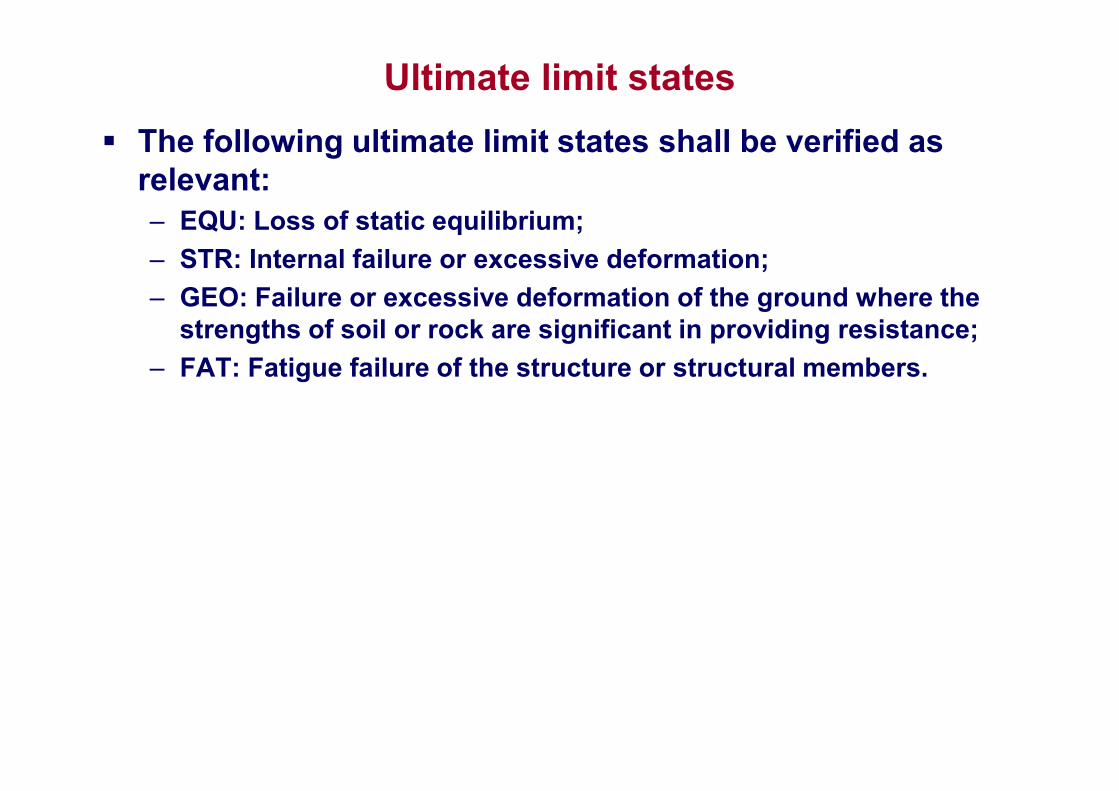
ULS: Combination of actions
Combinations of actions for persistent or transient design situations (fundamental combinations)
The general format of effects of actions
and can be simplified as:
The combination of action in curly braces {} can be expressed as:
where "+" implies "to be combined with" implies "the combined effect of"

ULS: Combination of actions
Gk,j - characteristic permanent action j
G,j - partial safety factor for permanent load Gk,j
P - prestressing
P - partial safety factor for prestressing action P
Qk,1 - leading variable action
Q,1 - partial safety factor for variable load Qk,1
Qk,i - variable action i
Q,i - partial safety factor for variable load Qk,i
0,i - takes into account the reduced probability of the simultaneous occurrence of two (or more) independent variable actions

ULS: Combination of actions
Combinations of actions for accidental design situations
Ad - design value of the accidental action
Combinations of actions for seismic design situation
AEd - design value of the seismic action– permanent actions are taken with characteristic values
– seismic action is taken with design value
– variable loads are taken with the quasi-permanent value 2Qk

ULS: Combination of actions
Partial factors for actions and combinations of actions: and factors are obtained from EN 1990 or CR0-2012:– permanent actions: G,sup = 1.35
– permanent actions: G,inf = 0.9
– variable actions: Q = 1.5
– 0,i = 0.7, with the exception of loads in storage facilities, water pressure, etc, when 0,i = 1.0
Example of fundamental load combinations
The partial factors for properties of materials and products should be obtained from EN 1992 to EN 1999

Serviceability limit states
At the SLS it shall be verified that:Ed Cd
where:– Cd is the limiting design value of the relevant serviceability
criterion.
– Ed is the design value of the effects of actions specified in the serviceability criterion, determined on the basis of the relevant combination
Serviceability limit states in buildings should take into account criteria related, for example, to floor stiffness, differential floor levels, storey sway or/and building sway and roof stiffness.
Stiffness criteria may be expressed in terms of limits for vertical deflections and for vibrations.
Sway criteria may be expressed in terms of limits for horizontal displacements.

Serviceability limit states
EN 1990: "The serviceability criteria should be specified for each project and agreed with the client".
Schematic representation of vertical deflections:– wc - Precamber in the unloaded structural member
– w1 - Initial part of the deflection under permanent loads of the relevant combination of actions
– w2 - Long-term part of the deflection under permanent loads
– w3 - Additional part of the deflection due to the variable actions of the relevant combination of actions
– wtot - Total deflection as sum of w1, w2, w3
– wmax - Remaining total deflection taking into account the precamber

Serviceability limit states
Horizontal displacements can be represented schematically:– u - Overall horizontal displacement
over the building height H
– ui - Horizontal displacement over a storey height Hi

SLS: Combination of actions
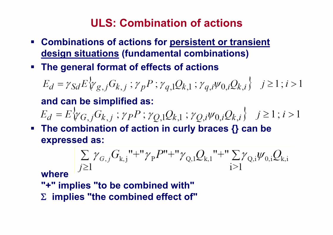
Three categories of combinations of actions are proposed in EN: – characteristic (normally used for irreversible limit states, e.g. for
exceeding of some cracking limits in concrete)
– frequent (is normally used for reversible limit states) and
– quasi-permanent (is normally used for assessment of long-term effects)
The appropriate combinations of actions should be selected depending on serviceability requirements and performance criteria imposed for the particular project, the client or the relevant national authority
SLS: Combination of actions
Characteristic combination
Frequent combination
Quasi-permanent combination
For serviceability limit states the partial factors M for the properties of materials should be taken as 1.0 except if differently specified in EN 1992 to EN 1999.

Examples of limiting values for vertical deflections

Examples of limiting values for horizontal deflections
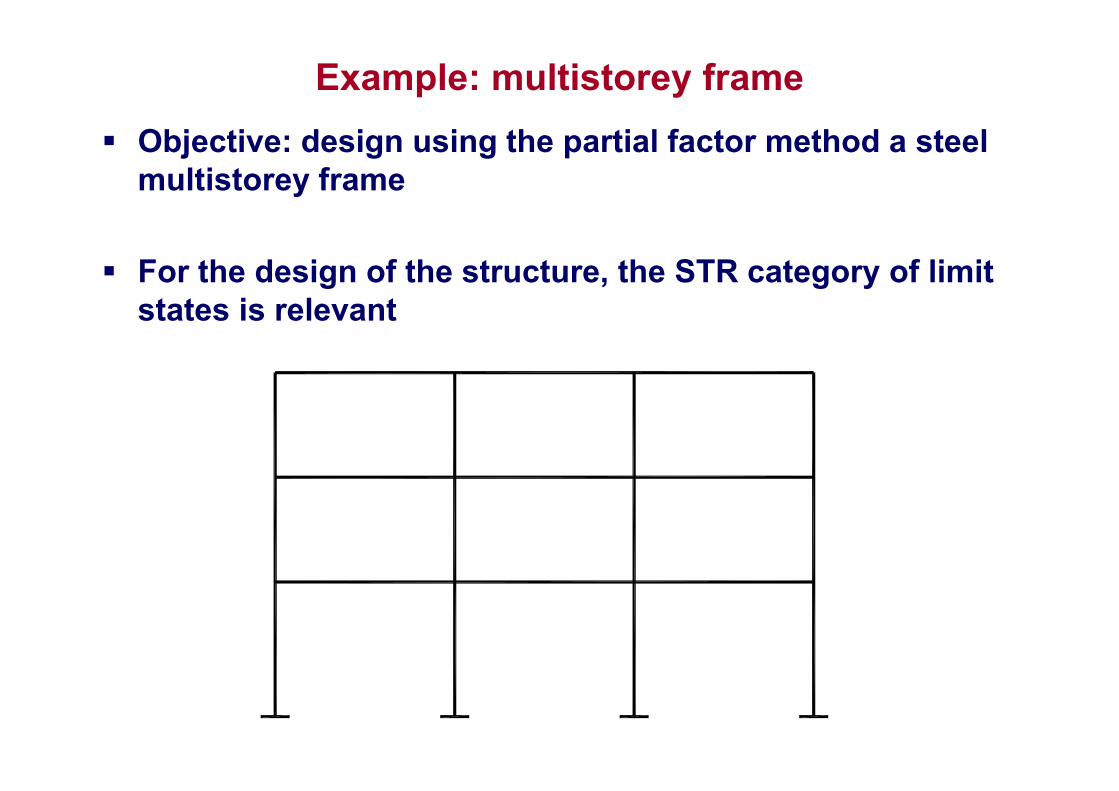
Example: multistorey frame
Objective: design using the partial factor method a steel multistorey frame
For the design of the structure, the STR category of limit states is relevant

Example: multistorey frame
The following actions can be identified:– Permanent loads Gk
– Imposed loads Qk
– Snow load Sk
– Wind load Wk
– Seismic action Aed
Self-weight (Gk,1) Dead load on floors (Gk,2) Exterior cladding (Gk,3)
Snow load (Sk) Wind load (Wk)
Imposed load (Qk,1)Imposed load -
chessboard (Qk,2)Seismic load (Aed)

Example: multistorey frame
Of the four possible design situations,– Persistent design situations,
– Transient design situations,
– Accidental design situations,
– Seismic design situations.
Two categories of limit states need to be considered:– Ultimate limit states (ULS)
– Serviceability limit states (SLS)
Seismic designsituation
ULS SLS
Persistent designsituation
ULS SLS
most relevant

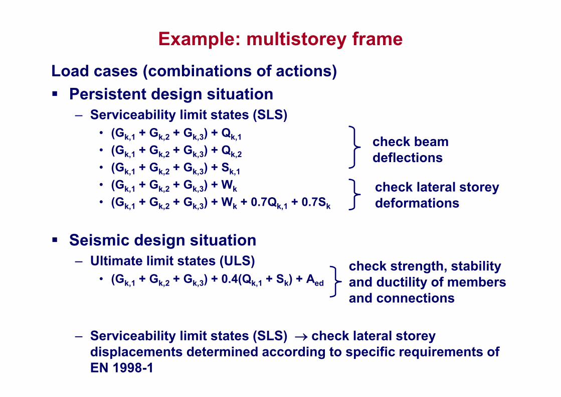
Example: multistorey frame
Load cases (combinations of actions)
Persistent design situation– Ultimate limit states (ULS)
– Serviceability limit states (SLS)
Seismic design situation– Ultimate limit states (ULS)
– Serviceability limit states (SLS) see EN 1998-1

Example: multistorey frame
Load cases (combinations of actions)
Persistent design situation– Ultimate limit states (ULS)
• 1.35(Gk,1 + Gk,2 + Gk,3) + 1.5Qk,1
• 1.35(Gk,1 + Gk,2 + Gk,3) + 1.5Qk,2
• 1.35(Gk,1 + Gk,2 + Gk,3) + 1.5Sk,1
• 1.35(Gk,1 + Gk,2 + Gk,3) + 1.5Wk
• 0.9(Gk,1 + Gk,2 + Gk,3) + 1.5Wk
• 1.35(Gk,1 + Gk,2 + Gk,3) + 1.5Qk,1 + 1.05Sk
• 1.35(Gk,1 + Gk,2 + Gk,3) + 1.5Sk + 1.05Qk,1
• 1.35(Gk,1 + Gk,2 + Gk,3) + 1.5Qk,1 + 1.05Sk + 1.05Wk
• 1.35(Gk,1 + Gk,2 + Gk,3) + 1.5Sk + 1.05Qk,1 + 1.05Wk
• 1.35(Gk,1 + Gk,2 + Gk,3) + 1.5Wk + 1.05Qk,1 + 1.05Sk
check strength and stability of members and connections
Example: multistorey frame
Load cases (combinations of actions)
Persistent design situation– Serviceability limit states (SLS)
• (Gk,1 + Gk,2 + Gk,3) + Qk,1
• (Gk,1 + Gk,2 + Gk,3) + Qk,2
• (Gk,1 + Gk,2 + Gk,3) + Sk,1
• (Gk,1 + Gk,2 + Gk,3) + Wk
• (Gk,1 + Gk,2 + Gk,3) + Wk + 0.7Qk,1 + 0.7Sk
Seismic design situation– Ultimate limit states (ULS)
• (Gk,1 + Gk,2 + Gk,3) + 0.4(Qk,1 + Sk) + Aed
– Serviceability limit states (SLS) check lateral storey displacements determined according to specific requirements of EN 1998-1
check beam deflections
check lateral storey deformations
check strength, stability and ductility of members and connections


![gk;j lsds.Mjh Ldwy ijh{kk - Board of Secondary …mpbse.nic.in/12TH/PHYSICS/PHYSICS-2.pdf1 gk;j lsds.Mjh Ldwy ijh{kk (Higher Secondary School Examination) [ PHYSICS ] (Hindi and English](https://img.pdfslide.us/doc/110x75/5ada1c767f8b9add658c342f/gkj-lsdsmjh-ldwy-ijhkk-board-of-secondary-mpbsenicin12thphysicsphysics-2pdf1.jpg)