Embed Size (px)
Citation preview

Basis for Thevenin and Norton Equivalent Circuits
Objective of Lecture Describe the differences between ideal and real voltage
and current sources
Demonstrate how a real voltage source and real current source are equivalent so one source can be replaced by the other in a circuit.
Chapter 4.4 Fundamentals of Electric Circuits
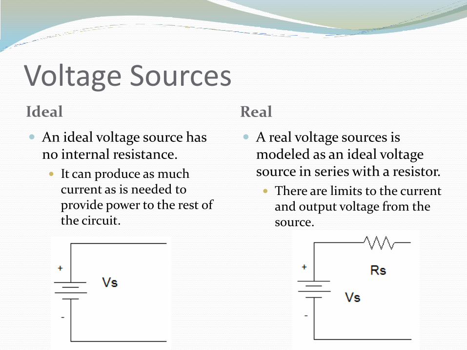
Voltage SourcesIdeal Real
An ideal voltage source has no internal resistance.
It can produce as much current as is needed to provide power to the rest of the circuit.
A real voltage sources is modeled as an ideal voltage source in series with a resistor.
There are limits to the current and output voltage from the source.
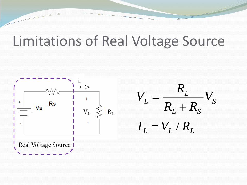
Limitations of Real Voltage Source
Real Voltage Source
LLL
S
SL
LL
RVI
VRR
RV
/
VL
IL
RL
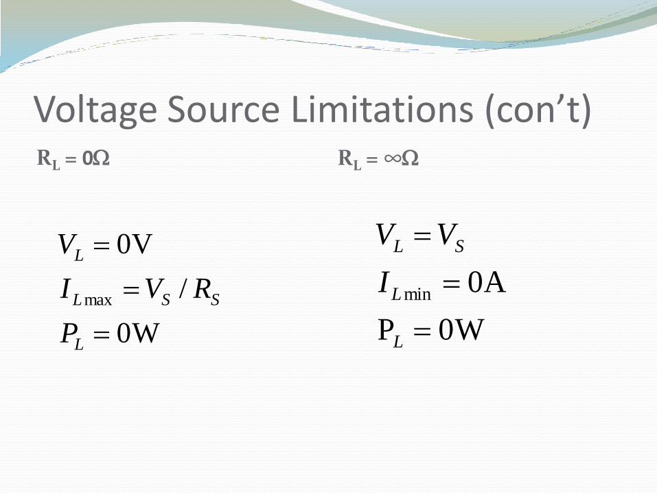
Voltage Source Limitations (con’t)RL = 0W RL = ∞W
W0
/
V0
max
L
SSL
L
P
RVI
V
W0P
A 0min
L
L
SL
I
VV
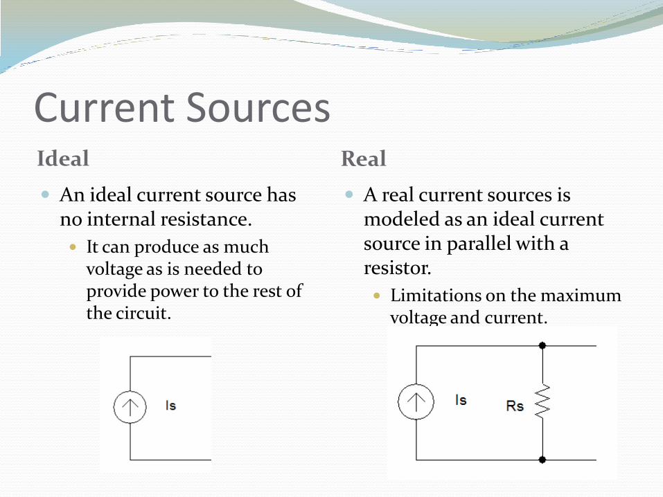
Current SourcesIdeal Real
An ideal current source has no internal resistance.
It can produce as much voltage as is needed to provide power to the rest of the circuit.
A real current sources is modeled as an ideal current source in parallel with a resistor.
Limitations on the maximum voltage and current.
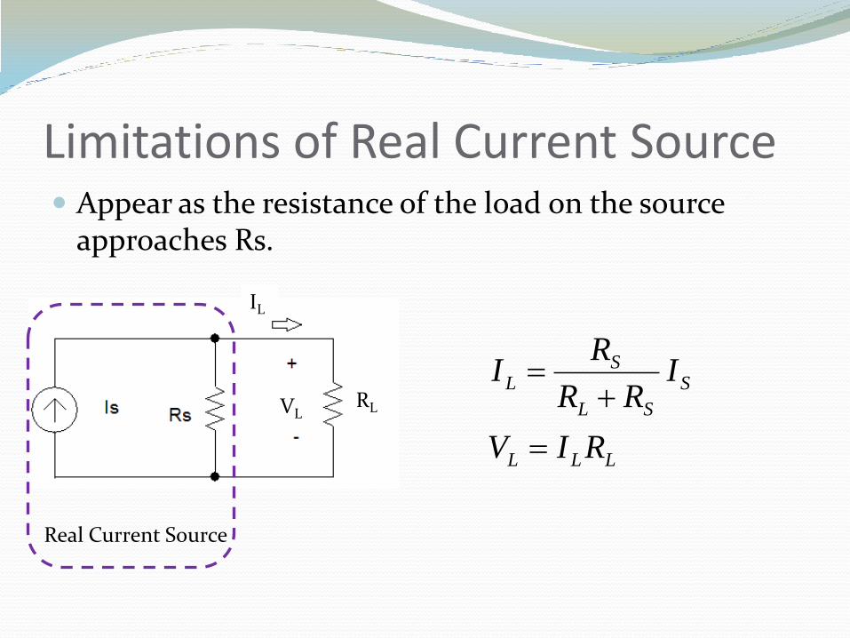
Limitations of Real Current Source Appear as the resistance of the load on the source
approaches Rs.
Real Current Source
LLL
S
SL
SL
RIV
IRR
RI
VL
IL
RL
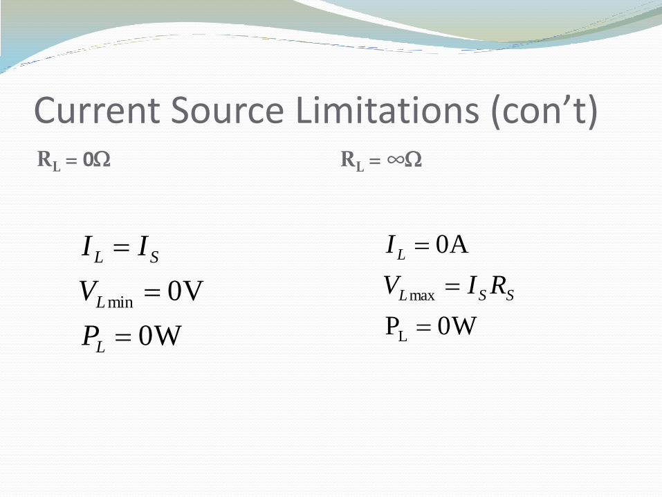
Current Source Limitations (con’t)RL = 0W RL = ∞W
W0
V0min
L
L
SL
P
V
II
W0P
A0
L
max
SSL
L
RIV
I
Electronic Response For a real voltage source, what is the voltage across the
load resistor when Rs = RL?
For a real current source, what is the current through the load resistor when Rs = RL?
Equivalence An equivalent circuit is one in which the i-v
characteristics are identical to that of the original circuit.
The magnitude and sign of the voltage and current at a particular measurement point are the same in the two circuits.
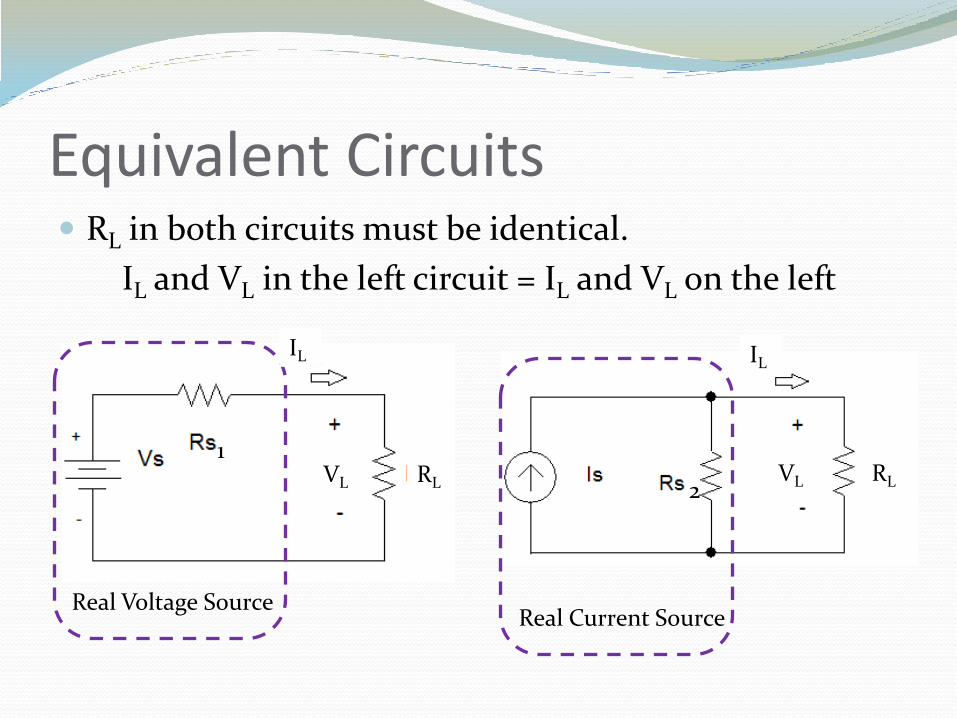
Equivalent Circuits RL in both circuits must be identical.
IL and VL in the left circuit = IL and VL on the left
Real Current SourceReal Voltage Source
1
2VL
IL
RL VL
IL
RL
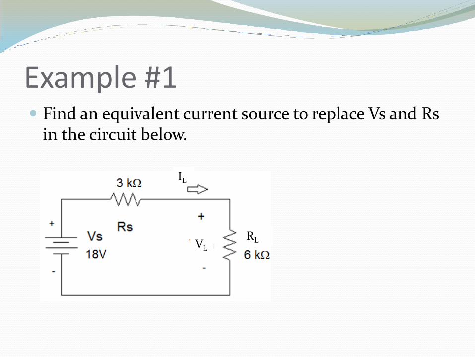
Example #1 Find an equivalent current source to replace Vs and Rs
in the circuit below.
VL
IL
RL
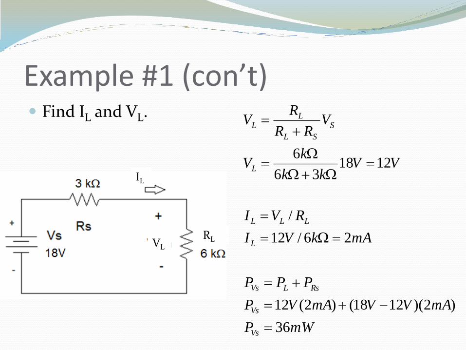
Example #1 (con’t) Find IL and VL.
mWP
mAVVmAVP
PPP
mAkVI
RVI
VVkk
kV
VRR
RV
Vs
Vs
RsLVs
L
LLL
L
S
SL
LL
36
)2)(1218()2(12
26/12
/
121836
6
W
WW
W
VL
IL
RL
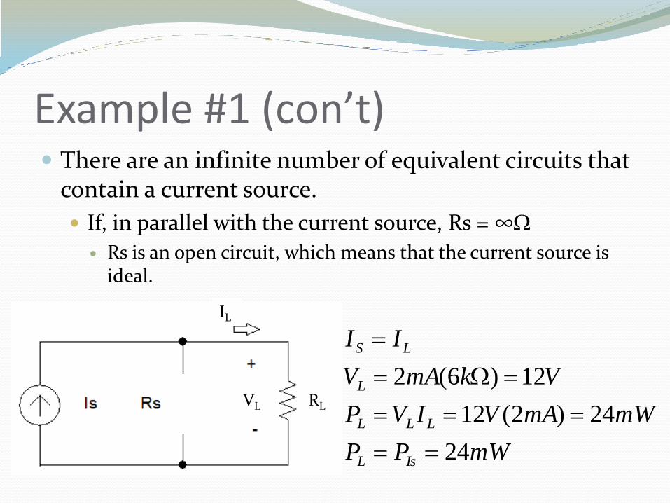
Example #1 (con’t) There are an infinite number of equivalent circuits that
contain a current source.
If, in parallel with the current source, Rs = ∞W
Rs is an open circuit, which means that the current source is ideal.
VL
IL
RL
mWPP
mWmAVIVP
VkmAV
II
IsL
LLL
L
LS
24
24)2(12
12)6(2
W
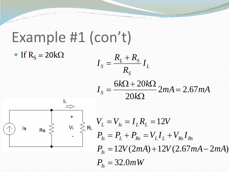
Example #1 (con’t) If RS = 20kW
mWP
mAmAVmAVP
IVIVPPP
VRIVV
mAmAk
kkI
IR
RRI
Is
Is
RsRsLLRsLIs
LLIsL
S
L
S
SLS
0.32
)267.2(12)2(12
12
67.2220
206
W
WW

Example #1 (con’t) If RS = 6kW
mWP
mAmAVmAVP
IVIVPPP
VRIVV
mAmAk
kkI
IR
RRI
Is
Is
RsRsLLRsLIs
LLIsL
S
L
S
SLS
48
)24(12)2(12
12
426
66
W
WW
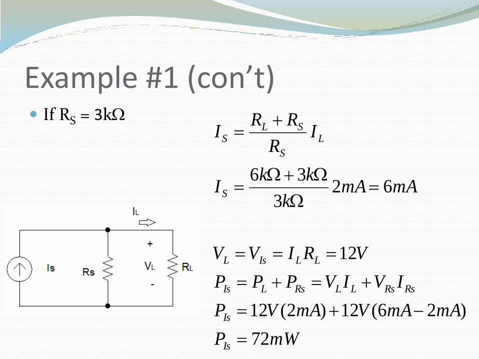
Example #1 (con’t) If RS = 3kW
mWP
mAmAVmAVP
IVIVPPP
VRIVV
mAmAk
kkI
IR
RRI
Is
Is
RsRsLLRsLIs
LLIsL
S
L
S
SLS
72
)26(12)2(12
12
623
36
W
WW
Example #1 (con’t) Current and power that the ideal current source needs to
generate in order to supply the same current and voltage to a load increases as RS decreases. Note: Rs can not be equal to 0W.
The power dissipated by RL is 50% of the power generated by the ideal current source when RS = RL.
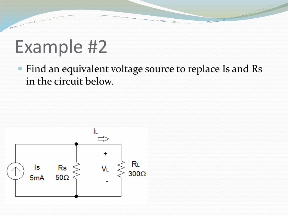
Example #2 Find an equivalent voltage source to replace Is and Rs
in the circuit below.
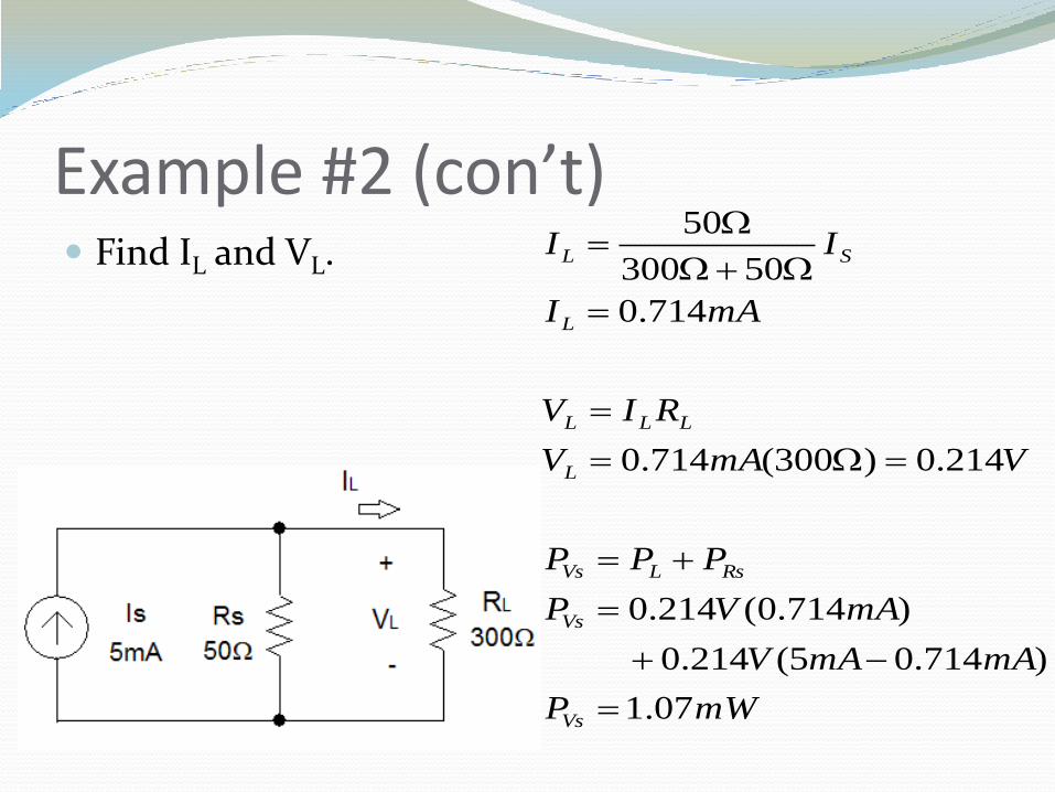
Example #2 (con’t) Find IL and VL.
mWP
mAmAV
mAVP
PPP
VmAV
RIV
mAI
II
Vs
Vs
RsLVs
L
LLL
L
SL
07.1
)714.05(214.0
)714.0(214.0
214.0)300(714.0
714.0
50300
50
W
WW
W
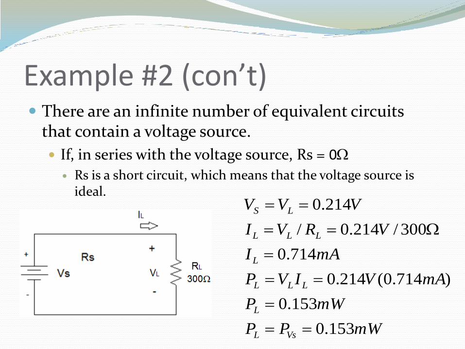
Example #2 (con’t) There are an infinite number of equivalent circuits
that contain a voltage source.
If, in series with the voltage source, Rs = 0W
Rs is a short circuit, which means that the voltage source is ideal.
mWPP
mWP
mAVIVP
mAI
VRVI
VVV
VsL
L
LLL
L
LLL
LS
153.0
153.0
)714.0(214.0
714.0
300/214.0/
214.0
W
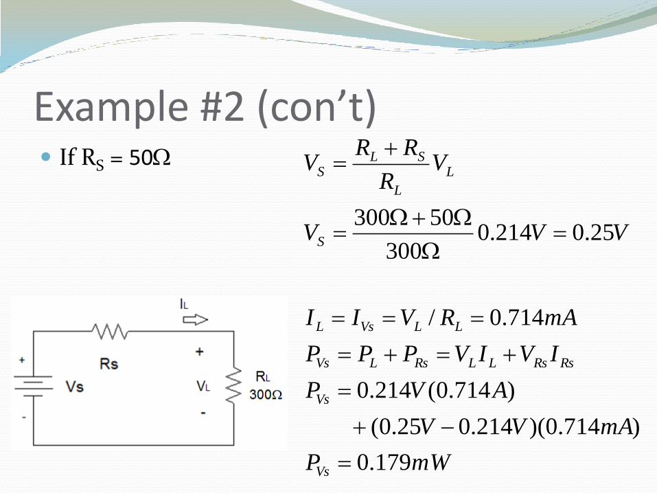
Example #2 (con’t) If RS = 50W
mWP
mAVV
AVP
IVIVPPP
mARVII
VVV
VR
RRV
Vs
Vs
RsRsLLRsLVs
LLVsL
S
L
L
SLS
179.0
)714.0)(214.025.0(
)714.0(214.0
714.0/
25.0214.0300
50300
W
WW
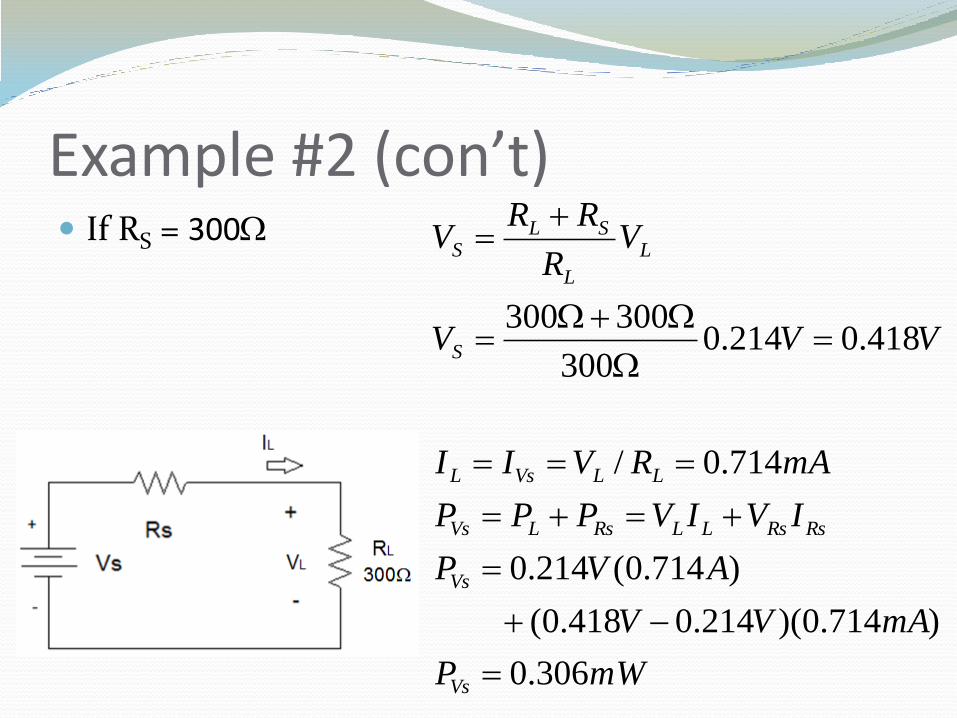
Example #2 (con’t) If RS = 300W
mWP
mAVV
AVP
IVIVPPP
mARVII
VVV
VR
RRV
Vs
Vs
RsRsLLRsLVs
LLVsL
S
L
L
SLS
306.0
)714.0)(214.0418.0(
)714.0(214.0
714.0/
418.0214.0300
300300
W
WW
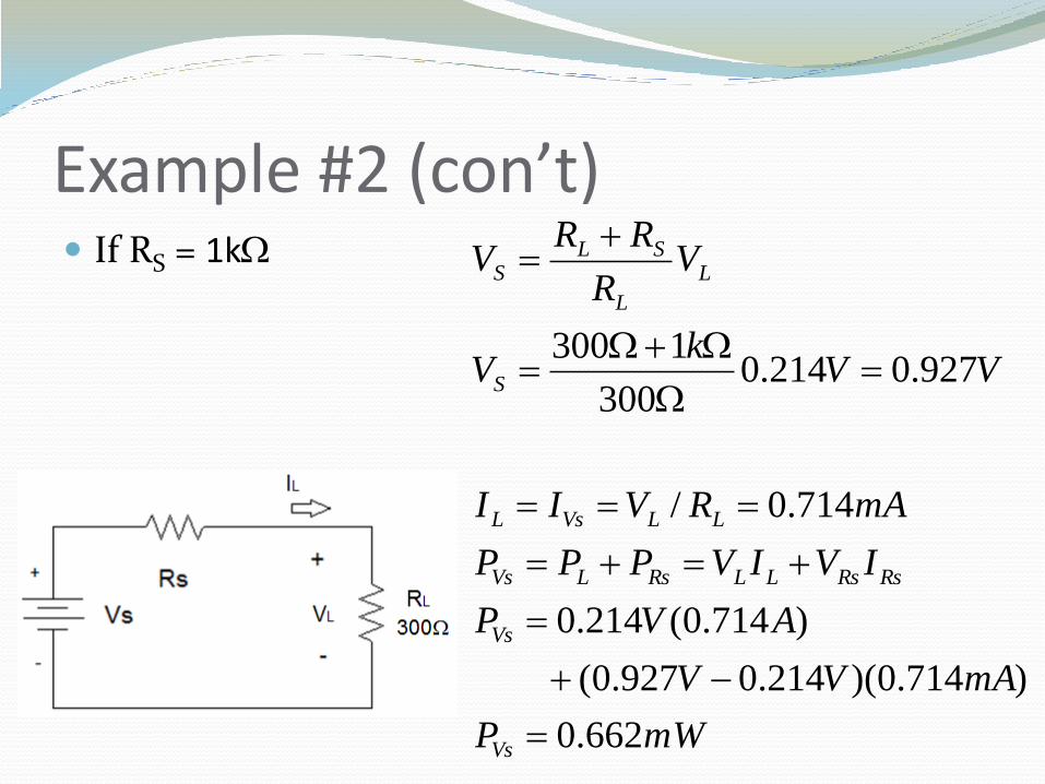
Example #2 (con’t) If RS = 1kW
mWP
mAVV
AVP
IVIVPPP
mARVII
VVk
V
VR
RRV
Vs
Vs
RsRsLLRsLVs
LLVsL
S
L
L
SLS
662.0
)714.0)(214.0927.0(
)714.0(214.0
714.0/
927.0214.0300
1300
W
WW
Example #2 (con’t) Voltage and power that the ideal voltage source needs to
supply to the circuit increases as RS increases. Rs can not be equal to ∞W.
The power dissipated by RL is 50% of the power generated by the ideal voltage source when RS = RL.
Summary An equivalent circuit is a circuit where the voltage
across and the current flowing through a load RL are identical.
As the shunt resistor in a real current source decreases in magnitude, the current produced by the ideal current source must increase.
As the series resistor in a real voltage source increases in magnitude, the voltage produced by the ideal voltage source must increase.
The power dissipated by RL is 50% of the power produced by the ideal source when RL = RS.