Embed Size (px)
Citation preview
Basics of Arduino EPICS Workshop
Arduino (RedBoard), Breadboard, LEDs
Professor John Steele Mechanical Engineering Department
October 23, 2015
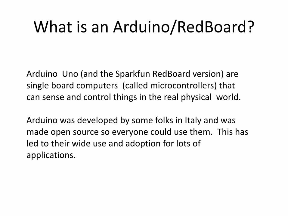
What is an Arduino/RedBoard?
Arduino Uno (and the Sparkfun RedBoard version) are single board computers (called microcontrollers) that can sense and control things in the real physical world.
Arduino was developed by some folks in Italy and was made open source so everyone could use them. This has led to their wide use and adoption for lots of applications.
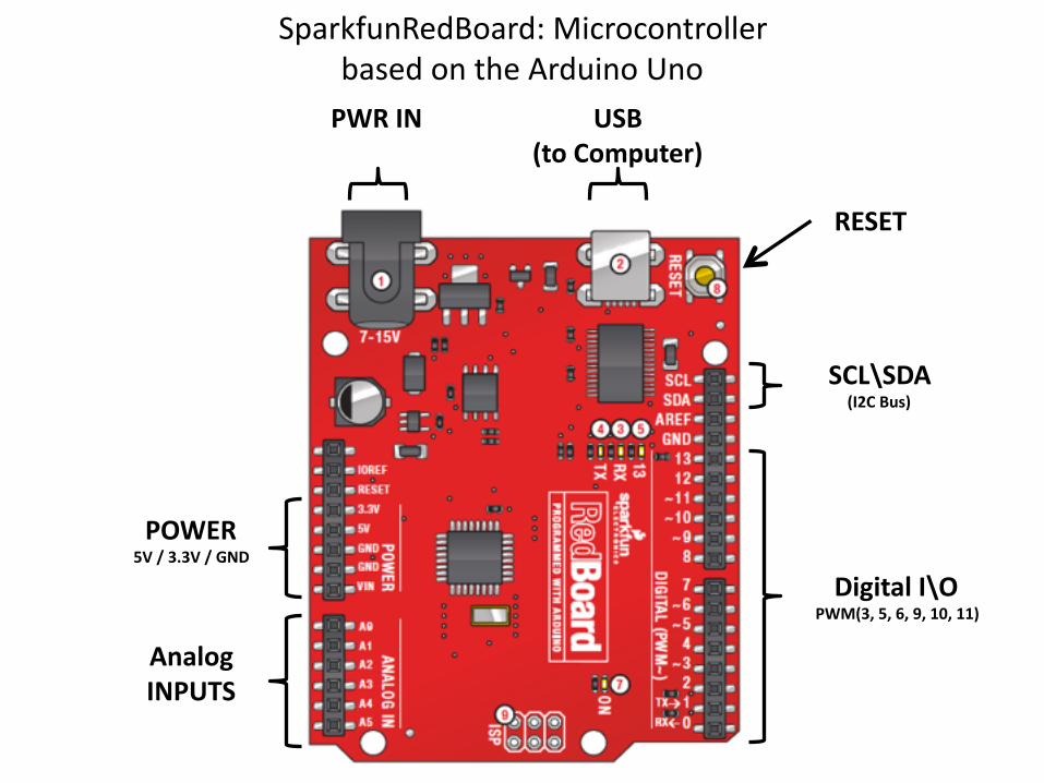
SparkfunRedBoard: Microcontroller based on the Arduino Uno
Analog INPUTS
Digital I\O PWM(3, 5, 6, 9, 10, 11)
PWR IN USB (to Computer)
SCL\SDA (I2C Bus)
POWER 5V / 3.3V / GND
RESET

Arduino Uno
Analog INPUTS
Digital I\O PWM(3, 5, 6, 9, 10, 11)
PWR IN USB (to Computer)
SCL\SDA (I2C Bus)
POWER 5V / 3.3V / GND
RESET
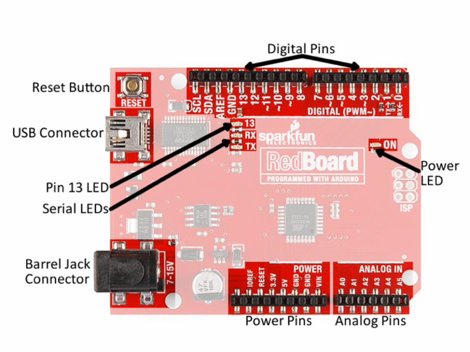

RedBoard (Analog, Digital, Power Header)
The digital pins are the digital inputs and outputs of the Arduino. These are what you connect to buttons, LEDs, sensors, etc. to interface the Arduino with other pieces of hardware. Pins marked with a tilde (~) can also serve as analog outputs, which you can use to dim LEDs or run servo motors (PWM).
There are six analog inputs on the analog header. These pins all have analog-‐to-‐digital converters, which can be used to read in an analog voltage between 0 and 5V. These are useful if you need to read the output of a potentiometer or other analog sensors. All six analog pins can also serve as digital inputs and outputs.
The power header is mostly full of voltage supply pins. These pins are traditionally used as power sources for other pieces of hardware (like LEDs, potentiometers, and other circuits). The ‘3.3V’ and ‘5V’ pins are regulated 3.3V and 5V voltage sources. The ‘GND’ pins are the common ground – the 0V reference for those voltage supplies. ‘VIN’ is the input voltage, it’ll be equal to the voltage of your input supply if you have a wall adapter connected. If nothing is connected to the barrel jack, and you’re powering the board via USB, VIN should be around 5V.

Some Sensors in the Toolbox…..
Push Button Digital Input Switch - Closes or opens circuit
Polarized, needs resistor
Trim potentiometer
Analog Input Variable resistor Also called a Trimpot.
Photoresistor Analog Input Light Dependent Resistor (LDR)
Resistance varies with light.
Relay Digital Output Switch driven by a small signal
Used to control larger voltages
Temp Sensor Analog Input Temp Dependent Resistor
Flex Sensor Analog Input Variable resistor
Soft Trimpot Analog Input Variable resistor Careful of shorts
RGB LED Dig & Analog Output
16,777,216 different colors
Ooh... So pretty.
Name Image Type Function Notes
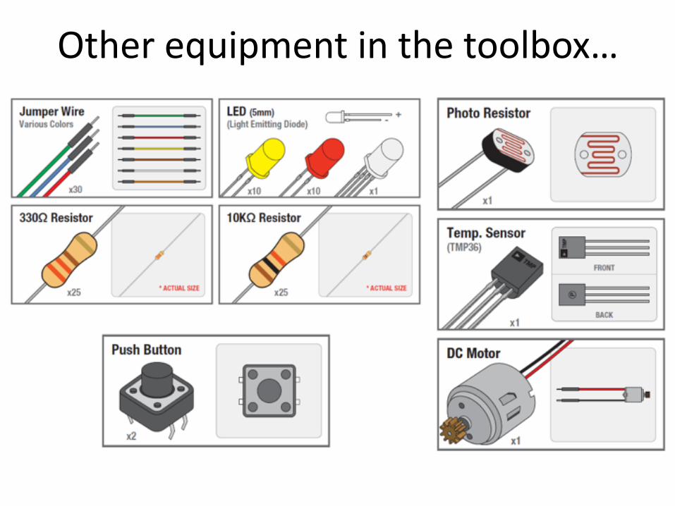
Other equipment in the toolbox…
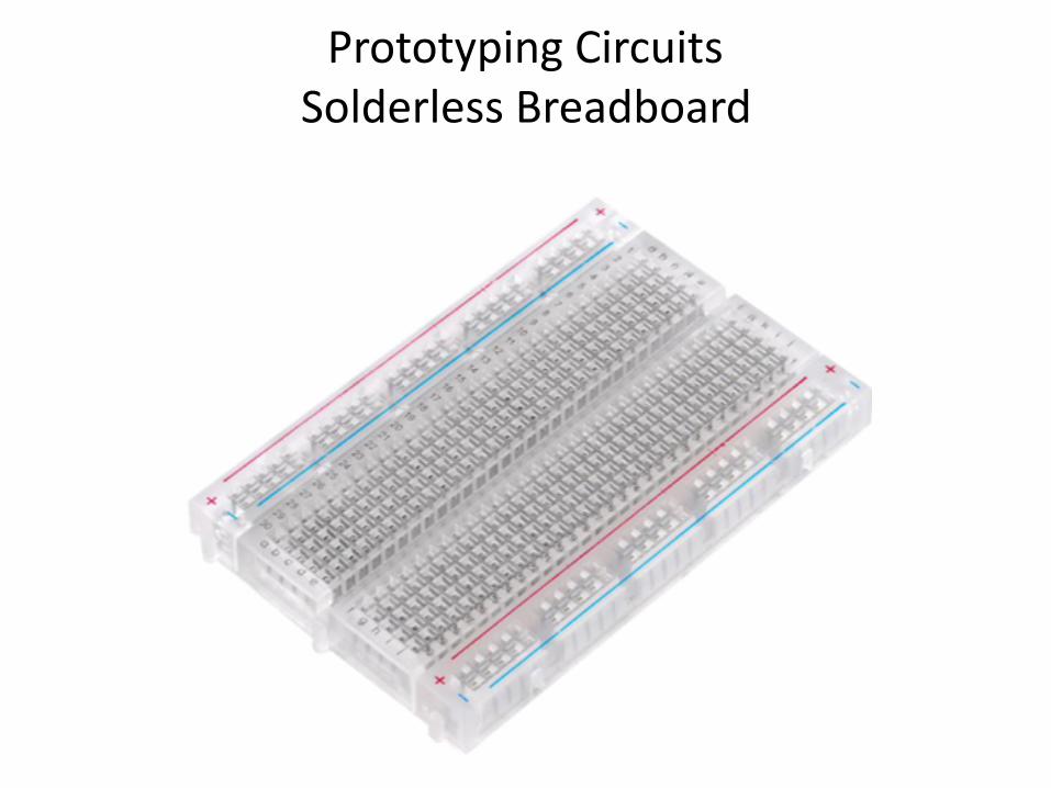
Prototyping Circuits Solderless Breadboard
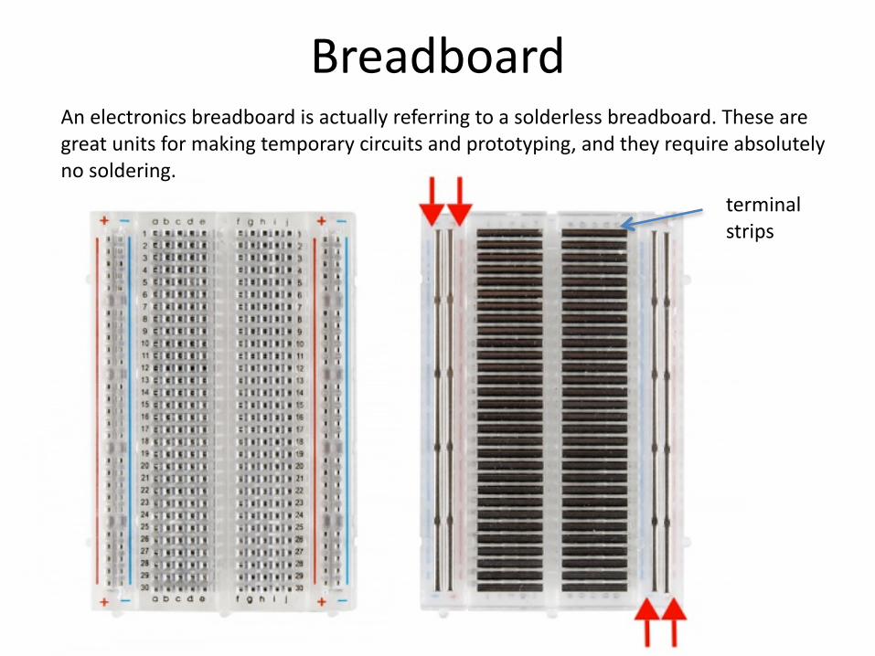
BreadboardAn electronics breadboard is actually referring to a solderless breadboard. These are great units for making temporary circuits and prototyping, and they require absolutely no soldering.
terminal strips
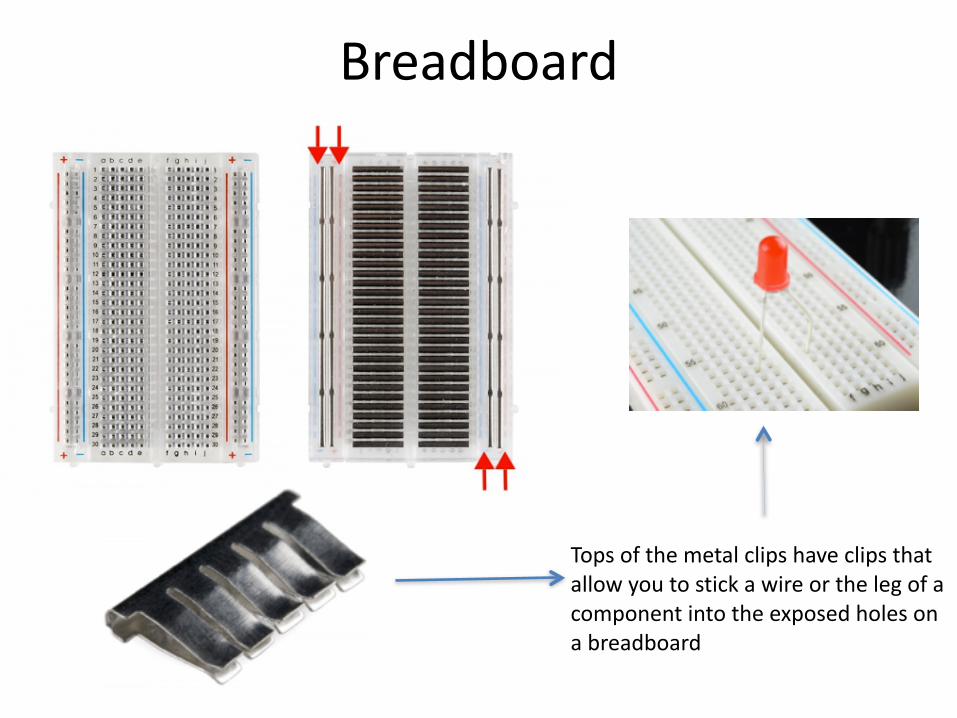
Breadboard
Tops of the metal clips have clips that allow you to stick a wire or the leg of a component into the exposed holes on a breadboard
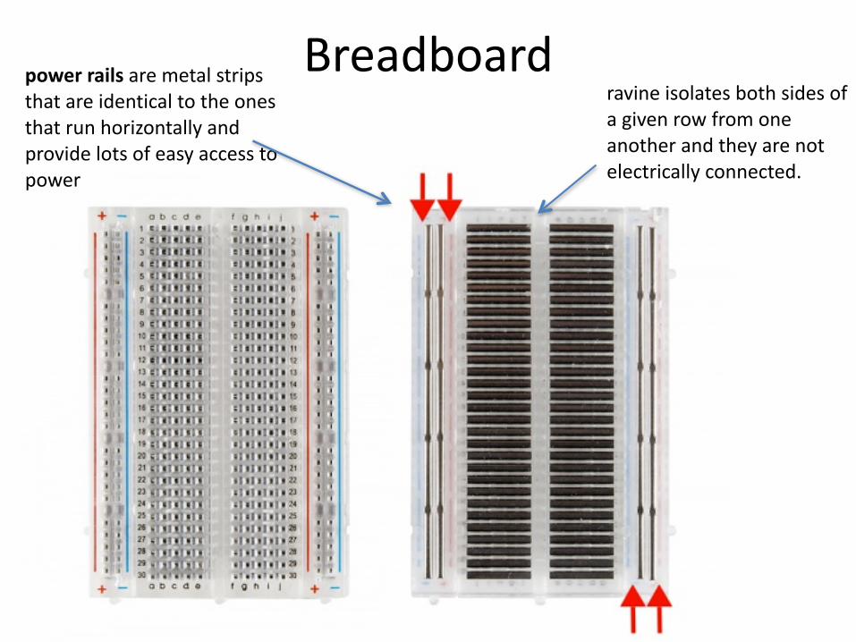
Breadboardravine isolates both sides of a given row from one another and they are not electrically connected.
power rails are metal strips that are identical to the ones that run horizontally and provide lots of easy access to power
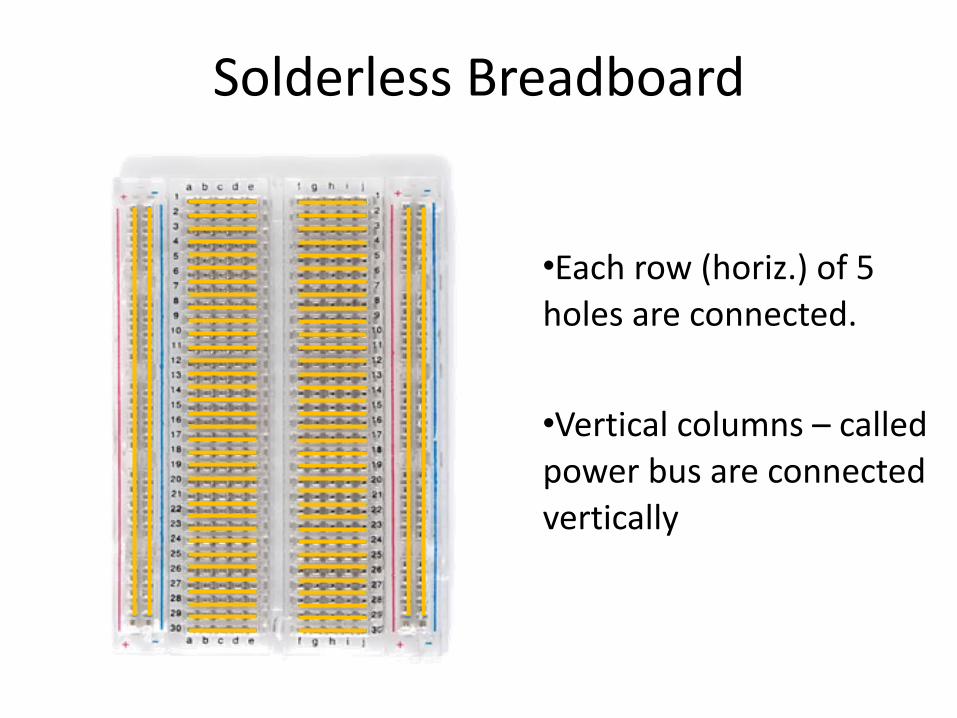
Solderless Breadboard
•Each row (horiz.) of 5 holes are connected.
•Vertical columns – called power bus are connected vertically
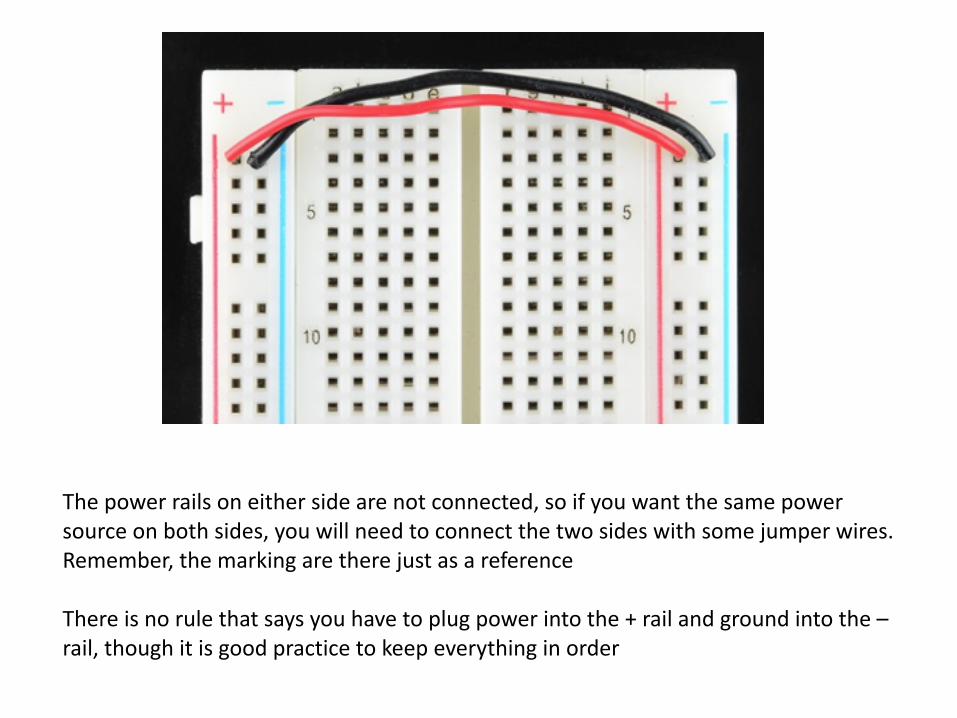
The power rails on either side are not connected, so if you want the same power source on both sides, you will need to connect the two sides with some jumper wires. Remember, the marking are there just as a reference
There is no rule that says you have to plug power into the + rail and ground into the – rail, though it is good practice to keep everything in order
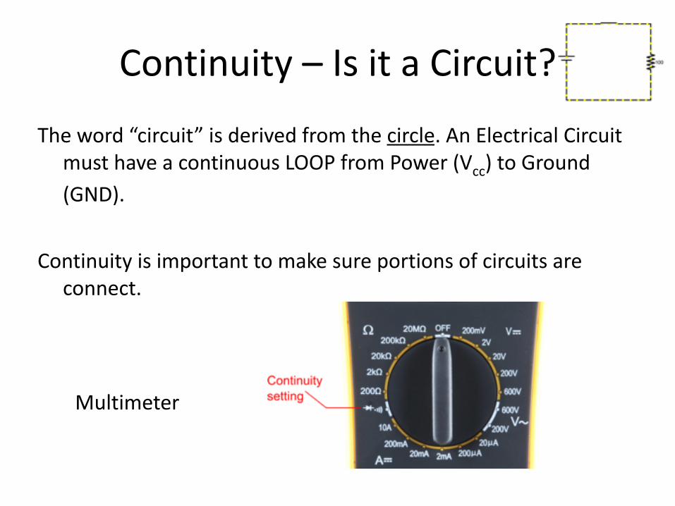
Continuity – Is it a Circuit?
The word “circuit” is derived from the circle. An Electrical Circuit must have a continuous LOOP from Power (Vcc) to Ground (GND).
Continuity is important to make sure portions of circuits are connect.
Multimeter

Measuring Electricity – Voltage
Voltage is a measure of potential electrical energy. A voltage is also called a potential difference – it is measured between two points in a circuit – across a device.
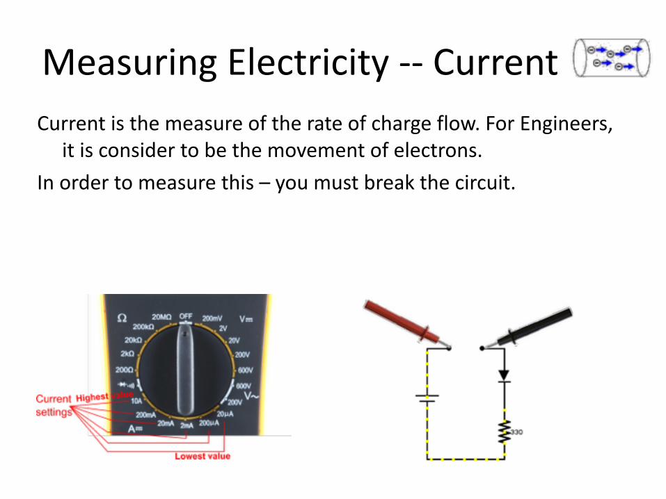
Measuring Electricity -‐-‐ CurrentCurrent is the measure of the rate of charge flow. For Engineers,
it is consider to be the movement of electrons. In order to measure this – you must break the circuit.

Measuring Electricity -‐-‐ ResistanceResistance is the measure of how much opposition to current
flow is in a circuit. Components should be removed entirely from the circuit to
measure resistance. Note the settings on the multi-‐meter. Make sure that you are set for the appropriate range.
Resistance settings
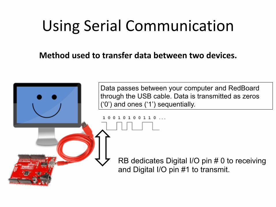
Using Serial Communication
Method used to transfer data between two devices.
RB dedicates Digital I/O pin # 0 to receiving and Digital I/O pin #1 to transmit.
Data passes between your computer and RedBoard through the USB cable. Data is transmitted as zeros (‘0’) and ones (‘1’) sequentially.
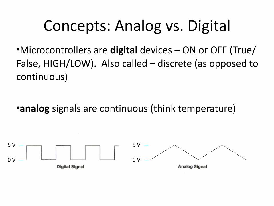
Concepts: Analog vs. Digital•Microcontrollers are digital devices – ON or OFF (True/False, HIGH/LOW). Also called – discrete (as opposed to continuous)
•analog signals are continuous (think temperature)
5 V
0 V
5 V
0 V
PWM
• A few pins on the Arduino allow for us to modify the output to mimic an analog (continuously variable) signal
• This is done using a technique called: • Pulse Width Modulation (PWM)
* Refer to LED fade Demo (PWM)https://www.sparkfun.com/products/12062
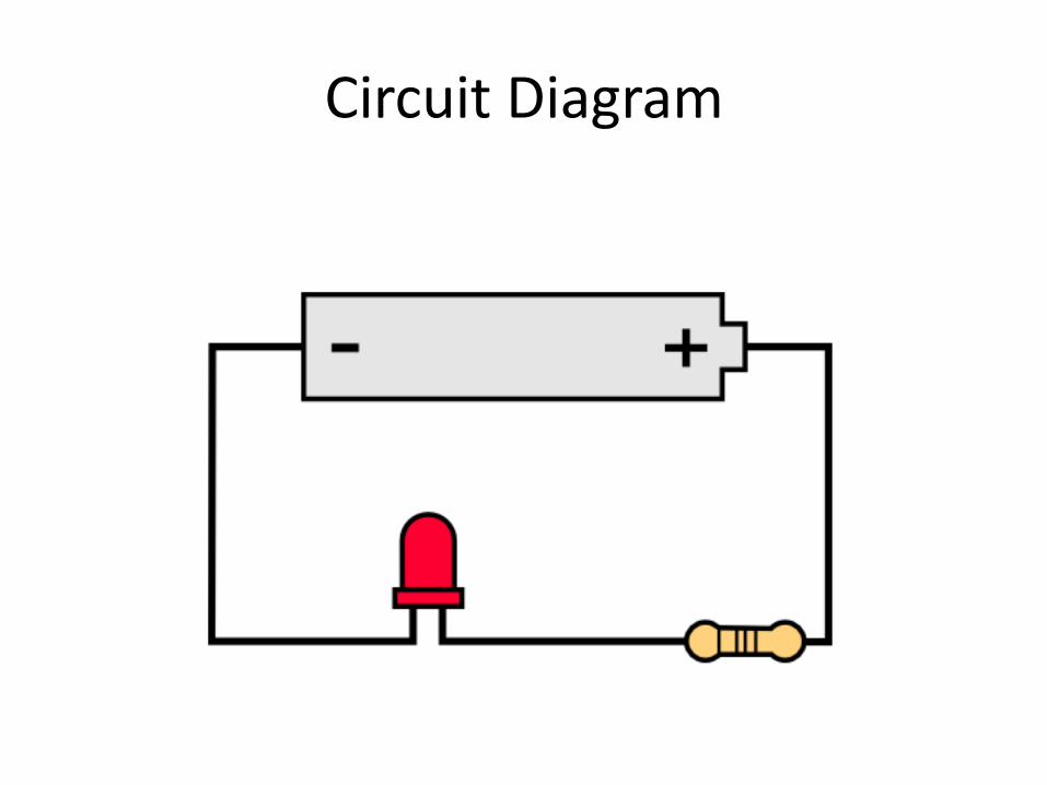
Circuit Diagram

analogWrite()To create an analog signal, the microcontroller uses a technique called PWM. By varying the duty cycle, we can mimic an “average” analog voltage.
Pulse Width Modulation (PWM)
analogWrite(pin,value)

Digital Sensors
• Digital signals are either HIGH (1, true, 5volts) or LOW (0, false, 0 volts)
• Voltage signal for HIGH will be a little less than 5V on your Uno • range is
• Voltage signal for LOW will be about 0 volts on most systems • actually on the ATMEG 328 VoL <= 0.9 volts {for 5V system} • VoH >= 4.2 volts {for 5V system}
digitalWrite() digitalRead()

Using the Breadboard to built a simple circuit
•Use the breadboard to wire up a single LED with a 330 Ohm Resistor (Orange-‐Orange-‐Brown).
Note: the longer leg on the LED is the positive leg and the shorter leg is the negative

Example 1: Watch LED video

Breadboard Circuit
•What happens when you break the circuit? •What if you wanted to add more than one LED?
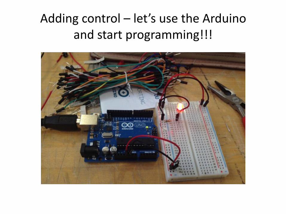
Adding control – let’s use the Arduino and start programming!!!
Concepts: INPUT vs. OUTPUT
Inputs is a signal / information going into the board.
Output is any signal exiting the board.
Concepts: INPUT vs. OUTPUT
Inputs is a signal / information going into the board.
Output is any signal exiting the board.
Examples: Buttons Switches, Light Sensors, Flex Sensors, Humidity Sensors, Temperature Sensors…
Examples: LEDs, DC motor, servo motor, a piezo buzzer, relay, an RGB LED

Code for analog to digital on ‘rolling demo’ example
Remember, your sensor is only outputting a voltage that will be input into the RedBoard and read through the program you created. All sensors output a voltage, just some have digital and some have analog signals.
Getting Started with the RedBoard
• Install the Arduino IDE • Go to arduino.cc
• Download