Embed Size (px)
Citation preview

1©2019 LINKS
BASICS ON GNSS RECEIVERS
Gabriella Povero
Navigation Technologies
GNSS Training
AIT, Bangkok
14 -18 January 2019
2©2019 LINKS
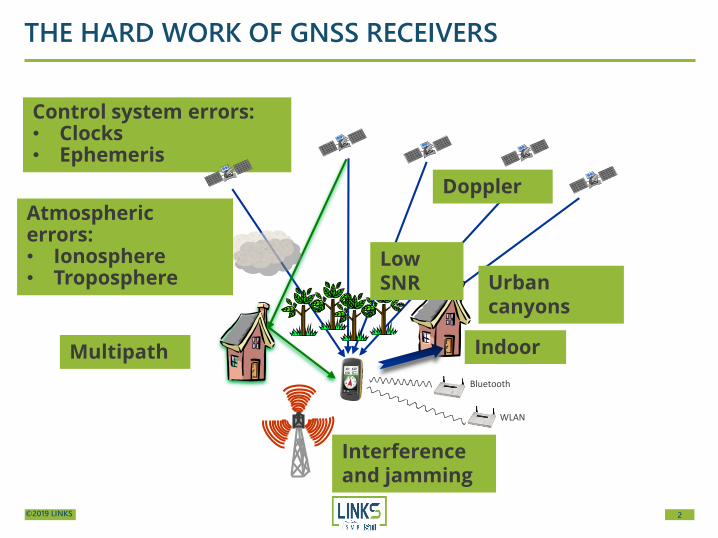
Control system errors:• Clocks• Ephemeris
THE HARD WORK OF GNSS RECEIVERS
Multipath
Interferenceand jamming
Bluetooth
WLAN
Atmospheric errors:• Ionosphere• Troposphere
Doppler
Low SNR
Indoor
Urban canyons

3©2019 LINKS
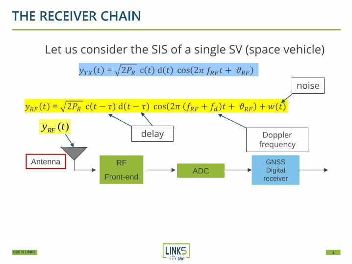
THE RECEIVER CHAIN
Let us consider the SIS of a single SV (space vehicle)
Antenna RF
Front-endADC
GNSS
Digital
receiver
)(tyRF
𝑦𝑇𝑋 𝑡 = 2𝑃𝑅 c 𝑡 d 𝑡 cos 2𝜋 𝑓𝑅𝐹𝑡 + 𝜗𝑅𝐹
𝑦𝑅𝐹 𝑡 = 2𝑃𝑅 c 𝑡 − 𝜏 d 𝑡 − 𝜏 cos 2𝜋 𝑓𝑅𝐹 + 𝑓𝑑 𝑡 + 𝜗𝑅𝐹 +𝑤(𝑡)
4©2019 LINKS
THE RECEIVER CHAIN
Let us consider the SIS of a single SV (space vehicle)
Antenna RF
Front-endADC
GNSS
Digital
receiver
)(tyRF
𝑦𝑇𝑋 𝑡 = 2𝑃𝑅 c 𝑡 d 𝑡 cos 2𝜋 𝑓𝑅𝐹𝑡 + 𝜗𝑅𝐹
𝑦𝑅𝐹 𝑡 = 2𝑃𝑅 c 𝑡 − 𝜏 d 𝑡 − 𝜏 cos 2𝜋 𝑓𝑅𝐹 + 𝑓𝑑 𝑡 + 𝜗𝑅𝐹 +𝑤(𝑡)
delay Doppler frequency
noise
5©2019 LINKS
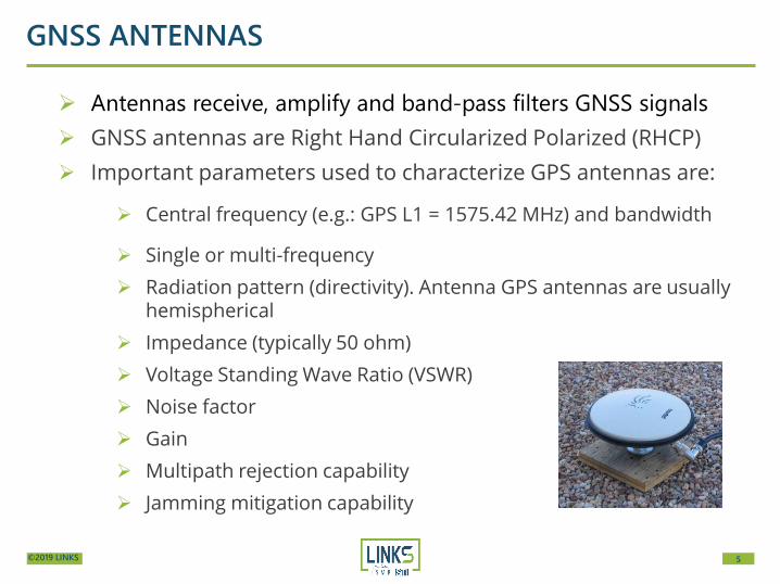
GNSS ANTENNAS
➢ Antennas receive, amplify and band-pass filters GNSS signals
➢ GNSS antennas are Right Hand Circularized Polarized (RHCP)
➢ Important parameters used to characterize GPS antennas are:
➢ Central frequency (e.g.: GPS L1 = 1575.42 MHz) and bandwidth
➢ Single or multi-frequency
➢ Radiation pattern (directivity). Antenna GPS antennas are usuallyhemispherical
➢ Impedance (typically 50 ohm)
➢ Voltage Standing Wave Ratio (VSWR)
➢ Noise factor
➢ Gain
➢ Multipath rejection capability
➢ Jamming mitigation capability
6©2019 LINKS
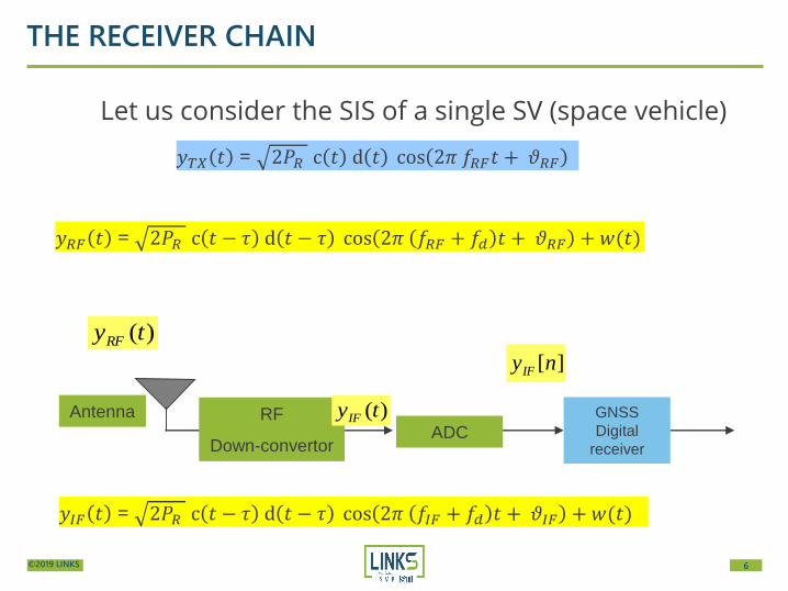
THE RECEIVER CHAIN
Let us consider the SIS of a single SV (space vehicle)
][))(2cos()()(2][ )( nwnTffnTdnTcPny IFIFsdIFss
b
RIF
𝑦𝑇𝑋 𝑡 = 2𝑃𝑅 c 𝑡 d 𝑡 cos 2𝜋 𝑓𝑅𝐹𝑡 + 𝜗𝑅𝐹
𝑦𝑅𝐹 𝑡 = 2𝑃𝑅 c 𝑡 − 𝜏 d 𝑡 − 𝜏 cos 2𝜋 𝑓𝑅𝐹 + 𝑓𝑑 𝑡 + 𝜗𝑅𝐹 +𝑤(𝑡)
Antenna RF
Down-convertorADC
GNSS
Digital
receiver
)(tyIF
)(tyRF
𝑦𝐼𝐹 𝑡 = 2𝑃𝑅 c 𝑡 − 𝜏 d 𝑡 − 𝜏 cos 2𝜋 𝑓𝐼𝐹 + 𝑓𝑑 𝑡 + 𝜗𝐼𝐹 +𝑤(𝑡)
7©2019 LINKS
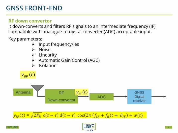
GNSS FRONT-END
RF down convertorIt down-converts and filters RF signals to an intermediate frequency (IF) compatible with analogue-to-digital converter (ADC) acceptable input.
Key parameters:➢ Input frequency/ies➢ Noise➢ Linearity➢ Automatic Gain Control (AGC)➢ Isolation
Antenna RF
Down-convertorADC
GNSS
Digital
receiver
)(tyIF
)(tyRF
𝑦𝐼𝐹 𝑡 = 2𝑃𝑅 c 𝑡 − 𝜏 d 𝑡 − 𝜏 cos 2𝜋 𝑓𝐼𝐹 + 𝑓𝑑 𝑡 + 𝜗𝐼𝐹 +𝑤(𝑡)

8©2019 LINKS
ANALOG TO DIGITAL CONVERTER (ADC)
From Analog DeviceAD9288
Important parameters used to characterize the ADC are:
➢ # of bits: GNSS receivers works well with a low number of bits per samples (1,2, 1.5, 4bits). Higher number of bits (8 bits) used for specific applications (e.g.: interferencedetection)
➢ Analog input range: defines the voltage range in input. Used in the design of thefront end gain
➢ Maximum sampling frequency: depends on the device (e.g.: 60, 80, 100 Msps)
➢ Analog input bandwidth: Determine the maximum frequency of the signal that canbe processed by the device

9©2019 LINKS
THE RECEIVER CHAIN
Let us consider the SIS of a single SV (space vehicle)
Antenna RF
Front-endADC
GNSS
Digital
receiver
)(tyIF
)(tyRF
][))(2cos()()(2][ )( nwnTffnTdnTcPny IFIFsdIFss
b
RIF
][))(2cos()()(2][ )( nwnTffnTdnTcPny IFIFsdIFss
b
RIF
𝑦𝑇𝑋 𝑡 = 2𝑃𝑅 c 𝑡 d 𝑡 cos 2𝜋 𝑓𝑅𝐹𝑡 + 𝜗𝑅𝐹
𝑦𝑅𝐹 𝑡 = 2𝑃𝑅 c 𝑡 − 𝜏 d 𝑡 − 𝜏 cos 2𝜋 𝑓𝑅𝐹 + 𝑓𝑑 𝑡 + 𝜗𝑅𝐹 +𝑤(𝑡)
delay Doppler frequency
10©2019 LINKS
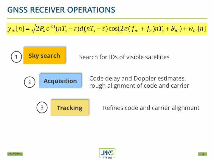
GNSS RECEIVER OPERATIONS
Acquisition
Sky search
Tracking Refines code and carrier alignment
Search for IDs of visible satellites
Code delay and Doppler estimates, rough alignment of code and carrier
1
2
3
][))(2cos()()(2][ )( nwnTffnTdnTcPny IFIFsdIFss
b
RIF
11©2019 LINKS
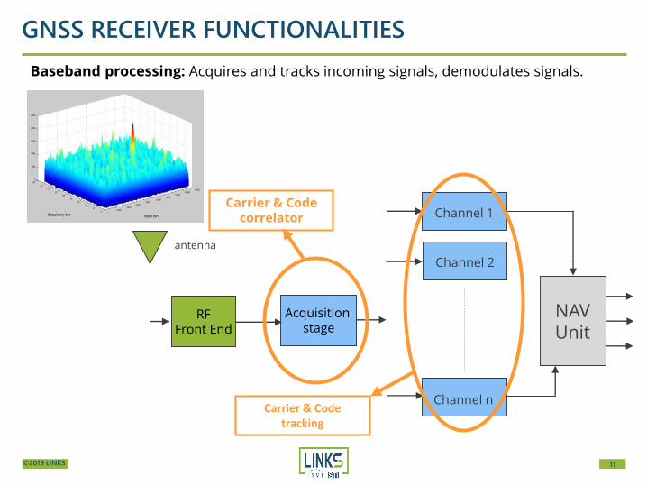
RFFront End
antenna
Channel 1
Channel 2
Channel n
NAVUnit
Carrier & Code tracking
GNSS RECEIVER FUNCTIONALITIES
Acquisitionstage
Carrier & Code correlator
Baseband processing: Acquires and tracks incoming signals, demodulates signals.
12©2019 LINKS
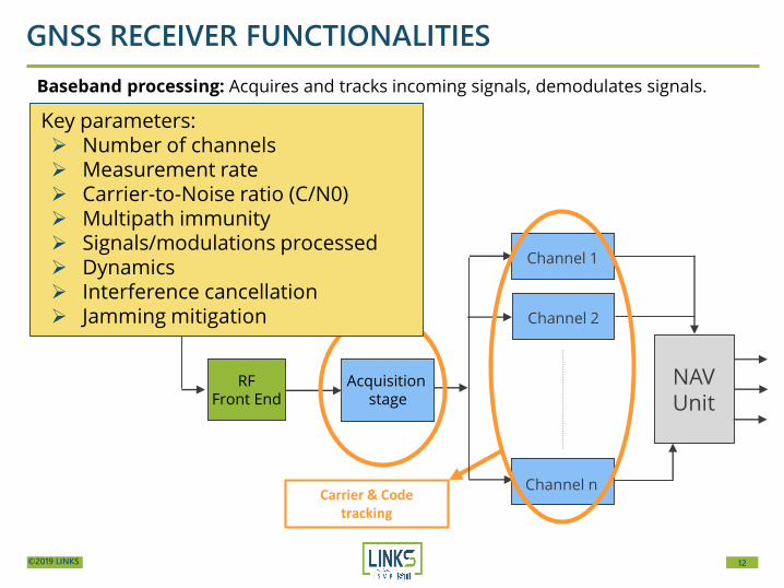
RFFront End
antenna
Channel 1
Channel 2
Channel n
NAVUnit
Carrier & Code tracking
GNSS RECEIVER FUNCTIONALITIES
Acquisitionstage
Carrier & Code correlator
Baseband processing: Acquires and tracks incoming signals, demodulates signals.
Key parameters: ➢ Number of channels ➢ Measurement rate➢ Carrier-to-Noise ratio (C/N0)➢ Multipath immunity➢ Signals/modulations processed➢ Dynamics➢ Interference cancellation➢ Jamming mitigation

13©2019 LINKS
Computation Usually the PVT
Integration with external
info
Not present in all receivers
HMI Not present in all receivers
5
6
7
GNSS RECEIVER OPERATIONS
Measurements Pseudorange and data demodulation4
14©2019 LINKS
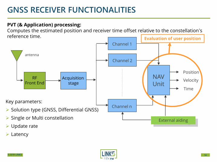
External aiding
RFFront End
antenna
Channel 1
Channel 2
Channel n
NAVUnit
Position
Velocity
Evaluation of user position
Time
GNSS RECEIVER FUNCTIONALITIES
Acquisitionstage
PVT (& Application) processing: Computes the estimated position and receiver time offset relative to the constellation’s reference time.
Key parameters:
➢ Solution type (GNSS, Differential GNSS)
➢ Single or Multi constellation
➢ Update rate
➢ Latency
15©2019 LINKS
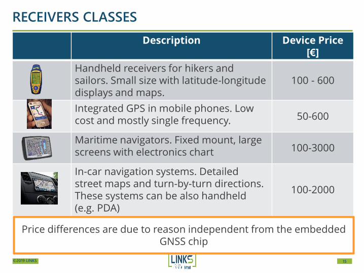
Description Device Price [€]
Handheld receivers for hikers and sailors. Small size with latitude-longitude displays and maps.
100 - 600
Integrated GPS in mobile phones. Low cost and mostly single frequency. 50-600
Maritime navigators. Fixed mount, large screens with electronics chart 100-3000
In-car navigation systems. Detailed street maps and turn-by-turn directions. These systems can be also handheld (e.g. PDA)
100-2000
RECEIVERS CLASSES
Price differences are due to reason independent from the embedded GNSS chip
16©2019 LINKS
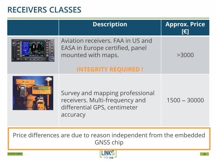
Description Approx. Price [€]
Aviation receivers. FAA in US and EASA in Europe certified, panel mounted with maps.
INTEGRITY REQUIRED !
>3000
Survey and mapping professional receivers. Multi-frequency and differential GPS, centimeter accuracy
1500 – 30000
RECEIVERS CLASSES
Price differences are due to reason independent from the embedded GNSS chip
17©2019 LINKS
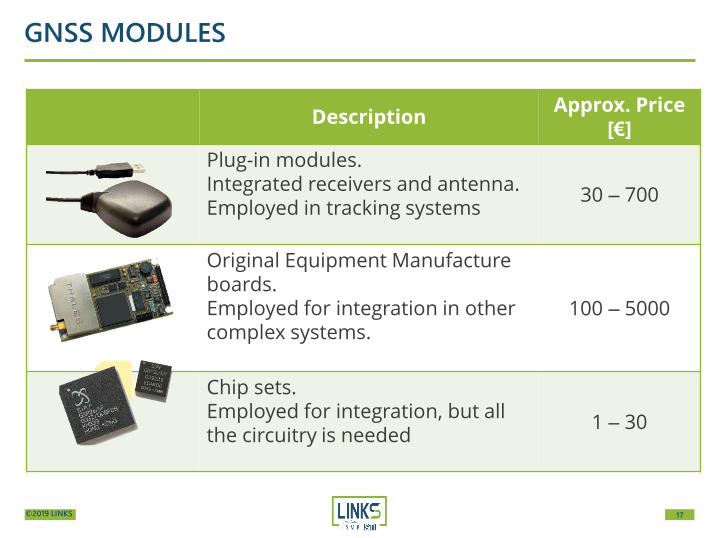
DescriptionApprox. Price
[€]
Plug-in modules. Integrated receivers and antenna. Employed in tracking systems
30 – 700
Original Equipment Manufacture boards. Employed for integration in other complex systems.
100 – 5000
Chip sets. Employed for integration, but all the circuitry is needed
1 – 30
GNSS MODULES

18©2019 LINKS
PROFESSIONAL VS MASS-MARKET RECEIVERS
Raw measurements availability
and configurability
Carrier Phasevs
Code Phase?
Configurability DGNSS … RTK
19©2019 LINKS
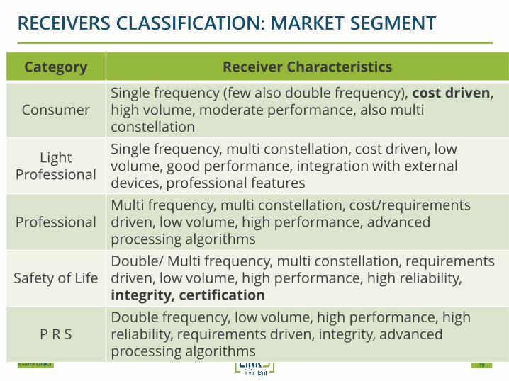
RECEIVERS CLASSIFICATION: MARKET SEGMENT
Category Receiver Characteristics
Consumer Single frequency (few also double frequency), cost driven, high volume, moderate performance, also multi constellation
Light Professional
Single frequency, multi constellation, cost driven, low volume, good performance, integration with external devices, professional features
ProfessionalMulti frequency, multi constellation, cost/requirements driven, low volume, high performance, advanced processing algorithms
Safety of LifeDouble/ Multi frequency, multi constellation, requirements driven, low volume, high performance, high reliability, integrity, certification
P R SDouble frequency, low volume, high performance, high reliability, requirements driven, integrity, advanced processing algorithms

20©2019 LINKS
GNSS RX FEATURES
➢ Constellation(s) exploited
➢ Military or civil receiver
➢ PVT update rate
➢ Indoor operations or high multipath environment
➢ Interference mitigation
➢ Dynamic conditions (from static to high dynamics)
➢ DGPS or WAAS/EGNOS capability (RTK input/output)
➢ Storage of log data
➢ Shock and vibration tolerance
➢ Cartographic support
➢ INS integration or dead-
reckoning systems
➢ Integration with COM systems
➢ Portability
➢ Usability
➢ Power consumption
➢ Cost
21©2019 LINKS
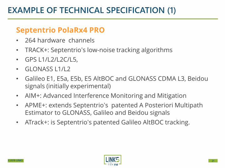
EXAMPLE OF TECHNICAL SPECIFICATION (1)
Septentrio PolaRx4 PRO
• 264 hardware channels
• TRACK+: Septentrio’s low-noise tracking algorithms
• GPS L1/L2/L2C/L5,
• GLONASS L1/L2
• Galileo E1, E5a, E5b, E5 AltBOC and GLONASS CDMA L3, Beidousignals (initially experimental)
• AIM+: Advanced Interference Monitoring and Mitigation
• APME+: extends Septentrio’s patented A Posteriori Multipath Estimator to GLONASS, Galileo and Beidou signals
• ATrack+: is Septentrio’s patented Galileo AltBOC tracking.
22©2019 LINKS
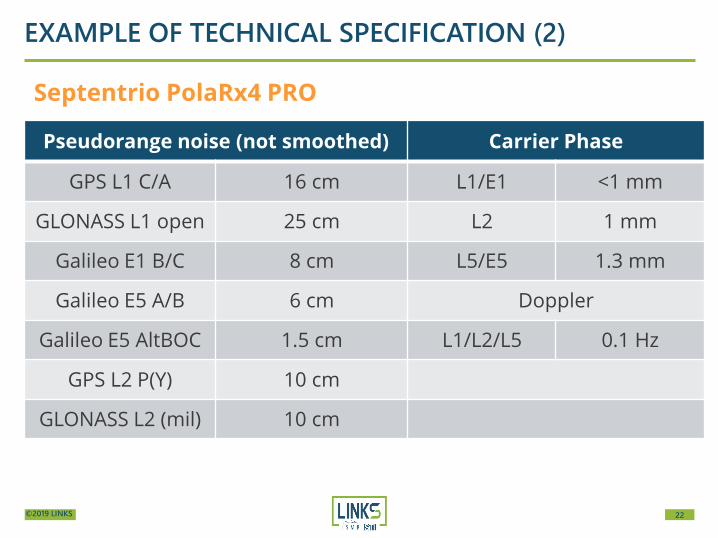
EXAMPLE OF TECHNICAL SPECIFICATION (2)
Septentrio PolaRx4 PRO
Pseudorange noise (not smoothed) Carrier Phase
GPS L1 C/A 16 cm L1/E1 <1 mm
GLONASS L1 open 25 cm L2 1 mm
Galileo E1 B/C 8 cm L5/E5 1.3 mm
Galileo E5 A/B 6 cm Doppler
Galileo E5 AltBOC 1.5 cm L1/L2/L5 0.1 Hz
GPS L2 P(Y) 10 cm
GLONASS L2 (mil) 10 cm
23©2019 LINKS
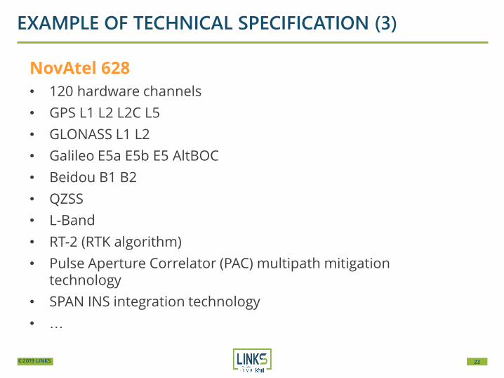
EXAMPLE OF TECHNICAL SPECIFICATION (3)
NovAtel 628
• 120 hardware channels
• GPS L1 L2 L2C L5
• GLONASS L1 L2
• Galileo E5a E5b E5 AltBOC
• Beidou B1 B2
• QZSS
• L-Band
• RT-2 (RTK algorithm)
• Pulse Aperture Correlator (PAC) multipath mitigation technology
• SPAN INS integration technology
• …

24©2019 LINKS
EXAMPLE OF TECHNICAL SPECIFICATION (4)
NovAtel 628
Pseudorange noise (not smoothed) Carrier Phase
GPS L1 C/A 4 cm L1 GPS 0.5 mm
GLONASS L1 open
8 cm L1 GLONASS 1 mm
GPS L2 P(Y) 8 cm L2 1 mm
GPS L2C 8 cm L2C 0.5 mm
GPS L5 3 cm L5 0.5 mm
GLONASS L2 open
8cm
GLONASS L2 mil 8 cm
25©2019 LINKS
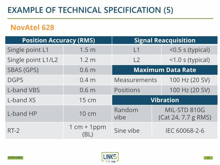
EXAMPLE OF TECHNICAL SPECIFICATION (5)
NovAtel 628
Position Accuracy (RMS) Signal Reacquisition
Single point L1 1.5 m L1 <0.5 s (typical)
Single point L1/L2 1.2 m L2 <1.0 s (typical)
SBAS (GPS) 0.6 m Maximum Data Rate
DGPS 0.4 m Measurements 100 Hz (20 SV)
L-band VBS 0.6 m Positions 100 Hz (20 SV)
L-band XS 15 cm Vibration
L-band HP 10 cmRandom vibe
MIL-STD 810G(Cat 24, 7.7 g RMS)
RT-21 cm + 1ppm
(BL)Sine vibe IEC 60068-2-6
26©2019 LINKS
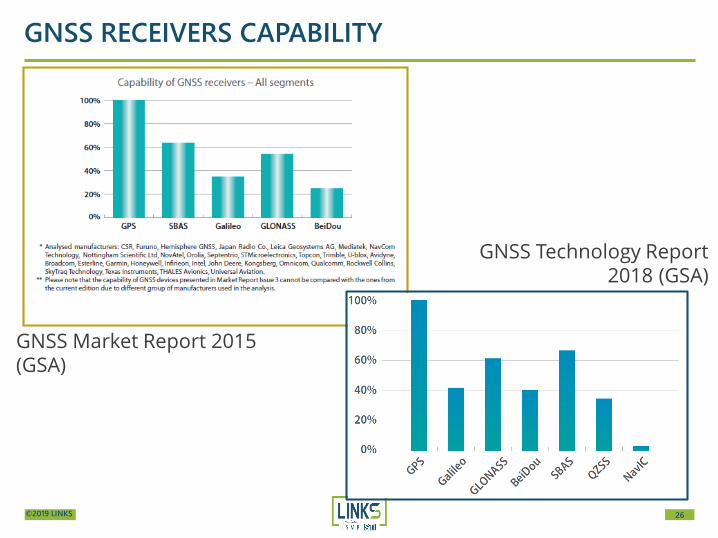
GNSS RECEIVERS CAPABILITY
GNSS Market Report 2015 (GSA)
GNSS Technology Report 2018 (GSA)
27©2019 LINKS
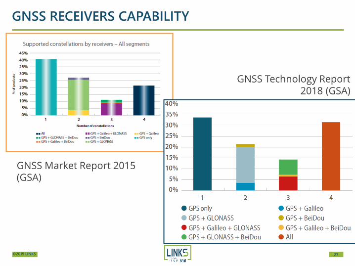
GNSS RECEIVERS CAPABILITY
GNSS Market Report 2015 (GSA)
GNSS Technology Report 2018 (GSA)
28©2019 LINKS
https://www.gsa.europa.eu/system/files/reports/gnss_user_tech_report_2018.pdf

29©2019 LINKS
CONTACT
LINKS FOUNDATION
@linksfoundation
@linksfoundation
linksfoundation
linksfoundation.com
Via Pier Carlo Boggio 61 | 10138 Torino
+(039) 011 2276 150
GABRIELLA POVERO