Embed Size (px)
Citation preview
W W W. P I . W S
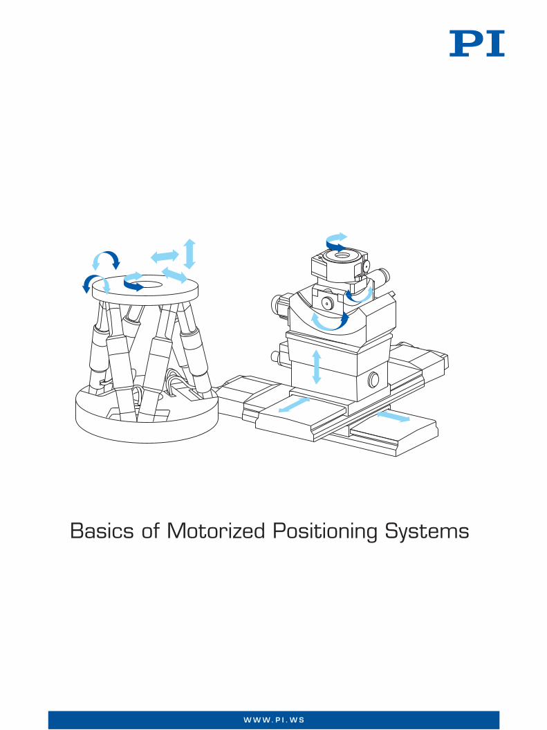
Basics of Motorized Positioning Systems

Basics of Motorized Positioning Systems
Motors and Drives
Linear Drives – Piezo Drives – Rotating Electric Motors – Combinations of Piezo Actuator and Electric Motor
Page 253
Drive Train Elements
Gearheads – Types of Drive Screw
Page 257
Metrology
Indirect Metrology – Direct Metrology – Extended Metrology Concepts
Page 258
Guidings and Bearings
Linear Guides – Air Bearings – Flexure Guides
Page 259
Use in Vacuum
Decisive: Material Selection – Preferred Materials – Mounting in Cleanrooms – Important Factors for Vacuum Stages – Controllers, Amplifiers and Other Electronic Devices – Adapting Stages to Different Classes of Vacuum
Page 261
SMC Controller Technology
Precision Positioning with SMC Controller – Position Control, Velocity and Correction of Position Errors in the Controller
Page 263
Glossary Page 266
M O T O R I Z E D P O S I T I O N I N G S Y S T E M S | W W W. P I . W S
2 5 2
Linear DrivesLinear drives basically allow for unlimited trav-el ranges. They are direct-drive systems; they do not use drive screws or gearheads and are backlash-free. The positioning accuracy of the overall system is only affected by the position measurement and the guides.
Electromagnetic Linear Drives
Linear servo motors are used both for very high and for very low feed velocities. They work precisely in a range from 0.1 μm/s to more than 5 m/s. If combined with air bear-ings, a position resolution down to a few nano-meters is possible.
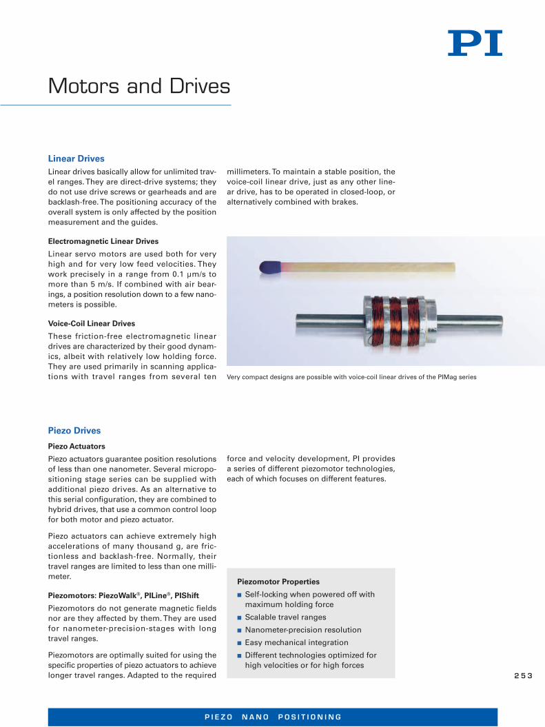
Voice-Coil Linear Drives
These friction-free electromagnetic linear drives are characterized by their good dynam-ics, albeit with relatively low holding force. They are used primarily in scanning applica-tions with travel ranges from several ten
Motors and Drives
milli meters. To maintain a stable position, the voice-coil linear drive, just as any other line-ar drive, has to be operated in closed-loop, or alternatively combined with brakes.
Piezo Drives
Piezo Actuators
Piezo actuators guarantee position resolutions of less than one nanometer. Several micropo-sitioning stage series can be supplied with additional piezo drives. As an alternative to this serial configuration, they are combined to hybrid drives, that use a common control loop for both motor and piezo actuator.
Piezo actuators can achieve extremely high accelerations of many thousand g, are fric-tionless and backlash-free. Normally, their travel ranges are limited to less than one milli-meter.
Piezomotors: PiezoWalk®, PILine®, PIShift
Piezomotors do not generate magnetic fields nor are they affected by them. They are used for nanometer-precision-stages with long travel ranges.
Piezomotors are optimally suited for using the specific properties of piezo actuators to achieve longer travel ranges. Adapted to the required
force and velocity development, PI provides a series of different piezomotor technologies, each of which focuses on different features.
Piezomotor Properties
■ Self-locking when powered off with maximum holding force
■ Scalable travel ranges
■ Nanometer-precision resolution
■ Easy mechanical integration
■ Different technologies optimized for high velocities or for high forces
Very compact designs are possible with voice-coil linear drives of the PIMag series
P I E Z O N A N O P O S I T I O N I N G
2 5 3
DC Motor / Servo Motor
A DC motor with position measurement is
called servo motor. The typical characteristics
of DC servo motors are uniform, vibration-
free operation, a large velocity range and high
torques at low velocity. To benefit in a best pos-
sible way from these properties, a motor con-
troller with proportional, integral and differen-
tial control (PID) and suitable filters is required.
The servo motor has numerous advantages,
such as good dynamics, fast addressing, high
torques at low velocities, reduced heat gen-
eration and low vibration.
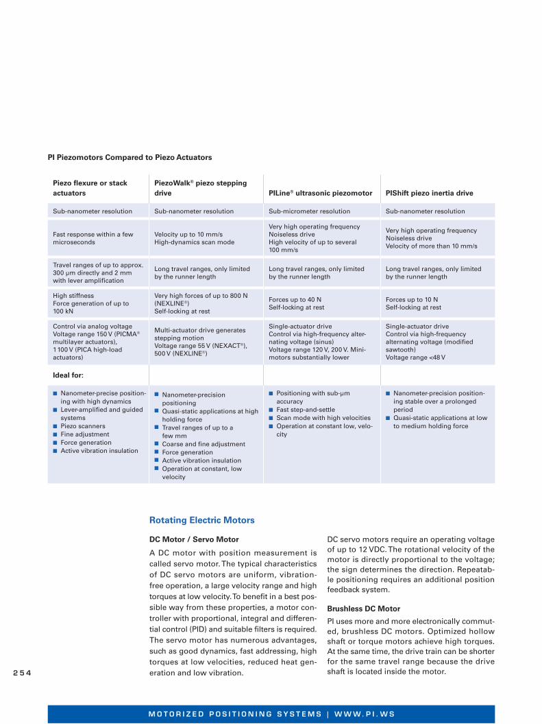
Piezo fl exure or stack actuators
PiezoWalk® piezo stepping drive PILine® ultrasonic piezomotor PIShift piezo inertia drive
Sub-nanometer resolution Sub-nanometer resolution Sub-micrometer resolution Sub-nanometer resolution
Fast response within a few microseconds
Velocity up to 10 mm/sHigh-dynamics scan mode
Very high operating frequencyNoiseless driveHigh velocity of up to several 100 mm/s
Very high operating frequencyNoiseless driveVelocity of more than 10 mm/s
Travel ranges of up to approx. 300 μm directly and 2 mm with lever amplifi cation
Long travel ranges, only limited by the runner length
Long travel ranges, only limited by the runner length
Long travel ranges, only limited by the runner length
High stiffnessForce generation of up to 100 kN
Very high forces of up to 800 N (NEXLINE®)Self-locking at rest
Forces up to 40 NSelf-locking at rest
Forces up to 10 NSelf-locking at rest
Control via analog voltageVoltage range 150 V (PICMA® multilayer actuators), 1 100 V (PICA high-load actuators)
Multi-actuator drive generates stepping motionVoltage range 55 V (NEXACT®), 500 V (NEXLINE®)
Single-actuator driveControl via high-frequency alter-nating voltage (sinus)Voltage range 120 V, 200 V. Mini-motors substantially lower
Single-actuator driveControl via high-frequency alternating voltage (modifi ed sawtooth)Voltage range <48 V
Ideal for:
■ Nanometer-precise position-ing with high dynamics
■ Lever-amplified and guided systems
■ Piezo scanners■ Fine adjustment■ Force generation■ Active vibration insulation
■ Nanometer-precision positioning
■ Quasi-static applications at high holding force
■ Travel ranges of up to a few mm
■ Coarse and fine adjustment■ Force generation ■ Active vibration insulation■ Operation at constant, low
velocity
■ Positioning with sub-μm accuracy
■ Fast step-and-settle■ Scan mode with high velocities■ Operation at constant low, velo-
city
■ Nanometer-precision position-ing stable over a prolonged period
■ Quasi-static applications at low to medium holding force
DC servo motors require an operating voltage of up to 12 VDC. The rotational velocity of the motor is directly proportional to the voltage; the sign determines the direction. Repeatab-le positioning requires an additional position feedback system.
Brushless DC Motor
PI uses more and more electronically commut-ed, brushless DC motors. Optimized hollow shaft or torque motors achieve high torques. At the same time, the drive train can be shorter for the same travel range because the drive shaft is located inside the motor.
Rotating Electric Motors
PI Piezomotors Compared to Piezo Actuators
M O T O R I Z E D P O S I T I O N I N G S Y S T E M S | W W W. P I . W S
2 5 4
ActiveDrive DC Motors
Some of the advantages of DC motor drives are good dynamic performance with a large control range, high torque at low revolutions, low heat dissipation and low vibration with a high position resolution. The cost of a high-performance linear amplifier, however, is gener ally higher than that for a stepper motor.
The ActiveDrive system reduces this cost con-siderably by integrating a PWM (pulse width modulation) driver-amplifier in the motor case. The operating voltage of normally 24 V for ActiveDrive motors is supplied by a separate power supply included in the scope of deliv-ery. The ActiveDrive concept provides several advantages:
■ Increased efficiency by eliminating power losses between the amplifier and motor
■ Reduced cost, more compact system, and improved reliability, because no external driver and cabling are required
■ Elimination of PWM amplifier noise radia-tion by mounting the amplifier and motor together in a single shielded case
Stepper Motor Drives
Contrary to DC motors, stepper motor drives only take up discrete positions in a revolu tion. As these steps have a constant distance, a position may be commanded using the num-ber of steps without any need of a position sensor. Normally, there are 200 to 1 000 full steps in each revolution. The actually achiev-able step width is determined by the stepper motor control, which electronically interpolates up to several hundred thousand microsteps in between the full steps depending on the ver-sion. PI uses smoothly running 2-phase step-p er motors.
Stepper motors have very long lifetimes and, compared to DC motors, are especially suited for applications with reduced dynamics and in a vacuum. A mechanical damper on the motor shaft, which also works as handwheel, enhan-ces running smoothness.
To maintain a position, stepper motors without self-locking gearhead need to be energized continually. This may cause a position jitter between the steps and generate heat.
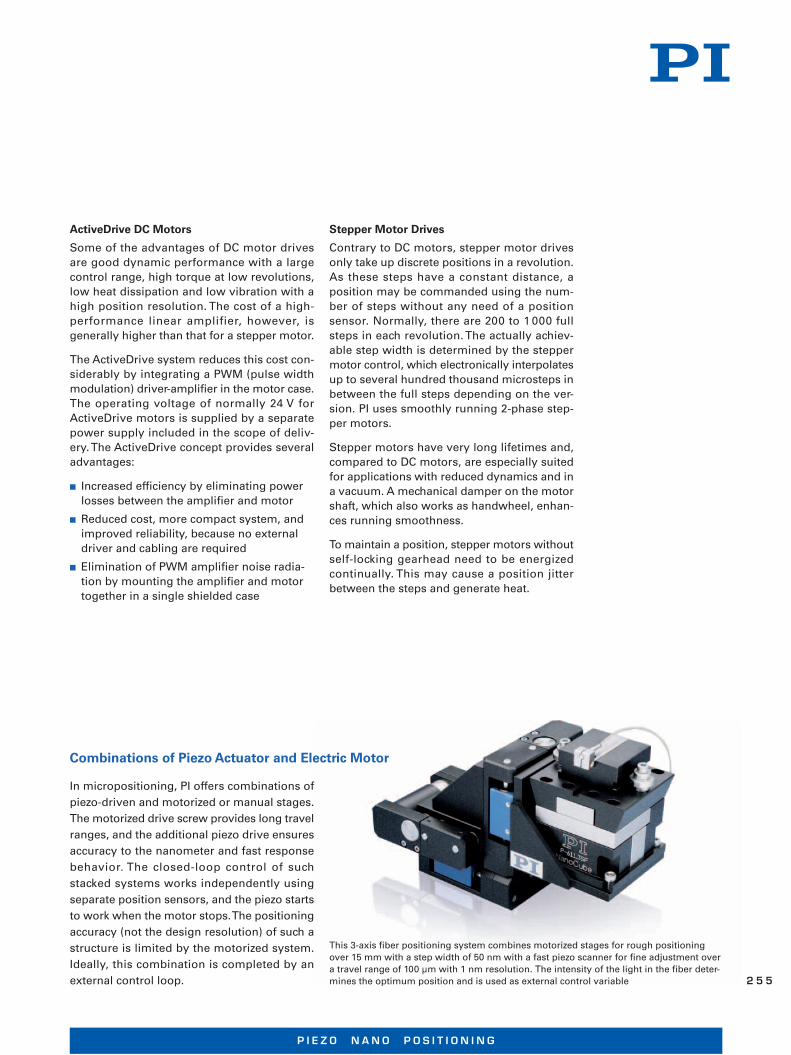
In micropositioning, PI offers combinations of
piezo-driven and motorized or manual stages.
The motorized drive screw provides long travel
ranges, and the additional piezo drive ensures
accuracy to the nanometer and fast response
behavior. The closed-loop control of such
stacked systems works independently using
separate position sensors, and the piezo starts
to work when the motor stops. The positioning
accuracy (not the design resolution) of such a
structure is limited by the motorized system.
Ideally, this combination is completed by an
external control loop.
Combinations of Piezo Actuator and Electric Motor
This 3-axis fiber positioning system combines motorized stages for rough positioning over 15 mm with a step width of 50 nm with a fast piezo scanner for fine adjustment over a travel range of 100 μm with 1 nm resolution. The intensity of the light in the fiber deter-mines the optimum position and is used as external control variable
P I E Z O N A N O P O S I T I O N I N G
2 5 5

Hybrid Concept with Single Higher-Level Posi-tion Measurement and Closed-Loop Control
In hybrid drives, the moving platform is decoupled from the motorized drive train by means of a highly stiff piezo actuator as well as backlash-free and frictionless flexure joints. In positioning mode, settling to a few nanome-ters only takes a few milliseconds, and mini-mal increments in the range of the encoder resolution can be reliably executed. In dynamic operation, the piezo actuators guarantee a very constant velocity by compensating the irregu-larities in the motion of the motorized drive. Stick-slip effects when reaching the position or backlash can so be compensated for.
The closed-loop control for both motion systems use the same high-resolution posi-tion sensor. The result is a motion system with hundreds of millimeters travel but with the precision of a piezo-based nanopositioner.The resolution and the positioning accuracy depend on the choice of the position sensor. PI hybrid systems currently use optical linear encoders with a resolution of 2 nm.
Hybrid stages are particularly suited for applica tions that need high accuracy for measuring a position and returning to it, or for surface inspection and metrology if you want to reach a target position accurately to the nanometer.
Schematic view of the hybrid drive. The common closed-loop control of the motor (blue) and the piezo actuator (yellow) with a single high-resolution linear encoder (green) allows for extremely constant velocity and high positioning accuracy
Feed over 1 mm with hybrid stage, velocity 100 μm/s. The deviation from the commanded trajectory is less than 10 nm
Hybridtion Me
In hybdecoupmeansas backIn positters onmal incresolutoperaticonstalarities
Schematic view of the hybrid drive. The common closed-loop control of the motor (blue)and the piezo actuator (yellow) with a single high-resolution linear encoder (green)
M O T O R I Z E D P O S I T I O N I N G S Y S T E M S | W W W. P I . W S
2 5 6
Drive Train Elements
GearheadGearheads are used between motor and drive screw; they improve position resolution and torque. Most models use preloaded gearheads to eliminate backlash.
LeadscrewsLeadscrews can provide very high resolu tions and very smooth motion. A leadscrew drive consists of a motor-driven screw with a nut coupled to the moving platform of the stage. The nut can be spring-preloaded to reduce backlash. They have higher friction than recircu-lating ball screws so that they are self-locking; on the other hand, however, this has an effect on velocity, motor power and lifetime. Typi-cal leadscrews have a pitch between 0.4 and 0.5 mm/revolution, up to 1 mm/revolution for longer travel ranges.
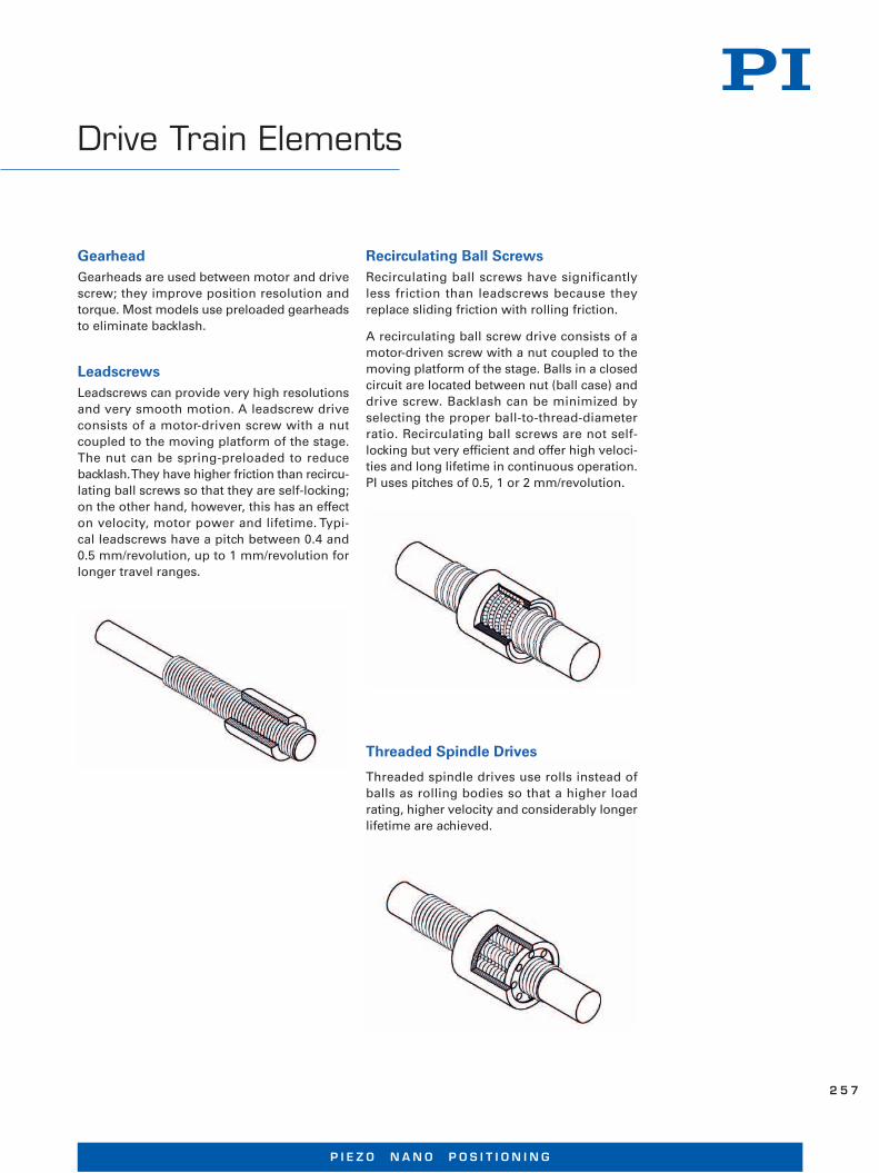
Recirculating Ball ScrewsRecirculating ball screws have significantly less friction than leadscrews because they replace sliding friction with rolling friction.
A recirculating ball screw drive consists of a motor-driven screw with a nut coupled to the moving platform of the stage. Balls in a closed circuit are located between nut (ball case) and drive screw. Backlash can be minimized by select ing the proper ball-to-thread-diameter ratio. Recirculating ball screws are not self-locking but very efficient and offer high veloci-ties and long lifetime in continuous operation. PI uses pitches of 0.5, 1 or 2 mm/revolution.
Threaded Spindle Drives
Threaded spindle drives use rolls instead of balls as rolling bodies so that a higher load rating, higher velocity and considerably longer lifetime are achieved.
P I E Z O N A N O P O S I T I O N I N G
2 5 7
Metrology
Extended Metrology Concepts
Absolute Encoders
Absolute encoders deliver additional informa-tion about the absolute position of the moving platform.
Parallel Metrology
Position sensor configuration for multi-axis parallel-kinematic systems, in which all sensors measure the position between base plate and moving platform. It is essential that all motions that differ from the defined trajec-tory are detected and controlled. This means that position crosstalk of individual axes of all actuators can be compensated ("active trajec-tory control") which requires highly complex control algorithms.
Serial Metrology
Position sensor configuration for multi-axis systems, in which some sensors measure the position between two moving platforms. Advantages are an easy integration in a serial-kinematics system and an easy control con-cept. Guiding errors with position crosstalk of the platforms in between cannot be compen-sat ed.
Tachometer
Tachometers are used for measuring and controlling velocity. Alternatively to a direct measurement, the time course of the posi tion data from the encoder can also be used for velocity control.
Either rotary or linear optical encoders are used as position feedback sensors.
Indirect MetrologyPosition sensor configuration with indirect measurement of the platform motion. Most often, the sensor is integrated in the drive train, for example, by means of a rotary en -coder on the motor shaft. The advantage is an easier attachment of the sensor. Backlash and mechanical play, however, affect the measure-ment result.
Rotary Encoder
A rotary encoder is implemented at a rotating point in the drive train, e.g. the motor shaft. To determine the relative position, the control-ler counts the encoder signals (impulses). To measure an absolute position, a limit switch or reference point switch signal must be used as reference. A typical step width of rotary en coders is approx. 0.1 μm.
Direct MetrologyNoncontact linear optical encoders mea sure the actual position with utmost accuracy directly on the moving platform (direct metro-logy). Errors in the drive train, such as nonli-nearity, mechanical play and elastic deforma-tion, are not considered. With linear encoders a resolution down to the nanometer range can be achieved.
M O T O R I Z E D P O S I T I O N I N G S Y S T E M S | W W W. P I . W S
2 5 8
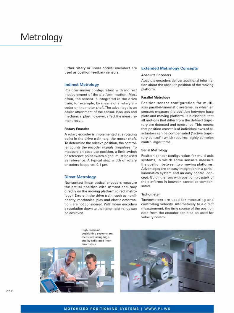
High-precision positioning systems are measured using high-quality calibrated inter-ferometers
Linear Ball Bearing
The balls run in a brass cage and are preload ed with regard to the hardened precision guiding shafts. Exact tolerances between guiding and bearing are necessary for zero backlash and low friction. Load capacity is limited.
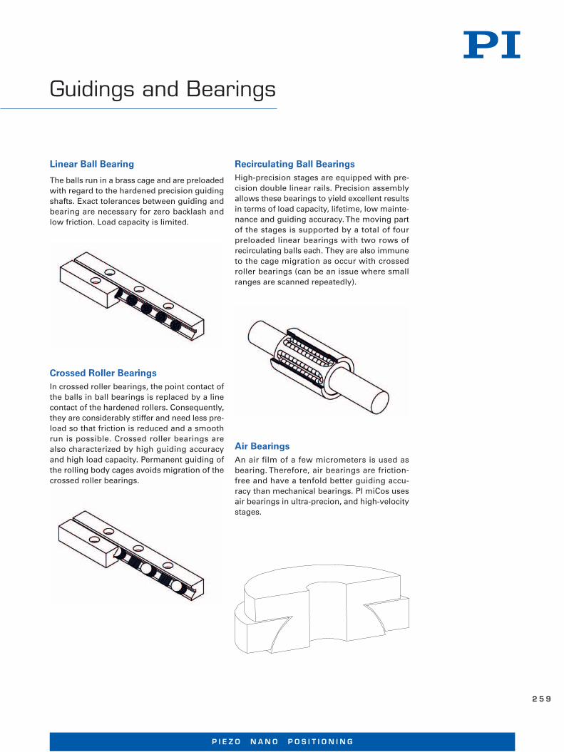
Recirculating Ball BearingsHigh-precision stages are equipped with pre-cision double linear rails. Precision assembly allows these bearings to yield excellent results in terms of load capacity, lifetime, low mainte-nance and guiding accuracy. The moving part of the stages is supported by a total of four preloaded linear bearings with two rows of recirculating balls each. They are also im mune to the cage migration as occur with crossed roller bearings (can be an issue where small ranges are scanned repeatedly).
Crossed Roller BearingsIn crossed roller bearings, the point contact of the balls in ball bearings is replaced by a line contact of the hardened rollers. Consequently, they are considerably stiffer and need less pre-load so that friction is reduced and a smooth run is possible. Crossed roller bearings are also characterized by high guiding accuracy and high load capacity. Permanent guiding of the rolling body cages avoids migration of the crossed roller bearings.
Guidings and Bearings
Air BearingsAn air film of a few micrometers is used as bearing. Therefore, air bearings are friction-free and have a tenfold better guiding accu-racy than mechanical bearings. PI miCos uses air bearings in ultra-precion, and high-velocity stages.
P I E Z O N A N O P O S I T I O N I N G
2 5 9
Flexure GuidesThe motion of a flexure joint is based on the elastic deformation of a solid. Therefore, the-re is no static, rolling or sliding friction. Fle-xure elements have a high stiffness and load capacity and are very insensitive to shocks and vibrations. Flexure guides are free from maintenance and wear. They are 100% vacu-um compat ible, function in a wide temperature range and do not require any lubricants.
Flexure guides from PI have proven their worth in nanopositioning. They guide the piezo actuator and ensure a straight motion without tilting or lateral offset. A solid is elastically deformed by a device (flexure) free from static and sliding friction – completely without rolling or sliding parts. This deformation is sufficient to guide the actuator over travel ranges from several 10 to several 100 μm.
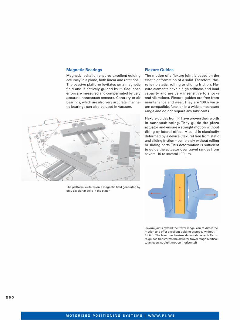
Flexure joints extend the travel range, can re-direct the motion and offer excellent guiding accuracy without friction. The lever mechanism shown above with flexu-re guides transforms the actuator travel range (vertical) to an even, straight motion (horizontal)
The platform levitates on a magnetic field generated by only six planar coils in the stator
Magnetic BearingsMagnetic levitation ensures excellent guiding accuracy in a plane, both linear and rotational: The passive platform levitates on a magnetic field and is actively guided by it. Sequence errors are measured and compensated by very accurate noncontact sensors. Contrary to air bear ings, which are also very accurate, magne-tic bearings can also be used in vacuum.
M O T O R I Z E D P O S I T I O N I N G S Y S T E M S | W W W. P I . W S
2 6 0
Use in Vacuum
Almost all stages can be modified for being used in different classes of vacuum. On re -quest, outgassing tests are carried out using a mass spectrometer.
Admissible temperature range of the motors Pressure range
Fine vacuum FV -20 to +150°C up to 1 × 10⁻³ hPa
High vacuum* HV -20 to +210°C 1 × 10⁻³ hPa to 1 × 10⁻⁷ hPa
Ultrahigh vacuum, no lubricants UHV -20 to +210°C 1 × 10⁻⁷ hPa to 1 × 10⁻⁹ hPa
Ultrahigh vacuum, vacuum lubricant UHV-G -20 to +210°C 1 × 10⁻⁷ hPa to 1 × 10⁻⁹ hPa
Ultrahigh vacuum, cryogenic range UHV-C -269 to +40°C up to 1 × 10-11 hPa
Extremely high vacuum XHV -20 to +300°C 1 × 10⁻⁹ hPa to 1 × 10-11 hPa
1 hPa = 1 mbar
Design and manufacture for ranges beyond these limits are offered on request.
* A high-vacuum class up to 1 × 10⁻⁶ hPa is also usual.
Vacuum Classification at PI
Decisive: Material SelectionTo determine the required vacuum class, it is necessary to know the application well. Crys-tallography or optical coating, for example, have different requirements not only with regard to the pressure range but also with regard to allowed residual elements in the vacuum chamber. Frequently, the partial pres-sure of carbon hydrides is decisive. They are part of lubricants and plastics, are released when pumping out the vacuum chamber and can contaminate surfaces. Laser applications in the UV range are particularly sensitive because carbon hydrides are split up and precipitate on the optical system.
For use in HV and UHV, special vacuum lubri-cants are used. On request, the lubricant may be defined when placing the order. The use of plastics and adhesives is reduced as far as possible.
Preferred Materials
■ Stainless steel
■ Aluminum
■ Titanium
■ Brass
■ FPM, e.g. Viton
■ Ceramics
■ Sapphire
■ PTFE, e.g. Teflon
■ PEEK
■ Polyimide, e.g. Kapton
■ Glass ceramics, e.g. Macor
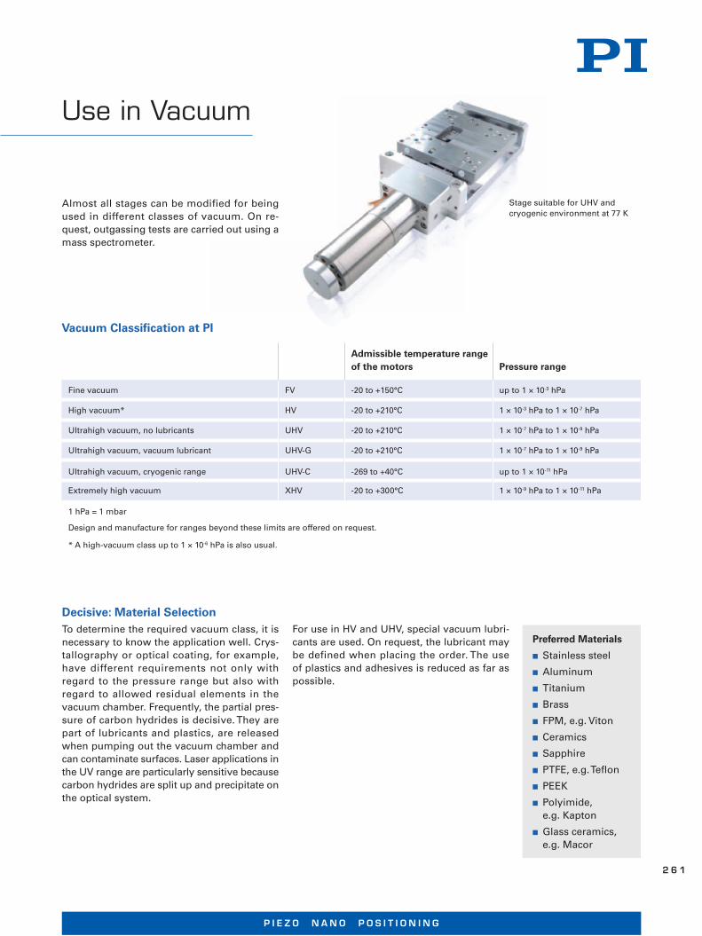
Stage suitable for UHV and cryogenic environment at 77 K
P I E Z O N A N O P O S I T I O N I N G
2 6 1

Mounting in CleanroomsVacuum stages are mounted under cleanroom conditions. All components are cleaned in ultrasound. They are dispatched in an antistatic and particle-free packaging.
Important Factors for Vacuum Stages
■ Low velocity: Maximum 10 revolu-tions per second
■ Short operating time
■ Vacuum stages should only be operated in vacuum
If not agreed otherwise, the following applies:
■ Bakeout temperature max. 80°C
■ Connectors mounted to the stage when being delivered are not inten-ded for use under vacuum condi-tions. Customers have to replace these test connectors by vacuum connectors
■ The vacuum feedthroughs are normal ly not included in the scope of delivery and may be ordered sepa rately, if required
Controllers, Amplifiers and Other Electronic DevicesIn general, the control electronics is not suit able for being operated in the vacuum chamber. It has to be mounted outside of the chamber.
FV to 10-3 hPa HV from 10-3 to 10-7 hPa UHV from 10-7 to 10-9 hPa
Motor - (just as air) vacuum motor suitable vacuum motor
Encoder - (just as air) modifi ed modifi ed
Cables - (just as air) 1 m PTFE (Tefl on) cable 1 m PI (Kapton) cable
Limit switches - (just as air) - (just as air)nonespecial UHV limit switches, on request
Surface anodized (just as air) not anodized* not anodized
Screws stainless steel stainless steelstainless steel with silver coating, gas emission bore
Lubrication (guidings, drive train)
vacuum lubricant vacuum lubricantUHV: no lubricant UHV-G: vacuum lubricant
Connector - (just as air)test connector, not suitable for vacuum
test connector, not suitable for vacuum
Holes - (just as air) only through-holes only through-holes
Other materials - (just as air) no CuZn alloysno CuZn alloys, no plastic
Bakeout temperature up to 50°C up to 80°Cup to 120°C, on request up to 150°C
*For use at up to 10-6 hPa vacuum stages with black anodized aluminum surface are offered.
M O T O R I Z E D P O S I T I O N I N G S Y S T E M S | W W W. P I . W S
2 6 2

SMC Controller Technology
The control technology of the SMC stepper motor controllers guarantees a particularly smooth running of the motors. The result is a very high position resolution, smooth feed and a large dynamical range of velocity and acce-leration. The efficiency of the SMC controllers is very high so that heating of the motors is avoided.
SMC controllers are based on a 32-bit proces-sor combined with high-resolution amplifiers making possible a position resolution down to nanometers. Driving high-precision mecha-nical systems, uniform feed velocities of less than 1 μm/s can be achieved.
Instead of a linear acceleration profile, you may choose a sin2 profile so that smooth, jerk-free accel eration and deceleration phases are possible.
If a stable long-term positioning is required, SMC stepper motor controllers also evaluate position feedback systems for closed-loop con-trol. Processing of an analog 1 V-peak-to-peak value allows you to set the position very accu-rately and continuously without limitation by a bit-depending digital transformation.
SMC controllers are available in different ver - s ions, from a one-channel compact unit to multi-axis control in 19 inch-case.
Precision Positioning with the SMC ControllerFigure 1 shows 100 nm steps of a PLS-85 lin-ear stage with 2-phase stepper motor without additional position feedback. The stage carries out these steps very accurately.
When commanding 25 nm steps (see fig. 2), there are more variations in the individual steps. On average, these deviations are ±5 nm only.
Fig. 1 PLS-85 with 2-phase stepper motor, without position control, 100 nm steps
Fig. 2 PLS-85 with 2-phase stepper motor, without position control, 25 nm steps
P I E Z O N A N O P O S I T I O N I N G
2 6 3
Position ControlThe positioning behavior for small steps can be further improved by using position feed-back control, in parti cular, if the analog output signal of a high-resolution sensor is used for processing.
SMC controllers can process sensor resoluti-ons down to 2 nm so that the posi tion reso-lution only depends on the sensor. However, environmental effects may not be neglected: Variations of ambient temperature by only 0.01°C already cause an expansion of the stage body by approx. 10 nm. If required, ultra-preci-sion stages or specific developments, such as stages with granite base with high-resolution linear encod ers, are used.
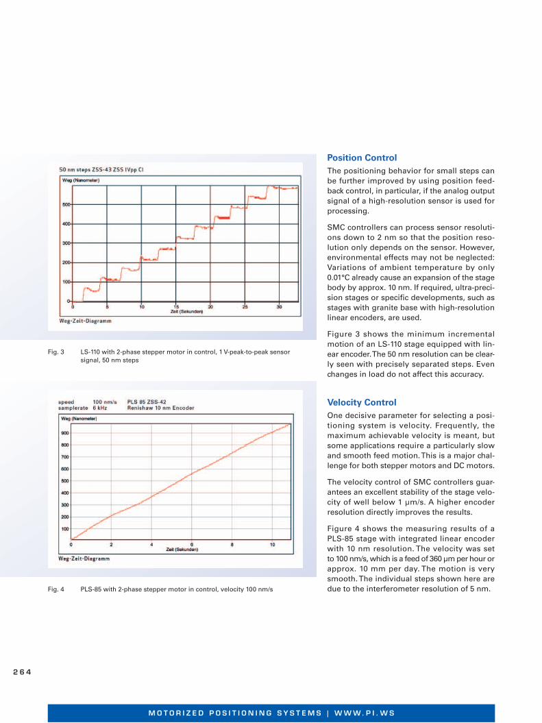
Figure 3 shows the minimum incremental motion of an LS-110 stage equipped with lin-ear encoder. The 50 nm resolution can be clear-ly seen with precisely separated steps. Even changes in load do not affect this accuracy.
Velocity ControlOne decisive parameter for selecting a posi-tion ing system is velocity. Frequently, the maximum achievable velocity is meant, but some applications require a particularly slow and smooth feed motion. This is a major chal-lenge for both stepper motors and DC motors.
The velocity control of SMC controllers guar-an tees an excellent stability of the stage velo-city of well below 1 μm/s. A higher encoder resolution directly improves the results.
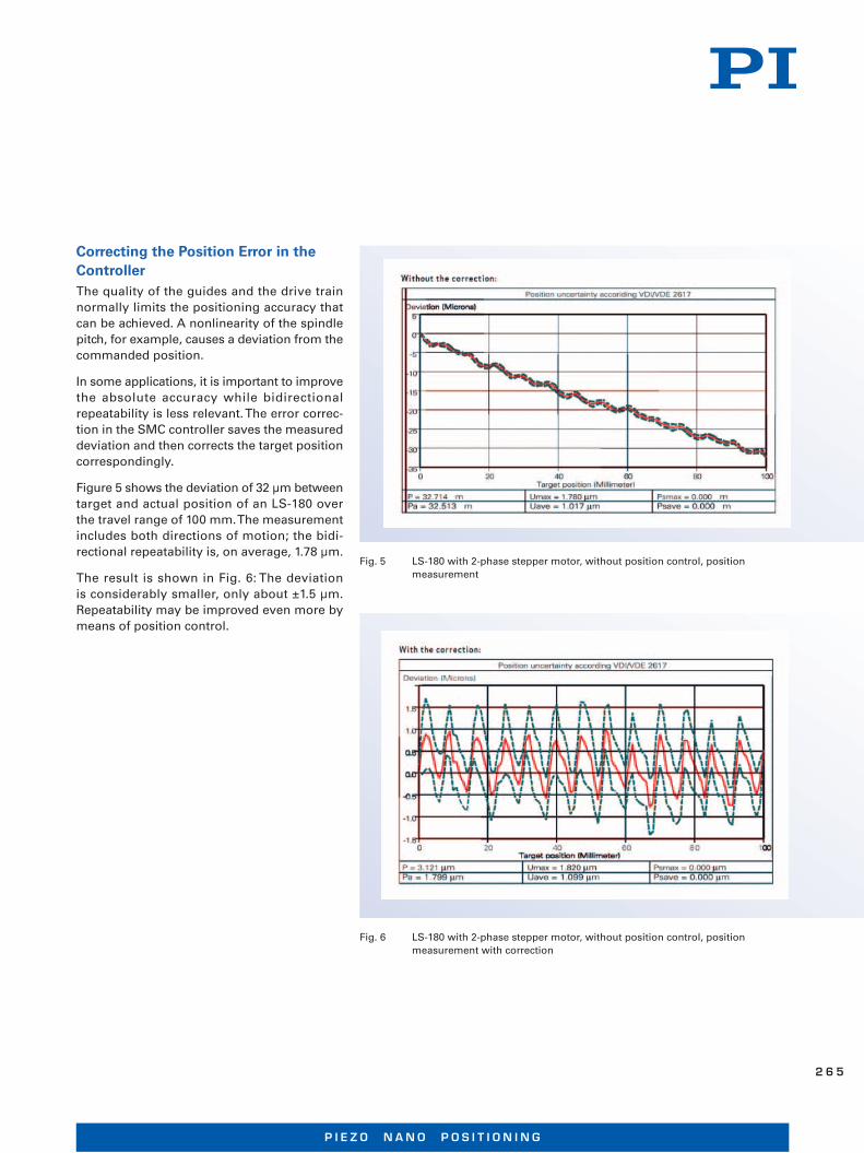
Figure 4 shows the measuring results of a PLS-85 stage with integrated linear encoder with 10 nm resolution. The velocity was set to 100 nm/s, which is a feed of 360 μm per hour or app rox. 10 mm per day. The motion is very smooth. The individual steps shown here are due to the interferometer resolution of 5 nm.
Fig. 3 LS-110 with 2-phase stepper motor in control, 1 V-peak-to-peak sensor signal, 50 nm steps
Fig. 4 PLS-85 with 2-phase stepper motor in control, velocity 100 nm/s
M O T O R I Z E D P O S I T I O N I N G S Y S T E M S | W W W. P I . W S
2 6 4
Correcting the Position Error in the ControllerThe quality of the guides and the drive train normally limits the positioning accuracy that can be achieved. A nonlinearity of the spindle pitch, for example, causes a deviation from the commanded position.
In some applications, it is important to im prove the absolute accuracy while bidirectional repeatability is less relevant. The error correc-tion in the SMC controller saves the measured deviation and then corrects the target position correspondingly.
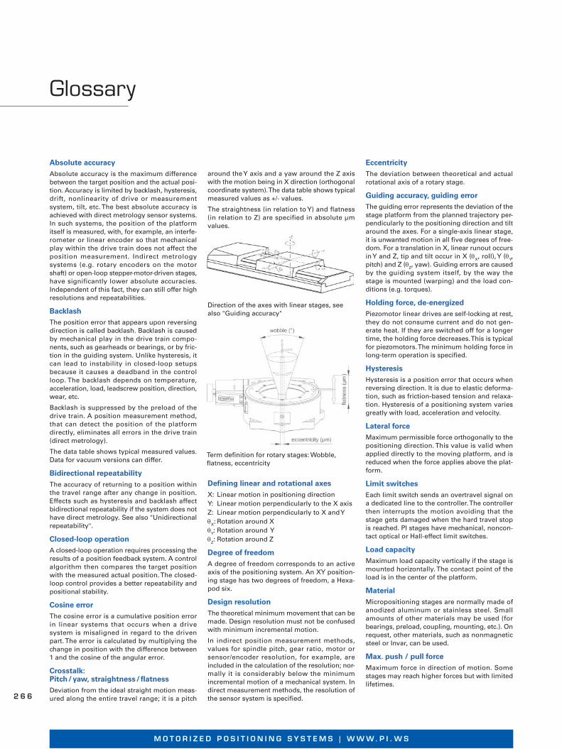
Figure 5 shows the deviation of 32 μm between target and actual position of an LS-180 over the travel range of 100 mm. The measurement includes both directions of motion; the bidi-rectional repeatability is, on average, 1.78 μm.
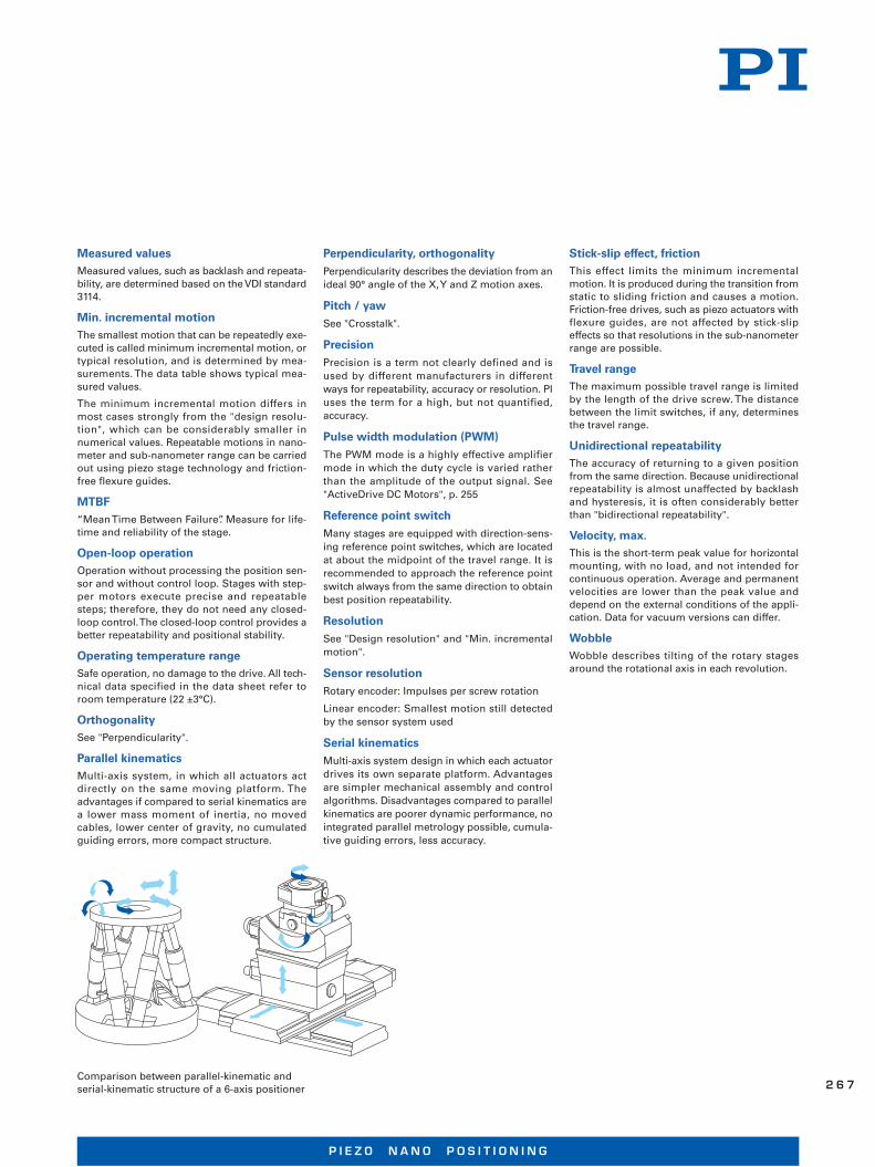
The result is shown in Fig. 6: The deviation is considerably smaller, only about ±1.5 μm. Repeatability may be improved even more by means of position control.
Fig. 5 LS-180 with 2-phase stepper motor, without position control, position measurement
Fig. 6 LS-180 with 2-phase stepper motor, without position control, position measurement with correction
P I E Z O N A N O P O S I T I O N I N G
2 6 5
Glossary
Absolute accuracyAbsolute accuracy is the maximum difference between the target position and the actual posi-tion. Accuracy is limited by backlash, hysteresis, drift, nonlinearity of drive or measurement system, tilt, etc. The best absolute accuracy is achieved with direct metrology sensor systems. In such systems, the position of the platform itself is measured, with, for example, an interfe-rometer or linear encoder so that mechanical play within the drive train does not affect the position measurement. Indirect metrology systems (e.g. rotary encoders on the motor shaft) or open-loop stepper-motor-driven stages, have significantly lower absolute accuracies. Independent of this fact, they can still offer high resolutions and repeatabilities.
BacklashThe position error that appears upon reversing direction is called backlash. Backlash is caused by mechanical play in the drive train compo-nents, such as gearheads or bearings, or by fric-tion in the guiding system. Unlike hysteresis, it can lead to instability in closed-loop setups because it causes a deadband in the control loop. The backlash depends on temperature, acceleration, load, leadscrew position, direction, wear, etc.
Backlash is suppressed by the preload of the drive train. A position measurement method, that can detect the position of the platform directly, eliminates all errors in the drive train (direct metrology).
The data table shows typical measured values. Data for vacuum versions can differ.
Bidirectional repeatabilityThe accuracy of returning to a position within the travel range after any change in position. Effects such as hysteresis and backlash affect bidirectional repeatability if the system does not have direct metrology. See also "Unidirectional repeatability".
Closed-loop operationA closed-loop operation requires processing the results of a position feedback system. A control algorithm then compares the target position with the measured actual position. The closed-loop control provides a better repeatability and positional stability.
Cosine errorThe cosine error is a cumulative position error in linear systems that occurs when a drive system is misaligned in regard to the driven part. The error is calculated by multiplying the change in position with the difference between 1 and the cosine of the angular error.
Crosstalk: Pitch / yaw, straightness / flatnessDeviation from the ideal straight motion meas-ured along the entire travel range; it is a pitch
around the Y axis and a yaw around the Z axis with the motion being in X direction (orthogonal coordinate system). The data table shows typical measured values as +/- values.
The straightness (in relation to Y) and flatness (in relation to Z) are specified in absolute μm values.
Defining linear and rotational axesX: Linear motion in positioning direction
Y: Linear motion perpendicularly to the X axis
Z: Linear motion perpendicularly to X and Y
θX: Rotation around X
θY: Rotation around Y
θZ: Rotation around Z
Degree of freedomA degree of freedom corresponds to an active axis of the positioning system. An XY position-ing stage has two degrees of freedom, a Hexa-pod six.
Design resolutionThe theoretical minimum movement that can be made. Design resolution must not be confused with minimum incremental motion.
In indirect position measurement methods, values for spindle pitch, gear ratio, motor or sensor/encoder resolution, for example, are included in the calculation of the resolution; nor-mally it is considerably below the minimum incremental motion of a mechanical system. In direct measurement methods, the resolution of the sensor system is specified.
EccentricityThe deviation between theoretical and actual rotational axis of a rotary stage.
Guiding accuracy, guiding errorThe guiding error represents the deviation of the stage platform from the planned trajectory per-pendicularly to the positioning direction and tilt around the axes. For a single-axis linear stage, it is unwanted motion in all five degrees of free-dom. For a translation in X, linear runout occurs in Y and Z, tip and tilt occur in X (θ
X, roll), Y (θ
Y,
pitch) and Z (θZ, yaw). Guiding errors are caused
by the guiding system itself, by the way the stage is mounted (warping) and the load con-ditions (e.g. torques).
Holding force, de-energizedPiezomotor linear drives are self-locking at rest, they do not consume current and do not gen-erate heat. If they are switched off for a longer time, the holding force decreases. This is typical for piezomotors. The minimum holding force in long-term operation is specified.
HysteresisHysteresis is a position error that occurs when reversing direction. It is due to elastic deforma-tion, such as friction-based tension and relaxa-tion. Hysteresis of a positioning system varies greatly with load, acceleration and velocity.
Lateral forceMaximum permissible force orthogonally to the positioning direction. This value is valid when applied directly to the moving platform, and is reduced when the force applies above the plat-form.
Limit switchesEach limit switch sends an overtravel signal on a dedicated line to the controller. The controller then interrupts the motion avoiding that the stage gets dam aged when the hard travel stop is reached. PI stages have mechanical, noncon-tact optical or Hall-effect limit switches.
Load capacityMaximum load capacity vertically if the stage is mounted horizontally. The contact point of the load is in the center of the platform.
MaterialMicropositioning stages are normally made of anodized aluminum or stainless steel. Small amounts of other materials may be used (for bearings, preload, coupling, mounting, etc.). On request, other materials, such as nonmagnetic steel or Invar, can be used.
Max. push / pull forceMaximum force in direction of motion. Some stages may reach higher forces but with limited lifetimes.
Direction of the axes with linear stages, see also "Guiding accuracy"
Term definition for rotary stages: Wobble, flatness, eccentricity
M O T O R I Z E D P O S I T I O N I N G S Y S T E M S | W W W. P I . W S
2 6 6
Comparison between parallel-kinematic and serial-kinematic structure of a 6-axis positioner
Measured valuesMeasured values, such as backlash and repeata-bility, are determined based on the VDI standard 3114.
Min. incremental motionThe smallest motion that can be repeatedly exe-cuted is called minimum incremental motion, or typical resolution, and is determined by mea- s urements. The data table shows typical mea -s ured values.
The minimum incremental motion differs in most cases strongly from the "design resolu-tion", which can be considerably smaller in numerical values. Repeatable motions in nano-meter and sub-nanometer range can be carried out using piezo stage technology and friction-free flexure guides.
MTBF“Mean Time Between Failure”. Measure for life-time and reliability of the stage.
Open-loop operationOperation without processing the position sen-sor and without control loop. Stages with step-per motors execute precise and repeatable steps; therefore, they do not need any closed-loop control. The closed-loop control provides a better repeatability and positional stability.
Operating temperature rangeSafe operation, no damage to the drive. All tech-nical data specified in the data sheet refer to room temperature (22 ±3°C).
OrthogonalitySee "Perpendicularity".
Parallel kinematicsMulti-axis system, in which all actuators act directly on the same moving platform. The advantages if compared to serial kinematics are a lower mass moment of inertia, no moved ca bles, lower center of gravity, no cumulated guiding errors, more compact structure.
Perpendicularity, orthogonalityPerpendicularity describes the deviation from an ideal 90° angle of the X, Y and Z motion axes.
Pitch / yawSee "Crosstalk".
PrecisionPrecision is a term not clearly defined and is used by different manufacturers in different ways for repeatability, accuracy or resolution. PI uses the term for a high, but not quantified, accuracy.
Pulse width modulation (PWM)The PWM mode is a highly effective amplifier mode in which the duty cycle is varied rather than the amplitude of the output signal. See "ActiveDrive DC Motors", p. 255
Reference point switchMany stages are equipped with direction-sens-ing reference point switches, which are located at about the midpoint of the travel range. It is recommended to approach the reference point switch always from the same direction to obtain best position repeatability.
ResolutionSee "Design resolution" and "Min. incremental motion".
Sensor resolutionRotary encoder: Impulses per screw rotation
Linear encoder: Smallest motion still detected by the sensor system used
Serial kinematicsMulti-axis system design in which each actuator drives its own separate platform. Advantages are simpler mechanical assembly and control algorithms. Disadvantages compared to parallel kinematics are poorer dynamic performance, no integrated parallel metrology possible, cumula-tive guiding errors, less accuracy.
Stick-slip effect, frictionThis effect limits the minimum incremental motion. It is produced during the transition from static to sliding friction and causes a motion. Friction-free drives, such as piezo actuators with flexure guides, are not affected by stick-slip effects so that resolutions in the sub-nanometer range are possible.
Travel rangeThe maximum possible travel range is limited by the length of the drive screw. The distance between the limit switches, if any, determines the travel range.
Unidirectional repeatabilityThe accuracy of returning to a given position from the same direction. Because unidirectional repeatability is almost unaffected by backlash and hysteresis, it is often considerably better than "bidirectional repeatability".
Velocity, max.This is the short-term peak value for horizontal mounting, with no load, and not intended for continuous operation. Average and permanent velocities are lower than the peak value and depend on the external conditions of the appli-cation. Data for vacuum versions can differ.
WobbleWobble describes tilting of the rotary stages around the rotational axis in each revolution.
P I E Z O N A N O P O S I T I O N I N G
2 6 7
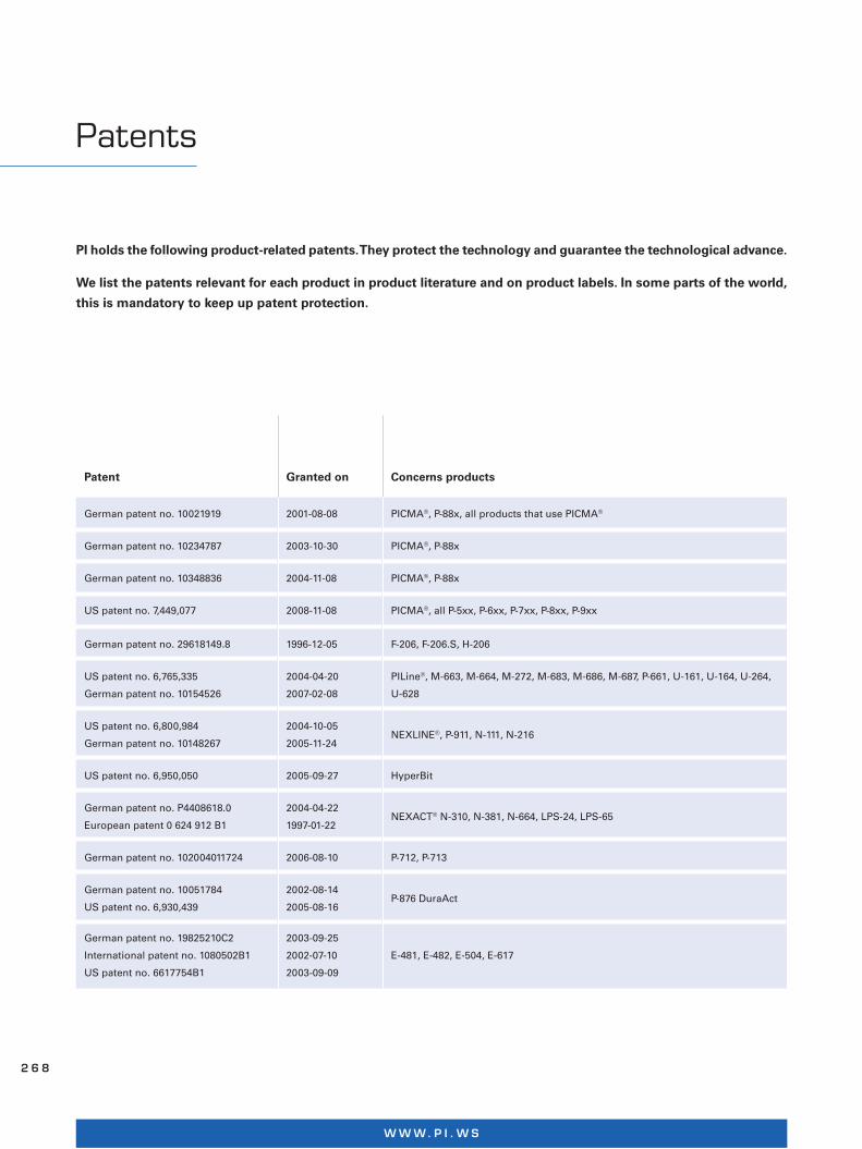
PI holds the following product-related patents. They protect the technology and guarantee the technological advance.
We list the patents relevant for each product in product literature and on product labels. In some parts of the world,
this is mandatory to keep up patent protection.
Patents
Patent Granted on Concerns products
German patent no. 10021919 2001-08-08 PICMA®, P-88x, all products that use PICMA®
German patent no. 10234787 2003-10-30 PICMA®, P-88x
German patent no. 10348836 2004-11-08 PICMA®, P-88x
US patent no. 7,449,077 2008-11-08 PICMA®, all P-5xx, P-6xx, P-7xx, P-8xx, P-9xx
German patent no. 29618149.8 1996-12-05 F-206, F-206.S, H-206
US patent no. 6,765,335
German patent no. 10154526
2004-04-20
2007-02-08
PILine®, M-663, M-664, M-272, M-683, M-686, M-687, P-661, U-161, U-164, U-264,
U-628
US patent no. 6,800,984
German patent no. 10148267
2004-10-05
2005-11-24NEXLINE®, P-911, N-111, N-216
US patent no. 6,950,050 2005-09-27 HyperBit
German patent no. P4408618.0
European patent 0 624 912 B1
2004-04-22
1997-01-22NEXACT® N-310, N-381, N-664, LPS-24, LPS-65
German patent no. 102004011724 2006-08-10 P-712, P-713
German patent no. 10051784
US patent no. 6,930,439
2002-08-14
2005-08-16P-876 DuraAct
German patent no. 19825210C2
International patent no. 1080502B1
US patent no. 6617754B1
2003-09-25
2002-07-10
2003-09-09
E-481, E-482, E-504, E-617
W W W. P I . W S
2 6 8

Technology Under Control
Customer and application-specific product developments are the basis for the success of the PI Group. Requirements have to be understood and a technological solution has to be found. Since the PI Group manufactures all key technologies in-house, technology and production can be adapted perfectly to fulfill the requirements. Evidence is provided by our products.
The Good Feeling When Your Expectations Are Met
Customers should know the performance of the system they use. Therefore, an informative measurement log is part of every supplied closed-loop nanopositioning system. All measure-ments are made with external, traceable measurement devices, such as high-resolution inter-ferometers.
Everything Under One Roof
The combined lift and swivel unit carries up to seven tons and permits 360° rotations. This allows us to qualify, for example, high-load Hexa-pods with load in the exact same orientation as in the customer‘s application
1 4
W W W. P I . W S
Technology of Parallel-Kinematic Precision Positioning Systems
Six Axes of Motion with Hexapods and SpaceFAB
Compact Positioning System – Advantages over Serial Kinematics Design – Components – Work Space
Page 181
Hexapods in Automation
Precise Trajectory Control Using G-Code – User-Defined Coordinate Systems – Standardized Automation Interfaces
Page 184
Motion Control Software from PI
Universal Command Set – PIMikroMove Host Software for Fast Start-Up – Fast Integration of PI Controllers in Third-Party Programming Languages and Software Environments
Page 186
Hexapod-Specific Software
Determining the Work Space – Checking the Permissible Load – PIVeriMove: Preventing Collisions withRestricted Work Space – Emulation: The Hexapod System as a Virtual Machine – HexaApp: PI Hexapod Control via iPhone, iPad or iPod
Page 189
H E X A P O D A N D S P A C E F A B | W W W. P I . W S
1 8 0
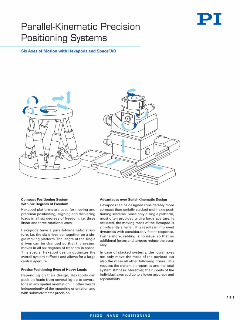
Compact Positioning System with Six Degrees of Freedom
Hexapod platforms are used for moving and precision positioning, aligning and displacing loads in all six degrees of freedom, i.e. three linear and three rotational axes.
Hexapods have a parallel-kinematic struc-ture, i.e. the six drives act together on a sin-gle moving platform. The length of the single drives can be changed so that the system moves in all six degrees of freedom in space. This special Hexapod design optimizes the overall system stiffness and allows for a large central aperture.
Precise Positioning Even of Heavy Loads
Depending on their design, Hexapods can position loads from several kg up to several tons in any spatial orientation, in other words independently of the mounting orientation and with submicrometer precision.
Parallel-Kinematic Precision Positioning SystemsSix Axes of Motion with Hexapods and SpaceFAB
Advantages over Serial-Kinematic Design
Hexapods can be designed considerably more compact than serially stacked multi-axis posi-tioning systems. Since only a single platform, most often provided with a large aperture, is actuated, the moving mass of the Hexapod is significantly smaller. This results in improved dynamics with considerably faster response. Furthermore, cabling is no issue, so that no additional forces and torques reduce the accu-racy.
In case of stacked systems, the lower axes not only move the mass of the payload but also the mass all other following drives. This reduces the dynamic properties and the total system stiffness. Moreover, the runouts of the individual axes add up to a lower accuracy and repeatability.
P I E Z O N A N O P O S I T I O N I N G
1 8 1
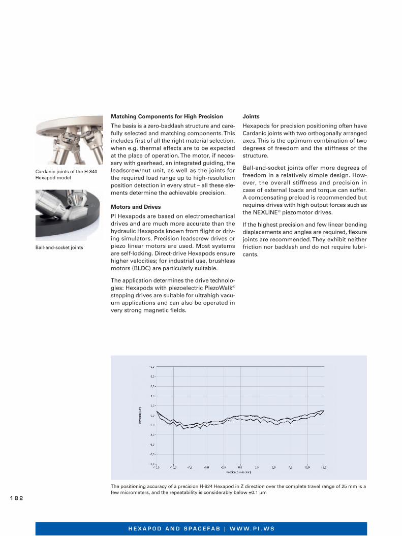
Matching Components for High Precision
The basis is a zero-backlash structure and care-fully selected and matching components. This includes first of all the right material selection, when e.g. thermal effects are to be expected at the place of operation. The motor, if neces-sary with gearhead, an integrated guiding, the leadscrew/nut unit, as well as the joints for the required load range up to high-resolution position detection in every strut – all these ele-ments determine the achievable precision.
Motors and Drives
PI Hexapods are based on electromechanical drives and are much more accurate than the hydraulic Hexapods known from flight or driv-ing simulators. Precision leadscrew drives or piezo linear motors are used. Most systems are self-locking. Direct-drive Hexapods ensure higher velocities; for industrial use, brushless motors (BLDC) are particularly suitable.
The application determines the drive technolo-gies: Hexapods with piezoelectric PiezoWalk® stepping drives are suitable for ultrahigh vacu-um applications and can also be operated in very strong magnetic fields.
Joints
Hexapods for precision positioning often have Cardanic joints with two orthogonally arranged axes. This is the optimum combination of two degrees of freedom and the stiffness of the structure.
Ball-and-socket joints offer more degrees of freedom in a relatively simple design. How-ever, the overall stiffness and precision in case of external loads and torque can suffer. A compensating preload is recommended but requires drives with high output forces such as the NEXLINE® piezomotor drives.
If the highest precision and few linear bending displacements and angles are required, flexure joints are recommended. They exhibit neither friction nor backlash and do not require lubri-cants.
Cardanic joints of the H-840 Hexapod model
Ball-and-socket joints
The positioning accuracy of a precision H-824 Hexapod in Z direction over the complete travel range of 25 mm is a few micrometers, and the repeatability is considerably below ±0.1 μm
H E X A P O D A N D S P A C E F A B | W W W. P I . W S
1 8 2
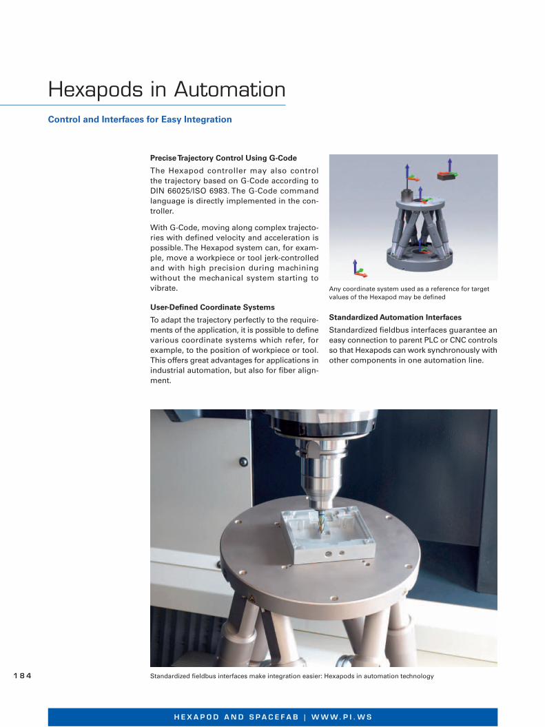
In this 3-strut design, additional degrees of freedom are produced because a passive strut can be moved in two or more axes. Example: In SpaceFAB, the individual struts are driven by one XY translation stage each
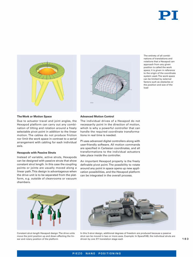
The Work or Motion Space
Due to actuator travel and joint angles, the Hexapod platform can carry out any combi-nation of tilting and rotation around a freely selectable pivot point in addition to the lin ear motion. The cables do not produce friction nor limit the work space in contrast to a serial arrangement with cabling for each individual axis.
Hexapods with Passive Struts
Instead of variable, active struts, Hexapods can be designed with passive struts that show constant strut length. In this case the coupling points or joints are usually moved along a linear path. This design is advantageous when the drive unit is to be separated from the plat-form, e.g. outside of cleanrooms or vacuum chambers.
Advanced Motion Control
The individual drives of a Hexapod do not necessarily point in the direction of motion, which is why a powerful controller that can handle the required coordinate transforma-tions in real time is needed.
PI uses advanced digital controllers along with user-friendly software. All motion commands are specified in Cartesian coordinates, and all transformations to the individual actuators take place inside the controller.
An important Hexapod property is the freely definable pivot point. The possibility to rotate around any point in space opens up new appli-cation possibilities, and the Hexapod platform can be integrated in the overall process.
The entirety of all combi-nations of translations and rotations that a Hexapod can approach from any given position is called the work space; it is given in reference to the origin of the coordinate system used. The work space can be limited by external factors such as obstacles or the position and size of the load
Constant strut-length Hexapod design. The drive units move the joint position up and down affecting the lin-ear and rotary position of the platform
P I E Z O N A N O P O S I T I O N I N G
1 8 3
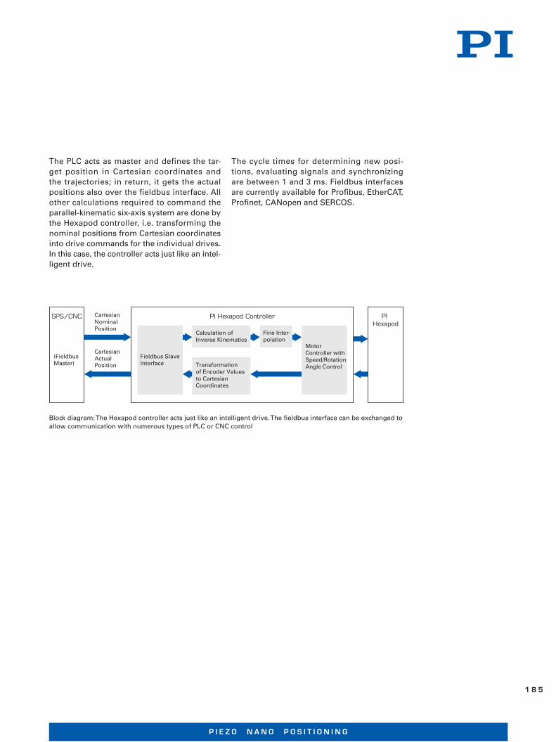
Precise Trajectory Control Using G-Code
The Hexapod controller may also control the trajectory based on G-Code according to DIN 66025/ISO 6983. The G-Code command language is directly implemented in the con-troller.
With G-Code, moving along complex trajecto-ries with defined velocity and acceleration is possible. The Hexapod system can, for exam-ple, move a workpiece or tool jerk-controlled and with high precision during machining with out the mechanical system starting to vibrate.
User-Defined Coordinate Systems
To adapt the trajectory perfectly to the require-ments of the application, it is possible to de fine various coordinate systems which refer, for example, to the position of workpiece or tool. This offers great advantages for applications in industrial automation, but also for fiber align-ment.
Standardized fieldbus interfaces make integration easier: Hexapods in automation technology
Any coordinate system used as a reference for target values of the Hexapod may be defined
Standardized Automation Interfaces
Standardized fieldbus interfaces guarantee an easy connection to parent PLC or CNC controls so that Hexapods can work synchronously with other components in one automation line.
Hexapods in AutomationControl and Interfaces for Easy Integration
H E X A P O D A N D S P A C E F A B | W W W. P I . W S
1 8 4
PI Hexapod Controller
Fieldbus Slave Interface
Motor Controller with Speed/Rotation Angle Control
Fine Inter-polation
Calculation of Inverse Kinematics
Transformation of Encoder Values to Cartesian Coordinates
Cartesian Nominal Position
SPS/CNC
(Fieldbus Master)
Cartesian Actual Position
PI Hexapod
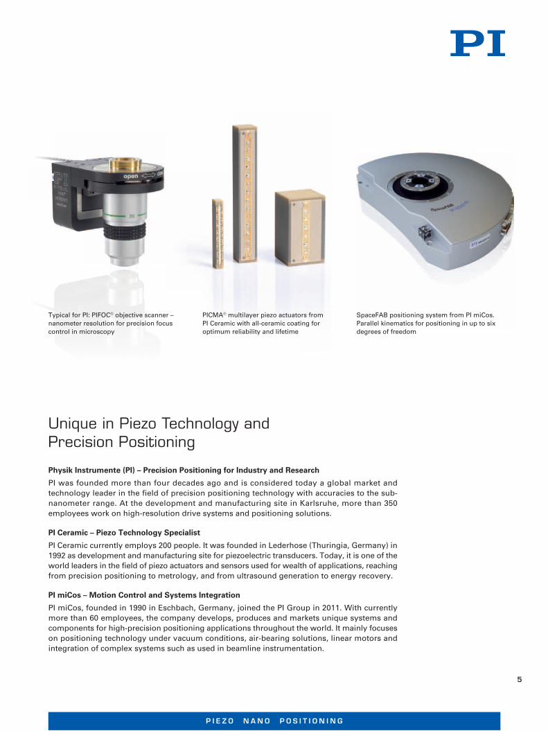
Block diagram: The Hexapod controller acts just like an intelligent drive. The fieldbus interface can be exchanged to allow communication with numerous types of PLC or CNC control
The PLC acts as master and defines the tar-get position in Cartesian coordinates and the trajectories; in return, it gets the actual positions also over the fieldbus interface. All other calculations required to command the parallel-kinematic six-axis system are done by the Hexapod controller, i.e. transforming the nominal posi tions from Cartesian coordinates into drive commands for the individual drives. In this case, the controller acts just like an intel-ligent drive.
The cycle times for determining new posi-tions, evaluating signals and synchronizing are between 1 and 3 ms. Fieldbus interfaces are currently available for Profibus, EtherCAT, Profinet, CANopen and SERCOS.
P I E Z O N A N O P O S I T I O N I N G
1 8 5

No other company in the world offers a broader and deeper portfolio of precision motion technologies than the PI Group. Continuous growth through the development of novel products and technologies is one of the main characteristics of the PI Group.
With more than 700 highly qualified employees all over the world, research and manufacturing centers on three continents and subsidiaries in 13 countries, the PI Group is in a position to fulfill almost any requirement with regard to innovative precision motion technology.
PI Group
4
W W W. P I . W S
Unique in Piezo Technology and Precision Positioning
Physik Instrumente (PI) – Precision Positioning for Industry and Research
PI was founded more than four decades ago and is considered today a global market and technol ogy leader in the field of precision positioning technology with accuracies to the sub-nanometer range. At the development and manufacturing site in Karlsruhe, more than 350 employees work on high-resolution drive systems and positioning solutions.
PI Ceramic – Piezo Technology Specialist
PI Ceramic currently employs 200 people. It was founded in Lederhose (Thuringia, Germany) in 1992 as development and manufacturing site for piezoelectric transducers. Today, it is one of the world leaders in the field of piezo actuators and sensors used for wealth of applications, reaching from precision positioning to metrology, and from ultrasound generation to energy recovery.
PI miCos – Motion Control and Systems Integration
PI miCos, founded in 1990 in Eschbach, Germany, joined the PI Group in 2011. With currently more than 60 employees, the company develops, produces and markets unique systems and components for high-precision positioning applications throughout the world. It mainly focuses on positioning technology under vacuum conditions, air-bearing solutions, linear motors and integration of complex systems such as used in beamline instrumentation.
Typical for PI: PIFOC® objective scanner – nanometer resolution for precision focus control in microscopy
SpaceFAB positioning system from PI miCos. Parallel kinematics for positioning in up to six degrees of freedom
PICMA® multilayer piezo actuators from PI Ceramic with all-ceramic coating for optimum reliability and lifetime
P I E Z O N A N O P O S I T I O N I N G
5
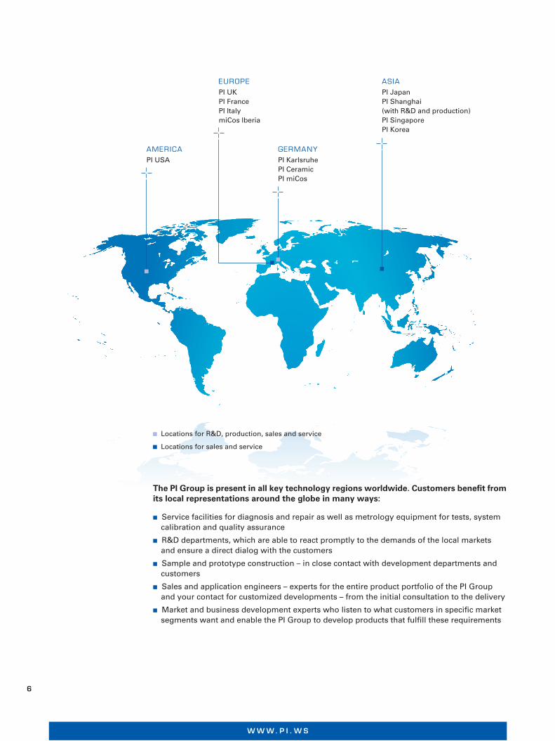
Locations for R&D, production, sales and service
Locations for sales and service
EUROPEPI UKPI FrancePI ItalymiCos Iberia
GERMANYPI KarlsruhePI CeramicPI miCos
ASIAPI JapanPI Shanghai (with R&D and production)PI SingaporePI Korea
AMERICAPI USA
The PI Group is present in all key technology regions worldwide. Customers benefi t from its local representations around the globe in many ways:
■ Service facilities for diagnosis and repair as well as metrology equipment for tests, systemcalibration and quality assurance
■ R&D departments, which are able to react promptly to the demands of the local marketsand ensure a direct dialog with the customers
■ Sample and prototype construction – in close contact with development departments and customers
■ Sales and application engineers – experts for the entire product portfolio of the PI Group and your contact for customized developments – from the initial consultation to the delivery
■ Market and business development experts who listen to what customers in specific market segments want and enable the PI Group to develop products that fulfill these requirements
6
W W W. P I . W S
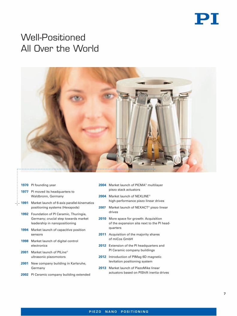
1970 PI founding year
1977 PI moved its headquarters to
Waldbronn, Germany
1991 Market launch of 6-axis parallel-kinematics
positioning systems (Hexapods)
1992 Foundation of PI Ceramic, Thuringia,
Germany; crucial step towards market
leadership in nanopositioning
1994 Market launch of capacitive position
sensors
1998 Market launch of digital control
electronics
2001 Market launch of PILine®
ultrasonic piezomotors
2001 New company building in Karlsruhe,
Germany
2002 PI Ceramic company building extended
2004 Market launch of PICMA® multilayer
piezo stack actuators
2004 Market launch of NEXLINE®
high-performance piezo linear drives
2007 Market launch of NEXACT® piezo linear
drives
2010 More space for growth: Acquisition
of the expansion site next to the PI head-
quarters
2011 Acquisition of the majority shares
of miCos GmbH
2012 Extension of the PI headquarters and
PI Ceramic company buildings
2012 Introduction of PIMag 6D magnetic
levitation positioning system
2013 Market launch of PiezoMike linear
actuators based on PIShift inertia drives
Well-Positioned All Over the World
P I E Z O N A N O P O S I T I O N I N G
7

PI is a synonym for top performance in precision motion technologies. We wish to in-spire
you with our products and we believe that we have exactly what it takes. PI offers a technol-
ogical spectrum that is beyond competition worldwide. Piezo actuator technology, voice-coil
drives, magnetic levitation technology, nanometrology sensors and digital controllers – we
can implement all of these technologies for any high-precision motion task. Piezo ceramics
are such an elementary part of our portfolio that we founded an entire company to produce
the highest quality piezo materials in the world: PI Ceramic. This way, we are independent
from general purpose components available on the market and can offer all key technol -
o gies from one source. This is what makes PI different and unique. And we need to be
unique to satisfy your specifi c requirements in drive and positioning technology.
However, technology is not our only strength. Even more important are all the people
working for and with PI. Permanent improvement of the workfl ow, fl at hierarchies, direct
communication, both internally and with our customers, are a very good basis. Our em-
ployees are looking forward to working for you. We wish to delight you with our solutions.
Yours sincerely,
Dr. Karl Spanner, President of PI
Dear customers,
The ”Wall of Fame“: Far more than 100 pa tents and patent pending technologies in the fields of nanopositioning, positioning controllers and piezoelectric drive systems
Integrated management system: Quality control, environmental protection and pro-tection of health and safety at work, certi-fied to ISO 9001, ISO 14001, OHSAS 18001
”PI is a strongly expanding, privately owned com-pany. PI stands for quality in products, processes and service. The development and manufacture is completely under the control and responsibility of PI. Profitability is required for financial independ-ence and a prerequisite for reinvestments in new technologies. It guarantees stability and a reliable partnership with our customers.
We, at PI, want to be our customers‘ partners and look for long-term customer relationships. Condi-tions to achieve this goal are fair prices and a mutu-al support when it comes to solving problems.“
The ”Wall of Fame“: Far more than 100 pa tents and patent pending technologies ith fi ld f iti i iti i
From the Mission Statement of Physik Instrumente (PI) GmbH
W W W. P I . W S
8

The PI Group can respond precisely to the customers‘ needs:
Specifi c requirements can often only be fulfi lled by custom-
ized solutions – solutions that can only be found by means
of unconventional and creative thinking.
Unconventional Ways
Small, smaller, smallest: Customer-specific drive solu -tions manufactured by the PI Group include a 30 mm wide positioner with electro-magnetic gear motor, a piezomotor-driven camera focus unit for mobile devices and piezo chip actuators manufactured in large quantities at low cost
eeds:
oom-
eeans
Precision steering mirror for an astronomical project re-quiring ultra-high stability and resolution. For this project, long-travel PI NEXLINE® linear drives were combined with absolute-measuring sensors
Unique Solutions, Broadest and Deepest Portfolio in Precision Motion Technologies
PI feels at home where unconventional solutions are of the essence in both industry and research. Today nanotechnology is also present in standardized industrial processes. With unconventional thinking and the broadest and deepest portfolio of precision motion technologies at hand, PI is in a position to offer solutions that far exceed the performance of general purpose systems. Understanding the customers‘ requirements is essential in finding a creative, sometimes surpris-ingly unconventional solution. The technological range available to PI always permits different approaches not limited to one single technology right from the start, an advantage that turns into a considerable competitive edge for the customer.
Why Scientists Rely on PI: Creativity for Research and Development
Thousands of scientific publications cite PI products because our systems help researchers achieve outstanding results faster. Custom developments for research customers are a daily business for PI. The spectrum reaches from modifications of standard products to special designs for extreme ambient conditions. Important fields of research are, for example, beamline instru-mentation, micro systems and nanotechnology.
OEM Customers Benefit from Our Integrated Management System
Optimized processes allow PI to provide customized products in quantities up to several 100 000 units cost-efficiently with exact adherence to supply deadlines. The range of OEM products offered by the PI Group varies, from ”compact actuators“ and sensors to highly integrated parallel-kinematic positioning systems with custom digital controllers and software. Evaluation of pre-production run samples, test procedures, production processes and quality management are all included in the development process.
The complete control over the design and manufacturing process provides the customer with significant advantages, because PI can modify and customize its products in all areas: Mechanics, electronics, metrology systems and software. Such solutions often go beyond the state-of-the-art, providing customers the competitive edge that is necessary to be successful in the market.
Control of All System-Critical Processes and Design Steps
The PI Group controls the design and manufacturing steps of all critical components from the piezo material to the mechanical construction, from the nanometrology sensors to the digital control circuits and software. This approach not only yields superior system performance but also allows us to support our systems for many years in the future, a fact that is appreciated by customers in research and industry alike.
P I E Z O N A N O P O S I T I O N I N G
9
Small and Large-Scale Precision
What does nanolithography have in common with astronomy? As different as they seem to be, both require precision motion with accuracy down to nanometers. With its decades of engineer-ing and manufacturing experience in nanopositioning and drive systems, PI has been working with world-class leaders in industry and research in these particular fields and many others.
Semiconductor Technology
The semiconductor industry is a pioneer when it comes to commercializing nanotechnology. Modern computer chips already require structures which are only a few nanometers wide. PI‘s piezomotor and actuator systems help to precisely align wafers, imaging optics and mask. Semiconductor test and inspection systems equally rely on the performance characteristics of PI positioning systems.
PI Group and Its Markets
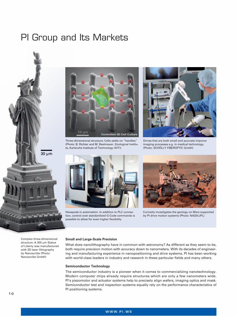
Complex three-dimensional structure: A 300 μm Statue of Liberty was manufactured with 3D laser lithography by Nanoscribe (Photo: Nanoscribe GmbH)
Drives that are both small and accurate improve imaging processes e.g. in medical technology. (Photo: SCHÖLLY FIBEROPTIC GmbH)
Three-dimensional structure: Cells settle on ”handles“ (Photo: B. Richter and M. Bastmeyer, Zoological Institu-te, Karlsruhe Institute of Technology (KIT))
Hexapods in automation. In addition to PLC connec-tion, control over standardized G-Code commands is possible to allow for even higher flexibility
Curiosity investigates the geology on Mars supported by PI drive motion systems (Photo: NASA/JPL)
Three-dimensional structu(Photo: B. Richter and M. Bte, Karlsruhe Institute of Te
Hexapods in automation. Ition, control over standardpossible to allow for even
W W W. P I . W S
1 0
Vacuum-Compatible, Non-Magnetic and Suitable for Low Temperatures
PI‘s piezoelectric drive systems can be modified to cope with extreme ambient conditions, such as ultrahigh vacuum, strong magnetic fields or extremely low temperatures. Piezoceramics are intrinsically compatible with these extreme conditions, but the selection of the right system components and the assembly process requires a lot of experience. PI miCos is an expert in classical drive technologies for UHV, in particular when it comes to designing complex multi-axis systems for high loads and long travel ranges.
Medical Technology
Piezo ceramics to generate ultrasonic waves, actuators for microdosing and the production of nanoliter drops as well as miniature piezomotors for mobile medication devices – all these are tasks for which the PI Group has been offering solutions for many years. For imaging processes, such as OCT, focusing or miniature zoom lenses, small and reliable drive systems are increasing-ly required. PI can offer products for all of these applications.
Biotechnology
Biotechnological applications using precise positioning system from PI are not only limited to typical optical procedures, such as focusing, or to moving and manipulation of samples in micros copy or in genome sequencers. Also for nano dosing and microfluidics, PI drive systems are unbeatable. For example, they allow the dosing of smallest volumes, with both high speed and high precision, in procedures such as PipeJet, or the design of the finest structures by means of nanoimprint or 3D lithography.
Microscopy
Optical methods have been relying on PI positioning systems for years, e.g. for aligning optical systems or samples. Piezo actuators and motors are increasingly replacing conventional drive systems because they are more compact, more precise and faster. Other non-optical microscopic processes, such as SEM (scanning electron microscope) and AFM (atomic force microscope), use PI systems due to their high accuracy and dynamics.
Imaging Methods
Nowadays, numerous industries depend on faster and more precise imaging methods. In all markets, the required tasks are focusing, zoom, object alignment and higher resolution. This ranges from the inspection of surface structures on semiconductors or flat screens with white-light interferometry to optical microscopy, and from the digitalization of documents to image stabilization for aerial photography and astronomy. In all of these fields, the PI Group is present with its precise, highly stable and dynamic positioning systems.
Industrial Automation
PI positioning systems can communicate directly with a PLC through fieldbus interfaces. They can be integrated in virtually every automated production line. A synchronized clock with other automated components can easily be achieved. Hexapod parallel-kinematic positioners can also be used in automated manufacturing processes and for precision alignment.
Astronomy and Aerospace Research
Highest precision and dynamics are required in astronomy to follow the motion of stars or to compensate atmospheric interferences. Hexapods from PI align secondary mirrors of telescopes with a precision of 1 μm or better; piezo-driven active mirrors increase the optical resolution and align the elements of large segmented mirrors. Today the PI Group is even present on Mars with two of its systems: Piezo actuators separate rock samples, motorized drives focus a camera and laser spectrometer on the Mars rover Curiosity science lab.
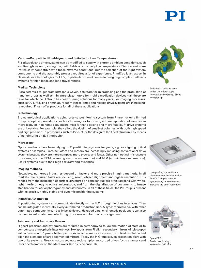
Endothelial cells as seen under the microscope (Photo: Lemke Group, EMBL Heidelberg)
SpaceFAB: 6-axis positioning system for 10-6 hPa
Low-profile, cost-efficient piezo scanner for biometrics: The CCD chip is moved dynamically in two axes to increase the pixel resolution
P I E Z O N A N O P O S I T I O N I N G
1 1
P I E Z O N A N O P O S I T I O N I N G
W W W. P I . W S
JAPAN
PI Japan Co., Ltd.Business Center Bldg. 5F2-38-5 Akebono-choTachikawa-shi, Tokyo 190-0012Tel. +81 (42) 526 7300Fax +81 (42) 526 [email protected]
PI Japan Co., Ltd.Hanahara Daini Bldg. #7034-11-27 NishinakajimaYodogawa-ku, Osaka-shiOsaka 532-0011Tel. +81 (6) 6304 5605Fax +81 (6) 6304 [email protected]
ITALY
Physik Instrumente (PI) S. r. l.Via G. Marconi, 2820091 Bresso (MI)Tel. +39 (02) 665 011 01Fax +39 (02) 610 396 [email protected]
CHINA
Physik Instrumente (PI Shanghai) Co., Ltd.Building No. 7-106Longdong Avenue 3000201203 Shanghai, ChinaTel. +86 (21) 518 792 98Fax +86 (21) 687 900 [email protected]
UK & IRELAND
PI (Physik Instrumente) Ltd.Trent House, University Way,Cranfield Technology Park,Cranfield, Bedford MK43 0ANTel. +44 (1234) 756 360Fax +44 (1234) 756 [email protected]
FRANCE
PI France S.A.S.244 bis, avenue Marx Dormoy92120 MontrougeTel. +33 (1) 55 22 60 00Fax +33 (1) 41 48 56 [email protected]
USA (East) & CANADA USA (West) & MEXIKO
PI (Physik Instrumente) L.P.16 Albert St.Auburn, MA 01501Tel. +1 (508) 832 3456Fax +1 (508) 832 [email protected]
PI (Physik Instrumente) L.P.5420 Trabuco Rd., Suite 100Irvine, CA 92620Tel. +1 (949) 679 9191Fax +1 (949) 679 [email protected]
SOUTH EAST ASIA
PI (Physik Instrumente) Singapore LLP20 Sin Ming Lane #05-60 Midview CitySingapore 573968 Tel. +65 665 98400Fax +65 665 [email protected] ID / MY / PH / SG / TH
KOREA
PI Korea Ltd.6F Jeongu Bldg.Cheonho-Daero 1111Gangdong-gu138-814 SeoulTel. +82 (2) 475-0060Fax +82 (2) [email protected]
GERMANY
PI miCos GmbHFreiburger Str. 3079427 EschbachTel. +49 (7634) 5057-0Fax +49 (7634) [email protected]
PI Ceramic GmbHLindenstr.07589 LederhoseTel. +49 (36604) 882-0Fax +49 (36604) [email protected]
Physik Instrumente (PI)GmbH & Co. KGAuf der Roemerstr. 176228 KarlsruheGermanyTel. +49 (721) 4846-0Fax +49 (721) [email protected]