Embed Size (px)
Citation preview

""MANFRED HEGGER""HANS DREXLER
""MARTIN ZEUMER
BASICS
MATERIALS
BIRKHAUSER-PUBLISHERS FOR ARCHITECTURE BASEL·BOSTON·BERLIN

CONTENTS
\\Foreword ~7
\\Introduction ~8
\\Principles for the choice of materials ~11
\\Perception of materials ~12
\\Material requirements ~17
\\Technical properties ~24
\\Classification of materials ~27
\\Typologies of building materials _27
\\Wood _33
\\Timber-based products ~36
\\Natural stone _39
\\Concrete _42
\\Mineral-bonded masonry units _45
\\Boards with mineral binders _48
\\Plaster and screeds~51
\\Ceramics and bricks _54
\\Metals _57
\\Glass ~62
\\Plastics ~66
\\Textiles and membranes 69
\\Designing with materials ~73
\\General conditions ~73
\\Basing design on material_75
\\Materializing the design ~76
\\Design approaches _78
\\In conclusion _85
\\Appendix ~86
\\Literature 86
\\Picture credits 87

FOREWORD
The materials out of which a building is made play a crucial part in
its effect and impact. They are important not just as the basis for construc
tion, but also as a mediator between building and people. Materials have a
story to tell about the building, its structure and its function. Surfaces are
perceived by the senses, and convey feelings. Materials can open a building
up to the outside world, can seem light and transparent, and the building
can also appear monolithic and solid - the choice of material is part of
design, in order to make the desired impression in terms of architectural
language. So the material qualities of a building must be chosen and used
with care. They should support the design, and where applicable even help
to shape it. The possibilities offered by different materials are many and
varied, making them an ideal design resource for architects.
The "Basics" series works through the important principles of a new
field of activity stage by stage, and provides a sound and useful instrument
for studying architecture. It does not set out to be a comprehensive collec
tion of specialist knowledge, but to give students readily comprehensible
explanations and foster their understanding of the important issues and
parameters in the various subject areas.
The "Materials" volume chooses to address the substantive properties
of materials and building components first and foremost. The authors do
not therefore provide a comprehensive survey, but concentrate on essential
subject matter for design and the way the building is later perceived. The
focus is on the insightful use of different materials and the wide range of
design possibilities they offer. First, their key properties are identified, so
that readers can find their way around the physical and emotional world
of material. The book systematically introduces the most important build~
ing material types and characterizes their individual properties. Typical
design approaches and principles in handing the material quality of build
ings are also explained.
With the aid of the "Materials" volume, students will be able to ac
quire knowledge about using different materials, so that they can make
their designs and ideas lively and e~ressive.
Bert Bielefeld
Editor
7

8
INTRODUCTION
Architecture lends material form to a design idea. Translating this
idea into built reality and the effect it makes on viewers is essentially
determined by the choice of material. An enormous variety of materials is
available, but a good design is inevitably restricted to very specific material qualities.
But what does material quality mean? As is common in current archi
tectural discussion, this is a borrowed term, liberally used, but ambiguous
and imprecise. The term "material quality" is often applied to the surface
of architecture. Materials contribute to the spatial experience by their ap
pearance, how they feel when touched, their smell, and their acoustic characteristics.
By referring to visible material quality, we attempt to get round the
reservation that the surface represents only part of material quality as a
whole. But perception involves more human senses than just sight, which
suggests that material quality must be more than the structure of a surface.
This point is clarified by a philosophical definition that coined the
term material quality. It suggests that a body consists of matter- of a ma
terial substance- but also conveys a sense of physical presence. So mate
rial quality arises from the material, and in this definition, many aspects
of materials fuse into a unity.
However, this explanation does not include all the topics included in
the concept of material quality. As well as the surface, the internal struc
ture and the resultant emergence of a physical entity, there is also an as
sociative plane, which is particularly significant in architecture. Materials
can be associated with and symbolize states of affairs. The fact that stone
stands for wealth and power can be grasped in any banking quarter. Thus,
there are three levels of meaning: visible, inner, and associative material quality.
Perceiving material quality is based on a personaL individual po
sition, which is neither right nor wrong. Many distinguished architects
have developed their own points of view, which they place in the context
of material quality: Alvar Aalto, Tadao Ando, Louis Kahn, to name only a
few, have used their choice of materials to put a lasting stamp on their architecture.
Effortless handling of materials and delight taken in experimenting
with them enrich architecture. The attraction of the new plays a key part.
Every architect is familiar with this. Many use choice of material as an
innovative device to make their buildings unique. That choice offers pos
sibilities that are increasingly becoming central themes in architecture.
Variety of material, and its alienation, exploring the limits of what is tech
nically possible, deliberately misusing materials or transferring material
from use areas unrelated to architecture are some of the stylistic devices
used by today's architects.
Choosing material requires knowledge of a large number of hard
facts. But it also needs intuition and a feeling for the suitable material in
a particular architectural context. This book will first examine material
quality in terms of objectively verifiable, "hard" factors. Important ques
tions include: what external conditions are materials exposed to, and how
do these affect them? How can the choice of material be systematized?
Once this basis has been established, "soft" factors become central. The
book will thus guide readers from the range of possibilities offered by
materials via design strategies to possible positions that develop from ma
terial quality.
In the chapter "Principles for the choice of materials" the reader will
be introduced to the basic issues relating to handling materials. It points
out the central influences affecting the course of material life cycles, and
provides the means for sensible evaluation. The chapter "Classification of
materials" explains criteria for choice, capacities and fields of application
for selected building materials. Specifications are given for possible per
formance based on the properties of materials, and brought together as a
material use catalogue. Finally, the chapter "Designing with materials" dis
cusses different ways of designing out of and with materials. The various
design approaches or principles are described and explained to give the
reader ideas and indicate the field of possibilities for handling materials,
or how a design problem can be approached from this perspective.
9

~
~
1 ~
1
>@
10
I material I I
perceived as II requirements II technical properties
visual
tactile
thermal
acoustic
olfactory
I I I
I sui tobi l i ty
II ecolog i co 1
II econom1 c
I
build 1ng sc1ence ~ for use requirements requ 1 rements
I 1 sui table I ~ environmen- II investment! ~
I
mechen ica 1 ~ tally friendly cost weighted
I ~ non-tox1c I I chem~col ~
I ~ clean 1 ng and mo1ntenance
II run n ~ n g cost ~
onented we1ghted
I 1 durobi l i ty related II life cycle } cost optimlled
PRINCIPLES FOR THE CHOICE OF MATERIALS
For a long time, there was little choice of building materials. There
were few materials available, but they were universally known. Knowledge
about how to deal with them was developed and handed down over genera
tions. The onset of industrialization gradually broke down this historically
matured manageable quality. Today we have an immense number of mate
rials at our disposal. Specialists such as "material scouts" provide archi
tects with information about materials and innovations. The field of pos
sible performance has also grown with the number of materials available.
~ \\Hint:
The term '1material scout" is not a
precise description of a profession but is a possible area in which
an archi teet can work, researching
or developing new and innovative
materials, systematizing knowledge
about the use of building materials
for special purposes, and supporting designing architects by providing
creative ideas.
11

Surface perception
Transparency
Colour
12
Architects are not expected to be familiar with all these properties in de
tail, but they should be aware of connections and consequences. They will
combine all levels on which materials can be considered in a knowledge
of their properties, within a design and in the later execution stages. The
design process is driven by properties relating to perception, as well as
ecological, economic and technical properties, and those related to use.
> Fig.!
PERCEPTION OF MATERIALS
The effect made by materials is discerned by all the senses. The following come into play:
_Visual sense - sight
Tactile sense - touch
_Thermal sense - feeling
_ Auditory sense - hearing
_ Olfactory sense- smell
Visual For humans, about 90 percent of information stimuli are based on
the sense of sight. So it is hardly surprising that visual considerations are
usually the first basis for making decisions about building materials.
Sight is based on transmitted rays. The corresponding material prop
erty is the reflection of rays from the surface of the material. The light
striking a material therefore plays a key part in visual perception. The skin
of the building materials, from glossy to matte, from light to dark, from
homogeneous to textured, is the basis for architectural design. The neutral
smoothness of industrially manufactured surfaces can be just as fascinat
ing as sensitively controlled elements of roughness, which are sometimes
perceptible only at second glance. Three-dimensional structures acquire
greater depth if light strikes the texture at an acute angle. Careful placing
of windows or light sources can enhance the three-dimensional quality of
the materials. > Fig. 2
This effect can be so greatly reinforced by transparent materials
that it seems to work regardless of the material used. Semi-transparent,
evenly textured planes, such as glass or plastic, can be superimposed; per
forated opaque materials can also be used. The effect created - interfer
ence - changes the appearance of the building according to the angle from
which it is viewed. The building is enlivened, and large even surfaces can
acquire an enhanced sense of vivacity. > Fig 3
A building material's colour also has an important part to play.
If the material is light in colour, it makes a particularly strong three-
Scale
Rssociation
dimensional impact, as the eye registers the contrast - the difference in
brightness - before the colour quality. This contrast is particularly great
in light-coloured materials because of shadows cast. Dark materials offer
very little contrast, and so their surfaces lose their plastic quality, and
tend to look two-dimensional.
Colours influence the way space is perceived. Warm colours make a
space look smaller, while cold ones make it look bigger. Colours can also
affect users on a subconscious, emotional plane: cold colours are distanc
ing, but warm colours are stimulating.
The size and scale of building materials and surfaces also help to
determine the impression they make. Different textural dimensions influ
ence perception from close up, and in the middle and far distance. A ma
terial's effect is thus defined by the degree of prefabrication, element size,
texturing, jointing, and other surface treatments. In this way, the choice of
materials can match a particular building to its surroundings or make it
stand out from them. > Fig. 4
The almost endless variety of visual stimuli is reduced to those
that are important for viewers in the perception process, and made into a
personal image through their own knowledge. The architect can take ad
vantage of this by playing with familiar associations. For example, using
unusual small brick formats on a fa~,;ade can make a building seem par
ticularly generous, as a result of subconscious assumptions about scale.
> Fig.5
13

14
Tactile In tactile perception, the whole body becomes a sense organ, and
particularly the hands. They explore the contact areas of the materials
and their properties: even or rough, smooth or dull, hard or soft, cold or
warm. > Fig. 6
Handles and handrails offer a particular good bold if the hand can
grasp them completely. Soft materials yield to the hand, and can thus make
a handle seem particularly pleasant. Construction elements that seem
warm invite touch, and encourage people to use features like parapets and
window-seats. > Fig. 1
Surface temperatures, radiation and reflection in construction ele
ments influence thermal sensations via the skin. There is a pleasant and
apparently warm impression if the components that are touched draw lit
tle heat out of the body, as in materials with a low thermal mass and high
radiation. Heavy building materials, such as steel and concrete, draw heat
out of the body when touched and thus seem cold.
Thermal This principle also works without contact, as people register the
temperature difference between the air and adjacent surfaces. Lack of ra
diation is interpreted as cold. In contrast, solid surfaces exposed to the sun
can, later, at night, seem to be warm.
A total of four factors play a crucial part in human thermal percep
tion: the speed at which air is moving, air temperature, radiation from
) ~
Indoor climate
adjacent surfaces, and air humidity. These factors combine to create the
climate within a space. Humidity particularly affects thermal comfort. If
it rises, the perceived temperature rises as well. Materials with sorptive
properties can regulate humidity. Such materials, particularly plaster and
clay, but also other solid building materials, can contribute to a particu
larly pleasant indoor climate. > Fig. s
Materials with a low thermal mass can thus create a "shack climate",
which is strongly affected by temperatures brought into the building from
the outside - especially when it is extremely hot or cold. The reverse is the
"castle climate": heavy building materials with a high thermal mass help
to create a stable climate by reducing temperature amplitude, decoupling
the space from extreme exterior temperatures.
fi \\ Hint:
Sorption enables a building material to draw
moisture out of the air and store it on its
surface. Moisture is absorbed or released in
relation to humidity.
15

> ~
Contrast
Rgreement
16
Senses working together
With sight taking the lead, other sensory experiences help to con
cretize material qualities. Hearing and smell are important, as well as the
senses that have already been mentioned. For example, the muted crunch
made by the round grains of sand can be heard when walking along a sandy
path. The smell of wood is associated with wellbeing. The more senses a
material addresses, the sooner a satisfying overall experience can be cre
ated by a material or a space.
Designers have two possible ways of deliberately stimulating and
enhancing perception: one is to present the channels of perception with
contrasting experiences, for example through an unexpected tactile effect
contrasting with the visual one. The anticipated sensation is missing, and
this sense of disturbance becomes an experience. But it can also produce
a subconscious feeling of discomfort if inconsistencies of this kind go be
yond a certain level.
Conversely, materials can create a particularly all-embracing and
harmonious overall image. Agreements, harmony between the visual im
pression and the other levels of perception create physical wellbeing. The
individual impressions complement each other, and combine to form a sat
isfying overall image. Architecture then achieves its aim through a wide
range of perceptions open to simultaneous experience. But this image can
tip over as well, in the direction of emotional overload and ultimately ba
nality.
MATERIAL REQUIREMENTS
Every material must fulfil its function in terms of specific require
ments . Its use-related properties determine the utility value of a property
for its owners and users, so they address this purpose directly. The de
mands placed on materials can be broken down into four groups:
_Comfort requirements
· Protection from effects of the environment
_ Maintaining function
_ Low environmental pollution
Comfort requirements
Materials meet comfort requirements at the points where their sur
faces come into direct contact with the user. Such points include floor,
wall and ceiling surfaces in particular, or movable parts such as doors and
windows. Comfort can be expressed in technical values to only a limited
extent. Very few specifications for individual properties can be quantified,
> see chapter Technical properties such as the antistatic performance of elastic
floor coverings . In other areas designers are left to their own experience
and feelings.
Safe for health One fundamental demand made on any material is that it should not
>@ Comfortable temperature
~ \\ Hint:
be a risk to human health, and consequently hygiene. Harmful materials
are often suspected as such long before it can be proved.
Materials that are concealed within the structure often contribute
to a feeling of atmospheric and climatic comfort within a building. Heat
insulating materials prevent the building from losing energy, and ensure
that surface and air temperatures do not fall below a pleasant level. Ther
mal mass enables materials to match surface and air temperature, capture
moisture from the air and thus smooth out the temperature and humidity
within a space. Wind seals, draughtproof layers in wall superstructures,
reduce air movement that can cause discomfort, as do seals on moving ele
ments such as doors and windows.
~ \\ Hint:
Memory is also linked with sensory perception,
so st i mulating many senses makes memories more likely to last.
Substances posing on element of ri sk ore most often found in surface coatings , adhesi ves and binders, but also in elastic or textile coverings. Careful research is recommended.
17
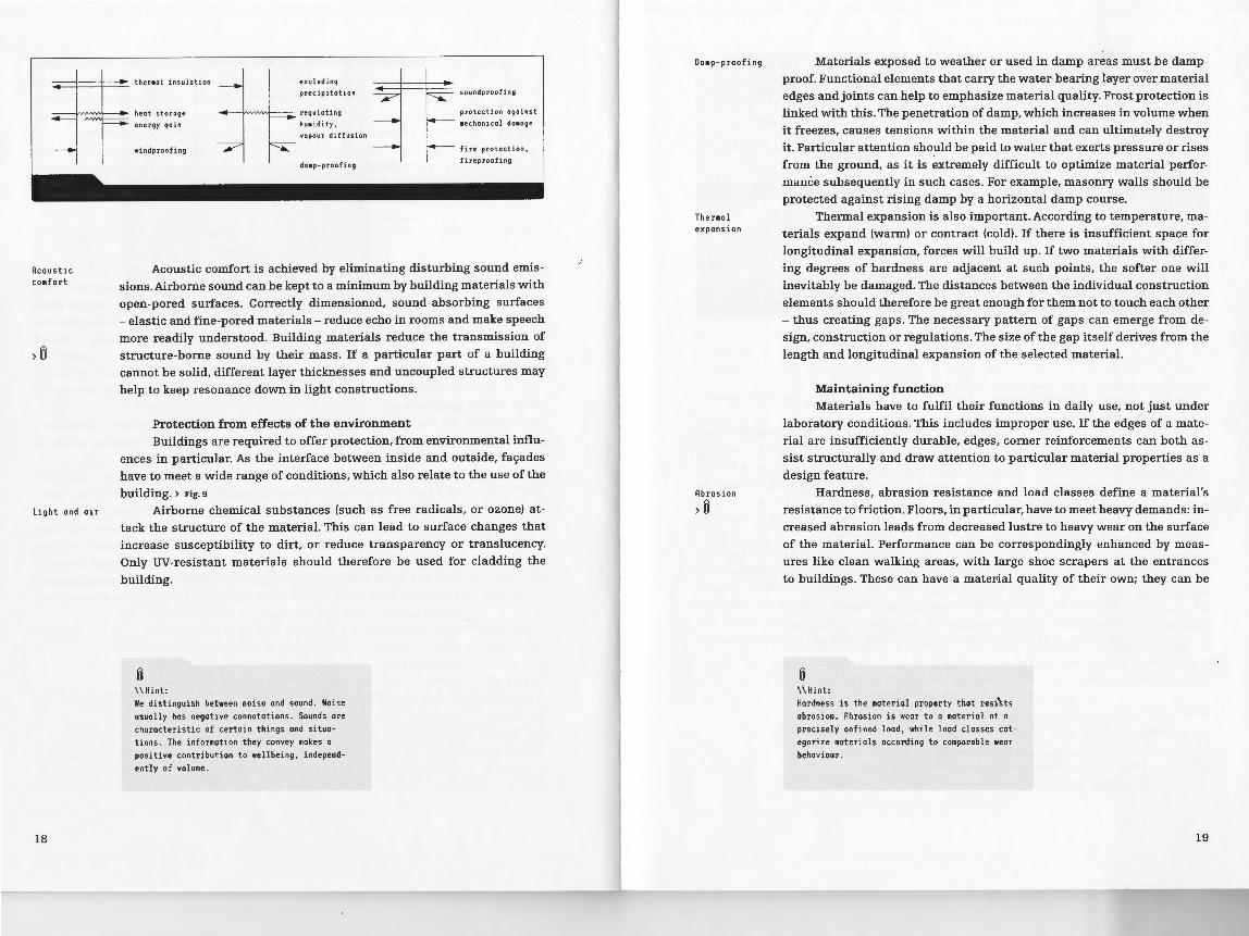
.-=:1----+-.._. thermal insulation excluding
precipitation soundproofing
Acoustic co mf ort
>@
Light and a i r
18
heat stor age
energy ga 1n
win dproofin g
~~regulating
humidity,
vapour diffu s ion
damp -p roofing
protection against
!~ mechanical dama ge
1.....-- fire protection,
fireproofin g
Acoustic comfort is achieved by eliminating disturbing sound emis
sions. Airborne sound can be kept to a minimum by building materials with
open-pored surfaces. Correctly dimensioned, sound-absorbing surfaces
-elastic and fine-pored materials- reduce echo in rooms and make speech
more readily understood. Building materials reduce the transmission of
structure-borne sound by their mass. If a particular part of a building
cannot be solid, different layer thicknesses and uncoupled structures may
help to keep resonance down in light constructions.
Protection from effects of the environment Buildings are required to offer protection, from environmental influ
ences in particular. As the interface between inside and outside, fagades
have to meet a wide range of conditions, which also relate to the use of the
building. ) Fig. s Airborne chemical substances (such as free radicals, or ozone) at
tack the structure of the material. This can lead to surface changes that
increase susceptibility to dirt, or reduce transparency or translucency.
Only UV-resistant materials should therefore be used for cladding the
building.
~ \\Hint: We distinguish between noise and sound. Noise usually has negative connotations. Sounds ore
characteristic of certain things and si tuations. The information they convey makes a positive contribution to wellbeing , independ
ently of volume.
Da mp-proofi ng
Ther mal expansio n
Abrasion
>@
Materials exposed to weather or used in damp areas must be damp
proof. Functional elements that carry the water-bearing layer over material
edges and joints can help to emphasize material quality. Frost protection is
linked with this. The penetration of damp, which increases in volume when
it freezes, causes tensions within the material and can ultimately destroy
it. Particular attention should be paid to water that exerts pressure or rises
from the ground, as it is extremely difficult to optimize material perfor
mance subsequently in such cases . For example, masonry walls should be
protected against rising damp by a horizontal damp course.
Thermal expansion is also important. According to temperature, ma
terials expand (warm) or contract (cold). If there is insufficient space for
longitudinal expansion, forces will build up. If two materials with differ
ing degrees of hardness are adjacent at such points, the softer one will
inevitably be damaged. The distances between the individual construction
elements should therefore be great enough for them not to touch each other
- thus creating gaps. The necessary pattern of gaps can emerge from de
sign, construction or regulations. The size of the gap itself derives from the
length and longitudinal expansion of the selected material.
Maintaining function Materials have to fulfil their functions in daily use, not just under
laboratory conditions. This includes improper use. If the edges of a mate
rial are insufficiently durable, edges, corner reinforcements can both as
sist structurally and draw attention to particular material properties as a
design feature.
Hardness, abrasion resistance and load classes define a material's
resistance to friction. Floors, in particular, have to meet heavy demands: in
creased abrasion leads from decreased lustre to heavy wear on the surface
of the material. Performance can be correspondingly enhanced by meas
ures like clean walking areas, with large shoe scrapers at the entrances
to buildings. These can have a mater-ial quality of their own; they can be
~ \\Hint:
Hardness is the material property that resi'sts
abrasion. Abrasion is wear to a material at a precisely defined load, while load classes cat
egorize materials according to comparable wear behaviour.
19

Maintenance needed
Durability
>0
20
made of metal, plastic or textiles, and may also match the floor covering
that follows.
The need for surfaces that need little care and maintenance should
be considered even at the design stage. Cleaning represents a particular
kind of demand in its own right, as it can also cause abrasion or lasting
damage to surfaces. Skirting boards protect walls from being damaged by
cleaning at the point where they meet the floor. Details of this kind, which
seem unimportant at first, are actually omnipresent, and help to make ar
chitecture more expressive in terms of its materials.
Materials should be able to perform for as long and as often as pos
sible. This attribute is defined technically as durability. If a building has a
finite useful life, as in exhibition centres, for example, the degree of dura
bility can be planned appropriately in advance. If it cannot, all materials
should be as durable as possible. Each material has its own useful life,
according to functional demands. It should therefore be possible to replace
~ \\Hint: Durability, or useful life, defines the period for which o building element con remain usable.
Ageing
any functional component without destroying another. This requirement
raises the subject of layered structures, in walls for example, which con
tain technical equipment, protective surfaces, insulating materials and
loadbearing structures.> Fig. 10
Ageing processes are evidence of transience and decay; expressed
positively, they illustrate temporal qualities and life. Just like people, build
ings and their materials can age with dignity. After a certain time, almost
any material shows traces of the wear and tear it has undergone, whether
from external influences or from use. This ageing can take the form of a
natural patina, which may be very attractive, and so can be caused delib
erately. An oxide layer creates a patina on metal, on weatherproof steel, for
example, or on bronze.
Ageing is clearly demonstrated by larch as a fagade cladding: the
material first turns grey from its original reddish hue as a response to
weathering, through the effects of UV radiation. The radiation breaks down
the natural colour pigments in the wood, although they survive longer in
protected areas. > Fig. 11 Materials considered particularly innovative at
first can decline in aesthetic appeal as they age rapidly, and the signs of
ageing show. They then quickly cease..looking up-to-date.
If ageing processes and traces of use are accepted, these also model
the material. Retaining such traces can tell a story of the distant past.
> Fig.12
Some materials, such as glass or polished stone, show no visible
signs of ageing. Time seems to pass them by without trace. > Fig. 13.
21

Entropy
>@ Material cycle
Life-cycle assessment
22
Environmental pollution
Building uses a very high proportion of resources and creates the
most waste. Decisions made during the planning process thus have consid
erable environmental consequences. Over the life cycle of a building, high
ecological impacts go hand in hand with additional expenditure. For this
reason too, it makes considerable sense to look more closely at environ
mental pollution when choosing materials.
For example, using aluminium consumes a great deal of energy and
water for the treatment of the bauxite. This means there is more heavy
metal in the water and ultimately the food cycle. This triggers a process of
substance flows known as entropy. The aim should always be to minimize
substance flows in order to keep entropy down.
The ideal way of using material is within a closed substance circle:
refuse can become a secondary raw material. The quality of recycling is
crucial to its ecological value, to retaining the parent substance and the
energy stored in the material. We distinguish between reuse (repeated
use of the material), alternate use (recovering basic chemicals from
refuse) and extended use (using treated refuse for new purposes). There
is also a distinction between downcycling (material loop with declining
material quality) and recycling (material loop with the same material quality).
Life cycle assessments are a comprehensive method of evaluating
building materials from the point of view of environmental technology.
Various harmful materials are weighted within impact categories so that
they can be allotted a characteristic value, with the unit identifying the
most important harmful substance. Key impact categories are primary
energy content, greenhouse effect and ozone depletion potential. > Tab. 1
~ \\Hint:
Entropy identifies the mixture of substance
and energy flows, effectively the increase
of disorder in the world. In o closed system
(such as the earth), it can never be reduced, but always thrusts towards a maximum.
Tob.l:
that: Independently of the choice of materials, it is generally the case
_reduction to structural essentials can be advantageous.
_durable, light structures are generally preferable to massive ones.
_the use of materials that retain C02 is a positive factor.
_invisible building components are particularly suitable for
problem-free optimization.
_the longer a building is intended to be used, the more important it
is to consider this phase of use.
_building components with short useful lives are more environmen
tally polluting because renewal costs accumulate more rapidly.
_in housing construction, the environmental impact made by build
ing materials is particularly significant, because they are generally
used in small pieces, and the level of finish is high.
The ecological criteria of a building material are increasingly becom
ing a factor. They do not hinder the planning process, but in fact enrich it,
and can generate additional creativity by asking new questions and posing
alternatives. For example, if materials are reused in prominent positions
> Fig. 10 they can be seen as evidence of a sustainable approach, and then
create an additional plane of significance for building materials.
Selected impact categories in o life cycle assessment
Characteristic val1es of a life cycle assess1ent in building Abbreviation Unit
Primary energy content (non-renewable) PEI MJ
Primary energy content (ren ewable) PEI MJ
Greenhouse potential GWP 100 kg C02 eq
Ozone depletion potential ODP kg CCL 3F eq
Acidification potential AP kg S0 2 eq
Eutrophication potential EP kg PO,'- eq
Photo-oxidant formation ("summer smog potential") POCP kg C2H, eq
23

Physical properties
Mechanical propert i es
>~ > ~
Chemical properties
Questions in choosing material
~ \\Hint:
TECHNICAL PROPERTIES
Technical properties are key criteria in material selection. A particu
lar material can be chosen only by considering its technical performance,
in other words on the basis of its "inner values", its physical. mechanical
and chemical parameters.
Basic physical specifications are available for all building materials:
gross density is a core value that enables other properties such as thermal
mass or thermal conductivity capacity to be deduced, thus giving an initial
overall technical impression of a material.
Mechanical properties place particular constraints on the potential
use of a material for construction. They include the material's strength and
rigidity, its response to forces acting on it through plastic or elastic distor
tion, and its surface hardness. Mechanical properties are linked in many
ways with thermodynamic properties and those relating to moisture, e.g.
the frost resistance of natural stone. One important mechanical character
istic of natural stone is its abrasion resistance, the extent to which it can
resist mechanical friction. This correlates with high density and high com
pressive strength, again the basis for a low water absorption coefficient.
This is a key feature for frost resistance, and is determined by a stone's
porosity and capillarity. A high value, as for sandstone, for example, means
that the stone has to be protected from water penetrating. The most impor
tant characteristics are summarized in Table 2. ) Tab. 2
The chemical behaviour of a building material can change through
direct contact with chemicals or environmental influences. They include
corrosion (especially of metals). leaching of salts (in mineral-bound mate
rials, ceramics), resistance to UV light (materials including plastics), and
reactions to other building materials (for adhesives, mastics etc.).
The key questions when selecting a material arise mainly from the
intended effect and the requirements profile:
~ \\Hint:
The Mohs hardness scale places materials in relation to each other by creating groups of
materials thot will scratch the next softer
one. The scale ranges from 1 (tole) to 10
(diamond).
The vapour diffusion resistance value identi
fies how much greater the resistance to water vapour is compared to an air layer of identical thickness.
24
~2: ~~-------------------------------------------------------l Important properties with units J
Properties Characteristic Syobol Unit
Physico 1 properties Gross density p kglm'
Thermal conductivity ), W/mK
Specific thermal copoci ty J /kgK
Thermal storage number
Mechanical properties Mohs scale hardness HM Wh/m2K
Compressive strength f , N/mm 2
Tensile strength ft N/mm 2
Modulus of elostici ty N/mm 2
Thermodynamic properties Thermal expansion coefficient a 1/K
Moisture-related Vapour diffusion resistance value
Water absorption coefficient w kglm'h'·'
Which human sense should be stimulated, and how will people per
ceive the material? What natural and use-related influences will the intended function
have on the material?
These questions can be answered in terms of specific material quali
ties, which can usually be reduced a few technical properties. Conversely,
the properties of a material can give rise to a wide variety of new and in
novative possible uses and applications, some of them surprising.
25

26
Typology based on material composition
Non-homogeneous building materials
Tob.3:
CLASSIFICATION OF MATERIALS
The properties of certain selected building materials are set out in
greater detail below. Once the key characteristics of a material have been
established for a particular purpose, it becomes possible to compare ma
terials with each other. The first step is to divide materials into groups
with similar property profiles. This considerably reduces the difficulty of
making comparisons, and sharpens the designer's eye for the performance
to be expected from a group of materials, or a specific material.
TYPOLOGIES OF BUILDING MATERIALS
If alternatives are being sought for materials, it makes sense to
structure the initially overwhelming variety of materials and characteris
tics according to type. Materials are distinguished by their composition,
structure and the way they are manufactured. This speeds up the selection
process and can promote the discovery of interesting alternatives.
Under material composition we first distinguish organic and inor
ganic materials. > Tab. 3
Mineral building materials are always first associated with solid
building components, and metal components with flat components or
those in the form of bars, because of their high performance.
However, these associations work only for homogeneous building
materials. If compound materials are used, individual components often
Building moteriols classified according to material composition
Selected 1aterials
Dependent properties
Inorganic 1aterials Mineral
Natural stone
Concrete
Gloss
Brick
- Density Average
- Strength Brittle, high compres-
sive strength, low
tensile strength
- Thermo! conductivity Average
- Combustibility Not combustible
Organic •ate:rials Metallic
Metals Wood
Bitumen
Plastics
High Low \
Tough , high compressive Tough, dependent on and tensile strength internal structure
High Low
Not combustible Largely combustible
27
•

>Q
Q \\Important:
Materials and their properties present a
properties profile. If these properties
are combined and used comprehensively in a structure, we can say they have been used justly.
cover different functions within a structural element. A concrete floor is a
good illustration here: although its surface suggests a homogeneous stone
material. the structural steel it contains absorbs tensile forces. Structural
sections consisting of various components are affected by a complex inter
play of the individual components' properties and quantities. For example,
the specific pH of the concrete prevents the steel from corroding. The steel
in turn prevents the concrete floor from sagging, thus avoiding the forma
tion of cracks. So it is only when the materials start to work together that
the just use of materials is fully in evidence, with every single material making the maximum contribution to the whole.
This philosophy for optimizing properties systematically is increasingly being practised. For example, glass has for some time not been a
single material but a whole group of materials with a wide range of avail
able properties, surface treatments and layering sequences, which opens
up endless possibilities of function and design. Remarkable and innova
tive architectural achievements are now usually based on the interplay between materials and familiar surfaces.
classification of building materials
A11orphous material Crystalline materials Fibrous materials
Selected materials Gloss Metals Wood Plastics Cloy
Bitumen Brick
Dependent properties
- Direction Non-directional Largely non-directional Directional Thermal conductivity Lower than for Higher than for Low
crystalline materials amorphous materials - Strength Tougher than crystalline More brittle than High tensile strength
materials amorphous materials in the grain direction
28
Typology based on structural composition
Typology based on production
Tob.S:
Another way of classifying materials is their structural composition.
Tab.4
The structure of fibrous elements such as wood can make a striking
contribution to the design. For example, they can form a loadbearing level,
or a complex loadbearing system by bending.? Fig. 14
Another way of classifying materials is based on how they are ob
tained or produced, the first subdivision being into natural and artificial
materials. On a second level. a distinction can be made between amor
phous, intermediate and shaped materials, and semi-finished products.
The way in which a material is obtained is also a factor: natural materials
are always produced by subtractive processes, while additive processes
and those concerned only with shaping can be applied to artificial materi
als. > Tab. 5
Materials classified according to production
Obtained by
Production
Process
Natural 11ate:rials
Extraction process
Raw material
Processed material
Subtractive
Artificial 11ate:riols
Production of parent substances
Rmorphous materials
Intermediate materials
Shaped materials
Subtractive
Additive
Shaping
29
•

30
Typology based on dimensions
Finally, building materials differ from each other in their dimensions. Filler materials have low dependency levels and need a structural
envelope. Small-format materials need to be combined if they are to form
an effective structural element. This is achieved by further processing
based on the dimensions of each material. Repetition and jointing create their own aesthetic. In contrast, large-format materials can be a
structural element, e.g. a shear wall. They have to take up aspects of
the building grid and the fagade design on the level of construction and function.
Classifying materials typologically can provide information about how they are used, the extent to which they can be worked, and their architectural potential. Thus, for natural materials, the existing dimen
sions can be the essential criterion for use, or the way they are obtained can deliberately be left showing in the resultant material. > Fig.I5
The more elaborately a natural material is processed, the more its natural appearance is lost. The effects of the manufacturing process and
subsequent work stand out more clearly, and the natural variations in the material shift into the background. The use of industrial production
in architecture can go so far as to explore the constantly changing technical boundaries of a process in a completely new way. > Fig. 16
In this way, every material and its performance characteristics contribute to the way space is designed. The diversity of materials and
ways in which they can be deployed opens up almost inexhaustible possibilities for giving architecture a quite specific material quality and
impact, appealing to all the human senses. Examples of these possibilities and potentials are assessed below for the most important build
ing materials, and also compared with each other in terms of material specifications.
Tab.6: Material specifications
Mata:riol
Wood
(see page 33)
Ti11ber products (see page 36)
Natu:ral stone (see page 39)
Conc:rete (see page 42)
Prefabricated 111ine:ral units (see page 45)
Mineral slabs (see page 48)
Screeds I :rende:ring (see page 51)
Properties Use
Natural directional building material, The directional structure is suit-
easy to work; high tensile and compressive able for loadbearing structures and
strength in groin direction; moisture
depe_ndent expansion; low weight and thermal conductivity; natural, strong,
rough texture in conifers and oak, fine
texture in maple, beech and birch.
Made of wood, and share its properties;
the directional structure is reorganized
loadbearing layers, which can also
provide thermal insulation; fa):ade
cladding through accumulations and
overlapping of boards ond shingles;
high-quality furniture ond handles.
Directional panels or beams are used for loadbearing structures or rein-
as required when producing panels; reason- forcement; non-directional timber
ably priced production from timber waste products are used for furniture,
built-in units, cladding and insula
tion.
Natural inorganic building material
with a stratified or homogenous struc
ture according to origin; high density,
hardness, compressive strength, thermal
conductivity and storage capacity, and
resistance to weathering; elaborate
extraction and processing, creating
special material effects.
Rs liquid stone, shares similar proper
ties with natural stone; properties can
be changed by additives; concrete loses
volume when worked and needs a secondary
loodbearing system.
Properties similar to natural stone;
gross density and thermal conductivity
are usually lower; shrinks little in
production, which means high dimensional
stability.
Have similar properties to prefabricated
mineral units; usually non-homoge-
neous structure (e.g. reinforcement or
packaging) as a material compound for
increased strength and lower weight.
According to binding agent, high strength,
seal tightness and surface hardness, or
low strength, damp inhibiting ond vapour
permeable; similar properties to prefabr~
cated mineral units; elasticity provided
by additives.
The compressive strength of stone is
exploited for loadbeoring masonry;
slabs ore sufficient for using most
of the properties; this produces
a surface design supported by a
substructure, as a fa~ade or floor
covering.
Pressure-loaded shell l~dbeoring
structures; can absorb tensile forces
only in combination with steel or
other materials: it is then suit
able for freely shaped construction
elements and loadbearing structures.
Masonry with a low proportion of
joints for a monolithic effect;
possible single-shell use in cases of
low thermal conductivity; can also be
used in sheet form for floor cover
ings.
Cladding for walls and upright struc
tures, cement-bound also as fa~ade
cladding; functional materials for
sound- and fireproofing.
Functional protective layers for
frost-, damp- ond fireproofing;
screeds as pressure-distributing
floor slobs; rendering as wall and
ceiling cladding with multiple
textures.
31

Materials
Cera•ics I bricks
(see page 54)
Metals
(see page 57)
Glass
(see page 62)
Plastics
(see page 66)
Textiles and
•e•b:ranes (see page 69)
32
Properties
Inorganic material with high strength,
hardness and ther11al conductivity, which
con be reduced by additives and shaping;
high capillarity of earthenware, low for
sintered wore; high production-related dimensional tolerances.
Shiny elastic material with high density
and resistance to compressive and tensile forces; high thermal and electrical
conductivity; corrosion, which forms a
durable protective coating on some metals;
wide variety of possible shapes.
Amorphous, brittle and transparent
material with a high gross density,
compressive strength and hardness; load
bearing capacity dependent on surface
tension; overage thermal conductivity,
reduced in combination with coatings.
Usually translucent, dense organic mote
rial with low thermal conductivity and
gross density; elasticity, high tensile
strength and temperature expansion; almost
ony property con be generated by compound or composition.
Soft materials with low thermo! conduc
tivity, suitable only for tensile loads;
two-dimensional structure, three-dimen
sional only with felting; waterproof with coating.
Use
Bricks ore used for masonry based
on the octametric system, also in
single-shell foro in cases of low
thermal conductivity; can be used in
sheet form for fo<;ode cladding ond floor coverings.
Statically optimized bars for load
bearing structures or concrete
reinforcement; thin sheets and panels
for cladding, especially for exterior
use; prefabricated ports, e.g. bear
ings, handles, pipework.
Transparent fa~ades and windows;
wide variety of surface finishes can
reduce light permeability or admit
light on one side only if o reflec
tive surface is applied.
Universally useful material, from
high-strength fibre-compound sections
via interior finish and fa~ade panels
to sealing strips or membranes; func
tional materials e.g. coatings or adhesives.
Sui table for weatherproofing as o
stretched material; home floor and
wall coverings, mobile room dividers,
coverings for seating and handles;
felt for acoustic separation of components.
>~
Structure and properties
Swelling and shrinking
~ \\Hint:
WOOD
Wood is almost universally available as a renewable building mate
rial. It can be used in a variety of ways and is reasonably priced. It is easy
to work, and has an individual smell according to species. Wooden surfaces
have natural colour and texture, and can become darker or lighter. Wood
draws little heat out of the human body when touched, and so is experi
enced as pleasant, sensual and warm.
Because of its cellular structure, wood has a fibrous or grainy struc
ture, is low in weight and high in strength. As the fibres lie longitudinally
within the trunk, it can absorb greater tensile, pressure and bending loads
in this direction than laterally to the grain. It is thus best to load wood
in the same way as the tree itself was loaded by weight and wind loads.
> Fig. 18 At the same time it has low thermal conductivity combined with
high heat storage capacity. Wood also has a high C02 storage capacity, and
is excellent in terms of return to the material cycle.
As well as expanding when the temperature rises, wood is also sub
ject to moisture-dependent swelling and shrinkage. Wood stores water in
its cells when humidity levels are high, and releases it again when humid
ity is low. This behaviour must be accommodated in planning and process
ing. Shrinkage cracks can occur when wood is dried, but they have little
effect on static loadbearing properties. > Fig. 18
Q \\Important:
Wood has an organic composition very similar
to plastic (see p. 66), o fibrous structure or
groin, which is exploited when making wooden
panels (seep. 36); it con be used very simi
larly to metal for construction purposes (see p. 57).
Many thes of wood ore porticulorly resistant
to pests because they contain resin and other
natural substances, and are thus very well
suited for outdoor use; these include the Cen
tral European timber species oak and larch.
33

cross-section
heartwood ',,
,_
sapwood
radial section '•,,
annual ring
early wood
---, late wood
"
Timber species
Timber protection
>\I
Solid wood for construction
34
The properties of wood vary considerably according to the species
of tree, but they also depend on growth factors, which show in branch
positioning and the annual rings in the wood. The fundamental classifi
cation is as coniferous or deciduous timber. Conifers, the older group in
terms of evolution history, have a simpler cell-type structure and share
very similar properties (e.g. gross density). Coniferous trees (spruce, pine,
fir) grow more quickly, usually have strongly marked annual rings, and
are less suitable for compressive and tensile loading. Deciduous timber is
more specialized in its cell structure, depending on the species. Native de
ciduous species (oak, beech, maple) are denser and stronger than conifer
ous timbers. Deciduous trees can produces heartwood of a different colour,
consisting of dead cells with deposited tanning agents. They offer a great
variety of textures and colours, linked with various technical properties
and possible uses.
Wood is very durable if used correctly. When used outdoors it is
vulnerable to weathering, pests and rot. The tanning agents in decidu
ous timber or resins in coniferous timber can provide natural protection.
Structural timber protection means restricting the environmental effects
in order to make the timber more durable. For fac;:ades this can be achieved
with projecting roofs, structural protection for the timber's particularly
absorbent outer surfaces, protection from splashing, and draining any
moisture that may appear by means of dripping from the edges. For chemi
cal timber protection, pest-inhibiting substances are painted onto the sur
face, impregnations forced into the fibres under pressure, or the timber
can be heat-treated.
The timber industry addresses the heterogeneity of this natural
building material by classifying the wood by quality. Gluing wood pro
duces laminated timber in which any growth damage to the individual
timber parts can be eliminated.
The long tradition of timber construction has led to a large number
of building methods and timber structures. If wood is used for loadbearing
structures, the dimensions of the timber products, mostly in strip, slat or
Boards and shingles
Veneers
plank form, suggest a skeleton construction method (e.g. truss and timber
frame methods). But flat and solid methods using planks or logs can also
be chosen; these also exploit the timber's good thermal insulation and heat
retention properties.> Fig. 19
Boards and shingles can be fitted together to form flat areas in scale
patterns, by overlapping or using tongue-and-groove details; outdoors as
roof or fac;:ade cladding. Timber shingles are fitted in several layers, and
are extremely durable. > Fig. 17 left 1 centre Boards or shingles can be used
rough-sawn, planed or sanded. Structures intended as non-slip surfaces
outdoors have a contoured timber surface. If parquet is used, textures or
even pictures can be created by laying the units in different directions.
Similarly to wooden louvres, these give different colour effects as light is
refracted at different angles according to its incidence, thus contributing
to the lively quality of a room. > Fig.l7 right
Timber makes a particular impact on people, and not just through
solid construction. Thin surface veneers applied to reasonably priced
wood-based products have a similar effect. This means that rare and high
quality wood can be used in a variety of ways; particular textures can be
achieved by the way it is cut. > Fig. 19 Sawn and sliced veneers produce a
particularly high-quality surface, highlighting the knots and grain. Peeled
veneers are available in an endless band of veneer, and can be used both
for making hardwearing timber-based products and as decoil'ative veneer.
But if the veneer is to be visible, only timber species with a low-key texture
such as birch, ash or maple are used, as otherwise unnatural grain patterns
can emerge.
35

I timber-based I
moter1als
r--- reducing to fibre sawing peeling planing chipping
I I cut tiober I I veneers I I wood wool II chips ] I fibre I
TIMBER-BASED PRODUCTS
> ~ Wood or wood scraps are cut up or reduced in size to make timber
based products, and reassembled with or without a binder to produce a
new material. > Fig. 21 > ~ The fibrous structure of the timber is reorganized. This makes it pos
sible to produce flat materials in stable shapes and with defined proper
ties that can be manufactured industrially and are easy to work. They can
either appear similar to natural wood, or create an alienating effect.
Timber-based products can be subdivided into veneer, chip and fibre
products. > Fig. 22
Production and properties
Here, the natural properties of the wood shift into the background,
although they are more or less retained visually according to the product
concerned. Their strength derives from the pressure used in manufacture,
and the strength of the timber component and the hardened binding agent.
The position of the timber components in relation to each other defines
the possible uses. The more directional the structure created is, the better
suited the product is for structural items with a loadbearing requirement.
The gross density increases in proportion to increasing strength (up to
1200 kg/m3). The smaller the wood elements are, the more non-directional
the overall structure becomes: a stratified sheet made up of flat veneer
36
~ \\Hint: Timber-based products are organic in composi
tion, fibrous in structure, and similar to min
eral-bonded panels in production and use (see
page 48).
~ \\Hint: Bonding agents are responsible for the vapour
emitted in timber-based product manufacture.
These agents may contain toxic substances
(see chapter Material requirements , Safe for health).
Surfaces
Lamination
Possible uses
layers has a structure running on two axes because the individual lay
ers are turned at right angles to each other, while a sheet of fibreboard is
non-directional except for the sheet plane. Good insulation properties can
be exploited as well as strength. The lowest gross density for fibreboard
sheets lies at about 50 kg/m3.
In contrast with wood, the surface and the internal structure of tim
ber-based products differ. Higher-quality surface layers are chosen for ve
neered products, and these help to produce an even and more solid visual
effect, and for chipboard products smaller chip material is.used for the
surface, which is more highly compressed in order to create an even sur
face for lamination. These differences in surface and internal structure can
be seen at the cut ends of the timber-based products.
Timber-based products also serve as reasonably prices support ma
terials for high-quality veneers or other surfaces, especially on a plastic
base. The borders between valuable natural wood veneers and imitations
of natural wood (e.g. laminated floors) are becoming increasingly fluid.
Like wood itself, timber-based products swell and shrink according to
their moisture content, i.e. "move", so lamination on one side would pro
duce tensions within the material, and later cause damage to the product
or the surface. The appropriate surface is thus never applied to one side
of the product only, but always to both sides. Every tension that arises is
balanced by a counter-tension.
Timber-based products are used in fields ranging from structural
engineering via cladding to built-in units and designer objects, and can be
used indoors and out. When used in fa~:ades, structural timber protection
acquires particular significance for the durability of the material in terms
of weatherproofing, for example, or as a drip edge.
Structural uses The great strength of the material is a key factor for structural use.
Here, considerable creative potential is offered by its statical load rating
associated with formability in relation to forces acting on it.
37

Cladding The limited dimensions of the sheets means that they require joints
to be used for cladding. They may be joined with tongue and groove, the
sheets can be overlapped, or a simple vertical joint can be used. The fact
that timber-based products swell and shrink must be taken into account.
The familiar creaking inside a building that is so typical of wood is caused
by faulty jointing: tensions arising from shrinkage and temperature exten
sion are being "discharged".
The fixing devices (screws, nails, clips) for timber-based products
also present an opportunity for detailed surface design. Their material
quality plays a key part in the architectural effect. They can be placed to
be invisible, sunken and seen as part of the surface as a whole, or to draw
attention as a second plane by the use of special underscrews with wash
ers as pressure distributing elements.
Built-in units In the case of built-in units, there is an interplay between the
Recycling
38
structural themes of material and surface performance. The diverse pos
sibilities of timber-based products means that construction components
can be shaped according to their utility value. It is possible to bend them
on two or three axes by means of a special "baking" process. The flexi
bility of the products can be brought out here, as well as their strength. ) Fig. 23
Timber-based products are part of the timber cycle, and like it they
store C02 . Industrial manufacturing processes reduce the positive ef
fect by 25 to 65 percent. Because the binder remains attached they are
difficult to reprocess and are therefore usually incinerated to produce
energy.
)~
Availability
) ~
Petrographic classification
~ \\Hint:
NATURAL STONE
Stability, authority and tradition are all associated with natural
stone. It has a high gross density, great strength, great surface hardness
and high thermal conductivity. Most stone resists natural processes such
as weathering, frost and chemical processes, and is very durable. Despite,
or precisely because of, these properties, natural stone has largely lost
its statical function in modern architecture in favour of thin claddings as
material for floor or fa<;:ades. > Fig. 27
Natural stone is readily available, and stone typical of the region is
used in many places. In this age of globalization, such local •raditions are
shifting into the background in favour of functional, aesthetic or financial
considerations, as transport is also possible.
The wide variety of natural stone types and terminology is impres
sive. Petrographic (stone science) and trade designations differ, but only
the former are helpful for architects, as they bring natural stone types
with similar properties together for comparison. Trade names can in fact
be confusing; for example, "Belgian granite" is a type of limestone.
Natural stone falls into three groups: igneous, sedimentary and
metamorphic. Igneous rocks are formed directly from liquid magma by
cooling. They are particularly strong, hard and largely homogenous in
structure. Sedimentary rocks are formed from particles. They can contain
~ \\Hi~t:
Natural stones consist of inorganic material,
vary in their structure and are similar to
bricks in the way they are finished (see page 54) and prefabricated units with mineral binding agents. (see page 45).
Protecting resources in the case of natural stone is based an the key factors of landscape wear and tear, quarrying type, waste produced, and transport distance (see chapter Material
requirements, Environmental pollution).
39
Granite
Sandstone
Limestone
Clay shale
Texture
40
a number of cavities, horizontal layers or even animal or vegetable fos
sils, according to the way in which they were formed. They are less strong
than igneous rocks, but easier to work. Metamorphic rocks emerge from
existing rock whose structure is changed by pressure, high temperatures
or chemical processes. They are usually cavity-free, and have a distinctive
texture. > Fig. 25
Granite (an igneous rock) is considered the most hardwearing natu
ral stone used in the building industry, and it can be used almost without
restrictions. It is strong, frost-resistant, largely resistant to weathering,
and is available in a wide range of colours. Granite can be finished in any
way required.
Sandstone (a sedimentary rock) is not as strong as granite and cannot
be polished. It can absorb a great deal of water, so has only limited frost
resistance, and is susceptible to airborne pollution, and so weather-resist
ant to only a limited extent. It is considered very easy to work, however.
Sandstone often has a slightly banded, open texture and is available in
many colours.
Limestone (a sedimentary rock) is the largest rock category used in
the building industry. Its composition makes it susceptible to chemical
processes. Limestone occurs in pastel shades, often contains fossils, and
some of its varieties can be polished. Many types of limestone, including
marble, are transparent when cut very thin.
Clay shale, or slate (a metamorphic rock), is very densely structured,
absorbs little moisture, splits well and is used as thin slabs, usually dark
grey to black. Even though it barely resists abrasion it can also be used
as a floor covering. The material responds to surface damage by splitting
off (individual layers of the material are worn away), and so remains ho
mogeneous.
Natural stone occurs in a wide variety of individual colours and tex
tures and responds to weathering by discolouring and wearing away to a
greater or lesser extent. Textures flowing into each other across stone slabs
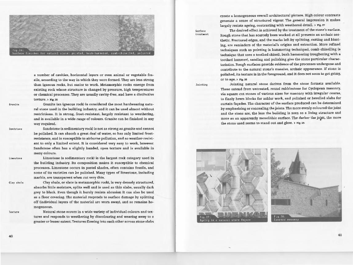
Surface treatment
Jointing
create a homogeneous overall architectural picture. High colour contrasts
generate a sense of structured vigour. The general impression it makes
largely resists ageing, contrasting with weathered detail. > Fig. 27
The desired effect is achieved by the treatment of the stone's surface.
Rough stone that has scarcely been worked at all presents an archaic aes
thetic. Fractured edges, and the marks left by splitting, cutting and blast
ing, are reminders of the material's origins and extraction. More refined
techniques such as pointing (a hammering technique), comb chiselling (a
technique that uses a toothed chisel), bush hammering (roughening with a
toothed hammer), sanding and polishing give the stone particular charac
teristics. Rough surfaces provide evidence of the processes undergone and
contribute to the natural stone's massive, archaic appearance. If stone is
polished, its texture is in the foreground, and it does not seem to get grimy,
or to age. > Fig. 26
Jointing natural stone derives from the stone formats available.
These extend from untreated, round rubblestone for Cyclopean masonry,
via square-cut stones of various sizes for masonry with irregular course,
to finely hewn blocks for ashlar work, and polished or bevelled slabs for
curtain fac;;ades. The character of the surface produced can be determined
by emphasizing or concealing the joints. The more evenly coloured the joint
and the stone are, the less the building is seen as a living structure and
more as an apparently monolithic surface. The darker the jo~nt, the more
the stone used seems to stand out and glow. > Fig. 25
41

CONCRETE ) @ Concrete is the universal building material of our age. It has marked
the development of 20th-century architecture decisively. It is an ambiva
lent material: used in liquid form, it is valued for its strength as artificial
stone. Outwardly it shows the formwork rather than its own structure.
Some people like concrete for its purist aesthetic, others find it brutal and inhuman.
Production The mixture of cement, aggregates and water determines the proper
ties of concrete. The cement acts as the binder, the water is present so that
it can set, and the aggregates cut down the amount of cement needed and
determine density, strength, thermal conductivity and heat storage capac
ity. Typical concrete has a high gross density, great surface hardness and
great strength. The usual aggregate is gravel. The structure of large and
small granules is calculated to create as few cavities as possible. The gravel
will be completely enveloped by the cement and bound to it non-positively. The smaller granule sizes help the concrete to flow more easily. )@
Aggregates The properties of the concrete are determined by the aggregates. Nor
mal concrete has high thermal conductivity and heat storage capacities.
Thermal conductivity can be significantly reduced by changing the aggre
gates, for example by using expanded clay, particularly porous clay balls
42
~ \\Hint:
Concrete is mode from inorganic materials and is non-homogeneous. Essentially it is stone
that can be moulded, and can be produced in any
shape required, like ceramics (see page 54),
and worked like natural stone (see page 39).
~ \\Hint:
The water-cement ratio (w/c) defines the pro
portion of water and cement as a percentage.
If the w/c ratio is less than 0.6, concrete
that 1s impermeable to water can be produced. Concrete can thus be used in o loadbearing
capacity, as well as taking over the function of damp-proofing.
Processing
Formwork
Reinforced concrete
or wood chips. Thermal conductivity can be reduced further by introducing
air pores as an insulation device. This is done by means of blowing agents,
which make the concrete rise like a cake. The result is called aerated con
crete. Chemical substances can also be added to make the fresh concrete
easier to work; or colour pigments to dye the concrete.
The concrete loses volume while setting, and shrinks. To prevent
cracks, sections to be concreted are defined and joints - or dummy joints,
which are indicated on the surface only - are used as a "predetermined
breaking point". The pressure of the liquid concrete, which has no inde
pendent loadbearing capacity during processing, has to be a~sorbed by a
secondary structure. The formwork must be designed to the appropriate
dimensions. To prevent vertical sections of the formwork from bulging,
formwork ties are passed through the building component to be concreted
and so the two sides of the form work are attached to each other non-posi
tively. They leave visible traces in the finished concrete. The surface of the
shuttering and its joint pattern, as well as the formwork ties, define the
texture of the visible concrete. > Fig. 30
Fair-face concrete is the negative of its formwork. Sanded, rough or
sandblasted timbers, > Fig. 29 left coated or uncoated formwork panels in
wood, metal or plastic offer a wide variety of design possibilities. The in
ternal structure of the concrete can also be revealed. The formwork sur
faces can be treated with substances that slow down the setting process.
If the surface is then sprayed with water, the gravel inside is revealed: the
result is called exposed aggregate concrete, or washed concrete. > Fig. 29
centre The surface can be sanded or struck off subsequently to show the
internal structure of the concrete. > l(ig. 29 right Concrete can also be used
entirely without a surface of its own by using permanent formwork, which
simply remains in place at the end of the concreting process.
As a simple mixture, concrete has little tensile strength, so if it is
used structurally it will always be reinforced concrete. Reinforcing steel is
introduced into the concrete at the points where loads have to be absorbed.
43
Recycling
44
The lowest possible level of concrete covering is always planned to protect
the steel against corrosion from the alkaline pH of the concrete. Concrete
and steel also work together well because the two materials have almost
the same coefficient of expansion. Textiles, or carbon or plastic fibres may
also be used for reinforcement; these will reduce the amount of covering
concrete needed and thus make it possible to produce particularly slender
components. Elephant grass (Miscanthus) is a reinforcement that regrows.
As a plant that grows very quickly, its cells store a great deal of minerals,
which help to form a non-positive bond with the cement. This reinforce
ment inside the concrete makes the initially non-directional concrete into
a directional compound material. Its loadbearing capacity can be influ
enced by moulding or by the statical height of the structure. Intelligent
moulding, corresponding with the flow of forces in the concrete, opens
up new design possibilities and can reduces the quantities of materials required considerably. } Fig. 31
Concrete stands for durability. Its real useful life is determined by
the particular way in which it is processed. The non-positive bond of steel
and concrete makes it a compound material. It is hard to introduce con
crete into a recycling programme, as the most of the energy is tied up in the
chemical process of hardening the cement. Meaningful, complete recycling
of a building component often fails because of the monolithic building methods used for concrete.
>@ MINERAL-BONDED MASONRY UNITS
Stone and massive building methods are usually associated with
natural stone and bricks . But for some time now these materials have been
complemented by mineral-bonded masonry units: calcium silicate units
are made from lime, and concrete units from cement. Perforations can re
duce weight, and embossing can structure the surface of the units. } Fig. 35
Such masonry units have come to be a common resource in the building
industry, because they are readily available, and because of the ease with
which they can be worked and processed, especially as they have a low
gross density and high strength levels. •
Production and properties
Masonry units are hardened under steam pressure at average tem
peratures of 160 to 200°C in autoclaves (gastight closed pressure contain
ers). This production method means that they shrink very little, and the
products are consistent in quality and dimensions. Masonry units are gen
erally not sensitive to moisture: in fact, their surfaces absorb it from the air
and release it back into the air again. This also has a positive effect on the
interior climate, but is undesirable in outdoor use. The binding agent used
reinforces (e.g. in the case of gypsum or lime) or reduces (e.g. cement) this
property. Calcium silicate external facing units are therefore impregnated.
Masonry units also show high capillary forces, i.e. they absorb liquids. For
this reason seals and horizontal insulating courses in rising wall have to
be planned and executed very carefully when using masonry units.
>@
~ \\Hint: Like concrete (see page 42), masonry units with
mineral binding agents consist of inorganic
mineral material. They con be jointed like
ceramics and bricks (see page 54) or natural
stone (see page 39).
~ \\Hint.:
The moisture-related properties of masonry units can be used outdoors as floor coverings,
to reduce sealing. Particularly porous cement
units ore produced to allow precip i tation to soak through into the subsoil.
45

rlt2 1c :> ''s.,r-~"·~
r~ ~~/
............... ~
r h~
Rggregates The choice of aggregates makes it possible to change the properties
of the units, especially those of concrete masonry units. According to the
type of aggregate, it is possible to produce lightweight concrete unit (pum
ice or expanded clay), granulated blast-furnace slag units (slag), or aer
ated concrete units (C02 as blowing agent). All these reduce the weight and
thermal conductivity of the units. However, the units' surface hardness is
reduced with their weight, which is an argument against using them for
exposed surfaces (e.g. as fair-face masonry). Masonry units thus seldom
develop their own properties as a wall material, and tend to be hidden under rendered surfaces.
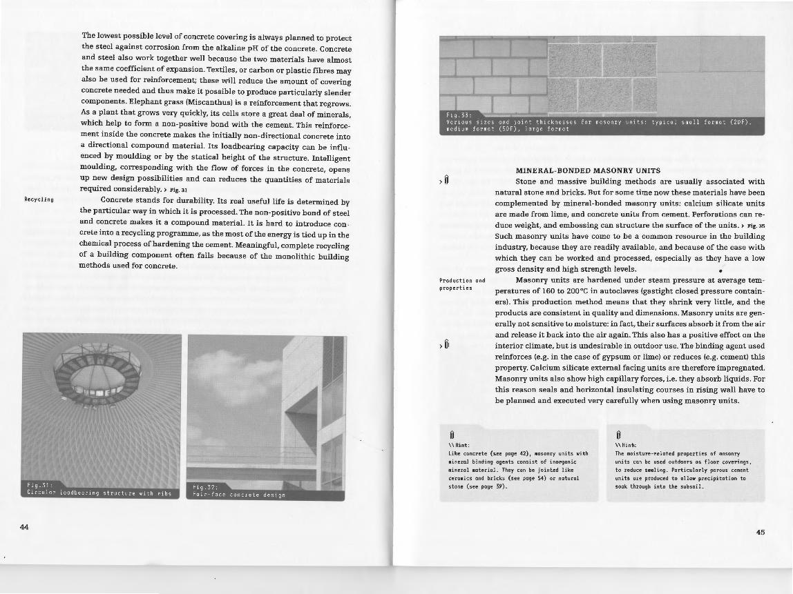
Unit formats
>@ Jointing
46
Weight reduction makes it possible to increase the format of the
commercially produced units. A workman's hand used to be the scale for
bricks, but now they are sized according to how much a worker or a me
chanical lifting device can handle, in order to speed the building process
up further. But the formats are still largely based on the rules for brick
masonry; larger formats do have their own sizes, however, derived from the
structural quality of the material (high compression strength, low tensile
bending strength), or from the customary spatial dimensions.> Fig. 34
The units' high dimensional stability is the basis for format enlarge
ment. Precise manufacturing processes can reduced the number of com
pensating joints needed. High precision compatibility means that joints
can be thinner. > Fig. 36 For interior use, this development is so far advanced
@ \\Hint:
Further information on masonry unit formats and masonry structures can be found in Basics Masonry Construction by Nils Kummer, BirkhOuser Publishers, Basel 2007.
Recycling
that only horizontal joints are needed. The kerf is then replaced with a
mortar-free vertical joint with tongue and groove.> Fig. 33 right
For bricks, the joint is typically still recessed, for stone, the joint is
protected from driving rain and other weathering, but for masonry units
with mineral binders, especially calcium silicate units, the joints also
help to protect the vulnerable edges of the units, so they should not be
recessed. This means that masonry units always look flatter than compa
rable 'bricks, and their material depth shows only at the corners. This re
duces the monolithic impression made by individual units, but for build
ings with simple cubatures the monolithic impression from a distance can
even be enhanced. > Fig. 36
This quality of flatness can be enhanced even further in the interior.
Sometimes only very narrow joints are needed because of reduced thermal
expansion as well. 'Masonry units with a ground surface, "terrazzo tiles",
show the internal structure of the material on the surface. Essentially, all
known techniques for natural stone and concrete can also be used for sur
face treatment.
Masonry units are well suited to recycling regardless of material.
The units are separated after use by detaching the jointing material and
can then be reused as they are. It is essential that the jointing material is
not as strong as the unit, as otherwise the unit will break first and cannot
be used again. Particularly light units are not strong enoug]J either, and
become non-reusable materials. Mortar-free jointing (tongue and groove)
makes a major contribution to reusability.
47

>~
>@ Classification by binding agent
Properties
~ \\Hint:
BOARDS WITH MINERAL BINDERS
Boards with mineral binders are a typical material for interior clad
ding. Such boards have become an almost universal surface for lightweight
wall and ceiling structures because they can easily be scored, sawn, cut,
drilled and milled. Plasterboard is the most common, but there are also ce
ment fibreboards, wood wool boards, mineral-bonded chipboards, fibrous plasterboards and perlite wallboards.
These boards can be classified as plaster or cement boards according
to the binding agent used. Plaster sets rapidly when used for bonding, and
is thus suitable for making boards by extrusion. The very fluid plaster is
enclosed in cardboard on both sides, and then shaped under pressure. The
strip of board is endless at first, then cut to size. Micropores in the plaster
structure establish the material's absorbent properties: it absorbs mois
ture well and thus makes it possible to control interior humidity well.
Cement bonds noticeably more slowly. It is therefore unsuitable for
an extrusion process, and has to be pressed into shape. Cement-bonded
boards are therefore stronger than the plaster versions. The material can
also be waterproofed. The strength of cement boards can be exploited for loadbearing and reinforcement.
Despite the boards being relatively thin, the material can be used
structurally if it is reinforced to withstand lateral and tensile forces.
~ \\Hint:
Mineral-bonded boards hove an inorganic mineral composition, a non-homogeneous structure,
The DIN EN 520 standard changed the old
DIN 18180 designation standard wallboard to plasterboard.
48
and are used similarly to timber products (see page 36).
~. OCC ••••• - ••••••• -c . _
,~,r~~-'~ "-'c")J
>@
Edge design
Architecture for interior spaces
~ y ~ A
X
sealing with reinforcement strip
~ I"-,_:;: /
; / ~J-·,X:. .. ~< ,:../.,t<rr- ;
i corner with edge protection
Fibrous materials are used almost exclusively as aggregates; glass fabric
is also used for perlite wallboards. This kind of reinforcement is placed
on the outside, in order to develop its own statical height. Plasterboard
goes a step further. It is reinforced by the cardboard that covers it on both
sides, making it very strong but light, and reducing its thermal conductiv
ity. A great deal of performance is lost, however, if the cardboard surface
is weakened or damaged. The surface lie of the cardboard makes the plas
terboard more efficient in one axis, so it is available in rectangular form.
Untreated plasterboard is vulnerable to water. > Fig. 37 •
Plasterboard was developed to act as support for an overlay or top
coat (e.g. wallpaper or paint). This means that areas without visible joints
are needed, with production joints that are able to accommodate lateral
expansion invisibly. Plasterboard is therefore supplied with various edge
patterns optimized for special applications, and sealed with or without
joint reinforcement after assembly. > Fig. 38
Plasterboard represents the idea of a material without any visible
properties. The plane of the material and its texture retreat completely in
favour of other materials or the way a space is perceived as a whole. White
architecture of the kind used in Richard Meier's buildings would be incon
ceivable without plasterboard. > Fig. 39
~ \\Hint:
Perlite is a natural, hydrous, glass-like
stone. Heating evaporates the water content
and enlarges the volume of the material up to
20 times.
49.

Use for foqodes Mineral-bonded boards can also express a quite different, new ma
terial quality. Cement fibreboards are available in concrete grey for use
on fac;:ades, and other colours are available as well. introduced into the
cement as pigments. They are usually flat for fac;:ade use, but can also be
corrugated for structural purposes. This increases their static height and
thus the maximum span that can be achieved. They can be overlapped and
assembled to form a continuous layer that is impervious to water.
Sound insulation The boards' surface properties also mean they can be used for sound-
Recycling
50
proofing; wood wool boards are a good example here. Their rough, open
pored surface scatters and absorbs sound. These rough, reasonably priced
boards have a crude, technical aesthetic, and make fixings and built-in
units stand out particularly. They combine well with mineral bonding
agents and are thus also suitable for permanent formwork in service rooms
or underground car parks.> Fig. 40
Mineral-bonded boards are not usually used structurally. They are
easily replaced as planking for upright walls. The boards can be reclaimed
without major material loss. Even so, their recycling quota is very low,
as the material is very reasonably priced, and creates little or no toxic waste.
} @
}~
Screed
Impact sound insulation
~ \\Hint:
PLASTER AND SCREEDS
Plaster and screeds create large surface areas without joints. They
protect the materials underneath from moisture, frost and fire, and act as
load-distributing elements.
Screed is poured on site and hardens on contact. Like all mineral
bonding materials, it shrinks while hardening, which means that cracks
can form, so contraction joints should be planned. Setting times are also
very important in the building process. It is usually possible to walk on
a cement screed after 7 days, but it needs 28 days to rea(Oh its defined
strength. Anhydrite and mastic asphalt screeds can be walked on consider
ably sooner. The elastic quality of bitumen means it can be applied more
thinly, but can be joint-free over a wide area. It can also meet reduced
soundproofing requirements without impact sound insulation, as it pre
vents structure-borne sound from being conducted.
Impact sound-insulated screeds float in sheet form on elastic insu
lation. Insulation strips prevent sound from being transmitted via rising
walls. Dry screed, made of plasterboard, for example, can be reused and
is easy to replace. Terrazzo, tile and timber screed offer surfaces with dis
tinctive material properties. > Fig. 41
~ \\Tip:
Plaster and screeds are composed mainly of inorganic materials and are similar to concrete (see page 42) in the way they are treated.
Plas~er is a standard building material. It
is worth taking advantage of the many surface variants of plaster, as this involves scarcely any more expense or effort, but makes it possible to create greater added value for the
architecture.
Their surfaces can be worked like natural stone (see page 39).
51

Plaster
Composition of plaster
Plaster protects the materials underneath it and provides homoge
neous surfaces that can also be decorative. } Fig. 43 Technically speaking,
two finishes are possible: on the one hand, plaster has an open-pored
structure and can remove any moisture that may have penetrated the ma
terial underneath it. The plaster will then tend to be fragile, and is eas
ily damaged; it is the weakest layer of the wall structure and requires
constant care. On the other hand, plaster can form a particularly strong,
dense surface that maintains its protective function for a considerable
time. This finish is very easy to maintain in the first place, but if there is
any defect the plaster has to be replaced completely, and the support is
usually damaged in the process of removing the outer layer of plaster, as this is so strong.
The plasters available are classified according to the type of binder.
Loam plaster can be used only as an undercoat and for interior work.
Moisture-sensitive plaster is also used in interiors only, but is suitable for
creative work and for fine stucco. Lime plaster types that are able to dif
fuse vapour range from soft air-hardening to hard hydraulic lime plasters.
They are used as a water-inhibiting layer indoors and outdoors. Using ce
ment as a binding agent makes it possible to produce capillary waterproof
lime-cement and cement plasters for outdoor use. Special plasters such as
renovation, fireproofing, acoustic, and thermal insulation plaster can be produced with the use of aggregates.
Plaster ground It is essential that the plaster should adhere to its ground immedi-
Plaster supports
52
ately, without becoming solid in its own right. Plaster can therefore be ap
plied only up to a limited thickness. If the ground draws too much moisture
out of the plaster, it will not solidify fully. If the substrate does not respond
to moisture at all, only a low-level, non-positive bond can be established.
The plaster ground is therefore often primed.
If the plaster ground cannot guarantee adhesion, special plaster sup
ports must be used. Plastic fabric mats or reeds then hold the plaster in
position. The principle still works if the plaster support replaces a solid
Design
Texture
plaster ground. Wire meshing is then used to guarantee loadbearing capac
ity. Rabitz plastering of this kind has a degree of elasticity that makes it
possible to damp down oscillation, and thus also deaden sound.
Plaster has a function as part of the design, as well as offering pro
tection. It creates a monolithic impression. The surface texture is discern
ible only from close to, when it becomes clear that the plaster is just an
outer skin.} Fig.44 This texture is based on the material and the application
technique: the chosen process leaves marks as a result of the interplay
betV'{een tools, additives and the hardening process. Surfaces of this kind
can be determined by random factors in the distribution of the additives
(gravel and sand), or the way the worker handles tools. Plaster can be col
oured by painting or by penetration dyeing.
The first possible texture is created directly by the way the moist
plaster is applied. It can be sprayed over large areas, or applied over small
areas with a trowel or brush. Plaster that has dried slightly can be marked
over large areas in free forms with a trowel, a wooden plank with a struc
tured surface, or special combs and rollers. Shortly before the plaster dries
out completely, the surface can be rubbed with a spongeboard for a particu
larly smooth finish. It is also possible to wash off the surface binder mask
and allow the plaster additives to show. A stonemason's skills can also be
used. } see chapter Natural stone Scraping off the surface of plaster, which is
particularly rich in binding agents and tends to accumulate tension, makes
it possible to create large areas free of shrinkage cracks.} Fig. 42
•
53

> ~
Clay os basic material
Firing and properties
54
CERAMICS AND BRICKS
Ceramics go back a very long way, with evidence available from the
4th century BC. Their name derives from the Greek "keramos", and means fired earth.
The basic material for ceramics is clay, which consists largely of hy
drous aluminium compounds, and has a flat foliar structure that makes it
plastically mouldable. The soft mass is pressed into a mould to create a
"green tile". In today's extrusion presses, the mouthpiece can be changed to
alter the cross section of the product; the extruded ribbon is cut to length
according to the product size required.
The product does not become water-resistant until it has been fired.
The foliar clay structure fuses at a temperature of about 800 °C. The earth
enware produced in this way has a high capillarity. From about 1200 oc the
sintering process takes place: the aluminium compounds fuse to produce
a vitreous structure. Cavities are surrounded, and the capillarity thus re
duced to a minimum, giving a frostproof sintered product. Ceramics lose
volume in the firing process. This cannot be predetermined, and means there
are high dimension and product tolerances. Fired ceramics are subdivided
into ordinary and fine ceramics by grain size and by the degree of porosity.
> Fig. 45 They have high gross density, hardness, compressive strength and
abrasion resistance. Like stone, they have low tensile strength.
fi \\Hint:
Ceramics are composed of inorganic material. Their structure is similar to that of gloss (see page 62). Bricks ore used in simi lor ways
to natural stone (see page 39) and mineralbonded masonry units (see page 45).
I ~ ~ ~e I j/"'~~e '\.0\.e~ <-o"'~
(;0 U c,O eoo,e
Surface
Brick
Texture
Solid construction
aesthetic masonry courses
Surface colour and texture are produced by the moulding and firing
process. An additional possibility is surface coating, where the product ac
quires a hard ceramic covering, the engobe. This then determines the hard
ness, smoothness and colour of the ceramics, and can seal the surface of
earthenware, for example. Ceramics can also be treated using techniques
such as flaming.
The dimensions of bricks are subject to a strict octametric system.
Normal and thin formats, much used in fair-face masonry, have been re
placed by large-format bricks or blocks when they will not be visible, al
though they use the same system of measurements so that the different
wall courses can be matched. When designing a masonry ~uilding it is
worth using the octametric system from the outset, so that any joints can
be handled sensibly at a later stage. Bricks can only be pressure-loaded,
so it is important to work out the pressure forces first of all when working
with masonry.
The texture of brick masonry is determined by the jointing of the
bricks, with stretcher and header courses keying the masonry together.
> Fig. 46 The colour of the joint, the joint pattern and the way it is executed
determine how the dimensions and material depth are perceived. The joint
is often recessed, which reveals the depth of the masonry unit. In this
way, an individual unit can develop a solid quality of its own, as well as
the whole area of wall, and at the same time protect the joint against the
weather. The usual joint thickness of 1 em derives from the high tolerances
in brick dimensions, and differences in shape can be compensated for by
the joint design.
Bricks are used in a variety of ways. New developments, featuring
increasingly large formats and lowe:.;: weights, have speeded up the build
ing process. Low weights and low conductivity are also thermal protec
tion requirements. To improve them, and to meet raised thermal protec
tion requirements for fa~ades with single-shell masonry, wood chips or
polystyrene beads are mixed with the clay; these then create cavities when
55

Facing masonry shell
the material is fired. The gross density can be further reduced by using
extruder press cross sections with a high proportion of air chambers.
If the typical visual effect of brick is to be combined with high ther-
mal protection levels, an insulating layer must be planned in the interior
of the wall. To avoid having to build two walls, the outer part of the wall
is attached to the inner one. Only water-resistant, frost- and efflorescence
proof facing bricks or clinker bricks can be used for this purpose. The
facing masonry shell is usually just one brick thick and is held in place by
stainless steel masonry ties. The problem of apertures is that the lowest
stones have to dissipate any compressive forces acting on them, either to
beams or to specially suspended steel sections. Expansion joints should be
allowed for every 5-12 m within the facing shell.> Fig.47 METALS Ceramic panels Ceramic panels suspended on metal sections are also used for The largest group of chemical elements, metals, are divided into
heavy metals with a gross density of more than 4500 kg/m3 (lead, copper,
zinc, iron), and light metals with a low gross density (aluminium, magne
sium). As iron is the metal most commonly used in building, an additional
distinction is made between ferrous and non-ferrous metals.
Roof tiles
)~
Recycling
56
fa~ades. They provide protection against the weather, and are very thin,
thus considerably reducing the loads to be dissipated. The ceramic panels
are not bound positively, but create a water run-off layer through over
lapping and joints. Such fa~ades seem light in contrast with the massive quality of masonry.
Roof tiles follow a similar construction principle. Flat roof tiles such
as the flat-tail need a high level of overlap and are used only on steep roofs.
Roof tiles with overlapping lips can be laid at considerably lower pitches. > Fig. 48
Bricks, a material with high primary energy consumption and high
>@ Properties The special properties of metals are high density, high compressive
and tensile strength, high melting point, high thermal and electric con
ductivity, a metallic sheen, and elasticity. Because these properties are
derived from their crystalline structure, combining several metals (alloys)
in a crystal lattice does not unite their properties, but creates j. quite sepa
rate set. Small additions can therefore be used to set properties of alloys durability, are suitable for product recycling provided they can be separated very precisely. There are 2000 known alloys of iron alone, including various
from the jointing mortar. Ceramic panels and roofing tiles that are used with qualities of stainless steel, which is weatherproof and retains its sheen open joints and without mortar are ideal for recycling and repairs. permanently.
Iron ond steel Ferrous metals with a carbon content of less than two percent are
@ \\Hint:
known as steel. This is more elastic than iron, can be welded, and has a
higher tensile strength. Because of their great strength and weight, iron
and steel building components are geometrically optimized for static ef
ficiency. The shape of I-girders or trapezoid sheets provides information
about areas of structural use and minimizes the amount of material used.
Iron oxidizes, and therefore needs to be protected from contact with the
air.
@ \\Hint:
Further information on roof tiles con be found in Basics Roof Construction by Tonja BrotrGck,
Birkhiiuser Publishers, Bose! 2007.
Metals are inorganic materials; they have a
crystalline structure and ore smelted, in a simi lor woy to gloss (see poge 62).
57

Zinc, copper and lead
Aluminium
Yielding
)Q
58
Zinc and copper are weatherproof and easy to work, and thus used for
fagade cladding, covering sheets and roof drainage components. In build
ing, silvery zinc is almost always used in the form of an alloy with a low
titanium content (titanium zinc). This reduces thermal expansion, improves
elasticity and makes the material weldable. Copper gleams reddish-brown,
and is much sought after in building for its appearance and good weather
resistance. Matte-grey lead is not strong; it can be cut with shears and
shaped by hand. Lead is used for roofs, particularly for parts that would be
very laborious or expensive to make mechanically out of other metals. How
ever, lead is toxic: abrasion leads to its accumulating in the food chain.
Aluminium has a low gross density and is therefore a lightweight
metal. It can be used wherever reduced weight and weatherproof qualities
are important, especially for fagade elements. Even a natural oxide layer
makes the material weatherproof; technical oxidization (anodizing) can re
inforce this layer and introduce colour.
One particular temperature-dependent property of metals is called
yielding. Metals respond to forces acting on them by plastic deformation
accompanied by a sudden loss of loadbearing capacity. Although metals
are not combustible, yielding means that they must be effectively protected
from fire.
Q
\\Important:
Loodbeoring metal sections must be protected
from fire. Fireproof cladding or special points
are used for this purpose; such paints foam
up in case of fire and create a protective
layer.
Extraction
Corrosion
Only precious metals like silver, gold and platinum have such a low
reactive capacity that they appear in their pure form in nature. All other
metals are present as ore in compounds of carbon, oxygen or sulphur, and
have to be separated from these before production. Damage to the land
scape when mining ore, and the amount of energy needed to extract metal
from ore, create high levels of environmental pollution and expense. The
costs and benefits of using metal must therefore be weighed up with due
care. ·on the other hand, reuse of metals has made very great progress. Ty
ing them into material cycles improves their environmental impact. > see
chapter Material requirements, Environmental pollution
Base metals react with atmospheric gases and water. When two met
als touch, the less noble metal will pass electrons on to the more noble one
whether this is desirable or not, and only the less noble metal corrodes. As
well as having a colour of its own, the corroded layer may have particular
properties in relation to water. In some metals like aluminium, copper, zinc
and lead, this produces a stable, protective structure that envelops the
metal core. For copper and copper alloys such as bronze, a grey to green
patina, sometimes uneven, forms over time. > Fig. 54 Weatherproof steel pro
duces a protective layer of reddish-brown rust, although this lasts only if
the surrounding air is not too moist. > Fig. 49 left Sheet metal that already
has a patina is available on the market so that this patina can be exploited
deliberately. • Normal iron does not form a stable protective layer, but rusts. Paint
or powder coatings are therefore used to prevent it coming into contact
59

Shaping processes
Mechanical processes
Connections
>~
Constructions
60
with air and water and corroding. This may mean that it loses its special
effect. Galvanization provides a protective metallic coating that restores
the metallic appearance.
We distinguish between hot and cold shaping processes. In cold
shaping the structure of the atoms within the metal lattice is rearranged,
thereby increasing the metal's strength. Rolling produces simple sheets.
Commercial steel girders and shaped metal sheets are rolled into the
desired form over several stages. Extrusion produces components with
complicated cross sections. Here, a solid metal bar, usually aluminium or
another non-ferrous metal. is pushed through a template under high pres
sure. Drawing produces wire and rods, and thus also structural steel for
reinforcing concrete. Forging using a hammer and anvil can be either a
cold or a hot process. Moulded parts and complicated structural connect
ing elements are cast in a negative mould. Tin and copper alloys are suit
able for producing particularly fine cast parts, and cast steel for complex
connecting elements that need to withstand high loads in steel and timber
construction.
Mechanical processes include a wide range of chip-producing (sub
tractive process producing shavings) techniques: drilling, milling, sand
ing, turning, sandblasting, filing and sawing. Bending, edging, stamping
and welting produce new shapes mechanically. Shaping and mechani
cal processing can also produce semi-finished metal products such as
stamped sheets, expanded metals, metal meshes, and many other prod
ucts. > Fig. 50
Metal parts can be connected temporarily or permanently. Screws,
nails, rivets, pins, welts and clamps are temporary connections. Permanent
connections are created by various welding techniques, soldering and glu
ing.
Metals are highly efficient and can therefore be used in very slender
forms. They can be pressure or tension loaded. Ferrous metals are gener
ally used for structural sections because of their strength. Cast iron car
ries the imprint of the mould and can stand very high compressive loads,
~ \\Hint:
To improve the reusability of metals,
structures should be easy to dismantle and
separate from non-metal building materials.
while steel is easier to mould for structural and design purposes, and is
more elastic. > Fig. 52 The appearance of steel elements and structures can
illustrate the flow of forces very well. Here, bases and bearings are particu
larly important. They demonstrate the transfer of forces, especially when
there is a change in the loadbearing material. > Fig. 51
Fa c; ade cl adding Very little thickness of material is needed to cover an area and guar-
antee protection against the weather. The sheet metal used simply forms a
skin. Here, the metal is a covering, and a weatherproofing device. Self-sup
porting fal(ade elements in steel or aluminium can be produced flat, but
to save material and weight they are usually shaped, i.e. edged or convex.
Highly elastic metals such as copper or titanium-zinc can be shaped when
cold, and are therefore commonly used for fal(ade cladding. When used
flat, the sheets can be welted on site (bent overlapping), and can then cover
almost any surface shape and follow it in their welted form.> Fig. 53
Metals can also be designed to admit light into buildings when used
as fal(ade cladding, in the form of expanded metals, aerated metals or metal
mesh. The metallic sheen can play a role, as it emphasizes the particular
properties of the material. and can be used to direct light into the depths
of the space.
•
61

> ~
Properties
> ~
Composition
Floot gloss process
fi \\Hint:
GLASS
As a transparent building material, glass plays a key part in archi
tecture, because its invisibility means that it can almost dissolve the mate
rial quality of the building. It forms an effective spatial conclusion, while
fulfilling the basic human need for daylight.
Like all materials, glass absorbs radiation. This takes place in the
non-visible part of the spectrum, and so glass appears permeable to light.
As it cools quickly in manufacture, a crystalline structure can form. It is
thus an amorphous building material. Glass is dense (2490 kg/m3), hard
and brittle, abrasion-resistant, and has high compressive strength. Be
cause it is so brittle, and its surface tension resembles that of water, it can
withstand little tensile and bending load. The surface of the glass is brittle
as well, and it can therefore be cut by scoring the surface, which is then
broken along the score line.
Quartz sand is the principal raw material of glass. Simple building
glass, also called normal glass, is made from silicon dioxide, sodium oxide
and calcium oxide. The particular composition determines the properties
of the glass. > Tab. 7
Glass used for building is usually made by the float glass process.
Glass is floated on a bath of molten tin. The lighter molten glass floats
to the surface, where it slowly cools down and solidifies. During this pro
cess it is slowly drawn from the completely level bath. The stream of mol
ten glass forms an endless sheet, which is immediately cut into transport
fi \\Hint:
Glass consists of inorganic material, and is
amorphous. Plastics shore many of its proper
ties (see poge 66), ond its manufacture is
similar ta that af metals (see page 57).
Gloss is dimensioned not according to its
strength, but in terms of the likelihood of
breaking. Thus it is octuolly overdimensioned.
62
Pressed/rolled gloss
Cost gloss
Foom gloss/ gloss fibres
lengths of up to 7.5 m. The glass produced in this way has a high surface
quality and is eminently suitable for further processing.
Glass can also be shaped by rollers or presses. Rolled glass may be
decorative and has ornaments or structures; safety glass with a built-in
wire element; or figured glass. These products are U-shaped in cross sec
tion and can be installed to be self-supporting. If they are installed verti
cally, an endless band of glass can be created.
'In casting, the molten glass is poured into a mould and hardens
there. Glass bricks consist of two glass half-shells pressed together. These
bricks can be jointed like masonry. > Fig. 55
High-quality pressure- and waterproof transparent insulating mate
rials can be made from glass or recycled glass by a foaming process. Glass
fibres are produced in many versions to conduct light and for reinforce
ment purposes.
Glass finishing Before being used for construction, glass is often processed further
Semi-finished gloss products
Tob.7:
as required, for example by thermal treatment, surface coating or lami
nating. Thermal treatment produces a particular surface tension. The re
sult, toughened safety glass, does not form sharp edges when it breaks.
Heat-treated glass breaks into larger pieces than toughened safety glass.
Enamelling (melting a glass powder on to the surface), fusing (melting on
pieces of glass). obscuring processes, or screen printing can create par-
tially transparent, translucent or opaque surfaces. •
Laminated safety glass and insulating glass are produced by com-
bining various types of glass. For laminated safety glass, several layers of
glass are bonded together with plastic film. In case of breakage, this has
a residual loadbearing capacity, which makes the glass useful for stati
cal purposes, up to the level of bullet-proofing. Insulating and thermal
Selected types af glass and their uses
Glass type Changed co1position
Borosilicate gloss Added boric oxide
Quartz gloss Added silicon dioxide
Leod gloss Added leod dioxide
Cleor gloss Added iron oxide
Coloured gloss Added iron oxide
Added chromium oxide
Added copper oxide
Added cobol t oxide
Added silver oxide
Effect
Heot resistent
Heat resistant,
high transmission
High light refraction
Particularly colour
neutral gloss
Green to blue 'tinge
Light green tinge
Red tinge
Deep blue tinge
Yellow tinge
Use
Fireproof glass
Energy gain systems
Lenses, decoroti ve gloss
Fo<;odes
Decorative gloss
Decorative gloss
Decorative glass
Decorative glass
Decorative glass
63

>~
Glass fixing
Transparency and reflection
64
~ \\Tip: Light refraction and anti-dazzle effects are
not usually fulfilled by the gloss itself, but make a crucial contribution to its material
effect. The greenhouse effect means that glass itself can become an energy-gaining
system.
insulation glass combines two or more glasses with a gap that consider
ably reduces the glass's thermal conductivity, especially when filled with
inert gases. Coatings can reflect radiant heat; solar control glass reflects
some of the solar radiation outwards, and thermal insulation glass main
tains the ambient temperature. Special glasses for improved soundproof
ing and fireproofing are available, and adaptive glasses accommodate to
their environment. It is important that glass is mounted without tensions to avoid ten
sile and bending forces. It can be supported along a line by pressing or
bonding, and at certain points by chocking (wedges in a frame), spider ele
ments (multi-foot elements for combining panes of glass), or clamps.
Glass's transparency is always in the foreground, along with the
desire to fix it as unobtrusively as possible, so that the whole loadbearing
Translucency and layering
structure dissolves visually. A typical post-and-rail fa<;:ade can be ex
ecuted in glass, or replaced by cable systems. > Fig. 56 But in fact it is
impossible to dematerialize the architecture with glass. The eye cannot
equate shaded areas in the depths of a space with the outside space.> see
p. 12 The rhythm of day and night means that this relationship is always
weighted differently for the building. From the darker side, the percep
tion is better up to the point where the building is translucent from one
side ·only. The other surface of the glass begins to reflect its surround
ings. Reflecting glass surfaces can also be created deliberately. Buildings
then make less of an effect, or blur into the sky. Mirror surfaces can be
disturbing for viewers, because they sense they could be watched without
their knowing.
Partially transparent materials can mute the imbalance brought
about by the day-night relationship, as only shadowy effects are created.
In such cases, a fa<;:ade becomes a functional print of the building in the
outdoor space, any movements are perceived, and so it is possible to see
how the building is used. The material behind is obvious as a layered struc
ture, without having to reveal all its properties in terms of texture and
design. This sketchy view through the building fires the viewers' expecta
tions, which can either be met or contradicted subsequently. The extent
of the view through the building can be reduced so that only light passes
through, i.e. it seems translucent. This reinforces the spatia'!. impression
along with the expressive quality of the materials on which the light is
shining. > Fig. 57
65

PLASTICS > ~ Plastics are the most recent group of materials in building history.
Their development from natural raw materials such as rubber started in
the mid-19th century, but their use in architecture did not reach its pro
visional peak until the futuristic designs of the 1960s. Plastics had a poor
reputation until the late 1980s because of technical faults in the material.
but this has now largely been overcome. They are an up-to-date material
for many building components, and act unobtrusively as technical materi
als. Properties Although their properties can vary considerably, the following holds
for almost all plastics: they have low gross density and thermal conductiv
ity, a high coefficient of thermal expansion, high tensile strength, and are
resistant to water and many chemicals. There are restrictions relating to
the long-term service temperature: if it is too high they lose their strength;
if it is too low they become brittle. Three groups can be distinguished, ac
cording to macromolecular structure.
Thermoplastics Thermoplastic macromolecules tangle around themselves without
66
forming chemical bonds. As the temperature increases, they first become
elastic, then start to melt. Their elastic properties are useful for sealing
~ ~ \\Hint: Plastics are organic compounds, but they have no defined structural composition. They ore on important raw material for textiles, similar to metals in the way they con be shaped (see
poge 57) ond to gloss in their structure (see
page 62) ond con also be worked similarly to
timber products (see page 36).
\\Hint: Plastics are sometimes known by trade names, details of their composition, or an abbrevia
tion according to composition and manufacture. The abbreviations offer the quickest and simp
lest way of making comparisons.
> ~
Thermosets
Elastomers
Production
and protecting strips in polyethylene (PEl. PVC or ETFE strips, or for floor
coverings. > Fig. 60 left Amorphous thermoplastics such as PMMA (acrylic
glass) are transparent, hard and brittle. > Fig. 60 left Polycarbonate (PC).
which has crystalline as well as tangled structures, is stronger, but only
translucent. The strength and hardness of thermoplastics is used to raise
the air volume to an extreme degree by foaming, thus increasing their insu
lation properties, e.g. for polystyrene (XPS I EPS) or polyurethane (PUR).
Thermosets have three-dimensional cross-linking. They are produced
under pressure, at a high temperature and using chemical additives (hard
eners). In particular, they include the epoxy resins (EP), used.for resistant
coatings and bonding. Combined with glass, carbon or aramide fibres they
produce highly efficient materials for loadbearing structures.
Elastomers consist of cross-linked low-density molecular chains.
Rubber is used for floor coverings and insulation strips, because it wears
well and resists chemicals, and its elastic properties provide sound insula
tion. Silicones (SI) behave similarly to elastomers, although their structure
is based on silicon rather than carbon. Their high temperature stability
makes them preferred seals indoors and outdoors, and they are suitable as
fa~ade jointing mastics.
Plastics are generally produced from mineral oil, but they can also be
made from renewable raw materials. A basic material is initially produced,
usually in granular form, and then moulded into a semi-finished product.
Plastics can be prepared industrially using additives to give them indi
vidual properties, and they can be produced in different colours .
Shaping methods Shaping methods include extrusion (shaped by a mouthpiece in a
press). injection moulding (pressed into moulds under pressure and at
a high temperature). calendaring (rolling and stamping), expansion and
foaming. Extrusion presses can produce multi-chamber sheets or sections
with cross sections of almost unlimited complexity.> Fig. 60 centre Flat strips
and sheets are rolled out; their surfaces can be stamped. Some sheets are
formed with construction in mind, e.g. wide-span corrugated sheeting.
67

Floor coverings can be specially surfaced to increase slip-resistance. > Fig.
61, centre right Injection moulding allows considerable design freedom, al
though it must be borne in mind that the product has to be removed from
the mould after hardening. It is possible to produce moulded parts like
handles in this way, as well as structured sheets and much else. > Fig. 6Jleft
Post-processing A special technique for thermoplastics is thermoforming, also known
Jointing
Recycling
68
as deep drawing. Here, the thermoplastic is heated, pressed over a special
mound or drawn into shape in a vacuum. >Fig. 60 right Free forms, such as
for designing large areas, can be created in foamed plastics by compu
ter-aided three-dimensional mills; such products are used as underlay for
solid coverings. >Fig. 63
Flat sheets are mounted like panes of glass. > seep. 62 If sheets have
been shaped, their edges are usually formed so that the sheets are joined
non-positively on an axis one below the other. Corrugated sheets form a
water-bearing layer by overlapping. > Fig. 60 centre Strips and films can be
joined by gluing, vulcanizing or welding. Overlaps or welded seams pro
trude above the surface. > Fig. 60 left Welding can be done crudely by raising
the temperature and exerting pressure, but it can also be tightly controlled,
as in high-frequency welding. The ends are usually given metal clamps.
The primary energy content of plastics is usually low, as is their du
rability in relation to other building materials. Thermoplastics that have
been used particularly homogeneously can be cleaned and then reused. But
the most common type of reuse is incineration to produce energy.
) @
Production
Basic materials used
) @
@ \\Hint:
TEXTILES AND MEMBRANES
Human culture has known textile structures from its earliest days.
Tents were the nomads' ideal accommodation : they were easy to trans
port, could be pitched and struck within a short period, and were easy to
produce. Textiles, and particularly carpets, became the simplest way of
defining rooms in these cultures. Textiles are still used in today's building,
although they are used differently.
The term "textile" comes from the Latin and means woven or plaited,
regardless of the material used. If the raw materials used for textiles are
arranged within a two-dimensional structure, they are kno~n as woven
fabric. Unordered, homogenous structures in which the fibres are tangled
up with each other are known as felts and fleeces. Their three-dimensional
structure makes them suitable for construction as well, for separating
parts of a construction or providing sound insulation, for example.
Natural fibres spun into threads are the most usual basic materials
for textiles. If tactile properties and moisture resistance are particularly
important, cotton and wool are the major raw materials. If the textile has to
be particularly hardwearing (e.g. for floor coverings), rougher fibres such
as coconut or sisal are used. These natural fibres can be attacked by fun
gus, bacteria or insects. Artificial fibres are usually tougher; those made of
polyesters or nylon are particularly resistant to tearing. If coated, they can
@ \\Hin~:
Textiles and membranes do not have a defined composition or structure. They can be produced from natural fibres, plastics (see page 66) or
metals (see page 57).
Rll textiles con be chemically treated or
coated to improve their properties. However,
these layers may contain toxic substances.
Labels can provide a certain degree of trans
parency about the production processes.
69

Properties
Joining
Membranes
70
be waterproof and yet open to vapour diffusion. Fabrics can also be made
from metal wire, in steel or copper, for example. These are very strong, and
can be woven to a high degree of translucency.
Textiles are soft, and warm and pleasant to the touch. They acquire
their properties from the way in which they are made and from the basic
material. If their prime function is not an aesthetic one, they are known as
technical textiles. They can be used to weatherproof an area, but can take
only tensile loads.
Textiles are usually sewn together. Seams can be treated artfully, be
emphasized by the colour of the seam, or be particularly unobtrusive if
they are sewn on the reverse side. If textiles are to function as stretched
surfaces, the support must be linear. Point supports are weak points, so the
forces generated have to be distributed over a wide area. Eyes, darts and
reinforcements can be used for this purpose. Straps or guys can be used
to dissipate forces. Textiles can be deployed in a variety of ways, but those
listed below are probably the most common.
Translucent membranes use very little material but offer good weath
erproofing and are suitable for controlling daylight. They work particularly
well for temporary structures, in the form of tensile-loaded two-dimen
sional structures. Fabrics, which can dissipate forces through warp and
weft (the manufacturers' name for threads turned through 90°). are particu
larly suitable for this application. Plastic films can be used as an alterna
tive to textiles. Membrane structures require three-dimensionally curved
surface geometries, to generate tensile forces throughout. Curves running
counter to each other (e.g. saddle forms or hyperbolic paraboloids) stabilize
the membrane without additional construction. > Fig. 66 But membranes are
always curved at their extremities: if lines were kept straight, the tensile
forces would soar almost infinitely, or the membrane would tend to flutter
because of the reduction in tensile forces. So only a few points have to be
defined for load distribution. Meanwhile, surfaces that are curved in the
same direction, like domes or cylinders, need a secondary structure, whose
support points and lines then determine their form. > Fig. 67
Rdoptoble structures
Multi-layered membranes
Because of their low weight, membranes are also well suited for
adaptable structures like roofs whose folding or expansion mechanism has
to match the volume of the folded membrane. Thin films and coated glass
fibre fabrics are unsuitable for use here, because they are insufficiently
crease-resistant. Multi-layered membranes can provide heat insulation and thus also
be used for stationary structures. > Fig. 66 Here, they achieve ratings be
tween 2.7 and 0.8 W/m2K. However, allowances must be made for leakage,
so the volumes must have a constant supply of air. With regulated venti
lation, controllable solar protection systems in double- and triple-layer
membrane constructions can also be produced. The individual membranes
are printed with staggered solar protection patterns; changes to the mem
brane volumes regulates the way these patterns relate to the position of
the sun. > Fig. 65 left
Interior finish Carpets and felts are among the most common floor coverings, be-cause they offer a high level of comfort in terms of tactile experience and
room acoustics, and make the dwelling feel cosier. If fabrics are used to
cover seats or handles, the substructure is covered with cushioning made
of a foam material or felt, to emphasize the softness and warmth of the
material. Textiles are also suitable for flexible built-in structures and cur
tains, which can be used to regulate the extent to which a room can be seen
into or out of. thus completing the overall architectural effec;t. > Fig. 65 right
When closed, they present a translucent surface, and when open, the fall
of their folds creates a three-dimensional effect.
71

72
>@ Design strategies
>@
Context
~ \\Hint:
DESIGNING WITH MATERIALS
Designing means developing something unbuilt into something built.
Its particular quality is that the building is not there- or not there yet. No
one can live in it, no one can be aware of it. And yet it does already exist
in the form of sketches, drawings, models and texts. The ground plan, the
view· of the fa<;:ade, shape and colour, expression and atmosphere, wood or
stone, concrete or steel: the whole building is there before us, devised and
designed. It is there- and yet not there. Building is inseparably linked with
material. Its material quality is apparent even at the design stage- some
times only in a shadowy form, sometimes very precisely. It is the material
that determines the effect the architecture will make: architecture for its
part is an inherent harmony of task, form and material.
But how does the designer come to give expressive and conclusive
form to his or her material? Essentially, two strategies can be distin
guished: the material can be the starting-point for a design, or the design
process initially takes place quite independently of any ideas about ma
terials. If the materials are the first decision, the design and structure
emerge from their properties and significance. > see p. 31/32 A design that
emerges independently of the material must be translated into material
terms later, which can sometimes mean adapting the design .•
GENERAL CONDITIONS
Design and material are always tied in with a specific context, which
is explored at the beginning of the design process. The surroundings are the
most important general condition: in particular, the buildings surround
ing the new one, their scale, proportions, and of course the quality of their
~ \\Hint:
Even if the first sketches ond design ideas do not have to carry any direct evidence of mate
rial quality, the completed design drawings
will always identify or imply materials. The only way to experience material quality sen
sorily is by having the materials themselves.
Producers or processors will supply material
samples, usually free of charge. Experience is
thus gradually accumulated, along with a collection of materials.
Trying out both the strategies for determining
material quality is recommended. In this way,
designers will find their own approach some
where in the bandwidth from initial basic moterl-al-reloted ideas to abstract ideas that emerge without any particular material in mind. This does not imply an inflexible statement
about design: the appropriate strategy always depends on the brief as well.
73

Existing buildings
Changeable general conditions
74
materials as well. Site-specific conditions such as climate and weather are
crucial, as well as materials that occur naturally in the immediate vicinity.
The brief also provides a framework: the function of the building and its
importance, the spatial programme, and the funds available for building
and running it.
The brief will often stipulate that an existing building or buildings be
included or replanned; their structure, construction and material proper
ties are then the starting-point for any subsequent decisions about design
and materials. There are other general conditions that planners have to con
sider as well: traffic, the users' requirements, planning and building law, or
specific technical requirements. The demands made on the design, the ma
terial and the structural elements derive from the sum of these conditions.
The architect's task is now to explore the properties and limitations of each
material selected and to translate them into a coherent construction.
For example, a site or a brief could suggest building in wood. If this
organic material is exposed to moisture, this can encourage the growth of
fungi and bacteria, which will damage the wood. > see chapter Wood To be used
outside, it will have to be protected from the weather. For the design, this
means detaching the timber structure from the ground, i.e. raised or placed
on a solid base. > Fig. 68 Then the building and fire protection regulations
applying to wood have to be observed: as a combustible material, it cannot
be used in escape areas. If fireproof cladding is undesirable, or sprinkler
facilities cannot be built on the grounds of expense, in an extreme case us
ing wood may be out of the question.
Many specific requirements are subject to change, and are not always
free of contradictions. On the one hand, safety considerations continue to
increase, as in fire protection, and so does ecological awareness. Users
demand more and more comfort; more durable materials are sought after,
as are less need for maintenance and more air conditioning. On the other,
building materials no longer have to be sourced locally, as transport is
easy; local identities are fading away, a random quality is creeping into the
choice of materials: "anything goes" ... > see chapter Material requirements
Designers have to weigh up the various general conditions carefully.
They must develop a sense of how technical developments and social re
quirements could change building in the future. But new and innovative
materials, construction methods and technologies can be set against the
increasing need to reduce everything to the important and familiar in this
increasingly unmanageable media society; and this make things easier to
handle. These two opposite poles can show the way as helpful "guardrails"
against which designers can measure their work as they move towards a
position of their own and wish to test its appropriateness. This helps to
formulate architecture precisely, in a way that is both close to reality and
oriented towards the future.
Tradition and location
Material innovation
BASING DESIGN ON MATERIAL
In historical buildings, the choice of material was usually based on
what occurred naturally in the immediate vicinity of the buil.J.ing site; this
determined whether the design could be realized or not. Local building
traditions thus developed with close links to native materials . Local avail
ability and long experience with the few materials available shaped the
approach. Today, transport distances do not seem to be important at all,
but regional building methods often continue to be very important, as they
convey links with the locality and the region and fit in with the surround
ings: think of a wooden house in a wooded area, a stone house in a rocky
landscape, a brick building in a clayey region. > Fig. 69
An unusual or completely new material can, however, also be the
starting-point for a design. This approach is never simple, because the gen
eral conditions have to be blanked out completely at first, e.g. the typical
use of a particular material or the common urban development approach
to the context in question. Appropriately careful consideration should also
be given to when and how the material's use is viable. For example, it might
be possible to achieve new levels of comfort or durability, surface quality
or cost saving with a material that is new or not customarily used in the
building sector. A material that is initially unusual, used surprisingly, can
be particularly expressive, and create a special atmosphere that could not
be achieved by the more common one. >Fig. 70 It is still possible to address
links with the locality in this way. It is precisely when classical form and
innovative materials come together that architectural moods and pictures
75

are created so that a building's materials make it shine. Thus, the simplest
saddleback roof volumes, realized in an unusual way with gleaming metal
surfaces or clad in coloured panels, can convey this charming aspect of the
unknown and ultimately still be expressive. >Fig. 62
MATERIALIZING THE DESIGN
Materialization As has already been mentioned, the design can also be developed in-
Dialogue of design and mater i al
76
dependently of the material. The way materials are deployed subsequently
plays a subordinate role. The designer first of all devises forms, spatial
connections and links between inside and outside. The space is developed
in terms of perceptual ideas; the areas creating the spaces and their effects
are the prime consideration. The planner then chooses materials that will
support the design's impact on this basis alone. Endowing the design with
material quality issues a challenge to cross a threshold, to make the ideas
more precise and concrete. Intentions are concretized by defining materi
als. >Fig. 72 Things acquire a presence, gradually take up the correct posi
tion in the building, and adopt the right shape. Material bestows meaning,
and the visual impression, smell, tactile properties and acoustics become
concrete.
The designer explores the materials' inherent properties. The inter
nal forces relating to loadbearing and holding in place start to show, the
principles of jointing, and ultimately also the work enshrined in things.
Construction principles, component sizes and the nature of the material
help to strengthen the inner logic of the design. But design, a constant in
terplay of emotion and intellect, only seems for a while to incline towards
Optimization
the rational side. Using the choice of materials to comprehend and order
the design can generate new emotions and ideas and offers major oppor
tunities to improve its quality. It is helpful to check that the design as
drafted is compatible with the properties of particular mat8'rials. For ex
ample, long, linear designs are well suited to directional or fibrous materi
als, while massive volumes suggest mineral materials. > see chapter Typologies
of building materials, and Fig. 71 A loadbearing structure, for example, develops
from the structure of the design, the chosen materials determine the look
of the surfaces, and thus achieve the desired effect by the way they work
together.
It is advantageous if th~ design responds to the chosen materials,
changes to accommodate the limitations imposed by their properties, and
thus gains quality and character. The design formulates demands on the
structure, and identifies any restrictions in the choice of materials. For
example, sections of the building that form the exterior limits of interior
spaces have to meet heavy demands: they must be weatherproof, wind
proof and ensure that interior temperatures are comfortable. Loadbearing
sections must be stable and dissipate any forces acting on them without
causing damage. This and other demands (such as cost) limit the range of
materials that can ultimately be used to implement the idea behind the
design. This kind of approach to materials gives the design an inner logic.
>Fig. 73
Transfaroation Another possibility is to use the design to develop the materials. It
is increasingly possible to adjust a material's properties, and in future it
is conceivable that they could be tailor-made. The creativity of architects,
77

>~
Monolithic building
78
working with the specialist knowledge of engineers and manufacturers,
can push forward the development of new, highly efficient materials. This
can enrich the design repertoire and improve the quality of building; or if
the issues are not properly thought through, can lead to random choices and conceal technical risks.
DESIGN APPROACHES
Regardless of the design strategy chosen, decisions about materi
als, about their precise and meaningful use, make a crucial difference to
the quality of a design and ultimately of the building that emerges. In the
context of architecture, buildings can take on particular properties that
are not necessarily inherent in them. They can also convey ideas that go
beyond the design, and with them acquire a new sense of significance. Ma
terials are central elements in the language of architecture. Their vocabu
lary demonstrates some sets of rules that apply particularly to material
quality, which will be examined in more detail below.
Monolith (sculptural effect, physical presence) Monolithic building is a material-dependent design principle. Often
only a limited range of materials was available locally, and sometimes only
a single material could be used for all building needs. The Egyptian pyra
mids, the Pantheon in Rome and medieval castles appear, and are, mono
lithic. > Fig. 74
If a single material is used, it dominates the statement the architec
ture makes. In modern architecture, fair-face concrete buildings seem to
interpret the term "monolith" almost literally: the building looks as though
it is made "of one stone", here artificial stone. > see chapter concrete A mono
lithic impression can also be conveyed by other material, such as brick,
> see chapter Ceramics and bricks and so can natural stone used as a curtain wall,
erected homogeneously with discreet joints. > see chapter Natural stone The aim
is always to create a completely homogeneous spatial effect. Architecture
always tries to create a meaningful whole, and a monolithic approach to
~ \\Tip:
Giving material quality to a design
means first studying materials intensively. It is worth familiarizing oneself with the variety of materials on
offer in the building industry, and
with specimen products. Examining both
customary and unusual material appli
cations and analysing their technical
and sensory properties gradually leads
to formulating on individual position, which is the basis for independent
approaches and ideas.
Monolithic impression
>~
design means this happens almost automatically. The surfaces and the in
ternal structure are made of one and the same material - or at least that
is how it seems. Because if it really were just one material, it would have
to meet as many of the demands as possible the building itsElJ,f is intended
to meet.
This ideal is becoming increasingly difficult to realize as more and
more demands are made on our buildings. Solid walls in natural stone, for
example, could no longer match today's comfort requirements, and would
also hardly be affordable. So the surface and the internal structure are
often no longer identical, but usually consist of different components. > see
chapter concrete The outer, fair-face concrete fayade conceals the thermal in
sulation, pipework and wires, and many other things. Each element has its
own defined part to play, and is particularly suited to it, e.g. supporting, re
inforcing, insulating or sealing. Even large areas of natural stone cladding,
~ \\Tip:
The effect of o monolithic building
approach, and thus of architecture with considerable physical presence, is created by a subtractive design. This implies the sparing use of apertures cut
deep into the body of the structure, or
' wide apertures that become port of the monolithic surface, if they ore made completely flush with the surface, with
slender frames, and if the reflecting
surfaces correspond with similar surfaces in the opaque body of the building.
79

Function
Visible I invisible layers
Surface area design
80
bricks, plaster and - in the interior - plasterboard can look monolithic if
the joints are designed to be very discreet or seamless. The finish on the
edges of the building is then particularly important if the monolithic im
pression is to be maintained. If there were evidence here of how thin the
cladding actually is, or even of open joints, the solid appearance of the
building would be jeopardized. Cornerstones and closed joints reinforce
the monolithic effect. > Fig. 75
Layers and surfaces
If technical demands are to be met as fully as possible, areas made
up of various layers are almost unavoidable. This does not apply to outer
walls alone, but also to roofs, ceilings, and even interior walls with heavy
demands made on them. Load dissipation and reinforcement, insulation
and sealing, sound- and fireproofing, moisture regulation and damage pre
vention- these are just some of the demands that a sequence of layers has
to meet. > see chapter Material requirements, Maintaining function
This layering cannot be seen within transparent areas. In normal
double or triple glazing, the panes of glass are responsible for sealing, and
provide insulating gaps, with inert gas injected to improve their heat and
sound insulation effects. Coatings reflect heat back into the room or offer
protection from undue exposure to sunlight. > see chapter Glass Developing
a sequence of layers meaningfully from the functional demands on each
component layer is one of the architect's key tasks. The requirements each
component has to meet should be listed and assigned to different areas.
Individual materials are then chosen on the basis of their technical prop
erties to meet these requirements, and the parts then become functional
layers within a whole. > see chapter Technical properties The different layers have
different useful lives, which must relate to each other correctly, just like
the technical and design characteristics.
As the various layers are assembled by area, it is not the body of the
building as a whole (as in the monolithic approach), but the individual
area that is the key visual feature. Likewise, the way these areas are fitted
together evokes different images: division rather than cohesion, lightness
to the point of fragility, movement rather than statuesque repose. > Fig. 76
These areas do not have to end at the edges of the building to make
a visual impact; they can end before them, or protrude beyond them, so
that their effect as surface areas is clearly visible. The layers can dissolve
at their edges, become diffuse. Or parts of the structure can be removed
to reveal parts of the layer structure, thereby increasing understanding of
their structure, the building process and thus of the building as a whole.
> Fig. 77
A surface area design reaches its theoretical peak in surface areas
that are as thin as possible and look two-dimensional. On the other hand,
From homogeneous to heterogeneous
the technical demand is for greater thickness of material, especially of in
sulating layers. The impression of slender surface quality is emphasized by
revealing layers and by visually detaching cladding from its substructure.
Metallic cladding in particular, > see chapter Metals but also glass or plastics,
> see chapters Glass, Plastics make such effects possible because they can be pro
duced in very thin finishes.
Unity and diversity It is not only the different layers of a building that are based on dif
ferent materials, with each one playing its particular part. The surface of
any building can also be subject to demands that are not uniform, or may
even be contradictory, and cannot be met by a single material. The materi
als chosen for the individual parts and functions then reflect these differ
ences: for example, the base of the building is subject to mechanical loads,
and has to cope with moisture, and so is different from the rising walls
and their coverings; the front and back of a building should also create
different effects. Functions within a building can also be illustrated by the
nature of the materials chosen. The variety of materials can affect the scale
and proportion of a building, and create images for fa'<ades and spaces that
could not be achieved by using the sa__me material homogeneously through
out. > see chapter Perception of materials, Visual This can become a kind of collage,
in which a whole variety of ordinary materials (possibly including scrap
materials) can be placed in a new and unusual context and convey a lack
of completeness, while shedding new light on elements that are not much
esteemed. > Fig. 78
81

Tension arising from diversity
Loodbeoring structure and surface
82
Playing with the wide range of materials available offers new op
portunities, but it also implies technical structural risks arising from dif
ferent properties of materials that are suddenly juxtaposed. If this field
of tension arising from a variety of materials produces architecture, the
qualities of that architecture will not derive from the significance of an
established material, but will make the variety itself the key feature. The
complexity of the materials is thereby recognized, and expresses itself in
heterogeneous structures. The contrast between the different materials
leads to new connections and tensions. Different surfaces, colours and sen
sory effects quite deliberately convey a difference in meaning and create different moods.> Fig. 78
Structure and surfaces
Architecture has to acknowledge gravity, but does not have to demon
strate it. So there are two possible and contrasting approaches to handling
the loadbearing structure: the design can illustrate the structure and its
supporting function, or deliberately conceal it, to the point of apparently
defying gravity. As has been shown, a cubic or even a monolithic approach
underlines the essence of the structure. But dissolving the volumes into
separate areas makes an effect of lightness, and shifts the structure into
the background. The nature of the materials makes a key contribution to
creating a sense of lightness or heaviness, initially through the placing,
dimensions and design of the loadbearing elements. Particularly efficient
materials such as steel, make small structural cross sections possible. Smooth surfaces enhance the impression of lightness. > Fig. 79
Lightness ond weight
Thot subtle difference
Joint potterns
>~
Colours or patterns extending over an extensive surface area can take
the effect of lightness to the point of apparent dissolution. Fine renderings,
panels and shiny surfaces, in glazed tiles, for example, are particularly ap
propriate here. The textures of highly polished natural stone and glass can
form skin that seems continuous, apparently no longer disadvantaged by
necessary apertures. > Fig. 77
Surfaces of this kind shimmer and change constantly as the viewer
moves. Surfaces can look like light, transparent wraps if they use expanded
metal, wire mesh or perforated metal panels. > see chapter Metals Closed sur
faces with fine reliefs in plaster or natural stone can make a similar effect.
At the other end of the scale is rough, rusticated ashlar, the epitome of so
lidity and weight. Brick walls make a similar effect so long as the bricks are
rough in texture and matte. The choice of masonry bond, especially in terms
of jointing and mortar, makes a key contribution to the overall impression.
> see chapter Ceramics and bricks
Very small differences can influence the appearance of a building con
siderably: smooth or textured, rough or decorative, with joints or a plane
surface, even or finely flecked. These differences can be inherent in the ma
terial itself. For example, natural stone in a homogeneous colour in relation
to a finely veined one, or one with lively flaming; the diversity of brick col
ours from yellowish brown via glowing red to reddish brown; or the almost
infinite range of different types of wood. Subtle differences are also created
by the way materials are processed. > see chapter Classification of materials Material
coatings add another dimension: colourless or coloured, flat or glazed.
Joints and connections
At first glance, joints and connections are secondary elements that
combine parts to form a whole. They necessarily occur where parts of the
building that are different or the same come together, or they separate
parts of a building or fat;ade, to give them a different sense of movement or
placement. But essentially they feature as elements that remain visible.
But essentially a joint as a separating element demonstrates not the
separation of materials, but their composition. They are parts of the build-
~ \\Tip:
When developing the patterns made by
joints the first sources of guidance ore
the methods thot are typically used,
simply and obviously, for joining and
connecting a moterial. They can make
o design look lucid ond logical. Then
other, freer developments are possible
on this basis: for example, an abstract
pattern of joints can make the design
look more dynamic.
83

ing that are not made of a particular material, but do derive from its prop
erties. Joints illustrate the elements of a material, whether it is the mate
rial itself or its negative form, as cladding. Joints create patterns, fixing
the detail of intermediate stages within the larger proportions of a build
ing. These joint patterns are based on technical requirements such as the
format sizes of materials available, the spacing of expansion joints, or the
nature of a particular part of the building. But the designer is always free
to create a pattern of joints in keeping with the creative ideas involved: this
can develop logically from the demands made by the articulation of the
storeys, the loadbearing structure, and the arrangement of the apertures.
He or she can also deliberately conceal these factors and overlay them
with independent patterns . > Fig. 79 Ultimately, the pattern of joints makes
a major contribution to the formal rhythm of the building and the finer as
pects of its scale. In masonry, closed mortar jointing, for example, creates
a massive impression and makes the design look homogeneous and heavy.
Raked-out brick joints reinforce the image of the horizontally layered wall.
In the case of thin cladding, however, open joints can reveal the structure
behind them, showing that the material used is a layer. > Fig. 80
Fastening s Connections can be visible or invisible, as in natural stone curtain
walls, or the screws used to fix wood-based panels. Their first task is to en
sure that components are positioned precisely, but they must also accom
modate the material's movement: this is minimal in the case of stone, but
is a crucial factor for wood and metal. Invisible fastenings underline the
uniform quality of a material. Visible screws signal precision workman
ship, as well as simplicity and the possibility of change. If fastenings are
repeated in a particular rhythm they can make a considerable difference to
the appearance of a building. Rivets on a steel structure demonstrate the
flow of forces.> Fig. 81 Like many other visible connections, they convey an
impression of the jointing and connecting process in architecture.
Effect of joints Joints and connections can emphasize the nature of a material and
84
thus contribute to a coherent overall image. But they can also conceal fea
tures deliberately, which can make an even greater impact than the mate
rial. Then the joint pattern or the connecting element dominates the design
with an independent expressive quality of its own, pushing the material
into the background. Ultimately, joints and connections are there to serve
the overall idea, and to enhance its presence. They have to be addressed,
because a building consists of countless parts. These parts, all with differ
ent functions, materials, shapes and sizes, should ultimately form a whole.
The nature of their final form decides whether the details of a building
convey coherence or separation, tension or lightness, strength or fragility.
IN CONCLUSION
The choice, processing and detailing of material play key parts in
the design process. Form and material should blend to create a consistent
unity.
Material The purely visual level. conveyed by optical perception of a mate-quoli ty rial. usually comes first: colour, texture, reflective qualities, jointing and
many other aspects. Perception via the other senses is closely linked: how
the material feels when touched, its smell, its acoustic and thermal prop
erties. The internal properties of a material. such as physical structure,
loadbearing capacity, durability and the many ways in which materials
affect the environment, are largely invisible. These objective "inner values"
define what is technically feasible and make the ultimate material realiza
tion logical and meaningful. Ultimately, every material is defined by the
meaning it conveys. Many people agree about such value judgements, but
they cannot be analysed objectively; and so they can be reinterpreted and
endowed with surprising new levels of significance.
Materialization Giving material form to a design is an extremely exciting process,
which combines sensory experience, specialist knowledge, and usually a
delight in experimentation as well. It is only in the creative process, when
possible ways of alienating materials are tried out, and the material is con
sidered in a wide range of new forms and structures, that harmony can be
achieved between design and material quality, and brief, form and material
can be made to work together happily. Drawings, models and material tests
can make something that has not yet been built look as though it already
exists - even though it is not really there yet.
85

86
APPENDIX
LITERATURE
Borch, Keuning, Kruit, Melet, Peterse, Vollaard, de Vries, Zijlstra: Skins for Buildings, BIS Publishers, Amsterdam 2004
Deplazes (ed.): Constructing Architecture, Birkhiiuser Publishers, Basel 2005
Hegger, Auch-Schwelk, Fuchs, Rosenkranz: Construction Materials Manual, Birkhiiuser Publishers, Basel 2005
Hugues, Steiger, Weber: Detail Practice: Dressed Stone, Birkhiiuser Publishers, Basel 2005
Kaltenbach (ed.): Detail Practice: Translucent Materials, Birkhiiuser Publishers, Basel 2004
Koch: Membrane Structures, Pres tel Publishing, Munich 2004
Reichel, Hochberg, Kopke: Detail Practice: Plaster, Render, Paint and Coating, Birkhiiuser Publishers, Basel 2005
Wilhide: Materials, Quadrille Publishing, London 2003
Magazines
DETAIL Magazine for Architecture, Materials + Surfaces, 612006, Institut
fiir internationale Architekturdokumentation, Munich 2006
PICTURE CREDITS
Figure on page 10 (E. Cullinan): Viola John
Figure on page 26 (Herzog & de Meuron): Alexandra Gobel
Figure on page 72 (R. Moneo): slide collection, TU Darmstadt, Fachbereich Architektur
Entwerfen und Raumgestaltung, Prof. Ma~Bacher
Figures 1, 2, 3, 4, 5, 6, 7, 8, 9, 10, 11, 14, 15, 16, 17, 18, 21, 22, 24 (students at the TU Darm
stadt). 25, 26, 27 (M. Breuer), 29, 30, 31 (P.L. Nervi). 32 (T. Ando). 33, 34, 37, 38, 40,
41 right, 42, 45, 46,47 (H. Kallhoff), 49, 52,54 (J.M. Olbrich), 55,57 (P. Zumthor). 58
(HHS). 59 (Krenek Sexton Architects). 60, 61, 62 (Pfeifer. Kuhn). 64, 65, 66 (Herzog
& de Meuron), 67 (von Gerkan, Marg +Partner). 68, 69, 70, 71, 72, 73, 74, 75, 78, 79,
81: photographic collection, TU Darmstadt, Fachbereich Architektur Entwerfen
und Energieeffizientes Bauen, Prof. Manfred Hegger
Special thanks to Viola John and Sebastian Sprenger.
Figure 12: Nigel Young/Foster and Partners
Figures 13,43: Ulf Michael Frimmer
Figures 19 (P. Zumthor). 35 (F.L. Wright), 36 (H. Herzberger), 48 (J. Utzon), 56 (Forster
Partners). 67, 80: slide collection, Prof. Max Bacher
Figure 20 (archifactory): with support from Gernod Maul und Bund Deutscher Architek
ten BDA, Landesverband NRW; www.bda-duesseldorf.de
Figure 23 (G. Asplund): Christopher Klages
Figure 28 (HHS): with support from Constantin Meyer Photographie Cologne and HHS
Planer+ Architekten AG; www.hhs-architekten.de
Figures 44, 76: Bert Bielefeld
Figures 37, 50: with support from raumPROBE; www.raumprobe.de
Figure 39 (Meixner Schliiter Wendt): with support from Christoph Kraneburg and
Meixner Schliiter Wendt Architekten; www.meixner-schlueter-wendt.de
Figure 41 left: Brian Pirie
Figure 41 centre: Creaton, Werk Autenried; www.creaton.de
Figure 51 (B. v. Berkel): Katrin Kuhl
Figure 53 (F. Gehry): Isabell Schafer
Figure 63 (NIO): NIO architecten; www.nio.nl
Figure 65 left: Festa AG & Co. KG; www.festo.com
Figure 77: Atelier Kim Zwarts
87