Embed Size (px)
Citation preview

Tekla StructuresBasics of Tekla Structures
Product version 18.1
August 2012
© 2012 Tekla Corporation

© 2012 Tekla Corporation and its licensors. All rights reserved.
This Software Manual has been developed for use with the referenced Software. Use of the Software, and use of this Software Manual are governed by a License Agreement. Among other provisions, the License Agreement sets certain warranties for the Software and this Manual, disclaims other warranties, limits recoverable damages, defines permitted uses of the Software, and determines whether you are an authorized user of the Software. All information set forth in this manual is provided with the warranty set forth in the License Agreement. Please refer to the License Agreement for important obligations and applicable limitations and restrictions on your rights. Tekla does not guarantee that the text is free of technical inaccuracies or typographical errors. Tekla reserves the right to make changes and additions to this manual due to changes in the software or otherwise.
In addition, this Software Manual is protected by copyright law and by international treaties. Unauthorized reproduction, display, modification, or distribution of this Manual, or any portion of it, may result in severe civil and criminal penalties, and will be prosecuted to the full extent permitted by law.
Tekla, Tekla Structures, Tekla NIS, Tekla DMS, Tekla Municipality GIS, and Tekla Civil are either registered trademarks or trademarks of Tekla Corporation in the European Union, the United States, and/or other countries. Other product and company names mentioned in this Manual are or may be trademarks of their respective owners. By referring to a third-party product or brand, Tekla does not intend to suggest an affiliation with or endorsement by such third party and disclaims any such affiliation or endorsement, except where otherwise expressly stated.
Portions of this software:
D-Cubed 2D DCM © 2008 Siemens Industry Software Limited. All rights reserved.
EPM toolkit © 1995-2004 EPM Technology a.s., Oslo, Norway. All rights reserved.
XML parser © 1999 The Apache Software Foundation. All rights reserved.
Project Data Control Library © 2006 - 2007 DlhSoft. All rights reserved.
DWGdirect, DGNdirect and OpenDWG Toolkit/Viewkit libraries © 1998-2005 Open Design Alliance. All rights reserved.
FlexNet Copyright © 2010 Flexera Software, Inc. and/or InstallShield Co. Inc. All Rights Reserved. This product contains proprietary and confidential technology, information and creative works owned by Flexera Software, Inc. and/or InstallShield Co. Inc. and their respective licensors, if any. Any use, copying, publication, distribution, display, modification, or transmission of such technology in whole or in part in any form or by any means without the prior express written permission of Flexera Software, Inc. and/or InstallShield Co. Inc. is strictly prohibited. Except where expressly provided by Flexera Software, Inc. and/or InstallShield Co. Inc. in writing, possession of this technology shall not be construed to confer any license or rights under any Flexera Software, Inc. and/or InstallShield Co. Inc. intellectual property rights, whether by estoppel, implication, or otherwise.
The software is protected by U.S. Patent Nos. 7,302,368, 7,617,076, 7,765,240, 7,809,533, 8,022,953, 8,041,744 and 8,046, 210. Also elements of the software described in this Manual may be the subject of pending patent applications in the European Union and/or other countries including U.S. patent applications 2005285881, 20110102463 and 20120022848.
3
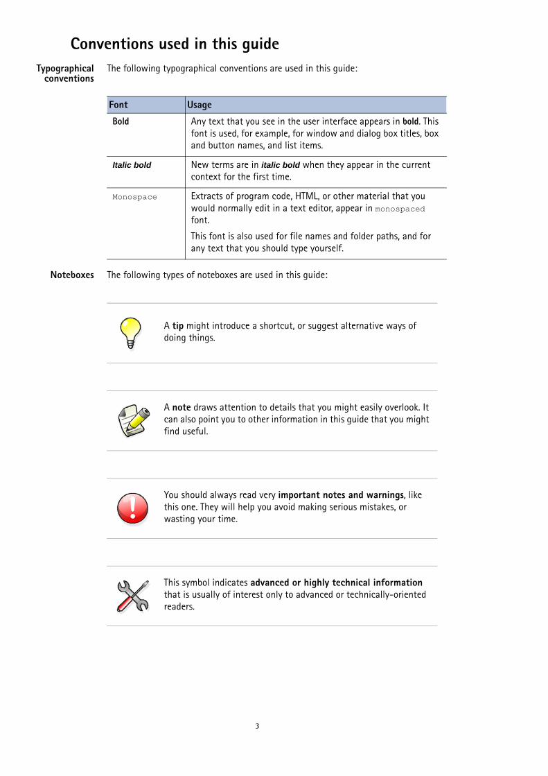
Conventions used in this guideTypographical
conventionsThe following typographical conventions are used in this guide:
Noteboxes The following types of noteboxes are used in this guide:
Font Usage
Bold Any text that you see in the user interface appears in bold. This font is used, for example, for window and dialog box titles, box and button names, and list items.
Italic bold New terms are in italic bold when they appear in the current context for the first time.
Monospace Extracts of program code, HTML, or other material that you would normally edit in a text editor, appear in monospaced font.
This font is also used for file names and folder paths, and for any text that you should type yourself.
A tip might introduce a shortcut, or suggest alternative ways of doing things.
A note draws attention to details that you might easily overlook. It can also point you to other information in this guide that you might find useful.
You should always read very important notes and warnings, like this one. They will help you avoid making serious mistakes, or wasting your time.
This symbol indicates advanced or highly technical information that is usually of interest only to advanced or technically-oriented readers.
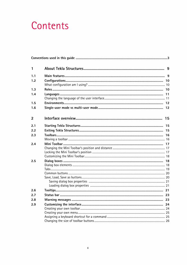
Contents
4
Conventions used in this guide ..............................................................................................................3
1 About Tekla Structures.................................................................................. 9
1.1 Main features ........................................................................................................................ 91.2 Configurations..................................................................................................................... 10
What configuration am I using? ............................................................................................................. 101.3 Roles ..................................................................................................................................... 101.4 Languages ............................................................................................................................ 11
Changing the language of the user interface...................................................................................... 111.5 Environments....................................................................................................................... 121.6 Single-user mode vs multi-user mode.............................................................................. 12
2 Interface overview........................................................................................ 15
2.1 Starting Tekla Structures................................................................................................... 152.2 Exiting Tekla Structures..................................................................................................... 152.3 Toolbars................................................................................................................................ 16
Moving a toolbar ......................................................................................................................................... 162.4 Mini Toolbar ........................................................................................................................ 17
Changing the Mini Toolbar’s position and distance .......................................................................... 17Locking the Mini Toolbar’s position ....................................................................................................... 17Customizing the Mini Toolbar.................................................................................................................. 18
2.5 Dialog boxes ........................................................................................................................ 18Dialog box elements ................................................................................................................................... 18Tabs.................................................................................................................................................................. 19Common buttons ......................................................................................................................................... 20Save, Load, Save as buttons...................................................................................................................... 20
Saving dialog box properties ............................................................................................................ 21Loading dialog box properties .......................................................................................................... 21
2.6 Tooltips................................................................................................................................. 212.7 Status bar ............................................................................................................................ 232.8 Warning messages .............................................................................................................. 232.9 Customizing the interface.................................................................................................. 24
Creating your own toolbar........................................................................................................................ 24Creating your own menu........................................................................................................................... 25Assigning a keyboard shortcut for a command .................................................................................. 25Changing the size of toolbar buttons .................................................................................................... 26
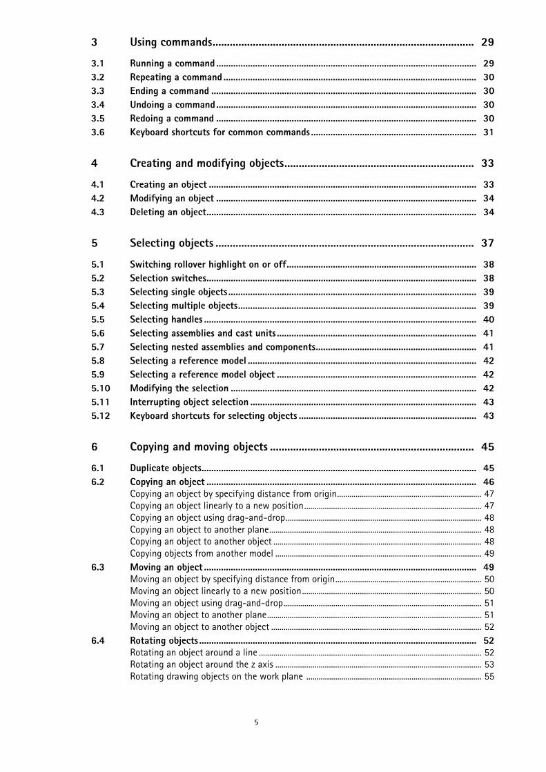
5
3 Using commands........................................................................................... 29
3.1 Running a command ........................................................................................................... 293.2 Repeating a command ........................................................................................................ 303.3 Ending a command ............................................................................................................. 303.4 Undoing a command........................................................................................................... 303.5 Redoing a command ........................................................................................................... 303.6 Keyboard shortcuts for common commands .................................................................... 31
4 Creating and modifying objects.................................................................. 33
4.1 Creating an object .............................................................................................................. 334.2 Modifying an object ........................................................................................................... 344.3 Deleting an object............................................................................................................... 34
5 Selecting objects .......................................................................................... 37
5.1 Switching rollover highlight on or off.............................................................................. 385.2 Selection switches............................................................................................................... 385.3 Selecting single objects...................................................................................................... 395.4 Selecting multiple objects.................................................................................................. 395.5 Selecting handles ................................................................................................................ 405.6 Selecting assemblies and cast units .................................................................................. 415.7 Selecting nested assemblies and components.................................................................. 415.8 Selecting a reference model .............................................................................................. 425.9 Selecting a reference model object .................................................................................. 425.10 Modifying the selection ..................................................................................................... 425.11 Interrupting object selection ............................................................................................. 435.12 Keyboard shortcuts for selecting objects ......................................................................... 43
6 Copying and moving objects ....................................................................... 45
6.1 Duplicate objects................................................................................................................. 456.2 Copying an object ............................................................................................................... 46
Copying an object by specifying distance from origin...................................................................... 47Copying an object linearly to a new position...................................................................................... 47Copying an object using drag-and-drop............................................................................................... 48Copying an object to another plane....................................................................................................... 48Copying an object to another object ..................................................................................................... 48Copying objects from another model .................................................................................................... 49
6.3 Moving an object ................................................................................................................ 49Moving an object by specifying distance from origin....................................................................... 50Moving an object linearly to a new position....................................................................................... 50Moving an object using drag-and-drop................................................................................................ 51Moving an object to another plane........................................................................................................ 51Moving an object to another object ...................................................................................................... 52
6.4 Rotating objects .................................................................................................................. 52Rotating an object around a line ............................................................................................................ 52Rotating an object around the z axis .................................................................................................... 53Rotating drawing objects on the work plane ..................................................................................... 55
6
6.5 Mirroring an object ............................................................................................................ 556.6 Keyboard shortcuts for copying and moving objects ...................................................... 56
7 Snapping to positions .................................................................................. 57
7.1 Snap zone............................................................................................................................. 587.2 Snap depth........................................................................................................................... 587.3 Snap switches ...................................................................................................................... 58
Main snap switches..................................................................................................................................... 59Other snap switches.................................................................................................................................... 60Overriding the current snap switch........................................................................................................ 61
7.4 Snapping in orthogonal directions.................................................................................... 61Snapping relative to previously picked points..................................................................................... 62
7.5 Snapping to a line............................................................................................................... 627.6 Snapping to extension lines............................................................................................... 637.7 Creating a temporary reference point .............................................................................. 657.8 Locking a coordinate .......................................................................................................... 667.9 Snapping to a position using coordinates ........................................................................ 66
Tracking .......................................................................................................................................................... 67Options for entering coordinates ............................................................................................................ 68Example: Placing a drawing object at a specified distance ............................................................ 69
7.10 Defining a snap grid ........................................................................................................... 707.11 Keyboard shortcuts for snapping ...................................................................................... 71
8 Filtering objects............................................................................................ 73
8.1 Filtering objects using a view filter .................................................................................. 73Creating a view filter.................................................................................................................................. 73
8.2 Filtering objects using a selection filter........................................................................... 74Creating a selection filter.......................................................................................................................... 75
8.3 Filtering in drawings........................................................................................................... 75Creating drawing filters............................................................................................................................. 76Creating view filters in drawings ............................................................................................................ 76
8.4 Filtering examples............................................................................................................... 77Filtering beams and columns ................................................................................................................... 78Filtering parts in specific phases............................................................................................................. 78Filtering out parts that have a certain profile..................................................................................... 79Filtering assemblies and cast units......................................................................................................... 79Filtering sub-assemblies ............................................................................................................................ 79Filtering out reference models................................................................................................................. 80Filtering reference model object properties......................................................................................... 80
8.5 Possible values in filtering ................................................................................................. 81Wildcards ....................................................................................................................................................... 81Template attributes in filtering ............................................................................................................... 82
8.6 Copying a filter to another model .................................................................................... 828.7 Deleting a filter................................................................................................................... 83
9 Tips for basic tasks....................................................................................... 85
9.1 Modifying one property in several parts at the same time............................................ 859.2 Copying and moving efficiently......................................................................................... 85

7
9.3 Selecting values from the model ...................................................................................... 869.4 Copying Mini Toolbar settings to another computer...................................................... 86

8
Main featuresAbout Tekla Structures 9
1 About Tekla Structures
Tekla Structures is a tool for structural engineers, detailers, and fabricators. It is an integrated model-based 3D solution for managing multi-material databases (steel, concrete, timber, etc.). Tekla Structures features interactive modeling, structural analysis and design, and automatic drawing creation.
You can automatically produce drawings and reports from the 3D model, at any time. Drawings and reports react to modifications in the model, and are always up to date.
Tekla Structures includes a wide range of standard drawing and report templates. You can also create your own templates using the Template Editor.
Tekla Structures supports multiple users working on the same project. You and your partners can work together on the same model, at the same time, even in different locations. This increases accuracy and quality, because you always use the most up-to-date information.
See also Main features (9)
Configurations (10)
Roles (10)
Languages (11)
Environments (12)
Single-user mode vs multi-user mode (12)
1.1 Main featuresTekla Structures includes the following features:
• Easy modeling of basic objects, such as beams, columns, and slabs.
• Useful modeling aids, such as 3D grids and an adjustable work area.• Catalogs of available material grades, profiles, bolts, and reinforcements.
• Modeling tools to create complex structures, such as staircases and trusses.
• Intelligent connections, such as end plates and clip angles, to automatically connect main members.
• A custom component editor that you can use to create your own parametric connections, details, and parts.
• Links to transfer data between Tekla Structures and other software, such as AutoCAD, STAAD, and MicroStation.
• Drawing tools to create several drawings with one click.• Data output for CNC machines.
ConfigurationsAbout Tekla Structures 10
• Capability to undo and redo changes you have made, so that you can test solutions, and revert to the original if needed.
• Tekla Structures is available in a wide range of languages, and adapted to local standards and requirements.
See also Interface overview (15)
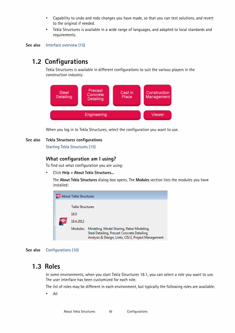
1.2 ConfigurationsTekla Structures is available in different configurations to suit the various players in the construction industry:
When you log in to Tekla Structures, select the configuration you want to use.
See also Tekla Structures configurations
Starting Tekla Structures (15)
What configuration am I using?To find out what configuration you are using:
• Click Help > About Tekla Structures...
The About Tekla Structures dialog box opens. The Modules section lists the modules you have installed:
See also Configurations (10)
1.3 RolesIn some environments, when you start Tekla Structures 18.1, you can select a role you want to use. The user interface has been customized for each role.
The list of roles may be different in each environment, but typically the following roles are available:
• All
LanguagesAbout Tekla Structures 11
• Contractor
• Engineer
• Multimaterial Detailer
• Precast Concrete Detailer• Cast in Place Detailer
• Steel Detailer
All is a combination of all roles. Multimaterial Detailer combines the roles of Precast Concrete Detailer and Steel Detailer.
See also Environments (12)
Starting Tekla Structures (15)
1.4 LanguagesWhen you install Tekla Structures, you can choose the languages you want to use. The default language for the user interface is the language in which in which you installed Tekla Structures.
Tekla Structures 18.1 software is available in the following languages:
• Chinese – simplified (chs)• Chinese – traditional (cht)
• Czech (csy)
• Dutch (nld)• English (enu)
• French (fra)
• German (deu)• Hungarian (hun)
• Italian (ita)
• Japanese (jpn)• Polish (plk)
• Portuguese (ptg)
• Portuguese – Brazilian (ptb)• Russian (rus)
• Spanish (esp)
Some language-dependent file and folder names include the abbreviations listed above.
See also Changing the language of the user interface (11)
Changing the language of the user interfaceYou can change the language of the Tekla Structures user interface at any time. The languages you can switch between are the languages you chose when you installed Tekla Structures.
To change the language of the user interface:
1. Click Tools > Change Language...2. Select a language from the Language list box.3. Click OK.4. Restart Tekla Structures for the change to take effect.
See also Languages (11)
EnvironmentsAbout Tekla Structures 12
1.5 EnvironmentsThe environment means region-specific settings and information. It defines which profiles, material grades, default values, connections, wizards, variables, reports, and templates you use.
When you install Tekla Structures, you can choose the environments you want to use. The environments available in Tekla Structures 18.1 are:
• Default environment• Australasia
• Austria
• Brazil• China
• Czech
• Finland• France
• Germany
• Greece• Hungary
• India
• Italy• Japan
• Korea
• Middle-East• Netherlands
• Netherlands (English)
• Norway• Poland
• Portugal
• Russia• South Africa
• South America
• South-East Asia• Spain
• Sweden
• Switzerland (French)
• Switzerland (German)• Switzerland (Italian)
• Taiwan
• United Kingdom• United States (Imperial)
• United States (Metric)
See also Location of environment files
1.6 Single-user mode vs multi-user modeTekla Structures can be used in either single-user or multi-user mode.
Single-user mode vs multi-user modeAbout Tekla Structures 13
When one user at a time is to work with a model, Tekla Structures should be run in single-user mode. In single-user mode, only one user can work with each model at any time.
If several users will work with a model simultaneously, you can choose to run Tekla Structures in multi-user mode. We recommend that you only run Tekla Structures in multi-user mode if the users will make use of the additional features of multi-user mode.
To run Tekla Structures in multi-user mode, one machine in the network has to be set up as a server running the Tekla Structures server program.
See also Multi-user mode

Single-user mode vs multi-user modeAbout Tekla Structures 14
Starting Tekla StructuresInterface overview 15
2 Interface overview
This section provides an overview of the Tekla Structures user interface and its basic features.
See also Starting Tekla Structures (15)
Exiting Tekla Structures (15)
Toolbars (16)
Mini Toolbar (17)
Dialog boxes (18)
Tooltips (21)
Status bar (23)
Warning messages (23)
Customizing the interface (24)
2.1 Starting Tekla StructuresOnce you have installed Tekla Structures you are ready to start using it.
To start Tekla Structures:
1. Click the Windows Start button.2. Click All Programs.3. Go to the Tekla Structures 18.1 menu item and click the Tekla Structures icon.4. Wait for the login dialog box to appear.5. Select the environment, role, and configuration you want to use.6. Click OK.
See also Environments (12)
Roles (10)
Configurations (10)
2.2 Exiting Tekla StructuresTo exit Tekla Structures, do one of the following:
• Click the Close button in the upper-right corner of the Tekla Structures window.• Click File > Exit.
A confirmation dialog box appears and you can choose whether or not to save the model.
ToolbarsInterface overview 16
See also Saving a model
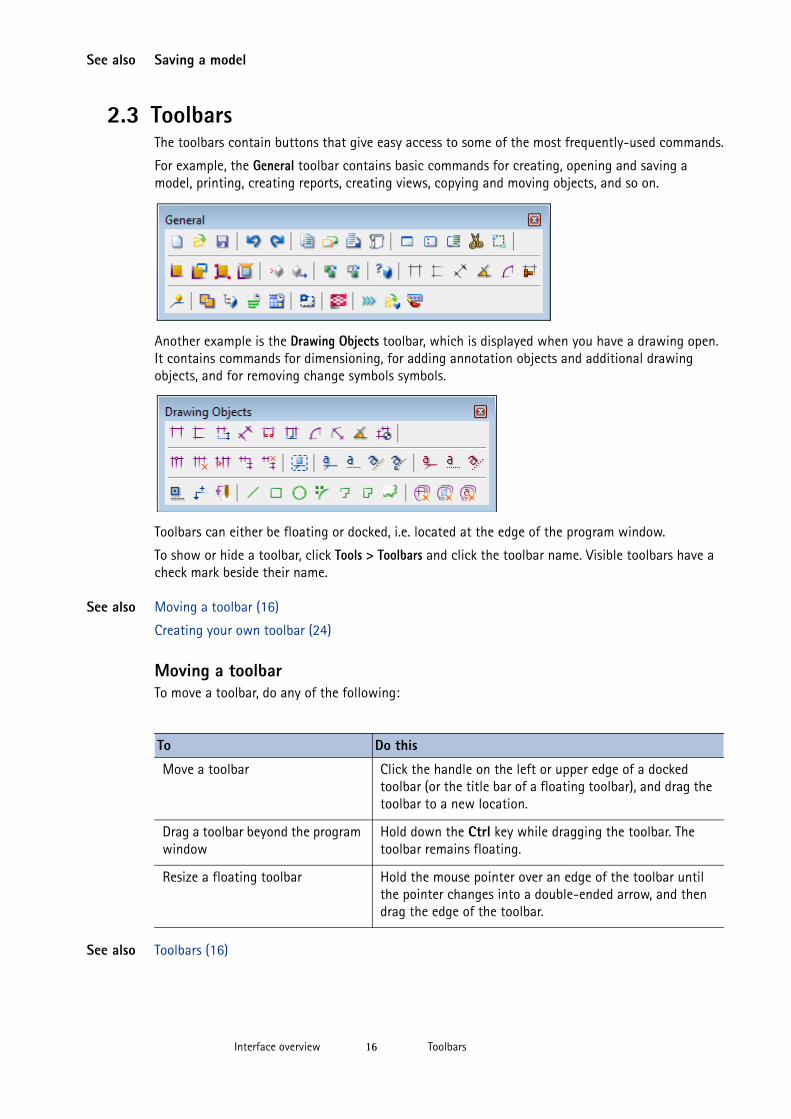
2.3 ToolbarsThe toolbars contain buttons that give easy access to some of the most frequently-used commands.
For example, the General toolbar contains basic commands for creating, opening and saving a model, printing, creating reports, creating views, copying and moving objects, and so on.
Another example is the Drawing Objects toolbar, which is displayed when you have a drawing open. It contains commands for dimensioning, for adding annotation objects and additional drawing objects, and for removing change symbols symbols.
Toolbars can either be floating or docked, i.e. located at the edge of the program window.
To show or hide a toolbar, click Tools > Toolbars and click the toolbar name. Visible toolbars have a check mark beside their name.
See also Moving a toolbar (16)
Creating your own toolbar (24)
Moving a toolbarTo move a toolbar, do any of the following:
See also Toolbars (16)
To Do this
Move a toolbar Click the handle on the left or upper edge of a docked toolbar (or the title bar of a floating toolbar), and drag the toolbar to a new location.
Drag a toolbar beyond the program window
Hold down the Ctrl key while dragging the toolbar. The toolbar remains floating.
Resize a floating toolbar Hold the mouse pointer over an edge of the toolbar until the pointer changes into a double-ended arrow, and then drag the edge of the toolbar.
Mini ToolbarInterface overview 17
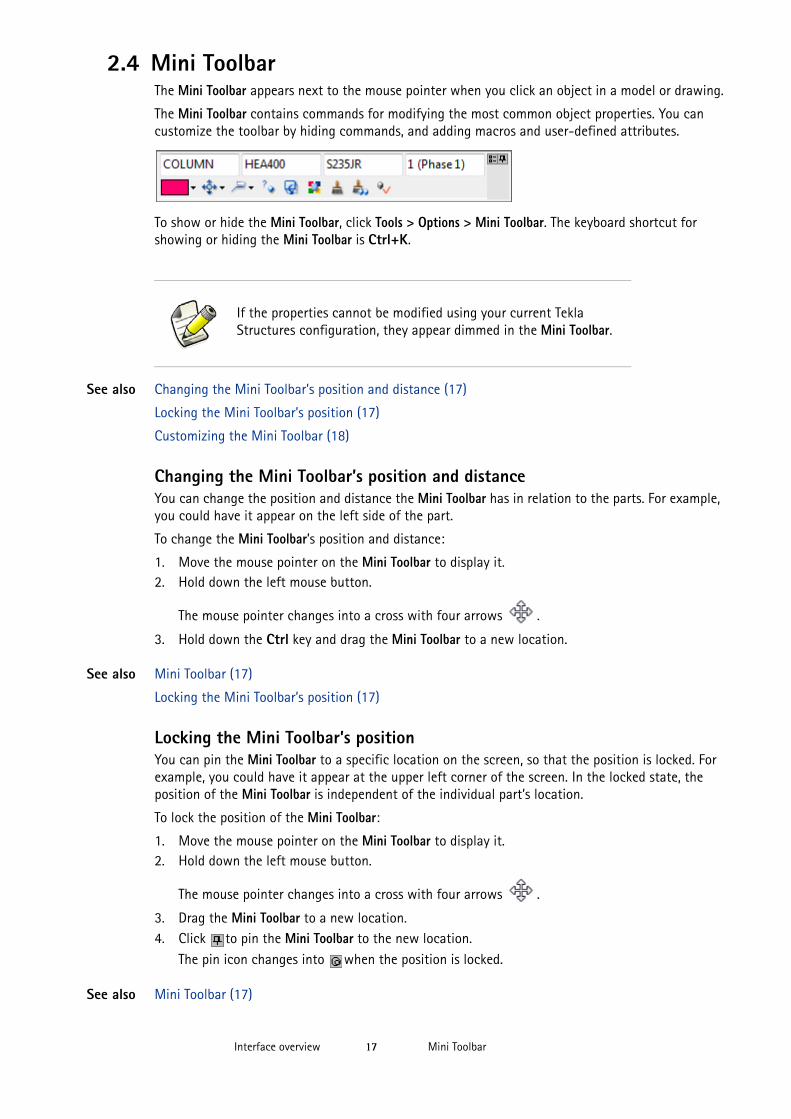
2.4 Mini ToolbarThe Mini Toolbar appears next to the mouse pointer when you click an object in a model or drawing.
The Mini Toolbar contains commands for modifying the most common object properties. You can customize the toolbar by hiding commands, and adding macros and user-defined attributes.
To show or hide the Mini Toolbar, click Tools > Options > Mini Toolbar. The keyboard shortcut for showing or hiding the Mini Toolbar is Ctrl+K.
See also Changing the Mini Toolbar’s position and distance (17)
Locking the Mini Toolbar’s position (17)
Customizing the Mini Toolbar (18)
Changing the Mini Toolbar’s position and distanceYou can change the position and distance the Mini Toolbar has in relation to the parts. For example, you could have it appear on the left side of the part.
To change the Mini Toolbar’s position and distance:
1. Move the mouse pointer on the Mini Toolbar to display it.2. Hold down the left mouse button.
The mouse pointer changes into a cross with four arrows .
3. Hold down the Ctrl key and drag the Mini Toolbar to a new location.
See also Mini Toolbar (17)
Locking the Mini Toolbar’s position (17)
Locking the Mini Toolbar’s positionYou can pin the Mini Toolbar to a specific location on the screen, so that the position is locked. For example, you could have it appear at the upper left corner of the screen. In the locked state, the position of the Mini Toolbar is independent of the individual part’s location.
To lock the position of the Mini Toolbar:
1. Move the mouse pointer on the Mini Toolbar to display it.2. Hold down the left mouse button.
The mouse pointer changes into a cross with four arrows .
3. Drag the Mini Toolbar to a new location.4. Click to pin the Mini Toolbar to the new location.
The pin icon changes into when the position is locked.
See also Mini Toolbar (17)
If the properties cannot be modified using your current Tekla Structures configuration, they appear dimmed in the Mini Toolbar.
Dialog boxesInterface overview 18
Changing the Mini Toolbar’s position and distance (17)
Customizing the Mini ToolbarYou can customize the Mini Toolbar by selecting which commands are visible, and by adding macros and user-defined attributes to the toolbar.
To customize the Mini Toolbar:
1. Move the mouse pointer on the Mini Toolbar to display it.
2. Click to open the Customize Mini Toolbar dialog box.3. Select the elements you wish to show or hide.
The Preview field shows what the toolbar will look like.
4. Include macros and user-defined attributes in the Mini Toolbar.a Select a macro or user-defined attribute in the list of macros and user-defined
attributes.
b Click Add to Mini Toolbar after each selected macro and user-defined attribute.The added macros and user-defined attributes are shown in the list of visible elements.
c To remove macros and user-defined attributes from the Mini Toolbar, clear the check boxes next to them in the list of visible elements.
5. Click OK.
See also Mini Toolbar (17)
Changing user-defined fields
Adding properties
2.5 Dialog boxesYou can use dialog boxes to modify object properties. If you click any command or a button that has three dots in its name, for example Select..., Tekla Structures displays the appropriate dialog box.
See also Dialog box elements (18)
Tabs (19)
Common buttons (20)
Save, Load, Save as buttons (20)
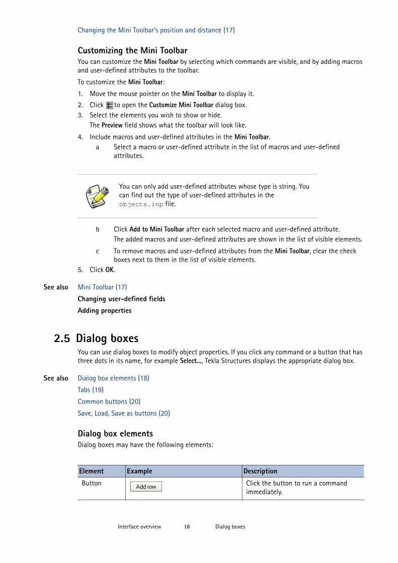
Dialog box elementsDialog boxes may have the following elements:
You can only add user-defined attributes whose type is string. You can find out the type of user-defined attributes in the objects.inp file.
Element Example Description
Button Click the button to run a command immediately.
Dialog boxesInterface overview 19
See also Common buttons (20)
Save, Load, Save as buttons (20)
Tabs (19)
TabsInformation in some Tekla Structures dialog boxes has been divided up on several tabs. This makes the dialog boxes easier to use. Moving from tab to tab does not affect the information they contain.
The common buttons located at the top and bottom of a dialog box affect all the tabs in the dialog box. For example, when you click Save before closing the dialog box, Tekla Structures saves all information on all tabs to the designated file.
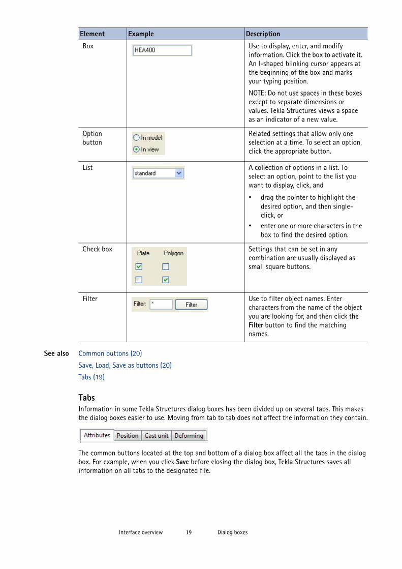
Box Use to display, enter, and modify information. Click the box to activate it. An I-shaped blinking cursor appears at the beginning of the box and marks your typing position.
NOTE: Do not use spaces in these boxes except to separate dimensions or values. Tekla Structures views a space as an indicator of a new value.
Option button
Related settings that allow only one selection at a time. To select an option, click the appropriate button.
List A collection of options in a list. To select an option, point to the list you want to display, click, and
• drag the pointer to highlight the desired option, and then single-click, or
• enter one or more characters in the box to find the desired option.
Check box Settings that can be set in any combination are usually displayed as small square buttons.
Filter Use to filter object names. Enter characters from the name of the object you are looking for, and then click the Filter button to find the matching names.
Element Example Description
Dialog boxesInterface overview 20
See also Common buttons (20)
Save, Load, Save as buttons (20)
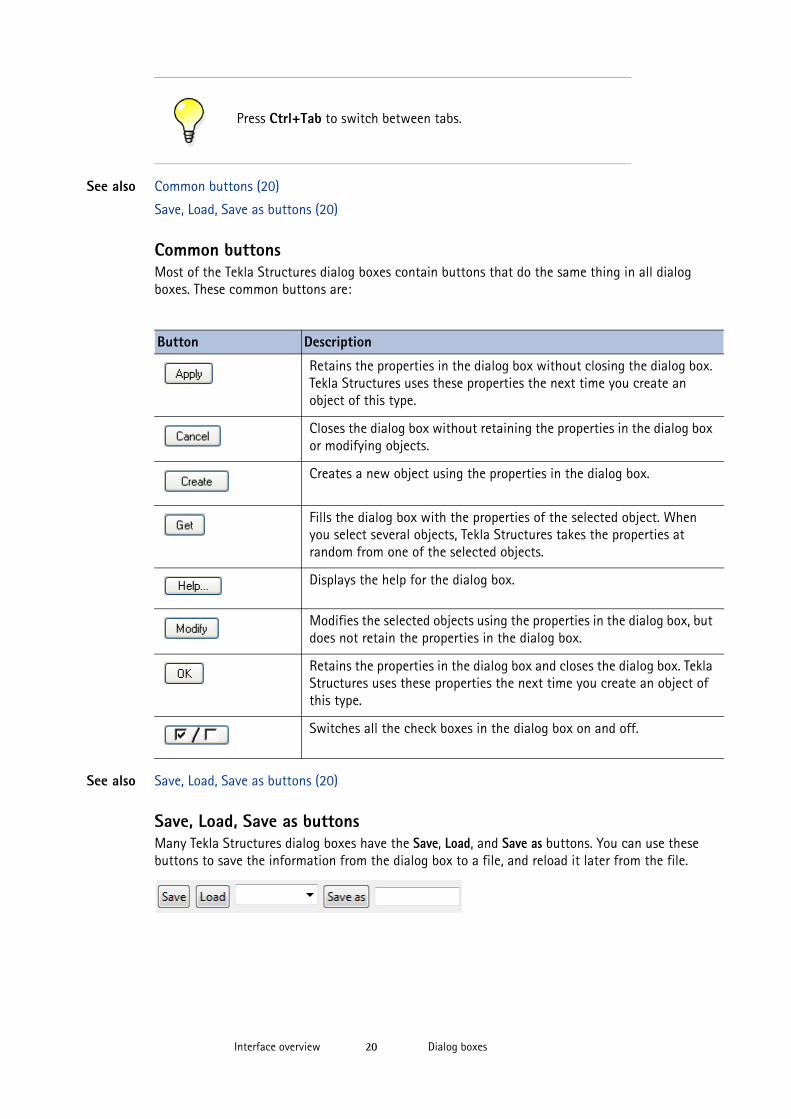
Common buttonsMost of the Tekla Structures dialog boxes contain buttons that do the same thing in all dialog boxes. These common buttons are:
See also Save, Load, Save as buttons (20)
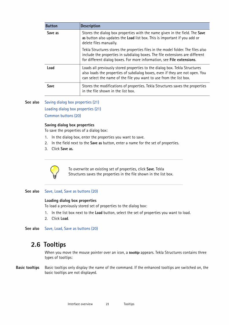
Save, Load, Save as buttonsMany Tekla Structures dialog boxes have the Save, Load, and Save as buttons. You can use these buttons to save the information from the dialog box to a file, and reload it later from the file.
Press Ctrl+Tab to switch between tabs.
Button Description
Retains the properties in the dialog box without closing the dialog box. Tekla Structures uses these properties the next time you create an object of this type.
Closes the dialog box without retaining the properties in the dialog box or modifying objects.
Creates a new object using the properties in the dialog box.
Fills the dialog box with the properties of the selected object. When you select several objects, Tekla Structures takes the properties at random from one of the selected objects.
Displays the help for the dialog box.
Modifies the selected objects using the properties in the dialog box, but does not retain the properties in the dialog box.
Retains the properties in the dialog box and closes the dialog box. Tekla Structures uses these properties the next time you create an object of this type.
Switches all the check boxes in the dialog box on and off.
TooltipsInterface overview 21
See also Saving dialog box properties (21)
Loading dialog box properties (21)
Common buttons (20)
Saving dialog box propertiesTo save the properties of a dialog box:
1. In the dialog box, enter the properties you want to save.2. In the field next to the Save as button, enter a name for the set of properties.3. Click Save as.
See also Save, Load, Save as buttons (20)
Loading dialog box propertiesTo load a previously stored set of properties to the dialog box:
1. In the list box next to the Load button, select the set of properties you want to load.2. Click Load.
See also Save, Load, Save as buttons (20)
2.6 TooltipsWhen you move the mouse pointer over an icon, a tooltip appears. Tekla Structures contains three types of tooltips:
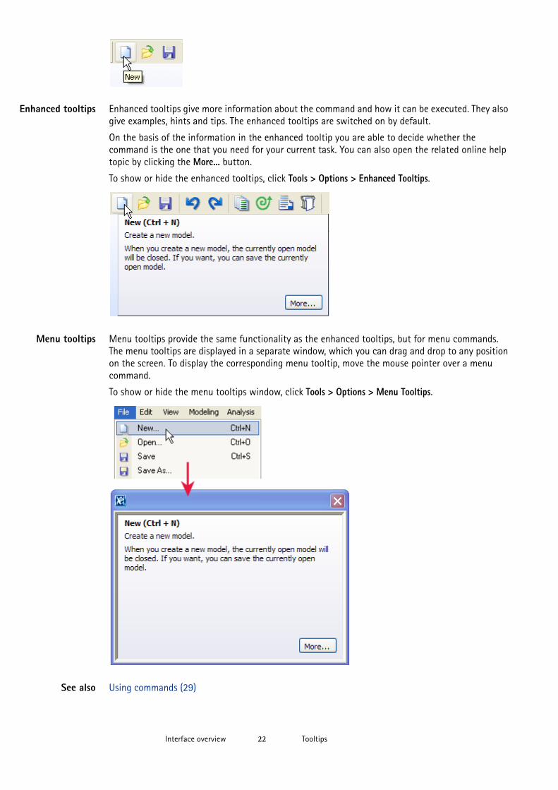
Basic tooltips Basic tooltips only display the name of the command. If the enhanced tooltips are switched on, the basic tooltips are not displayed.
Button Description
Save as Stores the dialog box properties with the name given in the field. The Save as button also updates the Load list box. This is important if you add or delete files manually.
Tekla Structures stores the properties files in the model folder. The files also include the properties in subdialog boxes. The file extensions are different for different dialog boxes. For more information, see File extensions.
Load Loads all previously stored properties to the dialog box. Tekla Structures also loads the properties of subdialog boxes, even if they are not open. You can select the name of the file you want to use from the list box.
Save Stores the modifications of properties. Tekla Structures saves the properties in the file shown in the list box.
To overwrite an existing set of properties, click Save. Tekla Structures saves the properties in the file shown in the list box.
TooltipsInterface overview 22
Enhanced tooltips Enhanced tooltips give more information about the command and how it can be executed. They also give examples, hints and tips. The enhanced tooltips are switched on by default.
On the basis of the information in the enhanced tooltip you are able to decide whether the command is the one that you need for your current task. You can also open the related online help topic by clicking the More... button.
To show or hide the enhanced tooltips, click Tools > Options > Enhanced Tooltips.
Menu tooltips Menu tooltips provide the same functionality as the enhanced tooltips, but for menu commands. The menu tooltips are displayed in a separate window, which you can drag and drop to any position on the screen. To display the corresponding menu tooltip, move the mouse pointer over a menu command.
To show or hide the menu tooltips window, click Tools > Options > Menu Tooltips.
See also Using commands (29)
Status barInterface overview 23
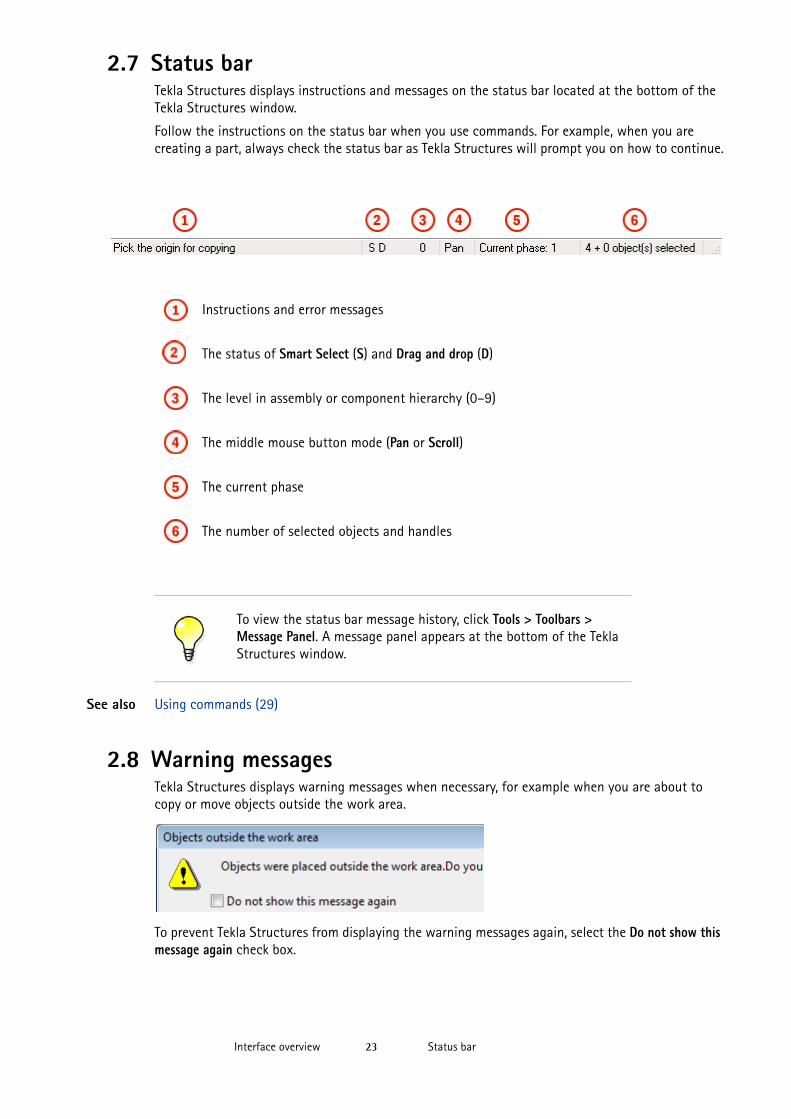
2.7 Status barTekla Structures displays instructions and messages on the status bar located at the bottom of the Tekla Structures window.
Follow the instructions on the status bar when you use commands. For example, when you are creating a part, always check the status bar as Tekla Structures will prompt you on how to continue.
See also Using commands (29)
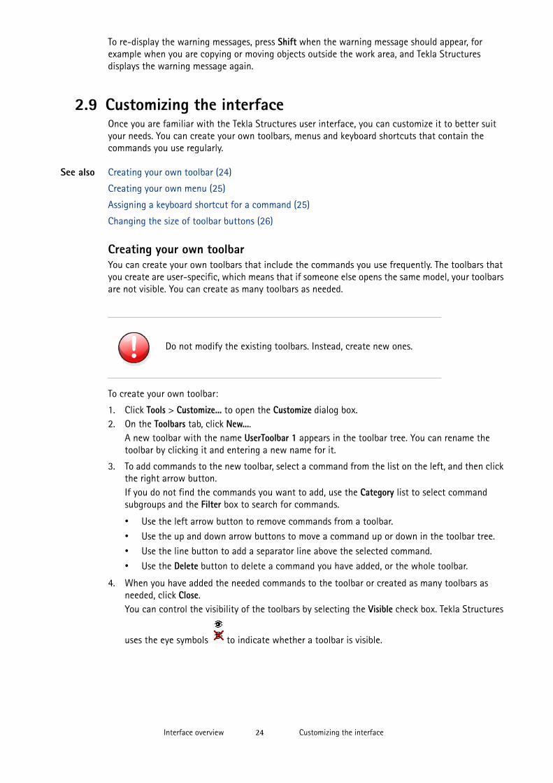
2.8 Warning messagesTekla Structures displays warning messages when necessary, for example when you are about to copy or move objects outside the work area.
To prevent Tekla Structures from displaying the warning messages again, select the Do not show this message again check box.
Instructions and error messages
The status of Smart Select (S) and Drag and drop (D)
The level in assembly or component hierarchy (0–9)
The middle mouse button mode (Pan or Scroll)
The current phase
The number of selected objects and handles
To view the status bar message history, click Tools > Toolbars > Message Panel. A message panel appears at the bottom of the Tekla Structures window.
Customizing the interfaceInterface overview 24
To re-display the warning messages, press Shift when the warning message should appear, for example when you are copying or moving objects outside the work area, and Tekla Structures displays the warning message again.
2.9 Customizing the interfaceOnce you are familiar with the Tekla Structures user interface, you can customize it to better suit your needs. You can create your own toolbars, menus and keyboard shortcuts that contain the commands you use regularly.
See also Creating your own toolbar (24)
Creating your own menu (25)
Assigning a keyboard shortcut for a command (25)
Changing the size of toolbar buttons (26)
Creating your own toolbarYou can create your own toolbars that include the commands you use frequently. The toolbars that you create are user-specific, which means that if someone else opens the same model, your toolbars are not visible. You can create as many toolbars as needed.
To create your own toolbar:
1. Click Tools > Customize... to open the Customize dialog box.2. On the Toolbars tab, click New....
A new toolbar with the name UserToolbar 1 appears in the toolbar tree. You can rename the toolbar by clicking it and entering a new name for it.
3. To add commands to the new toolbar, select a command from the list on the left, and then click the right arrow button. If you do not find the commands you want to add, use the Category list to select command subgroups and the Filter box to search for commands.
• Use the left arrow button to remove commands from a toolbar.
• Use the up and down arrow buttons to move a command up or down in the toolbar tree.• Use the line button to add a separator line above the selected command.
• Use the Delete button to delete a command you have added, or the whole toolbar.
4. When you have added the needed commands to the toolbar or created as many toolbars as needed, click Close.You can control the visibility of the toolbars by selecting the Visible check box. Tekla Structures
uses the eye symbols to indicate whether a toolbar is visible.
Do not modify the existing toolbars. Instead, create new ones.
Customizing the interfaceInterface overview 25
See also Creating your own menu (25)
Creating your own menuYou can create your own menu that contains the commands you use frequently. You can create only one custom menu, and this menu is always called User.
To create your own menu:
1. Click Tools > Customize... to open the Customize dialog box.2. Click the Menu tab.3. To add commands to the new menu, select a command from the list on the left, and then click
the right arrow button. If you do not find the commands you want to add, use the Category list to select command subgroups and the Filter box to search for commands.
Tekla Structures displays the commands on the menu on the right side of the dialog box.
• Use the left arrow button to remove commands from a menu.
• Use the up and down arrow buttons to move a command up or down in the menu tree.• Use the line button to add a separator line above the selected command.
4. When you have added the needed commands to the menu, click Close.5. Restart Tekla Structures to activate the menu.
The name of the menu is always User.
See also Creating your own toolbar (24)
Assigning a keyboard shortcut for a commandIn addition to many predefined keyboard shortcuts in Tekla Structures, you can define your own keyboard shortcuts. If you frequently use certain commands, assign keyboard shortcuts to them. Using keyboard shortcuts is faster than using the commands on toolbars and menus.
To assign a keyboard shortcut to a command:
1. Click Tools > Customize... to open the Customize dialog box.
Always create and modify drawing command toolbars in the modeling mode. If you create or modify toolbars in the drawing mode, the new toolbars and toolbar changes are not saved.
Always create and modify the User menu in the modeling mode. If you create or modify the User menu in the drawing mode, the new User menu or menu changes are not saved.
Before you can assign a keyboard shortcut to a command, you need to create a custom User menu.
Customizing the interfaceInterface overview 26
2. Select a command from the list on the left. Use the Category list to select command subgroups.
Use the Filter box to search for commands.
3. To assign a keyboard shortcut for the command, use the Shortcut boxes.You can use a single letter, or combine a letter with the Shift, Alt or Ctrl keys.
The following keys are valid in keyboard shortcuts:
• A–Z• 0–9• F1–F24• Left arrow, Right arrow, Up arrow, Down arrow• Backspace, Enter, Esc, Tab• Insert, Delete, Home, End, Page Up, Page Down• 0–9 on the numeric keypad
• * (Multiply), / (Divide), + (Add), - (Subtract), , (Decimal) on the numeric keypad
4. To activate the new keyboard shortcut, add the command to the custom User menu.5. Click Close.
See also Creating your own menu (25)
Keyboard shortcuts for common commands (31)
Keyboard shortcuts for viewing the model
Keyboard shortcuts for selecting objects (43)
Keyboard shortcuts for copying and moving objects (56)
Keyboard shortcuts for snapping (71)
Keyboard shortcuts for checking the model
Keyboard shortcuts for part representation options
Keyboard shortcuts for component representation options
Keyboard shortcuts for drawings
Keyboard shortcuts for UCS
Changing the size of toolbar buttonsBy default, the size of the buttons on the toolbars is 16x16 pixels. If the buttons look too small, you can change their size to 24x24 pixels.
To change the size of toolbar buttons:
1. Click Tools > Customize... to open the Customize dialog box.
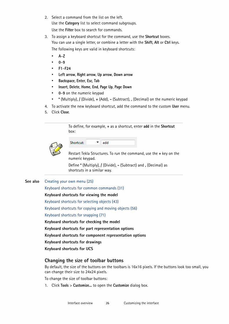
To define, for example, + as a shortcut, enter add in the Shortcut box:
Restart Tekla Structures. To run the command, use the + key on the numeric keypad.
Define * (Multiply), / (Divide), - (Subtract) and , (Decimal) as shortcuts in a similar way.
Customizing the interfaceInterface overview 27
2. Select the Large icons check box.The size of the buttons changes.
3. Click Close.
See also Customizing the interface (24)
Creating your own toolbar (24)
Creating your own menu (25)

Customizing the interfaceInterface overview 28
Running a commandUsing commands 29
3 Using commands
This section explains how to run, repeat, and end commands.
You can use some Tekla Structures commands simultaneously. This means that you can use these commands while another command is still running. For example, you can use the Zoom commands while creating objects.
To get more information about a command and how it can be executed, use the enhanced tooltips and menu tooltips, and follow the instructions on the status bar.
See also Tooltips (21)
Status bar (23)
Running a command (29)
Repeating a command (30)
Ending a command (30)
Undoing a command (30)
Redoing a command (30)
Keyboard shortcuts for common commands (31)
3.1 Running a commandTo run a command in Tekla Structures, do one of the following:
• Click the toolbar button of the command you want to run.
For example, click to create bolts.
• Click a menu title and then select the command.For example, click Detailing > Bolts > Create Bolts.
• Click the right mouse button to open a pop-up menu, and then select a command. When you select an object, the commands on the pop-up menu relate to that object.
The command runs until you end it or use another command.
See also Repeating a command (30)
Ending a command (30)
Undoing a command (30)
Repeating a commandUsing commands 30
3.2 Repeating a commandTo repeat the last command, do one of the following:
• Click Edit > Repeat Last Command.• Press Enter.
See also Running a command (29)
3.3 Ending a commandTo cancel or end a command, do one of the following:
• Click Edit > Interrupt.• Right-click and select Interrupt from the pop-up menu.
• Press Esc.
See also Running a command (29)
Undoing a command (30)
3.4 Undoing a commandYou can undo commands and actions that you have previously done in Tekla Structures. You can undo all actions since the last save in the current session. Creating or opening a drawing clears the undo log.
To undo a command, do one of the following:
• Click .• Click Edit > Undo.• Press Ctrl + Z.
Limitations You cannot undo view commands.
See also Redoing a command (30)
3.5 Redoing a commandYou can redo commands and actions that were previously undone. Before you can redo anything, you must use the Undo command to reverse at least one action. You can redo all actions since the last Redo command or last save in the current session. Creating or opening a drawing clears the redo log.
To redo a command, do one of the following:
• Click .• Click Edit > Redo.• Press Ctrl + Y.
Limitations You cannot redo view commands.
See also Undoing a command (30)
Keyboard shortcuts for common commandsUsing commands 31
3.6 Keyboard shortcuts for common commands
See also Using commands (29)
Assigning a keyboard shortcut for a command (25)
Command Keyboard shortcut
Help F1
Create new model Ctrl+N
Open model Ctrl+O
Save model Ctrl+S
Delete Del
Properties Alt+Enter
Undo Ctrl+Z
Redo Ctrl+Y
Interrupt Esc
Repeat last command Enter
Show or hide Mini Toolbar Ctrl+K

Keyboard shortcuts for common commandsUsing commands 32
Creating an objectCreating and modifying objects 33
4 Creating and modifying objects
This section explains how to create and modify objects in Tekla Structures models and drawings.
As you become familiar with Tekla Structures, you will find that there are several ways to create and modify objects. This section introduces most of the ways. Later in this manual, we refer to this section or present only the ways most useful for a first-time user. After some practice, you may choose a different way.
See also Creating an object (33)
Modifying an object (34)
Deleting an object (34)
4.1 Creating an objectTo create an object:
1. Open the object properties dialog box by doing one of the following:• Double-click an existing object.
• Double-click a toolbar button.• Hold down Shift and select a menu command.
• Click in the Mini Toolbar.
For example, to display the beam properties, double-click , or hold down Shift and click Modeling > Create Steel Part > Beam.
2. If needed, modify the properties.If you do not modify the properties, Tekla Structures creates the object using the current properties of the object type.
3. Click Apply or OK.4. Pick points to place the object in the model.
To create several objects with the same properties, pick multiple points. The command runs until you end it or use another command.
When you create a new object in the model and pick the start point for it, Tekla Structures displays the dimensions and dimension lines for the object. The displayed dimensions make it easier to create objects of desired length.
Modifying an objectCreating and modifying objects 34
See also Dialog boxes (18)
Mini Toolbar (17)
Using commands (29)
4.2 Modifying an objectTo modify an object:
1. Select the objects you want to modify.2. Open the object properties dialog box by doing one of the following:
• Double-click an existing object.
• Double-click a toolbar button.• Hold down Shift and select a menu command.
• Click in the Mini Toolbar.
For example, to display the beam properties, double-click , or hold down Shift and click Modeling > Create Steel Part > Beam.
3. To indicate which properties should be changed, select or clear the desired check boxes.
4. Modify the properties.
5. Click Modify.
See also Dialog boxes (18)
Mini Toolbar (17)
Selecting objects (37)
Modifying the shape of a part
4.3 Deleting an objectTo delete an object:
1. Select the object you want to delete.2. Do one of the following:
• Click Edit > Delete.
• Right-click and select Delete from the pop-up menu..
Click to switch all check boxes on or off.
You can also modify an object by right-clicking the selected object and selecting Modify from the pop-up menu. Tekla Structures displays the handles that you can use to modify the object. Select a handle to drag it to a new location.

Deleting an objectCreating and modifying objects 35
• Press Delete.
See also Selecting objects (37)

Deleting an objectCreating and modifying objects 36
Selecting objects 37
5 Selecting objects
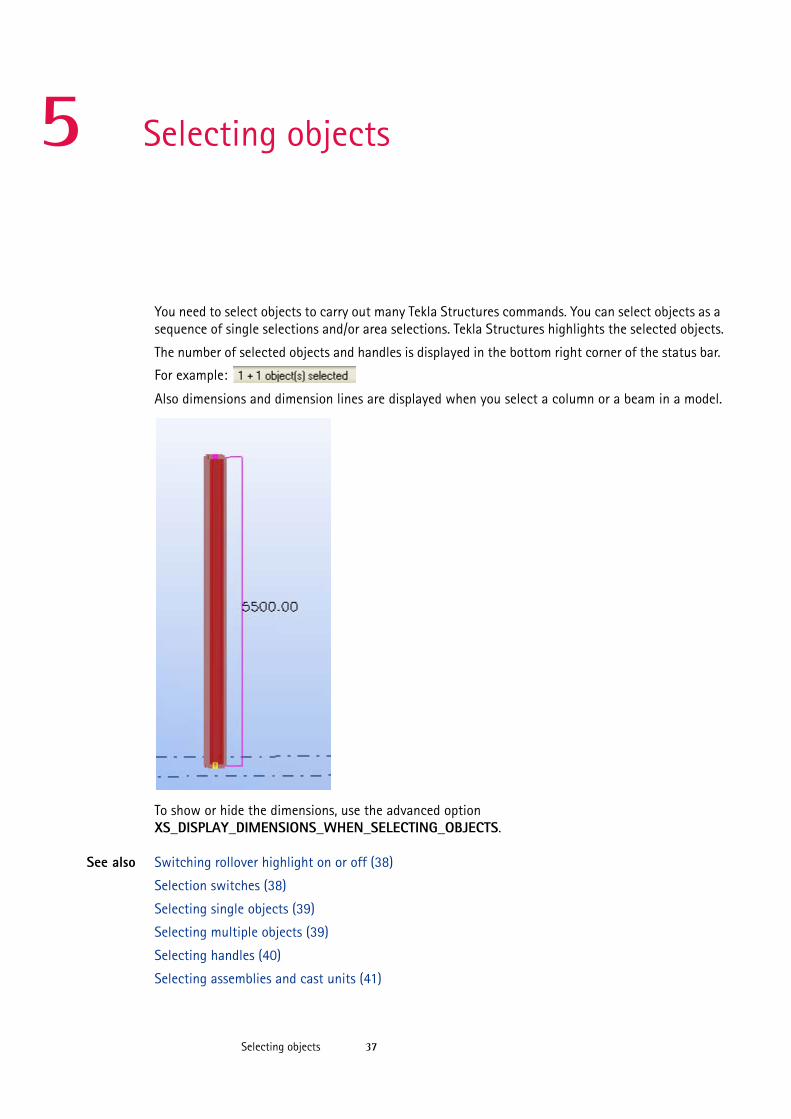
You need to select objects to carry out many Tekla Structures commands. You can select objects as a sequence of single selections and/or area selections. Tekla Structures highlights the selected objects.
The number of selected objects and handles is displayed in the bottom right corner of the status bar.
For example:
Also dimensions and dimension lines are displayed when you select a column or a beam in a model.
To show or hide the dimensions, use the advanced option XS_DISPLAY_DIMENSIONS_WHEN_SELECTING_OBJECTS.
See also Switching rollover highlight on or off (38)
Selection switches (38)
Selecting single objects (39)
Selecting multiple objects (39)
Selecting handles (40)
Selecting assemblies and cast units (41)
Switching rollover highlight on or offSelecting objects 38
Selecting nested assemblies and components (41)
Selecting a reference model (42)
Selecting a reference model object (42)
Modifying the selection (42)
Interrupting object selection (43)
Keyboard shortcuts for selecting objects (43)
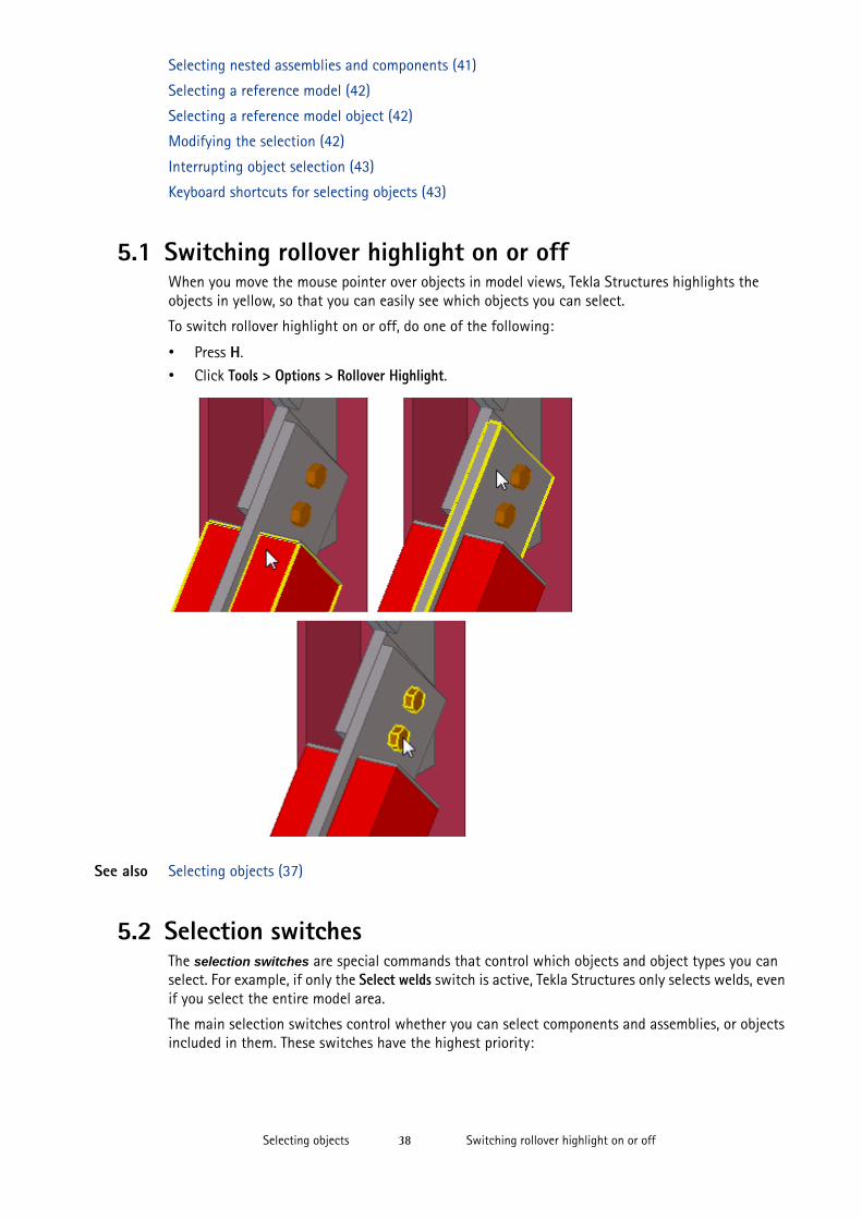
5.1 Switching rollover highlight on or offWhen you move the mouse pointer over objects in model views, Tekla Structures highlights the objects in yellow, so that you can easily see which objects you can select.
To switch rollover highlight on or off, do one of the following:
• Press H.
• Click Tools > Options > Rollover Highlight.
See also Selecting objects (37)
5.2 Selection switchesThe selection switches are special commands that control which objects and object types you can select. For example, if only the Select welds switch is active, Tekla Structures only selects welds, even if you select the entire model area.
The main selection switches control whether you can select components and assemblies, or objects included in them. These switches have the highest priority:
Selecting single objectsSelecting objects 39
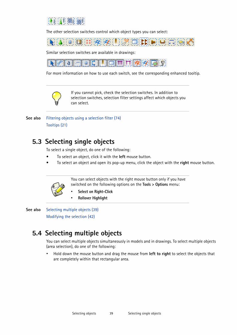
The other selection switches control which object types you can select:
Similar selection switches are available in drawings:
For more information on how to use each switch, see the corresponding enhanced tooltip.
See also Filtering objects using a selection filter (74)
Tooltips (21)
5.3 Selecting single objectsTo select a single object, do one of the following:
• To select an object, click it with the left mouse button.• To select an object and open its pop-up menu, click the object with the right mouse button.
See also Selecting multiple objects (39)
Modifying the selection (42)
5.4 Selecting multiple objectsYou can select multiple objects simultaneously in models and in drawings. To select multiple objects (area selection), do one of the following:
• Hold down the mouse button and drag the mouse from left to right to select the objects that are completely within that rectangular area.
If you cannot pick, check the selection switches. In addition to selection switches, selection filter settings affect which objects you can select.
You can select objects with the right mouse button only if you have switched on the following options on the Tools > Options menu:
• Select on Right-Click• Rollover Highlight
Selecting handlesSelecting objects 40
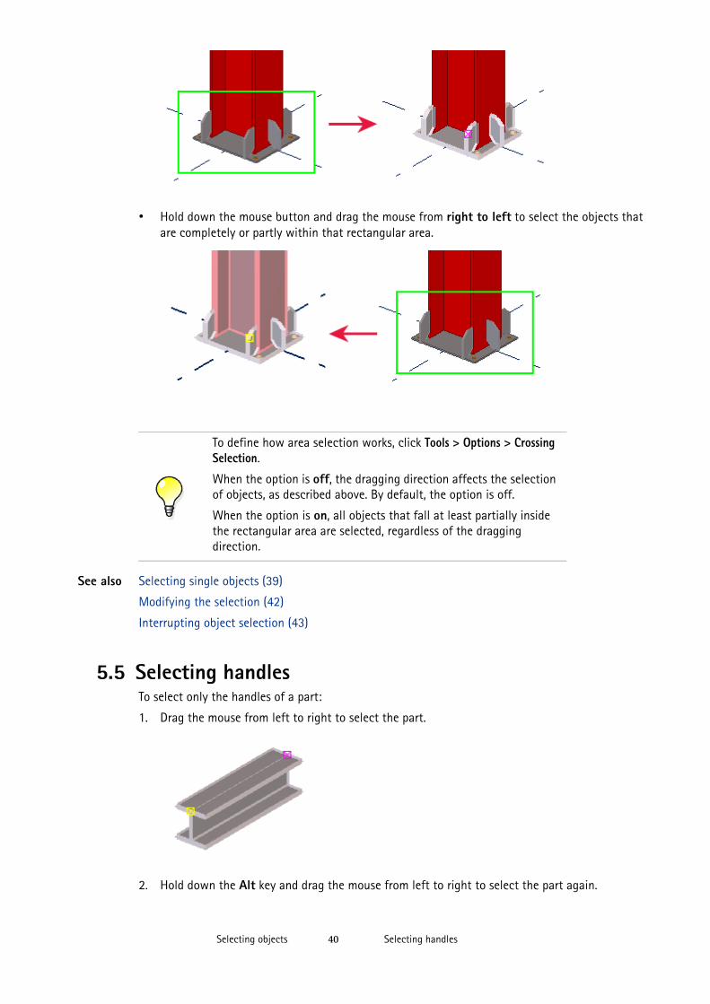
• Hold down the mouse button and drag the mouse from right to left to select the objects that are completely or partly within that rectangular area.
See also Selecting single objects (39)
Modifying the selection (42)
Interrupting object selection (43)
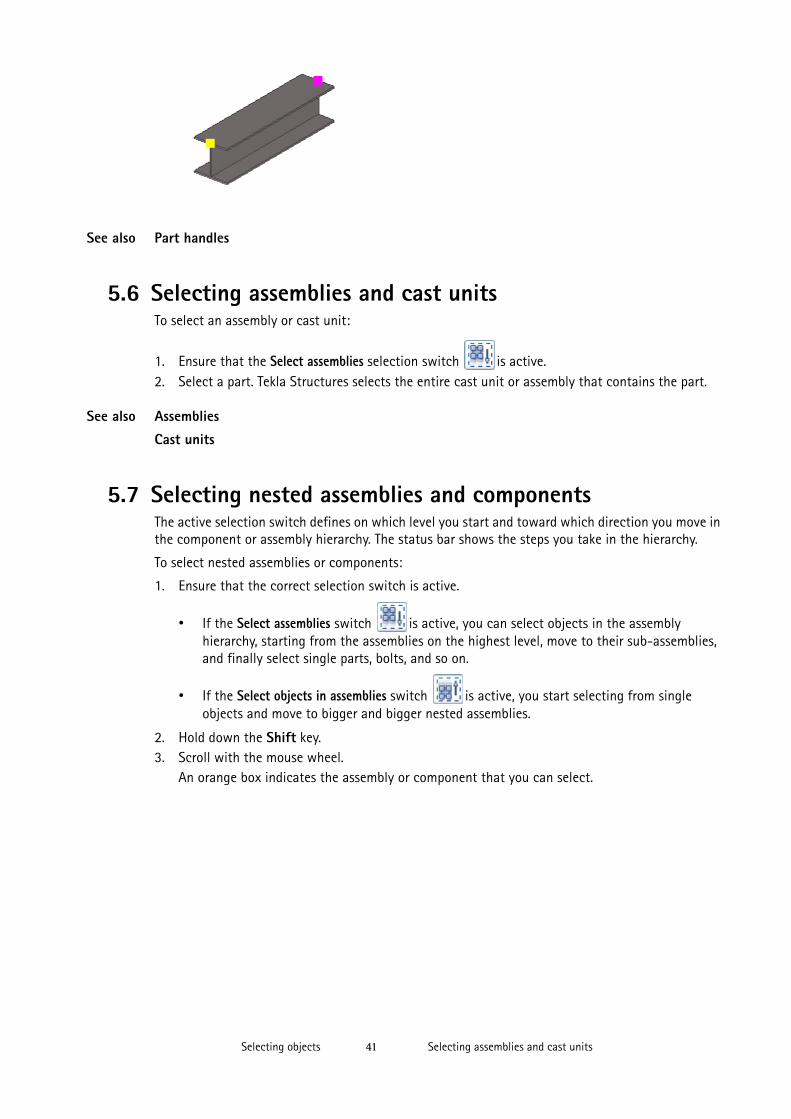
5.5 Selecting handlesTo select only the handles of a part:
1. Drag the mouse from left to right to select the part.
2. Hold down the Alt key and drag the mouse from left to right to select the part again.
To define how area selection works, click Tools > Options > Crossing Selection.
When the option is off, the dragging direction affects the selection of objects, as described above. By default, the option is off.
When the option is on, all objects that fall at least partially inside the rectangular area are selected, regardless of the dragging direction.
Selecting assemblies and cast unitsSelecting objects 41
See also Part handles
5.6 Selecting assemblies and cast unitsTo select an assembly or cast unit:
1. Ensure that the Select assemblies selection switch is active.2. Select a part. Tekla Structures selects the entire cast unit or assembly that contains the part.
See also Assemblies
Cast units
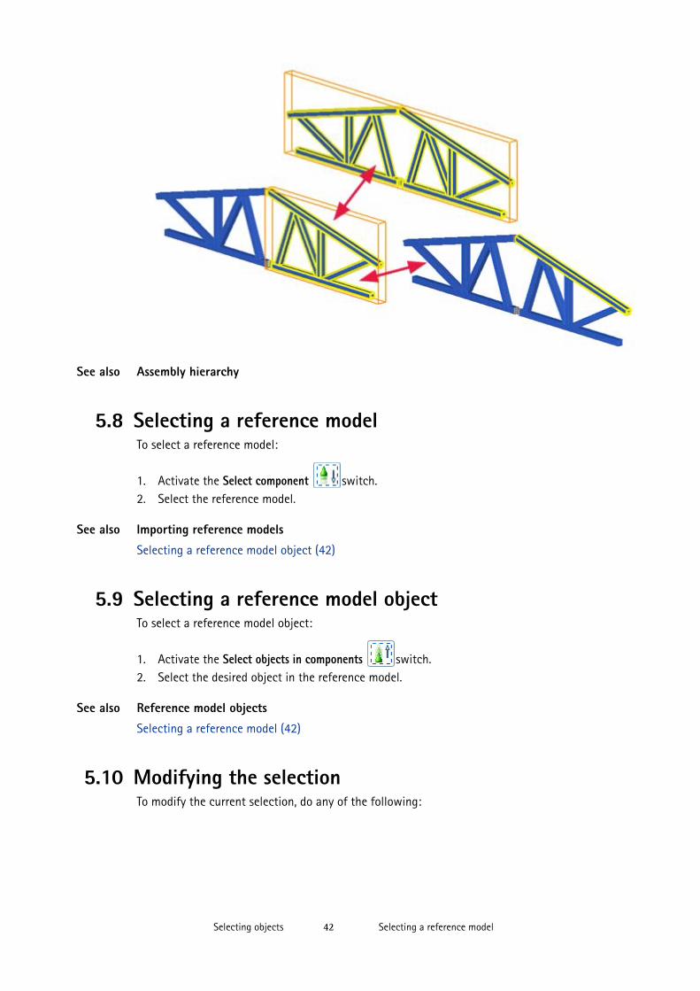
5.7 Selecting nested assemblies and componentsThe active selection switch defines on which level you start and toward which direction you move in the component or assembly hierarchy. The status bar shows the steps you take in the hierarchy.
To select nested assemblies or components:
1. Ensure that the correct selection switch is active.
• If the Select assemblies switch is active, you can select objects in the assembly hierarchy, starting from the assemblies on the highest level, move to their sub-assemblies, and finally select single parts, bolts, and so on.
• If the Select objects in assemblies switch is active, you start selecting from single objects and move to bigger and bigger nested assemblies.
2. Hold down the Shift key.3. Scroll with the mouse wheel.
An orange box indicates the assembly or component that you can select.
Selecting a reference modelSelecting objects 42
See also Assembly hierarchy
5.8 Selecting a reference modelTo select a reference model:
1. Activate the Select component switch.2. Select the reference model.
See also Importing reference models
Selecting a reference model object (42)
5.9 Selecting a reference model objectTo select a reference model object:
1. Activate the Select objects in components switch.2. Select the desired object in the reference model.
See also Reference model objects
Selecting a reference model (42)
5.10 Modifying the selectionTo modify the current selection, do any of the following:
Interrupting object selectionSelecting objects 43
See also Selecting objects (37)
5.11 Interrupting object selection
You can have Tekla Structures interrupt the object selection process if the selection takes over a defined period of time. For example, if you are working on a large model and you accidentally select all or part of the model, you can interrupt the selection if it takes over 5000 milliseconds (5 seconds) to complete.
To interrupt object selection:
1. You can define the time after which Tekla Structures asks if you want to interrupt object selection.
a Click Tools > Options > Advanced Options... > Modeling Properties.b Modify the advanced option XS_OBJECT_SELECTION_CONFIRMATION.
The default value is 5000 milliseconds.
c Click OK.2. Select all or part of the model.3. When Tekla Structures asks if you want to interrupt object selection, click Cancel.
See also Selecting objects (37)
5.12 Keyboard shortcuts for selecting objects
To Do this
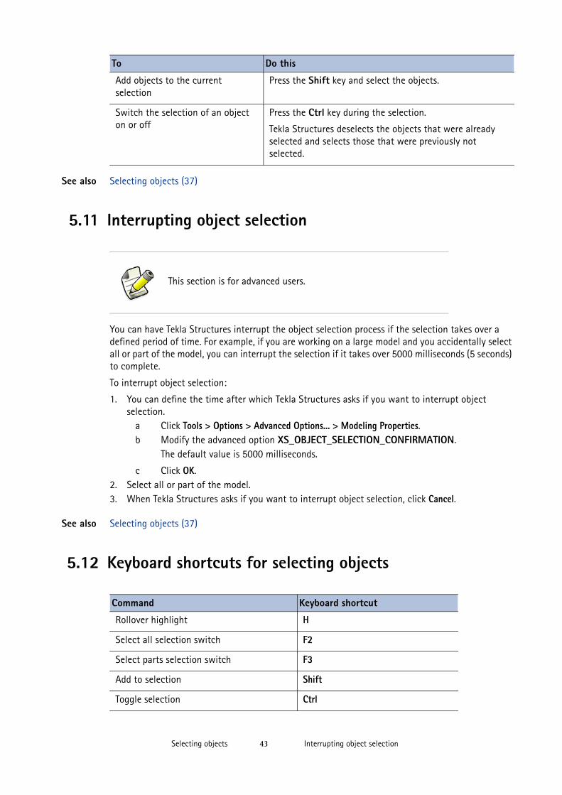
Add objects to the current selection
Press the Shift key and select the objects.
Switch the selection of an object on or off
Press the Ctrl key during the selection.
Tekla Structures deselects the objects that were already selected and selects those that were previously not selected.
This section is for advanced users.
Command Keyboard shortcut
Rollover highlight H
Select all selection switch F2
Select parts selection switch F3
Add to selection Shift
Toggle selection Ctrl
Keyboard shortcuts for selecting objectsSelecting objects 44
See also Selecting objects (37)
Assigning a keyboard shortcut for a command (25)
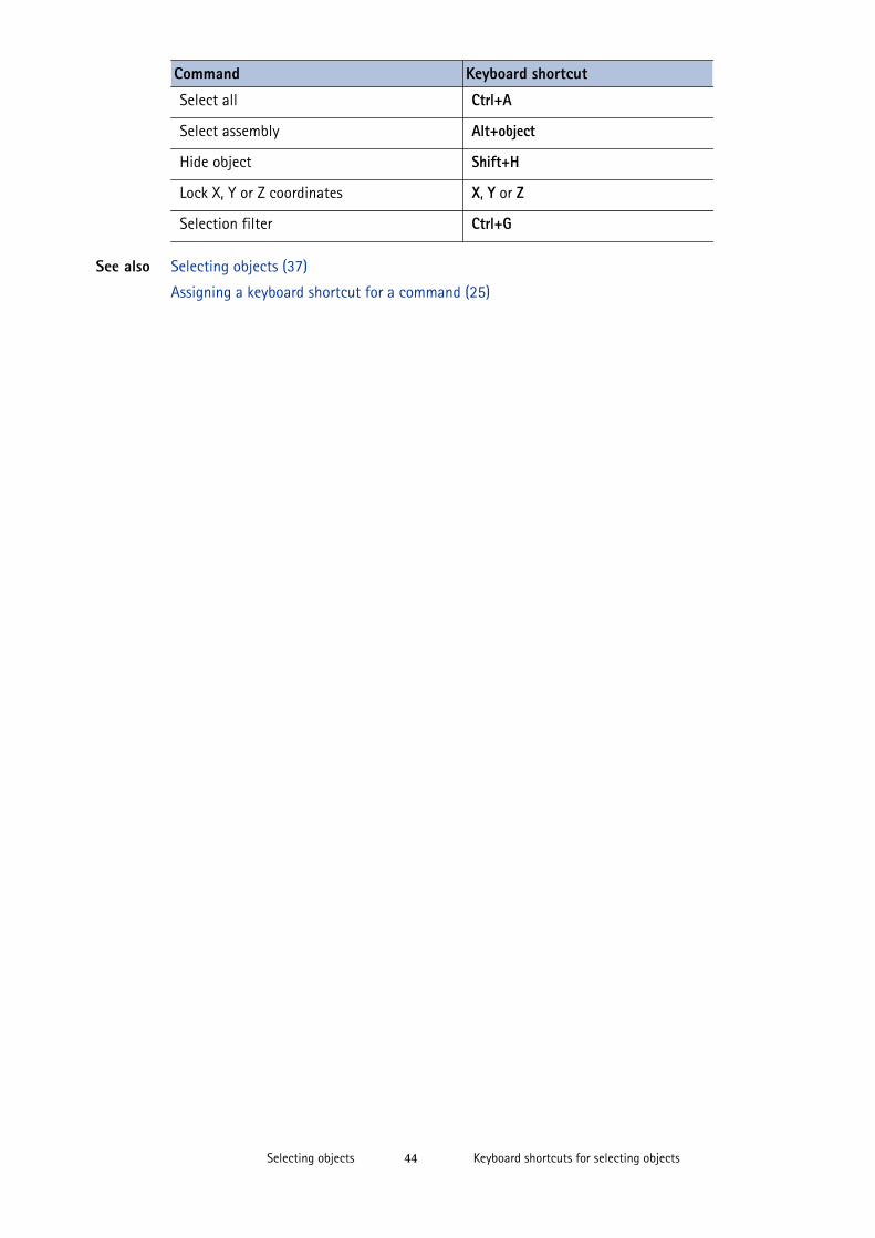
Select all Ctrl+A
Select assembly Alt+object
Hide object Shift+H
Lock X, Y or Z coordinates X, Y or Z
Selection filter Ctrl+G
Command Keyboard shortcut
Duplicate objectsCopying and moving objects 45
6 Copying and moving objects
The basic functionality of copying and moving objects is the same in models and in drawings. You can copy and move objects linearly, with rotation, and with mirroring. Copying creates a new object, leaving the existing object in its original position. Moving relocates the existing object.
If you copy or move objects from an assembly or cast unit, Tekla Structures copies the assembly structure as well, if possible. For example, sub-assemblies are copied as sub-assemblies if a parent object is found.
If you copy or move reinforcements or surface treatments and want them to adapt to the part they are copied or moved to:
• The reinforcement or surface treatment handles must be in part corners.• The parts between which you copy or move must have the same number of cross section
corners.• Circular parts must have the same cross section dimensions.
You can copy and move drawing objects between drawing views that have different scales.
Limitations Tekla Structures cannot create mirrored copies of connection properties. The Copy Special > Mirror... command does not fully mirror objects if they include connections that contain, for example, asymmetrically positioned parts.
See also Duplicate objects (45)
Copying an object (46)
Moving an object (49)
Rotating objects (52)
Mirroring an object (55)
Copying and moving efficiently (85)
Keyboard shortcuts for copying and moving objects (56)
6.1 Duplicate objectsWhen you copy or move objects, Tekla Structures checks for duplicate objects in the location where you are about to copy or move the objects to. Tekla Structures also checks for duplicates if you create new parts in the same location as an existing part.
Two objects are considered duplicates if they have the same orientation and the same size of bounding box. If duplicates are found, you can choose whether to keep or delete the duplicate objects.
Copying an objectCopying and moving objects 46
Use the advanced option XS_DUPLICATE_CHECK_LIMIT_FOR_COPY_AND_MOVE to define the maximum number of objects that can be counted as duplicates while copying or moving objects.
Limitations Tekla Structures does not check for duplicates when you copy objects using a modeling tool, such as the Array of Objects (29) component.
See also Copying and moving objects (45)
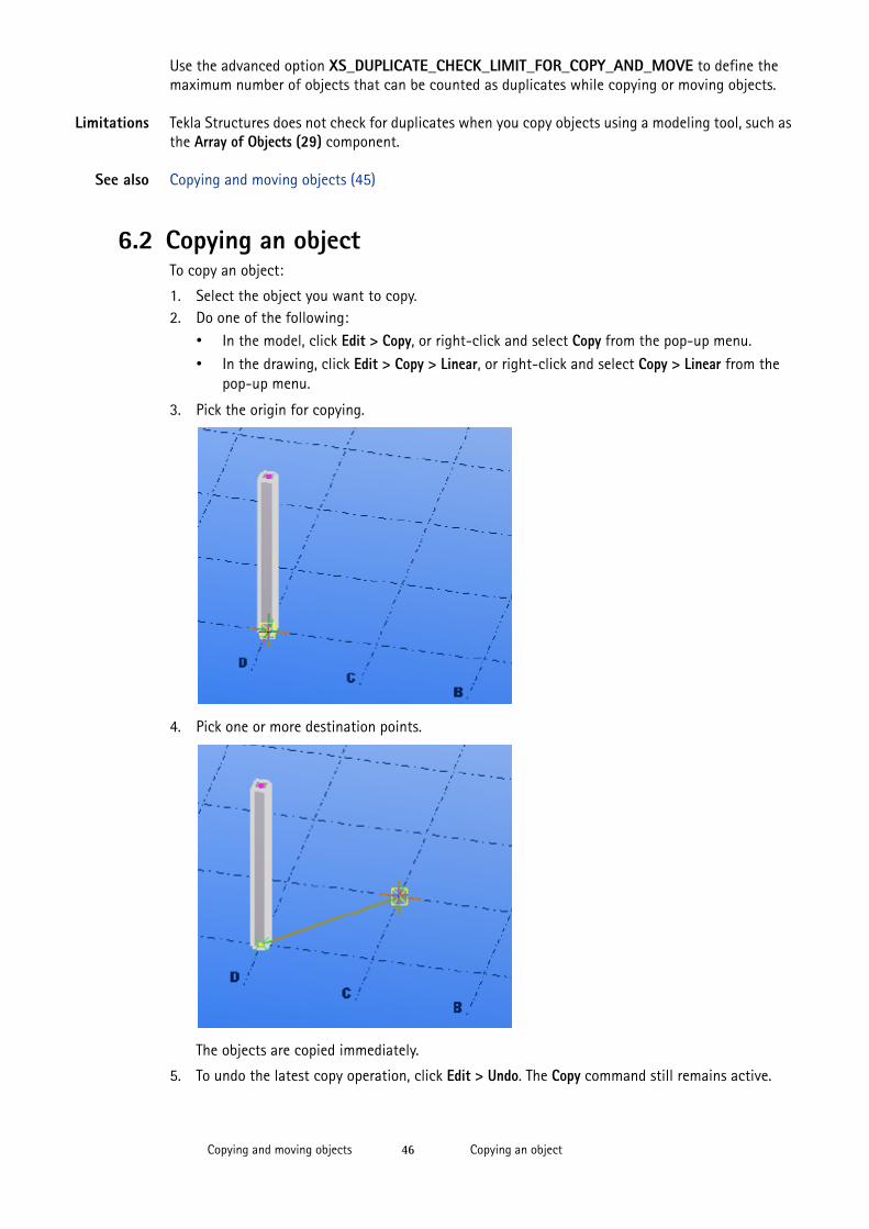
6.2 Copying an objectTo copy an object:
1. Select the object you want to copy.2. Do one of the following:
• In the model, click Edit > Copy, or right-click and select Copy from the pop-up menu.• In the drawing, click Edit > Copy > Linear, or right-click and select Copy > Linear from the
pop-up menu.
3. Pick the origin for copying.
4. Pick one or more destination points.
The objects are copied immediately.
5. To undo the latest copy operation, click Edit > Undo. The Copy command still remains active.
Copying an objectCopying and moving objects 47
6. To stop copying, click Edit > Interrupt.
See also Copying and moving efficiently (85)
Copying an object by specifying distance from origin (47)
Copying an object linearly to a new position (47)
Copying an object using drag-and-drop (48)
Copying an object to another plane (48)
Copying an object to another object (48)
Copying objects from another model (49)
Copying an object by specifying distance from originYou can place objects in a new position in the model or drawing by specifying a distance from the origin. Use the Enter a Numeric Location dialog box to specify the distance.
To copy an object to a new position by specifying a distance:
1. Select the objects you want to copy.2. Click Edit > Copy.3. Pick the origin for copying.4. Move the cursor in the direction you want to copy the objects, but do not pick the point.5. Type the distance.
When you start typing, Tekla Structures displays the Enter a Numeric Location dialog box automatically.
6. Click OK.
See also Copying an object (46)
Snapping to a position using coordinates (66)
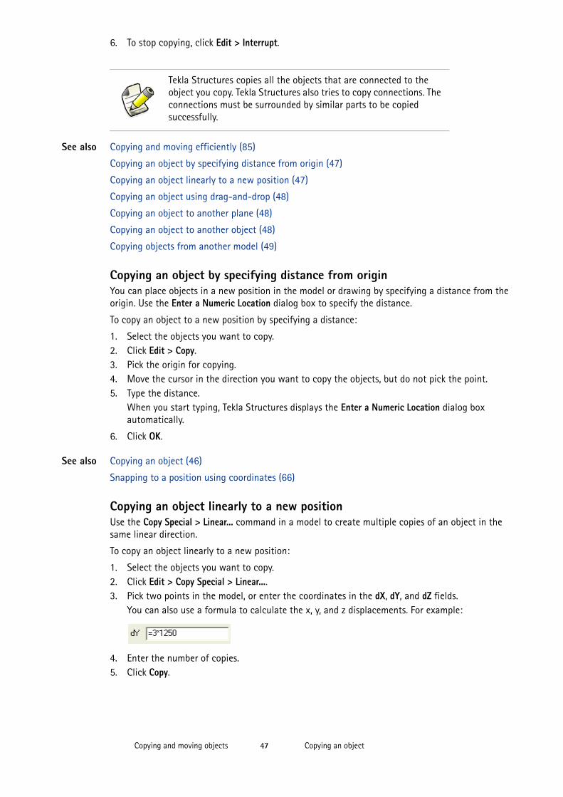
Copying an object linearly to a new positionUse the Copy Special > Linear... command in a model to create multiple copies of an object in the same linear direction.
To copy an object linearly to a new position:
1. Select the objects you want to copy.2. Click Edit > Copy Special > Linear....3. Pick two points in the model, or enter the coordinates in the dX, dY, and dZ fields.
You can also use a formula to calculate the x, y, and z displacements. For example:
4. Enter the number of copies.5. Click Copy.
Tekla Structures copies all the objects that are connected to the object you copy. Tekla Structures also tries to copy connections. The connections must be surrounded by similar parts to be copied successfully.
Copying an objectCopying and moving objects 48
See also Copying an object (46)
Copying an object using drag-and-dropTo copy an object using drag-and-drop:
1. Click Tools > Options > Drag and Drop to activate the command.2. Select the objects you want to copy. 3. Hold down the Ctrl key and the mouse button, and drag the objects to the new position.
See also Copying an object (46)
Copying an object to another planeIn a model, you can copy objects from the first plane you specify to the second (and third, etc.) plane you specify. The position of the copied objects relative to the second (and third, etc.) plane remains the same as the position of the original objects relative to the first plane.
To copy an object to another plane:
1. Select the objects you want to copy.2. Click Edit > Copy Special > To Another Plane.3. Pick the point of origin of the first plane.4. Pick a point on the first plane in the positive x direction.5. Pick a point on the first plane in the positive y direction.6. Repeat steps 3–5 for all destination planes.
See also Copying an object (46)
Copying an object to another objectIn a model, you can copy objects from an object to other similar objects. This is useful, for example, when you detail previously modeled parts. The objects that you can copy between can have different dimensions, length, and rotation.
To copy an object to another object:
1. Select the objects you want to copy.2. Right-click and select Copy Special > To Another Object.3. Select the object to copy from (source object).4. Select the objects to copy to (target object).
See also Copying an object (46)
If the dialog box is open but the command is not active anymore, click the Pick button to re-activate the command.
When you are done with the copying, clear the value fields by clicking Clear to avoid copying new parts accidentally.
To copy grid labels in a drawing, first select the grid label and then either activate the Select grid line selection switch or select the grid label handle.
Moving an objectCopying and moving objects 49
Copying objects from another modelTo copy objects from another model:
1. Click Edit > Copy Special > From Another Model....2. Select the model to copy from in the Model directories list.3. Enter the numbers of the phases from which to copy objects, separated by spaces.
For example, 2 7.
4. Click Copy.5. Close the dialog box.
Limitations You cannot import drawings with the model.
Tekla Structures only copies secondary parts from the model if they belong to the same phase as their main part. This applies to both model and component parts.
See also Copying an object (46)
Phases
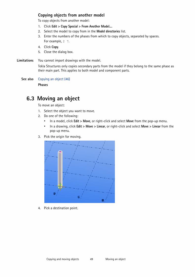
6.3 Moving an objectTo move an object:
1. Select the object you want to move.2. Do one of the following:
• In a model, click Edit > Move, or right-click and select Move from the pop-up menu.
• In a drawing, click Edit > Move > Linear, or right-click and select Move > Linear from the pop-up menu.
3. Pick the origin for moving.
4. Pick a destination point.
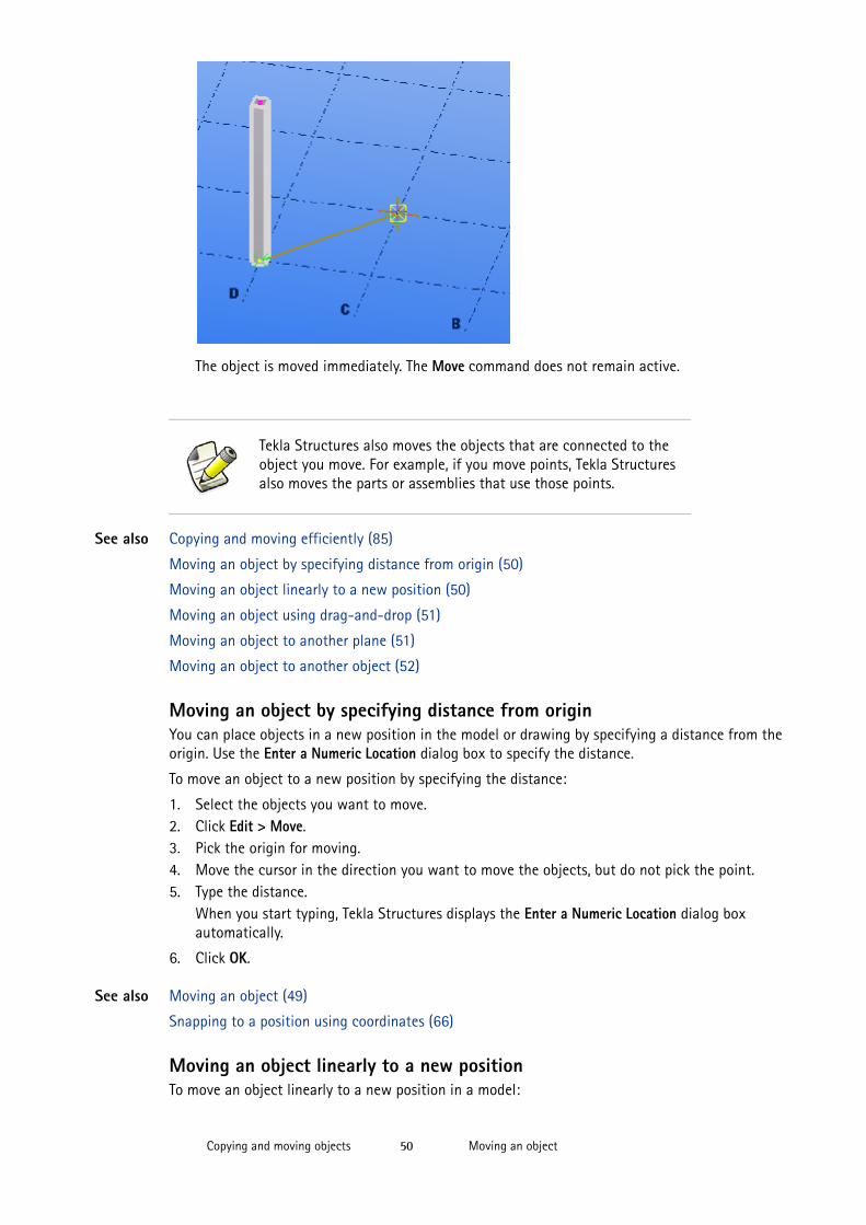
Moving an objectCopying and moving objects 50
The object is moved immediately. The Move command does not remain active.
See also Copying and moving efficiently (85)
Moving an object by specifying distance from origin (50)
Moving an object linearly to a new position (50)
Moving an object using drag-and-drop (51)
Moving an object to another plane (51)
Moving an object to another object (52)
Moving an object by specifying distance from originYou can place objects in a new position in the model or drawing by specifying a distance from the origin. Use the Enter a Numeric Location dialog box to specify the distance.
To move an object to a new position by specifying the distance:
1. Select the objects you want to move.2. Click Edit > Move.3. Pick the origin for moving.4. Move the cursor in the direction you want to move the objects, but do not pick the point.5. Type the distance.
When you start typing, Tekla Structures displays the Enter a Numeric Location dialog box automatically.
6. Click OK.
See also Moving an object (49)
Snapping to a position using coordinates (66)
Moving an object linearly to a new positionTo move an object linearly to a new position in a model:
Tekla Structures also moves the objects that are connected to the object you move. For example, if you move points, Tekla Structures also moves the parts or assemblies that use those points.
Moving an objectCopying and moving objects 51
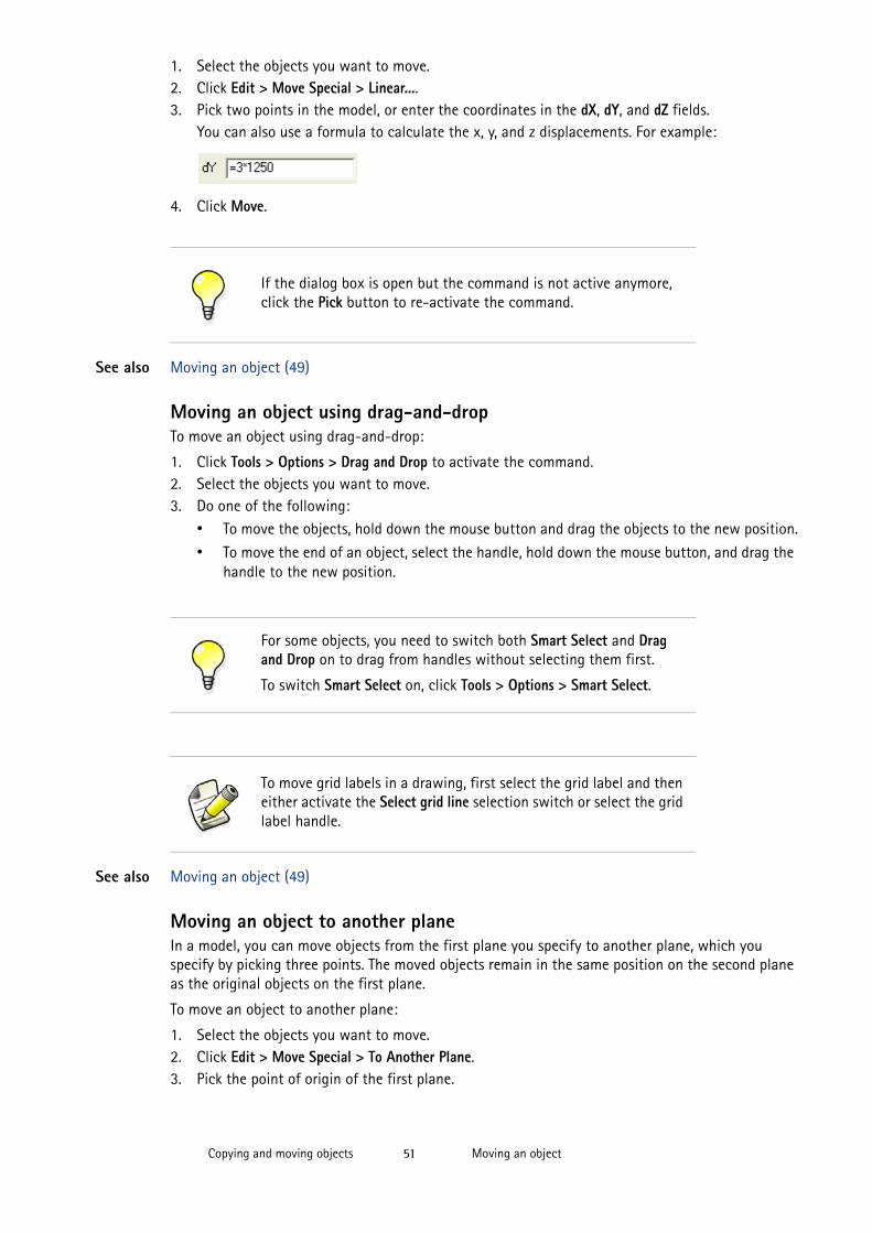
1. Select the objects you want to move.2. Click Edit > Move Special > Linear....3. Pick two points in the model, or enter the coordinates in the dX, dY, and dZ fields.
You can also use a formula to calculate the x, y, and z displacements. For example:
4. Click Move.
See also Moving an object (49)
Moving an object using drag-and-dropTo move an object using drag-and-drop:
1. Click Tools > Options > Drag and Drop to activate the command.2. Select the objects you want to move. 3. Do one of the following:
• To move the objects, hold down the mouse button and drag the objects to the new position.
• To move the end of an object, select the handle, hold down the mouse button, and drag the handle to the new position.
See also Moving an object (49)
Moving an object to another planeIn a model, you can move objects from the first plane you specify to another plane, which you specify by picking three points. The moved objects remain in the same position on the second plane as the original objects on the first plane.
To move an object to another plane:
1. Select the objects you want to move.2. Click Edit > Move Special > To Another Plane.3. Pick the point of origin of the first plane.
If the dialog box is open but the command is not active anymore, click the Pick button to re-activate the command.
For some objects, you need to switch both Smart Select and Drag and Drop on to drag from handles without selecting them first.
To switch Smart Select on, click Tools > Options > Smart Select.
To move grid labels in a drawing, first select the grid label and then either activate the Select grid line selection switch or select the grid label handle.
Rotating objectsCopying and moving objects 52
4. Pick a point on the first plane in the positive x direction.5. Pick a point on the first plane in the positive y direction.6. Repeat steps 3–5 for the destination plane.
See also Moving an object (49)
Moving an object to another objectIn a model, you can move objects from an object to other, similar objects. This is useful, for example, when you detail previously modeled parts. The objects that you move between can have different dimensions, length, and rotation.
To move an object to another object:
1. Select the objects you want to move.2. Right-click and select Move Special > To Another Object from the pop-up menu.3. Select the object to move from (source object).4. Select the objects to move to (target object).
See also Moving an object (49)
6.4 Rotating objectsYou can copy or move an object in a model by rotating it around any line you choose. In a drawing, you can copy or move an object by rotating it around a given line on the work plane.
Positive rotation is according to the right-hand rule (clockwise when looking from the starting point of the rotation axis).
See also Rotating an object around a line (52)
Rotating an object around the z axis (53)
Rotating drawing objects on the work plane (55)
Right-hand rule
Rotating an object around a lineUse the line option when you want to copy and rotate, or move and rotate objects around any given line in the model.
To rotate an object around a line:
1. Select the objects you want to copy or move.2. Activate the rotation command.
• To copy and rotate the objects, click Edit > Copy Special > Rotate...• To move and rotate the objects, click Edit > Move Special > Rotate...
3. Select line in the Around list box.4. Pick the start point of the rotation axis, or enter its coordinates.5. Pick the end point of the rotation axis, or enter its coordinates.6. If you are copying, enter the number of copies.7. If needed, enter the dZ value, which is the difference in position between the original and
copied object in the z direction.8. Enter the rotation angle.9. Click Copy or Move.
The objects are rotated accordingly.
Rotating objectsCopying and moving objects 53
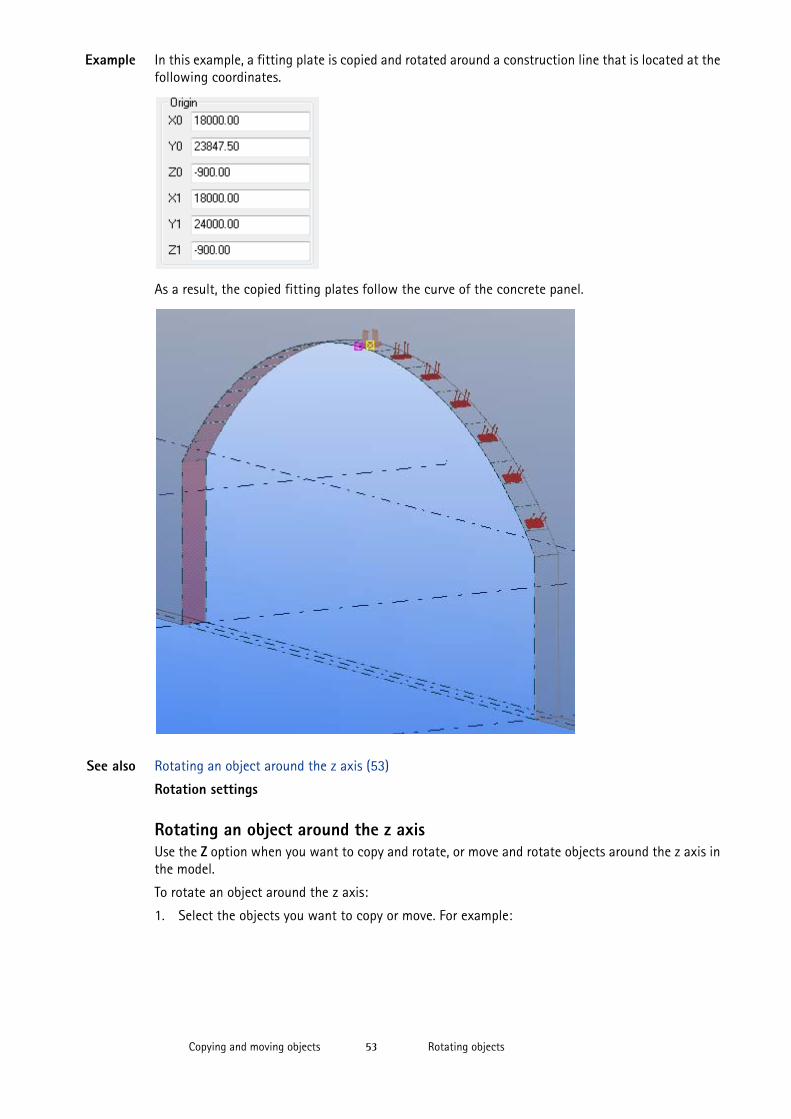
Example In this example, a fitting plate is copied and rotated around a construction line that is located at the following coordinates.
As a result, the copied fitting plates follow the curve of the concrete panel.
See also Rotating an object around the z axis (53)
Rotation settings
Rotating an object around the z axisUse the Z option when you want to copy and rotate, or move and rotate objects around the z axis in the model.
To rotate an object around the z axis:
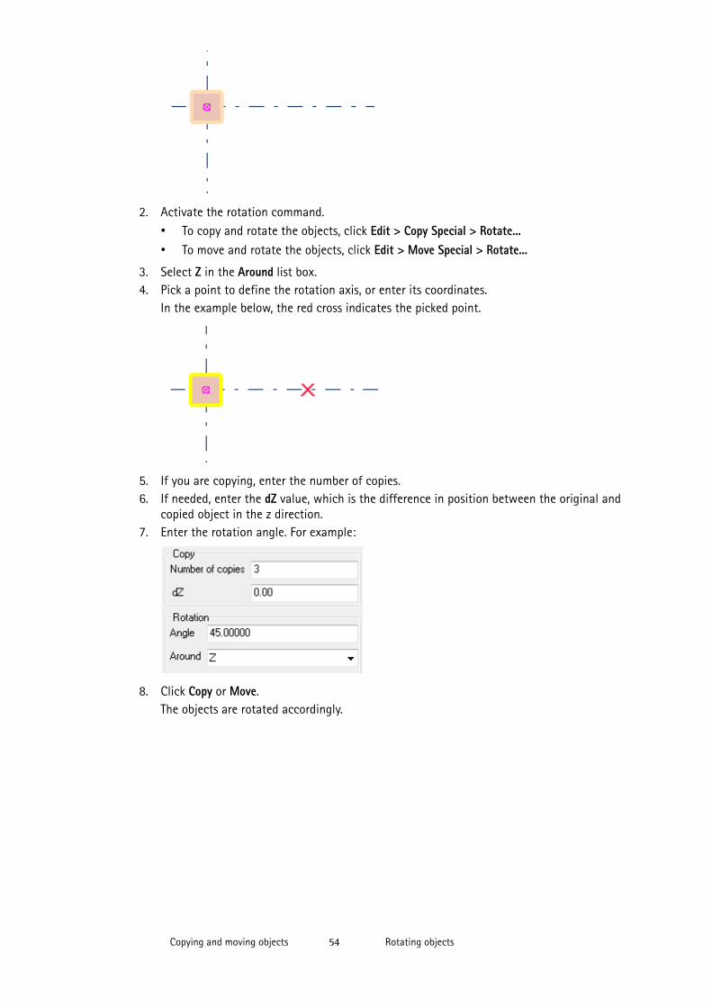
1. Select the objects you want to copy or move. For example:
Rotating objectsCopying and moving objects 54
2. Activate the rotation command.• To copy and rotate the objects, click Edit > Copy Special > Rotate...• To move and rotate the objects, click Edit > Move Special > Rotate...
3. Select Z in the Around list box.4. Pick a point to define the rotation axis, or enter its coordinates.
In the example below, the red cross indicates the picked point.
5. If you are copying, enter the number of copies.6. If needed, enter the dZ value, which is the difference in position between the original and
copied object in the z direction.7. Enter the rotation angle. For example:
8. Click Copy or Move.The objects are rotated accordingly.
Mirroring an objectCopying and moving objects 55
See also Rotating an object around a line (52)
Rotation settings
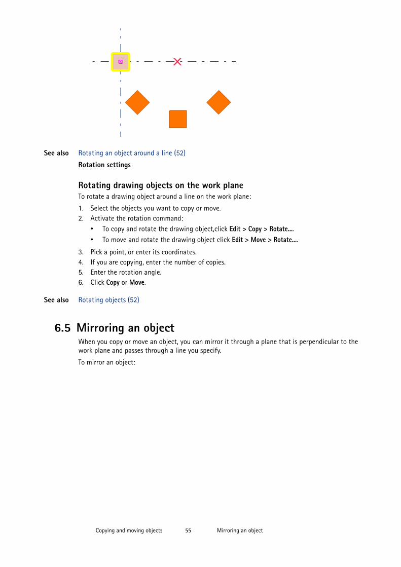
Rotating drawing objects on the work plane To rotate a drawing object around a line on the work plane:
1. Select the objects you want to copy or move.2. Activate the rotation command:
• To copy and rotate the drawing object,click Edit > Copy > Rotate....• To move and rotate the drawing object click Edit > Move > Rotate....
3. Pick a point, or enter its coordinates.4. If you are copying, enter the number of copies.5. Enter the rotation angle.6. Click Copy or Move.
See also Rotating objects (52)
6.5 Mirroring an objectWhen you copy or move an object, you can mirror it through a plane that is perpendicular to the work plane and passes through a line you specify.
To mirror an object:
Keyboard shortcuts for copying and moving objectsCopying and moving objects 56
See also Copying and moving objects (45)
6.6 Keyboard shortcuts for copying and moving objects
See also Copying and moving objects (45)
Assigning a keyboard shortcut for a command (25)
To Do this
Mirror in the model 1. Select the objects you want to copy or move.2. Activate the mirroring command:
• To copy and mirror the objects, click Edit > Copy Special > Mirror...
• To move and mirror the objects, click Edit > Move Special > Mirror...
3. Pick the start point of the mirroring plane, or enter its coordinates.
4. Pick the end point of the mirroring plane, or enter its coordinates.
5. Enter the angle.6. Click Copy or Move.
Mirror in the drawing 1. Select the objects you want to copy or move.2. Activate the mirroring command:
• To copy and mirror the objects, click Edit > Copy > Mirror...• To move and mirror the objects, click Edit > Move > Mirror...
3. Pick the start point of the mirroring plane, or enter its coordinates.
4. Pick the end point of the mirroring plane, or enter its coordinates.
5. Enter the angle.6. Click Copy or Move.
Command Keyboard shortcut
Copy Ctrl+C
Move Ctrl+M
Smart Select S
Drag and drop D
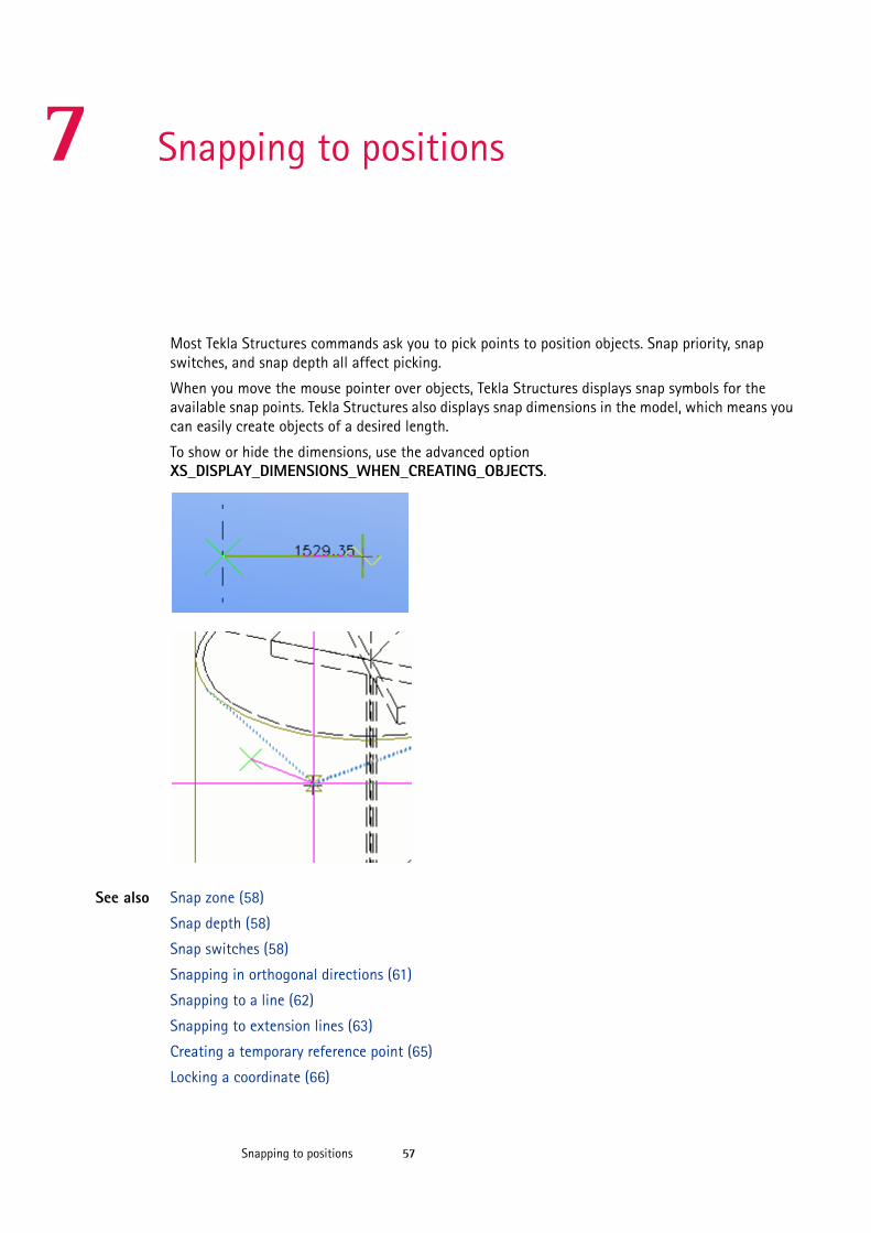
Snapping to positions 57
7 Snapping to positions
Most Tekla Structures commands ask you to pick points to position objects. Snap priority, snap switches, and snap depth all affect picking.
When you move the mouse pointer over objects, Tekla Structures displays snap symbols for the available snap points. Tekla Structures also displays snap dimensions in the model, which means you can easily create objects of a desired length.
To show or hide the dimensions, use the advanced option XS_DISPLAY_DIMENSIONS_WHEN_CREATING_OBJECTS.
See also Snap zone (58)
Snap depth (58)
Snap switches (58)
Snapping in orthogonal directions (61)
Snapping to a line (62)
Snapping to extension lines (63)
Creating a temporary reference point (65)
Locking a coordinate (66)
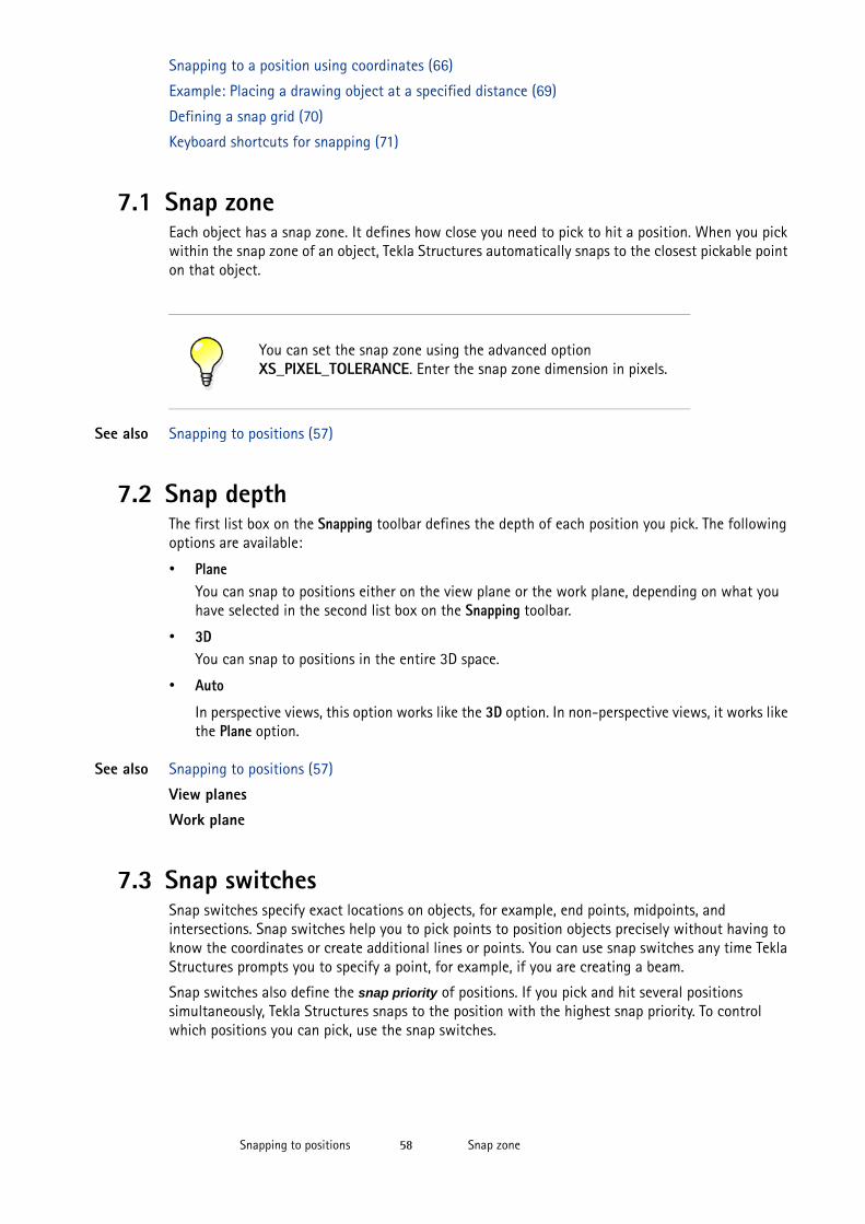
Snap zoneSnapping to positions 58
Snapping to a position using coordinates (66)
Example: Placing a drawing object at a specified distance (69)
Defining a snap grid (70)
Keyboard shortcuts for snapping (71)
7.1 Snap zoneEach object has a snap zone. It defines how close you need to pick to hit a position. When you pick within the snap zone of an object, Tekla Structures automatically snaps to the closest pickable point on that object.
See also Snapping to positions (57)
7.2 Snap depthThe first list box on the Snapping toolbar defines the depth of each position you pick. The following options are available:
• PlaneYou can snap to positions either on the view plane or the work plane, depending on what you have selected in the second list box on the Snapping toolbar.
• 3DYou can snap to positions in the entire 3D space.
• Auto
In perspective views, this option works like the 3D option. In non-perspective views, it works like the Plane option.
See also Snapping to positions (57)
View planes
Work plane
7.3 Snap switchesSnap switches specify exact locations on objects, for example, end points, midpoints, and intersections. Snap switches help you to pick points to position objects precisely without having to know the coordinates or create additional lines or points. You can use snap switches any time Tekla Structures prompts you to specify a point, for example, if you are creating a beam.
Snap switches also define the snap priority of positions. If you pick and hit several positions simultaneously, Tekla Structures snaps to the position with the highest snap priority. To control which positions you can pick, use the snap switches.
You can set the snap zone using the advanced option XS_PIXEL_TOLERANCE. Enter the snap zone dimension in pixels.
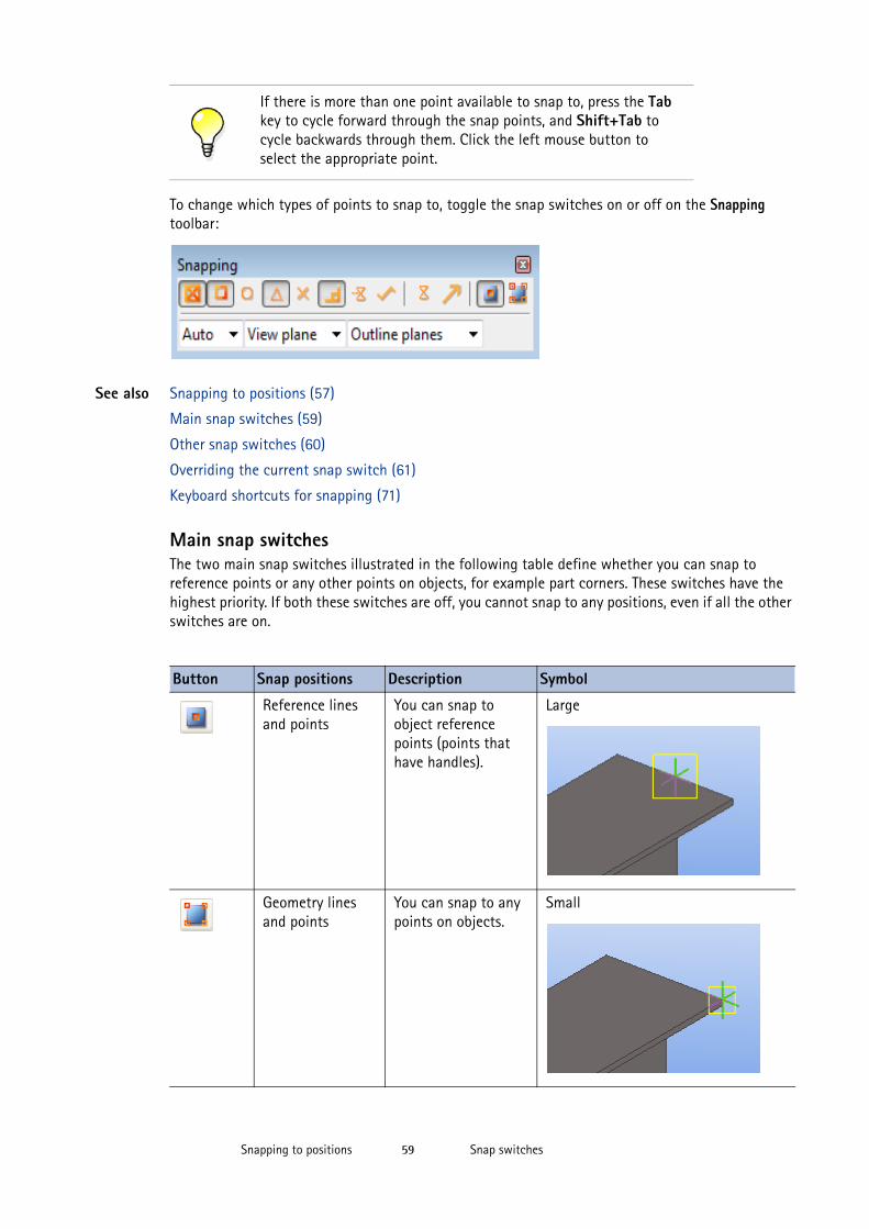
Snap switchesSnapping to positions 59
To change which types of points to snap to, toggle the snap switches on or off on the Snapping toolbar:
See also Snapping to positions (57)
Main snap switches (59)
Other snap switches (60)
Overriding the current snap switch (61)
Keyboard shortcuts for snapping (71)
Main snap switchesThe two main snap switches illustrated in the following table define whether you can snap to reference points or any other points on objects, for example part corners. These switches have the highest priority. If both these switches are off, you cannot snap to any positions, even if all the other switches are on.
If there is more than one point available to snap to, press the Tab key to cycle forward through the snap points, and Shift+Tab to cycle backwards through them. Click the left mouse button to select the appropriate point.
Button Snap positions Description Symbol
Reference lines and points
You can snap to object reference points (points that have handles).
Large
Geometry lines and points
You can snap to any points on objects.
Small
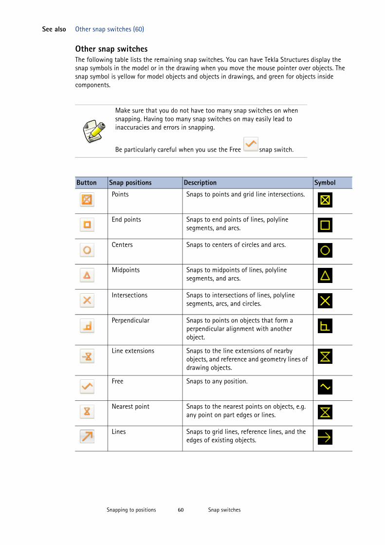
Snap switchesSnapping to positions 60
See also Other snap switches (60)
Other snap switchesThe following table lists the remaining snap switches. You can have Tekla Structures display the snap symbols in the model or in the drawing when you move the mouse pointer over objects. The snap symbol is yellow for model objects and objects in drawings, and green for objects inside components.
Make sure that you do not have too many snap switches on when snapping. Having too many snap switches on may easily lead to inaccuracies and errors in snapping.
Be particularly careful when you use the Free snap switch.
Button Snap positions Description Symbol
Points Snaps to points and grid line intersections.
End points Snaps to end points of lines, polyline segments, and arcs.
Centers Snaps to centers of circles and arcs.
Midpoints Snaps to midpoints of lines, polyline segments, and arcs.
Intersections Snaps to intersections of lines, polyline segments, arcs, and circles.
Perpendicular Snaps to points on objects that form a perpendicular alignment with another object.
Line extensions Snaps to the line extensions of nearby objects, and reference and geometry lines of drawing objects.
Free Snaps to any position.
Nearest point Snaps to the nearest points on objects, e.g. any point on part edges or lines.
Lines Snaps to grid lines, reference lines, and the edges of existing objects.
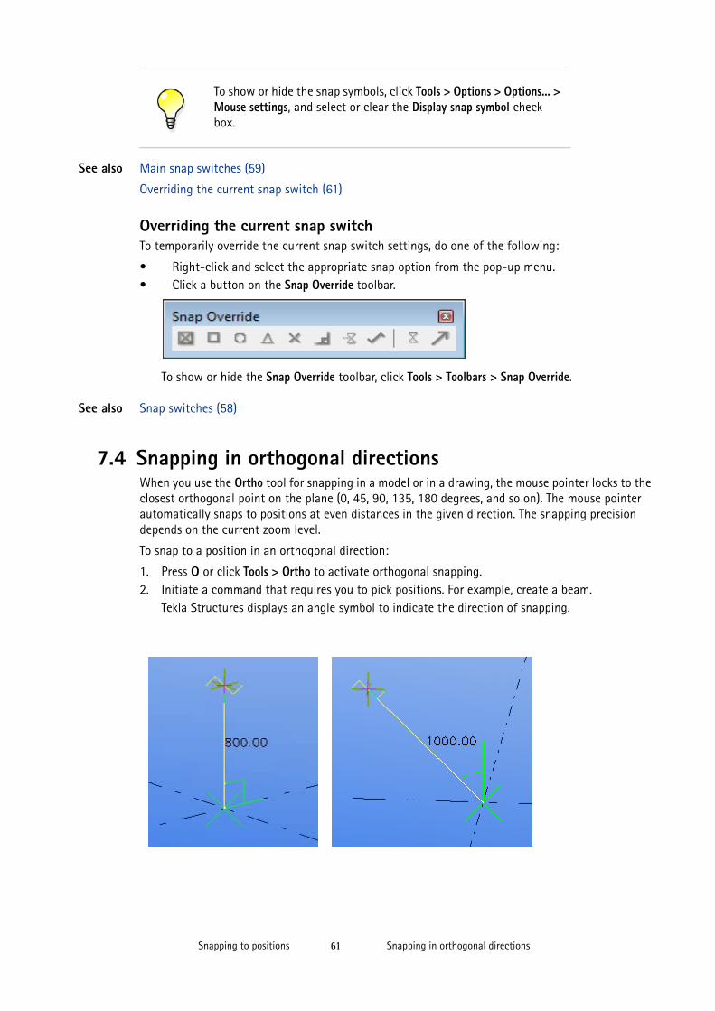
Snapping in orthogonal directionsSnapping to positions 61
See also Main snap switches (59)
Overriding the current snap switch (61)
Overriding the current snap switchTo temporarily override the current snap switch settings, do one of the following:
• Right-click and select the appropriate snap option from the pop-up menu.• Click a button on the Snap Override toolbar.
To show or hide the Snap Override toolbar, click Tools > Toolbars > Snap Override.
See also Snap switches (58)
7.4 Snapping in orthogonal directionsWhen you use the Ortho tool for snapping in a model or in a drawing, the mouse pointer locks to the closest orthogonal point on the plane (0, 45, 90, 135, 180 degrees, and so on). The mouse pointer automatically snaps to positions at even distances in the given direction. The snapping precision depends on the current zoom level.
To snap to a position in an orthogonal direction:
1. Press O or click Tools > Ortho to activate orthogonal snapping.2. Initiate a command that requires you to pick positions. For example, create a beam.
Tekla Structures displays an angle symbol to indicate the direction of snapping.
To show or hide the snap symbols, click Tools > Options > Options... > Mouse settings, and select or clear the Display snap symbol check box.
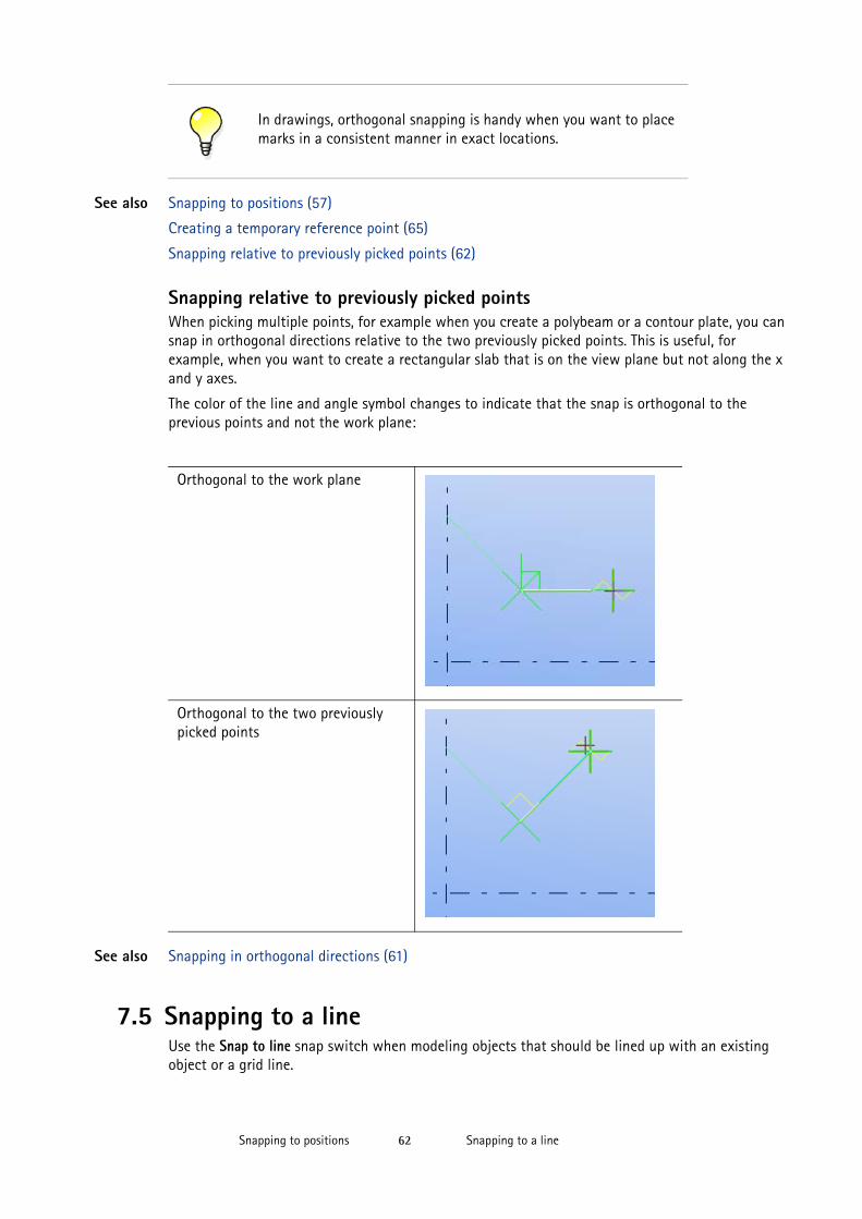
Snapping to a lineSnapping to positions 62
See also Snapping to positions (57)
Creating a temporary reference point (65)
Snapping relative to previously picked points (62)
Snapping relative to previously picked pointsWhen picking multiple points, for example when you create a polybeam or a contour plate, you can snap in orthogonal directions relative to the two previously picked points. This is useful, for example, when you want to create a rectangular slab that is on the view plane but not along the x and y axes.
The color of the line and angle symbol changes to indicate that the snap is orthogonal to the previous points and not the work plane:
See also Snapping in orthogonal directions (61)
7.5 Snapping to a lineUse the Snap to line snap switch when modeling objects that should be lined up with an existing object or a grid line.
In drawings, orthogonal snapping is handy when you want to place marks in a consistent manner in exact locations.
Orthogonal to the work plane
Orthogonal to the two previously picked points
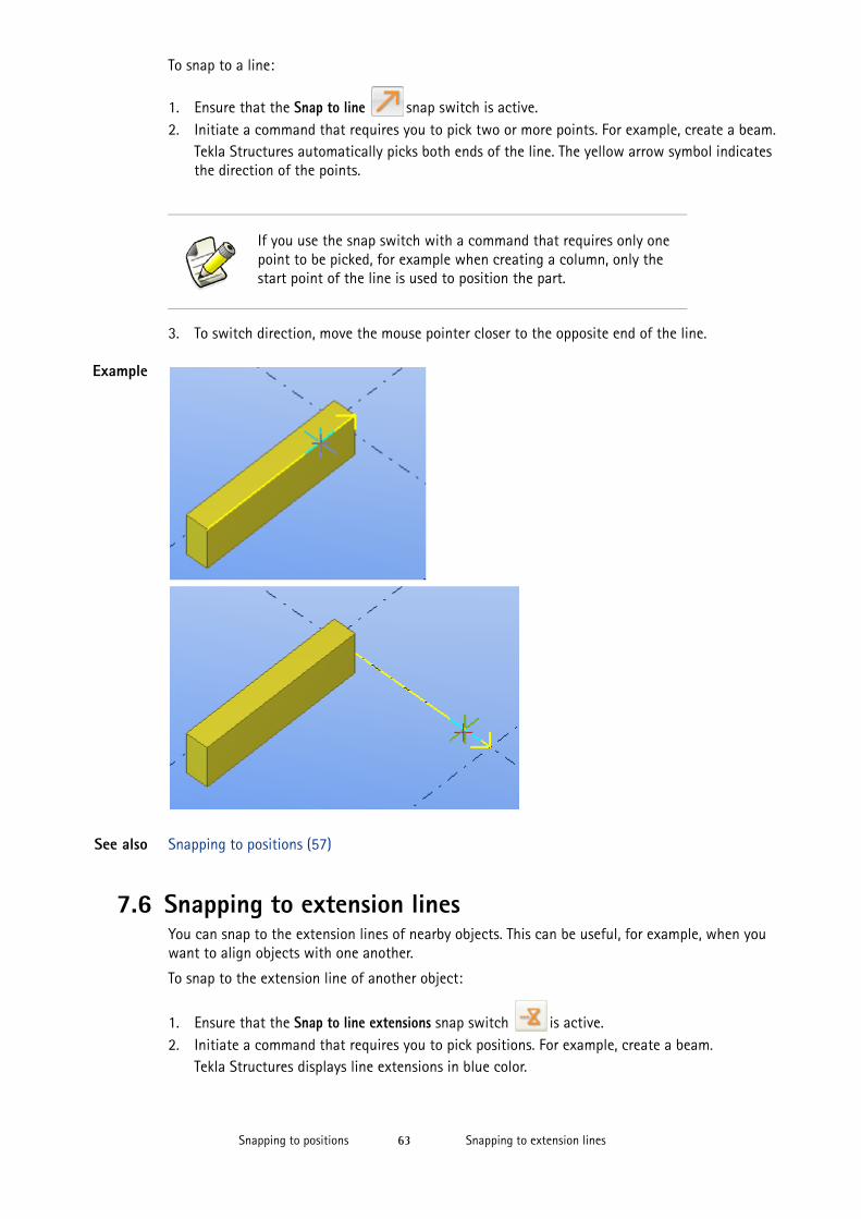
Snapping to extension linesSnapping to positions 63
To snap to a line:
1. Ensure that the Snap to line snap switch is active. 2. Initiate a command that requires you to pick two or more points. For example, create a beam.
Tekla Structures automatically picks both ends of the line. The yellow arrow symbol indicates the direction of the points.
3. To switch direction, move the mouse pointer closer to the opposite end of the line.
Example
See also Snapping to positions (57)
7.6 Snapping to extension linesYou can snap to the extension lines of nearby objects. This can be useful, for example, when you want to align objects with one another.
To snap to the extension line of another object:
1. Ensure that the Snap to line extensions snap switch is active.2. Initiate a command that requires you to pick positions. For example, create a beam.
Tekla Structures displays line extensions in blue color.
If you use the snap switch with a command that requires only one point to be picked, for example when creating a column, only the start point of the line is used to position the part.
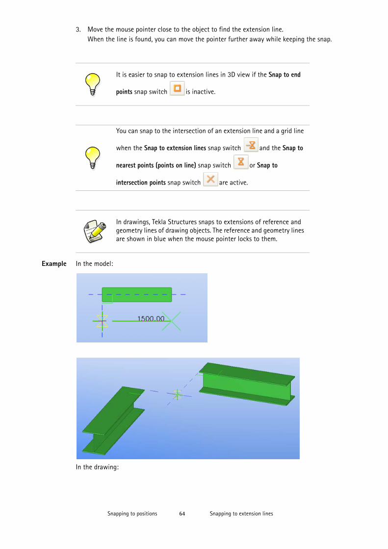
Snapping to extension linesSnapping to positions 64
3. Move the mouse pointer close to the object to find the extension line.When the line is found, you can move the pointer further away while keeping the snap.
Example In the model:
In the drawing:
It is easier to snap to extension lines in 3D view if the Snap to end
points snap switch is inactive.
You can snap to the intersection of an extension line and a grid line
when the Snap to extension lines snap switch and the Snap to
nearest points (points on line) snap switch or Snap to
intersection points snap switch are active.
In drawings, Tekla Structures snaps to extensions of reference and geometry lines of drawing objects. The reference and geometry lines are shown in blue when the mouse pointer locks to them.
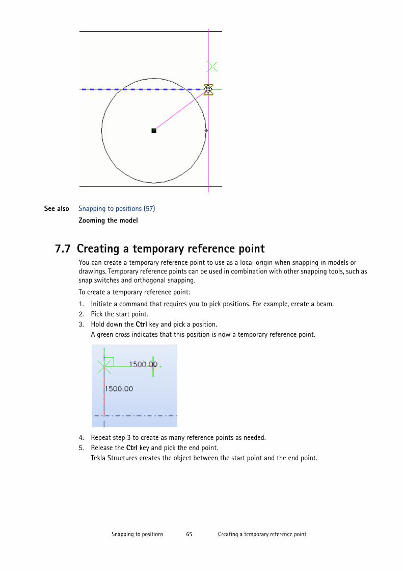
Creating a temporary reference pointSnapping to positions 65
See also Snapping to positions (57)
Zooming the model
7.7 Creating a temporary reference pointYou can create a temporary reference point to use as a local origin when snapping in models or drawings. Temporary reference points can be used in combination with other snapping tools, such as snap switches and orthogonal snapping.
To create a temporary reference point:
1. Initiate a command that requires you to pick positions. For example, create a beam.2. Pick the start point.3. Hold down the Ctrl key and pick a position.
A green cross indicates that this position is now a temporary reference point.
4. Repeat step 3 to create as many reference points as needed.5. Release the Ctrl key and pick the end point.
Tekla Structures creates the object between the start point and the end point.
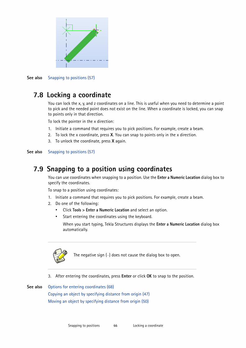
Locking a coordinateSnapping to positions 66
See also Snapping to positions (57)
7.8 Locking a coordinateYou can lock the x, y, and z coordinates on a line. This is useful when you need to determine a point to pick and the needed point does not exist on the line. When a coordinate is locked, you can snap to points only in that direction.
To lock the pointer in the x direction:
1. Initiate a command that requires you to pick positions. For example, create a beam.2. To lock the x coordinate, press X. You can snap to points only in the x direction.3. To unlock the coordinate, press X again.
See also Snapping to positions (57)
7.9 Snapping to a position using coordinatesYou can use coordinates when snapping to a position. Use the Enter a Numeric Location dialog box to specify the coordinates.
To snap to a position using coordinates:
1. Initiate a command that requires you to pick positions. For example, create a beam.2. Do one of the following:
• Click Tools > Enter a Numeric Location and select an option.
• Start entering the coordinates using the keyboard.
When you start typing, Tekla Structures displays the Enter a Numeric Location dialog box automatically.
3. After entering the coordinates, press Enter or click OK to snap to the position.
See also Options for entering coordinates (68)
Copying an object by specifying distance from origin (47)
Moving an object by specifying distance from origin (50)
The negative sign (-) does not cause the dialog box to open.
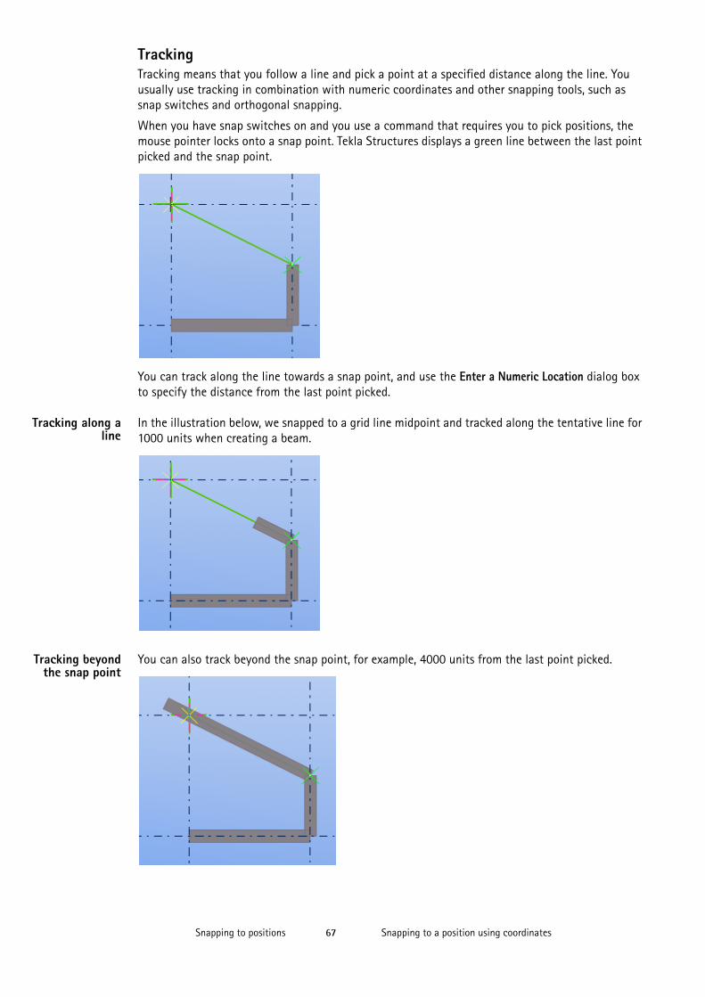
Snapping to a position using coordinatesSnapping to positions 67
TrackingTracking means that you follow a line and pick a point at a specified distance along the line. You usually use tracking in combination with numeric coordinates and other snapping tools, such as snap switches and orthogonal snapping.
When you have snap switches on and you use a command that requires you to pick positions, the mouse pointer locks onto a snap point. Tekla Structures displays a green line between the last point picked and the snap point.
You can track along the line towards a snap point, and use the Enter a Numeric Location dialog box to specify the distance from the last point picked.
Tracking along aline
In the illustration below, we snapped to a grid line midpoint and tracked along the tentative line for 1000 units when creating a beam.
Tracking beyondthe snap point
You can also track beyond the snap point, for example, 4000 units from the last point picked.
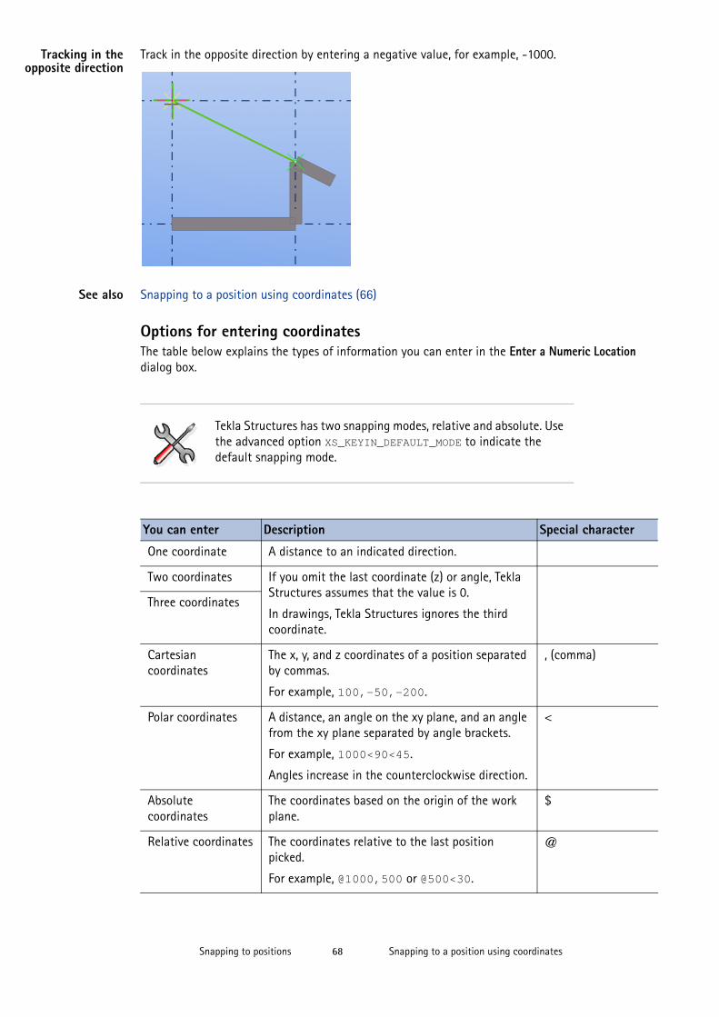
Snapping to a position using coordinatesSnapping to positions 68
Tracking in theopposite direction
Track in the opposite direction by entering a negative value, for example, -1000.
See also Snapping to a position using coordinates (66)
Options for entering coordinatesThe table below explains the types of information you can enter in the Enter a Numeric Location dialog box.
Tekla Structures has two snapping modes, relative and absolute. Use the advanced option XS_KEYIN_DEFAULT_MODE to indicate the default snapping mode.
You can enter Description Special character
One coordinate A distance to an indicated direction.
Two coordinates If you omit the last coordinate (z) or angle, Tekla Structures assumes that the value is 0.
In drawings, Tekla Structures ignores the third coordinate.
Three coordinates
Cartesian coordinates
The x, y, and z coordinates of a position separated by commas.
For example, 100,-50,-200.
, (comma)
Polar coordinates A distance, an angle on the xy plane, and an angle from the xy plane separated by angle brackets.
For example, 1000<90<45.
Angles increase in the counterclockwise direction.
<
Absolute coordinates
The coordinates based on the origin of the work plane.
$
Relative coordinates The coordinates relative to the last position picked.
For example, @1000,500 or @500<30.
@
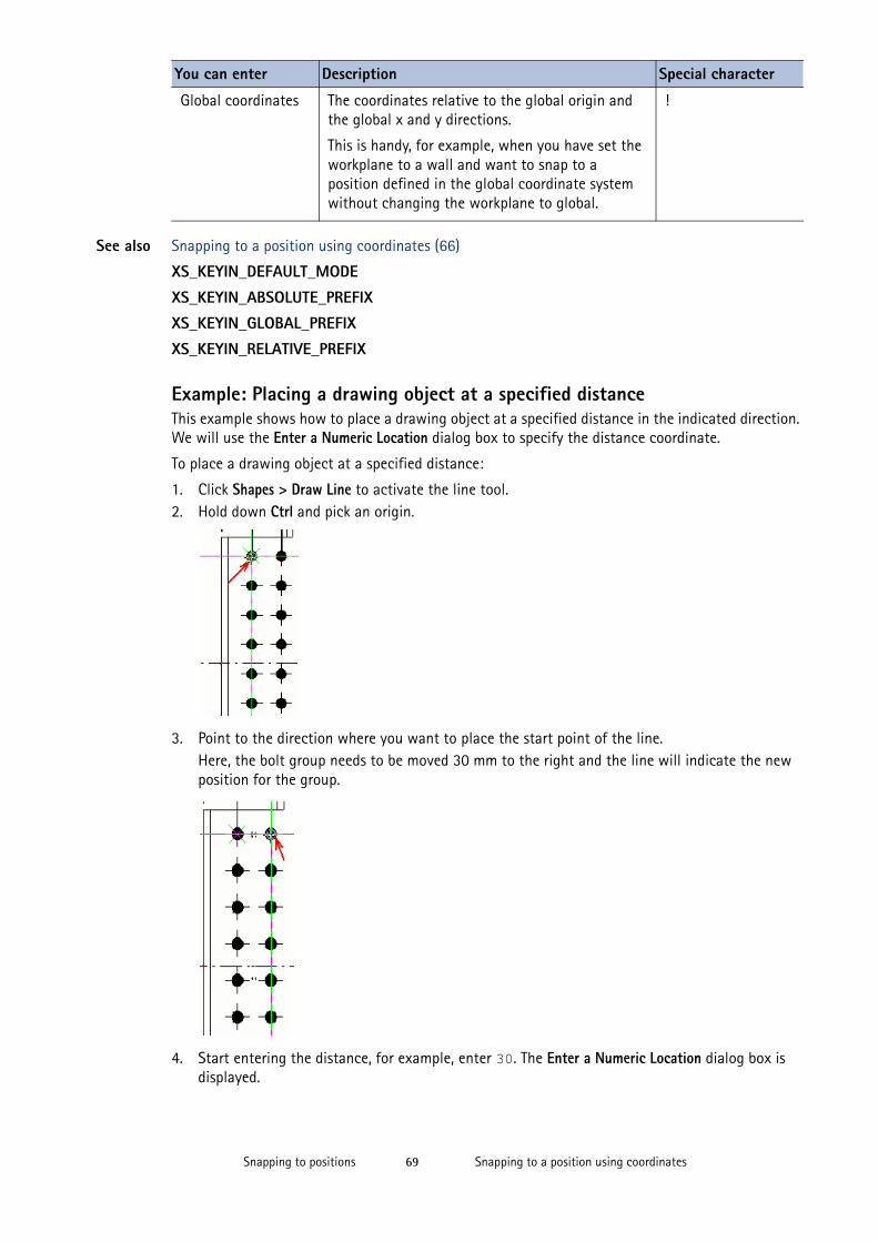
Snapping to a position using coordinatesSnapping to positions 69
See also Snapping to a position using coordinates (66)
XS_KEYIN_DEFAULT_MODE
XS_KEYIN_ABSOLUTE_PREFIX
XS_KEYIN_GLOBAL_PREFIX
XS_KEYIN_RELATIVE_PREFIX
Example: Placing a drawing object at a specified distanceThis example shows how to place a drawing object at a specified distance in the indicated direction. We will use the Enter a Numeric Location dialog box to specify the distance coordinate.
To place a drawing object at a specified distance:
1. Click Shapes > Draw Line to activate the line tool.2. Hold down Ctrl and pick an origin.
3. Point to the direction where you want to place the start point of the line. Here, the bolt group needs to be moved 30 mm to the right and the line will indicate the new position for the group.
4. Start entering the distance, for example, enter 30. The Enter a Numeric Location dialog box is displayed.
Global coordinates The coordinates relative to the global origin and the global x and y directions.
This is handy, for example, when you have set the workplane to a wall and want to snap to a position defined in the global coordinate system without changing the workplane to global.
!
You can enter Description Special character
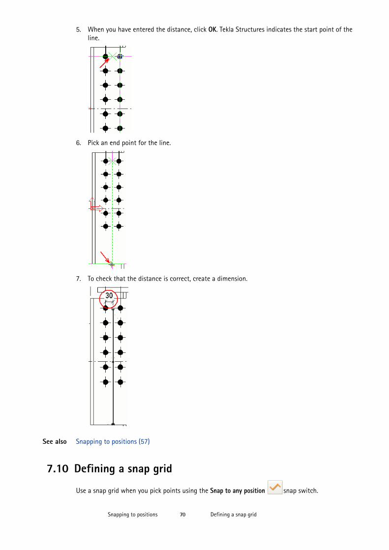
Defining a snap gridSnapping to positions 70
5. When you have entered the distance, click OK. Tekla Structures indicates the start point of the line.
6. Pick an end point for the line.
7. To check that the distance is correct, create a dimension.
See also Snapping to positions (57)
7.10 Defining a snap grid
Use a snap grid when you pick points using the Snap to any position snap switch.
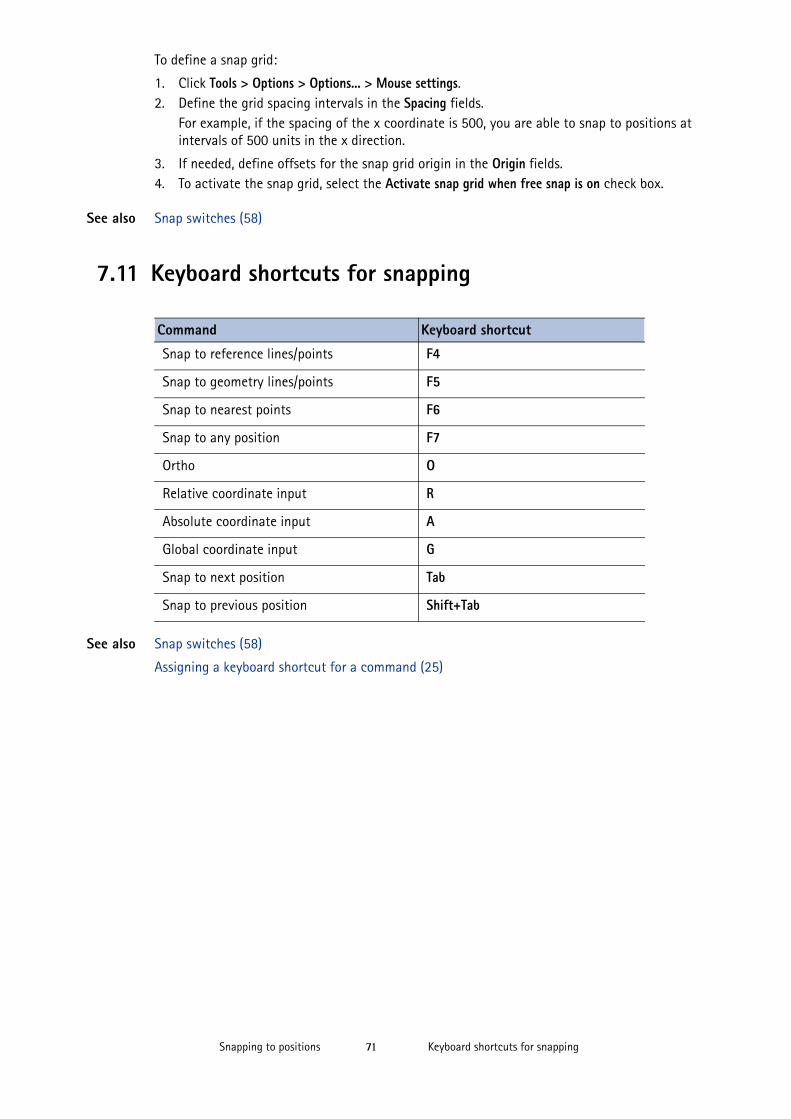
Keyboard shortcuts for snappingSnapping to positions 71
To define a snap grid:
1. Click Tools > Options > Options... > Mouse settings. 2. Define the grid spacing intervals in the Spacing fields.
For example, if the spacing of the x coordinate is 500, you are able to snap to positions at intervals of 500 units in the x direction.
3. If needed, define offsets for the snap grid origin in the Origin fields.4. To activate the snap grid, select the Activate snap grid when free snap is on check box.
See also Snap switches (58)
7.11 Keyboard shortcuts for snapping
See also Snap switches (58)
Assigning a keyboard shortcut for a command (25)
Command Keyboard shortcut
Snap to reference lines/points F4
Snap to geometry lines/points F5
Snap to nearest points F6
Snap to any position F7
Ortho O
Relative coordinate input R
Absolute coordinate input A
Global coordinate input G
Snap to next position Tab
Snap to previous position Shift+Tab

Keyboard shortcuts for snappingSnapping to positions 72
Filtering objects using a view filterFiltering objects 73
8 Filtering objects
Filters allow you to view and/or select objects that have only certain characteristics. This can be useful when you want to perform an operation on several objects at the same time.
You can create filters of your own, or you can use any of the standard filters available in Tekla Structures.
Example Create a selection filter for a rule set in the Master Drawing Catalog to automatically create drawings of desired objects. For example, if you only want to produce drawings of the beams in the model, use a selection filter to select the beams.
See also Filtering objects using a view filter (73)
Filtering objects using a selection filter (74)
Filtering examples (77)
Possible values in filtering (81)
Copying a filter to another model (82)
Deleting a filter (83)
8.1 Filtering objects using a view filterView filters define which objects are displayed in a view, based on object properties. The work area, view depth, view setup, and object representation settings also affect the visibility of objects.
To filter objects using a view filter:
1. Double-click the view to open the View Properties dialog box.2. Select a filter from the Visible object group list box.3. Click Modify.
Only objects allowed by the filter are displayed.
See also Creating a view filter (73)
Filtering examples (77)
Creating a view filterTo create a view filter:
1. Double-click the view to open the View Properties dialog box.2. Click Object group... to open the Object Group - View Filter dialog box.3. Modify the filter settings.
Filtering objects using a selection filterFiltering objects 74
a If you want to remove all existing filter rules, click New filter. b Click Add row to add a new filter rule.c Select options from the Category, Property, and Condition list boxes.d In the Value list box, type a value or select one from the model.e Add more filter rules, and use the And/Or options or parentheses to create more
complex rules.4. Select the check boxes next to all filter rules that you want to enable.
The check boxes define which filter rules are enabled and effective.
5. If needed, define the filter type.
a Click to display the advanced saving settings.b Select or clear the check boxes to define where the filter will be visible.
For example, you can create a filter that can be used both as a view filter and as a selection filter.
6. Enter a unique name in the box next to the Save as button.
7. Click Save as to save the filter.
See also Filtering objects using a view filter (73)
Selecting values from the model (86)
8.2 Filtering objects using a selection filterSelection filters help you select objects in a model or in a drawing. To use selection filters on an object, the object must be visible in the relevant view. The selection switches also affect which objects you can select.
You will find it useful to create selection filters for each part with a different name, for example (column, beam, plate, brace, truss, and footing.
To filter objects using a selection filter:
1. Select a filter from the Available selection filters list box:
2. Select all or part of the objects in the model.Only objects allowed by the filter can be selected.
See also Creating a selection filter (75)
Do not use spaces in filter names. To have the filter appear at the top of the list, right after the standard filter, use capital letters in the filter name.
The Available selection filters list box is not available in drawings. The selection of objects can be done through the Selection Filter dialog box.
Filtering in drawingsFiltering objects 75
Filtering examples (77)
Creating a selection filterTo create a selection filter:
1. Click Edit > Selection Filter... to open the Object Group - Selection Filter dialog box (Selection Filter in drawing mode).
2. Modify the filter settings.a If you want to remove all existing filter rules, click New filter. b Click Add row to add a new filter rule.c Select options from the Category, Property, and Condition list boxes.d In the Value list box, type a value or select one from the model or drawing.e Add more filter rules, and use the And/Or options or parentheses to create more
complex rules.3. Select the check boxes next to all filter rules that you want to enable.
The check boxes define which filter rules are enabled and effective.
4. If needed, define the filter type.
a Click to display the advanced saving settings.b Select or clear the check boxes to define where the filter will be visible.
For example, you can create a selection filter that can be used both in the model and in drawings.
5. Enter a unique name in the box next to the Save as button.
6. Click Save as to save the filter.
See also Filtering objects using a selection filter (74)
Selecting values from the model (86)
8.3 Filtering in drawingsYou can create drawing and view filters for selecting a specific group of drawing objects. You can use the filters, for example, for changing the appearance of a certain object group.The drawing and view filters can be used in creating detailed drawing object level settings and applying them in the whole drawing or in the selected view. You can also use drawing and view filters to select which objects are shown in a drawing or in a view.
Selection filters in drawings work in the similar way as in the model. For example, you might want to hide parts that belong to the wrong phase or assembly, and use a selection filter for selecting these parts.
See also Creating drawing filters (76)
Creating view filters in drawings (76)
Creating object level settings
Example: Applying object level settings on drawing level
Do not use spaces in filter names. To have the filter appear at the top of the list, right after the standard filter, use capital letters in the filter name.
Filtering in drawingsFiltering objects 76
Creating a selection filter (75)
Creating drawing filtersDrawing filters select objects in the whole drawing by criteria that you define.
You can use drawing filters together with saved object property files when you create and apply object level settings in the whole drawing. For example, you might create a filter that selects all beams, then save an object property file that defines that the part color is blue, and then create and apply an object level settings file that changes all beams to blue in the whole drawing.
To create a drawing filter:
1. Click Drawings & Reports > Drawing Settings and select a drawing type (general arrangement drawing, assembly drawing or cast unit drawing).
2. Click Filter....3. Modify the filter settings:
• If you want to remove all existing filter rules, click New filter.• Click Add row to add a new filter rule.
• Select options from the Category, Property, and Condition list boxes. For example, to create a drawing filter for parts, select Parts as the Category.
• In the Value box, enter a value or select from the model or drawing.
• You can add more rows, and use the And/Or options or parentheses to create more complex rules.
4. Select the check boxes next to all filter rows that you want to enable. The check boxes define which rows of the filter are enabled and effective.
5. If needed, define the filter type. a Click the double arrow button in the upper-right corner to display the advanced saving
settings.a Select or clear the check boxes to define where the filter will be visible.
For example, you can create a filter that can be used for all drawing types or just for the current drawing type.
6. Enter a unique name in the box next to the Save as button.
7. Click Save as.8. Click Cancel to close the filter properties dialog box. Now you can use the created drawing filter for example, for creating object level settings in the whole drawing.
See also Filtering in drawings (75)
Creating view filters in drawingsView filters select objects in the selected view by criteria that you define.
Do not use spaces in filter names. To have the filter appear at the top of the list, right after the standard filter, use capital letters in the filter name.
Filtering examplesFiltering objects 77
You can use view filters together with saved object property files when you create and apply object level settings in the selected view. For example, you might create a view filter that selects all columns in a view, then save an object property file that defines that the part color is red, and then create and apply an object level settings file that changes all columns to red in the selected view.
To create a view filter:
1. Open a drawing. 2. Double-click the view frame.3. Click Filter...4. Modify the filter settings:
• If you want to remove all existing filter rules, click New filter.• Click Add row to add a new filter rule.• Select options from the Category, Property, and Condition list boxes. For example, to create a
view filter for parts, select Parts as the Category.• In the Value box, enter a value or select from the model or drawing.• You can add more rows, and use the And/Or options or parentheses to create more complex
rules.
5. Select the check boxes next to all filter rules that you want to enable. The check boxes define which filter rules are enabled and effective.
6. If needed, define the filter type.a Click the double arrow button in the upper-right corner to display the advanced saving
settings.b Select or clear the check boxes to define where the filter will be visible.
7. If needed, click the arrow button in the upper-right corner of the dialog box and define where the filter is visible.
8. Enter a unique name in the box next to the Save as button.
9. Click Save as.10. Click Cancel to close the filter properties dialog box. Now you can use the created view filter, for example, for creating object level settings in the selected view.
See also Filtering in drawings (75)
8.4 Filtering examplesThis section gives some examples of filters that you can create.
The same filtering techniques can be used for both view and selection filters. You can use wildcards to shorten filter strings.
See also Possible values in filtering (81)
Filtering beams and columns (78)
Filtering parts in specific phases (78)
Do not use spaces in filter names. To have the filter appear at the top of the list, right after the standard filter, use capital letters in the filter name.
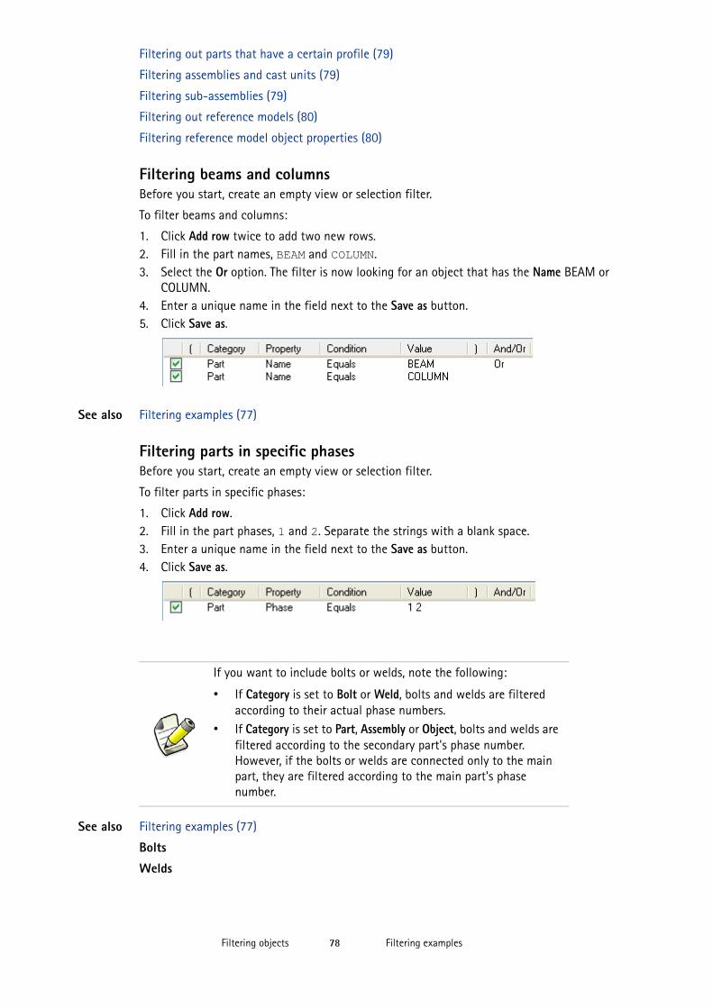
Filtering examplesFiltering objects 78
Filtering out parts that have a certain profile (79)
Filtering assemblies and cast units (79)
Filtering sub-assemblies (79)
Filtering out reference models (80)
Filtering reference model object properties (80)
Filtering beams and columnsBefore you start, create an empty view or selection filter.
To filter beams and columns:
1. Click Add row twice to add two new rows. 2. Fill in the part names, BEAM and COLUMN.3. Select the Or option. The filter is now looking for an object that has the Name BEAM or
COLUMN.4. Enter a unique name in the field next to the Save as button.5. Click Save as.
See also Filtering examples (77)
Filtering parts in specific phasesBefore you start, create an empty view or selection filter.
To filter parts in specific phases:
1. Click Add row. 2. Fill in the part phases, 1 and 2. Separate the strings with a blank space.3. Enter a unique name in the field next to the Save as button.4. Click Save as.
See also Filtering examples (77)
Bolts
Welds
If you want to include bolts or welds, note the following:
• If Category is set to Bolt or Weld, bolts and welds are filtered according to their actual phase numbers.
• If Category is set to Part, Assembly or Object, bolts and welds are filtered according to the secondary part's phase number. However, if the bolts or welds are connected only to the main part, they are filtered according to the main part's phase number.
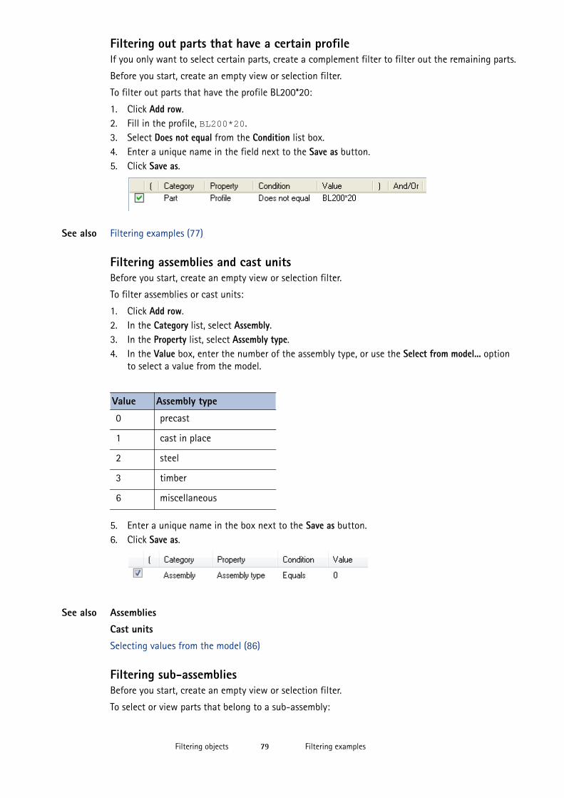
Filtering examplesFiltering objects 79
Filtering out parts that have a certain profileIf you only want to select certain parts, create a complement filter to filter out the remaining parts.
Before you start, create an empty view or selection filter.
To filter out parts that have the profile BL200*20:
1. Click Add row. 2. Fill in the profile, BL200*20.3. Select Does not equal from the Condition list box.4. Enter a unique name in the field next to the Save as button.5. Click Save as.
See also Filtering examples (77)
Filtering assemblies and cast unitsBefore you start, create an empty view or selection filter.
To filter assemblies or cast units:
1. Click Add row.2. In the Category list, select Assembly.3. In the Property list, select Assembly type.4. In the Value box, enter the number of the assembly type, or use the Select from model... option
to select a value from the model.
5. Enter a unique name in the box next to the Save as button.6. Click Save as.
See also Assemblies
Cast units
Selecting values from the model (86)
Filtering sub-assembliesBefore you start, create an empty view or selection filter.
To select or view parts that belong to a sub-assembly:
Value Assembly type
0 precast
1 cast in place
2 steel
3 timber
6 miscellaneous
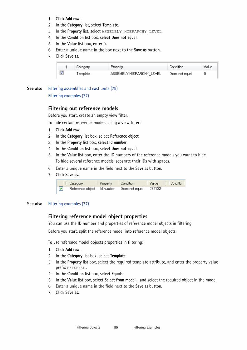
Filtering examplesFiltering objects 80
1. Click Add row.2. In the Category list, select Template.3. In the Property list, select ASSEMBLY.HIERARCHY_LEVEL. 4. In the Condition list box, select Does not equal.5. In the Value list box, enter 0.6. Enter a unique name in the box next to the Save as button.7. Click Save as.
See also Filtering assemblies and cast units (79)
Filtering examples (77)
Filtering out reference modelsBefore you start, create an empty view filter.
To hide certain reference models using a view filter:
1. Click Add row. 2. In the Category list box, select Reference object.3. In the Property list box, select Id number.4. In the Condition list box, select Does not equal.5. In the Value list box, enter the ID numbers of the reference models you want to hide.
To hide several reference models, separate their IDs with spaces.
6. Enter a unique name in the field next to the Save as button.7. Click Save as.
See also Filtering examples (77)
Filtering reference model object propertiesYou can use the ID number and properties of reference model objects in filtering.
Before you start, split the reference model into reference model objects.
To use reference model objects properties in filtering:
1. Click Add row.2. In the Category list box, select Template.3. In the Property list box, select the required template attribute, and enter the property value
prefix EXTERNAL .4. In the Condition list box, select Equals.5. In the Value list box, select Select from model... and select the required object in the model.6. Enter a unique name in the field next to the Save as button. 7. Click Save as.
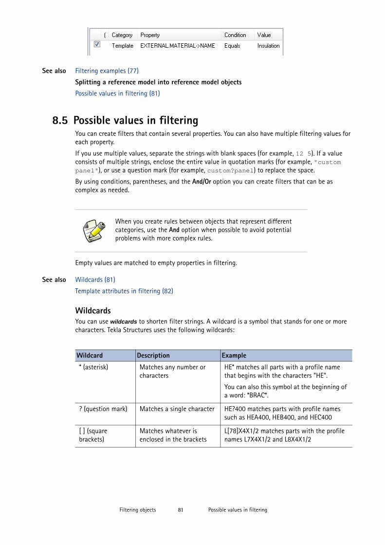
Possible values in filteringFiltering objects 81
See also Filtering examples (77)
Splitting a reference model into reference model objects
Possible values in filtering (81)
8.5 Possible values in filteringYou can create filters that contain several properties. You can also have multiple filtering values for each property.
If you use multiple values, separate the strings with blank spaces (for example, 12 5). If a value consists of multiple strings, enclose the entire value in quotation marks (for example, "custom panel"), or use a question mark (for example, custom?panel) to replace the space.
By using conditions, parentheses, and the And/Or option you can create filters that can be as complex as needed.
Empty values are matched to empty properties in filtering.
See also Wildcards (81)
Template attributes in filtering (82)
WildcardsYou can use wildcards to shorten filter strings. A wildcard is a symbol that stands for one or more characters. Tekla Structures uses the following wildcards:
When you create rules between objects that represent different categories, use the And option when possible to avoid potential problems with more complex rules.
Wildcard Description Example
* (asterisk) Matches any number or characters
HE* matches all parts with a profile name that begins with the characters "HE".
You can also this symbol at the beginning of a word: *BRAC*.
? (question mark) Matches a single character HE?400 matches parts with profile names such as HEA400, HEB400, and HEC400
[ ] (square brackets)
Matches whatever is enclosed in the brackets
L[78]X4X1/2 matches parts with the profile names L7X4X1/2 and L8X4X1/2
Copying a filter to another modelFiltering objects 82
See also Possible values in filtering (81)
Template attributes in filtering
You can select objects according to template attributes. To do this, select Template from the Category list box, and then select the desired template attribute from the Property list box.
Use the following units when filtering template attributes, even when using the US Imperial environment:
• mm for length
• mm2 for area
• kg for weight• degree for angle
See also Possible values in filtering (81)
8.6 Copying a filter to another modelTo copy a filter to another model:
1. Select the filter you want to copy.The filters you have created are located in the model’s attributes folder. View filters have the file name extension *.VObjGrp, and selection filters have the file name extension *.SObjGrp.
2. Select where you want to copy the filter.• To make the filter available in another model, copy the file to the attributes folder of
the destination model.• To make the filter available in all models, copy the file to the system folder.
3. Restart Tekla Structures.
See also Filtering objects (73)
The characters * and ? can also be used in object names. If the object name you want to filter contains * or ?, enclose * or ? in square brackets. For example, to find the profile P100*10, enter P100[*]10 in the filter field.
This section is for advanced users.
To check which unit Tekla Structures uses for a particular template attribute, use the Select from model... option in the Value list box.
Deleting a filterFiltering objects 83
8.7 Deleting a filterTo delete a filter:
1. Delete the filter file located in the model’s attributes folder.View filters have the file name extension *.VObjGrp, and selection filters have the file name extension *.SObjGrp.
2. Restart Tekla Structures.
See also Filtering objects (73)

Deleting a filterFiltering objects 84
Modifying one property in several parts at the same timeTips for basic tasks 85
9 Tips for basic tasks
This section provides useful hints and tips that help you use the Tekla Structures user interface and its basic features more efficiently.
Contents Modifying one property in several parts at the same time (85)
Copying and moving efficiently (85)
Selecting values from the model (86)
Copying Mini Toolbar settings to another computer (86)
9.1 Modifying one property in several parts at the same timeYou can quickly change one property in same type of parts at the same time.
To modify one property in several parts at the same time:
1. Double-click a part to open the properties dialog box.2. Click the switch on/switch off button to clear all selections from the check boxes next to the
properties.3. Select the check box next to the property that you want to change, for example Class.4. Change the Class value.
Leave the dialog box open.
5. Select all parts the Class of which you want to change.6. Click Modify in the part properties dialog box.7. Click Cancel to close the dialog box.
9.2 Copying and moving efficientlyYou can keep the Move and Copy dialog boxes open if you are going to use them often, for example, when creating grids and levels in a new model.
To keep a dialog box open while modeling:
1. Start the Move or Copy command.2. To stop copying or moving objects, right-click and select Interrupt from the pop-up menu.
The dialog box remains open on the screen.
3. To continue copying or moving objects:a Click the dialog box to activate it.b Select an object.
Selecting values from the modelTips for basic tasks 86
c Enter the values you want to use, and then click the Move or Copy button in the dialog box.
See also Copying and moving objects (45)
9.3 Selecting values from the modelYou can select object properties and dates directly from the model. This can be useful when creating view filters, selection filters, and object groups.
Before you start, create an empty view or selection filter, or an object group.
To select values from the model:
1. Click Add row.2. Select options from the Category and Property list boxes.3. In the Value list box, select one of the options.
The availability of options depends on your selection in the Property list box. You can select dates from the model only if the property is a date.
a To select an object property, click Select from model... and then select an object.b To select a date, click Select date... to open the Select date dialog box, and then select
one of the options.You can either select a date from the calendar, select the review date, or define the number of days before or after the review date. The review date is the same as Review date in the Project Status Visualization dialog box.
See also Creating a view filter (73)
Creating a selection filter (75)
Creating an object group
Creating a visualization
9.4 Copying Mini Toolbar settings to another computerAfter customizing the Mini Toolbar, you can copy the settings to another computer. This can be useful, for example, when you want to ensure that everyone in your company uses the same settings. A settings file is saved onto your computer the first time you customize the Mini Toolbar.
To copy Mini Toolbar settings:
1. Locate the teklastructures.minitoolbar.xml file on your computer.2. Copy the file to the appropriate location on the other computer.
See also Customizing the Mini Toolbar (18)
Location of hidden files
This section is for advanced users.
Index
87
aarea selection.....................................................................39assemblies
assembly types in filtering .....................................79nested assemblies .....................................................41selecting ......................................................................41
assigningkeyboard shortcuts ...................................................25
bbasics of Tekla Structures
tips ................................................................................85bolts
filtering ........................................................................78buttons
common buttons.......................................................20Load ..............................................................................20Save ..............................................................................20Save as .........................................................................20
ccast units
selecting ......................................................................41commands...........................................................................29
ending ..........................................................................30redoing.........................................................................30repeating .....................................................................30running ........................................................................29undoing........................................................................30
common commandskeyboard shortcuts ...................................................31
componentsselecting ......................................................................41
configurations....................................................................10coordinates
absolute .......................................................................68input options..............................................................68locking..........................................................................66relative .........................................................................68
copyingby specifying distance from origin ...................... 47drawing objects......................................................... 46filters ............................................................................ 82from another model ................................................. 49hints and tips ............................................................. 85keyboard shortcuts................................................... 56linearly to new position.......................................... 47objects.................................................................. 45, 46to another object...................................................... 48to another plane ....................................................... 48using drag-and-drop ............................................... 48
creatingobjects.......................................................................... 33selection filters.......................................................... 75view filters .................................................................. 73
crossing selection ............................................................. 39customizing
toolbars........................................................................ 18user interface............................................................. 24
ddialog boxes ....................................................................... 18
common buttons....................................................... 20common elements .................................................... 18entering information ............................................... 18loading saved properties......................................... 21saving properties....................................................... 21tabs ............................................................................... 19
drag-and-drop........................................................... 48, 51drawing filters ................................................................... 75
creating ....................................................................... 76drawing objects
copying ........................................................................ 46mirroring ..................................................................... 55moving ......................................................................... 49rotating................................................................ 52, 55
drawingscreating drawing filters .......................................... 76creating view filters ................................................. 76
duplicate objects............................................................... 45
88
eenhanced tooltips .............................................................21entering information in dialog boxes .........................18environments .....................................................................12examples
filtering beams and columns.................................78filtering out reference models ..............................80filtering parts in specific phases ..........................78filtering parts with certain profile .......................79snapping in drawings...............................................69
exiting Tekla Structures ..................................................15extension lines...................................................................63
ffeatures.................................................................................. 9filtering
assemblies...................................................................79bolts and welds .........................................................78cast units.....................................................................79copying filters ............................................................82deleting filters ...........................................................83examples............................................... 77, 78, 79, 80objects..........................................................................73possible values...........................................................81reference model objects properties .....................80selection filters.................................................. 74, 75sub-assemblies ..........................................................79using template attributes.......................................82view filters ..................................................................73wildcards .....................................................................81
filtersin drawings .................................................................75in views........................................................................75selection ......................................................................38
hhandles
selecting ......................................................................40hiding
dimensions..................................................................37reference models.......................................................80toolbars........................................................................16tooltips.........................................................................21
highlightingselectable objects .....................................................38
iinterrupting
commands...................................................................30object selection .........................................................43
introduction to Tekla Structures .....................................9
kkeyboard shortcuts
assigning ..................................................................... 25for common commands .......................................... 31for copying and moving objects ........................... 56for selecting objects ................................................ 43for snapping ............................................................... 71
llanguages
available languages.................................................. 11changing the language of user interface .......... 11
large icons .......................................................................... 26licences ................................................................................ 10linear
copying ........................................................................ 47moving ......................................................................... 50
loading dialog box properties ....................................... 21locking Mini Toolbar ........................................................ 17locking the pointer in a direction ................................ 66
mmenu tooltips..................................................................... 21menus
creating user-defined menus ................................ 25Mini Toolbar ....................................................................... 17
changing the position and distance.................... 17copying settings to another computer ............... 86customizing ................................................................ 18locking the position ................................................. 17
mirroringdrawing objects......................................................... 55objects.......................................................................... 55
modifyingproperties in many parts simultaneously........... 85
movingby specifying distance from origin ...................... 50drawing objects......................................................... 49hints and tips ............................................................. 85keyboard shortcuts................................................... 56linearly to new position.......................................... 50objects.................................................................. 45, 49to another object...................................................... 52to another plane ....................................................... 51toolbars........................................................................ 16using drag-and-drop ............................................... 51
multi-user vs single-user................................................ 12
89
nnested assemblies .............................................................41
oobjects
copying ................................................................ 45, 46creating........................................................................33deleting........................................................................34duplicates....................................................................45extension lines...........................................................63filtering ........................................................................73mirroring .....................................................................55modifying ............................................................ 33, 34moving ................................................................. 45, 49rotating........................................................................52selecting .............................................................. 37, 39
orthogonal directions .............................................. 61, 62overriding snap switches ................................................61
pparts
filtering ........................................................................78modifying properties................................................85tips ................................................................................85
phasesfiltering ........................................................................78
picking points, see snapping..........................................57pinning Mini Toolbar........................................................17points
picking, see snapping...............................................57profiles
filtering ........................................................................79prompts................................................................................23
rredoing commands ...........................................................30reference model objects
selecting ......................................................................42reference models
filtering ........................................................................80selecting ......................................................................42
reference points ................................................................65repeating commands .......................................................30roles ......................................................................................10rollover highlight ..............................................................38rotating
around a line ..............................................................52around z axis ..............................................................53drawing objects................................................. 52, 55objects..........................................................................52
running commands .......................................................... 29
ssaving
dialog box properties............................................... 21selecting
adding objects to selection.................................... 42assemblies................................................................... 41cast units..................................................................... 41crossing window selection..................................... 39dates from model...................................................... 86handles ........................................................................ 40interrupting object selection................................. 43keyboard shortcuts................................................... 43modifying selection.................................................. 42multiple objects ........................................................ 39nested assemblies..................................................... 41objects.................................................................. 37, 38objects in components ............................................ 41reference model objects ......................................... 42reference models ...................................................... 42single objects ............................................................. 39values from model.................................................... 86window selection...................................................... 39
selection filters...................................................38, 74, 75selection switches ............................................................ 38showing
dimensions.................................................................. 37toolbars................................................................ 16, 61tooltips......................................................................... 21warning messages .................................................... 23
single-user vs multi-user................................................ 12Smart Select....................................................................... 51snap switches .................................................................... 58
main snap switches.................................................. 59other snap switches ................................................. 60overriding.................................................................... 61
snappingdimensions.................................................................. 57in orthogonal directions ......................................... 61keyboard shortcuts................................................... 71relative to previously picked points..................... 62snap depth .................................................................. 58snap grids.................................................................... 70snap override.............................................................. 61snap priority ............................................................... 58snap symbol................................................................ 57snap zone.................................................................... 58snapping toolbar....................................................... 58to extension lines ..................................................... 63to line........................................................................... 62to positions at even distances ...................... 61, 63using coordinates ............................................. 66, 69
90
using temporary reference points ........................65using tracking ............................................................67
starting Tekla Structures ................................................15status bar ............................................................................23sub-assemblies
filtering ........................................................................79switching between
tabs ...............................................................................19
ttabs .......................................................................................19template attributes
in filtering ...................................................................82temporary reference points............................................65tips
copying and moving efficiently ............................85copying Mini Toolbar settings...............................86selecting values from model..................................86
toolbars................................................................................16changing the size of buttons.................................26creating toolbars of your own ..............................24Mini Toolbar ...............................................................17moving .........................................................................16selection switches ....................................................38
tooltips.................................................................................21tracking................................................................................67
uundoing commands.......................................................... 30user interface
customizing ................................................................ 24languages.................................................................... 11overview ...................................................................... 15
vvalues
selecting from model............................................... 86view filters .................................................................. 73, 75
creating ....................................................................... 76
wwarning messages ............................................................ 23welds
filtering........................................................................ 78wildcards ............................................................................. 81window selection.............................................................. 39work area
objects outside the work area............................... 23