Embed Size (px)
Citation preview

Subject to change 1� Internet: www.festo.com/catalogue/...
Basic principles of vacuum technology, brief overviewIntroduction
Basic principles of vacuum technology
What is a vacuum? Vacuum ranges Units of measurement
A vacuum is a space entirely devoid of
matter (“absolute vacuum”).
In practice we talk about a vacuum
when the air pressure in a space lies
below atmospheric pressure.
GV
FV
HV
UHV
P
[pa]
P
[mbar]There are a large number of national
and international units of
measurement. The most commonly
used units are Pascal (Pa) and bar
100 Pa = 1 hPa
1 hPa = 1 mbar
1 mbar = 0.001 bar
The vacuum level is often expressed
as a % value. However, these are
always relative values.
GV = Rough vacuum
FV = Medium vacuum
HV = High vacuum
UHV = Ultra-high vacuum
What is a vacuum used for? Measuring the pressure or vacuum Atmospheric pressure
The vacuum plays a vital role in
research in the fields of chemistry,
biology and physics.
It is also indispensable in many
industrial processes.
In the rough vacuum range, the
pressure gauges used are mainly
mechanical, but some digital pressure
gauges are also used.
In the high and ultra-high vacuum
range, highly sensitive pressure
gauges are used.
h [km]
p [hPa]
1 Mount Everest
2 Festo
3 Sea level
Understanding vacuum Vacuum specification options Effects of changes on vacuum
technology
Air is a gas mixture with approx.
1025 particles per m3 of air at one bar
air pressure.
Particles exert pressure or force on the
walls of a defined space. The fewer
particles there are in the space, the
lower the force exerted on the walls.
A vacuum can be specified as an
absolute value, i.e. with a positive
sign from 1 to 0 bar, with 0 as
absolute zero. Or it can be specified
as a relative value with a negative
sign from 0 to –1 bar, with 0 as a
reference point, or as a %.
As altitude increases, the air pressure
in the atmosphere falls. This same
effect reduces the attainable vacuum
level of an ejector. Nevertheless, the
performance level of 80% remains
unchanged in this case.
Pressure =ForceArea
100% vacuum would mean that there
are no particles present. Pressure = 0.

Subject to change2 � Internet: www.festo.com/catalogue/...
Basic principles of vacuum technology, brief overviewIntroduction
Components for vacuum generation
Vacuum ejectors Displacement vacuum pumps Kinetic vacuum pumps
These function according to the
venturi principle, i.e. they are driven
purely pneumatically and have a
much simpler design compared with
other vacuum generators.
Air flowing into a space is
mechanically shut off, compressed
and ejected. This allows a very high
vacuum to be achieved at a very low
flow rate.
Air is forced to flow in the delivery
direction through the application of
additional mechanical force. This
method achieves only a relatively low
vacuum level despite a high suction
rate.
Principle
• The most important components
are the jet nozzle (venturi nozzle)
and at least one receiver nozzle.
• Accelerated compressed air
generates a suction effect between
both nozzles (vacuum).
• There are different design
principles: single-stage and multi-
stage ejectors.
• Depending on the principle, air is
either carried away in a flow by a
rotating impeller on the suction
side or compressed using vaned
chambers.
• The pump types available
include vacuum blowers and
vacuum compressors, for example.
1
2
3
4
5
1 Pressure side
2 Suction side
3 Inlet valve
4 Exhaust valve
5 Piston
Features
• High vacuum level with relatively
small flow rate
• Maintenance-free and wear-free
• Low-cost
• Low-weight, compact design
• Any mounting position
• High vacuum level up to –0.98 bar
operating pressure
• Minimal maintenance expenses
• Generally large dimensions and
high weight
• Restricted mounting position
• Large flow rates, low vacuum level
• High maintenance costs
Application
• Wide range of applications,
e.g. handling technology and
process engineering.
• Broad application spectrum in
industry and research.
• Used mainly for precision processes
in industry.

Subject to change 3� Internet: www.festo.com/catalogue/...
Basic principles of vacuum technology, brief overviewIntroduction
Vacuum in handling technology
Practical use of vacuum Important selection factors Benefits of a vacuum
The extensive range of vacuum
component variants makes them ideal
for use in many industrial
applications.
Loading
Lifting Conveyance
Turning
Machining
Holding
Insertion
Transporting
Feeding Repositioning
Moving
Gripping
• Weight, temperature, shape and
roughness of the workpiece surface
• Speed per unit of time
• Stroke travel and conveying
distances
• Gentle handling
• Compact, low-weight, space-saving
design
• Fast cycle times possible
• Low maintenance costs
• Low-cost
Comparison of ejectors
Variables/criteria Single-stage Multi-stage
Suction flow rate Average High
At low vacuum level up to approx. 50%
Evacuation time Very short
In higher vacuum range from 30 … 50%
Very short
In lower vacuum range up to 30 … 50%
Initial costs Low Relatively high
Noise generation Relatively high Low
Both principles have their advantages
and disadvantages which are difficult
to compare. With optimally adapted
components, both principles can
cover a large number of different areas
of application.
Important comparison variables
Evacuation time Air consumption Efficiency Suction flow rate
Evacuation time = Time (s) required to
generate a specific vacuum.
Air consumption = Air consumption
(l/min) of the ejector required to
generate a specific vacuum.
The efficiency formula makes it easier
to compare the different principles:
Efficiency = Evacuation time, air
consumption and volume dependent
on vacuum.
The efficiency of an ejector is often –
and incorrectly – measured using the
suction flow rate at 0 bar.
Suction flow rate = Suction air volume
(l/min) that an ejector can draw in.

Subject to change4 � Internet: www.festo.com/catalogue/...
Basic principles of vacuum technology, brief overviewIntroduction
Vacuum in handling technology
Energy cost comparison
To generate compressed air from
atmospheric air, you need to reckon
on approx. € 0.02 per m3 volume at
7 bar pressure when calculating the
costs involved (e.g. investment,
material, labour, etc.).
Vacuum ejectors:
• High air consumption, but
compensated by its energy-saving
function
• Maintenance-free, no moving parts
• Low weight and component
dimensions and can be installed in
any mounting position
• No electrical connections required
• Relatively high vacuum level (up to
85% vacuum) attainable
• Low initial costs
Electric vacuum pumps:
• Very high vacuum (up to 99.99%)
attainable
• High suction rates (vacuum blower)
of up to 1,200 m3/hr. possible
• High current consumption because
of continuously operated pumps
• High initial costs and ongoing
maintenance costs
• Large weight and unit volume as
well as fixed mounting position
For a comparison of features, a
calculation example and an energy
cost comparison� following
sections.
Leakage in vacuum systems
When a vacuum suction gripper
cannot fully seal the system against
atmospheric air, we talk about leaking
systems.
This might be caused, for example, by
rough and uneven workpiece surfaces
or air-permeable workpiece materials.
Remedial actions to achieve the
required vacuum:
• Use of high-performance ejectors
• Reduction of the suction cup
diameter
Selection aid for vacuum generators
In all cases, it is recommended that
you perform a test setup to determine
the leak rate, thereby enabling you to
ascertain which vacuum ejector you
need.
Procedure:
• Determining the leak rate
– Perform the test setup
– Read the vacuum value achieved
– Compare the result with the
course of the curve in the
‘Suction capacity as a function of
vacuum’ chart (� 28)
– Difference with respect to suction
capacity = leak rate
• Determining the correct ejector size
– Intersection of the leak rate (now
known) with the curves of other
ejectors
– Determine the attainable vacuum
by means of projecting
downwards from the
intersections with the leak rate
• Select the ejector that reaches the
required vacuum level.

Subject to change 5� Internet: www.festo.com/catalogue/...
Basic principles of vacuum technology, brief overviewIntroduction
Typical applications

Subject to change6 � Internet: www.festo.com/catalogue/...
Basic principles of vacuum technologyIntroduction
What is a vacuum?
In physics, a vacuum is defined as
“a state of emptiness that can be
achieved by experiment” – in other
words, nothing.
This definition refers to the state of a
space entirely devoid of matter
(sometimes also referred to as an
“absolute vacuum”).
In practice, however, this state cannot
be achieved. We therefore talk instead
about a vacuum when the air pressure
in a space is lower than the
atmospheric pressure or when the
density of air molecules is reduced.
Furthermore, every space contains
particles of matter such as protons
and electrons, as well as zero-mass
particles – photons – which transport
energy at the speed of light.
What is a vacuum used for?
Since the 17th century (“Magdeburg
hemispheres”) mankind has been
studying vacuum. Today, we cannot
imagine modern research without it.
In chemistry, reactions in substances
are investigated in a vacuum, biology
is interested in the effects of a
vacuum on organisms, while some
areas of physics (quantum physics,
field theory, etc.) are concerned with
particles that can be examined more
accurately in a vacuum.
Today, the vacuum plays a vital role in
important industrial processes, many
of which would not be possible
without it. Noteworthy examples
include semiconductor manufacture
or mass spectroscopy.
Vacuum technology has also played a
part in the development and
implementation of new ideas in
handling technology, i.e. lifting,
holding, rotating and transporting all
kinds of parts.
Understanding vacuum
Air is a gas mixture containing
approx. 1025 particles per m3 at
one bar air pressure.
In the atmosphere, this gas mixture is
made up of the following gases and
proportions:
78% Nitrogen
21% Oxygen
1% Other gases
(e.g. carbon dioxide and
argon)
Nitrogen
Oxygen
Other gases
To attain a state of vacuum, a space
must be empty, i.e. devoid of all
gaseous material.
The consequence of this is that the
pressure in this space is very low, as it
contains no or only a small number of
particles, which exert a force on an
area as a result of their impact
against the walls.
Pressure is therefore defined as
follows:
In theory, in an absolute vacuum,
i.e. where there are no more particles
of matter in the space, pressure = 0.
Pressure =ForceArea
Pressure gauge
Small number of particles
at constant temperature
� low pressure
Pressure gauge
Large number of particles
at constant temperature
� high pressure
In reality, however, this is rarely
achievable. In an ultra-high vacuum,
the pressure may indeed be low
(approx. 10–8 to 10–11mbar), but the
particle number density is still
approx. 2.5 x 10¹³ particles per m3.
The following rule therefore applies:
The fewer particles there are, the
lower the pressure.

Subject to change 7� Internet: www.festo.com/catalogue/...
Basic principles of vacuum technologyIntroduction
Vacuum ranges
In practice, the large vacuum range
that can technically be achieved –
which now consists of more than
16 powers of ten – is generally
subdivided into smaller ranges.
The vacuum ranges below are
classified according to physical
attributes and technical
requirements.
FV
HV
UHV
P
[pa]
P
[mbar]
GVHandling range:
This vacuum range is used in handling
technology.
GV = Rough vacuum
FV = Medium vacuum
HV = High vacuum
UHV = Ultra-high vacuum
Vacuum range Pressure range (absolute) Applications
Rough vacuum Atmospheric pressure … 1 mbar Applications in industrial handling technology.
In practice, the vacuum level is often specified as a percentage, i.e. the vacuum
is defined in proportion to its ambient pressure. The material and the surface
finish of workpieces play a major role in vacuum applications.
Medium vacuum 10–3 … 1 mbar Steel degassing, light bulb production, drying of plastics, freeze drying of
foodstuffs, etc.
High vacuum 10–3 … 10–8 mbar Smelting or annealing of metals, electron tube manufacture.
Ultra-high vacuum 10–8 … 10–11 mbar Spraying of metals, vacuum metallizing (coating of metals) as well as electron
beam melting.
Measuring the pressure or vacuum
Pressure is defined as the force per
unit area. Air is a gas mixture made
up of many particles (atoms and
molecules). These particles are in
continuous motion. Wherever they
meet, they exert a force.
The pressure and vacuum are
measured by taking a specific unit
area and measuring the number and
intensity of this impact on this area.
Measurements are necessary in order
to be able to check and monitor
processes.
For this reason, all measuring
instruments must be “calibrated”,
i.e. individual measuring instruments
with the same function must be
adjusted so that they produce the
same result under the same
conditions.
In order to be able to evaluate or
measure the vacuum medium, there
are a number of items of technical
equipment that are indispensable for
applications in the fields of industry
and research.
Pressure gauges (vacuum gauges) are
used generally as well as in the rough
vacuum range. These gauges are
scaled according to the level of
accuracy required. Pressure gauges
work according to many different
operating principles and can function
mechanically or digitally.
The most common mechanical
function types are:
• Bourdon tube pressure gauge
• Aneroid pressure gauge
• Diaphragm pressure gauge
• Digital pressure gauge
In the high and ultra-high vacuum
range, pressure gauges with highly
sensitive response mechanisms are
used. A great many additional factors
play a role in determining the
measurement results in this case.
It is important to remember that there
are two different options for specifying
or representing the same
measurement result.
1 Bourdon tube
2 Spring support
3 Spring end piece
4 Segment
5 Tie rod
6 Gearing
7 Indicator shaft
8 Coil spring
9 Indicator
aJ Dial face

Subject to change8 � Internet: www.festo.com/catalogue/...
Basic principles of vacuum technologyIntroduction
Vacuum designations and specification options
It is important to mention at this point
that there a number of different
designations for the term vacuum in
both colloquial and technical
language.
In order to avoid any uncertainty or
misunderstanding, these designations
need to be explained here.
Vacuum
Correct designation – specified as %
only in the range 0 … 1 bar absolute
pressure.
Operating pressure Vacuum as an absolute value Vacuum as a relative value
Correct designation, operating
pressure of 0 bar relative pressure is
equivalent to 1 bar absolute pressure.
A vacuum is generally specified as
relative operating pressure, i.e. with a
negative sign.
Operating pressure can be specified
correctly in two different ways, i.e. as
a relative or an absolute value. Both
specification options are also applied
to vacuums and are explained in more
detail below.
Applications:
In the field of science as well as in the
medium-high and high vacuum
ranges.
Principle:
Vacuum is specified as an absolute
value in proportion to absolute zero,
i.e. 0 bar is the lowest value and
corresponds to 100% vacuum. In the
vacuum range, 1 bar is thus the
highest value and corresponds to the
average ambient pressure.
Feature:
Vacuum values have positive signs.
Vacuum range 1 … 0 bar
Applications:
In the rough or operating vacuum
range (e.g. for Festo applications).
Principle:
Vacuum is specified as a relative
value in proportion to ambient
pressure, i.e. the specified vacuum
value has a negative sign, because
the ambient pressure (atmospheric
pressure) has been assumed as the
reference point with a value of 0. The
lowest value, i.e. also 100% vacuum
corresponds to –1 bar relative
operating pressure.
Feature:
Vacuum values have negative signs.
Vacuum range 0…-1 bar
Specification options for the pressure or vacuum
Operating pressure Vacuum Absolute pressure
[bar] [%] [bar]
6 – 7
5 6
4 5
3 4
2 3
1 2
0 0 1
–0.1 10 0.9
–0.2 20 0.8
–0.3 30 0.7
–0.4 40 0.6
–0.5 50 0.5
–0.6 60 0.4
–0.7 70 0.3
–0.8 80 0.2
–0.85 85 0.15
–0.9 90 0.1
–0.95 95 0.05
–1 100 0

Subject to change 9� Internet: www.festo.com/catalogue/...
Basic principles of vacuum technologyIntroduction
Units of measurement
As already described in the section
“Designations and specification
options”, there are two ways of
representing a vacuum:
• As a pressure unit
(relative or absolute)
• As a percentage
There are a large number of national
and international units of
measurement in common use that can
be used to specify a vacuum as a
pressure unit.
These units of measurement are listed
in the conversion table (international
vacuum/pressure conversion table)
below.
It should be mentioned here that the
current official unit of measurement
for the vacuum is the pascal (Pa).
However, this is rarely used in
practice. In reality, the preferred units
of measurement are bar, mbar or %,
particularly in the rough vacuum
range (e.g. handling technology).
In the following pages also, only the
units of measurement bar and % are
used.
Vacuum specifications that use bar as
the unit of measurement are always
considered as relative values
(described under “Vacuum as a
relative value”).
The most commonly used pressure
units bear the following ratios to one
another:
100 Pa = 1 hPa
1 hPa = 1 mbar
1 mbar = 0.001 bar
For the sake of simplicity, vacuum is
generally expressed as a percentage
in the range 0 to 100%.
This is always a relative value.
The conversion tables (international
vacuum/pressure conversion tables)
below are a useful aid for expressing
these values relative to the other units
of measurement.
International vacuum/pressure conversion table
Unit bar N/cm2 kPa atm, kp/cm2 m H2O torr, mm Hg in Hg psi
bar 1 10 100 1.0197 1.0197 750.06 29.54 14.5
N/cm2 0.1 1 10 0.1019 0.1019 75.006 2.954 1.45
kPa 0.01 0.1 1 0.0102 0.0102 7.5006 0.2954 0.145
atm, kp/cm2 0.9807 9.807 98.07 1 1 735.56 28.97 14.22
m H2O 0.9807 9.807 98.07 1 1 735.56 28.97 14.22
torr, mm Hg 0.00133 0.01333 0.1333 0.00136 0.00136 1 0.0394 0.0193
in Hg 0.0338 0.3385 3.885 0.03446 0.03446 25.35 1 0.49
psi 0.0689 0.6896 6.896 0.0703 0.0703 51.68 2.035 1
International vacuum/pressure conversion table with absolute and relative value comparison
Relative vacuum Residual
pressure,
absolute
Pressure,
relative
N/cm2 kPa atm, kp/cm2 m H2O torr, mm Hg in Hg
[%] [bar] [bar]
10 0.9 –0.101 –1.01 –10.1 –0.103 –0.103 –76 –3
20 0.8 –0.203 –2.03 –20.3 –0.207 –0.207 –152 –6
30 0.7 –0.304 –3.04 –30.4 –0.31 –0.31 –228 –9
40 0.6 –0.405 –4.05 –40.5 –0.413 –0.413 –304 –12
50 0.5 –0.507 –5.07 –50.7 –0.517 –0.517 –380 –15
60 0.4 –0.608 –6.08 –60.8 –0.62 –0.62 –456 –18
70 0.3 –0.709 –7.09 –70.9 –0.723 –0.723 –532 –21
80 0.2 –0.811 –8.11 –81.1 –0.827 –0.827 –608 –24
90 0.1 –0.912 –9.12 –91.2 –0.93 –0.93 –684 –27

Subject to change10 � Internet: www.festo.com/catalogue/...
Basic principles of vacuum technologyIntroduction
Atmospheric air pressure
Definition
Our planet – which includes us as
well as everything on the earth’s
surface – is surrounded by a layer of
air several kilometres thick. This layer
of air is known as the earth’s
atmosphere or, more simply, the
atmosphere. Gravity causes the
weight of this mass of air to exert
pressure on the earth’s surface.
The pressure generated is known as
atmospheric pressure or air pressure.
Our atmospheric conditions can also
be compared with conditions under
water. We live at the bottom of a “sea
of air”.
The gravitational force of the air above
us generates pressure which we call
air pressure.
At present, the official unit of
measurement for air pressure is hPa.
This abbreviation stands for
hectopascal (1 hPa = 1 mbar).
On average, the air pressure at sea
level is 1,013.25 mbar. If we imagine
an air column with a cross-section
area of 1 m2, which extends from the
earth’s surface (sea level) to the
outermost edge of the atmosphere,
the air exerts pressure on this 1 m2 of
the earth’s surface with a mass
of 10,000 kg approx.
If, starting at sea level, we now begin
to climb higher, this imaginary air
column becomes shorter and the air
mass is reduced. Because the air
pressure falls as the air mass
decreases, we can conclude that
atmospheric air pressure falls as
altitude increases. This is why we say
that “the air is getting thinner”.
Air pressure dependent on altitude
can be calculated using the
Boltzmann barometric equation. This
calculation is affected by a wide
variety of factors.
In order to achieve accurate results, it
is important to consider not only the
output altitude, but also factors such
as local gravitational force,
atmospheric density and
temperature.
To make things simpler, the air
temperature and mass are considered
as constants when deriving the
formula.
In the derivation of the formula, the
density of the layer of air (ρ) as well as
the pressure at the earth’s surface
(p(h=0)) are based on assumptions
from empirical values.
These courses of action and
simplification of the formula
derivation are an idealisation.
p(h) = Air pressure dependent
on altitude
p(h = 0) = Pressure at the earth’s
surface (1.013 bar)
ρ = Density of the layer of air
(1.29 kg/m3)
h = Altitude
g = Acceleration due to
gravity
p(h) = p(h=0)exp�− �× ghp(h=0)
�-H- Note
NASA describes an altitude of
approx. 120 km above the earth’s
surface as the outermost edge of the
atmosphere. Air molecules can,
however, be found at much greater
altitudes. It is therefore impossible
to definitively identify the “edge” of
the atmosphere.
Generally applicable statements
• At sea level, atmospheric pressure
is approx. 1,013 mbar.
• By 2,000 m above sea level, the
pressure has fallen by approx. 1%
per 100 m to 763 mbar.
• At approx. 5,500 m, the pressure is
only 50% of the value at sea level.
• At the summit of Mount Everest
(8,848 m), atmospheric pressure is
only 330 mbar.
• At an altitude of 16,000 m the
pressure is 90 mbar, while it is
15 mbar at 30,000 m and approx.
8 mbar at 50,000 m.
h [km]
p [hPa]
1 Mount Everest
2 Festo
3 Sea level

Subject to change 11� Internet: www.festo.com/catalogue/...
Basic principles of vacuum technologyIntroduction
Effect of changes in air pressure on vacuum technology
The pressure drop that occurs with
increasing altitude does, of course,
have an effect on vacuum technology
or even on the vacuum generators
themselves.
Because the air pressure in the
atmosphere falls with increasing
altitude, the maximum attainable
differential pressure and,
consequently, the maximum
attainable holding force of a vacuum
suction gripper are also reduced. In
other words, the attainable vacuum
level of a vacuum ejector reduces with
increasing altitude. Nevertheless, the
performance level of 80% vacuum, for
example, remains unchanged
(� Figure on right).
As described earlier, air pressure at
sea level (0 m) is approx. 1,013 mbar.
At sea level, a vacuum generator with
a performance level of 80% vacuum
achieves absolute pressure of
approx. 0.2 bar (200 mbar).
This air pressure falls with increasing
altitude. Up to a height of 2,000 m,
there is a linear drop in pressure by
approx. 12.5 mbar per 100 m to
763 mbar.
However, although the same vacuum
generator still has the same
performance level of 80% vacuum,
this figure of 80% refers to the
ambient pressure that has fallen to
763 mbar because of the increase in
altitude. This vacuum generator can
therefore only achieve a maximum
absolute pressure of approx.
0.4026 bar (402.6 mbar).
Assuming that we take the same
vacuum generator and go higher than
the previous 2,000 m above sea level
in order to generate or use a vacuum,
the maximum attainable vacuum level
would continue to fall while the
performance level would remain
unchanged at 80% because the
ambient pressure in the atmosphere
continues to drop.
At a height of approx. 5,500 m above
sea level, the air pressure is only
approx. 50% of the pressure value at
sea level (506 mbar).
The possible holding force of a
vacuum suction gripper falls
proportionally with the attainable
vacuum value.
p = Performance of vacuum
generator X = 80%
PB[bar]
PA
[p]
0 m
(sea level)
2,000 mm
(height above
sea level)
1,013 mbar
763 mbar
Valid standards and guidelines
In accordance with Festo standard FN
942 011, the standards and
guidelines have been defined for the
vacuum range.
Vacuum:
All vacuum generators based on this
standard that are covered in this
system description operate exclusively
in the rough vacuum range. In
accordance with the Festo guideline,
the average air pressure at sea
level (1,013.25 mbar) must always be
taken as the reference value when
specifying and calculating pressure
values.
Scaling factor:
When measuring characteristics (air
consumption, pressure, evacuation
time and suction capacity),
fluctuations in the ambient pressure
must be taken into account. Given that
all pressure values measured in the
research laboratory are relative
pressure values referring to the
current ambient pressure, the
fluctuations in ambient pressure
result in a degree of dispersion in the
measurement results.
The measurement results are therefore
related to the reference pressure. They
are converted using a scaling
factor (S), which is calculated on the
basis of the following equation.
(pref = 1,013 mbar)
S =
prefpamb
Example:
A current air pressure
pamb = 975 mbar produces a scaling
factor S = 1.039. The required
vacuum is therefore produced at a
measured value of 750 bar
(0.75 mbar) absolute to P = 780 bar
(0.78 mbar).
DIN standards, research reports and Festo guidelines
DIN 1 314
Pressure, basic definitions and units
DIN 28 400
Vacuum technology
Part 1 General terms
Part 2 Vacuum pumps
Part 3 Vacuum gauges
Part 8 Vacuum systems, components
DIN 28 401
Graphical symbols (summary)
DIN 28 402
Quantities, symbols and units
(summary)
FB 190
Vacuum Guideline – Basic Principles
(Research Report, Festo Research,
Dr. Berger)
FR 970 003
Fluid Units and Variables
FR 970 004
Flow Rate Measurement

Subject to change12 � Internet: www.festo.com/catalogue/...
Basic principles of vacuum technologyIntroduction
Vacuum generator
Introduction
Generating a vacuum in a closed
space means dropping the air or gas
pressure. To do this, the gas particles
must either be removed or reduced in
quantity.
There are basically two ways of doing
this:
1. The gas is evacuated from the
closed space into an external
space or into the atmosphere.
2. The gas is combined within the
vacuum system, i.e. condensed,
absorbed or chemically
combined.
The range of vacuum generators is
very extensive. All work according to
different technical principles and
methods and are often categorised
under the umbrella term “vacuum
pumps”.
We need to categorise the vacuum
generators into three types here and
classify them according to their mode
of operation:
• Vacuum ejectors,
• Gas-absorbing vacuum pumps,
• Gas-feeding vacuum pumps.
A direct comparison of these vacuum
generators would not be objective
enough, as they differ fundamentally
from one another in terms of their
technical construction, their mode of
operation, their ranges of application
and their efficiency.
In this section we will describe the
various types of vacuum generator
referred to here based on their
functionality and focus on their
technical features and benefits.
Vacuum ejector – High vacuum, relatively low flow rate
General
Compared with the often highly
complex and unwieldy mechanical
designs used to generate a vacuum,
the operating principle of ejectors is
extremely simple. Yet despite its
simplicity, this principle offers
enormous potential as an extremely
practical solution.
Vacuum ejectors basically function
according to the venturi nozzle
principle, i.e. the vacuum is generated
using pneumatically driven nozzles
without moving parts.
Vacuum ejectors are characterised by
their ability to generate a high vacuum
or low pressure with a relatively low
flow rate.
They operate according to two different
design principles using very different,
often complex equipment such
as valves, filters, silencers, switches,
etc. However, the crucial element that
they have in common is the fact that
the venturi principle is applied
wherever the vacuum is generated.
Function principle
A classic ejector consists of a jet
nozzle (venturi nozzle) and,
depending on the design principle, at
least one receiver nozzle.
Compressed air enters the ejector. The
narrowing of the jet nozzle (venturi
nozzle) accelerates the air to up to
5 times the speed of sound as it flows
through the jet nozzle.
There is a short gap between the exit
from the jet nozzle and the entry in the
receiver nozzle. The expanded
compressed air from the jet nozzle
creates a suction effect at the gap to
the receiver nozzle, which in turn
creates a vacuum at the output
(vacuum port).
Single-stage ejector
Venturi nozzle
Receiver nozzle
Vacuum port
(jet nozzle)

Subject to change 13� Internet: www.festo.com/catalogue/...
Basic principles of vacuum technologyIntroduction
Vacuum ejector – High vacuum, relatively low flow rate
Design principles
Single-stage ejector:
The design principle for a single-stage
ejector includes a jet nozzle and only
one receiver nozzle. After exiting the
receiver nozzle, the exhaust air is
generally discharged via a silencer or
directly into the atmosphere.
Multi-stage ejector:
This design principle also includes a
jet nozzle. Behind the first receiver
nozzle there are additional nozzle
stages, each of which has a bigger
nozzle diameter in proportion to the
falling air pressure. The drawn-in air
from the first chamber, combined with
the compressed air from the jet
nozzle, is thus used as a propulsion
jet for the other chambers.
Again, the air is generally discharged
via a silencer at the end of the last
receiver nozzle.
Features
• Completely maintenance-free and
wear-resistant because there are no
moving parts
• Low initial costs
• Low energy costs, as the ejector is
only switched on when in use
• No heat build-up
• Compact design, smallest possible
dimensions
• Suitable for pulsed applications
• Fast reacting
• Small line lengths between vacuum
generation and application
• Easy to install, can assume any
mounting position
• Low weight
• Multiple functions possible in a
single device
• Dry and filtered compressed air is
useful
• Supply port 4 … 6 bar optimal
Applications
• Part feeding systems in the
automotive industry
• Packaging industry
• Industrial robot applications in all
sectors
• Process engineering • Transport of liquids and bulk
material

Subject to change14 � Internet: www.festo.com/catalogue/...
Basic principles of vacuum technologyIntroduction
Displacement/kinetic vacuum pumps
General
Another component for generating a
vacuum is the vacuum pump.
In order to come up with a useful
classification of the pump designs
and operating principles used in
vacuum technology, it is best to
subdivide them according to their
method of operation.
Vacuum pumps
Gas-absorbing
Vacuum pumps
Gas-feeding
Vacuum pumps
Kinetic
Vacuum pumps
Displacement
Vacuum pumps
Gas-absorbing vacuum pumps
Function principle
As their name suggests, gas-absorbing
vacuum pumps do not discharge the
gas particles, but instead convert
them into a liquid, solid or sorptive
state within the vacuum system. In
this way, the volume of gas (air) in the
closed space is reduced and a vacuum
is created.
Gas-feeding displacement vacuum pumps – High vacuum, low flow rate
Function principle
In displacement vacuum pumps, the
gas (air) freely enters an expanding
space, and is then mechanically shut
off, compressed and ejected. The main
feature of vacuum pumps of this type
is the fact that they can achieve a very
high vacuum with very low flow rates.
The figure on the right is a simplified
illustration of how the principle of a
displacement vacuum pump works.
Although there is a wide range of
solutions with varying designs, the
operating principle of all pumps is the
same.
1
2
3
4
5
1 Pressure side
2 Suction side
3 Inlet valve
4 Exhaust valve
5 Piston
Features
• High vacuum level of up to 98%
attainable
• Minimal maintenance expenses • Generally restricted mounting
positions
• Larger dimensions
Applications
• Packing machines • Manual vacuum handling • Clamping devices • Research

Subject to change 15� Internet: www.festo.com/catalogue/...
Basic principles of vacuum technologyIntroduction
Gas-feeding kinetic vacuum pumps – Low vacuum, high flow rate
Function principle
With kinetic vacuum pumps, the gas
particles (air) are forced to flow in the
delivery direction through the
application of additional force during
evacuation.
The main feature of these vacuum
pumps is that only a relatively low
vacuum can be generated. However,
they do achieve very high flow rates
(high suction capacity) at the same
time.
Vacuum blowers are categorised as
kinetic vacuum pumps.
These vacuum generators operate
according to the impulse principle,
i.e. during the transfer of kinetic
energy to the air by a rotating
impeller1, the air is drawn in and
compressed4 on the suction
side2 by the blades3 on the
impeller.
1
3
2 4
Vacuum compressors are another type
of kinetic vacuum pump with similar
features.
The drawn-in air is compressed in the
vaned chambers of an impeller in
multiple stages with low pulsation by
means of centrifugal force. As with the
blower, high suction rates can be
achieved here with limited vacuum
performance.
Features
Vacuum blowers and compressors • Large volumes extracted in a very
short time
• High maintenance costs • Only low vacuum performance
possible
Applications
Vacuum blowers • Handling of extremely porous
materials such as clamping plates
or cardboard boxes, etc.
• Where large suction rates per unit
of time are important
Compressors • For precision industrial
applications

Subject to change16 � Internet: www.festo.com/catalogue/...
Basic principles of vacuum technologyIntroduction
Practical use of vacuum
Handling is a subfunction of material
flow and is subdivided into the areas
of storing, changing quantities,
moving, securing and checking.
Handling requires the availability of
specific geometric bodies (component
parts or assemblies). Among the
equipment used in handling
technology are feed technology
components and systems, pick-and-
place devices, manipulators and
robots.
The way in which parts are handled
has a major influence on productivity
in automated production and
assembly processes today.
Vacuum technology is now an
important part of this handling
technology and has become
indispensable in many of the
industries and fields of application in
which it is used.
Vacuum technology has proven to be
extremely effective in the handling of a
wide variety of materials and parts
and has thus opened up entirely new
areas of application and solutions for
handling technology.
Handling tasks
The following keywords and symbols
illustrate the significance of vacuum
technology in handling technology as
well as the various tasks that it is
used to perform.
Loading
Lifting Conveyance
Turning
Machining
Holding
Insertion
Transporting
Feeding Repositioning
Moving
Gripping
All of these tasks combined cover an
almost unlimited range of
applications in industry.
Industrial fields of application of
vacuum technology include,
for example:
• Special machine construction
• Packaging industry
• Food industry
• Woodworking industry
• Metalworking industry
• Automotive industry
• Electrical engineering industry
General
Vacuum technology generally tends to
come under the umbrella term of
gripper technology.
In handling technology, a large
number of applications use
mechanical gripper technology to
great effect.
Nevertheless, there are also a great
many applications where this
technology is being pushed to its
limits.
This is where vacuum technology
frequently comes into play and,
indeed, is creating entirely new
concepts and possibilities.
Advantages
Vacuum in handling technology
means:
• Gentle handling of fragile parts
• Simple component and system
design
• Compact, space-saving design
• Low weight, i.e. suitable for
extremely dynamic movement
• Fast cycle times possible
• Low-cost
• Low maintenance costs
• Can be adapted to suit many
requirements
Important factors to consider
The decision to use vacuum
technology or another handling
technology depends on a number of
different factors. Some of the most
important factors to consider are
described here.
• Weight of the workpiece
• Temperature of the workpiece or its
surface
• Speed per unit of time for cycle
completion
• Shape of the workpiece surface
• Roughness of the workpiece surface
• Stroke travel and conveying
distances for handling
Having such a wide range of vacuum
component variants makes it easy to
find the right components for just
about any application, taking into
account the above factors, with
product features such as heat
resistance, speed, suction capacity
etc.
Festo provides a software tool which
helps you select or find the right
vacuum components for your specific
applications.

Subject to change 17� Internet: www.festo.com/catalogue/...
Basic principles of vacuum technologyIntroduction
Single-stage and multi-stage ejectors
General
Nowadays, wherever vacuum
technology is used, you will also find
increased use of vacuum ejectors.
There are, of course, still a great many
special applications in which the
vacuum pump is as indispensable as
ever. Nevertheless, many applications
in handling technology favour the use
of ejectors. The most convincing
arguments in favour of ejectors are
their low initial costs, low
maintenance costs and greater
flexibility in terms of application
compared with other vacuum
generators.
As already explained in the section
“Components for vacuum generation”
� 2, there are two different design
principles for vacuum ejectors. How-
ever, the venturi operating principle
applies to both types.
Function principle
As described earlier, all ejectors work
according to the venturi operating
principle.
All ejectors based on this principle
have a jet nozzle (laval nozzle) and,
depending on the design principle, at
least one receiver nozzle.
Design principle
Single-stage ejector:
This ejector principle includes a jet
nozzle (laval nozzle) and one receiver
nozzle.
The extraction of ambient air and the
generation of a vacuum therefore take
place within a chamber and the gap
between the jet nozzle and receiver
nozzle.
The compressed air or drawn-in
ambient air is generally discharged
into the atmosphere (environment) via
a silencer connected directly after the
receiver nozzle.
Single-stage ejector:
1 Supply port/jet nozzle
2 Vacuum/suction cup connection
3 Exhaust air/receiver nozzle
1
2
3
Multi-stage ejector
Like the single-stage ejector, this
design principle also includes a jet
nozzle (laval nozzle), in which the
compressed air flowing in is
accelerated to up to five times the
speed of sound, followed by a receiver
nozzle.
Behind the first receiver nozzle there
are additional nozzle stages, each of
which has a bigger nozzle diameter in
proportion to the falling air pressure.
The drawn-in air from the first
chamber, combined with the
compressed air from the jet nozzle, is
thus used as a propulsion jet for the
other chambers.
After exiting the last receiver nozzle,
the exhaust air is generally
discharged into the atmosphere
(environment) via a silencer.
Multi-stage ejector
1 Supply port/jet nozzle
2 Vacuum/suction cup connection
3 Exhaust air/receiver nozzle
3
2
1

Subject to change18 � Internet: www.festo.com/catalogue/...
Basic principles of vacuum technologyIntroduction
Single-stage and multi-stage ejectors
Basic information
A direct comparison of the design
principles of single-stage and multi-
stage ejectors frequently gives rise to
discussions regarding the advantages
and disadvantages of both principles.
Manufacturers of vacuum ejectors
tend to favour one of the two design
principles, thus making it difficult to
get an objective opinion.
Viewed objectively, handling
technology using a vacuum comes
down to a few important variables,
with which the performance of a
vacuum generator can be measured or
evaluated.
Efficiency η as a function of vacuum Δpu
Evacuation time = Time (s) required
to generate a specific vacuum.
Air consumption = Air consumption
(l/min) of the ejector required to
generate a specific vacuum.
These variables – evacuation time, air
consumption and the volume depend-
ent on the vacuum – produce a
formula, which can be used to
calculate the efficiency of a vacuum
generator. This is the most objective
criterion that can be used to assess
the performance of different vacuum
generator types.
η(Δpu) = Efficiency of the vacuum
generator in relation to
low pressure
t(Δpu) = Evacuation time [s]
Q = Air consumption [l/min]
V = Volume to be evacuated
(standard volume) [l]
η(Δpu) = 1
1 +t(Δpu)×Q
V×60s�min
In practice, the job of a vacuum
generator is to generate a specific
vacuum in the shortest time possible,
using as little air (energy) as possible.
∆pu [bar]
η
Misapprehension
Suction flow rate = Suction air
volume (l/min) that an ejector can
draw in.
In practice, the performance of an
ejector is often – and incorrectly –
measured on the basis of the suction
flow rate. The misapprehension lies in
the fact that the suction flow rate is
often measured at atmospheric pres-
sure and the result is then used as the
ejector rating. In fact, the suction flow
rate falls progressively with an in-
creasing vacuum, i.e. a high suction
flow rate does not necessarily result in
a short evacuation time.
Performance comparisons of vacuum
ejectors based on the suction flow rate
therefore have only a limited level of
accuracy. Apart from this, the suction
flow rates of the specimens are
compared at the same vacuum level.

Subject to change 19� Internet: www.festo.com/catalogue/...
Basic principles of vacuum technologyIntroduction
Single-stage and multi-stage ejectors
Comparison
The aim of this comparison of single-
stage and multi-stage ejectors is to
evaluate variables or criteria that
occur in practice and that can be used
to measure the performance of the
ejectors.
• Evacuation time
• Air consumption
• Efficiency
Variables such as noise level, air
supply time or attainable vacuum also
play an important role.
A comparison of single-stage and
multi-stage ejectors in practice
produces the following general
observations, which should be borne
in mind before proceeding any further.
General findings
Variables/criteria Single-stage Multi-stage
Suction flow rate Average High
At low vacuum level up to approx. 50%
Evacuation time Very short1)
In the higher vacuum range from 30 … 50%
Very short1)
In lower vacuum range up to 30 … 50%
Initial costs Low Relatively high
Noise generation Relatively high Low
1) see diagram below
Evacuation time
In general, the multi-stage ejector
can, up to a pressure range of approx.
30 … 50% vacuum, generate this
pressure faster or evacuate the
volume faster than the single-stage
ejector.
However, a pressure of
–0.4 … –0.8 bar or a vacuum of
between 40 and 80% is normally
required in practice.
Looking at the chart illustrating this
comparison, it is obvious that single-
stage ejectors have a clear advantage
over multi-stage ejectors in this case.
The higher the vacuum level, the more
time the multi-stage ejector takes to
generate it.
Operating pressure p as a function of the evacuation time t
p[bar]
t [s]
1 Multi-stage ejector
2 Single-stage ejector
Air consumption
Multi-stage ejectors have, on average,
a much lower level of air consumption
and thus consume less energy than
single-stage ejectors, giving them a
clear advantage over single-stage
ejectors .
However, if we look at this information
in context with the evacuation time,
the advantage is not so clear-cut.
Although multi-stage ejectors have a
lower level of air consumption, their
evacuation time is higher. This
considerably reduces the energy-
saving benefits.
Suction flow rate
Single-stage ejectors have a lower
suction flow rate than ejectors based
on the multi-stage principle. Multi-
stage ejectors in the low vacuum
range of approx. 30 … 50% can thus
draw in higher volumes over the same
amount of time.
However, as the vacuum level
increases (from approx. 30 … 50%),
this progressive curve falls off rapidly
for multi-stage ejectors (see chart). In
other words, as pressure increases,
the initial gains of a higher suction
rate fall below the values achieved
with single-stage ejectors.

Subject to change20 � Internet: www.festo.com/catalogue/...
Basic principles of vacuum technologyIntroduction
Single-stage and multi-stage ejectors
Noise level, vacuum level and air supply time
In comparison, single-stage ejectors
have a relatively high level of noise
generation. Because the compressed
air is slowed down by the series of
nozzle stages before it reaches the
atmosphere in “weakened” form in
the case of multi-stage ejectors, the
noise level is, accordingly, lower than
with single-stage ejectors. The noise
levels in single-stage ejectors are,
however, counteracted with suitable
silencers.
Both design principles reach the same
vacuum level, although single-stage
ejectors do so in a shorter time.
There are very few differences in air
supply time, although a single-stage
ejector has a smaller volume to supply
with air, which gives them a minimal
time advantage.
Summary
The cause of the somewhat poorer
evacuation time of the multi-stage
ejector lies in the fact that although
the second and subsequent nozzle
stages generate a high suction
capacity, these are decoupled at a
relatively low vacuum level. This
means that when the pressure is
higher, only the first nozzle stage
draws in air. This first nozzle stage is
considerably less efficient than a
single-stage ejector. It is important,
however, to remember that these
findings must be viewed as generali-
sations and should therefore be used
for reference purposes only. Irrespec-
tive of the design principle, different
results are obtained when the initial
values, which interact with one
another, are changed.
Although increasing the laval nozzle
diameter while maintaining a constant
operating pressure increases the
suction rate, it also extends the
evacuation time and, in extreme
cases, the desired vacuum cannot be
reached without increasing the
operating pressure.
This example illustrates how all of
these variables are dependent on
each other. If one variable changes,
this affects the other variables as well.
Laval
nozzle∅
Evacuation
time
Vacuum
level
Operating
pressure
Conclusion
The comparison shows just how
difficult it is to reach an objective
conclusion about the pros and cons of
both operating principles.
And that’s to say nothing of deciding
on a preferred operating principle or a
“test winner”. Basically, the benefits
of both principles lie in very specific
areas and they justify their right to
exist on this basis.
It is also easy to see how minor
technical adjustments affect the
ejectors and how both operating
principles can be optimised to suit the
relevant application (e.g. by varying
the laval or receiver nozzle diameter).
Both operating principles can thus
achieve degrees of efficiency or
possess attributes that defy any
generalisation. In conclusion, it can
be said that the single-stage ejector
achieves its best results in applica-
tions with average or higher pressure
(vacuum). The simple design makes
this operating principle more cost-
effective and, in terms of dimensions,
more manageable than the multi-
stage principle.
The multi-stage ejector, on the other
hand, achieves its best results
wherever a relatively low vacuum (up
to approx. –0.3 bar) needs to be
generated quickly and wherever
energy costs play an important role.

Subject to change 21� Internet: www.festo.com/catalogue/...
Basic principles of vacuum technologyIntroduction
Energy cost comparison between vacuum ejectors and vacuum pumps (electric)
Given that energy is a scarce, valuable
and, above all, expensive resource,
energy costs play an important role in
choosing a suitable vacuum system.
The air consumption of a vacuum
system might not initially seem to be a
particularly important consideration.
However, the amount of energy that is
necessary to operate a pneumatic
vacuum ejector with compressed air
cannot be overlooked. You should
therefore remember one golden rule at
all times: air is expensive.
With electrically driven vacuum
pumps, on the other hand, energy
costs can be measured and assessed
much more easily on the basis of
current consumption.
The fact is that in order to generate
compressed air from atmospheric air,
taking into account all costs such as
material, depreciation, labour costs,
etc., with electricity tariffs (industry) of
€ 0.10/kWh, you must reckon on costs
of approx. € 0.02 per 1 m3 volume at
7 bar (normal supply pressure). These
costs apply in the low pressure range
up to 10 bar. In the high pressure
range (10 … 20 bar), the costs for
compressed air increase by
approx. 100%.
Before proceeding any further, it is
important that we mention some of
the criteria that should be considered
when making a comparison of vacuum
ejectors and vacuum pumps.
Vacuum ejector
For
• Energy consumed only as required.
Compressed air or energy is only
consumed during the suction
operation and during “workpiece
handling” in an operation cycle.
The vacuum generator remains
switched off for the rest of the time
(discharge, return). Ejectors have
fast response times (start and stop
times) and can therefore be
switched off when no vacuum is
required (� circuit diagram 1).
• Vacuum ejectors require absolutely
no servicing apart from the prefilter
and have no moving parts.
Circuit diagram 1
1 = Compressed air connection
2 = Suction cup connection
3 = Exhaust port
4 2/2-way valve
6 Non-return valve
• Energy-saving function:
Many ejectors (compact ejectors)
have this function. Compressed air
is only consumed during generation
of the vacuum. Once the vacuum
level has been reached, the ejector
is switched off. The vacuum is
maintained and monitored using
valves and switches
(� circuit diagram 2).
Energy-saving function =
4 2/2-way valve +
5 Switch +
6Non-return valve
• Their low weight/mass ratio and
their small unit volume, not to
mention the fact that they can be
installed in any mounting position,
are also worth noting.
• A relatively high vacuum of up to
85% can be attained.
Circuit diagram 2
1 = Compressed air connection
2 = Suction cup connection
3 = Exhaust port
4 2/2-way valve
5 Switch
6 Non-return valve
Against
• With Festo ejectors, the suction rate
is relatively limited at
approx. 16 m3/hour.
• Higher compressed air consumption
per m3 vacuum increases energy
costs dramatically. However, this is
compensated by the air/energy-
saving functions.

Subject to change22 � Internet: www.festo.com/catalogue/...
Basic principles of vacuum technologyIntroduction
Vacuum pump
For
• With some designs a very high
vacuum level (up to 10–4mbar
= 99.99999%) can be attained.
• High suction rates of up
to 1,200 m3/hr. possible.
Against
• Electro-mechanical vacuum pumps
are almost always in continuous
operation, the vacuum require-
ments are regulated by means of
valves. This means that current
consumption and, consequently,
energy costs are very high.
• High initial costs and ongoing
maintenance costs.
• Large weight/mass ratio and large
unit volume as well as fixed
mounting positions.
Energy cost comparison/sample calculation
In this example, we are comparing a
vacuum ejector (pneumatic), both
with and without an air-saving
function, with a vacuum pump
(electrical) of similar performance.
Using a calculation example, we want
to create a cost or energy cost
comparison over a period of one year.
• The electricity price is based on
industry tariffs (€ 0.10/kWh).
• The costs for compressed air refer
to, as mentioned earlier, a 1 m3
volume with 7 bar pressure. All
costs such as material, depreci-
ation, labour costs, etc. are taken
into account in the calculation
(€ 0.02/m3).
• Additional assumed numerical
values such as time specifications,
for example, may apply depending
on the application.
Electricity price Compressed air costs System capacity Remarks
[€/kWh] [€] [kW]
0.05 0.02 approx. 1,100 Large system
0.10 0.02 approx. 1,100 Large system
0.10 0.03 approx. 20 Small system

Subject to change 23� Internet: www.festo.com/catalogue/...
Basic principles of vacuum technologyIntroduction
Calculation base
Ejector operation cycle
• Ejector with air-saving function:
Air consumed (energy consumption)
only while the workpiece is being
received (picked up) (= 0.5 s).
• Ejector without air-saving function:
Air consumed (energy consumption)
for reception (pick-up) and
transport of the workpiece (= 2 s).
• Vacuum pump:
Energy consumed for the entire
operation cycle, as the pump is not
normally switched off (= 5 s).
The figure on the right shows an
operation cycle for a vacuum system.
The individual work steps of the
system are subdivided into time
sectors. The amount of time allocated
to the work steps depends on the
vacuum generator. pu[bar]
tE1
t1
ta
t2
2
tE = Evacuation time
t1 = Transport
ta = Discharge
t2 = Return
1 = Pick-up
2 = Time saved
t [s]
Variables/criteria Assumed numerical values
Initial costs for vacuum pump [€] 715
Initial costs for ejector [€] 337
Maintenance costs/year for vacuum pump [€] 306
No. of operating days/year 250
No. of operating hours/day 16
Time per operation cycle [s] 5.0
Time for pump ON [s] 5.0
Time for ejector ON1) [s] 2.0
Time for ejector ON2) [s] 0.5
Price per kWh (industry tariff) [€] 0.10
Price per m3 for compressed air at 7 bar [€] 0.02
Supply pressure for ejector [bar] 6
Energy used to generate compressed air (1m3 at p = 7 bar) [kWh/m3] 0.095
1) Without air-saving function
2) With air-saving function
General calculations
When comparing the energy costs for
both vacuum generators, the following
calculations must first be performed:
• Number of products per year
(hours)
Formula:
Total running time (s)/Time per
operation cycle (s)
= 250 x 16 x 3,600/5 s
= 2,880,000 hours
• Proportion of pump operation to
operation cycle (%)
Formula:
Time for pump ON (s)/
Time per operation cycle (s) x 100
= 5/5 x 100
= 100%
• Proportion of ejector operation
without air-saving function to
operation cycle (%)
Formula:
Time for ejector ON1) (s)/Time per
operation cycle (s) x 100
= 2/5 x 100
= 40%
• Proportion of ejector operation with
air-saving function to operation
cycle (%)
Formula:
Time for ejector ON2)(s)/Time per
operation cycle (s) x 100
= 0.5/5 x 100
= 4%
1) Without air-saving function
2) With air-saving function
Subject to change24 � Internet: www.festo.com/catalogue/...
Basic principles of vacuum technologyIntroduction
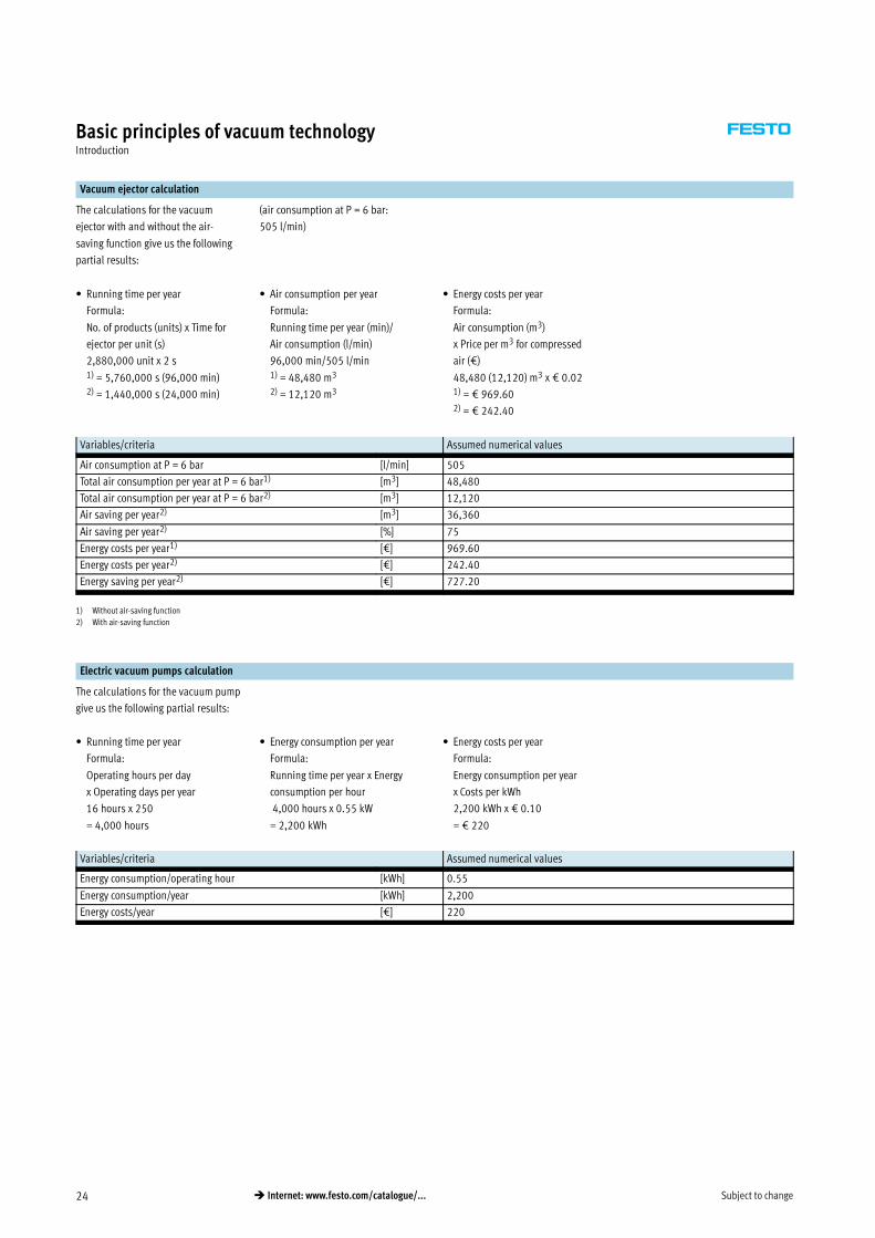
Vacuum ejector calculation
The calculations for the vacuum
ejector with and without the air-
saving function give us the following
partial results:
(air consumption at P = 6 bar:
505 l/min)
• Running time per year
Formula:
No. of products (units) x Time for
ejector per unit (s)
2,880,000 unit x 2 s1) = 5,760,000 s (96,000 min)2) = 1,440,000 s (24,000 min)
• Air consumption per year
Formula:
Running time per year (min)/
Air consumption (l/min)
96,000 min/505 l/min1) = 48,480 m3
2) = 12,120 m3
• Energy costs per year
Formula:
Air consumption (m3)
x Price per m3 for compressed
air (€)
48,480 (12,120) m3 x € 0.021) = € 969.602) = € 242.40
Variables/criteria Assumed numerical values
Air consumption at P = 6 bar [l/min] 505
Total air consumption per year at P = 6 bar1) [m3] 48,480
Total air consumption per year at P = 6 bar2) [m3] 12,120
Air saving per year2) [m3] 36,360
Air saving per year2) [%] 75
Energy costs per year1) [€] 969.60
Energy costs per year2) [€] 242.40
Energy saving per year2) [€] 727.20
1) Without air-saving function
2) With air-saving function
Electric vacuum pumps calculation
The calculations for the vacuum pump
give us the following partial results:
• Running time per year
Formula:
Operating hours per day
x Operating days per year
16 hours x 250
= 4,000 hours
• Energy consumption per year
Formula:
Running time per year x Energy
consumption per hour
4,000 hours x 0.55 kW
= 2,200 kWh
• Energy costs per year
Formula:
Energy consumption per year
x Costs per kWh
2,200 kWh x € 0.10
= € 220
Variables/criteria Assumed numerical values
Energy consumption/operating hour [kWh] 0.55
Energy consumption/year [kWh] 2,200
Energy costs/year [€] 220

Subject to change 25� Internet: www.festo.com/catalogue/...
Basic principles of vacuum technologyIntroduction
Cost comparison of the vacuum ejector and vacuum pump
The costs of the vacuum system are
made up of three cost types:
• Investment costs
• Maintenance costs
• Energy costs
Investment costs are one-off costs,
while maintenance and energy costs
are incurred annually.
Result
A direct cost comparison shows that
the vacuum pump has the lowest
energy costs, closely followed by the
ejector with the air-saving function.
The ejector without the air-saving
function has considerably higher
energy costs than the other vacuum
systems. If we also take maintenance
and investment costs into account,
this reduces the advantage that the
vacuum pump has over the other
systems due to its low energy costs.
Cost type Vacuum pump Ejector
without air-saving function
Ejector
with air-saving function
Investment [€] 715 337 337
Maintenance1) [€] 306 – –
Energy1) [€] 220 969.60 242.40
1) annual costs for a vacuum pump after approx. 4,000 to 6,000 hours
Conclusion
The calculation example shows that
ejectors more than justify their
existence.
The high investment costs for vacuum
pumps as well as the annual
maintenance costs associated with
their continuous use and wearing
parts confirm this conclusion.
While ejectors may use more energy,
their simple design keeps initial costs
and maintenance costs to a minimum.
There are, of course, a great many
areas of application that are
dominated by the vacuum pump and
where ejectors are not used. This is
not the case, however, with handling
technology.

Subject to change26 � Internet: www.festo.com/catalogue/...
Basic principles of vacuum technologyIntroduction
Leakage in vacuum systems
Ideally, when using vacuum
applications in handling technology,
the workpiece surfaces on which the
suction cups have to rest should be
smooth and impervious. A suction cup
fits tightly against this type of surface.
When a vacuum is generated, the
sealing rim of the suction cup can
fully seal the system against external
atmospheric air. We therefore
describe this as a leak-proof system.
The holding force of the suction
gripper on the workpiece increases as
the vacuum level in the system
increases compared with the external
atmospheric pressure.
Unfortunately, these ideal surface
conditions do not always exist on the
workpieces to be moved. The
materials are often air-permeable
(e.g. sheets of paper) or very rough
and uneven.
In these applications, the vacuum
suction grippers cannot completely
seal the system against atmospheric
air. If atmospheric air constantly
enters the system during vacuum
generation, we describe this as a
leaking system.
Leak-proof systems
In vacuum technology, the
performance of the vacuum generator
for the handling of leak-proof material
depends, among other things, on how
quickly the system can generate a
specific vacuum. This rating is known
as the evacuation time of the vacuum
generator.
When a specific volume is being
evacuated, the course of the time/
pressure curve travels upward
proportionally, i.e. the higher the
vacuum level, the stronger the fall in
the suction capacity of a vacuum
generator and the longer it takes to
attain an even higher vacuum level.
Evacuation time tE as a function of vacuum pu
pu [bar]
t E[s]
Leaking systems
The requirements for handling porous
materials (leaking systems) are
different. In order to attain or maintain
the desired vacuum level, the vacuum
generator must be capable of
continuously evacuating the air
(leakage air) entering the system.
The maximum attainable vacuum that
a vacuum generator can produce is
normally measured under ideal
conditions (leak-proof system).
However, in this case the leakage air
entering the system prevents the
vacuum generator from reaching or
being able to attain its maximum
performance level. To determine the
leakage air volume, it is recommended
that you carry out a test
(� 27, “Selecting vacuum generators
according to leakage flow”).
Remedy
In general, there are two options for
optimising or increasing the vacuum
level in leaking systems.
Target
Target
Actual
Actual
�
Option 1:
Using a high-performance vacuum
generator.
Advantage:
• Power transmitted as required
• Simple solution
Disadvantage:
• Leakage remains high
• High energy costs
Option 2:
Reducing the suction cup diameter or
orifices.
Advantage:
• Leakage is reduced (energy costs)
Disadvantage:
• Power transmission may be below
the required vacuum level.
To select the correct vacuum
generators for handling leakage flow,
you need to perform a test setup as
outlined above. With the aid of charts,
you can then select the right vacuum
generator.
This selection aid is described in
detail on page 27.

Subject to change 27� Internet: www.festo.com/catalogue/...
Basic principles of vacuum technologyIntroduction
Selecting vacuum generators according to leakage flow
A reliable method is needed to
determine the exact leak rate in
vacuum systems or applications. Only
then can optimal remedial action,
e.g. the selection of vacuum
generators with larger dimensions, be
taken and the functional reliability of
the vacuum system guaranteed.
Graphical representation as a tool
• Graphical representation
of the suction capacity in relation to
vacuum/operating pressure in a
chart (all ejectors in a single chart).
Suction capacity qn as a function of vacuum pu
1 VAD-y
2 VAD-¼
3 VAD-x
4 VAD-M5
pu [%]
qn[l/m
in]
All curves in the chart have an almost
linear downward course. The
maximum suction capacity of the
individual vacuum ejectors is reached
at atmospheric air pressure
(0% vacuum).
The higher the vacuum level, the lower
the suction capacity of a vacuum
generator, up to a maximum limit.
This chart is very useful for finding out
quickly and reliably whether a
vacuum generator is needed to
achieve the desired vacuum level with
leaking materials.
Test setup
• Perform a test setup
with an ejector as the vacuum
generator, a vacuum gauge
(pressure gauge) as the measuring
instrument as well as a suction
gripper and workpiece as the
leakage source. The test setup is
illustrated in the following figure.
1 Supply port
2 Suction cup connection
3 Exhaust port
The operating pressure (vacuum) of
the system is now measured at a
constant supply pressure. The
performance of an ejector under
normal operating conditions, i.e.
without leakage, can be determined
from its technical data as well as from
the ‘Suction capacity as a function of
vacuum/operating pressure’ chart.
The measurement results from the test
setup are then compared with the
known data.

Subject to change28 � Internet: www.festo.com/catalogue/...
Basic principles of vacuum technologyIntroduction
Selecting vacuum generators according to leakage flow
Procedure
Where systems are clearly leaking
(e.g. because of porous or rough
workpieces), the leak rate must be
determined.
The following procedure is
recommended for finding a suitable
vacuum generator that is compatible
with the relevant application and can
generate the required vacuum level:
Determining the leak rate
• Perform the test setup
• Read the vacuum or operating
pressure achieved
• Compare the result with the course
of the curve in the chart
• Suction capacity difference = leak
rate
In a test setup like the one illustrated
earlier, a workpiece is picked up using
a defined suction gripper size, a
vacuum generator and pressure
supply (5.5 … 6 bar).
In a leak-proof system, the value
indicated on the vacuum gauge must
correspond to the value contained in
the technical data for the vacuum
generator.
In a leaking system, the vacuum
attained is read from the vacuum
gauge.
The leak rate can then be determined
on the basis of the measured vacuum
value in conjunction with the chart
(Suction capacity as a function of
vacuum/operating pressure).
Example
In a test setup using the ejector2
VAD-¼, a vacuum level of 35% is
achieved at full pressure supply.
Starting from this result, if we draw a
horizontal line and a vertical line
intersecting the ejector curve2, the
residual airflow can be read from the
suction capacity scale.
This residual airflow corresponds to
the leak rate of the system, as in the
case of a leak-proof system the
residual airflow would be = 0.
Result:
The residual airflow or leak rate is
= 22 l/min.
The only disadvantage of this method
lies in the fact that it is impossible to
tell whether the leakage is caused by
the workpiece itself or by a rough
surface underneath the edge of the
suction gripper.
Determining the correct ejector size
• Compare the intersection of the
leak rate (now known) with the
curves of other ejectors.
• Determine the attainable vacuum
by projecting the intersections with
the leak rate downwards.
• Select the ejector that reaches the
required vacuum level.
Conversely, with a known leak rate of
22 l/min, we can now read the
vacuum level attainable with other
vacuum generators from the “Suction
capacity as a function of vacuum”
chart.
If we now extend the horizontal line
that we drew previously in the chart to
determine the leak rate (Procedure 1),
we can determine the vacuum level
attained with other vacuum
generators (at the same leak rate)
from the intersection with the curves
of other ejectors and the subsequent
downwards projection to the vacuum
scale.

Subject to change 29� Internet: www.festo.com/catalogue/...
Basic principles of vacuum technologyIntroduction
Selecting vacuum generators according to leakage flow
Example
If we extend this horizontal line, it
must intersect another curve. In the
case of the next largest vacuum
generator1 VAD-y, the line
intersects at 52% vacuum.
The curve for the next smallest
vacuum generator3 is overshot and
there is no intersection. In other
words, the low performance value
would mean that no vacuum is
generated with this leakage flow, as
the quantity of air drawn in is lower
than the quantity of air that is
discharged because of the leakage.
Suction capacity qn as a function of vacuum pu
1 VAD-y
2 VAD-¼
3 VAD-x
4 VAD-M5
pu [%]
qn[l/m
in]
Result:
In this application, the next largest
vacuum generator1 would attain a
vacuum level of 52%.
If this vacuum level were sufficiently
high for the application, this would be
the right choice of ejector. Otherwise,
a higher-performance ejector should
be chosen (curves not available in this
chart).
Conclusion
This method is useful for determining
the correct ejector size where the leak
rate is known.
However, it should be noted that
leakage can occur at other positions,
e.g.:
• seals,
• tubing connectors,
• couplings
in a vacuum system.
Leakage, for whatever reason, should
be avoided if at all possible.
• Safety risk
A leakage flow increases the risk of
the vacuum system no longer being
able to attain the required pressure
and the workpiece being dropped
during handling.
• Energy costs
Where there is a leakage flow, the
air consumption (energy
consumption) of an ejector is much
higher than that of a leak-proof
system.
• Time
A leakage flow means it takes
longer to reach the required
vacuum level.

Subject to change30 � Internet: www.festo.com/catalogue/...
Basic principles of vacuum technologyIntroduction
Technical symbols
Vacuum ejector Vacuum gauge Filter
This system description uses technical
symbols to represent individual
components in function charts as well
as in component descriptions.
These symbols are illustrated and
described in this section.
The technical symbol used in the
function charts for all Festo vacuum
generators.
Measuring and checking device for the
analogue vacuum display.
Filters the drawn-in air and prevents
contamination of the ejector.
Vacuum suction cups Non-return valve Reservoir container
Standard, extra-deep, round, oval.
In technical circuit diagrams, this
symbol represents the complete
suction gripper (suction cup
holder + suction cup + accessories).
Prevents the drawn-in air from flowing
back against the intake direction,
i.e. the valve permits flow in one
direction only.
Air reservoir to support the setting
down of a workpiece that was
previously picked up.
Bellows suction gripper Solenoid valve Throttle
1.5 convolutions, 3.5 convolutions. In
technical circuit diagrams, this
symbol represents the complete
suction gripper.
Different valve types (mostly 2-way
valves) perform the ON/OFF or exhaust
function in vacuum technology.
For controlling the flow rate or
pressure.
Silencers
Dampens the compressed air, which
flows from the venturi nozzle at
ultrasonic speed, before it is
discharged into the atmosphere.

Subject to change 31� Internet: www.festo.com/catalogue/...
Basic principles of vacuum technologyIntroduction
Circuit diagrams with vacuum components
Circuit diagrams help provide a
general understanding of the mode of
operation of vacuum components as
well as a schematic representation of
their function within the overall
system. The technical drawings below
contain examples of pneumatic circuit
diagrams. These are intended as a
reference to help you understand the
symbols used in vacuum technology.
Basic vacuum circuit
Regulated vacuum circuit

Subject to change32 � Internet: www.festo.com/catalogue/...
Basic principles of vacuum technologyIntroduction
Vacuum ejectors
Vacuum generators are the central
element of any vacuum system.
The mode of operation of vacuum
ejectors and the venturi principle
were already explained in the Basic
principles section (� 12).
Festo only uses ejectors that operate
according to the single-stage design
principle.
Festo offers a wide selection of
ejectors of different types and with
different equipment to suit a whole
host of application and performance
requirements.
These vacuum generators are
subdivided into the following ejector
groups:
• Basic ejectors
• Inline ejectors
• Compact ejectors
Each group is, in turn, subdivided into
a wide range of performance classes
and equipment types.
Standard and inline ejectors
The functions of standard and inline
ejectors are essentially limited to the
basic function of an ejector,
i.e. generation of a vacuum.
1 = Compressed air / nozzle
2 = Vacuum / suction port
3 = Exhaust air/receiver nozzle
Ejector/venturi nozzle
1
2
3
The ejector design basically consists
of just a single jet nozzle that
operates according to the venturi
principle.
VN-… VAD-…
Control, monitoring and other
functions depend on external and
additional components within the
vacuum system.
These ejectors are therefore much
smaller compared with other vacuum
ejectors.
1 Ejector
2 Suction cup holder
3 Suction cup
1
2
3
Because they are so compact, ejectors
of this type can generally be used
directly wherever a vacuum is
required, even in large quantities.
They are also used in vacuum
processes that do not require complex
and sophisticated control technology.

Subject to change 33� Internet: www.festo.com/catalogue/...
Basic principles of vacuum technologyIntroduction
Compact ejectors
In practice, demands on vacuum
systems in terms of function, speed
(performance) and, increasingly,
economy tend to be extensive.
Vacuum ejectors are therefore capable
of much more than just vacuum
generation. Compact ejectors have a
number of components integrated in
or on the housing, which makes them
complete function units.
Depending on the ejector and design,
these function units contain the
following components in addition to
the vacuum generator:
• Solenoid valves
• Filter
• Non-return valves
• Silencers
• Vacuum switch
Vacuum ejector VADMI-…
Taking a vacuum ejector VADMI--… as
an example, we can see the
components and functions of a
complete function unit.
The individual components are
identified in the sectional drawing
(�34). The functions, benefits and
special features are described in the
notes.

Subject to change34 � Internet: www.festo.com/catalogue/...
Basic principles of vacuum technologyIntroduction
General information
4
3
2
1
6
65
8
9aJ
aA
7
Components
1 Solenoid valve for ejector pulse
(VADMI-…, VAD-M…-I-…)
2 Venturi nozzle (jet and receiver
nozzle)
3 Special silencer
4 Vacuum switch
5 Filter for air to be evacuated
6 Two vacuum ports
7 Non-return valve
8 Supply port
9 Manual ejector pulse control
aJ Manual override
aA Solenoid valve for vacuum
generation
Description Function Benefits
1 Solenoid valve for ejector pulse
– 3/2-way valve
– Controls ejector pulse
If the voltage is switched off at the
solenoid valve for vacuum generation
aA and switched on at the solenoid
valve for ejector pulse, the vacuum is
rapidly purged at port6 as a result
of the application of pressure.
• Rapid purging of vacuum
• Fast and precise setting down of
workpieces
• Short vacuum ejector operation
cycles
2 Venturi nozzle (jet and receiver
nozzle)
– Most important ejector
component
– Used for vacuum generation
When pressure is supplied to the
supply port8, compressed air flows
into the jet nozzle. The narrowing of
the nozzle accelerates the compressed
air to up to 5 times the speed of
sound. This air flow is collected by the
receiver nozzle and directed into the
silencer3. A suction effect, which
evacuates the air from the filter5, is
created between the jet nozzle and the
receiver nozzle. A vacuum is created
at the vacuum port6.
• Ejector performance can be
modified and controlled by varying
the nozzle diameter or supply
pressure
3 Special silencer (closed, surface
or round type)
– For noise reduction in exhaust
air
The silencer is made from air-
permeable plastic or a metal alloy.
The air flow exits the jet nozzle at up
to 5 times the speed of sound. The
silencer dampens this air flow, thus
reducing the noise level before the
compressed air (exhaust air) enters
the atmosphere.
• Minimises the noise level from the
exhaust air during ejector operation

Subject to change 35� Internet: www.festo.com/catalogue/...
Basic principles of vacuum technologyIntroduction
Components
Description Function Benefits
4 Vacuum switch with PNP or NPN
output
– For pressure monitoring
On the vacuum switch, the vacuum
range for holding the workpiece is set
using two potentiometers. Once the
vacuum level is reached, a signal
switches off the vacuum generator
(air-saving function). The non-return
valve7 maintains the vacuum in this
status. If the vacuum range falls below
the required level, the signal controls
the switching on of the vacuum
generator. If the required vacuum can
no longer be generated because of a
malfunction, the vacuum generator is
switched off.
• Air-saving function: The vacuum
generator is switched off within the
required vacuum range
• Safety function: Control of vacuum
generator if vacuum level goes
above or below the required values
5 Filter for air to be evacuated
– With contamination indication
– 40 μm grade of filtration
A large plastic filter is integrated
between the vacuum port6 and the
vacuum generator2 or non-return
valve7. During the suction
operation, the air is filtered before it
enters the vacuum generator.
A removable display window shows
the degree of filter contamination.
• No contamination of the system
• Protection of components
• Display ensures maintenance is
carried out regularly
6 Two vacuum ports (V) or (2)
– With female thread
Vacuum components can be
connected here (e.g. vacuum suction
gripper).
Depending on the application, you
can use either one output or both
outputs simultaneously.
7 Built-in non-return valve After the vacuum generator is
switched off, this non-return valve
prevents a backflow of the drawn-in
air, thus preventing a drop in
pressure.
• The vacuum is maintained after the
vacuum generator is switched off
(air-saving function in connection
with the vacuum switch4 ).
8 Supply port (P) or (1) The compressed air supply port (P) or
(1) for generating the vacuum is con-
tained in the ejector housing.
9 Manual ejector pulse control The intensity of the air flow and,
consequently, the time taken to
remove the workpiece from the
suction gripper, can be adjusted
manually.
• The system can be optimised for the
vacuum application
aJ Manual override Stem on the solenoid valve that can
be switched without an electrical
signal. However, an electrical signal
that is already present cannot be
disabled.
• Manual switching of the solenoid
valve
aA Solenoid valve for vacuum
generation
– 3/2-way valve
– Controls vacuum generation
When the signal is activated,
compressed air flows through the
vacuum generator and creates a
vacuum. The air flow is interrupted
when the signal is turned off.
• Air-saving function in connection
with the vacuum switch4 and the
non-return valve7

Subject to change36 � Internet: www.festo.com/catalogue/...
Basic principles of vacuum technologyIntroduction
Important variables
Selecting a suction gripper
The main criteria to consider when
selecting a suction gripper:
• Total volume of the vacuum system • Cycle time of an operation • Ejector economy
• Additional functions
Total volume
The sum of the volumes is needed to
calculate the cycle time of an
operation.
The volume to be exhausted from the
system is made up of the following:
• Suction cup volume
• Suction cup holder volume
• Tube volume
Cycle time of an operation
When defining quantities, the time
factor plays a decisive role. The
evacuation time is used to determine
how economical an ejector is.
Individual criteria for determining the
duration of an operation cycle:
• Evacuation time: Time taken for the
ejector to generate the required
vacuum
• Air supply time: Time taken to set
down the workpiece under suction
(purging of the vacuum)
• Handling/return time
Evacuation time tE for 1 l volume at 6 bar operating pressure pu
1 VN-05-H-…
2 VN-07-H-…
5 VN-05-M-…
6 VN-07-M-…
pu [bar]
t E[s]
Ejector economy
Factors for determining the energy
consumption of an ejector:
• Air consumption per unit of time
(specified in the ejector technical
data)
• Number of operation cycles per unit
of time
Air consumption qn as a function of operating pressure p1
2 VN-07-H-…
VN-07-M-…
8 VN-07-L-…
p1 [bar]
qn[l/m
in]
Comparison of vacuum generators
Efficiency is a criterion which
facilitates an objective comparison of
various vacuum generator types.
The product section of this catalogue
contains information to help you
determine the efficiency of an ejector
(� 18).
The chart allows you to compare the
efficiency curves of other vacuum
generators.
Efficiency η as a function of vacuum Δpuat Pnom 6 bar
Δpu [bar]
η

Subject to change 37� Internet: www.festo.com/catalogue/...
Basic principles of vacuum technologyIntroduction
Suction grippers
General data
Vacuum suction grippers provide the
“link“ between the vacuum generator
and the workpiece being transported.
They are a simple, low-cost and
reliable solution for handling
workpieces, parts, packaging, etc.
Festo offers a wide range of suction
gripper designs:
• Universal suction gripper
• Flat suction gripper
• Bellows suction gripper
• Special suction gripper
Mode of operation
When the suction gripper comes into
contact with the workpiece surface,
the same air pressure (atmospheric
pressure) prevails on the top side and
underside of the suction cup. The
activated vacuum generator now
draws in the air on the underside of
the suction cup. A vacuum is created.
Given that air pressure within the
vacuum is lower than that on the
outside of the suction cup,
atmospheric pressure holds the
workpiece on the suction cup.
The larger the vacuum, the greater the
holding force pressing the suction cup
onto the workpiece.
Vacuum
Materials
The suction cups are available in
different materials.
• Nitrile rubber
• Polyurethane
• Polyurethane, heat-resistant
• Silicone
• Fluoro rubber
• Butadiene rubber, anti-static
Depending on the range of
application, the following conditions
play an important role when deciding
on the quality of the materials to be
used:
• Resistance to wear
• Intensity of stress
• Industry in which gripper is to be
used (food industry, electronics)
• Workpiece quality (surface, weight,
sensitivity, etc.)
• Environment (chemically aggressive
media, temperatures)
The criteria for selecting the right
suction cup material are summarised
in a table (� 44).
Shapes
Suction grippers can move a wide
variety of workpieces.
The range of workpiece surface
structures and contours available
demands versatile gripper technology.
Vacuum technology allows a wide
variety of products and materials
(shapeless, compact or porous) with a
wide variety of surfaces (even, uneven,
round, sloping or undulating) to be
handled easily, cost-effectively and,
above all, reliably.
Furthermore, it is possible to pick up
workpieces with masses ranging from
a few grammes right up to several
kilogrammes.
Accessories
For every suction cup there is a
suction cup holder to fit.
Depending on their design, these can
be used for a variety of applications.
The suction cup holders are
characterised based on the following
criteria:
• Holder size
• Suction cup connection
• With or without height compensator
• Position and type of vacuum port
• Mounting thread
Suction cup holders are more than
just mounting devices for suction
cups.

Subject to change38 � Internet: www.festo.com/catalogue/...
Basic principles of vacuum technologyIntroduction
Suction grippers
Advantages of a bellows suction cup
When the volume of a bellows suction
cup is evacuated, the suction cup
shape contracts slightly. The work-
piece is lifted gently in the process.
In practice, this so-called flexible
vertical stroke can be used as a short
vertical stroke to lift workpieces gently
from their supports.
The evacuation of a bellows suction
cup is divided into 2 phases:
Phase 1
The suction cup is positioned on top
of the workpiece without the influence
of any external forces.
Phase 2
A vacuum is created within the
suction cup. The workpiece is drawn
in and a state of equilibrium is
achieved depending upon the size of
the vacuum and the weight of the
workpiece.
WorkpieceWorkpiece
Suction gripper selection guidelines
When designing a suction gripper for
a specific handling task, there are
several criteria to be taken into
consideration:
Parameter Effects on
Required suction
force
No. of suction cups Suction cup shape Suction cup material
Workpiece dimensions� � –
Workpiece weight� � �
Workpiece rigidity– � �
Surface texture of the workpiece Harsh� � � �
Dry, wet� � –
Round, diagonal, curved– – �
Environmental influences such as
weather, cleaning agents, approval for
use in the food industry, temperature
– – – �
Distribution of suction grippers on the
workpiece� � –
Arrangement of suction gripper in
relation to direction of movement� � �
Max. acceleration� � �

Subject to change 39� Internet: www.festo.com/catalogue/...
Basic principles of vacuum technologyIntroduction
Physical variables
The physical variables described
below are components of the formulae
that are needed to calculate the main
criteria.
Coefficient of friction µ
The coefficient of friction is the friction
factor between the suction gripper
and workpiece. It defines the
tangential forces.
In practice, it is very difficult to obtain
precise specifications for this value.
Suitable experiments should therefore
be carried out for the relevant
application.
In order to be able to select a design,
the following theoretical guide values
apply:
Surfaces
Oily μ = 0.1
Wet μ = 0.2 … 0.3
Rough μ = 0.6
Wood, metal,
glass, stone … μ = 0.5
Safety value S
The regulations for the prevention of
accidents (UVV) stipulate a safety
factor of 1.5. This minimum value
must be incorporated in the
calculations.
In the case of critical, non-uniform or
porous materials or rough surfaces,
the factor should be increased to ≥ 2.
The safety value is also important for
the position of the suction gripper.
A higher factor should also be selected
in the case of a vertical suction
gripper position or swivel motions.
With a horizontal suction gripper
position, where the applied load acts
vertically on the suction cup, a value
of between 1.5 and 2 may be used.
Fv
Fh
FvFh
Theoretical holding force TH
This force is calculated with a dry
surface for the various load conditions
of the application.
The following factors are taken into
account in this formula:
• Mass of the workpiece m
• Coefficient of friction μ
• Acceleration of the system (m/s²)
• Acceleration due to gravity
(9.81 m/s²)
• Safety value S
Only the result from the most
unfavourable application load
condition is taken into consideration.
Breakaway force FA
The breakaway force depends on the
suction cup diameter and suction cup
shape.
If several suction grippers are used
simultaneously in a vacuum
application, the result of the
theoretical holding force TH
calculation must be divided by the
number of suction grippers.
This allows you to determine the
holding force of each suction gripper.
The breakaway force of the selected
suction cup must always be greater
than the determined holding force TH.
When selecting a suction gripper, you
can refer to the suction cup technical
data to find out its breakaway force.

Subject to change40 � Internet: www.festo.com/catalogue/...
Basic principles of vacuum technologyIntroduction
General procedure based on a calculation example
Purpose & benefits
For safety and financial reasons, it is
important that you design all
processes and methods in accordance
with their intended application. This is
the only way of ensuring optimal
deployment and utilisation of your
system. (This also applies to vacuum
technology.) It is therefore vital that
you create an optimal system design
for the application in advance, so that
the system can be sized and selected
in accordance with requirements.
To simplify this task, this section
provides a step-by-step description of
the basic procedure and theory
involved in selecting a vacuum
system.
A calculation example is provided to
illustrate how the theory is applied in
practice. You can follow the step-by-
step system design process with the
aid of this example.
The figure below illustrates step-by-
step the recommended in-house
procedure at Festo, which is used for
the design or selection of a vacuum
system.
Problem definition Suction cup selection Assembly/mounting attachments Vacuum generator
The problem definition produces
specifications as well as system
requirements.
• Material/surface
• Dimensions
• Directions of movement
• Cycle time/time allowed
• Design specifications
To design a suitable suction cup you
need to calculate the masses, holding
forces and breakaway forces
(� 43).
Workpiece surface finishes and
suction cup material requirements
must also be taken into account
(� 43).
The following criteria should be
considered when selecting mounting
attachments:
• Workpiece surface
• Position of the vacuum port
• Type of vacuum port
• Type of mounting
A table listing the available holders is
provided to help you select the right
holder.
When selecting a vacuum generator,
the following values must be
calculated:
• Total volume
• Cycle time
• Energy costs
Problem definition
– Description
– Data
Assembly/mounting attachments
– Retainer
– Height/angle compensator
Suction cups
– Workpiece (mass, surface)
– Load conditions (forces)
– General conditions
– Vacuum
Vacuum generator
– Volume
– Cycle time
– Energy costs
– General conditions

Subject to change 41� Internet: www.festo.com/catalogue/...
Basic principles of vacuum technologyIntroduction
Software tool
As a special service Festo offers you
free software. The software tool in
question is a reliable, convenient and,
above all, quick way of designing your
vacuum systems. It allows you to
specify the vacuum components of
your system individually and select
suggested products from the Festo
range. Vacuum selection software
www.festo.com/en/engineering
Software tool: Vacuum selection
Selection program for calculating the
mass of the workpiece
Program for selecting the suction
gripper

Subject to change42 � Internet: www.festo.com/catalogue/...
Basic principles of vacuum technologyIntroduction
Problem definition
Problem
definition
Assembly/
mounting components
Suction
cups
Vacuum
generator
A workpiece of mass X is to be
transported from point1 to point2
using a vacuum system.
Specifications for the workpiece and
general conditions for the vacuum
system are listed in the section below
(assumed values) and should be
referred to when performing the
necessary calculations.
Vacuum system, comprising:
• Suction cups
• Assembly/mounting attachments
• Vacuum generator
We need to find out which vacuum
system from the Festo product range
is the right one for this application. To
do this, we need certain values or
forces (required values).
1
2
Assumed values Required values
For the workpiece For the handling system
Material Sheet steel
Surface Even, smooth, slightly oily
(e.g. from the press)
Dimensions Length: 200 mm
Width: 100 mm
Height: 2 mm
Compressed air supply 6 bar
Directions of movement Lift vertically
Travel horizontally
90° Rotate
Travel vertically
Max. acceleration 5 m/s2
Cycle time max. 3.5 s
Time requirements For picking up: < 0.5 s
For setting down: 0.1 s
Safety factor 1.5
Design
conditions 2 suction grippers for
vibration-free transport;
spring-action picking up/
setting down of the workpiece;
vacuum line ports at side;
suction grippers mounted
using male threads.
The values specified below must be
calculated to determine the correct
vacuum system.
Other general conditions must be
taken into account here.
The following sequence is
recommended:
• Mass (weight) of the workpiece
• Holding force and force of
acceleration
• Total volume
• Cycle time
Other general conditions
• Material and surface finish
• Height and angle compensation
• Costs

Subject to change 43� Internet: www.festo.com/catalogue/...
Basic principles of vacuum technologyIntroduction
Selection of suction cups
Problem
definition
Assembly/
mounting components
Suction
cups
Vacuum
generator
Check list
Load Workpiece surface Suction cup material Forces
What does the workpiece weigh? What kind of surface finish does the
workpiece have?
What requirements must the vacuum
generator fulfil?
• Areas of application
• Resistance requirements,
temperature
What kind of loads do the suction
grippers have to carry?
• Holding forces – load cases in the
various directions of movement
• Breakaway force – determining the
breakaway force per suction cup
(definition of suction cup diameter)
Step 1: Calculating the mass m of the workpiece
m = L x W x H x ρ Example:
m = 20 cm x 10 cm x 0.2 cm
x 7.85 g/cm3
m = 314 g
m = 0.314 kg
m = Mass [kg]
L = Length [cm]
W = Width [cm]
H = Height [cm]
ρ = Density [g/cm³]
Step 2: Selection of the suction gripper
According to the surface finish of the workpiece
Different suction cup shapes are
recommended for the suction gripper,
depending on the surface finish of the
workpiece:
Standard suction cup
• For flat and slightly undulating
surfaces, e.g. sheet metal or
cartons.
Extra deep suction cup
• For round or deeply undulating
workpieces
Oval suction cup
For narrow, oblong workpieces such
as profiles and pipes
Bellows
• For inclined surfaces, from 5 to 30°
depending upon suction cup
diameter
• Undulating, round surfaces, flexible
workpieces with large surface areas
• Fragile workpieces such as glass
bottles
• Use as a cost-effective height
compensator
Result
If, in the sample exercise, we were
using sheet steel with an even,
smooth surface, a standard suction
cup would be the best solution.

Subject to change44 � Internet: www.festo.com/catalogue/...
Basic principles of vacuum technologyIntroduction
Step 2: Selection of the suction gripper
According to the material quality of the workpiece
Depending on the application, the
following conditions need to be taken
into consideration:
• Continuous load in multiple shift
operation
• Life expectancy
• Environment (e.g. chemically
aggressive media, temperatures)
There are different material designs
available, such as:
• For smooth or rough surfaces
• For high temperatures
• Antistatic design for electronics
components
Material properties Nitrile rubber Polyurethane Polyurethane
(heat-resistant)
Silicone Fluoro rubber Butadiene rubber
(anti-static)
Material code N U T S F NA
Colour Black Blue Red-brown White
transparent
Grey Black with white
dot
�Resistance to wear/
resistance to abrasion
** *** *** * ** **
Areas of application
Very high stress – * * * – –
Food processing – – – * – –
� Oily workpieces * * *** – * *
High ambient temperatures – – – * * –
Low ambient temperatures – * * * – –
� Smooth surface (glass) * * * – * –
Rough surface (wood, stone) – * ** – – –
Antistatic – – – – – *
Minimal marking – * * * – –
Resistance
Weather * ** ** *** *** **
� Resistance to tearing ** *** *** * ** **
Permanent deformation ** * ** ** *** **
Mineral based hydraulic oil *** *** *** – *** –
Synthetic ester based hydraulic oil * – – – * –
Non-polar solvents (e.g. white spirit) *** ** ** – *** –
Polar solvents (e.g. acetone) – – – – – –
Ethanol *** – – *** * –
Isopropanol ** – – *** *** –
Water *** – – ** ** –
Acid (10%) – – – * *** –
Alkaline (10%) ** * * *** ** –
Temperature range, long-term [°C] –10 … +70 –20 … +60 –10 … +80 –30 … +180 –10 … +200 –10 … +70
Shore hardness A [°] 50 ±5 60 ±5 72 ±5 50 ±5 60 ±5 50 ±5
Special features Low-cost Wear resistant Oil resistant Approved for
use in the food
industry
Chemical and
temperature
resistant
Antistatic
Area of application Conventional
application
Rough surface Automobile
industry
Food industry Glass industry Electronics
industry
*** Very suitable
** Fairly suitable
* Suitable
– Not suitable
Result
For the workpiece in the problem example we would choose a suction cup made from polyurethane (material code U).

Subject to change 45� Internet: www.festo.com/catalogue/...
Basic principles of vacuum technologyIntroduction
Step 3: Calculating the holding force and breakaway force
Determining the holding force
To determine the holding force you
need to know the mass of the
workpiece, on the one hand, and the
acceleration, on the other.
-H- Note
The forces of acceleration that operate
in a fully automatic system must be
taken into consideration when
designing a suction gripper system.
Case 1
Horizontal suction gripper position,
vertical direction of movement (best
case)
FH = m x (g+ a) x SExample:
FH≈ 7 N
FH = 0.314 kg x (9.81 ms2
+ 5 ms2) x 1.5
Case 2
Horizontal suction gripper position,
horizontal direction of movementFH = m x (g+ a
�) x S
Example:
FH≈ 28 N
FH = 0.314 kg x (9.81 ms2
+5 m
s2
0.1) x 1.5
Case 3
Vertical suction gripper position,
vertical direction of movement (worst
case)
FH = (m�) x (g+ a) x S
Example:
FH≈ 93 N
FH = (0.314 kg
0.1) x (9.81 m
s2+ 5 m
s2) x 2
Result:
In accordance with the problem
definition, the result of 93 N from
Case 3 must be taken into account, as
the system also transports the
workpiece in a vertical suction gripper
position with vertical force.
This value must be used for designing
the system.
FH = Theoretical holding force of the
suction gripper [N]
m = Mass [kg]
g = Acceleration due to gravity
[9.81 m/s2]
a = Acceleration of the system
[m/s²]
Note the emergency off acceler-
ation.
S = Safety factor
(minimum value is a safety
factor of 1.5, for critical, non-
uniform or porous materials or
rough surfaces the factor
should be 2.0 or higher)
μ = Friction factor1)
0.1 for oily surfaces
0.2 …0.3 for wet surfaces
0.5 for wood, metal, glass,
stone …
0.6 for rough surfaces
1) The specified friction factors are average values and should be verified for the workpiece in question.

Subject to change46 � Internet: www.festo.com/catalogue/...
Basic principles of vacuum technologyIntroduction
Step 3: Calculating the holding force and breakaway force
Determining the breakaway force
FA = Theoretical breakaway force
[N]
FH = Theoretical holding force of the
suction gripper [N]
(Result� 45)
n = Number of suction grippers
(2 suction grippers are
planned in the problem
example)
FA =FHn
Example:
FA≈ 47 N
FA =93 N2
Breakaway force FA dependent on suction cup diameter and suction cup shape
Round suction cup FA
at –0.7 bar
Oval suction cup FA at
–0.7 bar
Ordering
data
Suction
cup∅
Standard Extra deep Bellows,
1.5 convol-
utions
Bellows,
3.5 convol-
utions
Ordering
data
Suction
cup size
Oval
[mm] [mm]
Breakaway force FA too low
�
� ess 2 0.1 N � ess 4x10 2 N
4 0.4 N 4x20 3.4 N
6 1.1 N 6x10 2.9 N
8 2.3 N 6x20 5.9 N
10 3.9 N 4.7 N 3.9 N 8x20 8 N
15 8.5 N 9.8 N 8x30 10.9 N
20 16.3 N 17 N 12.9 N 8.2 N 10x30 15.2 N
30 40.8 N 37.2 N 26.2 N 20.8 N 15x45 32 N
Reliable range
for the problem example
40 69.6 N 67.6 N 52.3 N 42.4 N 20x60 62.8 N
50 105.8 N 103.6 N 72.6 N 63.4 N 25x75 92.5 N
60 166.1 N 162.5 N 30x90 134.4 N
80 309.7 N 275 N 213.9 N
100 503.6 N 440.8 N
�
Suction cup diameter too big for
workpiece
150 900 N
200 1,610 N
In this example we opt for 2 suction
grippers:
• Round design
• Suction cup diameter 40 mm
• Breakaway force of 69.6 N
-H- Note
The load capacity of the vacuum
suction gripper must be greater
than the calculated value.

Subject to change 47� Internet: www.festo.com/catalogue/...
Basic principles of vacuum technologyIntroduction
Selecting assembly/mounting attachments
Problem
definition
Assembly/
mounting components
Suction
cups
Vacuum
generator
Check list
Workpiece Vacuum port Type of connection Type of mounting
Consideration of the workpiece
surface
• Angle compensator for very uneven
surfaces
• Spring-mounted holders for
sensitive workpieces as well as
varying pick-up heights
Positioning of the vacuum tubing
• top
• at side
Selecting the vacuum port for the
suction cup holder
• Thread, push-in connector, barbed
fitting
Mounting the suction cup holder on
the handling unit, e.g. robot arm
• Female/male thread
Selecting the suction cup holder
The suction cup holder as well as the
“angle compensator” and “vacuum
filter” accessories are selected on the
basis of the previously defined
suction cup diameter.
According to the problem example, the
workpieces must be picked up and set
down with the aid of a spring.
The vacuum lines should be attached
at the side using push-in connectors.
The suction grippers should be
mounted with external threads.
• Spring-loaded holders:
In the event of excess stroke and
height tolerances, it is recom-
mended that you use a holder with
a height compensator – the same
applies for sensitive workpieces that
need to be placed gently and with
the aid of a spring.
• Choice of vacuum ports1:
– top
– at side
• 3 connection types1:
– Push-in connector QS
– Barbed fitting PK
– Thread G
• Different mounting threads for
holder2:
– Female thread
– Male thread
Vacuum port1
Mounting
threads for
holder2Suction cup
connection3
Round suction cup
From problem example
�
Suction cup∅ 2 4 6 8 10 15 20 30 40 50 60 80 100 150 200
[mm]
Holder size 1 2 3 4 5 6
Suction cup connection
3
3 mm 4 mm M4x0.7 M6x1 M10x1.5 M20x2
Ordering data � esh
Oval suction cup
Suction cup size 4x10 4x20 6x10 6x20 8x20 8x30 10x30 15x45 20x60 25x75 30x90
[mm]
Holder size 4 5
Suction cup connection
3
M6x1 M10x1.5
Ordering data � esh

Subject to change48 � Internet: www.festo.com/catalogue/...
Basic principles of vacuum technologyIntroduction
Holder type
From problem example
�
�
HA HB HC HCL HD HDL HE HF
Height compensation – – –
Vacuum port1
�
�
Top – – –
At side – – – – –
Threaded connection G
Push-in connector QS – –
Barbed fitting PK – –
Mounting threads for holder2
�
Female thread – – – – – – –
Male thread –
Result
Taking all requirements into account:
Suction cup holder HD, size 4

Subject to change 49� Internet: www.festo.com/catalogue/...
Basic principles of vacuum technologyIntroduction
Selecting vacuum generators
Problem
definition
Assembly/
mounting components
Suction
cup
selection
Vacuum
generator
The criteria referred to in the check
list therefore play an important role in
the selection of a suitable ejector.
• Total volume
• Cycle time
• Economy
• Functions
• Design specifications
-H- Note
Almost all Festo vacuum ejectors
achieve a vacuum level of approx.
85%, with the exception of the new
VN ejectors, which are specially
designed for low pressure of approx.
50%.
All ejectors can thus be used for
handling tasks involving light to
heavy workpieces or loads.
Check list
Total volume Cycle time Economy Functions
How high is the total volume to be
drawn in?
• Take into account the suction cup
volume
• Take into account the suction cup
holder volume
• Calculate the tube volume
How long does an operation cycle
take?
• Calculate the evacuation time
• Determine the handling/return time
• Calculate the air supply time
How high are the energy costs?
• Calculate the energy costs based on
the air consumption and number of
operation cycles
What additional functions should the
vacuum generator have?
• Filters, controls, non-return valves,
vacuum switches, exhaust function,
etc.
Design specifications
What specifications exist?
• Dimensions, weight, mounting
position, etc.

Subject to change50 � Internet: www.festo.com/catalogue/...
Basic principles of vacuum technologyIntroduction
Step 1: Determining the total volume of the system (volume to be drawn in)
The suction cup, holder and tube
volumes must be determined and
added together to form the total
volume.
Suction cup volume V1 Suction cup holder volume V2 Tube volume V3 Total volume VT
The suction cup volumes are specified
in the datasheet for the relevant
vacuum suction grippers ESG, VAS,
VASB.
The suction cup volume may be
specified in a table or chart,
depending on the product family.
In our sample application we opted
for 2 suction grippers:
• Round design
• Suction cup diameter 40 mm
• Breakaway force of 69.6 N
For these suction cups, the datasheet
specifies a suction cup volume
of 1,566 mm3 per suction cup.
V1= 2 x 1,566 mm3 = 3,132 mm3
Because of the huge range of different
holder types and connection options,
tables listing all of the suction cups
and their relevant volumes have been
created in the datasheet for the ESG
product family.
In our sample application we chose
the following suction cup holders:
• Suction cup holder HD
Size 4 with QS connector
V2 = 678 mm3
Once the suction cups, suction cup
holders and connection options have
been defined, the tube volume can be
determined.
Tubing PUN:
Outside/inside∅ [mm]
3.0/2.1
4.0/2.6
6.0/4.0
8.0/5.7
10.0/7.0
The following formula must be used
when calculating the volume:
D = Tube inside∅ [mm]
L = Tube length [mm]
In the sample application a suction
cup holder with QS-6 couplings is
used. A tube with an outside diameter
of 6 mm is therefore required.
In order to connect the vacuum
generator to both suction cups, a tube
length (L) of approx. 1 m (1,000 mm)
is required.
V3 = π x D2
4x L
V3 = π x42
4x 1 000
V3 = 12 566 mm3
VT = V1 + V2 + V3VT = 3,132 + 678 + 12,566
VT = 16,376 mm3 (16.38 cm3)

Subject to change 51� Internet: www.festo.com/catalogue/...
Basic principles of vacuum technologyIntroduction
Step 2: Determining the cycle time
TC = Evacuation time tE + handling
time t1 + air supply time tS + return
time t2
p[bar]
(tE)1
(t1)
(tS)
(t2)
2
tE = Evacuation time
t1 = Transport
tS = Discharge
t2 = Return
1 = Pick-up
2 = Time saved
t [s]
An operation cycle can be subdivided
into individual time intervals, which
must be either measured or
calculated. The individual times
added together produce the cycle
time.
Evacuation time tE
The evacuation time, i.e. the time
taken for a volume to reach a certain
vacuum level, is very useful for
assessing the performance of a
vacuum generator. The evacuation
time can be found in the
datasheet of the relevant vacuum
generator. This example depicts charts
for some of the vacuum generators of
the VN-… product family.
Calculation:
In Step 1 of the sample application we
determined a total volume for the
vacuum system of VT = 16.38 cm3
(17 cm3). Using a basic rule of three,
we can now calculate the evacuation
time tE for this system with any
vacuum generator. According to the
problem definition, tE < 0.5 s, based
on a vacuum level of 80%.
Example 1: VADMI-45
tE = VT x tE1/1,000
tE = 17 cm3 x 25 s/1,000 cm3
tE = 0.425 s (0.43 s)
Example 2: VADMI-70
tE = VT x tE1/1,000
tE = 17 cm3 x 11 s/1,000 cm3
tE = 0.187 s (0.19 s)
Example 3: VN-07-H
tE = VT x tE1/1,000
tE = 17 cm3 x 8 s/1,000 cm3
tE = 0.136 s (0.14 s)
tE = Evacuation time (VT )
tE1 = Evacuation time (V = 1,000 cm3)
VT = Total volume (from example)
Evacuation time tE for 1 litre volume at 6 bar operating pressure pu
pu [bar]
t E[s]
1 VN-05-H-…
2 VN-07-H-…
5 VN-05-M-…
6 VN-07-M-…
Handling time t1
The time required to handle the
workpiece after the end of the suction
process (e.g. determined using a
stopwatch = 1.5 s).
Air supply time tS
Time needed by the vacuum system to
build up the pressure (vacuum) again
and set down the workpiece. The air
supply time can be found in the
technical data for the relevant vacuum
generator.
The specifications apply to 1 litre
volume at 6 bar operating pressure at
max. vacuum level.
Using a basic rule of three, we can
now calculate the air supply time tS
for this system.
tS = Evacuation time (VT)
tS1 = Evacuation time (V = 1,000 cm3)
VT = Total volume (from example)
Example 1: VADMI-45
tS = VT x tS1/1,000
tS= 17 cm3 x 1.9 s/1,000 cm3
tS = 0.03 s
Example 2: VADMI-70
tS = VT x tS1/1,000
tS= 17 cm3 x 0.59 s/1,000 cm3
tS= 0.01 s
Example 3: VN-07-H
tS = VT x tS1/1,000
tS= 17 cm3 x 1.1 s/1,000 cm3
tS= 0.02 s
Return time t2 Cycle time tC
The time needed by the vacuum
system to return to the initial position
after the workpiece has been set down
(e.g. determined using a stopwatch
= 1.5 s).
Example 1: VADMI-45
tC = tE + t1 + tS + t2tC = 0.43 + 1.5 + 0.03 + 1.5
tC = 3.46 s
Example 2: VADMI-70
tC = tE + t1 + tS + t2tC = 0.19 + 1.5 + 0.01 + 1.5
tC = 3.2 s
Example 3: VN-07-H
tC = tE + t1 + tS + t2tC = 0.14 + 1.5 +0.02 + 1.5
tC = 3.16 s

Subject to change52 � Internet: www.festo.com/catalogue/...
Basic principles of vacuum technologyIntroduction
Step 3: Checking economy of operation
Energy costs are determined on the
basis of air consumption.
Determining the air consumption per operation cycle QC
These charts are also included in the
datasheet for the relevant vacuum
generator (e.g. VADM-…, VADMI-…).
The VADMI-… vacuum generators have
a built-in non-return valve which
maintains the vacuum after the
vacuum generator has been switched
off (prerequisite: there must be no
leakage in the system).
When combined with the vacuum
switch it provides an air-saving
function, i.e. no air is consumed
during transport of the workpiece.
The VN-… vacuum generators do not
have this function. This means,
therefore, that the vacuum generator
remains in operation so that it can
hold the workpiece during transport.
Air consumption Q as a function of operating pressure p
p [bar]
Q[l/m
in]
Qz = Air consumption per operation cycle
tE = Evacuation time for application
Q = Air consumption per vacuum generator
[l/min]
Example 1: VADMI-45
QZ = tE xQ60
QZ = 0.43 s x 11 l60 s
QZ = 0.08 l
Example 2: VADMI-70
QZ = tE xQ60
QZ = 0.19 s x 31 l60 s
QZ = 0.10 l
Example 3: VN-07-H
QZ = �tE + t1� xQ60
QZ = (0.13 s + 1.5 s) x 28 l60 s
QZ = 0.76 l
Determining the number of operation cycles per hour Zh
Zh = Operation cycles per hour
tZ = Time per operation cycle
tE = Evacuation time for application
Example 1: VADMI-45
Zh =3, 600 s
tZ
Zh =3, 600 s3.46 s
Zh = 1, 040
Example 2: VADMI-70
Zh =
3, 600 stZ
Zh =3, 600 s3.2 s
Zh = 1, 125
Example 3: VN-07-H
Zh =
3, 600 stZ
Zh =3, 600 s3.16 s
Zh = 1, 139
Determining the air consumption per hour Qh
Qh = Air consumption per hour
QC = Air consumption per operation cycle
Ch = Operation cycles per hour
Example 1: VADMI-45
Qh = QC x ChQh = 0.08 l x 1,040
Qh = 83.20 l (0.08 m³)
Example 2: VADMI-70
Qh = QC x ChQh = 0.10 l x 1,125
Qh = 112.5 l (0.12 m³)
Example 3: VN-07-H
Qh = QC x ChQh = 0.76 l x 1,139
Qh = 865.64 l (0.87 m³)
Determining the energy costs per year KEA
KEA = Energy costs per year
Qh = Air consumption per hourCosts for compressed air1):
1 m³ at 7 bar: € 0.02/m³,
at an electricity price of
€ 0.10/kWh
KEA = Qh x Compressed air costs�m3 xtoperatingDay
xtoperatingYear
Vacuum generator Air consumption per cycle QZ
[l]
Cycles per hour Zh Air consumption per hour Qh
[m3]
Energy costs per year KEA2)
[€]
VADMI-45 0.08 1,040 0.08 5.76
VADMI-70 0.10 1,125 0.12 8.64
VN-07-H 0.76 1,139 0.87 62.63
1) Material, depreciation and labour costs, etc. are reflected in the price
2) Energy costs for shift operation 16 hours/day and 220 days/year

Subject to change 53� Internet: www.festo.com/catalogue/...
Basic principles of vacuum technologyIntroduction
Step 4: Taking additional functions/components and design specifications into account
Selecting additional functions/components:
Selection of these components is
guided by specific requirements in
terms of performance and functional-
ity, as well as by the place of operation
and application of the system. All
details regarding performance or
components are provided in the
datasheet on the relevant product.
Solenoid valves Vacuum switch
A vacuum system needs solenoid
valves for controlling vacuum
generation. These switch the vacuum
on and off.
Vacuum generator
• VADM-…, VADMI-…
• VAD-M-…, VAD-M…-I-…
Operation cycles can be accelerated
and optimised by adding an extra
valve as an ejector pulse generator.
Vacuum generator
• VADMI…-
• VADM…-I-…
-H- Note
The nominal flow rate of the
solenoid valve must not be lower
than the suction capacity of the
vacuum generator at atmospheric
pressure. (Both specifications can
be found in the datasheet for the
relevant product.)
• Reliability through pressure
monitoring
• Adjustable switching point
• Fast hysteresis adjustment
• Digital/analogue signal output
• Display
• Ports
Filter Pressure gauge Silencers
• Reliability: no contamination of the
system
• Extension of the product life cycle
and reduction of maintenance
intervals
• Manual pressure monitoring of the
system
• Safety function
• Noise pollution kept to a minimum
Taking design specifications into account
The following design specifications
must be taken into account when
configuring a vacuum system:
• Size
• Weight
• Resistance
Calculation example summary Selection of suction cups Selecting assembly and mounting
attachments
Selecting vacuum generators
The cycle time and economy of the
ejectors were used as selection
criteria.
Taking the mass and force
calculations plus all criteria into
account, we get the following result:
Quantity 2 units
Design round
Suction cup∅ 40 mm
Breakaway force 69.4 N
Material Polyurethane
The result takes all system
requirements into account:
Holder type HD
Size 4
We compared three vacuum
generators chosen at random from the
Festo product range:
Compact ejectors VADMI-45
VADMI-70
Inline ejectors VN-07-H
Result Cycle time Economy
Compact ejector VADMI-45 All three vacuum generators lay within
a reasonable timeframe in the sample
application and were below the
maximum time of 3.5 seconds
specified in the problem definition.
The vacuum generator VADMI-45 came
off best in terms of energy consump-
tion and, consequently, energy costs.
The two compact ejectors VADMI-45
and VADMI-70 produced almost
identical results in relation to energy
costs. Although the larger VADMI-70
has a somewhat higher air consump-
tion per unit of time, it can generate
the vacuum faster.
The VADMI-45, on the other hand, has
a smaller nozzle diameter and thus
significantly lower air consumption.
However, it cannot generate the
vacuum as quickly as the VADMI-70.
The number of cycles per unit of time
and the quantities are almost
identical for all three vacuum
generators.

Subject to change54 � Internet: www.festo.com/catalogue/...
Basic principles of vacuum technologyIntroduction
Products for vacuum technology
Vacuum generator Vacuum suction gripper
A vacuum ejector is the central
element of any vacuum system.
Festo offers an extensive range of
vacuum ejectors for all kinds of
applications and performance
requirements:
Basic and inline ejectors
Vacuum generators
VN-…, VAD-…/VAK-…
Compact ejectors
Vacuum generators
VADM-…/VADMI-…,
VAD-M…/VAD-M…-I-…
The suction grippers are the connect-
ing element between the vacuum
system and the workpiece.
Given the huge variety of surface
finishes, shapes and temperatures as
well as different workpiece masses, a
comprehensive range of suction cups
and possible combinations is needed.
With its suction cup range and the
modular suction gripper ESG, Festo
has a solution for every application:
Modular suction gripper ESG-…
Suction cups VAS-…/VASB-…
Vacuum accessories
Controlling, measuring, checking,
filtering, etc. are important functions
which, if not already included as
standard in a vacuum system, can be
added through an extensive range of
accessories.
Vacuum security valve ISV-…
Vacuum gauges VAM-…
Vacuum filters VAF-…
Vacuum switches VPEV-…
Other accessories:
Height compensators, adapters
Tubing
QS push-in fittings