Embed Size (px)
Citation preview
Basic PXL Configuration in Doors.NETTM
Application Note
Doors.NET installation and controller configuration is a three step process. Each of these steps has its own document, with controller configuration broken into separate documents per hardware type.
• software installation – DoorsNET_Software_Installation.pdf (p/n 01565-001)• license manager and gateway configuration – License_Manager_and_Gateway_Configuration.pdf (p/n: 01565-002)• controller configuration – this document
This document covers the basic configuration of PXL controllers in Doors.NET software. It assumes Doors.NET has already been successfully installed on your host PC, the software license has been activated, and the gateway has been configured for your controller type.
1.0 Replicating Sites Mode in Doors.NETDoors.NET can replicate Doors32’s Sites mode by using multiple master controllers. This allows you to maintain the Sites mode style organization. A standard Doors.NET PXL license can support up to 128 controllers and 256 doors. However with an extended license, Doors.NET can support up to 64 master controllers, replicating up to 64 Sites, and each master controller can have up to 127 slave controllers and 256 doors. Doors.NET allows all sites to be monitored, administered, and updated concurrently; something that is not possible in Doors32.
2.0 Adding a PXL-500 Master Controller to the PXL Gateway
To use a PXL controller network you must first establish a connection to the master controller. Communication to the master controller can be made via a serial, Ethernet, or modem connection. Each master controller will have a communications channel enabled, setup, and assigned to it. All slave controllers are then added to the system using auto-configuration.
1. Open the Doors.NET login window by clicking on the client icon on the desktop.
2. Login to the software using the default username and password of admin / admin, then click Connect.3. Click the Setup tab then click Hardware Setup.
4. Click the All tab and the PXL gateway appears at the top of the hardware tree.
Page 1 of 16 P/N: 01238-001 Rev. C
Basic PXL Configuration in Doors.NETTM
Application Note
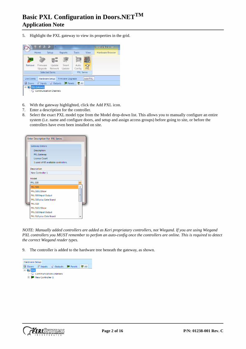
5. Highlight the PXL gateway to view its properties in the grid.
6. With the gateway highlighted, click the Add PXL icon.7. Enter a description for the controller.8. Select the exact PXL model type from the Model drop-down list. This allows you to manually configure an entire
system (i.e. name and configure doors, and setup and assign access groups) before going to site, or before the controllers have even been installed on site.
NOTE: Manually added controllers are added as Keri propriatary controllers, not Wiegand. If you are using Wiegand PXL controllers you MUST remember to perfom an auto-config once the controllers are online. This is required to detect the correct Wiegand reader types.
9. The controller is added to the hardware tree beneath the gateway, as shown.
Page 2 of 16 P/N: 01238-001 Rev. C
Basic PXL Configuration in Doors.NETTM
Application Note
3.0 Configure the Communication ChannelIf you are upgrading from Doors32 and your existing installation uses sites mode, Doors.NET accepts multiple master controllers allowing you to continue to maintain the sites mode style organization. Each site’s master controller will require its own communication channel.
There are three different communication channels available, one of which must be assigned to the master PXL controller for establishing communication to the PXL network. All slave controllers are added to the software using Auto-configuration.
You can communicate to a PXL using Doors.NET via:
• a serial connection (from the PC’s physical COM port, a recommended USB to Serial adapter, or a Keri USB Comm Module)
• a modem connection• over Ethernet using a LAN module such as the LAN-520
Follow the set of instructions for each site according to your communication method.
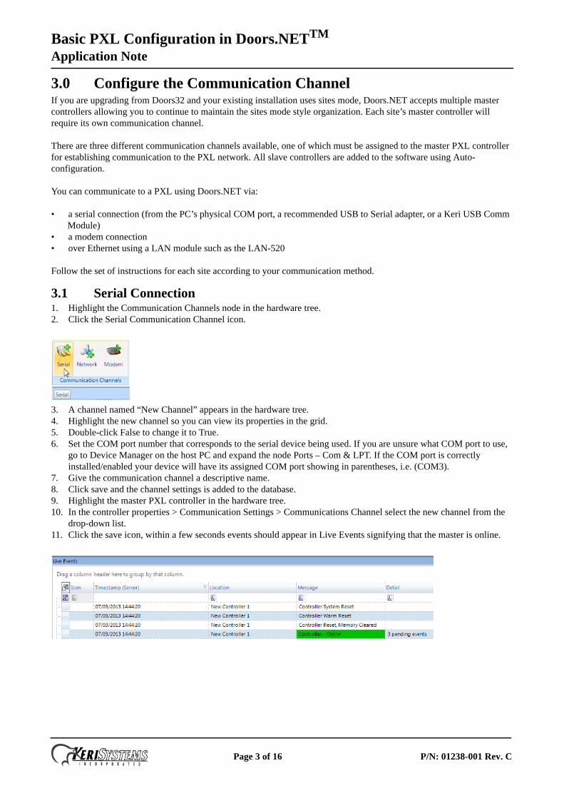
3.1 Serial Connection1. Highlight the Communication Channels node in the hardware tree.2. Click the Serial Communication Channel icon.
3. A channel named “New Channel” appears in the hardware tree.4. Highlight the new channel so you can view its properties in the grid.5. Double-click False to change it to True.6. Set the COM port number that corresponds to the serial device being used. If you are unsure what COM port to use,
go to Device Manager on the host PC and expand the node Ports – Com & LPT. If the COM port is correctly installed/enabled your device will have its assigned COM port showing in parentheses, i.e. (COM3).
7. Give the communication channel a descriptive name.8. Click save and the channel settings is added to the database.9. Highlight the master PXL controller in the hardware tree.10. In the controller properties > Communication Settings > Communications Channel select the new channel from the
drop-down list.11. Click the save icon, within a few seconds events should appear in Live Events signifying that the master is online.
Page 3 of 16 P/N: 01238-001 Rev. C
Basic PXL Configuration in Doors.NETTM
Application Note
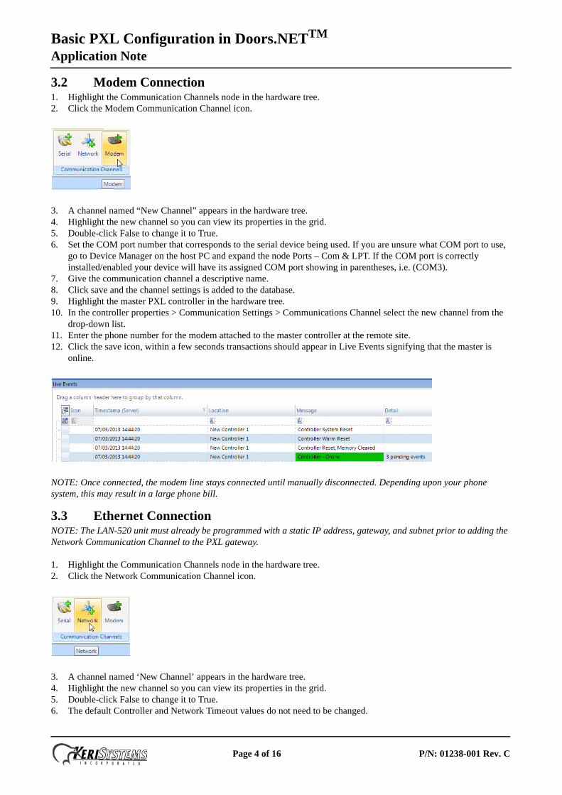
3.2 Modem Connection1. Highlight the Communication Channels node in the hardware tree.2. Click the Modem Communication Channel icon.
3. A channel named “New Channel” appears in the hardware tree.4. Highlight the new channel so you can view its properties in the grid.5. Double-click False to change it to True.6. Set the COM port number that corresponds to the serial device being used. If you are unsure what COM port to use,
go to Device Manager on the host PC and expand the node Ports – Com & LPT. If the COM port is correctly installed/enabled your device will have its assigned COM port showing in parentheses, i.e. (COM3).
7. Give the communication channel a descriptive name.8. Click save and the channel settings is added to the database.9. Highlight the master PXL controller in the hardware tree.10. In the controller properties > Communication Settings > Communications Channel select the new channel from the
drop-down list.11. Enter the phone number for the modem attached to the master controller at the remote site.12. Click the save icon, within a few seconds transactions should appear in Live Events signifying that the master is
online.
NOTE: Once connected, the modem line stays connected until manually disconnected. Depending upon your phone system, this may result in a large phone bill.
3.3 Ethernet ConnectionNOTE: The LAN-520 unit must already be programmed with a static IP address, gateway, and subnet prior to adding the Network Communication Channel to the PXL gateway.
1. Highlight the Communication Channels node in the hardware tree.2. Click the Network Communication Channel icon.
3. A channel named ‘New Channel’ appears in the hardware tree.4. Highlight the new channel so you can view its properties in the grid.5. Double-click False to change it to True.6. The default Controller and Network Timeout values do not need to be changed.
Page 4 of 16 P/N: 01238-001 Rev. C
Basic PXL Configuration in Doors.NETTM
Application Note
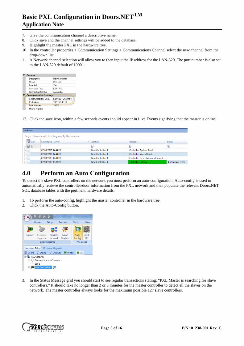
7. Give the communication channel a descriptive name.8. Click save and the channel settings will be added to the database.9. Highlight the master PXL in the hardware tree.10. In the controller properties > Communication Settings > Communications Channel select the new channel from the
drop-down list.11. A Network channel selection will allow you to then input the IP address for the LAN-520. The port number is also set
to the LAN-520 default of 10001.
12. Click the save icon, within a few seconds events should appear in Live Events signifying that the master is online.
4.0 Perform an Auto ConfigurationTo detect the slave PXL controllers on the network you must perform an auto-configuration. Auto-config is used to automatically retrieve the controller/door information from the PXL network and then populate the relevant Doors.NET SQL database tables with the pertinent hardware details.
1. To perform the auto-config, highlight the master controller in the hardware tree.2. Click the Auto-Config button.
3. In the Status Message grid you should start to see regular transactions stating: “PXL Master is searching for slave controllers.” It should take no longer than 2 or 3 minutes for the master controller to detect all the slaves on the network. The master controller always looks for the maximum possible 127 slave controllers.
Page 5 of 16 P/N: 01238-001 Rev. C
Basic PXL Configuration in Doors.NETTM
Application Note
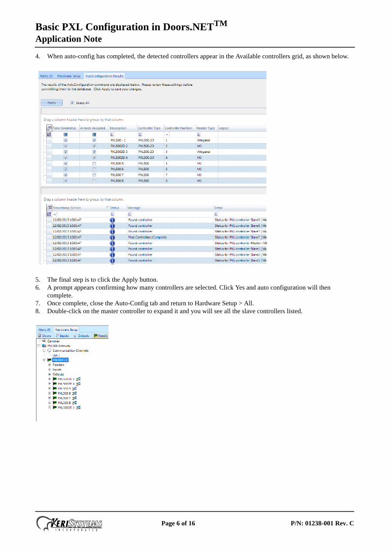
4. When auto-config has completed, the detected controllers appear in the Available controllers grid, as shown below.
5. The final step is to click the Apply button.6. A prompt appears confirming how many controllers are selected. Click Yes and auto configuration will then
complete.7. Once complete, close the Auto-Config tab and return to Hardware Setup > All.8. Double-click on the master controller to expand it and you will see all the slave controllers listed.
Page 6 of 16 P/N: 01238-001 Rev. C
Basic PXL Configuration in Doors.NETTM
Application Note
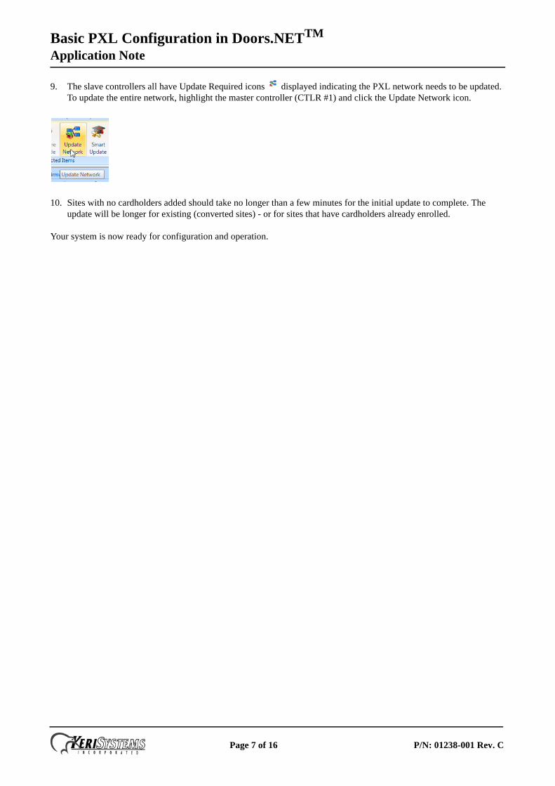
9. The slave controllers all have Update Required icons displayed indicating the PXL network needs to be updated. To update the entire network, highlight the master controller (CTLR #1) and click the Update Network icon.
10. Sites with no cardholders added should take no longer than a few minutes for the initial update to complete. The update will be longer for existing (converted sites) - or for sites that have cardholders already enrolled.
Your system is now ready for configuration and operation.
Page 7 of 16 P/N: 01238-001 Rev. C
Basic PXL Configuration in Doors.NETTM
Application Note
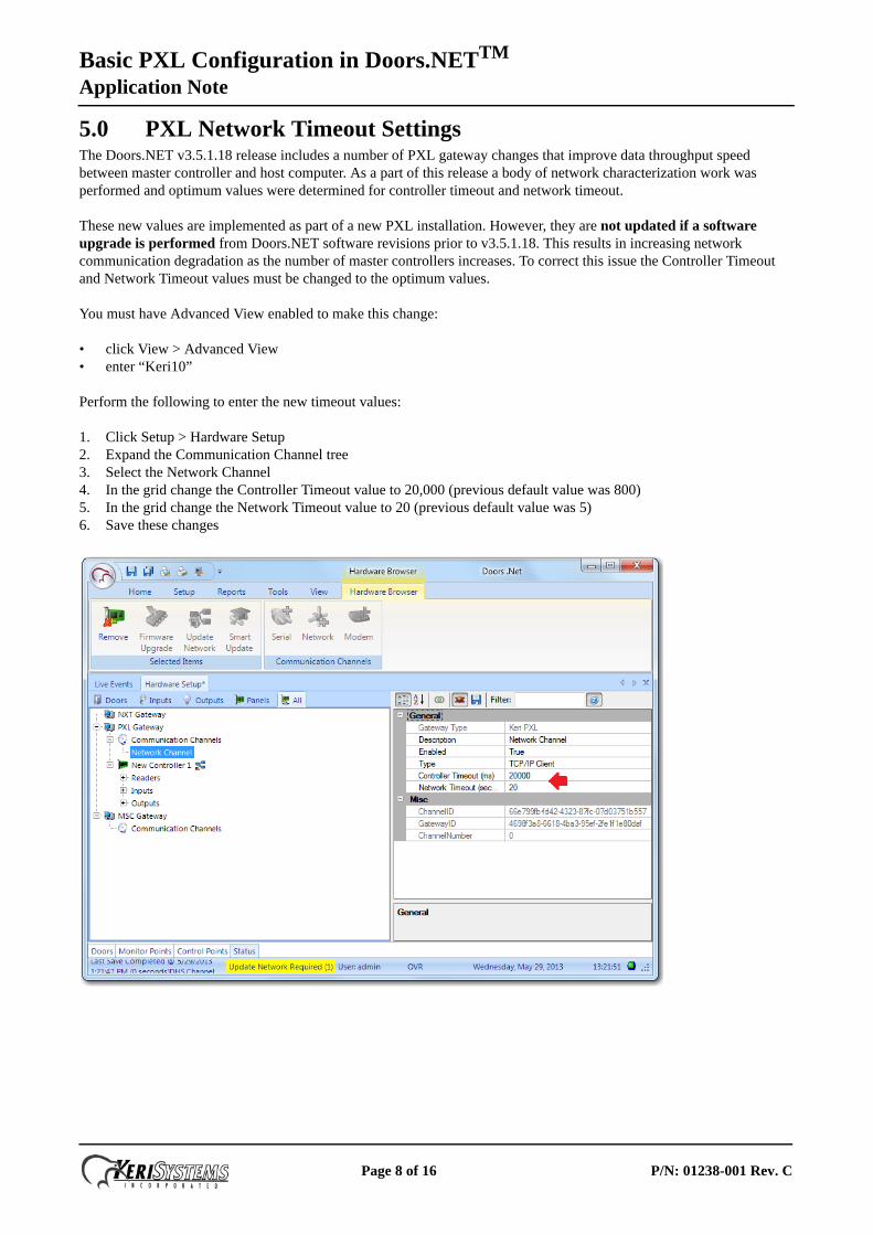
5.0 PXL Network Timeout SettingsThe Doors.NET v3.5.1.18 release includes a number of PXL gateway changes that improve data throughput speed between master controller and host computer. As a part of this release a body of network characterization work was performed and optimum values were determined for controller timeout and network timeout.
These new values are implemented as part of a new PXL installation. However, they are not updated if a software upgrade is performed from Doors.NET software revisions prior to v3.5.1.18. This results in increasing network communication degradation as the number of master controllers increases. To correct this issue the Controller Timeout and Network Timeout values must be changed to the optimum values.
You must have Advanced View enabled to make this change:
• click View > Advanced View• enter “Keri10”
Perform the following to enter the new timeout values:
1. Click Setup > Hardware Setup2. Expand the Communication Channel tree3. Select the Network Channel4. In the grid change the Controller Timeout value to 20,000 (previous default value was 800)5. In the grid change the Network Timeout value to 20 (previous default value was 5)6. Save these changes
Page 8 of 16 P/N: 01238-001 Rev. C
Basic PXL Configuration in Doors.NETTM
Application Note
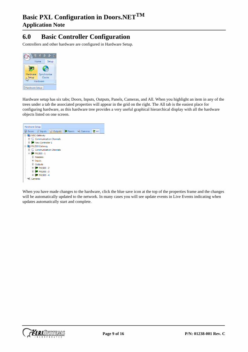
6.0 Basic Controller ConfigurationControllers and other hardware are configured in Hardware Setup.
Hardware setup has six tabs; Doors, Inputs, Outputs, Panels, Cameras, and All. When you highlight an item in any of the trees under a tab the associated properties will appear in the grid on the right. The All tab is the easiest place for configuring hardware, as this hardware tree provides a very useful graphical hierarchical display with all the hardware objects listed on one screen.
When you have made changes to the hardware, click the blue save icon at the top of the properties frame and the changes will be automatically updated to the network. In many cases you will see update events in Live Events indicating when updates automatically start and complete.
Page 9 of 16 P/N: 01238-001 Rev. C
Basic PXL Configuration in Doors.NETTM
Application Note
6.1 Time SchedulesDoors.NET has three default time schedules: Always, Never, and Work Week (M-F 08:00 -17:00). A Time Schedule is a combination of Time Intervals (start and stop times), days of the week, and holidays. They are usually used to restrict when cardholders can gain access or to automatically unlock and lock doors. You can add multiple self-defined Time Schedules to the system.
The Always and Never time schedules are system default schedules and cannot be edited. Work Week (M-F 08:00-17:00) is provided as a courtesy, but the values can be edited or the time schedule, with its intervals, can be removed.
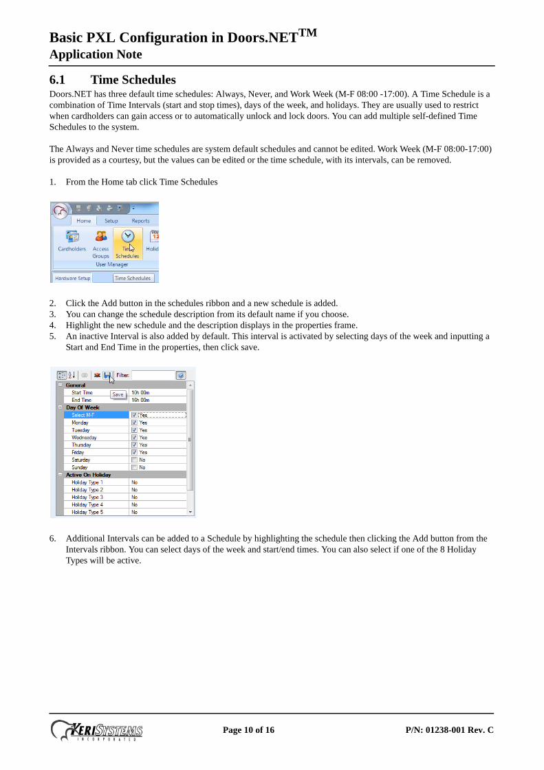
1. From the Home tab click Time Schedules
2. Click the Add button in the schedules ribbon and a new schedule is added.3. You can change the schedule description from its default name if you choose.4. Highlight the new schedule and the description displays in the properties frame.5. An inactive Interval is also added by default. This interval is activated by selecting days of the week and inputting a
Start and End Time in the properties, then click save.
6. Additional Intervals can be added to a Schedule by highlighting the schedule then clicking the Add button from the Intervals ribbon. You can select days of the week and start/end times. You can also select if one of the 8 Holiday Types will be active.
Page 10 of 16 P/N: 01238-001 Rev. C
Basic PXL Configuration in Doors.NETTM
Application Note
6.2 HolidaysHolidays are defined calendar dates which are generally used to de-activate time schedule intervals. You can specify a consecutive range of days which will be classed as one holiday. For example, 24, 25, 26 December could all be defined as a Christmas Holiday.
If a time schedule does not activate, then cardholders who are assigned access groups using these schedules are also inactive, therefore preventing access. Doors which normally auto-unlock will remain locked if the associated time schedule is inactive. The software supports 8 holiday types, each holding up to 32 days. Time schedules can, however, be specified to be active on designated holiday types. Holiday types are used to categorize holidays into different groups.
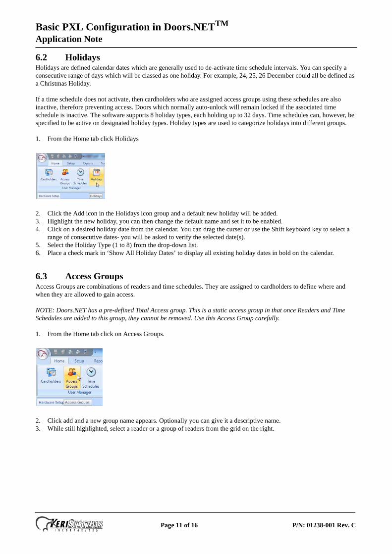
1. From the Home tab click Holidays
2. Click the Add icon in the Holidays icon group and a default new holiday will be added.3. Highlight the new holiday, you can then change the default name and set it to be enabled.4. Click on a desired holiday date from the calendar. You can drag the curser or use the Shift keyboard key to select a
range of consecutive dates- you will be asked to verify the selected date(s).5. Select the Holiday Type (1 to 8) from the drop-down list.6. Place a check mark in ‘Show All Holiday Dates’ to display all existing holiday dates in bold on the calendar.
6.3 Access GroupsAccess Groups are combinations of readers and time schedules. They are assigned to cardholders to define where and when they are allowed to gain access.
NOTE: Doors.NET has a pre-defined Total Access group. This is a static access group in that once Readers and Time Schedules are added to this group, they cannot be removed. Use this Access Group carefully.
1. From the Home tab click on Access Groups.
2. Click add and a new group name appears. Optionally you can give it a descriptive name.3. While still highlighted, select a reader or a group of readers from the grid on the right.
Page 11 of 16 P/N: 01238-001 Rev. C
Basic PXL Configuration in Doors.NETTM
Application Note
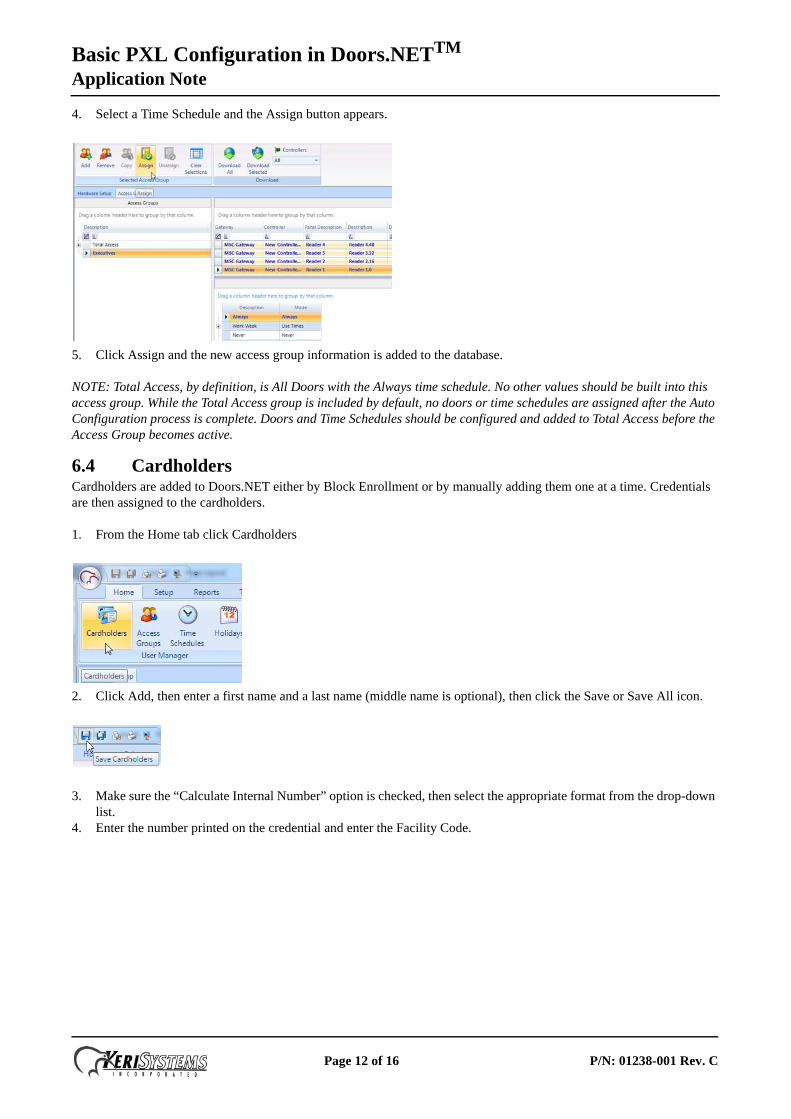
4. Select a Time Schedule and the Assign button appears.
5. Click Assign and the new access group information is added to the database.
NOTE: Total Access, by definition, is All Doors with the Always time schedule. No other values should be built into this access group. While the Total Access group is included by default, no doors or time schedules are assigned after the Auto Configuration process is complete. Doors and Time Schedules should be configured and added to Total Access before the Access Group becomes active.
6.4 CardholdersCardholders are added to Doors.NET either by Block Enrollment or by manually adding them one at a time. Credentials are then assigned to the cardholders.
1. From the Home tab click Cardholders
2. Click Add, then enter a first name and a last name (middle name is optional), then click the Save or Save All icon.
3. Make sure the “Calculate Internal Number” option is checked, then select the appropriate format from the drop-down list.
4. Enter the number printed on the credential and enter the Facility Code.
Page 12 of 16 P/N: 01238-001 Rev. C
Basic PXL Configuration in Doors.NETTM
Application Note
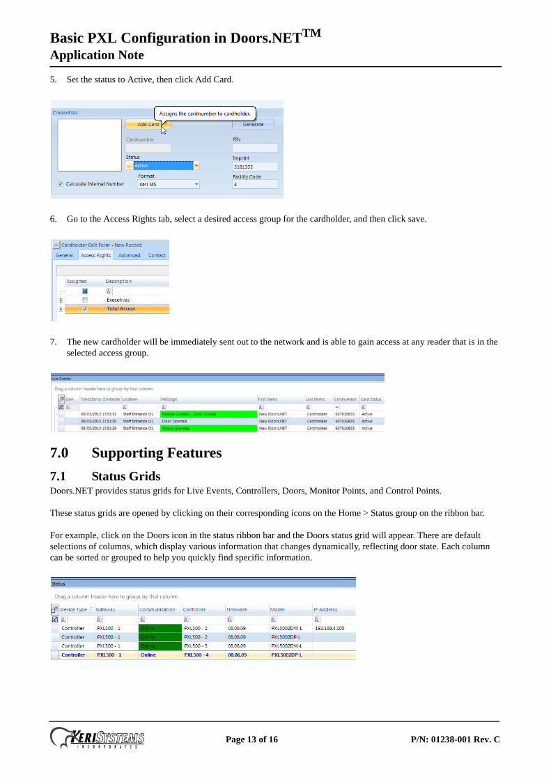
5. Set the status to Active, then click Add Card.
6. Go to the Access Rights tab, select a desired access group for the cardholder, and then click save.
7. The new cardholder will be immediately sent out to the network and is able to gain access at any reader that is in the selected access group.
7.0 Supporting Features
7.1 Status GridsDoors.NET provides status grids for Live Events, Controllers, Doors, Monitor Points, and Control Points.
These status grids are opened by clicking on their corresponding icons on the Home > Status group on the ribbon bar.
For example, click on the Doors icon in the status ribbon bar and the Doors status grid will appear. There are default selections of columns, which display various information that changes dynamically, reflecting door state. Each column can be sorted or grouped to help you quickly find specific information.
Page 13 of 16 P/N: 01238-001 Rev. C
Basic PXL Configuration in Doors.NETTM
Application Note
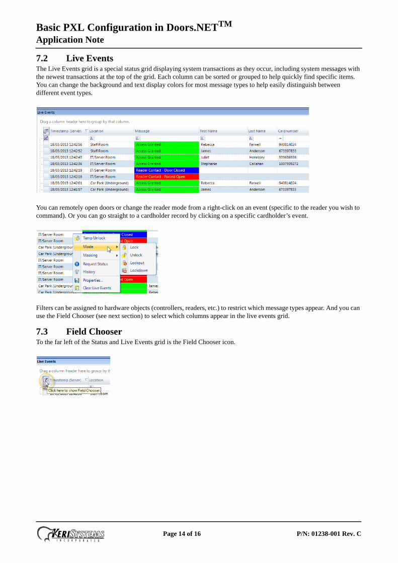
7.2 Live EventsThe Live Events grid is a special status grid displaying system transactions as they occur, including system messages with the newest transactions at the top of the grid. Each column can be sorted or grouped to help quickly find specific items. You can change the background and text display colors for most message types to help easily distinguish between different event types.
You can remotely open doors or change the reader mode from a right-click on an event (specific to the reader you wish to command). Or you can go straight to a cardholder record by clicking on a specific cardholder’s event.
Filters can be assigned to hardware objects (controllers, readers, etc.) to restrict which message types appear. And you can use the Field Chooser (see next section) to select which columns appear in the live events grid.
7.3 Field ChooserTo the far left of the Status and Live Events grid is the Field Chooser icon.
Page 14 of 16 P/N: 01238-001 Rev. C
Basic PXL Configuration in Doors.NETTM
Application Note
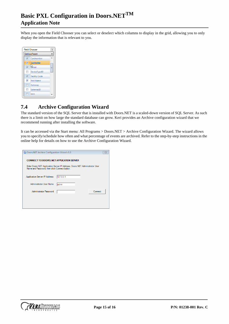
When you open the Field Chooser you can select or deselect which columns to display in the grid, allowing you to only display the information that is relevant to you.
7.4 Archive Configuration WizardThe standard version of the SQL Server that is installed with Doors.NET is a scaled-down version of SQL Server. As such there is a limit on how large the standard database can grow. Keri provides an Archive configuration wizard that we recommend running after installing the software.
It can be accessed via the Start menu: All Programs > Doors.NET > Archive Configuration Wizard. The wizard allows you to specify/schedule how often and what percentage of events are archived. Refer to the step-by-step instructions in the online help for details on how to use the Archive Configuration Wizard.
Page 15 of 16 P/N: 01238-001 Rev. C
Basic PXL Configuration in Doors.NETTM
Application Note
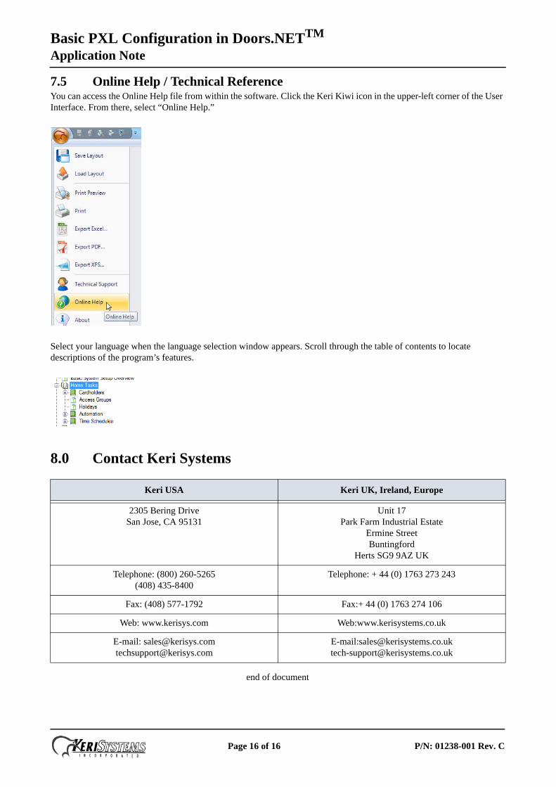
7.5 Online Help / Technical ReferenceYou can access the Online Help file from within the software. Click the Keri Kiwi icon in the upper-left corner of the User Interface. From there, select “Online Help.”
Select your language when the language selection window appears. Scroll through the table of contents to locate descriptions of the program’s features.
8.0 Contact Keri Systems
end of document
Keri USA Keri UK, Ireland, Europe
2305 Bering DriveSan Jose, CA 95131
Unit 17 Park Farm Industrial Estate
Ermine Street Buntingford
Herts SG9 9AZ UK
Telephone: (800) 260-5265(408) 435-8400
Telephone: + 44 (0) 1763 273 243
Fax: (408) 577-1792 Fax:+ 44 (0) 1763 274 106
Web: www.kerisys.com Web:www.kerisystems.co.uk
E-mail: [email protected]@kerisys.com
E-mail:[email protected]@kerisystems.co.uk
Page 16 of 16 P/N: 01238-001 Rev. C