Embed Size (px)
Citation preview
Basic Principles of Fiber Optics
httpwwwcorningcablesystemscomwebcollege
fibertutorialnsffibmanOpenForm
Copyright copy2006 Corning Incorporated
Basic Principles of Fiber Optics
mdash 2 20 mdash
Table of Contents Introduction 3
What is Fiber Optics 4 Fiber Benefits 4
Long Distance Signal Transmission 4 Large Bandwidth Light Weight and Small Diameter 4 Long Lengths 5 Easy Installation and Upgrades 5 Non-Conductivity 5 Security 6 Designed for Future Applications Needs 6
Key Points in Fiber History 6 Check Your Understanding 7 Bibliography 7
Basic Principles of Operation 8 The Information Transmision Sequence 8 Cross Section of a Typical Fiber 8 Types of Fiber 9 Check Your Understanding 10
Applied Principles of Operation 10 Index of Refraction (IOR) 10 Total Internal Refraction 11 Acceptance Cone 11 Check Your Understanding 11
Optical Fiber Parameters 12 Wavelength 12 Window 13 Frequency 13 Attenuation 13 Intrinsic Attenuation 14
Scattering 14 Absorption 14
Extrinsic Attenuation 15 Macrobending 15 Microbending 15
Dispersion 16 Bandwidth 16 Check Your Understanding 17
Fiber Manufacturing 17 Laydown 18 Consolidation 18 Draw 18 Check Your Understanding 19
Basic Principles of Fiber Optics
mdash 3 20 mdash
Introduction
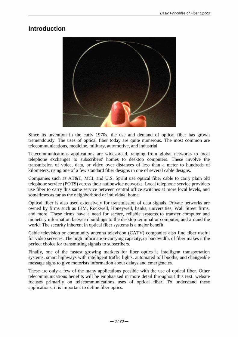
Since its invention in the early 1970s the use and demand of optical fiber has grown
tremendously The uses of optical fiber today are quite numerous The most common are
telecommunications medicine military automotive and industrial
Telecommunications applications are widespread ranging from global networks to local
telephone exchanges to subscribers homes to desktop computers These involve the
transmission of voice data or video over distances of less than a meter to hundreds of
kilometers using one of a few standard fiber designs in one of several cable designs
Companies such as ATampT MCI and US Sprint use optical fiber cable to carry plain old
telephone service (POTS) across their nationwide networks Local telephone service providers
use fiber to carry this same service between central office switches at more local levels and
sometimes as far as the neighborhood or individual home
Optical fiber is also used extensively for transmission of data signals Private networks are
owned by firms such as IBM Rockwell Honeywell banks universities Wall Street firms
and more These firms have a need for secure reliable systems to transfer computer and
monetary information between buildings to the desktop terminal or computer and around the
world The security inherent in optical fiber systems is a major benefit
Cable television or community antenna television (CATV) companies also find fiber useful
for video services The high information-carrying capacity or bandwidth of fiber makes it the
perfect choice for transmitting signals to subscribers
Finally one of the fastest growing markets for fiber optics is intelligent transportation
systems smart highways with intelligent traffic lights automated toll booths and changeable
message signs to give motorists information about delays and emergencies
These are only a few of the many applications possible with the use of optical fiber Other
telecommunications benefits will be emphasized in more detail throughout this text website
focuses primarily on telecommunications uses of optical fiber To understand these
applications it is important to define fiber optics
Basic Principles of Fiber Optics
mdash 4 20 mdash
What is Fiber Optics
In its simplest terms fiber optics is a medium for carrying information from one point to
another in the form of light Unlike the copper form of transmission fiber optics is not
electrical in nature
A basic fiber optic system consists of a transmitting device which generates the light signal
an optical fiber cable which carries the light and a receiver which accepts the light signal
transmitted The fiber itself is passive and does not contain any active generative properties
Corning Cable Systems manufactures and sells those components considered to be part of the
passive fiber transmission subsystem ie not active electronic components
Fiber Benefits
Optical fiber systems have many advantages over metallic-based communication systems
These advantages include
Long Distance Signal Transmission
The low attenuation and superior signal integrity found in optical systems allow much longer
intervals of signal transmission than metallic-based systems While single-line voice-grade
copper systems longer than a couple of kilometers (12 miles) require in-line signal repeater
for satisfactory performance it is not unusual for optical systems to go over 100 kilometers
(km) or about 62 miles with no active or passive processing Emerging technologies promise
even greater distances in the future
The optical fiber cable in the foreground has the equivalent information-carrying capacity of the copper cable in the background
Large Bandwidth Light Weight and Small Diameter
While todays applications require an ever-increasing amount of bandwidth it is important to
consider the space constraints of many end-users It is commonplace to install new cabling
within existing duct systems The relatively small diameter and light weight of optical cables
Basic Principles of Fiber Optics
mdash 5 20 mdash
makes such installations easy and practical and saves valuable conduit space in these
environments
Long Lengths
Long continuous lengths also provide advantages for installers and end-users Small
diameters make it practical to manufacture and install much longer lengths than for metallic
cables twelve-kilometer (12 km) continuous optical cable lengths are common Corning
Cable Systems manufactures continuous single-mode cable lengths up to 12 km with a 96-
inch reel size being the primary limiting factor
Multimode cable lengths can be 4 km or more although most standards require a maximum
length of 2 km or less Multimode cable lengths are based on industry demand (Single-mode
and multimode fibers will be covered in detail later in this text)
Easy Installation and Upgrades
Long lengths make optical cable installation much easier and less expensive Optical fiber
cables can be installed with the same equipment that is used to install copper and coaxial
cables with some modifications due to the small size and limited pull tension and bend radius
of optical cables
Optical cables can typically be installed in duct systems in spans of 6000 meters or more
depending on the ducts condition layout of the duct system and installation technique The
longer cables can be coiled at an intermediate point and pulled farther into the duct system as
necessary
System designers typically plan optical systems that will meet growth needs for a 15- to 20-
year span Although sometimes difficult to predict growth can be accommodated by
installing spare fibers for future requirements Installation of spare fibers today is more
economical than installing additional cables later
The dielectric nature of optical fiber can eliminate the dangers found in areas of high lightning-strike incidence
Non-Conductivity
Another advantage of optical fibers is their dielectric nature Since optical fiber has no
metallic components it can be installed in areas with electromagnetic interference (EMI)
including radio frequency interference (RFI) Areas with high EMI include utility lines
power-carrying lines and railroad tracks All-dielectric cables are also ideal for areas of high
lightning-strike incidence
Basic Principles of Fiber Optics
mdash 6 20 mdash
Security
Unlike metallic-based systems the dielectric nature of optical fiber makes it impossible to
remotely detect the signal being transmitted within the cable The only way to do so is by
actually accessing the optical fiber itself Accessing the fiber requires intervention that is
easily detectable by security surveillance These circumstances make fiber extremely
attractive to governmental bodies banks and others with major security concerns
Designed for Future Applications Needs
Fiber optics is affordable today as electronics prices fall and optical cable pricing remains
low In many cases fiber solutions are less costly than copper
As bandwidth demands increase rapidly with technological advances fiber will continue to
play a vital role in the long-term success of telecommunications
Key Points in Fiber History
Most people remember Paul Reveres one if by land and two if by sea from early American
history He used lanterns to communicate information Although not sophisticated this was
an early example of optical communication
In 1870 British physicist John Tyndal gave us another example Tyndal set up a tank of water
with a pipe that ran out one side He allowed the water to flow from the pipe and then shone a
bright light from inside the tank into the water stream As the water fell an arc of light
followed the water down This demonstrated total internal reflection a principle that will be
discussed in more detail later
In 1880 Alexander Graham Bell invented the photophone Bell considered this a greater
discovery than his previous invention the telephone With the photophone Bell would speak
into a microphone which would cause a mirror to vibrate The suns light would strike the
mirror and the vibration of the mirror would transmit the light across an open distance of
about 200 meters (656 feet) The receivers mirror would receive the light and cause a
selenium crystal to vibrate and the noise would come out on the other end (See Figure 1
below) Although the photophone was successful in allowing conversation over open space it
had a few drawbacks it did not work well at night in the rain or if someone walked between
the signal and the receiver Eventually Bell gave up on this idea
Figure 1
Basic Principles of Fiber Optics
mdash 7 20 mdash
It wasnt until the late 1950s that the laser was invented This device was a finely-controlled
beam of light that could transmit information over long distances Unfortunately the same
drawbacks experienced by Alexander Graham Bell also plagued the laser Although it could
be used at night it didnt work during rain fog or any time a building was erected between
the sender and the receiver
Dr Robert Maurer Peter Schultz and Donald Keck of Corning Incorporated in Corning New
York came up with the first low loss optical fiber with less than 20 dBkm (decibels per
kilometer) loss (Today single-mode premium grade fiber is sold with specifications of 025
dBkm or better)
In 1977 Corning joined forces with another technological giant Siemens Corporation to
form Corning Cable Systems Cornings extensive work with fiber coupled with Siemens
cabling technology helped launch a new era in optical fiber cable and associated products
Today Corning Cable Systems is a world leader in the manufacture of fiber optic cabling
system products for voice data and video communications applications
Check Your Understanding
Would you like to see how much youve learned
1 In what decade did optical fiber communications become commercially viable
1870
1950
1970
1980
2 Which of the following is a good example of an optical fiber application for
telecommunications
Local or long-distance telephone communications
Medical instruments for orthoscopic surgery
Missile guidance and target tracking
3 Which of the following is not true about optical fiber transmission systems
Can be used for voice or data and video
Are almost always more expensive than copper
Easy to install and upgrade
Are virtually immune to electromagnetic and radio-frequency interference
Bibliography
Introduction to Basic Fiber Optics
Session Outline Corning Cable Systems 1994
Just the Facts
Corning Incorporated Corning New York 1993
Jeff Englebert et alOptical Fiber and Cable for Telecommunications
Corning Cable Systems 1996
TR-07-S Hands-On Fiber Optic Installation for Local Area Networks
Corning Cable Systems Hickory North Carolina 1989
Jeff Hecht Understanding Fiber Optics
Howard W Sams amp Company Carmel Indiana 1987
Basic Principles of Fiber Optics
mdash 8 20 mdash
Basic Principles of Operation
Figure 2
The Information Transmision Sequence
As depicted above information (voice data or video) is encoded into electrical signals At
the light source these electrical signals are converted into light signals
It is important to note that fiber has the capability to carry either analog or digital signals
Many people believe that fiber can transmit only digital signals due to the onoff binary
characteristic of the light source The intensity of the light and the frequency at which the
intensity changes can be used for AM and FM analog transmission
Once the signals are converted to light they travel down the fiber until they reach a detector
which changes the light signals back into electrical signals This area from light source to
detector constitutes the passive transmission subsystem ie that part of the system
manufactured and sold by Corning Cable Systems
Finally the electrical signals are decoded into information in the form of voice data or video
Cross Section of a Typical Fiber
Figure 3
Basic Principles of Fiber Optics
mdash 9 20 mdash
Optical fiber for telecommunications consists of three components core cladding amp coating
The core is the central region of an optical fiber through which light is transmitted In general
the telecommunications industry uses sizes from 83 micrometer (microm) to 625 micrometers
The standard telecommunications core sizes in use today are 83 microm (single-mode) 50 microm
(multimode) and 625 microm (multimode) (Single-mode and multimode will be discussed
shortly) The diameter of the cladding surrounding each of these cores is 125 microm Core sizes
of 85 microm and 100 microm have been used in early applications but are not typically used today
To put these sizes into perspective compare them to a human hair which is approximately 70
microm or 0003 inch
The core and cladding are manufactured together as a single piece of silica glass with slightly
different compositions and cannot be separated from one another The glass does not have a
hole in the core but is completely solid throughout
The third section of an optical fiber is the outer protective coating This coating is typically an
ultraviolet (UV) light-cured acrylate applied during the manufacturing process to provide
physical and environmental protection for the fiber During the installation process this
coating is stripped away from the cladding to allow proper termination to an optical
transmission system
The coating size can vary but the standard sizes are 250 microm or 900 microm The 250 microm coating
takes less space in larger outdoor cables The 900 microm coating is larger and more suitable for
smaller indoor cables
Types of Fiber
Once light enters an optical fiber it travels in a stable state called a mode There can be from
one to hundreds of modes depending on the type of fiber Each mode carries a portion of the
light from the input signal
Generally speaking the number of modes in a fiber is a function of the relationship between
core diameter numerical aperture and wavelength which will be discussed later in the text
Figure 4
Every telecommunications fiber falls into one of two categories single-mode or multimode
It is impossible to distinguish between single-mode and multimode fiber with the naked eye
There is no difference in outward appearance only in core size Both fiber types act as a
transmission medium for light but they operate in different ways have different
characteristics and serve different applications
Single-Mode (SM) fiber allows for only one pathway or mode of light to travel within the
fiber The core size is typically 83 microm Single-mode fibers are used in applications where low
signal loss and high data rates are required such as on long spans where repeateramplifier
spacing needs to be maximized
Basic Principles of Fiber Optics
mdash 10 20 mdash
Multimode (MM) fiber allows more than one mode of light Common MM core sizes are 50
microm and 625 microm Multimode fiber is better suited for shorter distance applications Where
costly electronics are heavily concentrated the primary cost of the system does not lie with
the cable In such a case MM fiber is more economical because it can be used with
inexpensive connectors and LED transmitters making the total system cost lower This makes
MM fiber the ideal choice for short distance lower bandwidth applications
Check Your Understanding
Would you like to see how much youve learned
1 What purpose does the core of an optical fiber serve
It protects the fiber from the environment
It carries light through the fiber
It separates the cladding and the coating
2 Which of the following is NOT true of single-mode fiber
It carries more information than multimode fiber
Its core is smaller than multimode fiber
It is hollow in the center
3 At installation which of the following is NOT true about optical fiber
The cladding and coating are stripped away
The fiber has the ability to carry either analog or digital signals
Light signals must enter the fiber within the acceptance cone to propagate
Applied Principles of Operation
Index of Refraction (IOR)
The index of refraction (IOR) is a way of measuring the speed of light in a material Light
travels fastest in a vacuum such as outer space The actual speed of light in a vacuum is
300000 kilometers per second or 186000 miles per second
Index of Refraction is calculated by dividing the speed of light in a vacuum by the speed of
light in some other medium
The Index of Refraction of a vacuum by definition has a value of 1
For the sake of simplicity typical values are provided here in Figure 5 Notice that the typical
value for the cladding of an optical fiber is 146 The core value is 148 The larger the index
of refraction the more slowly light travels in that medium
Figure 5
Basic Principles of Fiber Optics
mdash 11 20 mdash
Total Internal Refraction
When a light ray traveling in one material hits a different material and reflects back into the
original material without any loss of light total internal refraction occurs
Since the core and cladding are constructed from different compositions of glass
theoretically light entering the core is confined to the boundaries of the core because it
reflects back whenever it hits the cladding For total internal reflection to occur the index of
refraction of the core must be higher than that of the cladding
Acceptance Cone
As mentioned earlier electrical signals are converted to light signals before they enter an
optical fiber To ensure that the signals reflect and travel correctly through the core the light
must enter the core through an imaginary acceptance cone (See Figure 7 below) The size of
this acceptance cone is a function of the refractive index difference between the core and the
cladding
In simpler terms there is a maximum angle from the fiber axis at which light may enter the
fiber so that it will propagate or travel in the core of the fiber The sine of this maximum
angle is the numerical aperture (NA) of the fiber Fiber with a larger NA requires less
precision to splice and work with than fiber with a smaller NA Single-mode fiber has a small
NA
Check Your Understanding
Would you like to see how much youve learned
1 Which of the following is true of the index of refraction
It is a way of measuring the speed of light in a material
It is calculated by dividing the speed of light in some medium by the speed of light
in a vacuum
When calculated it shows that the fastest light speed occurs in air
2 Total internal reflection is
Reflection that occurs when a light ray traveling in one material hits another
material and reflects back into the original material without any loss of light
Basic Principles of Fiber Optics
mdash 12 20 mdash
Complete meditation without interruption
Reflection that occurs when the refractive index of the core is lower than the
cladding
Optical Fiber Parameters
As with any type of transmission system there are certain parameters that affect the systems
operation
Wavelength
Light that can be seen by the unaided human eye is said to be in the visible spectrum In the
visible spectrum wavelength can be described as the color of light
To put this into perspective take a look at Figure 8 Notice that the colors of the rainbow -
red orange yellow green blue (indigo not shown) and violet fall within the visible
spectrum
Figure 8
Basic Principles of Fiber Optics
mdash 13 20 mdash
Optical fiber transmission uses wavelengths which are above the visible light spectrum and
thus undetectable to the unaided eye Typical optical transmission wavelengths are 850
nanometers (nm) 1310 nm and 1550 nm
Both lasers and LEDs (light-emitting diodes) are used to transmit light through optical fiber
Lasers are usually used for 1310 or 1550 nanometer single-mode applications LEDs are
used for 850 or 1300 nanometer multimode applications
Safety note Never look into the end of a fiber which may have a laser coupled to it Laser
light is invisible and can damage the eyes Viewing it directly does not cause pain The iris of
the eye will not close involuntarily as when viewing a bright light consequently serious
damage to the retina of the eye is possible Should accidental exposure to laser light be
suspected an eye examination should be arranged immediately
Window
There are ranges of wavelengths at which the fiber operates best Each range is known as an
operating window Each window is centered around the typical operational wavelength
Figure 9
These wavelengths were chosen because they best match the transmission properties of
available light sources with the transmission qualities of optical fiber
Frequency
The frequency of a system is the speed of modulation of the digital or analog output of the
light source in other words the number of pulses per second emitted from the light source
Frequency is measured in units of hertz (Hz) where 1 hertz is equal to 1 pulse or cycle per
second (Figure 10) A more practical measurement for optical communications is megahertz
(MHz) or millions of pulses per second
Figure 10
Attenuation
Attenuation is the loss of optical power as light travels down a fiber It is measured in decibels
(dBkm) Over a set distance a fiber with a lower attenuation will allow more power to reach
its receiver than a fiber with higher attenuation
Basic Principles of Fiber Optics
mdash 14 20 mdash
While low-loss optical systems are always desirable it is possible to lose a large portion of
the initial signal power without significant problems A loss of 50 of initial power is equal
to a 30 dB loss Any time fibers are joined together there will be some loss Losses for fusion
splicing and for mechanical splicing are typically 02 dB or less
Attenuation can be caused by several factors but is generally placed in one of two categories
intrinsic or extrinsic
Intrinsic Attenuation
Intrinsic attenuation occurs due to something inside or inherent to the fiber It is caused by
impurities in the glass during the manufacturing process As precise as manufacturing is there
is no way to eliminate all impurities though technological advances have caused attenuation
to decrease dramatically since the first optical fiber in 1970
When a light signal hits an impurity in the fiber one of two things will occur it will scatter or
it will be absorbed
Scattering
Rayleigh scattering accounts for the majority (about 96) of attenuation in optical fiber
Light travels in the core and interacts with the atoms in the glass The light waves elastically
collide with the atoms and light is scattered as a result
Rayleigh scattering is the result of these elastic collisions between the light wave and the
atoms in the fiber If the scattered light maintains an angle that supports forward travel within
the core no attenuation occurs If the light is scattered at an angle that does not support
continued forward travel the light is diverted out of the core and attenuation occurs
Figure 11
Some scattered light is reflected back toward the light source (input end) This is a property
that is used in an Optical Time Domain Reflectometer (OTDR) to test fibers This same
principle applies to analyzing loss associated with localized events in the fiber such as
splices
Absorption
The second type of intrinsic attenuation in fiber is absorption Absorption accounts for 3-5
of fiber attenuation This phenomenon causes a light signal to be absorbed by natural
impurities in the glass and converted to vibrational energy or some other form of energy
(Figure 12)
Unlike scattering absorption can be limited by controlling the amount of impurities during
the manufacturing process
Basic Principles of Fiber Optics
mdash 15 20 mdash
Figure 12
Extrinsic Attenuation
The second category of attenuation is extrinsic attenuation Extrinsic attenuation can be
caused by two external mechanisms macrobending or microbending Both cause a reduction
of optical power
Macrobending
If a bend is imposed on an optical fiber strain is placed on the fiber along the region that is
bent The bending strain will affect the refractive index and the critical angle of the light ray
in that specific area As a result light traveling in the core can refract out and loss occurs
(Figure 13)
A macrobend is a large-scale bend that is visible for example a fiber wrapped around a
persons finger This loss is generally reversible once bends are corrected
To prevent macrobends all optical fiber (and optical fiber cable) has a minimum bend radius
specification that should not be exceeded This is a restriction on how much bend a fiber can
withstand before experiencing problems in optical performance or mechanical reliability The
rule of thumb for minimum bend radius is 1 12 for bare single-mode fiber 10 times the
cables outside diameter (OD) for non-armored cable and 15 times the cables OD for
armored cable
Figure 13
Microbending
The second extrinsic cause of attenuation is a microbend This is a small-scale distortion
generally indicative of pressure on the fiber (See Figure 14 below) Microbending may be
related to temperature tensile stress or crushing force Like macrobending microbending
will cause a reduction of optical power in the glass
Microbending is very localized and the bend may not be clearly visible upon inspection With
bare fiber microbending may be reversible in the cabling process it may not
Basic Principles of Fiber Optics
mdash 16 20 mdash
Figure 14
Dispersion
Dispersion is the spreading of a light pulse as it travels down a fiber (See Figure 15) As
the pulses spread or broaden they tend to overlap and are no longer distinguishable by the
receiver as 0s and 1s Light pulses launched close together (high data rates) that spread too
much (high dispersion) result in errors and loss of information
Chromatic dispersion occurs as a result of the range of wavelengths in the light source Light
from lasers and LEDs consists of a range of wavelengths Each of these wavelengths travels at
a slightly different speed Over distance the varying wavelength speeds cause the light pulse
to spread in time This is of most importance in single-mode applications
Modal dispersion is significant in multimode applications where the various modes of light
traveling down the fiber arrive at the receiver at different times causing a spreading effect
Figure 15
Pulse width is measured at full width-half maximum in other words the full width of the
pulse at half the maximum pulse height Dispersion limits how fast or how much
information can be sent over an optical fiber
There are other effects of dispersion but further discussion is beyond the scope of this text
For more in-depth reading please consult the bibliography at the end of this publication
Bandwidth
In simplest terms bandwidth is the amount of information a fiber can carry so that every pulse
is distinguishable by the receiver at the end (Figure 16)
Basic Principles of Fiber Optics
mdash 17 20 mdash
Figure 16
As discussed in the previous section dispersion causes light pulses to spread The spreading
of these light pulses causes them to merge together At a certain distance and frequency the
pulses become unreadable by the receiver The multiple pathways of a multimode fiber cause
this overlap to be much greater than for single-mode fiber These different paths have
different lengths which cause each mode of light to arrive at a different time
System bandwidth is measured in megahertz (MHz) at one km In general when a systems
bandwidth is 200 MHzmiddotkm it means that 200 million pulses of light per second will travel
down 1 km (1000 meters) of fiber and each pulse will be distinguishable by the receiver
Check Your Understanding
Would you like to see how much youve learned
1 In optical fiber systems what are the typical wavelengths of operation
400 nm 455 nm 490 nm
620 nm 750 nm 800 nm
850 nm 1310 nm 1550 nm
2 What is an optical window
A glass object on the side of a building
A range of wavelengths at which fiber best operates
The moment in time when fiber became a commercially-viable enterprise
3 Which of the following is not true of attenuation
It is the loss of optical power as light travels down a fiber
It may be induced by scattering absorbing macrobending and microbending
It is measured in nanometers
4 What is bandwidth
A measure of the information-carrying capacity of an optical fiber
The side-to-side measurement of a wedding ring
A term used to express the total loss of an optical system
Fiber Manufacturing
There are several ways to manufacture optical fiber but this text will concentrate on the
method developed patented and used by the former Corning Glass Works now Corning
Incorporated
This method called Outside Vapor Deposition or OVD has three steps or phases laydown
consolidation and draw
Basic Principles of Fiber Optics
mdash 18 20 mdash
Laydown
In the laydown step a soot preform is made from ultrapure vapors of silicon tetrachloride and
germanium tetrachloride The vapors travel through a traversing burner and react in the flame
to form soot particles of silica and germania
Figure 17
The OVD process is distinguished by the method of depositing the soot These particles are
deposited on the surface of a rotating target rod The core material is deposited first followed
by the pure silica cladding Since both core and cladding raw materials are vapor-deposited
the entire preform is extremely pure
Consolidation
When deposition is complete the target rod is removed from the center of the porous preform
and the preform is placed into a consolidation furnace During the consolidation process the
water vapor is removed from the preform This high-temperature consolidation step sinters the
preform into a solid dense transparent glass blank The hole left by the target rod is fused
solid by the extremely high temperature of the draw furnace
Draw
The finished glass preform is placed in a draw tower and drawn into a continuous strand of
glass fiber First the blank is lowered into the top of the draw furnace
Basic Principles of Fiber Optics
mdash 19 20 mdash
Figure 18
The tip of the blank is heated until a piece of molten glass called a gob begins to fall from
the blank like hot taffy It pulls a thin strand of glass the beginning of an optical fiber
The fiber goes through a precise on-line diameter monitor to ensure specified outside
diameter Next coatings are applied and cured using ultraviolet lamps
At the bottom of the draw the fiber is wound on spools Each fiber is assigned a unique
identification number that encodes all relevant manufacturing data including raw materials
and manufacturing equipment
Note Extensive text and graphics in this Fiber Manufacturing section are used with
permission of Corning Communications
Check Your Understanding
Would you like to see how much youve learned
1 What are the three steps of fiber manufacture using the Outside Vapor Deposition (OVD)
method
Burner vapor fuel
Laydown consolidation draw
Gas glass spool
2 Which of the following is NOT true about the laydown stage of OVD fiber manufacture
A rotating target rod collects soot deposited from the burner
Basic Principles of Fiber Optics
mdash 20 20 mdash
The soot forms a preform
The preform is highly impure until it reaches the consolidation phase
3 Which of the following is NOT true about the consolidation stage of fiber manufacture
The removal of the target rod causes the core of the fiber to be hollow
Water vapor is removed from the preform
The white preform becomes a solid dense transparent glass blank
4 Which of the following is NOT true about the draw stage of fiber manufacture
The glass preform is drawn into a continuous piece of glass fiber
Fiber diameters are measured on-line
Coatings are applied and cured using infrared lamps

Basic Principles of Fiber Optics
mdash 2 20 mdash
Table of Contents Introduction 3
What is Fiber Optics 4 Fiber Benefits 4
Long Distance Signal Transmission 4 Large Bandwidth Light Weight and Small Diameter 4 Long Lengths 5 Easy Installation and Upgrades 5 Non-Conductivity 5 Security 6 Designed for Future Applications Needs 6
Key Points in Fiber History 6 Check Your Understanding 7 Bibliography 7
Basic Principles of Operation 8 The Information Transmision Sequence 8 Cross Section of a Typical Fiber 8 Types of Fiber 9 Check Your Understanding 10
Applied Principles of Operation 10 Index of Refraction (IOR) 10 Total Internal Refraction 11 Acceptance Cone 11 Check Your Understanding 11
Optical Fiber Parameters 12 Wavelength 12 Window 13 Frequency 13 Attenuation 13 Intrinsic Attenuation 14
Scattering 14 Absorption 14
Extrinsic Attenuation 15 Macrobending 15 Microbending 15
Dispersion 16 Bandwidth 16 Check Your Understanding 17
Fiber Manufacturing 17 Laydown 18 Consolidation 18 Draw 18 Check Your Understanding 19
Basic Principles of Fiber Optics
mdash 3 20 mdash
Introduction
Since its invention in the early 1970s the use and demand of optical fiber has grown
tremendously The uses of optical fiber today are quite numerous The most common are
telecommunications medicine military automotive and industrial
Telecommunications applications are widespread ranging from global networks to local
telephone exchanges to subscribers homes to desktop computers These involve the
transmission of voice data or video over distances of less than a meter to hundreds of
kilometers using one of a few standard fiber designs in one of several cable designs
Companies such as ATampT MCI and US Sprint use optical fiber cable to carry plain old
telephone service (POTS) across their nationwide networks Local telephone service providers
use fiber to carry this same service between central office switches at more local levels and
sometimes as far as the neighborhood or individual home
Optical fiber is also used extensively for transmission of data signals Private networks are
owned by firms such as IBM Rockwell Honeywell banks universities Wall Street firms
and more These firms have a need for secure reliable systems to transfer computer and
monetary information between buildings to the desktop terminal or computer and around the
world The security inherent in optical fiber systems is a major benefit
Cable television or community antenna television (CATV) companies also find fiber useful
for video services The high information-carrying capacity or bandwidth of fiber makes it the
perfect choice for transmitting signals to subscribers
Finally one of the fastest growing markets for fiber optics is intelligent transportation
systems smart highways with intelligent traffic lights automated toll booths and changeable
message signs to give motorists information about delays and emergencies
These are only a few of the many applications possible with the use of optical fiber Other
telecommunications benefits will be emphasized in more detail throughout this text website
focuses primarily on telecommunications uses of optical fiber To understand these
applications it is important to define fiber optics
Basic Principles of Fiber Optics
mdash 4 20 mdash
What is Fiber Optics
In its simplest terms fiber optics is a medium for carrying information from one point to
another in the form of light Unlike the copper form of transmission fiber optics is not
electrical in nature
A basic fiber optic system consists of a transmitting device which generates the light signal
an optical fiber cable which carries the light and a receiver which accepts the light signal
transmitted The fiber itself is passive and does not contain any active generative properties
Corning Cable Systems manufactures and sells those components considered to be part of the
passive fiber transmission subsystem ie not active electronic components
Fiber Benefits
Optical fiber systems have many advantages over metallic-based communication systems
These advantages include
Long Distance Signal Transmission
The low attenuation and superior signal integrity found in optical systems allow much longer
intervals of signal transmission than metallic-based systems While single-line voice-grade
copper systems longer than a couple of kilometers (12 miles) require in-line signal repeater
for satisfactory performance it is not unusual for optical systems to go over 100 kilometers
(km) or about 62 miles with no active or passive processing Emerging technologies promise
even greater distances in the future
The optical fiber cable in the foreground has the equivalent information-carrying capacity of the copper cable in the background
Large Bandwidth Light Weight and Small Diameter
While todays applications require an ever-increasing amount of bandwidth it is important to
consider the space constraints of many end-users It is commonplace to install new cabling
within existing duct systems The relatively small diameter and light weight of optical cables
Basic Principles of Fiber Optics
mdash 5 20 mdash
makes such installations easy and practical and saves valuable conduit space in these
environments
Long Lengths
Long continuous lengths also provide advantages for installers and end-users Small
diameters make it practical to manufacture and install much longer lengths than for metallic
cables twelve-kilometer (12 km) continuous optical cable lengths are common Corning
Cable Systems manufactures continuous single-mode cable lengths up to 12 km with a 96-
inch reel size being the primary limiting factor
Multimode cable lengths can be 4 km or more although most standards require a maximum
length of 2 km or less Multimode cable lengths are based on industry demand (Single-mode
and multimode fibers will be covered in detail later in this text)
Easy Installation and Upgrades
Long lengths make optical cable installation much easier and less expensive Optical fiber
cables can be installed with the same equipment that is used to install copper and coaxial
cables with some modifications due to the small size and limited pull tension and bend radius
of optical cables
Optical cables can typically be installed in duct systems in spans of 6000 meters or more
depending on the ducts condition layout of the duct system and installation technique The
longer cables can be coiled at an intermediate point and pulled farther into the duct system as
necessary
System designers typically plan optical systems that will meet growth needs for a 15- to 20-
year span Although sometimes difficult to predict growth can be accommodated by
installing spare fibers for future requirements Installation of spare fibers today is more
economical than installing additional cables later
The dielectric nature of optical fiber can eliminate the dangers found in areas of high lightning-strike incidence
Non-Conductivity
Another advantage of optical fibers is their dielectric nature Since optical fiber has no
metallic components it can be installed in areas with electromagnetic interference (EMI)
including radio frequency interference (RFI) Areas with high EMI include utility lines
power-carrying lines and railroad tracks All-dielectric cables are also ideal for areas of high
lightning-strike incidence
Basic Principles of Fiber Optics
mdash 6 20 mdash
Security
Unlike metallic-based systems the dielectric nature of optical fiber makes it impossible to
remotely detect the signal being transmitted within the cable The only way to do so is by
actually accessing the optical fiber itself Accessing the fiber requires intervention that is
easily detectable by security surveillance These circumstances make fiber extremely
attractive to governmental bodies banks and others with major security concerns
Designed for Future Applications Needs
Fiber optics is affordable today as electronics prices fall and optical cable pricing remains
low In many cases fiber solutions are less costly than copper
As bandwidth demands increase rapidly with technological advances fiber will continue to
play a vital role in the long-term success of telecommunications
Key Points in Fiber History
Most people remember Paul Reveres one if by land and two if by sea from early American
history He used lanterns to communicate information Although not sophisticated this was
an early example of optical communication
In 1870 British physicist John Tyndal gave us another example Tyndal set up a tank of water
with a pipe that ran out one side He allowed the water to flow from the pipe and then shone a
bright light from inside the tank into the water stream As the water fell an arc of light
followed the water down This demonstrated total internal reflection a principle that will be
discussed in more detail later
In 1880 Alexander Graham Bell invented the photophone Bell considered this a greater
discovery than his previous invention the telephone With the photophone Bell would speak
into a microphone which would cause a mirror to vibrate The suns light would strike the
mirror and the vibration of the mirror would transmit the light across an open distance of
about 200 meters (656 feet) The receivers mirror would receive the light and cause a
selenium crystal to vibrate and the noise would come out on the other end (See Figure 1
below) Although the photophone was successful in allowing conversation over open space it
had a few drawbacks it did not work well at night in the rain or if someone walked between
the signal and the receiver Eventually Bell gave up on this idea
Figure 1
Basic Principles of Fiber Optics
mdash 7 20 mdash
It wasnt until the late 1950s that the laser was invented This device was a finely-controlled
beam of light that could transmit information over long distances Unfortunately the same
drawbacks experienced by Alexander Graham Bell also plagued the laser Although it could
be used at night it didnt work during rain fog or any time a building was erected between
the sender and the receiver
Dr Robert Maurer Peter Schultz and Donald Keck of Corning Incorporated in Corning New
York came up with the first low loss optical fiber with less than 20 dBkm (decibels per
kilometer) loss (Today single-mode premium grade fiber is sold with specifications of 025
dBkm or better)
In 1977 Corning joined forces with another technological giant Siemens Corporation to
form Corning Cable Systems Cornings extensive work with fiber coupled with Siemens
cabling technology helped launch a new era in optical fiber cable and associated products
Today Corning Cable Systems is a world leader in the manufacture of fiber optic cabling
system products for voice data and video communications applications
Check Your Understanding
Would you like to see how much youve learned
1 In what decade did optical fiber communications become commercially viable
1870
1950
1970
1980
2 Which of the following is a good example of an optical fiber application for
telecommunications
Local or long-distance telephone communications
Medical instruments for orthoscopic surgery
Missile guidance and target tracking
3 Which of the following is not true about optical fiber transmission systems
Can be used for voice or data and video
Are almost always more expensive than copper
Easy to install and upgrade
Are virtually immune to electromagnetic and radio-frequency interference
Bibliography
Introduction to Basic Fiber Optics
Session Outline Corning Cable Systems 1994
Just the Facts
Corning Incorporated Corning New York 1993
Jeff Englebert et alOptical Fiber and Cable for Telecommunications
Corning Cable Systems 1996
TR-07-S Hands-On Fiber Optic Installation for Local Area Networks
Corning Cable Systems Hickory North Carolina 1989
Jeff Hecht Understanding Fiber Optics
Howard W Sams amp Company Carmel Indiana 1987
Basic Principles of Fiber Optics
mdash 8 20 mdash
Basic Principles of Operation
Figure 2
The Information Transmision Sequence
As depicted above information (voice data or video) is encoded into electrical signals At
the light source these electrical signals are converted into light signals
It is important to note that fiber has the capability to carry either analog or digital signals
Many people believe that fiber can transmit only digital signals due to the onoff binary
characteristic of the light source The intensity of the light and the frequency at which the
intensity changes can be used for AM and FM analog transmission
Once the signals are converted to light they travel down the fiber until they reach a detector
which changes the light signals back into electrical signals This area from light source to
detector constitutes the passive transmission subsystem ie that part of the system
manufactured and sold by Corning Cable Systems
Finally the electrical signals are decoded into information in the form of voice data or video
Cross Section of a Typical Fiber
Figure 3
Basic Principles of Fiber Optics
mdash 9 20 mdash
Optical fiber for telecommunications consists of three components core cladding amp coating
The core is the central region of an optical fiber through which light is transmitted In general
the telecommunications industry uses sizes from 83 micrometer (microm) to 625 micrometers
The standard telecommunications core sizes in use today are 83 microm (single-mode) 50 microm
(multimode) and 625 microm (multimode) (Single-mode and multimode will be discussed
shortly) The diameter of the cladding surrounding each of these cores is 125 microm Core sizes
of 85 microm and 100 microm have been used in early applications but are not typically used today
To put these sizes into perspective compare them to a human hair which is approximately 70
microm or 0003 inch
The core and cladding are manufactured together as a single piece of silica glass with slightly
different compositions and cannot be separated from one another The glass does not have a
hole in the core but is completely solid throughout
The third section of an optical fiber is the outer protective coating This coating is typically an
ultraviolet (UV) light-cured acrylate applied during the manufacturing process to provide
physical and environmental protection for the fiber During the installation process this
coating is stripped away from the cladding to allow proper termination to an optical
transmission system
The coating size can vary but the standard sizes are 250 microm or 900 microm The 250 microm coating
takes less space in larger outdoor cables The 900 microm coating is larger and more suitable for
smaller indoor cables
Types of Fiber
Once light enters an optical fiber it travels in a stable state called a mode There can be from
one to hundreds of modes depending on the type of fiber Each mode carries a portion of the
light from the input signal
Generally speaking the number of modes in a fiber is a function of the relationship between
core diameter numerical aperture and wavelength which will be discussed later in the text
Figure 4
Every telecommunications fiber falls into one of two categories single-mode or multimode
It is impossible to distinguish between single-mode and multimode fiber with the naked eye
There is no difference in outward appearance only in core size Both fiber types act as a
transmission medium for light but they operate in different ways have different
characteristics and serve different applications
Single-Mode (SM) fiber allows for only one pathway or mode of light to travel within the
fiber The core size is typically 83 microm Single-mode fibers are used in applications where low
signal loss and high data rates are required such as on long spans where repeateramplifier
spacing needs to be maximized
Basic Principles of Fiber Optics
mdash 10 20 mdash
Multimode (MM) fiber allows more than one mode of light Common MM core sizes are 50
microm and 625 microm Multimode fiber is better suited for shorter distance applications Where
costly electronics are heavily concentrated the primary cost of the system does not lie with
the cable In such a case MM fiber is more economical because it can be used with
inexpensive connectors and LED transmitters making the total system cost lower This makes
MM fiber the ideal choice for short distance lower bandwidth applications
Check Your Understanding
Would you like to see how much youve learned
1 What purpose does the core of an optical fiber serve
It protects the fiber from the environment
It carries light through the fiber
It separates the cladding and the coating
2 Which of the following is NOT true of single-mode fiber
It carries more information than multimode fiber
Its core is smaller than multimode fiber
It is hollow in the center
3 At installation which of the following is NOT true about optical fiber
The cladding and coating are stripped away
The fiber has the ability to carry either analog or digital signals
Light signals must enter the fiber within the acceptance cone to propagate
Applied Principles of Operation
Index of Refraction (IOR)
The index of refraction (IOR) is a way of measuring the speed of light in a material Light
travels fastest in a vacuum such as outer space The actual speed of light in a vacuum is
300000 kilometers per second or 186000 miles per second
Index of Refraction is calculated by dividing the speed of light in a vacuum by the speed of
light in some other medium
The Index of Refraction of a vacuum by definition has a value of 1
For the sake of simplicity typical values are provided here in Figure 5 Notice that the typical
value for the cladding of an optical fiber is 146 The core value is 148 The larger the index
of refraction the more slowly light travels in that medium
Figure 5
Basic Principles of Fiber Optics
mdash 11 20 mdash
Total Internal Refraction
When a light ray traveling in one material hits a different material and reflects back into the
original material without any loss of light total internal refraction occurs
Since the core and cladding are constructed from different compositions of glass
theoretically light entering the core is confined to the boundaries of the core because it
reflects back whenever it hits the cladding For total internal reflection to occur the index of
refraction of the core must be higher than that of the cladding
Acceptance Cone
As mentioned earlier electrical signals are converted to light signals before they enter an
optical fiber To ensure that the signals reflect and travel correctly through the core the light
must enter the core through an imaginary acceptance cone (See Figure 7 below) The size of
this acceptance cone is a function of the refractive index difference between the core and the
cladding
In simpler terms there is a maximum angle from the fiber axis at which light may enter the
fiber so that it will propagate or travel in the core of the fiber The sine of this maximum
angle is the numerical aperture (NA) of the fiber Fiber with a larger NA requires less
precision to splice and work with than fiber with a smaller NA Single-mode fiber has a small
NA
Check Your Understanding
Would you like to see how much youve learned
1 Which of the following is true of the index of refraction
It is a way of measuring the speed of light in a material
It is calculated by dividing the speed of light in some medium by the speed of light
in a vacuum
When calculated it shows that the fastest light speed occurs in air
2 Total internal reflection is
Reflection that occurs when a light ray traveling in one material hits another
material and reflects back into the original material without any loss of light
Basic Principles of Fiber Optics
mdash 12 20 mdash
Complete meditation without interruption
Reflection that occurs when the refractive index of the core is lower than the
cladding
Optical Fiber Parameters
As with any type of transmission system there are certain parameters that affect the systems
operation
Wavelength
Light that can be seen by the unaided human eye is said to be in the visible spectrum In the
visible spectrum wavelength can be described as the color of light
To put this into perspective take a look at Figure 8 Notice that the colors of the rainbow -
red orange yellow green blue (indigo not shown) and violet fall within the visible
spectrum
Figure 8
Basic Principles of Fiber Optics
mdash 13 20 mdash
Optical fiber transmission uses wavelengths which are above the visible light spectrum and
thus undetectable to the unaided eye Typical optical transmission wavelengths are 850
nanometers (nm) 1310 nm and 1550 nm
Both lasers and LEDs (light-emitting diodes) are used to transmit light through optical fiber
Lasers are usually used for 1310 or 1550 nanometer single-mode applications LEDs are
used for 850 or 1300 nanometer multimode applications
Safety note Never look into the end of a fiber which may have a laser coupled to it Laser
light is invisible and can damage the eyes Viewing it directly does not cause pain The iris of
the eye will not close involuntarily as when viewing a bright light consequently serious
damage to the retina of the eye is possible Should accidental exposure to laser light be
suspected an eye examination should be arranged immediately
Window
There are ranges of wavelengths at which the fiber operates best Each range is known as an
operating window Each window is centered around the typical operational wavelength
Figure 9
These wavelengths were chosen because they best match the transmission properties of
available light sources with the transmission qualities of optical fiber
Frequency
The frequency of a system is the speed of modulation of the digital or analog output of the
light source in other words the number of pulses per second emitted from the light source
Frequency is measured in units of hertz (Hz) where 1 hertz is equal to 1 pulse or cycle per
second (Figure 10) A more practical measurement for optical communications is megahertz
(MHz) or millions of pulses per second
Figure 10
Attenuation
Attenuation is the loss of optical power as light travels down a fiber It is measured in decibels
(dBkm) Over a set distance a fiber with a lower attenuation will allow more power to reach
its receiver than a fiber with higher attenuation
Basic Principles of Fiber Optics
mdash 14 20 mdash
While low-loss optical systems are always desirable it is possible to lose a large portion of
the initial signal power without significant problems A loss of 50 of initial power is equal
to a 30 dB loss Any time fibers are joined together there will be some loss Losses for fusion
splicing and for mechanical splicing are typically 02 dB or less
Attenuation can be caused by several factors but is generally placed in one of two categories
intrinsic or extrinsic
Intrinsic Attenuation
Intrinsic attenuation occurs due to something inside or inherent to the fiber It is caused by
impurities in the glass during the manufacturing process As precise as manufacturing is there
is no way to eliminate all impurities though technological advances have caused attenuation
to decrease dramatically since the first optical fiber in 1970
When a light signal hits an impurity in the fiber one of two things will occur it will scatter or
it will be absorbed
Scattering
Rayleigh scattering accounts for the majority (about 96) of attenuation in optical fiber
Light travels in the core and interacts with the atoms in the glass The light waves elastically
collide with the atoms and light is scattered as a result
Rayleigh scattering is the result of these elastic collisions between the light wave and the
atoms in the fiber If the scattered light maintains an angle that supports forward travel within
the core no attenuation occurs If the light is scattered at an angle that does not support
continued forward travel the light is diverted out of the core and attenuation occurs
Figure 11
Some scattered light is reflected back toward the light source (input end) This is a property
that is used in an Optical Time Domain Reflectometer (OTDR) to test fibers This same
principle applies to analyzing loss associated with localized events in the fiber such as
splices
Absorption
The second type of intrinsic attenuation in fiber is absorption Absorption accounts for 3-5
of fiber attenuation This phenomenon causes a light signal to be absorbed by natural
impurities in the glass and converted to vibrational energy or some other form of energy
(Figure 12)
Unlike scattering absorption can be limited by controlling the amount of impurities during
the manufacturing process
Basic Principles of Fiber Optics
mdash 15 20 mdash
Figure 12
Extrinsic Attenuation
The second category of attenuation is extrinsic attenuation Extrinsic attenuation can be
caused by two external mechanisms macrobending or microbending Both cause a reduction
of optical power
Macrobending
If a bend is imposed on an optical fiber strain is placed on the fiber along the region that is
bent The bending strain will affect the refractive index and the critical angle of the light ray
in that specific area As a result light traveling in the core can refract out and loss occurs
(Figure 13)
A macrobend is a large-scale bend that is visible for example a fiber wrapped around a
persons finger This loss is generally reversible once bends are corrected
To prevent macrobends all optical fiber (and optical fiber cable) has a minimum bend radius
specification that should not be exceeded This is a restriction on how much bend a fiber can
withstand before experiencing problems in optical performance or mechanical reliability The
rule of thumb for minimum bend radius is 1 12 for bare single-mode fiber 10 times the
cables outside diameter (OD) for non-armored cable and 15 times the cables OD for
armored cable
Figure 13
Microbending
The second extrinsic cause of attenuation is a microbend This is a small-scale distortion
generally indicative of pressure on the fiber (See Figure 14 below) Microbending may be
related to temperature tensile stress or crushing force Like macrobending microbending
will cause a reduction of optical power in the glass
Microbending is very localized and the bend may not be clearly visible upon inspection With
bare fiber microbending may be reversible in the cabling process it may not
Basic Principles of Fiber Optics
mdash 16 20 mdash
Figure 14
Dispersion
Dispersion is the spreading of a light pulse as it travels down a fiber (See Figure 15) As
the pulses spread or broaden they tend to overlap and are no longer distinguishable by the
receiver as 0s and 1s Light pulses launched close together (high data rates) that spread too
much (high dispersion) result in errors and loss of information
Chromatic dispersion occurs as a result of the range of wavelengths in the light source Light
from lasers and LEDs consists of a range of wavelengths Each of these wavelengths travels at
a slightly different speed Over distance the varying wavelength speeds cause the light pulse
to spread in time This is of most importance in single-mode applications
Modal dispersion is significant in multimode applications where the various modes of light
traveling down the fiber arrive at the receiver at different times causing a spreading effect
Figure 15
Pulse width is measured at full width-half maximum in other words the full width of the
pulse at half the maximum pulse height Dispersion limits how fast or how much
information can be sent over an optical fiber
There are other effects of dispersion but further discussion is beyond the scope of this text
For more in-depth reading please consult the bibliography at the end of this publication
Bandwidth
In simplest terms bandwidth is the amount of information a fiber can carry so that every pulse
is distinguishable by the receiver at the end (Figure 16)
Basic Principles of Fiber Optics
mdash 17 20 mdash
Figure 16
As discussed in the previous section dispersion causes light pulses to spread The spreading
of these light pulses causes them to merge together At a certain distance and frequency the
pulses become unreadable by the receiver The multiple pathways of a multimode fiber cause
this overlap to be much greater than for single-mode fiber These different paths have
different lengths which cause each mode of light to arrive at a different time
System bandwidth is measured in megahertz (MHz) at one km In general when a systems
bandwidth is 200 MHzmiddotkm it means that 200 million pulses of light per second will travel
down 1 km (1000 meters) of fiber and each pulse will be distinguishable by the receiver
Check Your Understanding
Would you like to see how much youve learned
1 In optical fiber systems what are the typical wavelengths of operation
400 nm 455 nm 490 nm
620 nm 750 nm 800 nm
850 nm 1310 nm 1550 nm
2 What is an optical window
A glass object on the side of a building
A range of wavelengths at which fiber best operates
The moment in time when fiber became a commercially-viable enterprise
3 Which of the following is not true of attenuation
It is the loss of optical power as light travels down a fiber
It may be induced by scattering absorbing macrobending and microbending
It is measured in nanometers
4 What is bandwidth
A measure of the information-carrying capacity of an optical fiber
The side-to-side measurement of a wedding ring
A term used to express the total loss of an optical system
Fiber Manufacturing
There are several ways to manufacture optical fiber but this text will concentrate on the
method developed patented and used by the former Corning Glass Works now Corning
Incorporated
This method called Outside Vapor Deposition or OVD has three steps or phases laydown
consolidation and draw
Basic Principles of Fiber Optics
mdash 18 20 mdash
Laydown
In the laydown step a soot preform is made from ultrapure vapors of silicon tetrachloride and
germanium tetrachloride The vapors travel through a traversing burner and react in the flame
to form soot particles of silica and germania
Figure 17
The OVD process is distinguished by the method of depositing the soot These particles are
deposited on the surface of a rotating target rod The core material is deposited first followed
by the pure silica cladding Since both core and cladding raw materials are vapor-deposited
the entire preform is extremely pure
Consolidation
When deposition is complete the target rod is removed from the center of the porous preform
and the preform is placed into a consolidation furnace During the consolidation process the
water vapor is removed from the preform This high-temperature consolidation step sinters the
preform into a solid dense transparent glass blank The hole left by the target rod is fused
solid by the extremely high temperature of the draw furnace
Draw
The finished glass preform is placed in a draw tower and drawn into a continuous strand of
glass fiber First the blank is lowered into the top of the draw furnace
Basic Principles of Fiber Optics
mdash 19 20 mdash
Figure 18
The tip of the blank is heated until a piece of molten glass called a gob begins to fall from
the blank like hot taffy It pulls a thin strand of glass the beginning of an optical fiber
The fiber goes through a precise on-line diameter monitor to ensure specified outside
diameter Next coatings are applied and cured using ultraviolet lamps
At the bottom of the draw the fiber is wound on spools Each fiber is assigned a unique
identification number that encodes all relevant manufacturing data including raw materials
and manufacturing equipment
Note Extensive text and graphics in this Fiber Manufacturing section are used with
permission of Corning Communications
Check Your Understanding
Would you like to see how much youve learned
1 What are the three steps of fiber manufacture using the Outside Vapor Deposition (OVD)
method
Burner vapor fuel
Laydown consolidation draw
Gas glass spool
2 Which of the following is NOT true about the laydown stage of OVD fiber manufacture
A rotating target rod collects soot deposited from the burner
Basic Principles of Fiber Optics
mdash 20 20 mdash
The soot forms a preform
The preform is highly impure until it reaches the consolidation phase
3 Which of the following is NOT true about the consolidation stage of fiber manufacture
The removal of the target rod causes the core of the fiber to be hollow
Water vapor is removed from the preform
The white preform becomes a solid dense transparent glass blank
4 Which of the following is NOT true about the draw stage of fiber manufacture
The glass preform is drawn into a continuous piece of glass fiber
Fiber diameters are measured on-line
Coatings are applied and cured using infrared lamps
Basic Principles of Fiber Optics
mdash 3 20 mdash
Introduction
Since its invention in the early 1970s the use and demand of optical fiber has grown
tremendously The uses of optical fiber today are quite numerous The most common are
telecommunications medicine military automotive and industrial
Telecommunications applications are widespread ranging from global networks to local
telephone exchanges to subscribers homes to desktop computers These involve the
transmission of voice data or video over distances of less than a meter to hundreds of
kilometers using one of a few standard fiber designs in one of several cable designs
Companies such as ATampT MCI and US Sprint use optical fiber cable to carry plain old
telephone service (POTS) across their nationwide networks Local telephone service providers
use fiber to carry this same service between central office switches at more local levels and
sometimes as far as the neighborhood or individual home
Optical fiber is also used extensively for transmission of data signals Private networks are
owned by firms such as IBM Rockwell Honeywell banks universities Wall Street firms
and more These firms have a need for secure reliable systems to transfer computer and
monetary information between buildings to the desktop terminal or computer and around the
world The security inherent in optical fiber systems is a major benefit
Cable television or community antenna television (CATV) companies also find fiber useful
for video services The high information-carrying capacity or bandwidth of fiber makes it the
perfect choice for transmitting signals to subscribers
Finally one of the fastest growing markets for fiber optics is intelligent transportation
systems smart highways with intelligent traffic lights automated toll booths and changeable
message signs to give motorists information about delays and emergencies
These are only a few of the many applications possible with the use of optical fiber Other
telecommunications benefits will be emphasized in more detail throughout this text website
focuses primarily on telecommunications uses of optical fiber To understand these
applications it is important to define fiber optics
Basic Principles of Fiber Optics
mdash 4 20 mdash
What is Fiber Optics
In its simplest terms fiber optics is a medium for carrying information from one point to
another in the form of light Unlike the copper form of transmission fiber optics is not
electrical in nature
A basic fiber optic system consists of a transmitting device which generates the light signal
an optical fiber cable which carries the light and a receiver which accepts the light signal
transmitted The fiber itself is passive and does not contain any active generative properties
Corning Cable Systems manufactures and sells those components considered to be part of the
passive fiber transmission subsystem ie not active electronic components
Fiber Benefits
Optical fiber systems have many advantages over metallic-based communication systems
These advantages include
Long Distance Signal Transmission
The low attenuation and superior signal integrity found in optical systems allow much longer
intervals of signal transmission than metallic-based systems While single-line voice-grade
copper systems longer than a couple of kilometers (12 miles) require in-line signal repeater
for satisfactory performance it is not unusual for optical systems to go over 100 kilometers
(km) or about 62 miles with no active or passive processing Emerging technologies promise
even greater distances in the future
The optical fiber cable in the foreground has the equivalent information-carrying capacity of the copper cable in the background
Large Bandwidth Light Weight and Small Diameter
While todays applications require an ever-increasing amount of bandwidth it is important to
consider the space constraints of many end-users It is commonplace to install new cabling
within existing duct systems The relatively small diameter and light weight of optical cables
Basic Principles of Fiber Optics
mdash 5 20 mdash
makes such installations easy and practical and saves valuable conduit space in these
environments
Long Lengths
Long continuous lengths also provide advantages for installers and end-users Small
diameters make it practical to manufacture and install much longer lengths than for metallic
cables twelve-kilometer (12 km) continuous optical cable lengths are common Corning
Cable Systems manufactures continuous single-mode cable lengths up to 12 km with a 96-
inch reel size being the primary limiting factor
Multimode cable lengths can be 4 km or more although most standards require a maximum
length of 2 km or less Multimode cable lengths are based on industry demand (Single-mode
and multimode fibers will be covered in detail later in this text)
Easy Installation and Upgrades
Long lengths make optical cable installation much easier and less expensive Optical fiber
cables can be installed with the same equipment that is used to install copper and coaxial
cables with some modifications due to the small size and limited pull tension and bend radius
of optical cables
Optical cables can typically be installed in duct systems in spans of 6000 meters or more
depending on the ducts condition layout of the duct system and installation technique The
longer cables can be coiled at an intermediate point and pulled farther into the duct system as
necessary
System designers typically plan optical systems that will meet growth needs for a 15- to 20-
year span Although sometimes difficult to predict growth can be accommodated by
installing spare fibers for future requirements Installation of spare fibers today is more
economical than installing additional cables later
The dielectric nature of optical fiber can eliminate the dangers found in areas of high lightning-strike incidence
Non-Conductivity
Another advantage of optical fibers is their dielectric nature Since optical fiber has no
metallic components it can be installed in areas with electromagnetic interference (EMI)
including radio frequency interference (RFI) Areas with high EMI include utility lines
power-carrying lines and railroad tracks All-dielectric cables are also ideal for areas of high
lightning-strike incidence
Basic Principles of Fiber Optics
mdash 6 20 mdash
Security
Unlike metallic-based systems the dielectric nature of optical fiber makes it impossible to
remotely detect the signal being transmitted within the cable The only way to do so is by
actually accessing the optical fiber itself Accessing the fiber requires intervention that is
easily detectable by security surveillance These circumstances make fiber extremely
attractive to governmental bodies banks and others with major security concerns
Designed for Future Applications Needs
Fiber optics is affordable today as electronics prices fall and optical cable pricing remains
low In many cases fiber solutions are less costly than copper
As bandwidth demands increase rapidly with technological advances fiber will continue to
play a vital role in the long-term success of telecommunications
Key Points in Fiber History
Most people remember Paul Reveres one if by land and two if by sea from early American
history He used lanterns to communicate information Although not sophisticated this was
an early example of optical communication
In 1870 British physicist John Tyndal gave us another example Tyndal set up a tank of water
with a pipe that ran out one side He allowed the water to flow from the pipe and then shone a
bright light from inside the tank into the water stream As the water fell an arc of light
followed the water down This demonstrated total internal reflection a principle that will be
discussed in more detail later
In 1880 Alexander Graham Bell invented the photophone Bell considered this a greater
discovery than his previous invention the telephone With the photophone Bell would speak
into a microphone which would cause a mirror to vibrate The suns light would strike the
mirror and the vibration of the mirror would transmit the light across an open distance of
about 200 meters (656 feet) The receivers mirror would receive the light and cause a
selenium crystal to vibrate and the noise would come out on the other end (See Figure 1
below) Although the photophone was successful in allowing conversation over open space it
had a few drawbacks it did not work well at night in the rain or if someone walked between
the signal and the receiver Eventually Bell gave up on this idea
Figure 1
Basic Principles of Fiber Optics
mdash 7 20 mdash
It wasnt until the late 1950s that the laser was invented This device was a finely-controlled
beam of light that could transmit information over long distances Unfortunately the same
drawbacks experienced by Alexander Graham Bell also plagued the laser Although it could
be used at night it didnt work during rain fog or any time a building was erected between
the sender and the receiver
Dr Robert Maurer Peter Schultz and Donald Keck of Corning Incorporated in Corning New
York came up with the first low loss optical fiber with less than 20 dBkm (decibels per
kilometer) loss (Today single-mode premium grade fiber is sold with specifications of 025
dBkm or better)
In 1977 Corning joined forces with another technological giant Siemens Corporation to
form Corning Cable Systems Cornings extensive work with fiber coupled with Siemens
cabling technology helped launch a new era in optical fiber cable and associated products
Today Corning Cable Systems is a world leader in the manufacture of fiber optic cabling
system products for voice data and video communications applications
Check Your Understanding
Would you like to see how much youve learned
1 In what decade did optical fiber communications become commercially viable
1870
1950
1970
1980
2 Which of the following is a good example of an optical fiber application for
telecommunications
Local or long-distance telephone communications
Medical instruments for orthoscopic surgery
Missile guidance and target tracking
3 Which of the following is not true about optical fiber transmission systems
Can be used for voice or data and video
Are almost always more expensive than copper
Easy to install and upgrade
Are virtually immune to electromagnetic and radio-frequency interference
Bibliography
Introduction to Basic Fiber Optics
Session Outline Corning Cable Systems 1994
Just the Facts
Corning Incorporated Corning New York 1993
Jeff Englebert et alOptical Fiber and Cable for Telecommunications
Corning Cable Systems 1996
TR-07-S Hands-On Fiber Optic Installation for Local Area Networks
Corning Cable Systems Hickory North Carolina 1989
Jeff Hecht Understanding Fiber Optics
Howard W Sams amp Company Carmel Indiana 1987
Basic Principles of Fiber Optics
mdash 8 20 mdash
Basic Principles of Operation
Figure 2
The Information Transmision Sequence
As depicted above information (voice data or video) is encoded into electrical signals At
the light source these electrical signals are converted into light signals
It is important to note that fiber has the capability to carry either analog or digital signals
Many people believe that fiber can transmit only digital signals due to the onoff binary
characteristic of the light source The intensity of the light and the frequency at which the
intensity changes can be used for AM and FM analog transmission
Once the signals are converted to light they travel down the fiber until they reach a detector
which changes the light signals back into electrical signals This area from light source to
detector constitutes the passive transmission subsystem ie that part of the system
manufactured and sold by Corning Cable Systems
Finally the electrical signals are decoded into information in the form of voice data or video
Cross Section of a Typical Fiber
Figure 3
Basic Principles of Fiber Optics
mdash 9 20 mdash
Optical fiber for telecommunications consists of three components core cladding amp coating
The core is the central region of an optical fiber through which light is transmitted In general
the telecommunications industry uses sizes from 83 micrometer (microm) to 625 micrometers
The standard telecommunications core sizes in use today are 83 microm (single-mode) 50 microm
(multimode) and 625 microm (multimode) (Single-mode and multimode will be discussed
shortly) The diameter of the cladding surrounding each of these cores is 125 microm Core sizes
of 85 microm and 100 microm have been used in early applications but are not typically used today
To put these sizes into perspective compare them to a human hair which is approximately 70
microm or 0003 inch
The core and cladding are manufactured together as a single piece of silica glass with slightly
different compositions and cannot be separated from one another The glass does not have a
hole in the core but is completely solid throughout
The third section of an optical fiber is the outer protective coating This coating is typically an
ultraviolet (UV) light-cured acrylate applied during the manufacturing process to provide
physical and environmental protection for the fiber During the installation process this
coating is stripped away from the cladding to allow proper termination to an optical
transmission system
The coating size can vary but the standard sizes are 250 microm or 900 microm The 250 microm coating
takes less space in larger outdoor cables The 900 microm coating is larger and more suitable for
smaller indoor cables
Types of Fiber
Once light enters an optical fiber it travels in a stable state called a mode There can be from
one to hundreds of modes depending on the type of fiber Each mode carries a portion of the
light from the input signal
Generally speaking the number of modes in a fiber is a function of the relationship between
core diameter numerical aperture and wavelength which will be discussed later in the text
Figure 4
Every telecommunications fiber falls into one of two categories single-mode or multimode
It is impossible to distinguish between single-mode and multimode fiber with the naked eye
There is no difference in outward appearance only in core size Both fiber types act as a
transmission medium for light but they operate in different ways have different
characteristics and serve different applications
Single-Mode (SM) fiber allows for only one pathway or mode of light to travel within the
fiber The core size is typically 83 microm Single-mode fibers are used in applications where low
signal loss and high data rates are required such as on long spans where repeateramplifier
spacing needs to be maximized
Basic Principles of Fiber Optics
mdash 10 20 mdash
Multimode (MM) fiber allows more than one mode of light Common MM core sizes are 50
microm and 625 microm Multimode fiber is better suited for shorter distance applications Where
costly electronics are heavily concentrated the primary cost of the system does not lie with
the cable In such a case MM fiber is more economical because it can be used with
inexpensive connectors and LED transmitters making the total system cost lower This makes
MM fiber the ideal choice for short distance lower bandwidth applications
Check Your Understanding
Would you like to see how much youve learned
1 What purpose does the core of an optical fiber serve
It protects the fiber from the environment
It carries light through the fiber
It separates the cladding and the coating
2 Which of the following is NOT true of single-mode fiber
It carries more information than multimode fiber
Its core is smaller than multimode fiber
It is hollow in the center
3 At installation which of the following is NOT true about optical fiber
The cladding and coating are stripped away
The fiber has the ability to carry either analog or digital signals
Light signals must enter the fiber within the acceptance cone to propagate
Applied Principles of Operation
Index of Refraction (IOR)
The index of refraction (IOR) is a way of measuring the speed of light in a material Light
travels fastest in a vacuum such as outer space The actual speed of light in a vacuum is
300000 kilometers per second or 186000 miles per second
Index of Refraction is calculated by dividing the speed of light in a vacuum by the speed of
light in some other medium
The Index of Refraction of a vacuum by definition has a value of 1
For the sake of simplicity typical values are provided here in Figure 5 Notice that the typical
value for the cladding of an optical fiber is 146 The core value is 148 The larger the index
of refraction the more slowly light travels in that medium
Figure 5
Basic Principles of Fiber Optics
mdash 11 20 mdash
Total Internal Refraction
When a light ray traveling in one material hits a different material and reflects back into the
original material without any loss of light total internal refraction occurs
Since the core and cladding are constructed from different compositions of glass
theoretically light entering the core is confined to the boundaries of the core because it
reflects back whenever it hits the cladding For total internal reflection to occur the index of
refraction of the core must be higher than that of the cladding
Acceptance Cone
As mentioned earlier electrical signals are converted to light signals before they enter an
optical fiber To ensure that the signals reflect and travel correctly through the core the light
must enter the core through an imaginary acceptance cone (See Figure 7 below) The size of
this acceptance cone is a function of the refractive index difference between the core and the
cladding
In simpler terms there is a maximum angle from the fiber axis at which light may enter the
fiber so that it will propagate or travel in the core of the fiber The sine of this maximum
angle is the numerical aperture (NA) of the fiber Fiber with a larger NA requires less
precision to splice and work with than fiber with a smaller NA Single-mode fiber has a small
NA
Check Your Understanding
Would you like to see how much youve learned
1 Which of the following is true of the index of refraction
It is a way of measuring the speed of light in a material
It is calculated by dividing the speed of light in some medium by the speed of light
in a vacuum
When calculated it shows that the fastest light speed occurs in air
2 Total internal reflection is
Reflection that occurs when a light ray traveling in one material hits another
material and reflects back into the original material without any loss of light
Basic Principles of Fiber Optics
mdash 12 20 mdash
Complete meditation without interruption
Reflection that occurs when the refractive index of the core is lower than the
cladding
Optical Fiber Parameters
As with any type of transmission system there are certain parameters that affect the systems
operation
Wavelength
Light that can be seen by the unaided human eye is said to be in the visible spectrum In the
visible spectrum wavelength can be described as the color of light
To put this into perspective take a look at Figure 8 Notice that the colors of the rainbow -
red orange yellow green blue (indigo not shown) and violet fall within the visible
spectrum
Figure 8
Basic Principles of Fiber Optics
mdash 13 20 mdash
Optical fiber transmission uses wavelengths which are above the visible light spectrum and
thus undetectable to the unaided eye Typical optical transmission wavelengths are 850
nanometers (nm) 1310 nm and 1550 nm
Both lasers and LEDs (light-emitting diodes) are used to transmit light through optical fiber
Lasers are usually used for 1310 or 1550 nanometer single-mode applications LEDs are
used for 850 or 1300 nanometer multimode applications
Safety note Never look into the end of a fiber which may have a laser coupled to it Laser
light is invisible and can damage the eyes Viewing it directly does not cause pain The iris of
the eye will not close involuntarily as when viewing a bright light consequently serious
damage to the retina of the eye is possible Should accidental exposure to laser light be
suspected an eye examination should be arranged immediately
Window
There are ranges of wavelengths at which the fiber operates best Each range is known as an
operating window Each window is centered around the typical operational wavelength
Figure 9
These wavelengths were chosen because they best match the transmission properties of
available light sources with the transmission qualities of optical fiber
Frequency
The frequency of a system is the speed of modulation of the digital or analog output of the
light source in other words the number of pulses per second emitted from the light source
Frequency is measured in units of hertz (Hz) where 1 hertz is equal to 1 pulse or cycle per
second (Figure 10) A more practical measurement for optical communications is megahertz
(MHz) or millions of pulses per second
Figure 10
Attenuation
Attenuation is the loss of optical power as light travels down a fiber It is measured in decibels
(dBkm) Over a set distance a fiber with a lower attenuation will allow more power to reach
its receiver than a fiber with higher attenuation
Basic Principles of Fiber Optics
mdash 14 20 mdash
While low-loss optical systems are always desirable it is possible to lose a large portion of
the initial signal power without significant problems A loss of 50 of initial power is equal
to a 30 dB loss Any time fibers are joined together there will be some loss Losses for fusion
splicing and for mechanical splicing are typically 02 dB or less
Attenuation can be caused by several factors but is generally placed in one of two categories
intrinsic or extrinsic
Intrinsic Attenuation
Intrinsic attenuation occurs due to something inside or inherent to the fiber It is caused by
impurities in the glass during the manufacturing process As precise as manufacturing is there
is no way to eliminate all impurities though technological advances have caused attenuation
to decrease dramatically since the first optical fiber in 1970
When a light signal hits an impurity in the fiber one of two things will occur it will scatter or
it will be absorbed
Scattering
Rayleigh scattering accounts for the majority (about 96) of attenuation in optical fiber
Light travels in the core and interacts with the atoms in the glass The light waves elastically
collide with the atoms and light is scattered as a result
Rayleigh scattering is the result of these elastic collisions between the light wave and the
atoms in the fiber If the scattered light maintains an angle that supports forward travel within
the core no attenuation occurs If the light is scattered at an angle that does not support
continued forward travel the light is diverted out of the core and attenuation occurs
Figure 11
Some scattered light is reflected back toward the light source (input end) This is a property
that is used in an Optical Time Domain Reflectometer (OTDR) to test fibers This same
principle applies to analyzing loss associated with localized events in the fiber such as
splices
Absorption
The second type of intrinsic attenuation in fiber is absorption Absorption accounts for 3-5
of fiber attenuation This phenomenon causes a light signal to be absorbed by natural
impurities in the glass and converted to vibrational energy or some other form of energy
(Figure 12)
Unlike scattering absorption can be limited by controlling the amount of impurities during
the manufacturing process
Basic Principles of Fiber Optics
mdash 15 20 mdash
Figure 12
Extrinsic Attenuation
The second category of attenuation is extrinsic attenuation Extrinsic attenuation can be
caused by two external mechanisms macrobending or microbending Both cause a reduction
of optical power
Macrobending
If a bend is imposed on an optical fiber strain is placed on the fiber along the region that is
bent The bending strain will affect the refractive index and the critical angle of the light ray
in that specific area As a result light traveling in the core can refract out and loss occurs
(Figure 13)
A macrobend is a large-scale bend that is visible for example a fiber wrapped around a
persons finger This loss is generally reversible once bends are corrected
To prevent macrobends all optical fiber (and optical fiber cable) has a minimum bend radius
specification that should not be exceeded This is a restriction on how much bend a fiber can
withstand before experiencing problems in optical performance or mechanical reliability The
rule of thumb for minimum bend radius is 1 12 for bare single-mode fiber 10 times the
cables outside diameter (OD) for non-armored cable and 15 times the cables OD for
armored cable
Figure 13
Microbending
The second extrinsic cause of attenuation is a microbend This is a small-scale distortion
generally indicative of pressure on the fiber (See Figure 14 below) Microbending may be
related to temperature tensile stress or crushing force Like macrobending microbending
will cause a reduction of optical power in the glass
Microbending is very localized and the bend may not be clearly visible upon inspection With
bare fiber microbending may be reversible in the cabling process it may not
Basic Principles of Fiber Optics
mdash 16 20 mdash
Figure 14
Dispersion
Dispersion is the spreading of a light pulse as it travels down a fiber (See Figure 15) As
the pulses spread or broaden they tend to overlap and are no longer distinguishable by the
receiver as 0s and 1s Light pulses launched close together (high data rates) that spread too
much (high dispersion) result in errors and loss of information
Chromatic dispersion occurs as a result of the range of wavelengths in the light source Light
from lasers and LEDs consists of a range of wavelengths Each of these wavelengths travels at
a slightly different speed Over distance the varying wavelength speeds cause the light pulse
to spread in time This is of most importance in single-mode applications
Modal dispersion is significant in multimode applications where the various modes of light
traveling down the fiber arrive at the receiver at different times causing a spreading effect
Figure 15
Pulse width is measured at full width-half maximum in other words the full width of the
pulse at half the maximum pulse height Dispersion limits how fast or how much
information can be sent over an optical fiber
There are other effects of dispersion but further discussion is beyond the scope of this text
For more in-depth reading please consult the bibliography at the end of this publication
Bandwidth
In simplest terms bandwidth is the amount of information a fiber can carry so that every pulse
is distinguishable by the receiver at the end (Figure 16)
Basic Principles of Fiber Optics
mdash 17 20 mdash
Figure 16
As discussed in the previous section dispersion causes light pulses to spread The spreading
of these light pulses causes them to merge together At a certain distance and frequency the
pulses become unreadable by the receiver The multiple pathways of a multimode fiber cause
this overlap to be much greater than for single-mode fiber These different paths have
different lengths which cause each mode of light to arrive at a different time
System bandwidth is measured in megahertz (MHz) at one km In general when a systems
bandwidth is 200 MHzmiddotkm it means that 200 million pulses of light per second will travel
down 1 km (1000 meters) of fiber and each pulse will be distinguishable by the receiver
Check Your Understanding
Would you like to see how much youve learned
1 In optical fiber systems what are the typical wavelengths of operation
400 nm 455 nm 490 nm
620 nm 750 nm 800 nm
850 nm 1310 nm 1550 nm
2 What is an optical window
A glass object on the side of a building
A range of wavelengths at which fiber best operates
The moment in time when fiber became a commercially-viable enterprise
3 Which of the following is not true of attenuation
It is the loss of optical power as light travels down a fiber
It may be induced by scattering absorbing macrobending and microbending
It is measured in nanometers
4 What is bandwidth
A measure of the information-carrying capacity of an optical fiber
The side-to-side measurement of a wedding ring
A term used to express the total loss of an optical system
Fiber Manufacturing
There are several ways to manufacture optical fiber but this text will concentrate on the
method developed patented and used by the former Corning Glass Works now Corning
Incorporated
This method called Outside Vapor Deposition or OVD has three steps or phases laydown
consolidation and draw
Basic Principles of Fiber Optics
mdash 18 20 mdash
Laydown
In the laydown step a soot preform is made from ultrapure vapors of silicon tetrachloride and
germanium tetrachloride The vapors travel through a traversing burner and react in the flame
to form soot particles of silica and germania
Figure 17
The OVD process is distinguished by the method of depositing the soot These particles are
deposited on the surface of a rotating target rod The core material is deposited first followed
by the pure silica cladding Since both core and cladding raw materials are vapor-deposited
the entire preform is extremely pure
Consolidation
When deposition is complete the target rod is removed from the center of the porous preform
and the preform is placed into a consolidation furnace During the consolidation process the
water vapor is removed from the preform This high-temperature consolidation step sinters the
preform into a solid dense transparent glass blank The hole left by the target rod is fused
solid by the extremely high temperature of the draw furnace
Draw
The finished glass preform is placed in a draw tower and drawn into a continuous strand of
glass fiber First the blank is lowered into the top of the draw furnace
Basic Principles of Fiber Optics
mdash 19 20 mdash
Figure 18
The tip of the blank is heated until a piece of molten glass called a gob begins to fall from
the blank like hot taffy It pulls a thin strand of glass the beginning of an optical fiber
The fiber goes through a precise on-line diameter monitor to ensure specified outside
diameter Next coatings are applied and cured using ultraviolet lamps
At the bottom of the draw the fiber is wound on spools Each fiber is assigned a unique
identification number that encodes all relevant manufacturing data including raw materials
and manufacturing equipment
Note Extensive text and graphics in this Fiber Manufacturing section are used with
permission of Corning Communications
Check Your Understanding
Would you like to see how much youve learned
1 What are the three steps of fiber manufacture using the Outside Vapor Deposition (OVD)
method
Burner vapor fuel
Laydown consolidation draw
Gas glass spool
2 Which of the following is NOT true about the laydown stage of OVD fiber manufacture
A rotating target rod collects soot deposited from the burner
Basic Principles of Fiber Optics
mdash 20 20 mdash
The soot forms a preform
The preform is highly impure until it reaches the consolidation phase
3 Which of the following is NOT true about the consolidation stage of fiber manufacture
The removal of the target rod causes the core of the fiber to be hollow
Water vapor is removed from the preform
The white preform becomes a solid dense transparent glass blank
4 Which of the following is NOT true about the draw stage of fiber manufacture
The glass preform is drawn into a continuous piece of glass fiber
Fiber diameters are measured on-line
Coatings are applied and cured using infrared lamps
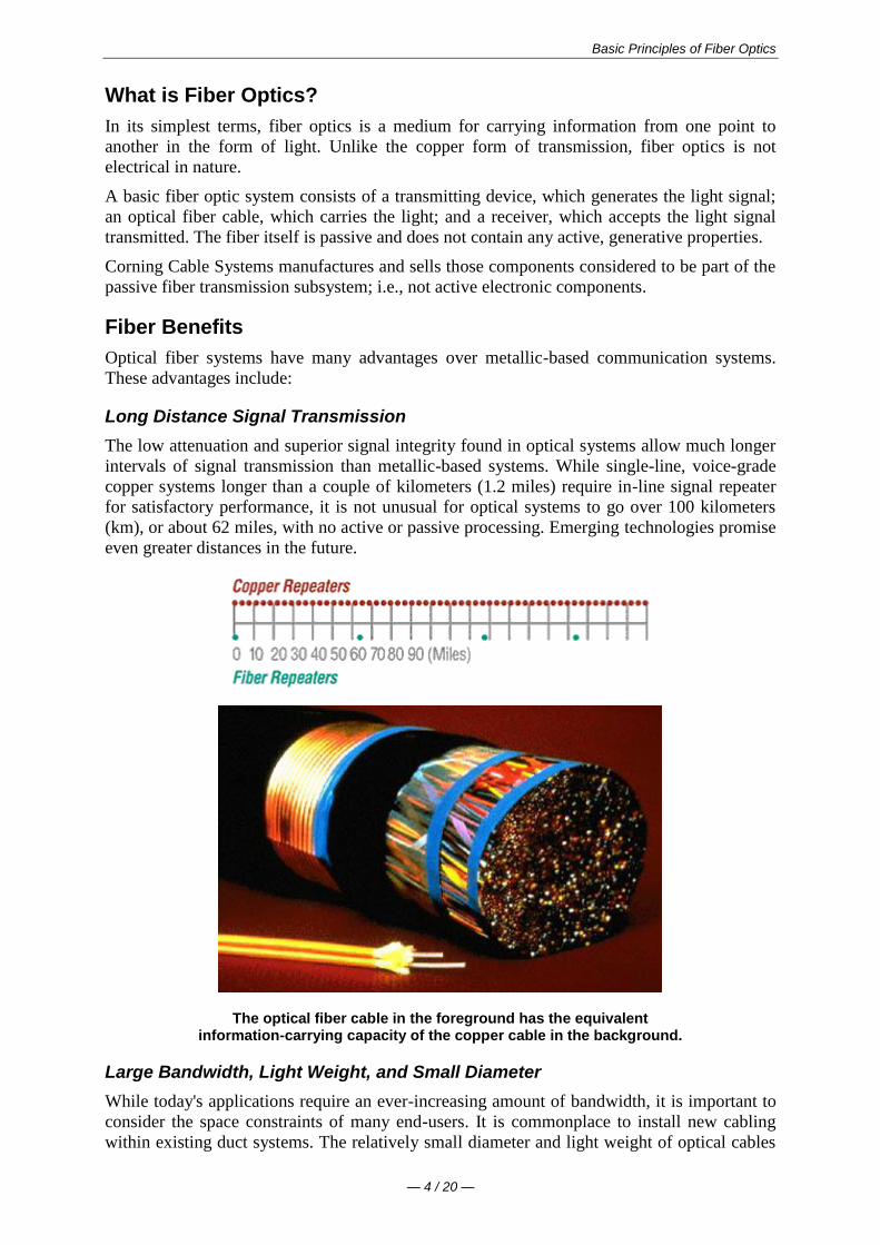
Basic Principles of Fiber Optics
mdash 4 20 mdash
What is Fiber Optics
In its simplest terms fiber optics is a medium for carrying information from one point to
another in the form of light Unlike the copper form of transmission fiber optics is not
electrical in nature
A basic fiber optic system consists of a transmitting device which generates the light signal
an optical fiber cable which carries the light and a receiver which accepts the light signal
transmitted The fiber itself is passive and does not contain any active generative properties
Corning Cable Systems manufactures and sells those components considered to be part of the
passive fiber transmission subsystem ie not active electronic components
Fiber Benefits
Optical fiber systems have many advantages over metallic-based communication systems
These advantages include
Long Distance Signal Transmission
The low attenuation and superior signal integrity found in optical systems allow much longer
intervals of signal transmission than metallic-based systems While single-line voice-grade
copper systems longer than a couple of kilometers (12 miles) require in-line signal repeater
for satisfactory performance it is not unusual for optical systems to go over 100 kilometers
(km) or about 62 miles with no active or passive processing Emerging technologies promise
even greater distances in the future
The optical fiber cable in the foreground has the equivalent information-carrying capacity of the copper cable in the background
Large Bandwidth Light Weight and Small Diameter
While todays applications require an ever-increasing amount of bandwidth it is important to
consider the space constraints of many end-users It is commonplace to install new cabling
within existing duct systems The relatively small diameter and light weight of optical cables
Basic Principles of Fiber Optics
mdash 5 20 mdash
makes such installations easy and practical and saves valuable conduit space in these
environments
Long Lengths
Long continuous lengths also provide advantages for installers and end-users Small
diameters make it practical to manufacture and install much longer lengths than for metallic
cables twelve-kilometer (12 km) continuous optical cable lengths are common Corning
Cable Systems manufactures continuous single-mode cable lengths up to 12 km with a 96-
inch reel size being the primary limiting factor
Multimode cable lengths can be 4 km or more although most standards require a maximum
length of 2 km or less Multimode cable lengths are based on industry demand (Single-mode
and multimode fibers will be covered in detail later in this text)
Easy Installation and Upgrades
Long lengths make optical cable installation much easier and less expensive Optical fiber
cables can be installed with the same equipment that is used to install copper and coaxial
cables with some modifications due to the small size and limited pull tension and bend radius
of optical cables
Optical cables can typically be installed in duct systems in spans of 6000 meters or more
depending on the ducts condition layout of the duct system and installation technique The
longer cables can be coiled at an intermediate point and pulled farther into the duct system as
necessary
System designers typically plan optical systems that will meet growth needs for a 15- to 20-
year span Although sometimes difficult to predict growth can be accommodated by
installing spare fibers for future requirements Installation of spare fibers today is more
economical than installing additional cables later
The dielectric nature of optical fiber can eliminate the dangers found in areas of high lightning-strike incidence
Non-Conductivity
Another advantage of optical fibers is their dielectric nature Since optical fiber has no
metallic components it can be installed in areas with electromagnetic interference (EMI)
including radio frequency interference (RFI) Areas with high EMI include utility lines
power-carrying lines and railroad tracks All-dielectric cables are also ideal for areas of high
lightning-strike incidence
Basic Principles of Fiber Optics
mdash 6 20 mdash
Security
Unlike metallic-based systems the dielectric nature of optical fiber makes it impossible to
remotely detect the signal being transmitted within the cable The only way to do so is by
actually accessing the optical fiber itself Accessing the fiber requires intervention that is
easily detectable by security surveillance These circumstances make fiber extremely
attractive to governmental bodies banks and others with major security concerns
Designed for Future Applications Needs
Fiber optics is affordable today as electronics prices fall and optical cable pricing remains
low In many cases fiber solutions are less costly than copper
As bandwidth demands increase rapidly with technological advances fiber will continue to
play a vital role in the long-term success of telecommunications
Key Points in Fiber History
Most people remember Paul Reveres one if by land and two if by sea from early American
history He used lanterns to communicate information Although not sophisticated this was
an early example of optical communication
In 1870 British physicist John Tyndal gave us another example Tyndal set up a tank of water
with a pipe that ran out one side He allowed the water to flow from the pipe and then shone a
bright light from inside the tank into the water stream As the water fell an arc of light
followed the water down This demonstrated total internal reflection a principle that will be
discussed in more detail later
In 1880 Alexander Graham Bell invented the photophone Bell considered this a greater
discovery than his previous invention the telephone With the photophone Bell would speak
into a microphone which would cause a mirror to vibrate The suns light would strike the
mirror and the vibration of the mirror would transmit the light across an open distance of
about 200 meters (656 feet) The receivers mirror would receive the light and cause a
selenium crystal to vibrate and the noise would come out on the other end (See Figure 1
below) Although the photophone was successful in allowing conversation over open space it
had a few drawbacks it did not work well at night in the rain or if someone walked between
the signal and the receiver Eventually Bell gave up on this idea
Figure 1
Basic Principles of Fiber Optics
mdash 7 20 mdash
It wasnt until the late 1950s that the laser was invented This device was a finely-controlled
beam of light that could transmit information over long distances Unfortunately the same
drawbacks experienced by Alexander Graham Bell also plagued the laser Although it could
be used at night it didnt work during rain fog or any time a building was erected between
the sender and the receiver
Dr Robert Maurer Peter Schultz and Donald Keck of Corning Incorporated in Corning New
York came up with the first low loss optical fiber with less than 20 dBkm (decibels per
kilometer) loss (Today single-mode premium grade fiber is sold with specifications of 025
dBkm or better)
In 1977 Corning joined forces with another technological giant Siemens Corporation to
form Corning Cable Systems Cornings extensive work with fiber coupled with Siemens
cabling technology helped launch a new era in optical fiber cable and associated products
Today Corning Cable Systems is a world leader in the manufacture of fiber optic cabling
system products for voice data and video communications applications
Check Your Understanding
Would you like to see how much youve learned
1 In what decade did optical fiber communications become commercially viable
1870
1950
1970
1980
2 Which of the following is a good example of an optical fiber application for
telecommunications
Local or long-distance telephone communications
Medical instruments for orthoscopic surgery
Missile guidance and target tracking
3 Which of the following is not true about optical fiber transmission systems
Can be used for voice or data and video
Are almost always more expensive than copper
Easy to install and upgrade
Are virtually immune to electromagnetic and radio-frequency interference
Bibliography
Introduction to Basic Fiber Optics
Session Outline Corning Cable Systems 1994
Just the Facts
Corning Incorporated Corning New York 1993
Jeff Englebert et alOptical Fiber and Cable for Telecommunications
Corning Cable Systems 1996
TR-07-S Hands-On Fiber Optic Installation for Local Area Networks
Corning Cable Systems Hickory North Carolina 1989
Jeff Hecht Understanding Fiber Optics
Howard W Sams amp Company Carmel Indiana 1987
Basic Principles of Fiber Optics
mdash 8 20 mdash
Basic Principles of Operation
Figure 2
The Information Transmision Sequence
As depicted above information (voice data or video) is encoded into electrical signals At
the light source these electrical signals are converted into light signals
It is important to note that fiber has the capability to carry either analog or digital signals
Many people believe that fiber can transmit only digital signals due to the onoff binary
characteristic of the light source The intensity of the light and the frequency at which the
intensity changes can be used for AM and FM analog transmission
Once the signals are converted to light they travel down the fiber until they reach a detector
which changes the light signals back into electrical signals This area from light source to
detector constitutes the passive transmission subsystem ie that part of the system
manufactured and sold by Corning Cable Systems
Finally the electrical signals are decoded into information in the form of voice data or video
Cross Section of a Typical Fiber
Figure 3
Basic Principles of Fiber Optics
mdash 9 20 mdash
Optical fiber for telecommunications consists of three components core cladding amp coating
The core is the central region of an optical fiber through which light is transmitted In general
the telecommunications industry uses sizes from 83 micrometer (microm) to 625 micrometers
The standard telecommunications core sizes in use today are 83 microm (single-mode) 50 microm
(multimode) and 625 microm (multimode) (Single-mode and multimode will be discussed
shortly) The diameter of the cladding surrounding each of these cores is 125 microm Core sizes
of 85 microm and 100 microm have been used in early applications but are not typically used today
To put these sizes into perspective compare them to a human hair which is approximately 70
microm or 0003 inch
The core and cladding are manufactured together as a single piece of silica glass with slightly
different compositions and cannot be separated from one another The glass does not have a
hole in the core but is completely solid throughout
The third section of an optical fiber is the outer protective coating This coating is typically an
ultraviolet (UV) light-cured acrylate applied during the manufacturing process to provide
physical and environmental protection for the fiber During the installation process this
coating is stripped away from the cladding to allow proper termination to an optical
transmission system
The coating size can vary but the standard sizes are 250 microm or 900 microm The 250 microm coating
takes less space in larger outdoor cables The 900 microm coating is larger and more suitable for
smaller indoor cables
Types of Fiber
Once light enters an optical fiber it travels in a stable state called a mode There can be from
one to hundreds of modes depending on the type of fiber Each mode carries a portion of the
light from the input signal
Generally speaking the number of modes in a fiber is a function of the relationship between
core diameter numerical aperture and wavelength which will be discussed later in the text
Figure 4
Every telecommunications fiber falls into one of two categories single-mode or multimode
It is impossible to distinguish between single-mode and multimode fiber with the naked eye
There is no difference in outward appearance only in core size Both fiber types act as a
transmission medium for light but they operate in different ways have different
characteristics and serve different applications
Single-Mode (SM) fiber allows for only one pathway or mode of light to travel within the
fiber The core size is typically 83 microm Single-mode fibers are used in applications where low
signal loss and high data rates are required such as on long spans where repeateramplifier
spacing needs to be maximized
Basic Principles of Fiber Optics
mdash 10 20 mdash
Multimode (MM) fiber allows more than one mode of light Common MM core sizes are 50
microm and 625 microm Multimode fiber is better suited for shorter distance applications Where
costly electronics are heavily concentrated the primary cost of the system does not lie with
the cable In such a case MM fiber is more economical because it can be used with
inexpensive connectors and LED transmitters making the total system cost lower This makes
MM fiber the ideal choice for short distance lower bandwidth applications
Check Your Understanding
Would you like to see how much youve learned
1 What purpose does the core of an optical fiber serve
It protects the fiber from the environment
It carries light through the fiber
It separates the cladding and the coating
2 Which of the following is NOT true of single-mode fiber
It carries more information than multimode fiber
Its core is smaller than multimode fiber
It is hollow in the center
3 At installation which of the following is NOT true about optical fiber
The cladding and coating are stripped away
The fiber has the ability to carry either analog or digital signals
Light signals must enter the fiber within the acceptance cone to propagate
Applied Principles of Operation
Index of Refraction (IOR)
The index of refraction (IOR) is a way of measuring the speed of light in a material Light
travels fastest in a vacuum such as outer space The actual speed of light in a vacuum is
300000 kilometers per second or 186000 miles per second
Index of Refraction is calculated by dividing the speed of light in a vacuum by the speed of
light in some other medium
The Index of Refraction of a vacuum by definition has a value of 1
For the sake of simplicity typical values are provided here in Figure 5 Notice that the typical
value for the cladding of an optical fiber is 146 The core value is 148 The larger the index
of refraction the more slowly light travels in that medium
Figure 5
Basic Principles of Fiber Optics
mdash 11 20 mdash
Total Internal Refraction
When a light ray traveling in one material hits a different material and reflects back into the
original material without any loss of light total internal refraction occurs
Since the core and cladding are constructed from different compositions of glass
theoretically light entering the core is confined to the boundaries of the core because it
reflects back whenever it hits the cladding For total internal reflection to occur the index of
refraction of the core must be higher than that of the cladding
Acceptance Cone
As mentioned earlier electrical signals are converted to light signals before they enter an
optical fiber To ensure that the signals reflect and travel correctly through the core the light
must enter the core through an imaginary acceptance cone (See Figure 7 below) The size of
this acceptance cone is a function of the refractive index difference between the core and the
cladding
In simpler terms there is a maximum angle from the fiber axis at which light may enter the
fiber so that it will propagate or travel in the core of the fiber The sine of this maximum
angle is the numerical aperture (NA) of the fiber Fiber with a larger NA requires less
precision to splice and work with than fiber with a smaller NA Single-mode fiber has a small
NA
Check Your Understanding
Would you like to see how much youve learned
1 Which of the following is true of the index of refraction
It is a way of measuring the speed of light in a material
It is calculated by dividing the speed of light in some medium by the speed of light
in a vacuum
When calculated it shows that the fastest light speed occurs in air
2 Total internal reflection is
Reflection that occurs when a light ray traveling in one material hits another
material and reflects back into the original material without any loss of light
Basic Principles of Fiber Optics
mdash 12 20 mdash
Complete meditation without interruption
Reflection that occurs when the refractive index of the core is lower than the
cladding
Optical Fiber Parameters
As with any type of transmission system there are certain parameters that affect the systems
operation
Wavelength
Light that can be seen by the unaided human eye is said to be in the visible spectrum In the
visible spectrum wavelength can be described as the color of light
To put this into perspective take a look at Figure 8 Notice that the colors of the rainbow -
red orange yellow green blue (indigo not shown) and violet fall within the visible
spectrum
Figure 8
Basic Principles of Fiber Optics
mdash 13 20 mdash
Optical fiber transmission uses wavelengths which are above the visible light spectrum and
thus undetectable to the unaided eye Typical optical transmission wavelengths are 850
nanometers (nm) 1310 nm and 1550 nm
Both lasers and LEDs (light-emitting diodes) are used to transmit light through optical fiber
Lasers are usually used for 1310 or 1550 nanometer single-mode applications LEDs are
used for 850 or 1300 nanometer multimode applications
Safety note Never look into the end of a fiber which may have a laser coupled to it Laser
light is invisible and can damage the eyes Viewing it directly does not cause pain The iris of
the eye will not close involuntarily as when viewing a bright light consequently serious
damage to the retina of the eye is possible Should accidental exposure to laser light be
suspected an eye examination should be arranged immediately
Window
There are ranges of wavelengths at which the fiber operates best Each range is known as an
operating window Each window is centered around the typical operational wavelength
Figure 9
These wavelengths were chosen because they best match the transmission properties of
available light sources with the transmission qualities of optical fiber
Frequency
The frequency of a system is the speed of modulation of the digital or analog output of the
light source in other words the number of pulses per second emitted from the light source
Frequency is measured in units of hertz (Hz) where 1 hertz is equal to 1 pulse or cycle per
second (Figure 10) A more practical measurement for optical communications is megahertz
(MHz) or millions of pulses per second
Figure 10
Attenuation
Attenuation is the loss of optical power as light travels down a fiber It is measured in decibels
(dBkm) Over a set distance a fiber with a lower attenuation will allow more power to reach
its receiver than a fiber with higher attenuation
Basic Principles of Fiber Optics
mdash 14 20 mdash
While low-loss optical systems are always desirable it is possible to lose a large portion of
the initial signal power without significant problems A loss of 50 of initial power is equal
to a 30 dB loss Any time fibers are joined together there will be some loss Losses for fusion
splicing and for mechanical splicing are typically 02 dB or less
Attenuation can be caused by several factors but is generally placed in one of two categories
intrinsic or extrinsic
Intrinsic Attenuation
Intrinsic attenuation occurs due to something inside or inherent to the fiber It is caused by
impurities in the glass during the manufacturing process As precise as manufacturing is there
is no way to eliminate all impurities though technological advances have caused attenuation
to decrease dramatically since the first optical fiber in 1970
When a light signal hits an impurity in the fiber one of two things will occur it will scatter or
it will be absorbed
Scattering
Rayleigh scattering accounts for the majority (about 96) of attenuation in optical fiber
Light travels in the core and interacts with the atoms in the glass The light waves elastically
collide with the atoms and light is scattered as a result
Rayleigh scattering is the result of these elastic collisions between the light wave and the
atoms in the fiber If the scattered light maintains an angle that supports forward travel within
the core no attenuation occurs If the light is scattered at an angle that does not support
continued forward travel the light is diverted out of the core and attenuation occurs
Figure 11
Some scattered light is reflected back toward the light source (input end) This is a property
that is used in an Optical Time Domain Reflectometer (OTDR) to test fibers This same
principle applies to analyzing loss associated with localized events in the fiber such as
splices
Absorption
The second type of intrinsic attenuation in fiber is absorption Absorption accounts for 3-5
of fiber attenuation This phenomenon causes a light signal to be absorbed by natural
impurities in the glass and converted to vibrational energy or some other form of energy
(Figure 12)
Unlike scattering absorption can be limited by controlling the amount of impurities during
the manufacturing process
Basic Principles of Fiber Optics
mdash 15 20 mdash
Figure 12
Extrinsic Attenuation
The second category of attenuation is extrinsic attenuation Extrinsic attenuation can be
caused by two external mechanisms macrobending or microbending Both cause a reduction
of optical power
Macrobending
If a bend is imposed on an optical fiber strain is placed on the fiber along the region that is
bent The bending strain will affect the refractive index and the critical angle of the light ray
in that specific area As a result light traveling in the core can refract out and loss occurs
(Figure 13)
A macrobend is a large-scale bend that is visible for example a fiber wrapped around a
persons finger This loss is generally reversible once bends are corrected
To prevent macrobends all optical fiber (and optical fiber cable) has a minimum bend radius
specification that should not be exceeded This is a restriction on how much bend a fiber can
withstand before experiencing problems in optical performance or mechanical reliability The
rule of thumb for minimum bend radius is 1 12 for bare single-mode fiber 10 times the
cables outside diameter (OD) for non-armored cable and 15 times the cables OD for
armored cable
Figure 13
Microbending
The second extrinsic cause of attenuation is a microbend This is a small-scale distortion
generally indicative of pressure on the fiber (See Figure 14 below) Microbending may be
related to temperature tensile stress or crushing force Like macrobending microbending
will cause a reduction of optical power in the glass
Microbending is very localized and the bend may not be clearly visible upon inspection With
bare fiber microbending may be reversible in the cabling process it may not
Basic Principles of Fiber Optics
mdash 16 20 mdash
Figure 14
Dispersion
Dispersion is the spreading of a light pulse as it travels down a fiber (See Figure 15) As
the pulses spread or broaden they tend to overlap and are no longer distinguishable by the
receiver as 0s and 1s Light pulses launched close together (high data rates) that spread too
much (high dispersion) result in errors and loss of information
Chromatic dispersion occurs as a result of the range of wavelengths in the light source Light
from lasers and LEDs consists of a range of wavelengths Each of these wavelengths travels at
a slightly different speed Over distance the varying wavelength speeds cause the light pulse
to spread in time This is of most importance in single-mode applications
Modal dispersion is significant in multimode applications where the various modes of light
traveling down the fiber arrive at the receiver at different times causing a spreading effect
Figure 15
Pulse width is measured at full width-half maximum in other words the full width of the
pulse at half the maximum pulse height Dispersion limits how fast or how much
information can be sent over an optical fiber
There are other effects of dispersion but further discussion is beyond the scope of this text
For more in-depth reading please consult the bibliography at the end of this publication
Bandwidth
In simplest terms bandwidth is the amount of information a fiber can carry so that every pulse
is distinguishable by the receiver at the end (Figure 16)
Basic Principles of Fiber Optics
mdash 17 20 mdash
Figure 16
As discussed in the previous section dispersion causes light pulses to spread The spreading
of these light pulses causes them to merge together At a certain distance and frequency the
pulses become unreadable by the receiver The multiple pathways of a multimode fiber cause
this overlap to be much greater than for single-mode fiber These different paths have
different lengths which cause each mode of light to arrive at a different time
System bandwidth is measured in megahertz (MHz) at one km In general when a systems
bandwidth is 200 MHzmiddotkm it means that 200 million pulses of light per second will travel
down 1 km (1000 meters) of fiber and each pulse will be distinguishable by the receiver
Check Your Understanding
Would you like to see how much youve learned
1 In optical fiber systems what are the typical wavelengths of operation
400 nm 455 nm 490 nm
620 nm 750 nm 800 nm
850 nm 1310 nm 1550 nm
2 What is an optical window
A glass object on the side of a building
A range of wavelengths at which fiber best operates
The moment in time when fiber became a commercially-viable enterprise
3 Which of the following is not true of attenuation
It is the loss of optical power as light travels down a fiber
It may be induced by scattering absorbing macrobending and microbending
It is measured in nanometers
4 What is bandwidth
A measure of the information-carrying capacity of an optical fiber
The side-to-side measurement of a wedding ring
A term used to express the total loss of an optical system
Fiber Manufacturing
There are several ways to manufacture optical fiber but this text will concentrate on the
method developed patented and used by the former Corning Glass Works now Corning
Incorporated
This method called Outside Vapor Deposition or OVD has three steps or phases laydown
consolidation and draw
Basic Principles of Fiber Optics
mdash 18 20 mdash
Laydown
In the laydown step a soot preform is made from ultrapure vapors of silicon tetrachloride and
germanium tetrachloride The vapors travel through a traversing burner and react in the flame
to form soot particles of silica and germania
Figure 17
The OVD process is distinguished by the method of depositing the soot These particles are
deposited on the surface of a rotating target rod The core material is deposited first followed
by the pure silica cladding Since both core and cladding raw materials are vapor-deposited
the entire preform is extremely pure
Consolidation
When deposition is complete the target rod is removed from the center of the porous preform
and the preform is placed into a consolidation furnace During the consolidation process the
water vapor is removed from the preform This high-temperature consolidation step sinters the
preform into a solid dense transparent glass blank The hole left by the target rod is fused
solid by the extremely high temperature of the draw furnace
Draw
The finished glass preform is placed in a draw tower and drawn into a continuous strand of
glass fiber First the blank is lowered into the top of the draw furnace
Basic Principles of Fiber Optics
mdash 19 20 mdash
Figure 18
The tip of the blank is heated until a piece of molten glass called a gob begins to fall from
the blank like hot taffy It pulls a thin strand of glass the beginning of an optical fiber
The fiber goes through a precise on-line diameter monitor to ensure specified outside
diameter Next coatings are applied and cured using ultraviolet lamps
At the bottom of the draw the fiber is wound on spools Each fiber is assigned a unique
identification number that encodes all relevant manufacturing data including raw materials
and manufacturing equipment
Note Extensive text and graphics in this Fiber Manufacturing section are used with
permission of Corning Communications
Check Your Understanding
Would you like to see how much youve learned
1 What are the three steps of fiber manufacture using the Outside Vapor Deposition (OVD)
method
Burner vapor fuel
Laydown consolidation draw
Gas glass spool
2 Which of the following is NOT true about the laydown stage of OVD fiber manufacture
A rotating target rod collects soot deposited from the burner
Basic Principles of Fiber Optics
mdash 20 20 mdash
The soot forms a preform
The preform is highly impure until it reaches the consolidation phase
3 Which of the following is NOT true about the consolidation stage of fiber manufacture
The removal of the target rod causes the core of the fiber to be hollow
Water vapor is removed from the preform
The white preform becomes a solid dense transparent glass blank
4 Which of the following is NOT true about the draw stage of fiber manufacture
The glass preform is drawn into a continuous piece of glass fiber
Fiber diameters are measured on-line
Coatings are applied and cured using infrared lamps
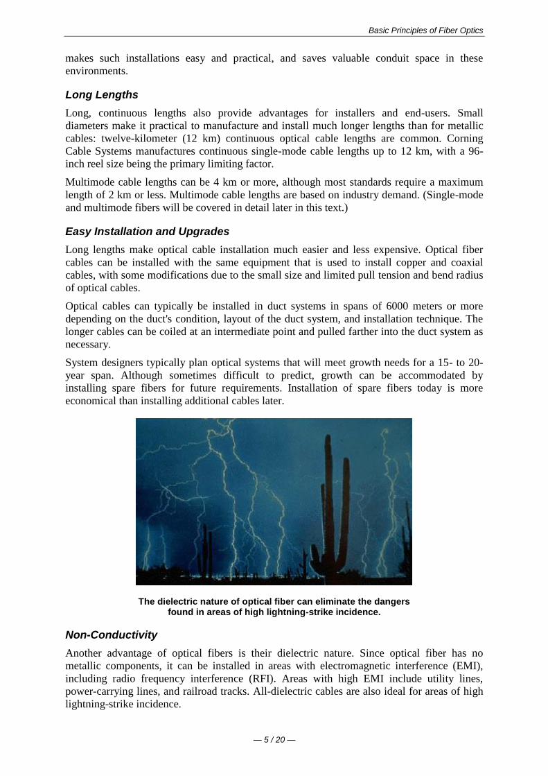
Basic Principles of Fiber Optics
mdash 5 20 mdash
makes such installations easy and practical and saves valuable conduit space in these
environments
Long Lengths
Long continuous lengths also provide advantages for installers and end-users Small
diameters make it practical to manufacture and install much longer lengths than for metallic
cables twelve-kilometer (12 km) continuous optical cable lengths are common Corning
Cable Systems manufactures continuous single-mode cable lengths up to 12 km with a 96-
inch reel size being the primary limiting factor
Multimode cable lengths can be 4 km or more although most standards require a maximum
length of 2 km or less Multimode cable lengths are based on industry demand (Single-mode
and multimode fibers will be covered in detail later in this text)
Easy Installation and Upgrades
Long lengths make optical cable installation much easier and less expensive Optical fiber
cables can be installed with the same equipment that is used to install copper and coaxial
cables with some modifications due to the small size and limited pull tension and bend radius
of optical cables
Optical cables can typically be installed in duct systems in spans of 6000 meters or more
depending on the ducts condition layout of the duct system and installation technique The
longer cables can be coiled at an intermediate point and pulled farther into the duct system as
necessary
System designers typically plan optical systems that will meet growth needs for a 15- to 20-
year span Although sometimes difficult to predict growth can be accommodated by
installing spare fibers for future requirements Installation of spare fibers today is more
economical than installing additional cables later
The dielectric nature of optical fiber can eliminate the dangers found in areas of high lightning-strike incidence
Non-Conductivity
Another advantage of optical fibers is their dielectric nature Since optical fiber has no
metallic components it can be installed in areas with electromagnetic interference (EMI)
including radio frequency interference (RFI) Areas with high EMI include utility lines
power-carrying lines and railroad tracks All-dielectric cables are also ideal for areas of high
lightning-strike incidence
Basic Principles of Fiber Optics
mdash 6 20 mdash
Security
Unlike metallic-based systems the dielectric nature of optical fiber makes it impossible to
remotely detect the signal being transmitted within the cable The only way to do so is by
actually accessing the optical fiber itself Accessing the fiber requires intervention that is
easily detectable by security surveillance These circumstances make fiber extremely
attractive to governmental bodies banks and others with major security concerns
Designed for Future Applications Needs
Fiber optics is affordable today as electronics prices fall and optical cable pricing remains
low In many cases fiber solutions are less costly than copper
As bandwidth demands increase rapidly with technological advances fiber will continue to
play a vital role in the long-term success of telecommunications
Key Points in Fiber History
Most people remember Paul Reveres one if by land and two if by sea from early American
history He used lanterns to communicate information Although not sophisticated this was
an early example of optical communication
In 1870 British physicist John Tyndal gave us another example Tyndal set up a tank of water
with a pipe that ran out one side He allowed the water to flow from the pipe and then shone a
bright light from inside the tank into the water stream As the water fell an arc of light
followed the water down This demonstrated total internal reflection a principle that will be
discussed in more detail later
In 1880 Alexander Graham Bell invented the photophone Bell considered this a greater
discovery than his previous invention the telephone With the photophone Bell would speak
into a microphone which would cause a mirror to vibrate The suns light would strike the
mirror and the vibration of the mirror would transmit the light across an open distance of
about 200 meters (656 feet) The receivers mirror would receive the light and cause a
selenium crystal to vibrate and the noise would come out on the other end (See Figure 1
below) Although the photophone was successful in allowing conversation over open space it
had a few drawbacks it did not work well at night in the rain or if someone walked between
the signal and the receiver Eventually Bell gave up on this idea
Figure 1
Basic Principles of Fiber Optics
mdash 7 20 mdash
It wasnt until the late 1950s that the laser was invented This device was a finely-controlled
beam of light that could transmit information over long distances Unfortunately the same
drawbacks experienced by Alexander Graham Bell also plagued the laser Although it could
be used at night it didnt work during rain fog or any time a building was erected between
the sender and the receiver
Dr Robert Maurer Peter Schultz and Donald Keck of Corning Incorporated in Corning New
York came up with the first low loss optical fiber with less than 20 dBkm (decibels per
kilometer) loss (Today single-mode premium grade fiber is sold with specifications of 025
dBkm or better)
In 1977 Corning joined forces with another technological giant Siemens Corporation to
form Corning Cable Systems Cornings extensive work with fiber coupled with Siemens
cabling technology helped launch a new era in optical fiber cable and associated products
Today Corning Cable Systems is a world leader in the manufacture of fiber optic cabling
system products for voice data and video communications applications
Check Your Understanding
Would you like to see how much youve learned
1 In what decade did optical fiber communications become commercially viable
1870
1950
1970
1980
2 Which of the following is a good example of an optical fiber application for
telecommunications
Local or long-distance telephone communications
Medical instruments for orthoscopic surgery
Missile guidance and target tracking
3 Which of the following is not true about optical fiber transmission systems
Can be used for voice or data and video
Are almost always more expensive than copper
Easy to install and upgrade
Are virtually immune to electromagnetic and radio-frequency interference
Bibliography
Introduction to Basic Fiber Optics
Session Outline Corning Cable Systems 1994
Just the Facts
Corning Incorporated Corning New York 1993
Jeff Englebert et alOptical Fiber and Cable for Telecommunications
Corning Cable Systems 1996
TR-07-S Hands-On Fiber Optic Installation for Local Area Networks
Corning Cable Systems Hickory North Carolina 1989
Jeff Hecht Understanding Fiber Optics
Howard W Sams amp Company Carmel Indiana 1987
Basic Principles of Fiber Optics
mdash 8 20 mdash
Basic Principles of Operation
Figure 2
The Information Transmision Sequence
As depicted above information (voice data or video) is encoded into electrical signals At
the light source these electrical signals are converted into light signals
It is important to note that fiber has the capability to carry either analog or digital signals
Many people believe that fiber can transmit only digital signals due to the onoff binary
characteristic of the light source The intensity of the light and the frequency at which the
intensity changes can be used for AM and FM analog transmission
Once the signals are converted to light they travel down the fiber until they reach a detector
which changes the light signals back into electrical signals This area from light source to
detector constitutes the passive transmission subsystem ie that part of the system
manufactured and sold by Corning Cable Systems
Finally the electrical signals are decoded into information in the form of voice data or video
Cross Section of a Typical Fiber
Figure 3
Basic Principles of Fiber Optics
mdash 9 20 mdash
Optical fiber for telecommunications consists of three components core cladding amp coating
The core is the central region of an optical fiber through which light is transmitted In general
the telecommunications industry uses sizes from 83 micrometer (microm) to 625 micrometers
The standard telecommunications core sizes in use today are 83 microm (single-mode) 50 microm
(multimode) and 625 microm (multimode) (Single-mode and multimode will be discussed
shortly) The diameter of the cladding surrounding each of these cores is 125 microm Core sizes
of 85 microm and 100 microm have been used in early applications but are not typically used today
To put these sizes into perspective compare them to a human hair which is approximately 70
microm or 0003 inch
The core and cladding are manufactured together as a single piece of silica glass with slightly
different compositions and cannot be separated from one another The glass does not have a
hole in the core but is completely solid throughout
The third section of an optical fiber is the outer protective coating This coating is typically an
ultraviolet (UV) light-cured acrylate applied during the manufacturing process to provide
physical and environmental protection for the fiber During the installation process this
coating is stripped away from the cladding to allow proper termination to an optical
transmission system
The coating size can vary but the standard sizes are 250 microm or 900 microm The 250 microm coating
takes less space in larger outdoor cables The 900 microm coating is larger and more suitable for
smaller indoor cables
Types of Fiber
Once light enters an optical fiber it travels in a stable state called a mode There can be from
one to hundreds of modes depending on the type of fiber Each mode carries a portion of the
light from the input signal
Generally speaking the number of modes in a fiber is a function of the relationship between
core diameter numerical aperture and wavelength which will be discussed later in the text
Figure 4
Every telecommunications fiber falls into one of two categories single-mode or multimode
It is impossible to distinguish between single-mode and multimode fiber with the naked eye
There is no difference in outward appearance only in core size Both fiber types act as a
transmission medium for light but they operate in different ways have different
characteristics and serve different applications
Single-Mode (SM) fiber allows for only one pathway or mode of light to travel within the
fiber The core size is typically 83 microm Single-mode fibers are used in applications where low
signal loss and high data rates are required such as on long spans where repeateramplifier
spacing needs to be maximized
Basic Principles of Fiber Optics
mdash 10 20 mdash
Multimode (MM) fiber allows more than one mode of light Common MM core sizes are 50
microm and 625 microm Multimode fiber is better suited for shorter distance applications Where
costly electronics are heavily concentrated the primary cost of the system does not lie with
the cable In such a case MM fiber is more economical because it can be used with
inexpensive connectors and LED transmitters making the total system cost lower This makes
MM fiber the ideal choice for short distance lower bandwidth applications
Check Your Understanding
Would you like to see how much youve learned
1 What purpose does the core of an optical fiber serve
It protects the fiber from the environment
It carries light through the fiber
It separates the cladding and the coating
2 Which of the following is NOT true of single-mode fiber
It carries more information than multimode fiber
Its core is smaller than multimode fiber
It is hollow in the center
3 At installation which of the following is NOT true about optical fiber
The cladding and coating are stripped away
The fiber has the ability to carry either analog or digital signals
Light signals must enter the fiber within the acceptance cone to propagate
Applied Principles of Operation
Index of Refraction (IOR)
The index of refraction (IOR) is a way of measuring the speed of light in a material Light
travels fastest in a vacuum such as outer space The actual speed of light in a vacuum is
300000 kilometers per second or 186000 miles per second
Index of Refraction is calculated by dividing the speed of light in a vacuum by the speed of
light in some other medium
The Index of Refraction of a vacuum by definition has a value of 1
For the sake of simplicity typical values are provided here in Figure 5 Notice that the typical
value for the cladding of an optical fiber is 146 The core value is 148 The larger the index
of refraction the more slowly light travels in that medium
Figure 5
Basic Principles of Fiber Optics
mdash 11 20 mdash
Total Internal Refraction
When a light ray traveling in one material hits a different material and reflects back into the
original material without any loss of light total internal refraction occurs
Since the core and cladding are constructed from different compositions of glass
theoretically light entering the core is confined to the boundaries of the core because it
reflects back whenever it hits the cladding For total internal reflection to occur the index of
refraction of the core must be higher than that of the cladding
Acceptance Cone
As mentioned earlier electrical signals are converted to light signals before they enter an
optical fiber To ensure that the signals reflect and travel correctly through the core the light
must enter the core through an imaginary acceptance cone (See Figure 7 below) The size of
this acceptance cone is a function of the refractive index difference between the core and the
cladding
In simpler terms there is a maximum angle from the fiber axis at which light may enter the
fiber so that it will propagate or travel in the core of the fiber The sine of this maximum
angle is the numerical aperture (NA) of the fiber Fiber with a larger NA requires less
precision to splice and work with than fiber with a smaller NA Single-mode fiber has a small
NA
Check Your Understanding
Would you like to see how much youve learned
1 Which of the following is true of the index of refraction
It is a way of measuring the speed of light in a material
It is calculated by dividing the speed of light in some medium by the speed of light
in a vacuum
When calculated it shows that the fastest light speed occurs in air
2 Total internal reflection is
Reflection that occurs when a light ray traveling in one material hits another
material and reflects back into the original material without any loss of light
Basic Principles of Fiber Optics
mdash 12 20 mdash
Complete meditation without interruption
Reflection that occurs when the refractive index of the core is lower than the
cladding
Optical Fiber Parameters
As with any type of transmission system there are certain parameters that affect the systems
operation
Wavelength
Light that can be seen by the unaided human eye is said to be in the visible spectrum In the
visible spectrum wavelength can be described as the color of light
To put this into perspective take a look at Figure 8 Notice that the colors of the rainbow -
red orange yellow green blue (indigo not shown) and violet fall within the visible
spectrum
Figure 8
Basic Principles of Fiber Optics
mdash 13 20 mdash
Optical fiber transmission uses wavelengths which are above the visible light spectrum and
thus undetectable to the unaided eye Typical optical transmission wavelengths are 850
nanometers (nm) 1310 nm and 1550 nm
Both lasers and LEDs (light-emitting diodes) are used to transmit light through optical fiber
Lasers are usually used for 1310 or 1550 nanometer single-mode applications LEDs are
used for 850 or 1300 nanometer multimode applications
Safety note Never look into the end of a fiber which may have a laser coupled to it Laser
light is invisible and can damage the eyes Viewing it directly does not cause pain The iris of
the eye will not close involuntarily as when viewing a bright light consequently serious
damage to the retina of the eye is possible Should accidental exposure to laser light be
suspected an eye examination should be arranged immediately
Window
There are ranges of wavelengths at which the fiber operates best Each range is known as an
operating window Each window is centered around the typical operational wavelength
Figure 9
These wavelengths were chosen because they best match the transmission properties of
available light sources with the transmission qualities of optical fiber
Frequency
The frequency of a system is the speed of modulation of the digital or analog output of the
light source in other words the number of pulses per second emitted from the light source
Frequency is measured in units of hertz (Hz) where 1 hertz is equal to 1 pulse or cycle per
second (Figure 10) A more practical measurement for optical communications is megahertz
(MHz) or millions of pulses per second
Figure 10
Attenuation
Attenuation is the loss of optical power as light travels down a fiber It is measured in decibels
(dBkm) Over a set distance a fiber with a lower attenuation will allow more power to reach
its receiver than a fiber with higher attenuation
Basic Principles of Fiber Optics
mdash 14 20 mdash
While low-loss optical systems are always desirable it is possible to lose a large portion of
the initial signal power without significant problems A loss of 50 of initial power is equal
to a 30 dB loss Any time fibers are joined together there will be some loss Losses for fusion
splicing and for mechanical splicing are typically 02 dB or less
Attenuation can be caused by several factors but is generally placed in one of two categories
intrinsic or extrinsic
Intrinsic Attenuation
Intrinsic attenuation occurs due to something inside or inherent to the fiber It is caused by
impurities in the glass during the manufacturing process As precise as manufacturing is there
is no way to eliminate all impurities though technological advances have caused attenuation
to decrease dramatically since the first optical fiber in 1970
When a light signal hits an impurity in the fiber one of two things will occur it will scatter or
it will be absorbed
Scattering
Rayleigh scattering accounts for the majority (about 96) of attenuation in optical fiber
Light travels in the core and interacts with the atoms in the glass The light waves elastically
collide with the atoms and light is scattered as a result
Rayleigh scattering is the result of these elastic collisions between the light wave and the
atoms in the fiber If the scattered light maintains an angle that supports forward travel within
the core no attenuation occurs If the light is scattered at an angle that does not support
continued forward travel the light is diverted out of the core and attenuation occurs
Figure 11
Some scattered light is reflected back toward the light source (input end) This is a property
that is used in an Optical Time Domain Reflectometer (OTDR) to test fibers This same
principle applies to analyzing loss associated with localized events in the fiber such as
splices
Absorption
The second type of intrinsic attenuation in fiber is absorption Absorption accounts for 3-5
of fiber attenuation This phenomenon causes a light signal to be absorbed by natural
impurities in the glass and converted to vibrational energy or some other form of energy
(Figure 12)
Unlike scattering absorption can be limited by controlling the amount of impurities during
the manufacturing process
Basic Principles of Fiber Optics
mdash 15 20 mdash
Figure 12
Extrinsic Attenuation
The second category of attenuation is extrinsic attenuation Extrinsic attenuation can be
caused by two external mechanisms macrobending or microbending Both cause a reduction
of optical power
Macrobending
If a bend is imposed on an optical fiber strain is placed on the fiber along the region that is
bent The bending strain will affect the refractive index and the critical angle of the light ray
in that specific area As a result light traveling in the core can refract out and loss occurs
(Figure 13)
A macrobend is a large-scale bend that is visible for example a fiber wrapped around a
persons finger This loss is generally reversible once bends are corrected
To prevent macrobends all optical fiber (and optical fiber cable) has a minimum bend radius
specification that should not be exceeded This is a restriction on how much bend a fiber can
withstand before experiencing problems in optical performance or mechanical reliability The
rule of thumb for minimum bend radius is 1 12 for bare single-mode fiber 10 times the
cables outside diameter (OD) for non-armored cable and 15 times the cables OD for
armored cable
Figure 13
Microbending
The second extrinsic cause of attenuation is a microbend This is a small-scale distortion
generally indicative of pressure on the fiber (See Figure 14 below) Microbending may be
related to temperature tensile stress or crushing force Like macrobending microbending
will cause a reduction of optical power in the glass
Microbending is very localized and the bend may not be clearly visible upon inspection With
bare fiber microbending may be reversible in the cabling process it may not
Basic Principles of Fiber Optics
mdash 16 20 mdash
Figure 14
Dispersion
Dispersion is the spreading of a light pulse as it travels down a fiber (See Figure 15) As
the pulses spread or broaden they tend to overlap and are no longer distinguishable by the
receiver as 0s and 1s Light pulses launched close together (high data rates) that spread too
much (high dispersion) result in errors and loss of information
Chromatic dispersion occurs as a result of the range of wavelengths in the light source Light
from lasers and LEDs consists of a range of wavelengths Each of these wavelengths travels at
a slightly different speed Over distance the varying wavelength speeds cause the light pulse
to spread in time This is of most importance in single-mode applications
Modal dispersion is significant in multimode applications where the various modes of light
traveling down the fiber arrive at the receiver at different times causing a spreading effect
Figure 15
Pulse width is measured at full width-half maximum in other words the full width of the
pulse at half the maximum pulse height Dispersion limits how fast or how much
information can be sent over an optical fiber
There are other effects of dispersion but further discussion is beyond the scope of this text
For more in-depth reading please consult the bibliography at the end of this publication
Bandwidth
In simplest terms bandwidth is the amount of information a fiber can carry so that every pulse
is distinguishable by the receiver at the end (Figure 16)
Basic Principles of Fiber Optics
mdash 17 20 mdash
Figure 16
As discussed in the previous section dispersion causes light pulses to spread The spreading
of these light pulses causes them to merge together At a certain distance and frequency the
pulses become unreadable by the receiver The multiple pathways of a multimode fiber cause
this overlap to be much greater than for single-mode fiber These different paths have
different lengths which cause each mode of light to arrive at a different time
System bandwidth is measured in megahertz (MHz) at one km In general when a systems
bandwidth is 200 MHzmiddotkm it means that 200 million pulses of light per second will travel
down 1 km (1000 meters) of fiber and each pulse will be distinguishable by the receiver
Check Your Understanding
Would you like to see how much youve learned
1 In optical fiber systems what are the typical wavelengths of operation
400 nm 455 nm 490 nm
620 nm 750 nm 800 nm
850 nm 1310 nm 1550 nm
2 What is an optical window
A glass object on the side of a building
A range of wavelengths at which fiber best operates
The moment in time when fiber became a commercially-viable enterprise
3 Which of the following is not true of attenuation
It is the loss of optical power as light travels down a fiber
It may be induced by scattering absorbing macrobending and microbending
It is measured in nanometers
4 What is bandwidth
A measure of the information-carrying capacity of an optical fiber
The side-to-side measurement of a wedding ring
A term used to express the total loss of an optical system
Fiber Manufacturing
There are several ways to manufacture optical fiber but this text will concentrate on the
method developed patented and used by the former Corning Glass Works now Corning
Incorporated
This method called Outside Vapor Deposition or OVD has three steps or phases laydown
consolidation and draw
Basic Principles of Fiber Optics
mdash 18 20 mdash
Laydown
In the laydown step a soot preform is made from ultrapure vapors of silicon tetrachloride and
germanium tetrachloride The vapors travel through a traversing burner and react in the flame
to form soot particles of silica and germania
Figure 17
The OVD process is distinguished by the method of depositing the soot These particles are
deposited on the surface of a rotating target rod The core material is deposited first followed
by the pure silica cladding Since both core and cladding raw materials are vapor-deposited
the entire preform is extremely pure
Consolidation
When deposition is complete the target rod is removed from the center of the porous preform
and the preform is placed into a consolidation furnace During the consolidation process the
water vapor is removed from the preform This high-temperature consolidation step sinters the
preform into a solid dense transparent glass blank The hole left by the target rod is fused
solid by the extremely high temperature of the draw furnace
Draw
The finished glass preform is placed in a draw tower and drawn into a continuous strand of
glass fiber First the blank is lowered into the top of the draw furnace
Basic Principles of Fiber Optics
mdash 19 20 mdash
Figure 18
The tip of the blank is heated until a piece of molten glass called a gob begins to fall from
the blank like hot taffy It pulls a thin strand of glass the beginning of an optical fiber
The fiber goes through a precise on-line diameter monitor to ensure specified outside
diameter Next coatings are applied and cured using ultraviolet lamps
At the bottom of the draw the fiber is wound on spools Each fiber is assigned a unique
identification number that encodes all relevant manufacturing data including raw materials
and manufacturing equipment
Note Extensive text and graphics in this Fiber Manufacturing section are used with
permission of Corning Communications
Check Your Understanding
Would you like to see how much youve learned
1 What are the three steps of fiber manufacture using the Outside Vapor Deposition (OVD)
method
Burner vapor fuel
Laydown consolidation draw
Gas glass spool
2 Which of the following is NOT true about the laydown stage of OVD fiber manufacture
A rotating target rod collects soot deposited from the burner
Basic Principles of Fiber Optics
mdash 20 20 mdash
The soot forms a preform
The preform is highly impure until it reaches the consolidation phase
3 Which of the following is NOT true about the consolidation stage of fiber manufacture
The removal of the target rod causes the core of the fiber to be hollow
Water vapor is removed from the preform
The white preform becomes a solid dense transparent glass blank
4 Which of the following is NOT true about the draw stage of fiber manufacture
The glass preform is drawn into a continuous piece of glass fiber
Fiber diameters are measured on-line
Coatings are applied and cured using infrared lamps
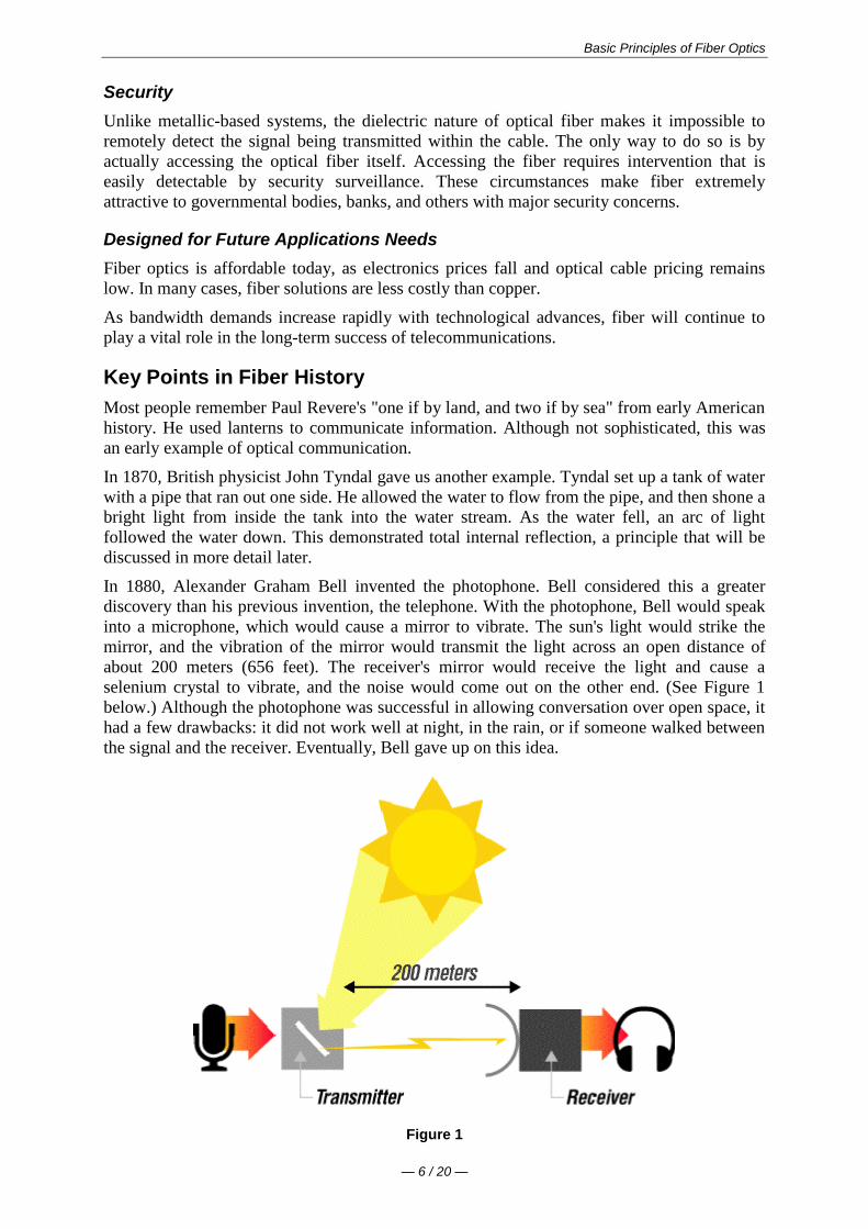
Basic Principles of Fiber Optics
mdash 6 20 mdash
Security
Unlike metallic-based systems the dielectric nature of optical fiber makes it impossible to
remotely detect the signal being transmitted within the cable The only way to do so is by
actually accessing the optical fiber itself Accessing the fiber requires intervention that is
easily detectable by security surveillance These circumstances make fiber extremely
attractive to governmental bodies banks and others with major security concerns
Designed for Future Applications Needs
Fiber optics is affordable today as electronics prices fall and optical cable pricing remains
low In many cases fiber solutions are less costly than copper
As bandwidth demands increase rapidly with technological advances fiber will continue to
play a vital role in the long-term success of telecommunications
Key Points in Fiber History
Most people remember Paul Reveres one if by land and two if by sea from early American
history He used lanterns to communicate information Although not sophisticated this was
an early example of optical communication
In 1870 British physicist John Tyndal gave us another example Tyndal set up a tank of water
with a pipe that ran out one side He allowed the water to flow from the pipe and then shone a
bright light from inside the tank into the water stream As the water fell an arc of light
followed the water down This demonstrated total internal reflection a principle that will be
discussed in more detail later
In 1880 Alexander Graham Bell invented the photophone Bell considered this a greater
discovery than his previous invention the telephone With the photophone Bell would speak
into a microphone which would cause a mirror to vibrate The suns light would strike the
mirror and the vibration of the mirror would transmit the light across an open distance of
about 200 meters (656 feet) The receivers mirror would receive the light and cause a
selenium crystal to vibrate and the noise would come out on the other end (See Figure 1
below) Although the photophone was successful in allowing conversation over open space it
had a few drawbacks it did not work well at night in the rain or if someone walked between
the signal and the receiver Eventually Bell gave up on this idea
Figure 1
Basic Principles of Fiber Optics
mdash 7 20 mdash
It wasnt until the late 1950s that the laser was invented This device was a finely-controlled
beam of light that could transmit information over long distances Unfortunately the same
drawbacks experienced by Alexander Graham Bell also plagued the laser Although it could
be used at night it didnt work during rain fog or any time a building was erected between
the sender and the receiver
Dr Robert Maurer Peter Schultz and Donald Keck of Corning Incorporated in Corning New
York came up with the first low loss optical fiber with less than 20 dBkm (decibels per
kilometer) loss (Today single-mode premium grade fiber is sold with specifications of 025
dBkm or better)
In 1977 Corning joined forces with another technological giant Siemens Corporation to
form Corning Cable Systems Cornings extensive work with fiber coupled with Siemens
cabling technology helped launch a new era in optical fiber cable and associated products
Today Corning Cable Systems is a world leader in the manufacture of fiber optic cabling
system products for voice data and video communications applications
Check Your Understanding
Would you like to see how much youve learned
1 In what decade did optical fiber communications become commercially viable
1870
1950
1970
1980
2 Which of the following is a good example of an optical fiber application for
telecommunications
Local or long-distance telephone communications
Medical instruments for orthoscopic surgery
Missile guidance and target tracking
3 Which of the following is not true about optical fiber transmission systems
Can be used for voice or data and video
Are almost always more expensive than copper
Easy to install and upgrade
Are virtually immune to electromagnetic and radio-frequency interference
Bibliography
Introduction to Basic Fiber Optics
Session Outline Corning Cable Systems 1994
Just the Facts
Corning Incorporated Corning New York 1993
Jeff Englebert et alOptical Fiber and Cable for Telecommunications
Corning Cable Systems 1996
TR-07-S Hands-On Fiber Optic Installation for Local Area Networks
Corning Cable Systems Hickory North Carolina 1989
Jeff Hecht Understanding Fiber Optics
Howard W Sams amp Company Carmel Indiana 1987
Basic Principles of Fiber Optics
mdash 8 20 mdash
Basic Principles of Operation
Figure 2
The Information Transmision Sequence
As depicted above information (voice data or video) is encoded into electrical signals At
the light source these electrical signals are converted into light signals
It is important to note that fiber has the capability to carry either analog or digital signals
Many people believe that fiber can transmit only digital signals due to the onoff binary
characteristic of the light source The intensity of the light and the frequency at which the
intensity changes can be used for AM and FM analog transmission
Once the signals are converted to light they travel down the fiber until they reach a detector
which changes the light signals back into electrical signals This area from light source to
detector constitutes the passive transmission subsystem ie that part of the system
manufactured and sold by Corning Cable Systems
Finally the electrical signals are decoded into information in the form of voice data or video
Cross Section of a Typical Fiber
Figure 3
Basic Principles of Fiber Optics
mdash 9 20 mdash
Optical fiber for telecommunications consists of three components core cladding amp coating
The core is the central region of an optical fiber through which light is transmitted In general
the telecommunications industry uses sizes from 83 micrometer (microm) to 625 micrometers
The standard telecommunications core sizes in use today are 83 microm (single-mode) 50 microm
(multimode) and 625 microm (multimode) (Single-mode and multimode will be discussed
shortly) The diameter of the cladding surrounding each of these cores is 125 microm Core sizes
of 85 microm and 100 microm have been used in early applications but are not typically used today
To put these sizes into perspective compare them to a human hair which is approximately 70
microm or 0003 inch
The core and cladding are manufactured together as a single piece of silica glass with slightly
different compositions and cannot be separated from one another The glass does not have a
hole in the core but is completely solid throughout
The third section of an optical fiber is the outer protective coating This coating is typically an
ultraviolet (UV) light-cured acrylate applied during the manufacturing process to provide
physical and environmental protection for the fiber During the installation process this
coating is stripped away from the cladding to allow proper termination to an optical
transmission system
The coating size can vary but the standard sizes are 250 microm or 900 microm The 250 microm coating
takes less space in larger outdoor cables The 900 microm coating is larger and more suitable for
smaller indoor cables
Types of Fiber
Once light enters an optical fiber it travels in a stable state called a mode There can be from
one to hundreds of modes depending on the type of fiber Each mode carries a portion of the
light from the input signal
Generally speaking the number of modes in a fiber is a function of the relationship between
core diameter numerical aperture and wavelength which will be discussed later in the text
Figure 4
Every telecommunications fiber falls into one of two categories single-mode or multimode
It is impossible to distinguish between single-mode and multimode fiber with the naked eye
There is no difference in outward appearance only in core size Both fiber types act as a
transmission medium for light but they operate in different ways have different
characteristics and serve different applications
Single-Mode (SM) fiber allows for only one pathway or mode of light to travel within the
fiber The core size is typically 83 microm Single-mode fibers are used in applications where low
signal loss and high data rates are required such as on long spans where repeateramplifier
spacing needs to be maximized
Basic Principles of Fiber Optics
mdash 10 20 mdash
Multimode (MM) fiber allows more than one mode of light Common MM core sizes are 50
microm and 625 microm Multimode fiber is better suited for shorter distance applications Where
costly electronics are heavily concentrated the primary cost of the system does not lie with
the cable In such a case MM fiber is more economical because it can be used with
inexpensive connectors and LED transmitters making the total system cost lower This makes
MM fiber the ideal choice for short distance lower bandwidth applications
Check Your Understanding
Would you like to see how much youve learned
1 What purpose does the core of an optical fiber serve
It protects the fiber from the environment
It carries light through the fiber
It separates the cladding and the coating
2 Which of the following is NOT true of single-mode fiber
It carries more information than multimode fiber
Its core is smaller than multimode fiber
It is hollow in the center
3 At installation which of the following is NOT true about optical fiber
The cladding and coating are stripped away
The fiber has the ability to carry either analog or digital signals
Light signals must enter the fiber within the acceptance cone to propagate
Applied Principles of Operation
Index of Refraction (IOR)
The index of refraction (IOR) is a way of measuring the speed of light in a material Light
travels fastest in a vacuum such as outer space The actual speed of light in a vacuum is
300000 kilometers per second or 186000 miles per second
Index of Refraction is calculated by dividing the speed of light in a vacuum by the speed of
light in some other medium
The Index of Refraction of a vacuum by definition has a value of 1
For the sake of simplicity typical values are provided here in Figure 5 Notice that the typical
value for the cladding of an optical fiber is 146 The core value is 148 The larger the index
of refraction the more slowly light travels in that medium
Figure 5
Basic Principles of Fiber Optics
mdash 11 20 mdash
Total Internal Refraction
When a light ray traveling in one material hits a different material and reflects back into the
original material without any loss of light total internal refraction occurs
Since the core and cladding are constructed from different compositions of glass
theoretically light entering the core is confined to the boundaries of the core because it
reflects back whenever it hits the cladding For total internal reflection to occur the index of
refraction of the core must be higher than that of the cladding
Acceptance Cone
As mentioned earlier electrical signals are converted to light signals before they enter an
optical fiber To ensure that the signals reflect and travel correctly through the core the light
must enter the core through an imaginary acceptance cone (See Figure 7 below) The size of
this acceptance cone is a function of the refractive index difference between the core and the
cladding
In simpler terms there is a maximum angle from the fiber axis at which light may enter the
fiber so that it will propagate or travel in the core of the fiber The sine of this maximum
angle is the numerical aperture (NA) of the fiber Fiber with a larger NA requires less
precision to splice and work with than fiber with a smaller NA Single-mode fiber has a small
NA
Check Your Understanding
Would you like to see how much youve learned
1 Which of the following is true of the index of refraction
It is a way of measuring the speed of light in a material
It is calculated by dividing the speed of light in some medium by the speed of light
in a vacuum
When calculated it shows that the fastest light speed occurs in air
2 Total internal reflection is
Reflection that occurs when a light ray traveling in one material hits another
material and reflects back into the original material without any loss of light
Basic Principles of Fiber Optics
mdash 12 20 mdash
Complete meditation without interruption
Reflection that occurs when the refractive index of the core is lower than the
cladding
Optical Fiber Parameters
As with any type of transmission system there are certain parameters that affect the systems
operation
Wavelength
Light that can be seen by the unaided human eye is said to be in the visible spectrum In the
visible spectrum wavelength can be described as the color of light
To put this into perspective take a look at Figure 8 Notice that the colors of the rainbow -
red orange yellow green blue (indigo not shown) and violet fall within the visible
spectrum
Figure 8
Basic Principles of Fiber Optics
mdash 13 20 mdash
Optical fiber transmission uses wavelengths which are above the visible light spectrum and
thus undetectable to the unaided eye Typical optical transmission wavelengths are 850
nanometers (nm) 1310 nm and 1550 nm
Both lasers and LEDs (light-emitting diodes) are used to transmit light through optical fiber
Lasers are usually used for 1310 or 1550 nanometer single-mode applications LEDs are
used for 850 or 1300 nanometer multimode applications
Safety note Never look into the end of a fiber which may have a laser coupled to it Laser
light is invisible and can damage the eyes Viewing it directly does not cause pain The iris of
the eye will not close involuntarily as when viewing a bright light consequently serious
damage to the retina of the eye is possible Should accidental exposure to laser light be
suspected an eye examination should be arranged immediately
Window
There are ranges of wavelengths at which the fiber operates best Each range is known as an
operating window Each window is centered around the typical operational wavelength
Figure 9
These wavelengths were chosen because they best match the transmission properties of
available light sources with the transmission qualities of optical fiber
Frequency
The frequency of a system is the speed of modulation of the digital or analog output of the
light source in other words the number of pulses per second emitted from the light source
Frequency is measured in units of hertz (Hz) where 1 hertz is equal to 1 pulse or cycle per
second (Figure 10) A more practical measurement for optical communications is megahertz
(MHz) or millions of pulses per second
Figure 10
Attenuation
Attenuation is the loss of optical power as light travels down a fiber It is measured in decibels
(dBkm) Over a set distance a fiber with a lower attenuation will allow more power to reach
its receiver than a fiber with higher attenuation
Basic Principles of Fiber Optics
mdash 14 20 mdash
While low-loss optical systems are always desirable it is possible to lose a large portion of
the initial signal power without significant problems A loss of 50 of initial power is equal
to a 30 dB loss Any time fibers are joined together there will be some loss Losses for fusion
splicing and for mechanical splicing are typically 02 dB or less
Attenuation can be caused by several factors but is generally placed in one of two categories
intrinsic or extrinsic
Intrinsic Attenuation
Intrinsic attenuation occurs due to something inside or inherent to the fiber It is caused by
impurities in the glass during the manufacturing process As precise as manufacturing is there
is no way to eliminate all impurities though technological advances have caused attenuation
to decrease dramatically since the first optical fiber in 1970
When a light signal hits an impurity in the fiber one of two things will occur it will scatter or
it will be absorbed
Scattering
Rayleigh scattering accounts for the majority (about 96) of attenuation in optical fiber
Light travels in the core and interacts with the atoms in the glass The light waves elastically
collide with the atoms and light is scattered as a result
Rayleigh scattering is the result of these elastic collisions between the light wave and the
atoms in the fiber If the scattered light maintains an angle that supports forward travel within
the core no attenuation occurs If the light is scattered at an angle that does not support
continued forward travel the light is diverted out of the core and attenuation occurs
Figure 11
Some scattered light is reflected back toward the light source (input end) This is a property
that is used in an Optical Time Domain Reflectometer (OTDR) to test fibers This same
principle applies to analyzing loss associated with localized events in the fiber such as
splices
Absorption
The second type of intrinsic attenuation in fiber is absorption Absorption accounts for 3-5
of fiber attenuation This phenomenon causes a light signal to be absorbed by natural
impurities in the glass and converted to vibrational energy or some other form of energy
(Figure 12)
Unlike scattering absorption can be limited by controlling the amount of impurities during
the manufacturing process
Basic Principles of Fiber Optics
mdash 15 20 mdash
Figure 12
Extrinsic Attenuation
The second category of attenuation is extrinsic attenuation Extrinsic attenuation can be
caused by two external mechanisms macrobending or microbending Both cause a reduction
of optical power
Macrobending
If a bend is imposed on an optical fiber strain is placed on the fiber along the region that is
bent The bending strain will affect the refractive index and the critical angle of the light ray
in that specific area As a result light traveling in the core can refract out and loss occurs
(Figure 13)
A macrobend is a large-scale bend that is visible for example a fiber wrapped around a
persons finger This loss is generally reversible once bends are corrected
To prevent macrobends all optical fiber (and optical fiber cable) has a minimum bend radius
specification that should not be exceeded This is a restriction on how much bend a fiber can
withstand before experiencing problems in optical performance or mechanical reliability The
rule of thumb for minimum bend radius is 1 12 for bare single-mode fiber 10 times the
cables outside diameter (OD) for non-armored cable and 15 times the cables OD for
armored cable
Figure 13
Microbending
The second extrinsic cause of attenuation is a microbend This is a small-scale distortion
generally indicative of pressure on the fiber (See Figure 14 below) Microbending may be
related to temperature tensile stress or crushing force Like macrobending microbending
will cause a reduction of optical power in the glass
Microbending is very localized and the bend may not be clearly visible upon inspection With
bare fiber microbending may be reversible in the cabling process it may not
Basic Principles of Fiber Optics
mdash 16 20 mdash
Figure 14
Dispersion
Dispersion is the spreading of a light pulse as it travels down a fiber (See Figure 15) As
the pulses spread or broaden they tend to overlap and are no longer distinguishable by the
receiver as 0s and 1s Light pulses launched close together (high data rates) that spread too
much (high dispersion) result in errors and loss of information
Chromatic dispersion occurs as a result of the range of wavelengths in the light source Light
from lasers and LEDs consists of a range of wavelengths Each of these wavelengths travels at
a slightly different speed Over distance the varying wavelength speeds cause the light pulse
to spread in time This is of most importance in single-mode applications
Modal dispersion is significant in multimode applications where the various modes of light
traveling down the fiber arrive at the receiver at different times causing a spreading effect
Figure 15
Pulse width is measured at full width-half maximum in other words the full width of the
pulse at half the maximum pulse height Dispersion limits how fast or how much
information can be sent over an optical fiber
There are other effects of dispersion but further discussion is beyond the scope of this text
For more in-depth reading please consult the bibliography at the end of this publication
Bandwidth
In simplest terms bandwidth is the amount of information a fiber can carry so that every pulse
is distinguishable by the receiver at the end (Figure 16)
Basic Principles of Fiber Optics
mdash 17 20 mdash
Figure 16
As discussed in the previous section dispersion causes light pulses to spread The spreading
of these light pulses causes them to merge together At a certain distance and frequency the
pulses become unreadable by the receiver The multiple pathways of a multimode fiber cause
this overlap to be much greater than for single-mode fiber These different paths have
different lengths which cause each mode of light to arrive at a different time
System bandwidth is measured in megahertz (MHz) at one km In general when a systems
bandwidth is 200 MHzmiddotkm it means that 200 million pulses of light per second will travel
down 1 km (1000 meters) of fiber and each pulse will be distinguishable by the receiver
Check Your Understanding
Would you like to see how much youve learned
1 In optical fiber systems what are the typical wavelengths of operation
400 nm 455 nm 490 nm
620 nm 750 nm 800 nm
850 nm 1310 nm 1550 nm
2 What is an optical window
A glass object on the side of a building
A range of wavelengths at which fiber best operates
The moment in time when fiber became a commercially-viable enterprise
3 Which of the following is not true of attenuation
It is the loss of optical power as light travels down a fiber
It may be induced by scattering absorbing macrobending and microbending
It is measured in nanometers
4 What is bandwidth
A measure of the information-carrying capacity of an optical fiber
The side-to-side measurement of a wedding ring
A term used to express the total loss of an optical system
Fiber Manufacturing
There are several ways to manufacture optical fiber but this text will concentrate on the
method developed patented and used by the former Corning Glass Works now Corning
Incorporated
This method called Outside Vapor Deposition or OVD has three steps or phases laydown
consolidation and draw
Basic Principles of Fiber Optics
mdash 18 20 mdash
Laydown
In the laydown step a soot preform is made from ultrapure vapors of silicon tetrachloride and
germanium tetrachloride The vapors travel through a traversing burner and react in the flame
to form soot particles of silica and germania
Figure 17
The OVD process is distinguished by the method of depositing the soot These particles are
deposited on the surface of a rotating target rod The core material is deposited first followed
by the pure silica cladding Since both core and cladding raw materials are vapor-deposited
the entire preform is extremely pure
Consolidation
When deposition is complete the target rod is removed from the center of the porous preform
and the preform is placed into a consolidation furnace During the consolidation process the
water vapor is removed from the preform This high-temperature consolidation step sinters the
preform into a solid dense transparent glass blank The hole left by the target rod is fused
solid by the extremely high temperature of the draw furnace
Draw
The finished glass preform is placed in a draw tower and drawn into a continuous strand of
glass fiber First the blank is lowered into the top of the draw furnace
Basic Principles of Fiber Optics
mdash 19 20 mdash
Figure 18
The tip of the blank is heated until a piece of molten glass called a gob begins to fall from
the blank like hot taffy It pulls a thin strand of glass the beginning of an optical fiber
The fiber goes through a precise on-line diameter monitor to ensure specified outside
diameter Next coatings are applied and cured using ultraviolet lamps
At the bottom of the draw the fiber is wound on spools Each fiber is assigned a unique
identification number that encodes all relevant manufacturing data including raw materials
and manufacturing equipment
Note Extensive text and graphics in this Fiber Manufacturing section are used with
permission of Corning Communications
Check Your Understanding
Would you like to see how much youve learned
1 What are the three steps of fiber manufacture using the Outside Vapor Deposition (OVD)
method
Burner vapor fuel
Laydown consolidation draw
Gas glass spool
2 Which of the following is NOT true about the laydown stage of OVD fiber manufacture
A rotating target rod collects soot deposited from the burner
Basic Principles of Fiber Optics
mdash 20 20 mdash
The soot forms a preform
The preform is highly impure until it reaches the consolidation phase
3 Which of the following is NOT true about the consolidation stage of fiber manufacture
The removal of the target rod causes the core of the fiber to be hollow
Water vapor is removed from the preform
The white preform becomes a solid dense transparent glass blank
4 Which of the following is NOT true about the draw stage of fiber manufacture
The glass preform is drawn into a continuous piece of glass fiber
Fiber diameters are measured on-line
Coatings are applied and cured using infrared lamps
Basic Principles of Fiber Optics
mdash 7 20 mdash
It wasnt until the late 1950s that the laser was invented This device was a finely-controlled
beam of light that could transmit information over long distances Unfortunately the same
drawbacks experienced by Alexander Graham Bell also plagued the laser Although it could
be used at night it didnt work during rain fog or any time a building was erected between
the sender and the receiver
Dr Robert Maurer Peter Schultz and Donald Keck of Corning Incorporated in Corning New
York came up with the first low loss optical fiber with less than 20 dBkm (decibels per
kilometer) loss (Today single-mode premium grade fiber is sold with specifications of 025
dBkm or better)
In 1977 Corning joined forces with another technological giant Siemens Corporation to
form Corning Cable Systems Cornings extensive work with fiber coupled with Siemens
cabling technology helped launch a new era in optical fiber cable and associated products
Today Corning Cable Systems is a world leader in the manufacture of fiber optic cabling
system products for voice data and video communications applications
Check Your Understanding
Would you like to see how much youve learned
1 In what decade did optical fiber communications become commercially viable
1870
1950
1970
1980
2 Which of the following is a good example of an optical fiber application for
telecommunications
Local or long-distance telephone communications
Medical instruments for orthoscopic surgery
Missile guidance and target tracking
3 Which of the following is not true about optical fiber transmission systems
Can be used for voice or data and video
Are almost always more expensive than copper
Easy to install and upgrade
Are virtually immune to electromagnetic and radio-frequency interference
Bibliography
Introduction to Basic Fiber Optics
Session Outline Corning Cable Systems 1994
Just the Facts
Corning Incorporated Corning New York 1993
Jeff Englebert et alOptical Fiber and Cable for Telecommunications
Corning Cable Systems 1996
TR-07-S Hands-On Fiber Optic Installation for Local Area Networks
Corning Cable Systems Hickory North Carolina 1989
Jeff Hecht Understanding Fiber Optics
Howard W Sams amp Company Carmel Indiana 1987
Basic Principles of Fiber Optics
mdash 8 20 mdash
Basic Principles of Operation
Figure 2
The Information Transmision Sequence
As depicted above information (voice data or video) is encoded into electrical signals At
the light source these electrical signals are converted into light signals
It is important to note that fiber has the capability to carry either analog or digital signals
Many people believe that fiber can transmit only digital signals due to the onoff binary
characteristic of the light source The intensity of the light and the frequency at which the
intensity changes can be used for AM and FM analog transmission
Once the signals are converted to light they travel down the fiber until they reach a detector
which changes the light signals back into electrical signals This area from light source to
detector constitutes the passive transmission subsystem ie that part of the system
manufactured and sold by Corning Cable Systems
Finally the electrical signals are decoded into information in the form of voice data or video
Cross Section of a Typical Fiber
Figure 3
Basic Principles of Fiber Optics
mdash 9 20 mdash
Optical fiber for telecommunications consists of three components core cladding amp coating
The core is the central region of an optical fiber through which light is transmitted In general
the telecommunications industry uses sizes from 83 micrometer (microm) to 625 micrometers
The standard telecommunications core sizes in use today are 83 microm (single-mode) 50 microm
(multimode) and 625 microm (multimode) (Single-mode and multimode will be discussed
shortly) The diameter of the cladding surrounding each of these cores is 125 microm Core sizes
of 85 microm and 100 microm have been used in early applications but are not typically used today
To put these sizes into perspective compare them to a human hair which is approximately 70
microm or 0003 inch
The core and cladding are manufactured together as a single piece of silica glass with slightly
different compositions and cannot be separated from one another The glass does not have a
hole in the core but is completely solid throughout
The third section of an optical fiber is the outer protective coating This coating is typically an
ultraviolet (UV) light-cured acrylate applied during the manufacturing process to provide
physical and environmental protection for the fiber During the installation process this
coating is stripped away from the cladding to allow proper termination to an optical
transmission system
The coating size can vary but the standard sizes are 250 microm or 900 microm The 250 microm coating
takes less space in larger outdoor cables The 900 microm coating is larger and more suitable for
smaller indoor cables
Types of Fiber
Once light enters an optical fiber it travels in a stable state called a mode There can be from
one to hundreds of modes depending on the type of fiber Each mode carries a portion of the
light from the input signal
Generally speaking the number of modes in a fiber is a function of the relationship between
core diameter numerical aperture and wavelength which will be discussed later in the text
Figure 4
Every telecommunications fiber falls into one of two categories single-mode or multimode
It is impossible to distinguish between single-mode and multimode fiber with the naked eye
There is no difference in outward appearance only in core size Both fiber types act as a
transmission medium for light but they operate in different ways have different
characteristics and serve different applications
Single-Mode (SM) fiber allows for only one pathway or mode of light to travel within the
fiber The core size is typically 83 microm Single-mode fibers are used in applications where low
signal loss and high data rates are required such as on long spans where repeateramplifier
spacing needs to be maximized
Basic Principles of Fiber Optics
mdash 10 20 mdash
Multimode (MM) fiber allows more than one mode of light Common MM core sizes are 50
microm and 625 microm Multimode fiber is better suited for shorter distance applications Where
costly electronics are heavily concentrated the primary cost of the system does not lie with
the cable In such a case MM fiber is more economical because it can be used with
inexpensive connectors and LED transmitters making the total system cost lower This makes
MM fiber the ideal choice for short distance lower bandwidth applications
Check Your Understanding
Would you like to see how much youve learned
1 What purpose does the core of an optical fiber serve
It protects the fiber from the environment
It carries light through the fiber
It separates the cladding and the coating
2 Which of the following is NOT true of single-mode fiber
It carries more information than multimode fiber
Its core is smaller than multimode fiber
It is hollow in the center
3 At installation which of the following is NOT true about optical fiber
The cladding and coating are stripped away
The fiber has the ability to carry either analog or digital signals
Light signals must enter the fiber within the acceptance cone to propagate
Applied Principles of Operation
Index of Refraction (IOR)
The index of refraction (IOR) is a way of measuring the speed of light in a material Light
travels fastest in a vacuum such as outer space The actual speed of light in a vacuum is
300000 kilometers per second or 186000 miles per second
Index of Refraction is calculated by dividing the speed of light in a vacuum by the speed of
light in some other medium
The Index of Refraction of a vacuum by definition has a value of 1
For the sake of simplicity typical values are provided here in Figure 5 Notice that the typical
value for the cladding of an optical fiber is 146 The core value is 148 The larger the index
of refraction the more slowly light travels in that medium
Figure 5
Basic Principles of Fiber Optics
mdash 11 20 mdash
Total Internal Refraction
When a light ray traveling in one material hits a different material and reflects back into the
original material without any loss of light total internal refraction occurs
Since the core and cladding are constructed from different compositions of glass
theoretically light entering the core is confined to the boundaries of the core because it
reflects back whenever it hits the cladding For total internal reflection to occur the index of
refraction of the core must be higher than that of the cladding
Acceptance Cone
As mentioned earlier electrical signals are converted to light signals before they enter an
optical fiber To ensure that the signals reflect and travel correctly through the core the light
must enter the core through an imaginary acceptance cone (See Figure 7 below) The size of
this acceptance cone is a function of the refractive index difference between the core and the
cladding
In simpler terms there is a maximum angle from the fiber axis at which light may enter the
fiber so that it will propagate or travel in the core of the fiber The sine of this maximum
angle is the numerical aperture (NA) of the fiber Fiber with a larger NA requires less
precision to splice and work with than fiber with a smaller NA Single-mode fiber has a small
NA
Check Your Understanding
Would you like to see how much youve learned
1 Which of the following is true of the index of refraction
It is a way of measuring the speed of light in a material
It is calculated by dividing the speed of light in some medium by the speed of light
in a vacuum
When calculated it shows that the fastest light speed occurs in air
2 Total internal reflection is
Reflection that occurs when a light ray traveling in one material hits another
material and reflects back into the original material without any loss of light
Basic Principles of Fiber Optics
mdash 12 20 mdash
Complete meditation without interruption
Reflection that occurs when the refractive index of the core is lower than the
cladding
Optical Fiber Parameters
As with any type of transmission system there are certain parameters that affect the systems
operation
Wavelength
Light that can be seen by the unaided human eye is said to be in the visible spectrum In the
visible spectrum wavelength can be described as the color of light
To put this into perspective take a look at Figure 8 Notice that the colors of the rainbow -
red orange yellow green blue (indigo not shown) and violet fall within the visible
spectrum
Figure 8
Basic Principles of Fiber Optics
mdash 13 20 mdash
Optical fiber transmission uses wavelengths which are above the visible light spectrum and
thus undetectable to the unaided eye Typical optical transmission wavelengths are 850
nanometers (nm) 1310 nm and 1550 nm
Both lasers and LEDs (light-emitting diodes) are used to transmit light through optical fiber
Lasers are usually used for 1310 or 1550 nanometer single-mode applications LEDs are
used for 850 or 1300 nanometer multimode applications
Safety note Never look into the end of a fiber which may have a laser coupled to it Laser
light is invisible and can damage the eyes Viewing it directly does not cause pain The iris of
the eye will not close involuntarily as when viewing a bright light consequently serious
damage to the retina of the eye is possible Should accidental exposure to laser light be
suspected an eye examination should be arranged immediately
Window
There are ranges of wavelengths at which the fiber operates best Each range is known as an
operating window Each window is centered around the typical operational wavelength
Figure 9
These wavelengths were chosen because they best match the transmission properties of
available light sources with the transmission qualities of optical fiber
Frequency
The frequency of a system is the speed of modulation of the digital or analog output of the
light source in other words the number of pulses per second emitted from the light source
Frequency is measured in units of hertz (Hz) where 1 hertz is equal to 1 pulse or cycle per
second (Figure 10) A more practical measurement for optical communications is megahertz
(MHz) or millions of pulses per second
Figure 10
Attenuation
Attenuation is the loss of optical power as light travels down a fiber It is measured in decibels
(dBkm) Over a set distance a fiber with a lower attenuation will allow more power to reach
its receiver than a fiber with higher attenuation
Basic Principles of Fiber Optics
mdash 14 20 mdash
While low-loss optical systems are always desirable it is possible to lose a large portion of
the initial signal power without significant problems A loss of 50 of initial power is equal
to a 30 dB loss Any time fibers are joined together there will be some loss Losses for fusion
splicing and for mechanical splicing are typically 02 dB or less
Attenuation can be caused by several factors but is generally placed in one of two categories
intrinsic or extrinsic
Intrinsic Attenuation
Intrinsic attenuation occurs due to something inside or inherent to the fiber It is caused by
impurities in the glass during the manufacturing process As precise as manufacturing is there
is no way to eliminate all impurities though technological advances have caused attenuation
to decrease dramatically since the first optical fiber in 1970
When a light signal hits an impurity in the fiber one of two things will occur it will scatter or
it will be absorbed
Scattering
Rayleigh scattering accounts for the majority (about 96) of attenuation in optical fiber
Light travels in the core and interacts with the atoms in the glass The light waves elastically
collide with the atoms and light is scattered as a result
Rayleigh scattering is the result of these elastic collisions between the light wave and the
atoms in the fiber If the scattered light maintains an angle that supports forward travel within
the core no attenuation occurs If the light is scattered at an angle that does not support
continued forward travel the light is diverted out of the core and attenuation occurs
Figure 11
Some scattered light is reflected back toward the light source (input end) This is a property
that is used in an Optical Time Domain Reflectometer (OTDR) to test fibers This same
principle applies to analyzing loss associated with localized events in the fiber such as
splices
Absorption
The second type of intrinsic attenuation in fiber is absorption Absorption accounts for 3-5
of fiber attenuation This phenomenon causes a light signal to be absorbed by natural
impurities in the glass and converted to vibrational energy or some other form of energy
(Figure 12)
Unlike scattering absorption can be limited by controlling the amount of impurities during
the manufacturing process
Basic Principles of Fiber Optics
mdash 15 20 mdash
Figure 12
Extrinsic Attenuation
The second category of attenuation is extrinsic attenuation Extrinsic attenuation can be
caused by two external mechanisms macrobending or microbending Both cause a reduction
of optical power
Macrobending
If a bend is imposed on an optical fiber strain is placed on the fiber along the region that is
bent The bending strain will affect the refractive index and the critical angle of the light ray
in that specific area As a result light traveling in the core can refract out and loss occurs
(Figure 13)
A macrobend is a large-scale bend that is visible for example a fiber wrapped around a
persons finger This loss is generally reversible once bends are corrected
To prevent macrobends all optical fiber (and optical fiber cable) has a minimum bend radius
specification that should not be exceeded This is a restriction on how much bend a fiber can
withstand before experiencing problems in optical performance or mechanical reliability The
rule of thumb for minimum bend radius is 1 12 for bare single-mode fiber 10 times the
cables outside diameter (OD) for non-armored cable and 15 times the cables OD for
armored cable
Figure 13
Microbending
The second extrinsic cause of attenuation is a microbend This is a small-scale distortion
generally indicative of pressure on the fiber (See Figure 14 below) Microbending may be
related to temperature tensile stress or crushing force Like macrobending microbending
will cause a reduction of optical power in the glass
Microbending is very localized and the bend may not be clearly visible upon inspection With
bare fiber microbending may be reversible in the cabling process it may not
Basic Principles of Fiber Optics
mdash 16 20 mdash
Figure 14
Dispersion
Dispersion is the spreading of a light pulse as it travels down a fiber (See Figure 15) As
the pulses spread or broaden they tend to overlap and are no longer distinguishable by the
receiver as 0s and 1s Light pulses launched close together (high data rates) that spread too
much (high dispersion) result in errors and loss of information
Chromatic dispersion occurs as a result of the range of wavelengths in the light source Light
from lasers and LEDs consists of a range of wavelengths Each of these wavelengths travels at
a slightly different speed Over distance the varying wavelength speeds cause the light pulse
to spread in time This is of most importance in single-mode applications
Modal dispersion is significant in multimode applications where the various modes of light
traveling down the fiber arrive at the receiver at different times causing a spreading effect
Figure 15
Pulse width is measured at full width-half maximum in other words the full width of the
pulse at half the maximum pulse height Dispersion limits how fast or how much
information can be sent over an optical fiber
There are other effects of dispersion but further discussion is beyond the scope of this text
For more in-depth reading please consult the bibliography at the end of this publication
Bandwidth
In simplest terms bandwidth is the amount of information a fiber can carry so that every pulse
is distinguishable by the receiver at the end (Figure 16)
Basic Principles of Fiber Optics
mdash 17 20 mdash
Figure 16
As discussed in the previous section dispersion causes light pulses to spread The spreading
of these light pulses causes them to merge together At a certain distance and frequency the
pulses become unreadable by the receiver The multiple pathways of a multimode fiber cause
this overlap to be much greater than for single-mode fiber These different paths have
different lengths which cause each mode of light to arrive at a different time
System bandwidth is measured in megahertz (MHz) at one km In general when a systems
bandwidth is 200 MHzmiddotkm it means that 200 million pulses of light per second will travel
down 1 km (1000 meters) of fiber and each pulse will be distinguishable by the receiver
Check Your Understanding
Would you like to see how much youve learned
1 In optical fiber systems what are the typical wavelengths of operation
400 nm 455 nm 490 nm
620 nm 750 nm 800 nm
850 nm 1310 nm 1550 nm
2 What is an optical window
A glass object on the side of a building
A range of wavelengths at which fiber best operates
The moment in time when fiber became a commercially-viable enterprise
3 Which of the following is not true of attenuation
It is the loss of optical power as light travels down a fiber
It may be induced by scattering absorbing macrobending and microbending
It is measured in nanometers
4 What is bandwidth
A measure of the information-carrying capacity of an optical fiber
The side-to-side measurement of a wedding ring
A term used to express the total loss of an optical system
Fiber Manufacturing
There are several ways to manufacture optical fiber but this text will concentrate on the
method developed patented and used by the former Corning Glass Works now Corning
Incorporated
This method called Outside Vapor Deposition or OVD has three steps or phases laydown
consolidation and draw
Basic Principles of Fiber Optics
mdash 18 20 mdash
Laydown
In the laydown step a soot preform is made from ultrapure vapors of silicon tetrachloride and
germanium tetrachloride The vapors travel through a traversing burner and react in the flame
to form soot particles of silica and germania
Figure 17
The OVD process is distinguished by the method of depositing the soot These particles are
deposited on the surface of a rotating target rod The core material is deposited first followed
by the pure silica cladding Since both core and cladding raw materials are vapor-deposited
the entire preform is extremely pure
Consolidation
When deposition is complete the target rod is removed from the center of the porous preform
and the preform is placed into a consolidation furnace During the consolidation process the
water vapor is removed from the preform This high-temperature consolidation step sinters the
preform into a solid dense transparent glass blank The hole left by the target rod is fused
solid by the extremely high temperature of the draw furnace
Draw
The finished glass preform is placed in a draw tower and drawn into a continuous strand of
glass fiber First the blank is lowered into the top of the draw furnace
Basic Principles of Fiber Optics
mdash 19 20 mdash
Figure 18
The tip of the blank is heated until a piece of molten glass called a gob begins to fall from
the blank like hot taffy It pulls a thin strand of glass the beginning of an optical fiber
The fiber goes through a precise on-line diameter monitor to ensure specified outside
diameter Next coatings are applied and cured using ultraviolet lamps
At the bottom of the draw the fiber is wound on spools Each fiber is assigned a unique
identification number that encodes all relevant manufacturing data including raw materials
and manufacturing equipment
Note Extensive text and graphics in this Fiber Manufacturing section are used with
permission of Corning Communications
Check Your Understanding
Would you like to see how much youve learned
1 What are the three steps of fiber manufacture using the Outside Vapor Deposition (OVD)
method
Burner vapor fuel
Laydown consolidation draw
Gas glass spool
2 Which of the following is NOT true about the laydown stage of OVD fiber manufacture
A rotating target rod collects soot deposited from the burner
Basic Principles of Fiber Optics
mdash 20 20 mdash
The soot forms a preform
The preform is highly impure until it reaches the consolidation phase
3 Which of the following is NOT true about the consolidation stage of fiber manufacture
The removal of the target rod causes the core of the fiber to be hollow
Water vapor is removed from the preform
The white preform becomes a solid dense transparent glass blank
4 Which of the following is NOT true about the draw stage of fiber manufacture
The glass preform is drawn into a continuous piece of glass fiber
Fiber diameters are measured on-line
Coatings are applied and cured using infrared lamps
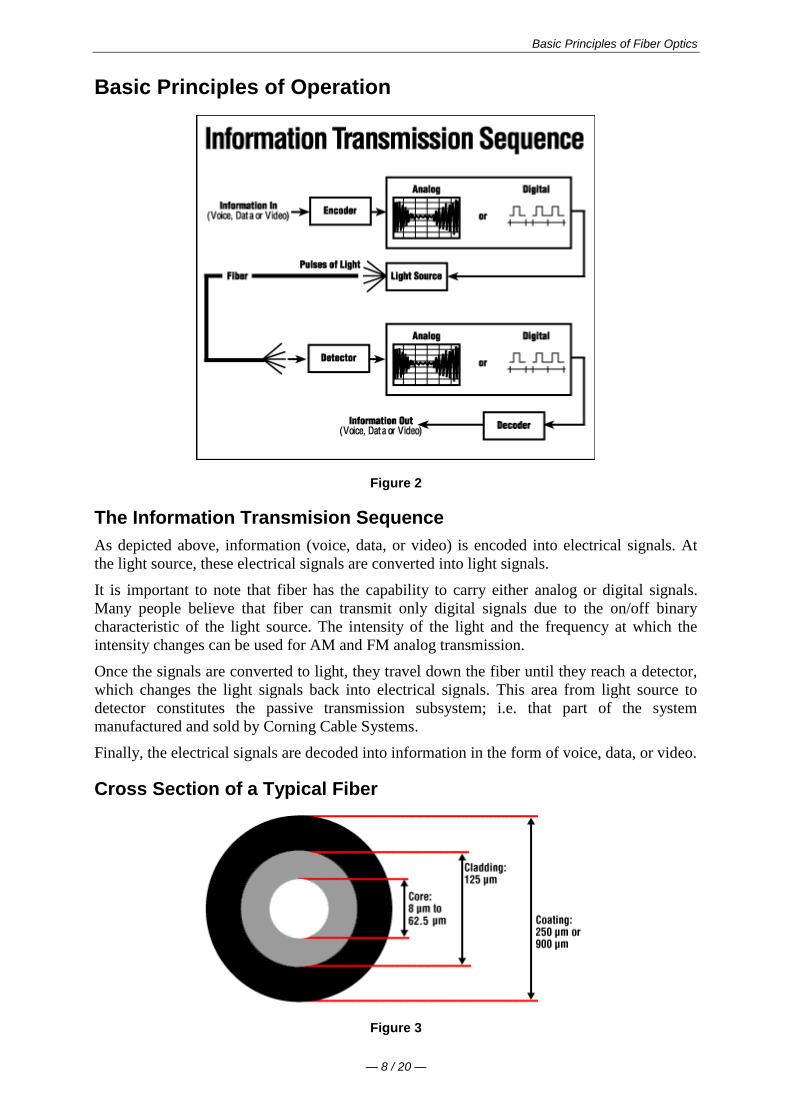
Basic Principles of Fiber Optics
mdash 8 20 mdash
Basic Principles of Operation
Figure 2
The Information Transmision Sequence
As depicted above information (voice data or video) is encoded into electrical signals At
the light source these electrical signals are converted into light signals
It is important to note that fiber has the capability to carry either analog or digital signals
Many people believe that fiber can transmit only digital signals due to the onoff binary
characteristic of the light source The intensity of the light and the frequency at which the
intensity changes can be used for AM and FM analog transmission
Once the signals are converted to light they travel down the fiber until they reach a detector
which changes the light signals back into electrical signals This area from light source to
detector constitutes the passive transmission subsystem ie that part of the system
manufactured and sold by Corning Cable Systems
Finally the electrical signals are decoded into information in the form of voice data or video
Cross Section of a Typical Fiber
Figure 3
Basic Principles of Fiber Optics
mdash 9 20 mdash
Optical fiber for telecommunications consists of three components core cladding amp coating
The core is the central region of an optical fiber through which light is transmitted In general
the telecommunications industry uses sizes from 83 micrometer (microm) to 625 micrometers
The standard telecommunications core sizes in use today are 83 microm (single-mode) 50 microm
(multimode) and 625 microm (multimode) (Single-mode and multimode will be discussed
shortly) The diameter of the cladding surrounding each of these cores is 125 microm Core sizes
of 85 microm and 100 microm have been used in early applications but are not typically used today
To put these sizes into perspective compare them to a human hair which is approximately 70
microm or 0003 inch
The core and cladding are manufactured together as a single piece of silica glass with slightly
different compositions and cannot be separated from one another The glass does not have a
hole in the core but is completely solid throughout
The third section of an optical fiber is the outer protective coating This coating is typically an
ultraviolet (UV) light-cured acrylate applied during the manufacturing process to provide
physical and environmental protection for the fiber During the installation process this
coating is stripped away from the cladding to allow proper termination to an optical
transmission system
The coating size can vary but the standard sizes are 250 microm or 900 microm The 250 microm coating
takes less space in larger outdoor cables The 900 microm coating is larger and more suitable for
smaller indoor cables
Types of Fiber
Once light enters an optical fiber it travels in a stable state called a mode There can be from
one to hundreds of modes depending on the type of fiber Each mode carries a portion of the
light from the input signal
Generally speaking the number of modes in a fiber is a function of the relationship between
core diameter numerical aperture and wavelength which will be discussed later in the text
Figure 4
Every telecommunications fiber falls into one of two categories single-mode or multimode
It is impossible to distinguish between single-mode and multimode fiber with the naked eye
There is no difference in outward appearance only in core size Both fiber types act as a
transmission medium for light but they operate in different ways have different
characteristics and serve different applications
Single-Mode (SM) fiber allows for only one pathway or mode of light to travel within the
fiber The core size is typically 83 microm Single-mode fibers are used in applications where low
signal loss and high data rates are required such as on long spans where repeateramplifier
spacing needs to be maximized
Basic Principles of Fiber Optics
mdash 10 20 mdash
Multimode (MM) fiber allows more than one mode of light Common MM core sizes are 50
microm and 625 microm Multimode fiber is better suited for shorter distance applications Where
costly electronics are heavily concentrated the primary cost of the system does not lie with
the cable In such a case MM fiber is more economical because it can be used with
inexpensive connectors and LED transmitters making the total system cost lower This makes
MM fiber the ideal choice for short distance lower bandwidth applications
Check Your Understanding
Would you like to see how much youve learned
1 What purpose does the core of an optical fiber serve
It protects the fiber from the environment
It carries light through the fiber
It separates the cladding and the coating
2 Which of the following is NOT true of single-mode fiber
It carries more information than multimode fiber
Its core is smaller than multimode fiber
It is hollow in the center
3 At installation which of the following is NOT true about optical fiber
The cladding and coating are stripped away
The fiber has the ability to carry either analog or digital signals
Light signals must enter the fiber within the acceptance cone to propagate
Applied Principles of Operation
Index of Refraction (IOR)
The index of refraction (IOR) is a way of measuring the speed of light in a material Light
travels fastest in a vacuum such as outer space The actual speed of light in a vacuum is
300000 kilometers per second or 186000 miles per second
Index of Refraction is calculated by dividing the speed of light in a vacuum by the speed of
light in some other medium
The Index of Refraction of a vacuum by definition has a value of 1
For the sake of simplicity typical values are provided here in Figure 5 Notice that the typical
value for the cladding of an optical fiber is 146 The core value is 148 The larger the index
of refraction the more slowly light travels in that medium
Figure 5
Basic Principles of Fiber Optics
mdash 11 20 mdash
Total Internal Refraction
When a light ray traveling in one material hits a different material and reflects back into the
original material without any loss of light total internal refraction occurs
Since the core and cladding are constructed from different compositions of glass
theoretically light entering the core is confined to the boundaries of the core because it
reflects back whenever it hits the cladding For total internal reflection to occur the index of
refraction of the core must be higher than that of the cladding
Acceptance Cone
As mentioned earlier electrical signals are converted to light signals before they enter an
optical fiber To ensure that the signals reflect and travel correctly through the core the light
must enter the core through an imaginary acceptance cone (See Figure 7 below) The size of
this acceptance cone is a function of the refractive index difference between the core and the
cladding
In simpler terms there is a maximum angle from the fiber axis at which light may enter the
fiber so that it will propagate or travel in the core of the fiber The sine of this maximum
angle is the numerical aperture (NA) of the fiber Fiber with a larger NA requires less
precision to splice and work with than fiber with a smaller NA Single-mode fiber has a small
NA
Check Your Understanding
Would you like to see how much youve learned
1 Which of the following is true of the index of refraction
It is a way of measuring the speed of light in a material
It is calculated by dividing the speed of light in some medium by the speed of light
in a vacuum
When calculated it shows that the fastest light speed occurs in air
2 Total internal reflection is
Reflection that occurs when a light ray traveling in one material hits another
material and reflects back into the original material without any loss of light
Basic Principles of Fiber Optics
mdash 12 20 mdash
Complete meditation without interruption
Reflection that occurs when the refractive index of the core is lower than the
cladding
Optical Fiber Parameters
As with any type of transmission system there are certain parameters that affect the systems
operation
Wavelength
Light that can be seen by the unaided human eye is said to be in the visible spectrum In the
visible spectrum wavelength can be described as the color of light
To put this into perspective take a look at Figure 8 Notice that the colors of the rainbow -
red orange yellow green blue (indigo not shown) and violet fall within the visible
spectrum
Figure 8
Basic Principles of Fiber Optics
mdash 13 20 mdash
Optical fiber transmission uses wavelengths which are above the visible light spectrum and
thus undetectable to the unaided eye Typical optical transmission wavelengths are 850
nanometers (nm) 1310 nm and 1550 nm
Both lasers and LEDs (light-emitting diodes) are used to transmit light through optical fiber
Lasers are usually used for 1310 or 1550 nanometer single-mode applications LEDs are
used for 850 or 1300 nanometer multimode applications
Safety note Never look into the end of a fiber which may have a laser coupled to it Laser
light is invisible and can damage the eyes Viewing it directly does not cause pain The iris of
the eye will not close involuntarily as when viewing a bright light consequently serious
damage to the retina of the eye is possible Should accidental exposure to laser light be
suspected an eye examination should be arranged immediately
Window
There are ranges of wavelengths at which the fiber operates best Each range is known as an
operating window Each window is centered around the typical operational wavelength
Figure 9
These wavelengths were chosen because they best match the transmission properties of
available light sources with the transmission qualities of optical fiber
Frequency
The frequency of a system is the speed of modulation of the digital or analog output of the
light source in other words the number of pulses per second emitted from the light source
Frequency is measured in units of hertz (Hz) where 1 hertz is equal to 1 pulse or cycle per
second (Figure 10) A more practical measurement for optical communications is megahertz
(MHz) or millions of pulses per second
Figure 10
Attenuation
Attenuation is the loss of optical power as light travels down a fiber It is measured in decibels
(dBkm) Over a set distance a fiber with a lower attenuation will allow more power to reach
its receiver than a fiber with higher attenuation
Basic Principles of Fiber Optics
mdash 14 20 mdash
While low-loss optical systems are always desirable it is possible to lose a large portion of
the initial signal power without significant problems A loss of 50 of initial power is equal
to a 30 dB loss Any time fibers are joined together there will be some loss Losses for fusion
splicing and for mechanical splicing are typically 02 dB or less
Attenuation can be caused by several factors but is generally placed in one of two categories
intrinsic or extrinsic
Intrinsic Attenuation
Intrinsic attenuation occurs due to something inside or inherent to the fiber It is caused by
impurities in the glass during the manufacturing process As precise as manufacturing is there
is no way to eliminate all impurities though technological advances have caused attenuation
to decrease dramatically since the first optical fiber in 1970
When a light signal hits an impurity in the fiber one of two things will occur it will scatter or
it will be absorbed
Scattering
Rayleigh scattering accounts for the majority (about 96) of attenuation in optical fiber
Light travels in the core and interacts with the atoms in the glass The light waves elastically
collide with the atoms and light is scattered as a result
Rayleigh scattering is the result of these elastic collisions between the light wave and the
atoms in the fiber If the scattered light maintains an angle that supports forward travel within
the core no attenuation occurs If the light is scattered at an angle that does not support
continued forward travel the light is diverted out of the core and attenuation occurs
Figure 11
Some scattered light is reflected back toward the light source (input end) This is a property
that is used in an Optical Time Domain Reflectometer (OTDR) to test fibers This same
principle applies to analyzing loss associated with localized events in the fiber such as
splices
Absorption
The second type of intrinsic attenuation in fiber is absorption Absorption accounts for 3-5
of fiber attenuation This phenomenon causes a light signal to be absorbed by natural
impurities in the glass and converted to vibrational energy or some other form of energy
(Figure 12)
Unlike scattering absorption can be limited by controlling the amount of impurities during
the manufacturing process
Basic Principles of Fiber Optics
mdash 15 20 mdash
Figure 12
Extrinsic Attenuation
The second category of attenuation is extrinsic attenuation Extrinsic attenuation can be
caused by two external mechanisms macrobending or microbending Both cause a reduction
of optical power
Macrobending
If a bend is imposed on an optical fiber strain is placed on the fiber along the region that is
bent The bending strain will affect the refractive index and the critical angle of the light ray
in that specific area As a result light traveling in the core can refract out and loss occurs
(Figure 13)
A macrobend is a large-scale bend that is visible for example a fiber wrapped around a
persons finger This loss is generally reversible once bends are corrected
To prevent macrobends all optical fiber (and optical fiber cable) has a minimum bend radius
specification that should not be exceeded This is a restriction on how much bend a fiber can
withstand before experiencing problems in optical performance or mechanical reliability The
rule of thumb for minimum bend radius is 1 12 for bare single-mode fiber 10 times the
cables outside diameter (OD) for non-armored cable and 15 times the cables OD for
armored cable
Figure 13
Microbending
The second extrinsic cause of attenuation is a microbend This is a small-scale distortion
generally indicative of pressure on the fiber (See Figure 14 below) Microbending may be
related to temperature tensile stress or crushing force Like macrobending microbending
will cause a reduction of optical power in the glass
Microbending is very localized and the bend may not be clearly visible upon inspection With
bare fiber microbending may be reversible in the cabling process it may not
Basic Principles of Fiber Optics
mdash 16 20 mdash
Figure 14
Dispersion
Dispersion is the spreading of a light pulse as it travels down a fiber (See Figure 15) As
the pulses spread or broaden they tend to overlap and are no longer distinguishable by the
receiver as 0s and 1s Light pulses launched close together (high data rates) that spread too
much (high dispersion) result in errors and loss of information
Chromatic dispersion occurs as a result of the range of wavelengths in the light source Light
from lasers and LEDs consists of a range of wavelengths Each of these wavelengths travels at
a slightly different speed Over distance the varying wavelength speeds cause the light pulse
to spread in time This is of most importance in single-mode applications
Modal dispersion is significant in multimode applications where the various modes of light
traveling down the fiber arrive at the receiver at different times causing a spreading effect
Figure 15
Pulse width is measured at full width-half maximum in other words the full width of the
pulse at half the maximum pulse height Dispersion limits how fast or how much
information can be sent over an optical fiber
There are other effects of dispersion but further discussion is beyond the scope of this text
For more in-depth reading please consult the bibliography at the end of this publication
Bandwidth
In simplest terms bandwidth is the amount of information a fiber can carry so that every pulse
is distinguishable by the receiver at the end (Figure 16)
Basic Principles of Fiber Optics
mdash 17 20 mdash
Figure 16
As discussed in the previous section dispersion causes light pulses to spread The spreading
of these light pulses causes them to merge together At a certain distance and frequency the
pulses become unreadable by the receiver The multiple pathways of a multimode fiber cause
this overlap to be much greater than for single-mode fiber These different paths have
different lengths which cause each mode of light to arrive at a different time
System bandwidth is measured in megahertz (MHz) at one km In general when a systems
bandwidth is 200 MHzmiddotkm it means that 200 million pulses of light per second will travel
down 1 km (1000 meters) of fiber and each pulse will be distinguishable by the receiver
Check Your Understanding
Would you like to see how much youve learned
1 In optical fiber systems what are the typical wavelengths of operation
400 nm 455 nm 490 nm
620 nm 750 nm 800 nm
850 nm 1310 nm 1550 nm
2 What is an optical window
A glass object on the side of a building
A range of wavelengths at which fiber best operates
The moment in time when fiber became a commercially-viable enterprise
3 Which of the following is not true of attenuation
It is the loss of optical power as light travels down a fiber
It may be induced by scattering absorbing macrobending and microbending
It is measured in nanometers
4 What is bandwidth
A measure of the information-carrying capacity of an optical fiber
The side-to-side measurement of a wedding ring
A term used to express the total loss of an optical system
Fiber Manufacturing
There are several ways to manufacture optical fiber but this text will concentrate on the
method developed patented and used by the former Corning Glass Works now Corning
Incorporated
This method called Outside Vapor Deposition or OVD has three steps or phases laydown
consolidation and draw
Basic Principles of Fiber Optics
mdash 18 20 mdash
Laydown
In the laydown step a soot preform is made from ultrapure vapors of silicon tetrachloride and
germanium tetrachloride The vapors travel through a traversing burner and react in the flame
to form soot particles of silica and germania
Figure 17
The OVD process is distinguished by the method of depositing the soot These particles are
deposited on the surface of a rotating target rod The core material is deposited first followed
by the pure silica cladding Since both core and cladding raw materials are vapor-deposited
the entire preform is extremely pure
Consolidation
When deposition is complete the target rod is removed from the center of the porous preform
and the preform is placed into a consolidation furnace During the consolidation process the
water vapor is removed from the preform This high-temperature consolidation step sinters the
preform into a solid dense transparent glass blank The hole left by the target rod is fused
solid by the extremely high temperature of the draw furnace
Draw
The finished glass preform is placed in a draw tower and drawn into a continuous strand of
glass fiber First the blank is lowered into the top of the draw furnace
Basic Principles of Fiber Optics
mdash 19 20 mdash
Figure 18
The tip of the blank is heated until a piece of molten glass called a gob begins to fall from
the blank like hot taffy It pulls a thin strand of glass the beginning of an optical fiber
The fiber goes through a precise on-line diameter monitor to ensure specified outside
diameter Next coatings are applied and cured using ultraviolet lamps
At the bottom of the draw the fiber is wound on spools Each fiber is assigned a unique
identification number that encodes all relevant manufacturing data including raw materials
and manufacturing equipment
Note Extensive text and graphics in this Fiber Manufacturing section are used with
permission of Corning Communications
Check Your Understanding
Would you like to see how much youve learned
1 What are the three steps of fiber manufacture using the Outside Vapor Deposition (OVD)
method
Burner vapor fuel
Laydown consolidation draw
Gas glass spool
2 Which of the following is NOT true about the laydown stage of OVD fiber manufacture
A rotating target rod collects soot deposited from the burner
Basic Principles of Fiber Optics
mdash 20 20 mdash
The soot forms a preform
The preform is highly impure until it reaches the consolidation phase
3 Which of the following is NOT true about the consolidation stage of fiber manufacture
The removal of the target rod causes the core of the fiber to be hollow
Water vapor is removed from the preform
The white preform becomes a solid dense transparent glass blank
4 Which of the following is NOT true about the draw stage of fiber manufacture
The glass preform is drawn into a continuous piece of glass fiber
Fiber diameters are measured on-line
Coatings are applied and cured using infrared lamps
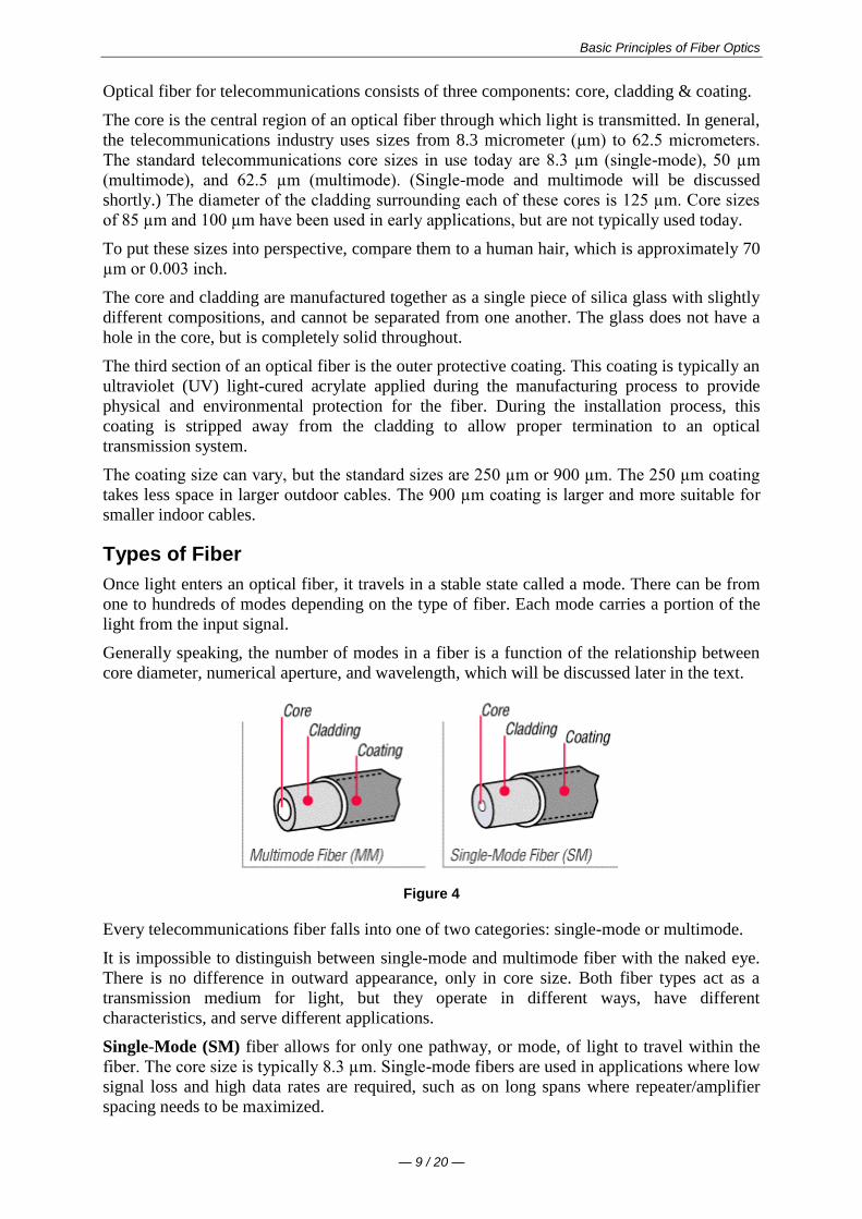
Basic Principles of Fiber Optics
mdash 9 20 mdash
Optical fiber for telecommunications consists of three components core cladding amp coating
The core is the central region of an optical fiber through which light is transmitted In general
the telecommunications industry uses sizes from 83 micrometer (microm) to 625 micrometers
The standard telecommunications core sizes in use today are 83 microm (single-mode) 50 microm
(multimode) and 625 microm (multimode) (Single-mode and multimode will be discussed
shortly) The diameter of the cladding surrounding each of these cores is 125 microm Core sizes
of 85 microm and 100 microm have been used in early applications but are not typically used today
To put these sizes into perspective compare them to a human hair which is approximately 70
microm or 0003 inch
The core and cladding are manufactured together as a single piece of silica glass with slightly
different compositions and cannot be separated from one another The glass does not have a
hole in the core but is completely solid throughout
The third section of an optical fiber is the outer protective coating This coating is typically an
ultraviolet (UV) light-cured acrylate applied during the manufacturing process to provide
physical and environmental protection for the fiber During the installation process this
coating is stripped away from the cladding to allow proper termination to an optical
transmission system
The coating size can vary but the standard sizes are 250 microm or 900 microm The 250 microm coating
takes less space in larger outdoor cables The 900 microm coating is larger and more suitable for
smaller indoor cables
Types of Fiber
Once light enters an optical fiber it travels in a stable state called a mode There can be from
one to hundreds of modes depending on the type of fiber Each mode carries a portion of the
light from the input signal
Generally speaking the number of modes in a fiber is a function of the relationship between
core diameter numerical aperture and wavelength which will be discussed later in the text
Figure 4
Every telecommunications fiber falls into one of two categories single-mode or multimode
It is impossible to distinguish between single-mode and multimode fiber with the naked eye
There is no difference in outward appearance only in core size Both fiber types act as a
transmission medium for light but they operate in different ways have different
characteristics and serve different applications
Single-Mode (SM) fiber allows for only one pathway or mode of light to travel within the
fiber The core size is typically 83 microm Single-mode fibers are used in applications where low
signal loss and high data rates are required such as on long spans where repeateramplifier
spacing needs to be maximized
Basic Principles of Fiber Optics
mdash 10 20 mdash
Multimode (MM) fiber allows more than one mode of light Common MM core sizes are 50
microm and 625 microm Multimode fiber is better suited for shorter distance applications Where
costly electronics are heavily concentrated the primary cost of the system does not lie with
the cable In such a case MM fiber is more economical because it can be used with
inexpensive connectors and LED transmitters making the total system cost lower This makes
MM fiber the ideal choice for short distance lower bandwidth applications
Check Your Understanding
Would you like to see how much youve learned
1 What purpose does the core of an optical fiber serve
It protects the fiber from the environment
It carries light through the fiber
It separates the cladding and the coating
2 Which of the following is NOT true of single-mode fiber
It carries more information than multimode fiber
Its core is smaller than multimode fiber
It is hollow in the center
3 At installation which of the following is NOT true about optical fiber
The cladding and coating are stripped away
The fiber has the ability to carry either analog or digital signals
Light signals must enter the fiber within the acceptance cone to propagate
Applied Principles of Operation
Index of Refraction (IOR)
The index of refraction (IOR) is a way of measuring the speed of light in a material Light
travels fastest in a vacuum such as outer space The actual speed of light in a vacuum is
300000 kilometers per second or 186000 miles per second
Index of Refraction is calculated by dividing the speed of light in a vacuum by the speed of
light in some other medium
The Index of Refraction of a vacuum by definition has a value of 1
For the sake of simplicity typical values are provided here in Figure 5 Notice that the typical
value for the cladding of an optical fiber is 146 The core value is 148 The larger the index
of refraction the more slowly light travels in that medium
Figure 5
Basic Principles of Fiber Optics
mdash 11 20 mdash
Total Internal Refraction
When a light ray traveling in one material hits a different material and reflects back into the
original material without any loss of light total internal refraction occurs
Since the core and cladding are constructed from different compositions of glass
theoretically light entering the core is confined to the boundaries of the core because it
reflects back whenever it hits the cladding For total internal reflection to occur the index of
refraction of the core must be higher than that of the cladding
Acceptance Cone
As mentioned earlier electrical signals are converted to light signals before they enter an
optical fiber To ensure that the signals reflect and travel correctly through the core the light
must enter the core through an imaginary acceptance cone (See Figure 7 below) The size of
this acceptance cone is a function of the refractive index difference between the core and the
cladding
In simpler terms there is a maximum angle from the fiber axis at which light may enter the
fiber so that it will propagate or travel in the core of the fiber The sine of this maximum
angle is the numerical aperture (NA) of the fiber Fiber with a larger NA requires less
precision to splice and work with than fiber with a smaller NA Single-mode fiber has a small
NA
Check Your Understanding
Would you like to see how much youve learned
1 Which of the following is true of the index of refraction
It is a way of measuring the speed of light in a material
It is calculated by dividing the speed of light in some medium by the speed of light
in a vacuum
When calculated it shows that the fastest light speed occurs in air
2 Total internal reflection is
Reflection that occurs when a light ray traveling in one material hits another
material and reflects back into the original material without any loss of light
Basic Principles of Fiber Optics
mdash 12 20 mdash
Complete meditation without interruption
Reflection that occurs when the refractive index of the core is lower than the
cladding
Optical Fiber Parameters
As with any type of transmission system there are certain parameters that affect the systems
operation
Wavelength
Light that can be seen by the unaided human eye is said to be in the visible spectrum In the
visible spectrum wavelength can be described as the color of light
To put this into perspective take a look at Figure 8 Notice that the colors of the rainbow -
red orange yellow green blue (indigo not shown) and violet fall within the visible
spectrum
Figure 8
Basic Principles of Fiber Optics
mdash 13 20 mdash
Optical fiber transmission uses wavelengths which are above the visible light spectrum and
thus undetectable to the unaided eye Typical optical transmission wavelengths are 850
nanometers (nm) 1310 nm and 1550 nm
Both lasers and LEDs (light-emitting diodes) are used to transmit light through optical fiber
Lasers are usually used for 1310 or 1550 nanometer single-mode applications LEDs are
used for 850 or 1300 nanometer multimode applications
Safety note Never look into the end of a fiber which may have a laser coupled to it Laser
light is invisible and can damage the eyes Viewing it directly does not cause pain The iris of
the eye will not close involuntarily as when viewing a bright light consequently serious
damage to the retina of the eye is possible Should accidental exposure to laser light be
suspected an eye examination should be arranged immediately
Window
There are ranges of wavelengths at which the fiber operates best Each range is known as an
operating window Each window is centered around the typical operational wavelength
Figure 9
These wavelengths were chosen because they best match the transmission properties of
available light sources with the transmission qualities of optical fiber
Frequency
The frequency of a system is the speed of modulation of the digital or analog output of the
light source in other words the number of pulses per second emitted from the light source
Frequency is measured in units of hertz (Hz) where 1 hertz is equal to 1 pulse or cycle per
second (Figure 10) A more practical measurement for optical communications is megahertz
(MHz) or millions of pulses per second
Figure 10
Attenuation
Attenuation is the loss of optical power as light travels down a fiber It is measured in decibels
(dBkm) Over a set distance a fiber with a lower attenuation will allow more power to reach
its receiver than a fiber with higher attenuation
Basic Principles of Fiber Optics
mdash 14 20 mdash
While low-loss optical systems are always desirable it is possible to lose a large portion of
the initial signal power without significant problems A loss of 50 of initial power is equal
to a 30 dB loss Any time fibers are joined together there will be some loss Losses for fusion
splicing and for mechanical splicing are typically 02 dB or less
Attenuation can be caused by several factors but is generally placed in one of two categories
intrinsic or extrinsic
Intrinsic Attenuation
Intrinsic attenuation occurs due to something inside or inherent to the fiber It is caused by
impurities in the glass during the manufacturing process As precise as manufacturing is there
is no way to eliminate all impurities though technological advances have caused attenuation
to decrease dramatically since the first optical fiber in 1970
When a light signal hits an impurity in the fiber one of two things will occur it will scatter or
it will be absorbed
Scattering
Rayleigh scattering accounts for the majority (about 96) of attenuation in optical fiber
Light travels in the core and interacts with the atoms in the glass The light waves elastically
collide with the atoms and light is scattered as a result
Rayleigh scattering is the result of these elastic collisions between the light wave and the
atoms in the fiber If the scattered light maintains an angle that supports forward travel within
the core no attenuation occurs If the light is scattered at an angle that does not support
continued forward travel the light is diverted out of the core and attenuation occurs
Figure 11
Some scattered light is reflected back toward the light source (input end) This is a property
that is used in an Optical Time Domain Reflectometer (OTDR) to test fibers This same
principle applies to analyzing loss associated with localized events in the fiber such as
splices
Absorption
The second type of intrinsic attenuation in fiber is absorption Absorption accounts for 3-5
of fiber attenuation This phenomenon causes a light signal to be absorbed by natural
impurities in the glass and converted to vibrational energy or some other form of energy
(Figure 12)
Unlike scattering absorption can be limited by controlling the amount of impurities during
the manufacturing process
Basic Principles of Fiber Optics
mdash 15 20 mdash
Figure 12
Extrinsic Attenuation
The second category of attenuation is extrinsic attenuation Extrinsic attenuation can be
caused by two external mechanisms macrobending or microbending Both cause a reduction
of optical power
Macrobending
If a bend is imposed on an optical fiber strain is placed on the fiber along the region that is
bent The bending strain will affect the refractive index and the critical angle of the light ray
in that specific area As a result light traveling in the core can refract out and loss occurs
(Figure 13)
A macrobend is a large-scale bend that is visible for example a fiber wrapped around a
persons finger This loss is generally reversible once bends are corrected
To prevent macrobends all optical fiber (and optical fiber cable) has a minimum bend radius
specification that should not be exceeded This is a restriction on how much bend a fiber can
withstand before experiencing problems in optical performance or mechanical reliability The
rule of thumb for minimum bend radius is 1 12 for bare single-mode fiber 10 times the
cables outside diameter (OD) for non-armored cable and 15 times the cables OD for
armored cable
Figure 13
Microbending
The second extrinsic cause of attenuation is a microbend This is a small-scale distortion
generally indicative of pressure on the fiber (See Figure 14 below) Microbending may be
related to temperature tensile stress or crushing force Like macrobending microbending
will cause a reduction of optical power in the glass
Microbending is very localized and the bend may not be clearly visible upon inspection With
bare fiber microbending may be reversible in the cabling process it may not
Basic Principles of Fiber Optics
mdash 16 20 mdash
Figure 14
Dispersion
Dispersion is the spreading of a light pulse as it travels down a fiber (See Figure 15) As
the pulses spread or broaden they tend to overlap and are no longer distinguishable by the
receiver as 0s and 1s Light pulses launched close together (high data rates) that spread too
much (high dispersion) result in errors and loss of information
Chromatic dispersion occurs as a result of the range of wavelengths in the light source Light
from lasers and LEDs consists of a range of wavelengths Each of these wavelengths travels at
a slightly different speed Over distance the varying wavelength speeds cause the light pulse
to spread in time This is of most importance in single-mode applications
Modal dispersion is significant in multimode applications where the various modes of light
traveling down the fiber arrive at the receiver at different times causing a spreading effect
Figure 15
Pulse width is measured at full width-half maximum in other words the full width of the
pulse at half the maximum pulse height Dispersion limits how fast or how much
information can be sent over an optical fiber
There are other effects of dispersion but further discussion is beyond the scope of this text
For more in-depth reading please consult the bibliography at the end of this publication
Bandwidth
In simplest terms bandwidth is the amount of information a fiber can carry so that every pulse
is distinguishable by the receiver at the end (Figure 16)
Basic Principles of Fiber Optics
mdash 17 20 mdash
Figure 16
As discussed in the previous section dispersion causes light pulses to spread The spreading
of these light pulses causes them to merge together At a certain distance and frequency the
pulses become unreadable by the receiver The multiple pathways of a multimode fiber cause
this overlap to be much greater than for single-mode fiber These different paths have
different lengths which cause each mode of light to arrive at a different time
System bandwidth is measured in megahertz (MHz) at one km In general when a systems
bandwidth is 200 MHzmiddotkm it means that 200 million pulses of light per second will travel
down 1 km (1000 meters) of fiber and each pulse will be distinguishable by the receiver
Check Your Understanding
Would you like to see how much youve learned
1 In optical fiber systems what are the typical wavelengths of operation
400 nm 455 nm 490 nm
620 nm 750 nm 800 nm
850 nm 1310 nm 1550 nm
2 What is an optical window
A glass object on the side of a building
A range of wavelengths at which fiber best operates
The moment in time when fiber became a commercially-viable enterprise
3 Which of the following is not true of attenuation
It is the loss of optical power as light travels down a fiber
It may be induced by scattering absorbing macrobending and microbending
It is measured in nanometers
4 What is bandwidth
A measure of the information-carrying capacity of an optical fiber
The side-to-side measurement of a wedding ring
A term used to express the total loss of an optical system
Fiber Manufacturing
There are several ways to manufacture optical fiber but this text will concentrate on the
method developed patented and used by the former Corning Glass Works now Corning
Incorporated
This method called Outside Vapor Deposition or OVD has three steps or phases laydown
consolidation and draw
Basic Principles of Fiber Optics
mdash 18 20 mdash
Laydown
In the laydown step a soot preform is made from ultrapure vapors of silicon tetrachloride and
germanium tetrachloride The vapors travel through a traversing burner and react in the flame
to form soot particles of silica and germania
Figure 17
The OVD process is distinguished by the method of depositing the soot These particles are
deposited on the surface of a rotating target rod The core material is deposited first followed
by the pure silica cladding Since both core and cladding raw materials are vapor-deposited
the entire preform is extremely pure
Consolidation
When deposition is complete the target rod is removed from the center of the porous preform
and the preform is placed into a consolidation furnace During the consolidation process the
water vapor is removed from the preform This high-temperature consolidation step sinters the
preform into a solid dense transparent glass blank The hole left by the target rod is fused
solid by the extremely high temperature of the draw furnace
Draw
The finished glass preform is placed in a draw tower and drawn into a continuous strand of
glass fiber First the blank is lowered into the top of the draw furnace
Basic Principles of Fiber Optics
mdash 19 20 mdash
Figure 18
The tip of the blank is heated until a piece of molten glass called a gob begins to fall from
the blank like hot taffy It pulls a thin strand of glass the beginning of an optical fiber
The fiber goes through a precise on-line diameter monitor to ensure specified outside
diameter Next coatings are applied and cured using ultraviolet lamps
At the bottom of the draw the fiber is wound on spools Each fiber is assigned a unique
identification number that encodes all relevant manufacturing data including raw materials
and manufacturing equipment
Note Extensive text and graphics in this Fiber Manufacturing section are used with
permission of Corning Communications
Check Your Understanding
Would you like to see how much youve learned
1 What are the three steps of fiber manufacture using the Outside Vapor Deposition (OVD)
method
Burner vapor fuel
Laydown consolidation draw
Gas glass spool
2 Which of the following is NOT true about the laydown stage of OVD fiber manufacture
A rotating target rod collects soot deposited from the burner
Basic Principles of Fiber Optics
mdash 20 20 mdash
The soot forms a preform
The preform is highly impure until it reaches the consolidation phase
3 Which of the following is NOT true about the consolidation stage of fiber manufacture
The removal of the target rod causes the core of the fiber to be hollow
Water vapor is removed from the preform
The white preform becomes a solid dense transparent glass blank
4 Which of the following is NOT true about the draw stage of fiber manufacture
The glass preform is drawn into a continuous piece of glass fiber
Fiber diameters are measured on-line
Coatings are applied and cured using infrared lamps
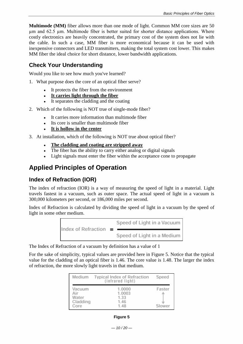
Basic Principles of Fiber Optics
mdash 10 20 mdash
Multimode (MM) fiber allows more than one mode of light Common MM core sizes are 50
microm and 625 microm Multimode fiber is better suited for shorter distance applications Where
costly electronics are heavily concentrated the primary cost of the system does not lie with
the cable In such a case MM fiber is more economical because it can be used with
inexpensive connectors and LED transmitters making the total system cost lower This makes
MM fiber the ideal choice for short distance lower bandwidth applications
Check Your Understanding
Would you like to see how much youve learned
1 What purpose does the core of an optical fiber serve
It protects the fiber from the environment
It carries light through the fiber
It separates the cladding and the coating
2 Which of the following is NOT true of single-mode fiber
It carries more information than multimode fiber
Its core is smaller than multimode fiber
It is hollow in the center
3 At installation which of the following is NOT true about optical fiber
The cladding and coating are stripped away
The fiber has the ability to carry either analog or digital signals
Light signals must enter the fiber within the acceptance cone to propagate
Applied Principles of Operation
Index of Refraction (IOR)
The index of refraction (IOR) is a way of measuring the speed of light in a material Light
travels fastest in a vacuum such as outer space The actual speed of light in a vacuum is
300000 kilometers per second or 186000 miles per second
Index of Refraction is calculated by dividing the speed of light in a vacuum by the speed of
light in some other medium
The Index of Refraction of a vacuum by definition has a value of 1
For the sake of simplicity typical values are provided here in Figure 5 Notice that the typical
value for the cladding of an optical fiber is 146 The core value is 148 The larger the index
of refraction the more slowly light travels in that medium
Figure 5
Basic Principles of Fiber Optics
mdash 11 20 mdash
Total Internal Refraction
When a light ray traveling in one material hits a different material and reflects back into the
original material without any loss of light total internal refraction occurs
Since the core and cladding are constructed from different compositions of glass
theoretically light entering the core is confined to the boundaries of the core because it
reflects back whenever it hits the cladding For total internal reflection to occur the index of
refraction of the core must be higher than that of the cladding
Acceptance Cone
As mentioned earlier electrical signals are converted to light signals before they enter an
optical fiber To ensure that the signals reflect and travel correctly through the core the light
must enter the core through an imaginary acceptance cone (See Figure 7 below) The size of
this acceptance cone is a function of the refractive index difference between the core and the
cladding
In simpler terms there is a maximum angle from the fiber axis at which light may enter the
fiber so that it will propagate or travel in the core of the fiber The sine of this maximum
angle is the numerical aperture (NA) of the fiber Fiber with a larger NA requires less
precision to splice and work with than fiber with a smaller NA Single-mode fiber has a small
NA
Check Your Understanding
Would you like to see how much youve learned
1 Which of the following is true of the index of refraction
It is a way of measuring the speed of light in a material
It is calculated by dividing the speed of light in some medium by the speed of light
in a vacuum
When calculated it shows that the fastest light speed occurs in air
2 Total internal reflection is
Reflection that occurs when a light ray traveling in one material hits another
material and reflects back into the original material without any loss of light
Basic Principles of Fiber Optics
mdash 12 20 mdash
Complete meditation without interruption
Reflection that occurs when the refractive index of the core is lower than the
cladding
Optical Fiber Parameters
As with any type of transmission system there are certain parameters that affect the systems
operation
Wavelength
Light that can be seen by the unaided human eye is said to be in the visible spectrum In the
visible spectrum wavelength can be described as the color of light
To put this into perspective take a look at Figure 8 Notice that the colors of the rainbow -
red orange yellow green blue (indigo not shown) and violet fall within the visible
spectrum
Figure 8
Basic Principles of Fiber Optics
mdash 13 20 mdash
Optical fiber transmission uses wavelengths which are above the visible light spectrum and
thus undetectable to the unaided eye Typical optical transmission wavelengths are 850
nanometers (nm) 1310 nm and 1550 nm
Both lasers and LEDs (light-emitting diodes) are used to transmit light through optical fiber
Lasers are usually used for 1310 or 1550 nanometer single-mode applications LEDs are
used for 850 or 1300 nanometer multimode applications
Safety note Never look into the end of a fiber which may have a laser coupled to it Laser
light is invisible and can damage the eyes Viewing it directly does not cause pain The iris of
the eye will not close involuntarily as when viewing a bright light consequently serious
damage to the retina of the eye is possible Should accidental exposure to laser light be
suspected an eye examination should be arranged immediately
Window
There are ranges of wavelengths at which the fiber operates best Each range is known as an
operating window Each window is centered around the typical operational wavelength
Figure 9
These wavelengths were chosen because they best match the transmission properties of
available light sources with the transmission qualities of optical fiber
Frequency
The frequency of a system is the speed of modulation of the digital or analog output of the
light source in other words the number of pulses per second emitted from the light source
Frequency is measured in units of hertz (Hz) where 1 hertz is equal to 1 pulse or cycle per
second (Figure 10) A more practical measurement for optical communications is megahertz
(MHz) or millions of pulses per second
Figure 10
Attenuation
Attenuation is the loss of optical power as light travels down a fiber It is measured in decibels
(dBkm) Over a set distance a fiber with a lower attenuation will allow more power to reach
its receiver than a fiber with higher attenuation
Basic Principles of Fiber Optics
mdash 14 20 mdash
While low-loss optical systems are always desirable it is possible to lose a large portion of
the initial signal power without significant problems A loss of 50 of initial power is equal
to a 30 dB loss Any time fibers are joined together there will be some loss Losses for fusion
splicing and for mechanical splicing are typically 02 dB or less
Attenuation can be caused by several factors but is generally placed in one of two categories
intrinsic or extrinsic
Intrinsic Attenuation
Intrinsic attenuation occurs due to something inside or inherent to the fiber It is caused by
impurities in the glass during the manufacturing process As precise as manufacturing is there
is no way to eliminate all impurities though technological advances have caused attenuation
to decrease dramatically since the first optical fiber in 1970
When a light signal hits an impurity in the fiber one of two things will occur it will scatter or
it will be absorbed
Scattering
Rayleigh scattering accounts for the majority (about 96) of attenuation in optical fiber
Light travels in the core and interacts with the atoms in the glass The light waves elastically
collide with the atoms and light is scattered as a result
Rayleigh scattering is the result of these elastic collisions between the light wave and the
atoms in the fiber If the scattered light maintains an angle that supports forward travel within
the core no attenuation occurs If the light is scattered at an angle that does not support
continued forward travel the light is diverted out of the core and attenuation occurs
Figure 11
Some scattered light is reflected back toward the light source (input end) This is a property
that is used in an Optical Time Domain Reflectometer (OTDR) to test fibers This same
principle applies to analyzing loss associated with localized events in the fiber such as
splices
Absorption
The second type of intrinsic attenuation in fiber is absorption Absorption accounts for 3-5
of fiber attenuation This phenomenon causes a light signal to be absorbed by natural
impurities in the glass and converted to vibrational energy or some other form of energy
(Figure 12)
Unlike scattering absorption can be limited by controlling the amount of impurities during
the manufacturing process
Basic Principles of Fiber Optics
mdash 15 20 mdash
Figure 12
Extrinsic Attenuation
The second category of attenuation is extrinsic attenuation Extrinsic attenuation can be
caused by two external mechanisms macrobending or microbending Both cause a reduction
of optical power
Macrobending
If a bend is imposed on an optical fiber strain is placed on the fiber along the region that is
bent The bending strain will affect the refractive index and the critical angle of the light ray
in that specific area As a result light traveling in the core can refract out and loss occurs
(Figure 13)
A macrobend is a large-scale bend that is visible for example a fiber wrapped around a
persons finger This loss is generally reversible once bends are corrected
To prevent macrobends all optical fiber (and optical fiber cable) has a minimum bend radius
specification that should not be exceeded This is a restriction on how much bend a fiber can
withstand before experiencing problems in optical performance or mechanical reliability The
rule of thumb for minimum bend radius is 1 12 for bare single-mode fiber 10 times the
cables outside diameter (OD) for non-armored cable and 15 times the cables OD for
armored cable
Figure 13
Microbending
The second extrinsic cause of attenuation is a microbend This is a small-scale distortion
generally indicative of pressure on the fiber (See Figure 14 below) Microbending may be
related to temperature tensile stress or crushing force Like macrobending microbending
will cause a reduction of optical power in the glass
Microbending is very localized and the bend may not be clearly visible upon inspection With
bare fiber microbending may be reversible in the cabling process it may not
Basic Principles of Fiber Optics
mdash 16 20 mdash
Figure 14
Dispersion
Dispersion is the spreading of a light pulse as it travels down a fiber (See Figure 15) As
the pulses spread or broaden they tend to overlap and are no longer distinguishable by the
receiver as 0s and 1s Light pulses launched close together (high data rates) that spread too
much (high dispersion) result in errors and loss of information
Chromatic dispersion occurs as a result of the range of wavelengths in the light source Light
from lasers and LEDs consists of a range of wavelengths Each of these wavelengths travels at
a slightly different speed Over distance the varying wavelength speeds cause the light pulse
to spread in time This is of most importance in single-mode applications
Modal dispersion is significant in multimode applications where the various modes of light
traveling down the fiber arrive at the receiver at different times causing a spreading effect
Figure 15
Pulse width is measured at full width-half maximum in other words the full width of the
pulse at half the maximum pulse height Dispersion limits how fast or how much
information can be sent over an optical fiber
There are other effects of dispersion but further discussion is beyond the scope of this text
For more in-depth reading please consult the bibliography at the end of this publication
Bandwidth
In simplest terms bandwidth is the amount of information a fiber can carry so that every pulse
is distinguishable by the receiver at the end (Figure 16)
Basic Principles of Fiber Optics
mdash 17 20 mdash
Figure 16
As discussed in the previous section dispersion causes light pulses to spread The spreading
of these light pulses causes them to merge together At a certain distance and frequency the
pulses become unreadable by the receiver The multiple pathways of a multimode fiber cause
this overlap to be much greater than for single-mode fiber These different paths have
different lengths which cause each mode of light to arrive at a different time
System bandwidth is measured in megahertz (MHz) at one km In general when a systems
bandwidth is 200 MHzmiddotkm it means that 200 million pulses of light per second will travel
down 1 km (1000 meters) of fiber and each pulse will be distinguishable by the receiver
Check Your Understanding
Would you like to see how much youve learned
1 In optical fiber systems what are the typical wavelengths of operation
400 nm 455 nm 490 nm
620 nm 750 nm 800 nm
850 nm 1310 nm 1550 nm
2 What is an optical window
A glass object on the side of a building
A range of wavelengths at which fiber best operates
The moment in time when fiber became a commercially-viable enterprise
3 Which of the following is not true of attenuation
It is the loss of optical power as light travels down a fiber
It may be induced by scattering absorbing macrobending and microbending
It is measured in nanometers
4 What is bandwidth
A measure of the information-carrying capacity of an optical fiber
The side-to-side measurement of a wedding ring
A term used to express the total loss of an optical system
Fiber Manufacturing
There are several ways to manufacture optical fiber but this text will concentrate on the
method developed patented and used by the former Corning Glass Works now Corning
Incorporated
This method called Outside Vapor Deposition or OVD has three steps or phases laydown
consolidation and draw
Basic Principles of Fiber Optics
mdash 18 20 mdash
Laydown
In the laydown step a soot preform is made from ultrapure vapors of silicon tetrachloride and
germanium tetrachloride The vapors travel through a traversing burner and react in the flame
to form soot particles of silica and germania
Figure 17
The OVD process is distinguished by the method of depositing the soot These particles are
deposited on the surface of a rotating target rod The core material is deposited first followed
by the pure silica cladding Since both core and cladding raw materials are vapor-deposited
the entire preform is extremely pure
Consolidation
When deposition is complete the target rod is removed from the center of the porous preform
and the preform is placed into a consolidation furnace During the consolidation process the
water vapor is removed from the preform This high-temperature consolidation step sinters the
preform into a solid dense transparent glass blank The hole left by the target rod is fused
solid by the extremely high temperature of the draw furnace
Draw
The finished glass preform is placed in a draw tower and drawn into a continuous strand of
glass fiber First the blank is lowered into the top of the draw furnace
Basic Principles of Fiber Optics
mdash 19 20 mdash
Figure 18
The tip of the blank is heated until a piece of molten glass called a gob begins to fall from
the blank like hot taffy It pulls a thin strand of glass the beginning of an optical fiber
The fiber goes through a precise on-line diameter monitor to ensure specified outside
diameter Next coatings are applied and cured using ultraviolet lamps
At the bottom of the draw the fiber is wound on spools Each fiber is assigned a unique
identification number that encodes all relevant manufacturing data including raw materials
and manufacturing equipment
Note Extensive text and graphics in this Fiber Manufacturing section are used with
permission of Corning Communications
Check Your Understanding
Would you like to see how much youve learned
1 What are the three steps of fiber manufacture using the Outside Vapor Deposition (OVD)
method
Burner vapor fuel
Laydown consolidation draw
Gas glass spool
2 Which of the following is NOT true about the laydown stage of OVD fiber manufacture
A rotating target rod collects soot deposited from the burner
Basic Principles of Fiber Optics
mdash 20 20 mdash
The soot forms a preform
The preform is highly impure until it reaches the consolidation phase
3 Which of the following is NOT true about the consolidation stage of fiber manufacture
The removal of the target rod causes the core of the fiber to be hollow
Water vapor is removed from the preform
The white preform becomes a solid dense transparent glass blank
4 Which of the following is NOT true about the draw stage of fiber manufacture
The glass preform is drawn into a continuous piece of glass fiber
Fiber diameters are measured on-line
Coatings are applied and cured using infrared lamps
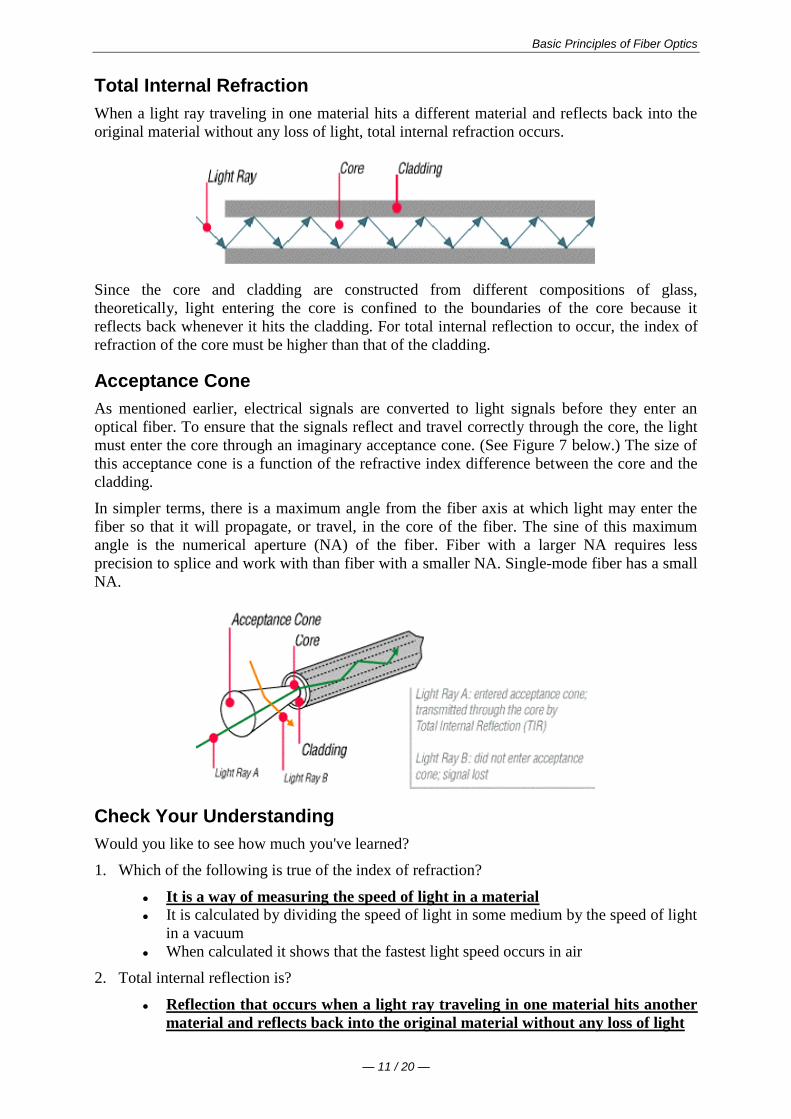
Basic Principles of Fiber Optics
mdash 12 20 mdash
Complete meditation without interruption
Reflection that occurs when the refractive index of the core is lower than the
cladding
Optical Fiber Parameters
As with any type of transmission system there are certain parameters that affect the systems
operation
Wavelength
Light that can be seen by the unaided human eye is said to be in the visible spectrum In the
visible spectrum wavelength can be described as the color of light
To put this into perspective take a look at Figure 8 Notice that the colors of the rainbow -
red orange yellow green blue (indigo not shown) and violet fall within the visible
spectrum
Figure 8
Basic Principles of Fiber Optics
mdash 13 20 mdash
Optical fiber transmission uses wavelengths which are above the visible light spectrum and
thus undetectable to the unaided eye Typical optical transmission wavelengths are 850
nanometers (nm) 1310 nm and 1550 nm
Both lasers and LEDs (light-emitting diodes) are used to transmit light through optical fiber
Lasers are usually used for 1310 or 1550 nanometer single-mode applications LEDs are
used for 850 or 1300 nanometer multimode applications
Safety note Never look into the end of a fiber which may have a laser coupled to it Laser
light is invisible and can damage the eyes Viewing it directly does not cause pain The iris of
the eye will not close involuntarily as when viewing a bright light consequently serious
damage to the retina of the eye is possible Should accidental exposure to laser light be
suspected an eye examination should be arranged immediately
Window
There are ranges of wavelengths at which the fiber operates best Each range is known as an
operating window Each window is centered around the typical operational wavelength
Figure 9
These wavelengths were chosen because they best match the transmission properties of
available light sources with the transmission qualities of optical fiber
Frequency
The frequency of a system is the speed of modulation of the digital or analog output of the
light source in other words the number of pulses per second emitted from the light source
Frequency is measured in units of hertz (Hz) where 1 hertz is equal to 1 pulse or cycle per
second (Figure 10) A more practical measurement for optical communications is megahertz
(MHz) or millions of pulses per second
Figure 10
Attenuation
Attenuation is the loss of optical power as light travels down a fiber It is measured in decibels
(dBkm) Over a set distance a fiber with a lower attenuation will allow more power to reach
its receiver than a fiber with higher attenuation
Basic Principles of Fiber Optics
mdash 14 20 mdash
While low-loss optical systems are always desirable it is possible to lose a large portion of
the initial signal power without significant problems A loss of 50 of initial power is equal
to a 30 dB loss Any time fibers are joined together there will be some loss Losses for fusion
splicing and for mechanical splicing are typically 02 dB or less
Attenuation can be caused by several factors but is generally placed in one of two categories
intrinsic or extrinsic
Intrinsic Attenuation
Intrinsic attenuation occurs due to something inside or inherent to the fiber It is caused by
impurities in the glass during the manufacturing process As precise as manufacturing is there
is no way to eliminate all impurities though technological advances have caused attenuation
to decrease dramatically since the first optical fiber in 1970
When a light signal hits an impurity in the fiber one of two things will occur it will scatter or
it will be absorbed
Scattering
Rayleigh scattering accounts for the majority (about 96) of attenuation in optical fiber
Light travels in the core and interacts with the atoms in the glass The light waves elastically
collide with the atoms and light is scattered as a result
Rayleigh scattering is the result of these elastic collisions between the light wave and the
atoms in the fiber If the scattered light maintains an angle that supports forward travel within
the core no attenuation occurs If the light is scattered at an angle that does not support
continued forward travel the light is diverted out of the core and attenuation occurs
Figure 11
Some scattered light is reflected back toward the light source (input end) This is a property
that is used in an Optical Time Domain Reflectometer (OTDR) to test fibers This same
principle applies to analyzing loss associated with localized events in the fiber such as
splices
Absorption
The second type of intrinsic attenuation in fiber is absorption Absorption accounts for 3-5
of fiber attenuation This phenomenon causes a light signal to be absorbed by natural
impurities in the glass and converted to vibrational energy or some other form of energy
(Figure 12)
Unlike scattering absorption can be limited by controlling the amount of impurities during
the manufacturing process
Basic Principles of Fiber Optics
mdash 15 20 mdash
Figure 12
Extrinsic Attenuation
The second category of attenuation is extrinsic attenuation Extrinsic attenuation can be
caused by two external mechanisms macrobending or microbending Both cause a reduction
of optical power
Macrobending
If a bend is imposed on an optical fiber strain is placed on the fiber along the region that is
bent The bending strain will affect the refractive index and the critical angle of the light ray
in that specific area As a result light traveling in the core can refract out and loss occurs
(Figure 13)
A macrobend is a large-scale bend that is visible for example a fiber wrapped around a
persons finger This loss is generally reversible once bends are corrected
To prevent macrobends all optical fiber (and optical fiber cable) has a minimum bend radius
specification that should not be exceeded This is a restriction on how much bend a fiber can
withstand before experiencing problems in optical performance or mechanical reliability The
rule of thumb for minimum bend radius is 1 12 for bare single-mode fiber 10 times the
cables outside diameter (OD) for non-armored cable and 15 times the cables OD for
armored cable
Figure 13
Microbending
The second extrinsic cause of attenuation is a microbend This is a small-scale distortion
generally indicative of pressure on the fiber (See Figure 14 below) Microbending may be
related to temperature tensile stress or crushing force Like macrobending microbending
will cause a reduction of optical power in the glass
Microbending is very localized and the bend may not be clearly visible upon inspection With
bare fiber microbending may be reversible in the cabling process it may not
Basic Principles of Fiber Optics
mdash 16 20 mdash
Figure 14
Dispersion
Dispersion is the spreading of a light pulse as it travels down a fiber (See Figure 15) As
the pulses spread or broaden they tend to overlap and are no longer distinguishable by the
receiver as 0s and 1s Light pulses launched close together (high data rates) that spread too
much (high dispersion) result in errors and loss of information
Chromatic dispersion occurs as a result of the range of wavelengths in the light source Light
from lasers and LEDs consists of a range of wavelengths Each of these wavelengths travels at
a slightly different speed Over distance the varying wavelength speeds cause the light pulse
to spread in time This is of most importance in single-mode applications
Modal dispersion is significant in multimode applications where the various modes of light
traveling down the fiber arrive at the receiver at different times causing a spreading effect
Figure 15
Pulse width is measured at full width-half maximum in other words the full width of the
pulse at half the maximum pulse height Dispersion limits how fast or how much
information can be sent over an optical fiber
There are other effects of dispersion but further discussion is beyond the scope of this text
For more in-depth reading please consult the bibliography at the end of this publication
Bandwidth
In simplest terms bandwidth is the amount of information a fiber can carry so that every pulse
is distinguishable by the receiver at the end (Figure 16)
Basic Principles of Fiber Optics
mdash 17 20 mdash
Figure 16
As discussed in the previous section dispersion causes light pulses to spread The spreading
of these light pulses causes them to merge together At a certain distance and frequency the
pulses become unreadable by the receiver The multiple pathways of a multimode fiber cause
this overlap to be much greater than for single-mode fiber These different paths have
different lengths which cause each mode of light to arrive at a different time
System bandwidth is measured in megahertz (MHz) at one km In general when a systems
bandwidth is 200 MHzmiddotkm it means that 200 million pulses of light per second will travel
down 1 km (1000 meters) of fiber and each pulse will be distinguishable by the receiver
Check Your Understanding
Would you like to see how much youve learned
1 In optical fiber systems what are the typical wavelengths of operation
400 nm 455 nm 490 nm
620 nm 750 nm 800 nm
850 nm 1310 nm 1550 nm
2 What is an optical window
A glass object on the side of a building
A range of wavelengths at which fiber best operates
The moment in time when fiber became a commercially-viable enterprise
3 Which of the following is not true of attenuation
It is the loss of optical power as light travels down a fiber
It may be induced by scattering absorbing macrobending and microbending
It is measured in nanometers
4 What is bandwidth
A measure of the information-carrying capacity of an optical fiber
The side-to-side measurement of a wedding ring
A term used to express the total loss of an optical system
Fiber Manufacturing
There are several ways to manufacture optical fiber but this text will concentrate on the
method developed patented and used by the former Corning Glass Works now Corning
Incorporated
This method called Outside Vapor Deposition or OVD has three steps or phases laydown
consolidation and draw
Basic Principles of Fiber Optics
mdash 18 20 mdash
Laydown
In the laydown step a soot preform is made from ultrapure vapors of silicon tetrachloride and
germanium tetrachloride The vapors travel through a traversing burner and react in the flame
to form soot particles of silica and germania
Figure 17
The OVD process is distinguished by the method of depositing the soot These particles are
deposited on the surface of a rotating target rod The core material is deposited first followed
by the pure silica cladding Since both core and cladding raw materials are vapor-deposited
the entire preform is extremely pure
Consolidation
When deposition is complete the target rod is removed from the center of the porous preform
and the preform is placed into a consolidation furnace During the consolidation process the
water vapor is removed from the preform This high-temperature consolidation step sinters the
preform into a solid dense transparent glass blank The hole left by the target rod is fused
solid by the extremely high temperature of the draw furnace
Draw
The finished glass preform is placed in a draw tower and drawn into a continuous strand of
glass fiber First the blank is lowered into the top of the draw furnace
Basic Principles of Fiber Optics
mdash 19 20 mdash
Figure 18
The tip of the blank is heated until a piece of molten glass called a gob begins to fall from
the blank like hot taffy It pulls a thin strand of glass the beginning of an optical fiber
The fiber goes through a precise on-line diameter monitor to ensure specified outside
diameter Next coatings are applied and cured using ultraviolet lamps
At the bottom of the draw the fiber is wound on spools Each fiber is assigned a unique
identification number that encodes all relevant manufacturing data including raw materials
and manufacturing equipment
Note Extensive text and graphics in this Fiber Manufacturing section are used with
permission of Corning Communications
Check Your Understanding
Would you like to see how much youve learned
1 What are the three steps of fiber manufacture using the Outside Vapor Deposition (OVD)
method
Burner vapor fuel
Laydown consolidation draw
Gas glass spool
2 Which of the following is NOT true about the laydown stage of OVD fiber manufacture
A rotating target rod collects soot deposited from the burner
Basic Principles of Fiber Optics
mdash 20 20 mdash
The soot forms a preform
The preform is highly impure until it reaches the consolidation phase
3 Which of the following is NOT true about the consolidation stage of fiber manufacture
The removal of the target rod causes the core of the fiber to be hollow
Water vapor is removed from the preform
The white preform becomes a solid dense transparent glass blank
4 Which of the following is NOT true about the draw stage of fiber manufacture
The glass preform is drawn into a continuous piece of glass fiber
Fiber diameters are measured on-line
Coatings are applied and cured using infrared lamps
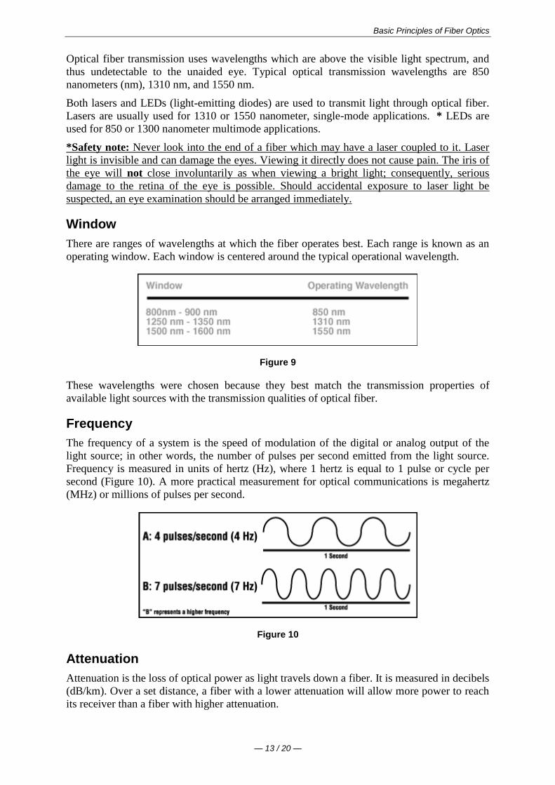
Basic Principles of Fiber Optics
mdash 13 20 mdash
Optical fiber transmission uses wavelengths which are above the visible light spectrum and
thus undetectable to the unaided eye Typical optical transmission wavelengths are 850
nanometers (nm) 1310 nm and 1550 nm
Both lasers and LEDs (light-emitting diodes) are used to transmit light through optical fiber
Lasers are usually used for 1310 or 1550 nanometer single-mode applications LEDs are
used for 850 or 1300 nanometer multimode applications
Safety note Never look into the end of a fiber which may have a laser coupled to it Laser
light is invisible and can damage the eyes Viewing it directly does not cause pain The iris of
the eye will not close involuntarily as when viewing a bright light consequently serious
damage to the retina of the eye is possible Should accidental exposure to laser light be
suspected an eye examination should be arranged immediately
Window
There are ranges of wavelengths at which the fiber operates best Each range is known as an
operating window Each window is centered around the typical operational wavelength
Figure 9
These wavelengths were chosen because they best match the transmission properties of
available light sources with the transmission qualities of optical fiber
Frequency
The frequency of a system is the speed of modulation of the digital or analog output of the
light source in other words the number of pulses per second emitted from the light source
Frequency is measured in units of hertz (Hz) where 1 hertz is equal to 1 pulse or cycle per
second (Figure 10) A more practical measurement for optical communications is megahertz
(MHz) or millions of pulses per second
Figure 10
Attenuation
Attenuation is the loss of optical power as light travels down a fiber It is measured in decibels
(dBkm) Over a set distance a fiber with a lower attenuation will allow more power to reach
its receiver than a fiber with higher attenuation
Basic Principles of Fiber Optics
mdash 14 20 mdash
While low-loss optical systems are always desirable it is possible to lose a large portion of
the initial signal power without significant problems A loss of 50 of initial power is equal
to a 30 dB loss Any time fibers are joined together there will be some loss Losses for fusion
splicing and for mechanical splicing are typically 02 dB or less
Attenuation can be caused by several factors but is generally placed in one of two categories
intrinsic or extrinsic
Intrinsic Attenuation
Intrinsic attenuation occurs due to something inside or inherent to the fiber It is caused by
impurities in the glass during the manufacturing process As precise as manufacturing is there
is no way to eliminate all impurities though technological advances have caused attenuation
to decrease dramatically since the first optical fiber in 1970
When a light signal hits an impurity in the fiber one of two things will occur it will scatter or
it will be absorbed
Scattering
Rayleigh scattering accounts for the majority (about 96) of attenuation in optical fiber
Light travels in the core and interacts with the atoms in the glass The light waves elastically
collide with the atoms and light is scattered as a result
Rayleigh scattering is the result of these elastic collisions between the light wave and the
atoms in the fiber If the scattered light maintains an angle that supports forward travel within
the core no attenuation occurs If the light is scattered at an angle that does not support
continued forward travel the light is diverted out of the core and attenuation occurs
Figure 11
Some scattered light is reflected back toward the light source (input end) This is a property
that is used in an Optical Time Domain Reflectometer (OTDR) to test fibers This same
principle applies to analyzing loss associated with localized events in the fiber such as
splices
Absorption
The second type of intrinsic attenuation in fiber is absorption Absorption accounts for 3-5
of fiber attenuation This phenomenon causes a light signal to be absorbed by natural
impurities in the glass and converted to vibrational energy or some other form of energy
(Figure 12)
Unlike scattering absorption can be limited by controlling the amount of impurities during
the manufacturing process
Basic Principles of Fiber Optics
mdash 15 20 mdash
Figure 12
Extrinsic Attenuation
The second category of attenuation is extrinsic attenuation Extrinsic attenuation can be
caused by two external mechanisms macrobending or microbending Both cause a reduction
of optical power
Macrobending
If a bend is imposed on an optical fiber strain is placed on the fiber along the region that is
bent The bending strain will affect the refractive index and the critical angle of the light ray
in that specific area As a result light traveling in the core can refract out and loss occurs
(Figure 13)
A macrobend is a large-scale bend that is visible for example a fiber wrapped around a
persons finger This loss is generally reversible once bends are corrected
To prevent macrobends all optical fiber (and optical fiber cable) has a minimum bend radius
specification that should not be exceeded This is a restriction on how much bend a fiber can
withstand before experiencing problems in optical performance or mechanical reliability The
rule of thumb for minimum bend radius is 1 12 for bare single-mode fiber 10 times the
cables outside diameter (OD) for non-armored cable and 15 times the cables OD for
armored cable
Figure 13
Microbending
The second extrinsic cause of attenuation is a microbend This is a small-scale distortion
generally indicative of pressure on the fiber (See Figure 14 below) Microbending may be
related to temperature tensile stress or crushing force Like macrobending microbending
will cause a reduction of optical power in the glass
Microbending is very localized and the bend may not be clearly visible upon inspection With
bare fiber microbending may be reversible in the cabling process it may not
Basic Principles of Fiber Optics
mdash 16 20 mdash
Figure 14
Dispersion
Dispersion is the spreading of a light pulse as it travels down a fiber (See Figure 15) As
the pulses spread or broaden they tend to overlap and are no longer distinguishable by the
receiver as 0s and 1s Light pulses launched close together (high data rates) that spread too
much (high dispersion) result in errors and loss of information
Chromatic dispersion occurs as a result of the range of wavelengths in the light source Light
from lasers and LEDs consists of a range of wavelengths Each of these wavelengths travels at
a slightly different speed Over distance the varying wavelength speeds cause the light pulse
to spread in time This is of most importance in single-mode applications
Modal dispersion is significant in multimode applications where the various modes of light
traveling down the fiber arrive at the receiver at different times causing a spreading effect
Figure 15
Pulse width is measured at full width-half maximum in other words the full width of the
pulse at half the maximum pulse height Dispersion limits how fast or how much
information can be sent over an optical fiber
There are other effects of dispersion but further discussion is beyond the scope of this text
For more in-depth reading please consult the bibliography at the end of this publication
Bandwidth
In simplest terms bandwidth is the amount of information a fiber can carry so that every pulse
is distinguishable by the receiver at the end (Figure 16)
Basic Principles of Fiber Optics
mdash 17 20 mdash
Figure 16
As discussed in the previous section dispersion causes light pulses to spread The spreading
of these light pulses causes them to merge together At a certain distance and frequency the
pulses become unreadable by the receiver The multiple pathways of a multimode fiber cause
this overlap to be much greater than for single-mode fiber These different paths have
different lengths which cause each mode of light to arrive at a different time
System bandwidth is measured in megahertz (MHz) at one km In general when a systems
bandwidth is 200 MHzmiddotkm it means that 200 million pulses of light per second will travel
down 1 km (1000 meters) of fiber and each pulse will be distinguishable by the receiver
Check Your Understanding
Would you like to see how much youve learned
1 In optical fiber systems what are the typical wavelengths of operation
400 nm 455 nm 490 nm
620 nm 750 nm 800 nm
850 nm 1310 nm 1550 nm
2 What is an optical window
A glass object on the side of a building
A range of wavelengths at which fiber best operates
The moment in time when fiber became a commercially-viable enterprise
3 Which of the following is not true of attenuation
It is the loss of optical power as light travels down a fiber
It may be induced by scattering absorbing macrobending and microbending
It is measured in nanometers
4 What is bandwidth
A measure of the information-carrying capacity of an optical fiber
The side-to-side measurement of a wedding ring
A term used to express the total loss of an optical system
Fiber Manufacturing
There are several ways to manufacture optical fiber but this text will concentrate on the
method developed patented and used by the former Corning Glass Works now Corning
Incorporated
This method called Outside Vapor Deposition or OVD has three steps or phases laydown
consolidation and draw
Basic Principles of Fiber Optics
mdash 18 20 mdash
Laydown
In the laydown step a soot preform is made from ultrapure vapors of silicon tetrachloride and
germanium tetrachloride The vapors travel through a traversing burner and react in the flame
to form soot particles of silica and germania
Figure 17
The OVD process is distinguished by the method of depositing the soot These particles are
deposited on the surface of a rotating target rod The core material is deposited first followed
by the pure silica cladding Since both core and cladding raw materials are vapor-deposited
the entire preform is extremely pure
Consolidation
When deposition is complete the target rod is removed from the center of the porous preform
and the preform is placed into a consolidation furnace During the consolidation process the
water vapor is removed from the preform This high-temperature consolidation step sinters the
preform into a solid dense transparent glass blank The hole left by the target rod is fused
solid by the extremely high temperature of the draw furnace
Draw
The finished glass preform is placed in a draw tower and drawn into a continuous strand of
glass fiber First the blank is lowered into the top of the draw furnace
Basic Principles of Fiber Optics
mdash 19 20 mdash
Figure 18
The tip of the blank is heated until a piece of molten glass called a gob begins to fall from
the blank like hot taffy It pulls a thin strand of glass the beginning of an optical fiber
The fiber goes through a precise on-line diameter monitor to ensure specified outside
diameter Next coatings are applied and cured using ultraviolet lamps
At the bottom of the draw the fiber is wound on spools Each fiber is assigned a unique
identification number that encodes all relevant manufacturing data including raw materials
and manufacturing equipment
Note Extensive text and graphics in this Fiber Manufacturing section are used with
permission of Corning Communications
Check Your Understanding
Would you like to see how much youve learned
1 What are the three steps of fiber manufacture using the Outside Vapor Deposition (OVD)
method
Burner vapor fuel
Laydown consolidation draw
Gas glass spool
2 Which of the following is NOT true about the laydown stage of OVD fiber manufacture
A rotating target rod collects soot deposited from the burner
Basic Principles of Fiber Optics
mdash 20 20 mdash
The soot forms a preform
The preform is highly impure until it reaches the consolidation phase
3 Which of the following is NOT true about the consolidation stage of fiber manufacture
The removal of the target rod causes the core of the fiber to be hollow
Water vapor is removed from the preform
The white preform becomes a solid dense transparent glass blank
4 Which of the following is NOT true about the draw stage of fiber manufacture
The glass preform is drawn into a continuous piece of glass fiber
Fiber diameters are measured on-line
Coatings are applied and cured using infrared lamps
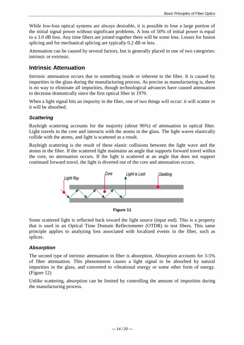
Basic Principles of Fiber Optics
mdash 16 20 mdash
Figure 14
Dispersion
Dispersion is the spreading of a light pulse as it travels down a fiber (See Figure 15) As
the pulses spread or broaden they tend to overlap and are no longer distinguishable by the
receiver as 0s and 1s Light pulses launched close together (high data rates) that spread too
much (high dispersion) result in errors and loss of information
Chromatic dispersion occurs as a result of the range of wavelengths in the light source Light
from lasers and LEDs consists of a range of wavelengths Each of these wavelengths travels at
a slightly different speed Over distance the varying wavelength speeds cause the light pulse
to spread in time This is of most importance in single-mode applications
Modal dispersion is significant in multimode applications where the various modes of light
traveling down the fiber arrive at the receiver at different times causing a spreading effect
Figure 15
Pulse width is measured at full width-half maximum in other words the full width of the
pulse at half the maximum pulse height Dispersion limits how fast or how much
information can be sent over an optical fiber
There are other effects of dispersion but further discussion is beyond the scope of this text
For more in-depth reading please consult the bibliography at the end of this publication
Bandwidth
In simplest terms bandwidth is the amount of information a fiber can carry so that every pulse
is distinguishable by the receiver at the end (Figure 16)
Basic Principles of Fiber Optics
mdash 17 20 mdash
Figure 16
As discussed in the previous section dispersion causes light pulses to spread The spreading
of these light pulses causes them to merge together At a certain distance and frequency the
pulses become unreadable by the receiver The multiple pathways of a multimode fiber cause
this overlap to be much greater than for single-mode fiber These different paths have
different lengths which cause each mode of light to arrive at a different time
System bandwidth is measured in megahertz (MHz) at one km In general when a systems
bandwidth is 200 MHzmiddotkm it means that 200 million pulses of light per second will travel
down 1 km (1000 meters) of fiber and each pulse will be distinguishable by the receiver
Check Your Understanding
Would you like to see how much youve learned
1 In optical fiber systems what are the typical wavelengths of operation
400 nm 455 nm 490 nm
620 nm 750 nm 800 nm
850 nm 1310 nm 1550 nm
2 What is an optical window
A glass object on the side of a building
A range of wavelengths at which fiber best operates
The moment in time when fiber became a commercially-viable enterprise
3 Which of the following is not true of attenuation
It is the loss of optical power as light travels down a fiber
It may be induced by scattering absorbing macrobending and microbending
It is measured in nanometers
4 What is bandwidth
A measure of the information-carrying capacity of an optical fiber
The side-to-side measurement of a wedding ring
A term used to express the total loss of an optical system
Fiber Manufacturing
There are several ways to manufacture optical fiber but this text will concentrate on the
method developed patented and used by the former Corning Glass Works now Corning
Incorporated
This method called Outside Vapor Deposition or OVD has three steps or phases laydown
consolidation and draw
Basic Principles of Fiber Optics
mdash 18 20 mdash
Laydown
In the laydown step a soot preform is made from ultrapure vapors of silicon tetrachloride and
germanium tetrachloride The vapors travel through a traversing burner and react in the flame
to form soot particles of silica and germania
Figure 17
The OVD process is distinguished by the method of depositing the soot These particles are
deposited on the surface of a rotating target rod The core material is deposited first followed
by the pure silica cladding Since both core and cladding raw materials are vapor-deposited
the entire preform is extremely pure
Consolidation
When deposition is complete the target rod is removed from the center of the porous preform
and the preform is placed into a consolidation furnace During the consolidation process the
water vapor is removed from the preform This high-temperature consolidation step sinters the
preform into a solid dense transparent glass blank The hole left by the target rod is fused
solid by the extremely high temperature of the draw furnace
Draw
The finished glass preform is placed in a draw tower and drawn into a continuous strand of
glass fiber First the blank is lowered into the top of the draw furnace
Basic Principles of Fiber Optics
mdash 19 20 mdash
Figure 18
The tip of the blank is heated until a piece of molten glass called a gob begins to fall from
the blank like hot taffy It pulls a thin strand of glass the beginning of an optical fiber
The fiber goes through a precise on-line diameter monitor to ensure specified outside
diameter Next coatings are applied and cured using ultraviolet lamps
At the bottom of the draw the fiber is wound on spools Each fiber is assigned a unique
identification number that encodes all relevant manufacturing data including raw materials
and manufacturing equipment
Note Extensive text and graphics in this Fiber Manufacturing section are used with
permission of Corning Communications
Check Your Understanding
Would you like to see how much youve learned
1 What are the three steps of fiber manufacture using the Outside Vapor Deposition (OVD)
method
Burner vapor fuel
Laydown consolidation draw
Gas glass spool
2 Which of the following is NOT true about the laydown stage of OVD fiber manufacture
A rotating target rod collects soot deposited from the burner
Basic Principles of Fiber Optics
mdash 20 20 mdash
The soot forms a preform
The preform is highly impure until it reaches the consolidation phase
3 Which of the following is NOT true about the consolidation stage of fiber manufacture
The removal of the target rod causes the core of the fiber to be hollow
Water vapor is removed from the preform
The white preform becomes a solid dense transparent glass blank
4 Which of the following is NOT true about the draw stage of fiber manufacture
The glass preform is drawn into a continuous piece of glass fiber
Fiber diameters are measured on-line
Coatings are applied and cured using infrared lamps
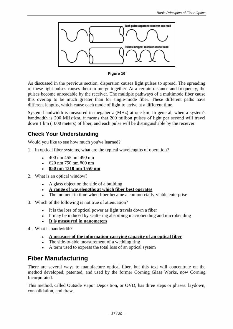
Basic Principles of Fiber Optics
mdash 17 20 mdash
Figure 16
As discussed in the previous section dispersion causes light pulses to spread The spreading
of these light pulses causes them to merge together At a certain distance and frequency the
pulses become unreadable by the receiver The multiple pathways of a multimode fiber cause
this overlap to be much greater than for single-mode fiber These different paths have
different lengths which cause each mode of light to arrive at a different time
System bandwidth is measured in megahertz (MHz) at one km In general when a systems
bandwidth is 200 MHzmiddotkm it means that 200 million pulses of light per second will travel
down 1 km (1000 meters) of fiber and each pulse will be distinguishable by the receiver
Check Your Understanding
Would you like to see how much youve learned
1 In optical fiber systems what are the typical wavelengths of operation
400 nm 455 nm 490 nm
620 nm 750 nm 800 nm
850 nm 1310 nm 1550 nm
2 What is an optical window
A glass object on the side of a building
A range of wavelengths at which fiber best operates
The moment in time when fiber became a commercially-viable enterprise
3 Which of the following is not true of attenuation
It is the loss of optical power as light travels down a fiber
It may be induced by scattering absorbing macrobending and microbending
It is measured in nanometers
4 What is bandwidth
A measure of the information-carrying capacity of an optical fiber
The side-to-side measurement of a wedding ring
A term used to express the total loss of an optical system
Fiber Manufacturing
There are several ways to manufacture optical fiber but this text will concentrate on the
method developed patented and used by the former Corning Glass Works now Corning
Incorporated
This method called Outside Vapor Deposition or OVD has three steps or phases laydown
consolidation and draw
Basic Principles of Fiber Optics
mdash 18 20 mdash
Laydown
In the laydown step a soot preform is made from ultrapure vapors of silicon tetrachloride and
germanium tetrachloride The vapors travel through a traversing burner and react in the flame
to form soot particles of silica and germania
Figure 17
The OVD process is distinguished by the method of depositing the soot These particles are
deposited on the surface of a rotating target rod The core material is deposited first followed
by the pure silica cladding Since both core and cladding raw materials are vapor-deposited
the entire preform is extremely pure
Consolidation
When deposition is complete the target rod is removed from the center of the porous preform
and the preform is placed into a consolidation furnace During the consolidation process the
water vapor is removed from the preform This high-temperature consolidation step sinters the
preform into a solid dense transparent glass blank The hole left by the target rod is fused
solid by the extremely high temperature of the draw furnace
Draw
The finished glass preform is placed in a draw tower and drawn into a continuous strand of
glass fiber First the blank is lowered into the top of the draw furnace
Basic Principles of Fiber Optics
mdash 19 20 mdash
Figure 18
The tip of the blank is heated until a piece of molten glass called a gob begins to fall from
the blank like hot taffy It pulls a thin strand of glass the beginning of an optical fiber
The fiber goes through a precise on-line diameter monitor to ensure specified outside
diameter Next coatings are applied and cured using ultraviolet lamps
At the bottom of the draw the fiber is wound on spools Each fiber is assigned a unique
identification number that encodes all relevant manufacturing data including raw materials
and manufacturing equipment
Note Extensive text and graphics in this Fiber Manufacturing section are used with
permission of Corning Communications
Check Your Understanding
Would you like to see how much youve learned
1 What are the three steps of fiber manufacture using the Outside Vapor Deposition (OVD)
method
Burner vapor fuel
Laydown consolidation draw
Gas glass spool
2 Which of the following is NOT true about the laydown stage of OVD fiber manufacture
A rotating target rod collects soot deposited from the burner
Basic Principles of Fiber Optics
mdash 20 20 mdash
The soot forms a preform
The preform is highly impure until it reaches the consolidation phase
3 Which of the following is NOT true about the consolidation stage of fiber manufacture
The removal of the target rod causes the core of the fiber to be hollow
Water vapor is removed from the preform
The white preform becomes a solid dense transparent glass blank
4 Which of the following is NOT true about the draw stage of fiber manufacture
The glass preform is drawn into a continuous piece of glass fiber
Fiber diameters are measured on-line
Coatings are applied and cured using infrared lamps
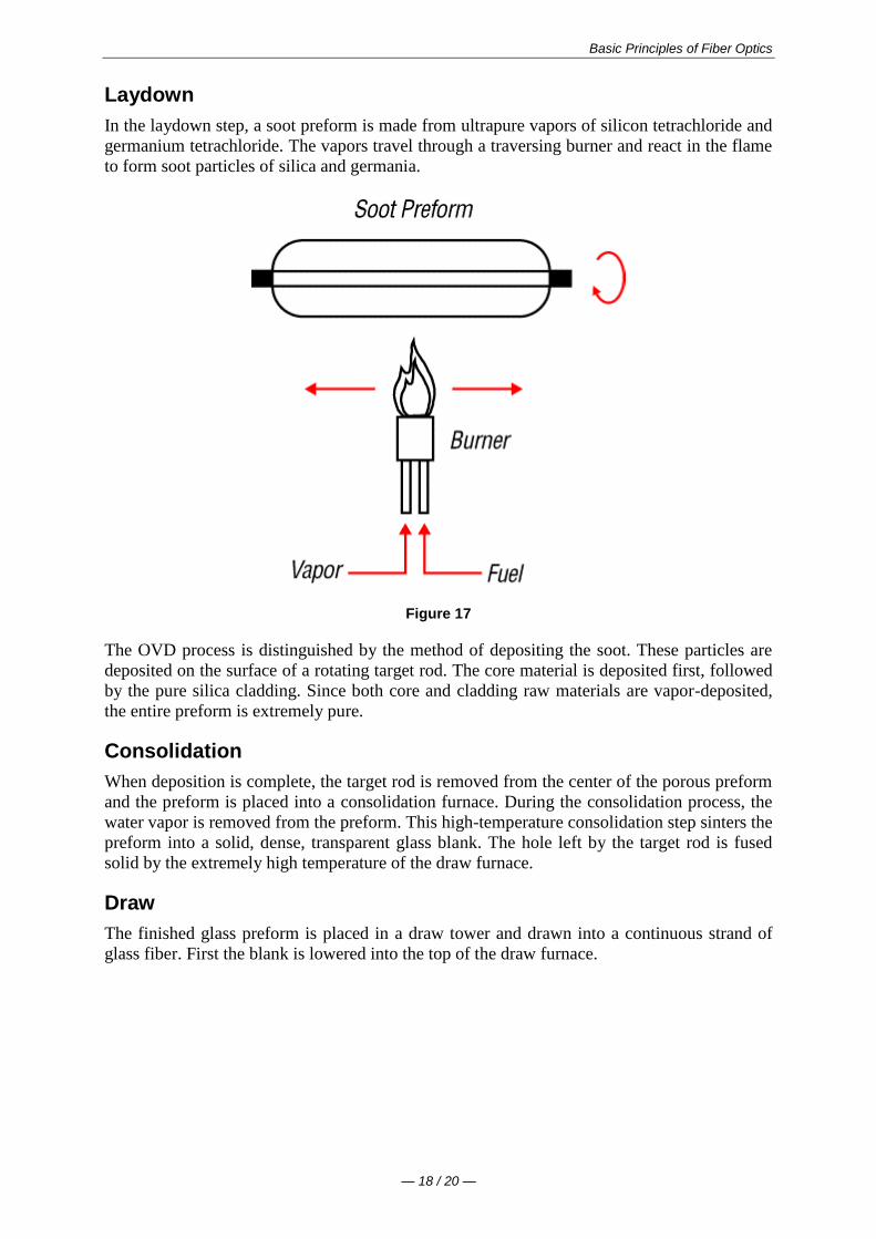
Basic Principles of Fiber Optics
mdash 18 20 mdash
Laydown
In the laydown step a soot preform is made from ultrapure vapors of silicon tetrachloride and
germanium tetrachloride The vapors travel through a traversing burner and react in the flame
to form soot particles of silica and germania
Figure 17
The OVD process is distinguished by the method of depositing the soot These particles are
deposited on the surface of a rotating target rod The core material is deposited first followed
by the pure silica cladding Since both core and cladding raw materials are vapor-deposited
the entire preform is extremely pure
Consolidation
When deposition is complete the target rod is removed from the center of the porous preform
and the preform is placed into a consolidation furnace During the consolidation process the
water vapor is removed from the preform This high-temperature consolidation step sinters the
preform into a solid dense transparent glass blank The hole left by the target rod is fused
solid by the extremely high temperature of the draw furnace
Draw
The finished glass preform is placed in a draw tower and drawn into a continuous strand of
glass fiber First the blank is lowered into the top of the draw furnace
Basic Principles of Fiber Optics
mdash 19 20 mdash
Figure 18
The tip of the blank is heated until a piece of molten glass called a gob begins to fall from
the blank like hot taffy It pulls a thin strand of glass the beginning of an optical fiber
The fiber goes through a precise on-line diameter monitor to ensure specified outside
diameter Next coatings are applied and cured using ultraviolet lamps
At the bottom of the draw the fiber is wound on spools Each fiber is assigned a unique
identification number that encodes all relevant manufacturing data including raw materials
and manufacturing equipment
Note Extensive text and graphics in this Fiber Manufacturing section are used with
permission of Corning Communications
Check Your Understanding
Would you like to see how much youve learned
1 What are the three steps of fiber manufacture using the Outside Vapor Deposition (OVD)
method
Burner vapor fuel
Laydown consolidation draw
Gas glass spool
2 Which of the following is NOT true about the laydown stage of OVD fiber manufacture
A rotating target rod collects soot deposited from the burner
Basic Principles of Fiber Optics
mdash 20 20 mdash
The soot forms a preform
The preform is highly impure until it reaches the consolidation phase
3 Which of the following is NOT true about the consolidation stage of fiber manufacture
The removal of the target rod causes the core of the fiber to be hollow
Water vapor is removed from the preform
The white preform becomes a solid dense transparent glass blank
4 Which of the following is NOT true about the draw stage of fiber manufacture
The glass preform is drawn into a continuous piece of glass fiber
Fiber diameters are measured on-line
Coatings are applied and cured using infrared lamps
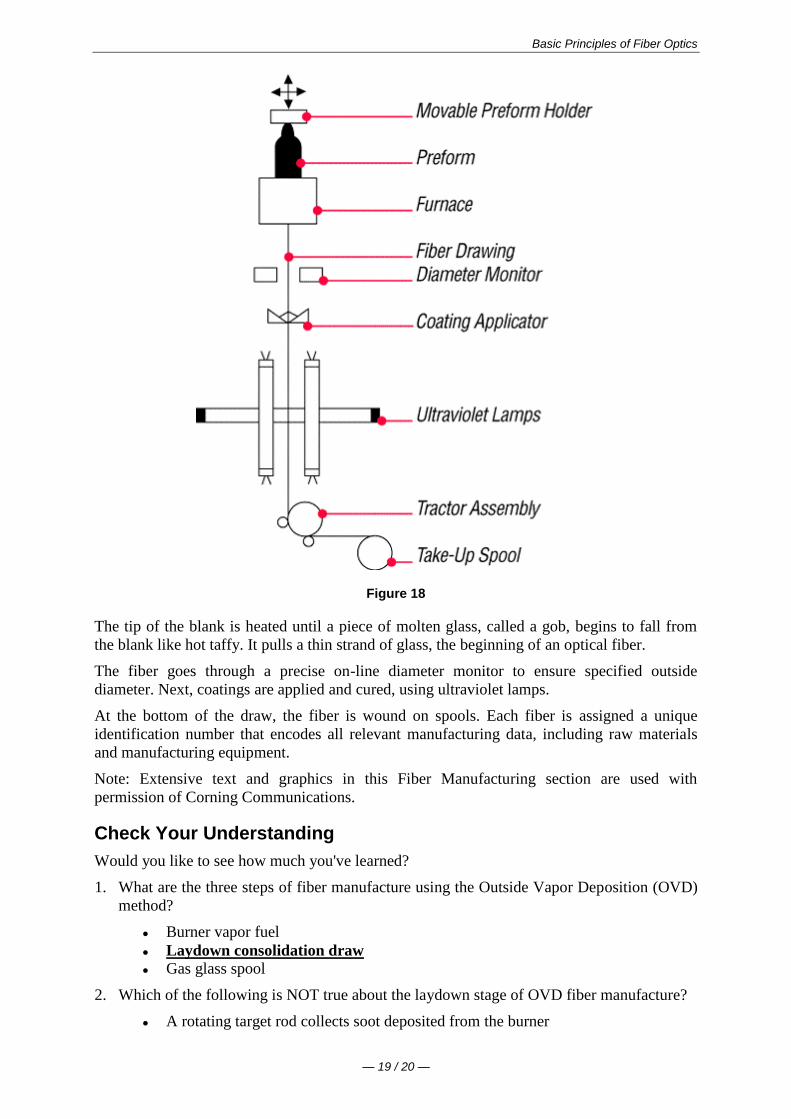
Basic Principles of Fiber Optics
mdash 20 20 mdash
The soot forms a preform
The preform is highly impure until it reaches the consolidation phase
3 Which of the following is NOT true about the consolidation stage of fiber manufacture
The removal of the target rod causes the core of the fiber to be hollow
Water vapor is removed from the preform
The white preform becomes a solid dense transparent glass blank
4 Which of the following is NOT true about the draw stage of fiber manufacture
The glass preform is drawn into a continuous piece of glass fiber
Fiber diameters are measured on-line
Coatings are applied and cured using infrared lamps