Embed Size (px)
Citation preview
SECTION 22 01} 0t
BASIC PLUMBING REQUIREMENTS
PART 1 GENERAL
1,01 SECTION INCLUDES
Basic Plumbing Requirements specifically applicable to Division 22 Sections, in additionto Division 1 - General Requirements.
"I .02 PLANS
These specifications are accompanied by plans indicating typical layouts, pipe andequipment location, etc. The plans and these specifications are complimentary each tothe other and what is called for by one shall be as binding as if called for by both. Shouldthere be a conflict between drawings and specifications regarding a material shown ofwork described or detailed then the material of work having the greater value shall be
provided.
The plans as prepared are in general diagrammatic. The contractor shall carefully lay outhis work at the site to conform to the architectural, mechanical, electrical and structural
conditions to provide grading of piping, to avoid all obstructions and to conform to detailsof installation as shown on the plans and supplied by the manufacturers of the equipmentto be installed, and thereby to provide an integrated satisfactorily operating installation.The General Contractor must coordinate the work of all trades. All necessary offsets
in piping, fittings, ductwork, etc, required to avoid interferences between piping,equipment, structural and architectural work are not shown but shall be furnished andinstalled by the contractor without additional expense to the Owner.
These specifications and plans accompanying same are intended to cover systems whichwill not interfere with the design of the building, which will fit into the available spaces, andwhich will insure complete and satisfactory systems. Each contractor shall, therefore,carefully examine the plans and the building and shall be responsible for the proper fittingof his material and apparatus into the building.
Contractor's attention is directed that all equipment he proposes to furnish shall fit into thespaces allocated for same on the plans. It shall be the Contractor's responsibility tofurnish data to evidence that sufficient space can be provided for the installation ofproposed equipment and that adequate access will exist for servicing and maintenance ofequipmant. Should changes become necessary during construction, the contractor shallmake such necessary changes at his (the Contractor's) own expense.
Exceptions and inconsistencies in plans and specifications shall be brought to theArchitect's attention no later than five (5) days prior to the bid date. Otherwise, theContractor shall be responsible for any and all changes and additions that may benecessary to accommodate his particular apparatus or equipment.
.03 CHANGES
Any changes from the plans necessary to make this work conform to the building as it isconstructed, to make this work fit the work of other trades or to make this work conform tothe rules of city and municipal bodies having jurisdiction shall be made by this contractor
Section 22 00 01 - Basic Plumbing Requirements - Page 1
at no additional cost to the Owner. However, no changes shall be made from the work
described on the plans and these specifications except on written order from theArchitect.
If any changes are required other than those mentioned above and the changes involveextra work on the part of the contractor, no charges for this extra work shall be allowedunless authorized in advance of the work by a written order from the Owner and/orArchitect stating the charges to be made for the work.
Proposed use of item or equipment other than that specified or indicated may requireredesign of structure, partitions, foundations, piping, wiring, or other parts of mechanical,electrical, or architectural layout. Redesign, new drawinas, and detailing required shall be#re#ared and submitted to Architect/Engineer for approval
Where approved deviation requires different quantity, size and arrangement of wiring,conduit, equipment, etc. from that specified or indicated, provide such items and all otheradditional equipment required by system at not additional cost to the Owner.
"I .04 PRE4NSTALLATION MEETINGS
A. Section 01 30 00- Administration Requirements: Pre-lnstallation Meetings,
B. Convene minimum one week prior to commencing work, when required.
1.05 PROTECTION
All work, equipment and materials shall be protected at all time to prevent damage orbreakage either in transit, storage, installation or testing. All openings shall be closed withcaps or p•ugs during installation.
All material and equipment shall be covered and protected against dirt, water, chemicais,and mechanical injury. Failure on the part of the contractor to provide adequateprotection will be cause for rejection of the unprotected equipment and materials. Inparticular, duc•ork insulation which becomes saturated will be rejected and must beremoved from the job.
1.06 EXISTING FACtUTIES
All piping, valves, fittings, switches, starters, conduit boxes and/or any other items ofmechanical or electrical equipment which are not in service at the completion of thiscontract shall be removed.
Where an existing service to existing building requires disconnection to facilitateinstallation of thie work, this Contractor shall include in his bid the cost of suchdisconnecting, re-routing and re-connecting. Where any existing facilities which are toremain occupied are affected by disconnection, re-routing or re-connection, then suchdisconnecting, re-connecting and re-routing shal• be done in such a manner so as not tointerrupt any service to the building, including but not limited to, sanitary sewer, domesticwater, fire protection, alarm, communications, natural gas, refrigerant piping and electricalpower. Satisfactory arrangements shall be made with local authorities and/or the variousutility companies involved,
Section 22 00 01 - Basic Plumbing Requirements - Page 2
The method of disconnecting, re-routing and re-connecting shall be as shown onthe Drawings, or if not shown on the drawings, subject to the approval of theArchitect and Owner.
Unless noted otherwise, all equipment and material indicated or specified to be removedshall become the property of the Owner and shall be removed from the site at thediscretion of the Owner.
This Contractor shall carefully coordinate work in and around existing services andequipment and adjoining rooms to remodel areas. Coordinate shut-down, removal,capping, and turn-on of existing services with the facilities' engineering department andgeneral contractor to provide continuous (uninterrupted) service throughout theconstruction period. This Contractor shall refer to the architectural plans andspecifications and thoroughly familiarize himself with the construction phasing in remodelareas before beginning work.
1.07 ACCESS PANELS
All valves, traps, drains, cleanouts, etc., must be accessible. The Contractor shall,wherever required to service his installation, coordinate size and location of accesspanels with General Contractor. Refer to Section 08 31 13 - Access Doors and Frames.
1.08 SUBSTITUTIONS
The materials, products and equipment described and specified establish a standard ofquality, function, dimension and appearance to be met by any proposed substitutions.
B. Reference Section 01 60 00 = Product Requirements.
1.09 SUBMITTALS
A. Submit under provisions of Section 01 33 00.
The Contractor shall furnish copies of the manufacturer's literature and drawingsdescribing all proposed equipment and materials indicated in the specifications. Theproposed use of the exact equipment and materials specified shall not change thisrequirement of including literature describing the proposed equipment. Manufactureditems proposed for use, whether specified or proposed for substitution, shall be thecurrent, catalogued product of the manufacturer, and replacement parts shall beavailable.
Manufacturer's regular catalog sheets will not be acceptable under this requirementunless they indicate completely all of the specification requirements and submittal pagelabeling criteria stated above. Where drawings cover several sizes or types ofconstruction they shall clearly indicate the size or type of construction to be used on theproject. In cases where several sizes of the same type of equipment are required to befurnished, the submittal shall include a schedule identifying each piece of equipment,
complete with all capacity information needed to compare every submitted item with itsrespective specified item.
Brochures shall contain a certification that the equipment or materials are suitable forconditions shown and specified; that the equipment or materials are believed to be inconformity with the plans and specifications, except as may be specifically described andthat approval is recommended. The certification shall be signed by the Contractor.
Section 22 00 0'1 - Basic Plumbing Requirements - Page 3
Brochures received not in conformity with these requirements will be returned for required
and marked for the Engineer's consideration.
Approval of the brochures, or any pert of the contents therein, shall not eliminateresponsibility for compliance with the plans and specifications, unless specific attentionhas been called in writing to proposed deviations at the time of transmittal of thebrochures and such deviations have been approved, nor shall it eliminate the
requirements or the responsibilities, if there are errors of any sort in the data submitted.
1.10 INTERFERENCES AND COOPERATION
The plans are generally diagrammatic and the Contractor shall coordinate the work of thedifferent trades so that interferences between piping, equipment, structural and
architectural work will be avoided, Not •!1 offsets in pi• duckerThe Contractor shall cooperate with the General Contractor and all other contractors tocoordinate their work to avoid interferences and delays and arrange all parts of the workto harmonize in service and appearance with all other parts.
The General Contractor shall coordinate the work of all trades. The various systems to
be installed shall follow the normal, common sense priority of systems installation with the
highest system to lowest system installation as follows:
HVAC Duct Work - shall be installed up and against building (fioedroof) structuralmembers.
Sanitary Waste and Storm Drainage Piping System shall begin horizontal routingas high as possible between structural members, offsetting vertically only to avoidconflict with structure or to drop below HVAC ductwork where offset isunavoidable.
Electrical Conduit shall be installed up, and against building structure, running
parallel with HVAC ductwork and offsetting up into structural bay (void) or belowHVAC ductwork to obtain a change in direction or branch take-off. Electricalconduit installation shall not control or dictate the routing or installation of theHVAC ductwork.
Domestic hot and cold water supply and hot water circulating return piping shallbe installed beside and below the HVAC ductwork and electrical conduit.
Preferred installation shall be on trapeze, wall brackets, or racked on verticalchannel on the wall above the ceiling line. The completed installation shall notconflict with the installation or removal of ceiling system components of tile. Allmain-run and branch take-off isolation valves shall be readily identifiable and
accessible from a standing position on a step ladder.
Fire sprinkler piping system shall be installed below all other systems andcomponents. The fire sprinkler piping shall not conflict with the installation orremoval of ceiling system components or tile. The fire sprinkler system pipinglayout and installation shall be coordinated by the fire sprinkler contractor and theGeneral Contractor with all other trades performing work in the affected area, toavoid conflict with the installation or removal of any ether systems components, or
to prevent ready access to valves, equipment of the other trades. Do not installsprinkler piping until ductwork mains are in place.
Section 22 00 01 - Basic Plumbing Requirements - Page 4
C. Refer to Section 01 30 00 for required overhead coerdinetion drawing submittals, ifrequired.
1,11 CUTTING AND PATCHING
1.I2
All cutting and patching of floors, walls and ceilings for installation of work covered inthese sections will be done by the General Contractor.
Where it becomes necessary to drill into or cut through any existing or completed floors,walls or ceilings to permit the installation of any work under this contract or to repair anydefects that may appear up to the expiration of the guarantee, such cutting and patchingshall be done by the General Contractor under the supervision of the Architect.
No joists, beams, girders or columns shall be cut without first obtaining written permissionfrom the Architect.
All drilling for expansion bolts, hangers and other supports shall be done subject to beapproval of the Architect. Labor and materials required to replace or rebuild parts orinjured portions shall be furnished at the Contractor's expense, subject to the satisfactionof the Architect.
PAINTING
A Surfaces to be painted and b•'pes of paint shall be as specified in the Architecturalspecifications.
A•I surfaces to be painted shall be thoroughly cleaned, all rust scraped off and all oil andgrease removed before any paint is applied.
C4 Finishing paint coats shall not be applied until all the plastering or other structural buildingwork is completed. Cloths shall be spread where necessary to prevent drops of paint, oil,etc. from defacing walls, floors, etc,, and the Contractor shall be held responsible for alldamage by neglect of such precautions. The finished conditions of the painting shall besubject to the approval of the Architect, who may require retouching or repainting ofsurfaces not properly finished,
1.13 MATERIALS AND WORKMANSHIP
1,14
All materials shall be new, of the quality specified and free of any defects. Manufacturer'snames are listed to establish a standard of quality and construction.
The Contractor will be responsible for transportation of his materials to the job and fortheir storage and protection until the final acceptance of the job,
Contractor shall furnish all necessary scaffolding, tackle, tools and appurtenances of allkinds and all labor required for the safe and expeditious execution of his contract.
UTILITIES
The Contractor shall arrange and pay for any necessary revisions to existing utilityservices, including meter deposits and connection fees to all serving utility companies andshall install utilities, where applicable.
Section 22 00 01 - Basic Plumbing Requirements - Page 5
"1.15 PERMITS AND INSPECTIONS
The Contractor shall be responsible for all permits and inspections required by law for thecompletion of his work. Cost of all permits and inspections shall be paid for by theContractor. The Contractor shall obtain and pay for all certificates of approval which mustbe delivered to the Architect before final acceptance of the job. All materials and labor
furnished by the Contractor shall be in strict accordance with the rules and requirementsof the National Board of Fire Underwriters, state and municipal regulations and other
authorities who may have lawful jurisdiction over the work being done. One (1) copy of allpermits obtained under this contract and all inspections performed and/or certificates ofacceptances, approval or beneficial occupancy received for this work, shall be forwardedto the Engineer.
Each contractor shall be responsible for coordinating their work with the GeneralContractor and scheduling progress inspections through the General Contractor to allowfor the following inspections to be performed without impeding the progress ofconstruction. Generally the Contractor shall plan for inspections to occur two (2) weeksprior to the scheduled concealment of work in the area of inspection.
C, The minimum inspections required for this project shall include but not be limited to:
Rough Wall: All utilities, services and systems in-place including wall studs,cross bracing, supports, etc. (No sheetrock or insulation).
Corrected Rou.qh Wail: (Before Sheetrock),
Above Ceiling: All utilities, services and systems in place, labeling on exposedpiping (No insulation on piping systems. Ceiling grid/channels may be installedbut no sheetrock or ceiling tile).
Above Ceiling Final: All utilities, services and systems complete includinghangers, insulation, and labeling (ceiling grid and/or channel may be in place butno sheetrock or ceiling tile shall be installed).
Substantial Completion: All surfaces complete, fixtures installed and trim-outcomplete.
7, Final: Cleaned and ready for occupancy
The Contractor shall be responsible for all costs associated with the extension of utilitiesto the Building, including but not limited to gas, water, sewage.
?1.'•6 EXAMINATION OF SITE
All Contractors submitting proposals for this work sha•l first examine the site and allconditions thereon and therein. All proposals shall take into consideration conditions asmay affect the work under this contract. They shall satisfy themselves as to existinggrades and the actual formation, and soil conditions.
They shall verify all service locations, depths, sizes, etc. No information given on theplans sha•l relieve the Contractor of this responsibility.
Section 22 00 01 - Basic Plumbing Requirements - Page 6
1.17 ESCUTCHEONS AND PLATES
Where pipes pass through ceilings or walls in finished spaces, install sectional plates orescutcheons to cover the annular opening between pipe and sleeve, Solid plates with setscrews shall be used where the sectional plates will not stay in place or are not availablein the required size, or where other individual specification section(s) require one piece orgreater quality escutcheons or plates.
Inside diameter of escutcheons shall fit around insulation and around pipe when not
insulated', outside diameter shall cover sleeve. Secure escutcheons or plates to pipe orsleeve but not to insulation. All escutcheons shall be triple nickel-chromium plated brass,
or type 316L stainless steel.
1.18 FIRESTOPPING
Firestopping: Unused slots, sleeves and other penetrations in floors, walls or othergeneral construction shall be closed and sealed with an approved firestopping material.
Reference Section 07 84 00 - Firestopping for appropriate firestoppin9 materialrequired for each wall rating and penetration size and type.
Floor slots and openings shall be closed with 16 gauge galvanized steel sheetsupported on 1-inch by 1-inch by 1/8-inch structural angle drilled or supportedwith powder-driven studs into the building structure. Firestop with a layer ofsilicone e•astomer not less than "]-inch thick which completely fills the opening.
The top surface of the silicone elastomer shall be approximately 1-inch below thefinished floor slab.
Openings in walls shall be closed with 16 gauge galvanized steel sheet securelyattached at the midpoint of the wall thickness and firestopped on both sides of thesteel sheet with not less than 1/8-inch thick layer of non-sagging silicone
elastomer to fully cover the opening.
Single or multiple pipes passing through wa•ls and floors shall have the annularspace between pipes or between pipes and structure filled with silicone elastomerto provide a 3-hour rated firestop for floors and walls.
Pipe and Ducts: The annulus between exposed pipe and ductwork and walls or floors. Infinished spaces shall be refilled, sealed and painted to match adjacent surfaces.
Future Slots: identify unused sleeves and slots for future use by permanently anchoredbrass nameplates identifying size and purpose of the covered slot.
1.20 QUALITY ASSURANCE
Perform Work in accordance with the International Building Code, 2009 edition,
International Mechanical 2009 Edition and international Plumbing Codea, 2009
edition, the local authority having jurisdiction, and the Architect/Engineer. As theminimum standard for the level of quality, in all cases the greater quantity or better qualityshall be the first consideration for the basis of an acceptable product or process. The
local authority having jurisdiction, the Architect and the Engineer shall have the finalauthority on the approval and/or use of any product or process specified or submitted forsubstitution. The greater quality and/or value specified herein for the system(s) andvarious components and installation procedures shall take precedence over the minimum
Section 22 00 01 - Basic Plumbing Requirements - Page 7
.21
requirements of the herein before mentioned codes or that of NFPA 13, NFPA 14, orNFPA 24 in all instances.
Equipment and Components: Bear UL and FM label or marking.
C. Welding Materials and Procedures: Perform to ASME Code.
Valves: 8ear UL/FM label or marking. Provide manufacturer's name and pressure ratingmarked on valve body.
Piping: AII piping installed on this project shall bear the complete ASTM andManufacturer's marking, labeling and identification requirements as required by ASTM.All installed piping 3'4" or greater in length shall be readily identifiable per ASTM labelingcriteria. Piping not bearing this identification upon installation shell be removed andreplaced by the correctly labeled piping. Piping shall not be re-stenciled after it isinstalled, to meet this requirement.
UNIONS
No unions are to be placed in any pipe in a location which will be concealed orinaccessible after completion of the building unless furnished with an access panel eitheras shown on the drawings or as specified herein. Unions must be installed on each sideof all pieces of equipment such as heating units, pumps, etc., so that such equipmentmay be readily disconnected.
1.22 iNSULATION
All insulation work, as specified hereinafter in the various sections, shall be performed bycontractors who principle form of endeavor is in the insulation application business= Theymust have been actively engaged in this line of work as a contractor for a period of notless than three years prior to the bid date of this project. All insulation materials used onthis project, including finishes and adhesives on the exterior surfaces of ducts, pipes andequipment shall have a flame spread rating of 25 or less and a smoke developed rating of50 or leas as determined by an independent testing laboratory in accordance with NFPA255q972 as required by #JFPA 90A.
PART 2 PRODUCTS
Not Used
PART 3 EXECUTION
Not Used
END OF SECTION
Section 22 00 01 - Basic Rumbing Requirements - Page 8
PART 1
1.0t
1.02
SECTION 22 05 29
HANGERS AND SUPPORTS FOR PLUMBING PiPiNG AND EQUIPMENT
GENERAL
SUMMARY
A. Section Includes:
1. Pipe hangers and supports.
2. Hanger rods,
3. •nserts.
4, Flashing.
5, Sleeves.
6, Mechanical sleeve seals.
7. Formed steel channel,
B. Related Sections:
1. Section 07 84 00 - Firestopping: Product requirements for firestopping forplacement by this section.
2. Section 07 g0 00 = Joint Protection: Product requirements for sea•ant materialsfor placement by this section,
3. Section 22 00 01 - General Plumbing Requirements.
4. Section 22 tl 00 = Facility Water Distribution: Execution requirements forplacement of hangers and supports specified by this section.
5. Section 22 t300 - Facility Sanitary Sewerage: Execution requirements forplacement of hangers and supports specified by this section.
REFERENCES
A. American Society of Mechanical Engineers:
1. ASME B31.1 - Power Piping,
2. ASME 831.5 - Refrigeration Piping.
3. ASME B31,9 - Building Services Piping.
B, ASTM International:
1. ASTM E84 - Test Method for Surface Burning Characteristics of BuildingMaterials.
Section 22 05 29 - Hangers and Supports for Plumbing Piping and Equipment = Page
t
1.04
2. ASTM E119 - Method for Fire Tests of Building Construction and Materials.
3. ASTM E814 - Test Method of Fire Tests of Through Penetration Firestops.
4. ASTM F708 - Standard Practice for Design and Installation of Rigid PipeHangers.
5. ASTM E1968 - Standard Test Method for Fire-Resistive Joint Systems.
C. American Welding Society:
1. AWS Dt .1 - Structural Welding Code - Steel.
D. FM Global:
1, FM - Approval Guide, A Guide to Equipment, Materials & Services Approved ByFactory Mutual Research For Property Conservation.
E. Manufacturers Standardization Society of the Valve and Fittings Industry:
1. MSS SP 58 - Pipe Hangers and Supports - Matarials, Design and Manufacturer.
2. MSS SP 69 - Pipe Hangers and Supports - Selection and Application.
3. MSS SP 89 - Pipe Hangers and Supports - Fabrication and Installation Practices.
F. Underwriters Laboratories Inc.:
1. UL 263 - Fire Tests of Building Construction and Materials.
2. UL 723 - Tests for Surface Burning Characteristics of Building Materials.
3. UL 1479 - Fire Tests of Through-Penetration Firestops.
4. UL 2079 - Tests for Fire Resistance of Building Joint Systems.
5, UL - Fire Resistance Directory.
G •ntertek Testing Services (Warnock Hersey Listed):
1. WH - Certification Listings.
DEFINITIONS
A, Firestopping (Through-Penetration Protection System): Sealing or stuffing material orassembly placed in spaces between and penetrations through building mataria[s to arrestmovement of fire, smoke, heat, and hot gases through fire rated construction,
SUBMITTALS
A. Section 01 33 00 - Submittal Procedures: Submittal procedures.
B, Shop Drawings: Indicate system layout with location including critical dimensions, sizes,and pipe hanger and support locations and detail of trapeze hangers.
Section 22 05 29 - Hangers and Supports for Plumbing Piping and Equipment- Page 2
t.05
1.06
1 •07
1.08
1.09
Product Data:
1, Hangers and Supports: Submit manufacturers catalog data including loadcapacity.
Design Data: Indicate load carrying capacity of trapeze, multiple pipe, end riser supporthangers. •ndicate calculations used to determine load carrying capacity of trapeze,multiple pipe, and riser support hangers.
E Manufacturer's Installation Instructions:
I. Hangers and Supports: Submit special procedures and assembly of components.
F. Manufacturer's Certificate: Certify products meet or exceed specified requirements.
QUALIFICATIONS
Manufacturer: Company specializing in manufacturing Products specified in this sectionwith minimum three (3) years documented experience.
Installer: Company specializing in performing Work of this section with minimum 3 yearsdocumented experience.
DELIVERY, STORAGE, AND HANDLING
A. Section 01 60 00 - Product Requirements: Requirements for transporting, handling,storing, and protecting products.
B. Accept materials on site in original factory packaging, labeled with manufacturer'sidentification.
C Protect from weather and construction traffic, dirt, water, chemical, and damage, bystoring in original packaging.
ENVIRONMENTAL REQUIREMENTS
A, Section 01 60 00 - Product Requirements: Environmental conditions affecting productson site.
FIELD MEASUREMENTS
A. Verify fie•d measurements prior to fabrication.
WARRANTY
A. Section 01 70 00 - Execution and Closeout Requirements: Product warranties and
product bonds.
PART 2 PRODUCTS
2.01 Acceptable Manufactures
1. B-Line
2, Grinnell
Section 22 05 29 - Hangers and Supports for Plumbing Piping and Equipment - Page 3
2.02 PIPE HANGERS AND SUPPORTS
A. Plumbing Piping - DW"V:
1. Conform to ASTM F708, MSS SP58, MSS SP69, MSS SP89,
2. Hangers for Pipe Sizes 1/2 to 1-1/2 inch: Malleable iron or Carbon stee•,adjustable swivel, split ring,
3, Hangers for Pipe Sizes 2 inches and Larger: Carbon steel, adjustable, clevis.
4, Multiple or Trapeze Hangers: Steel channels with welded spacers and hangerrods.
5. Wall Support for Pipe Sizes 3 inches and Smaller: Cast iron hook,
6. Wall Support for Pipe Sizes 4 inches and Larger: Welded steel bracket andwrought stee• clamp.
7. Vertical Support: Steel riser clamp.
8. Floor Support: Cast iron adjustable pipe saddle, lock nut, nipple, floor flange, andconcrete pier or steel support,
9. Copper Pipe Support: Copper-plated, carbon-steel adjustable, ring.
B• Plumbing Piping - Water:
'L Conform to ASTM F708, MSS SP58, MSS SP69, MSS SP89.
2. Hangers for Pipe Sizes 1/2 to '•-1/2 inch: Malleable iron or Carbon steel,adjustable swivel, split ring,
3. Hangers for Cold Pipe Sizes 2 inches and Larger: Carbon steel, adjustable,clevis.
4. Hangers for Hot Pipe Sizes 2 to 4 inches: Carbon steel, adjustable, c•evis.
5. Hangers for Hot Pipe Sizes 6 inches and Larger: Adjustable steel yoke, cast ironroll, double hanger.
6. Multiple or Trapeze Hangers: Steel channels with welded spacers and hangerrods,
7, Multiple or Trapeze Hangers for Hot Pipe Sizes 8 inches and Larger: Steelchannels with welded spacers and hanger rods, cast iron roll.
8. Wall Support for Pipe Sizes 3 inches and Smaller: Cast iron hook.
9. Wall Support for Pipe Sizes 4 inches and Larger: Welded steel bracket andwrought steel clamp.
10. Wall Support for Hot Pipe Sizes 6 inches and Larger: We•ded steel bracket andwrought steel clamp with adjustable steel yoke and cast iron roll.
11. Vertical Support: Steel riser c•amp at every floor.
Section 22 05 29 - Hangers and Supports for Plumbing Piping and Equipment- Page 4
12, Floor Support for Cold Pipe: Cast iron adjustable pipe saddle, lock nut, nipple,floor flange, and concrete pier or steel support.
13, Floor Support for Hot Pipe Sizes 4 inches and Smaller: Cast iron adjustable pipesaddle, lock nut, nipple, floor flange, and concrete pier or steel support,
14, Floor Support for Hot Pipe Sizes 6 inches and Larger: Adjustable east iron rolland stand, steel screws, and concrete pier or steel support.
t5. Copper Pipe Support: Copper-plated, Carbon-steal ring.
2.03 ACCESSORIES
A. Hanger Rods: Mild steel threaded both ends, threaded on one end, or continuousthreaded.
2.04 INSERTS
A, Inserts: Malleable iron case of [galvanized] steel shell and expander plug for threadedconnection with lateral adjustment, top slot for reinforcing rods, lugs for attaching toforms; size inserts to suit threaded hanger rods,
2.05 FLASHING
A. Metal Flashing: 20 gage thick galvanized steel.
B. Metal Counterflashing: 20 gage thick galvanized steel.
C Lead Flashing:
1. Waterproofing: 5 •bJeq. ff sheet lead.
2. Soundproofing: "] Ib./sq. ft sheet ]end,
D. Flexible Flashing: Compatible with roofing,
E, Caps: Steel, 22 gage minimum; ']6 gage at fire resistant elements.
2.06 SLEEVES
A Sleeves for Pipes Through Non-fire Rated F•oors: '•8 gage thick galvanized steel.
B, Sleeves for Pipes Through Non#ire Rated Beams, Walls, Footings, and Potentially WetFloors: Steel pipe or 18 gage thick galvanized steel,
C. Sealant: Refer to Section 07 90 00,
2.07 MECHANICAL SLEEVE SEALS
A. Product Description: Modular mechanical type, consisting of intedockin9 synthetic rubberlinks shaped to continuously fill annular space between object and sleeve, connectedwith bolts and pressure plates causing rubber sealing elements to expand whentightened, providing watertight eea• and electrical insulation.
Section 22 05 29 - Hangers and Supports for Plumbing Piping and Equipment - Page 5
2,08 FORMED STEEL CHANNEL
A. Product Description: Galvanized 12 gage thick steel. With holes 1-'h'2 inches on center
PART 3 EXECUTION
&01 EXAMiNATiON
A. Section 01 30 00 - Administrative Requirements:
before starting work.
Verification of existing conditions
B. Verify openings are ready to receive sleeves=
3.02 PREPARATION
A, Do not drill or cut sttuctural members.
& Obtain permission from Architec'dEngineer before drilling or catting structural members.
3.03 INSTALLATION = INSERTS
A. install inserts for placement in concrete forms.
B. Install inserts for suspending hangers from reinforced concrete slabs and sides ofreinforced concrete beams.
C. Provide hooked rod to concrete reinforcement section for inserts carrying pipe 4 inches
and larger,
D. Where concrete slabs form finished ceiling, locate inserts flush with slab surface.
E. Where inserts are omitted, drill through concrete slab from below and provide through-bolt with recessed square steel plate and nut recessed into and grouted flush with slab.
3.04 INSTALLATION - PIPE HANGERS AND SUPPORTS
A. Install in accordance with ASME 31.9, ASTM F708, MSS SP 69 and MSS SP 89.
8. Support horizontal piping as scheduled.
C. Install hangers with minimum lf2 inch space between finished covering and adjacentwork•
D. Place hangers within 12 inches of each horizontal elbow,
E, Use hangers with 1-112 inch minimum vertical adjustment,
F. Support horizontal cast iron pipe adjacent to each hub, with 5 feet maximum spacingbetween hangers,
G. Support vertical piping at every floor. Support vertical cast iron pipe at each floor at hub.
H. Where piping is installed in parallel and at same elevation, provide multiple pipe ortrapeze hangers.
Section 22 05 29 - Hangers and Supports for Plumbing Piping and Equipment - Page
&05
3.06
3.07
L Support riser piping independently of connected horizontal piping.
J. Provide copper plated hangers and supports for copper piping.
K Design hangers for pipe movement without disengagement of supported pipe,
L. Prime coat exposed steel hangers and supports. Refer to Section 09 90 00. Hangers andsupports located in crawl spaces, pipe shafts, and suspended ceiling spaces are notconsidered exposed.
M Provide clearance in hangers and from structure and other equipment for installation ofinsulation. Refer to Section 22 07 00.
INSTALLATION - FLASHING
A Provide flexible flashing and metal counterfleshing where piping penetrates weather orwaterproofed wails, floors, and roofs.
B F•ash vent and soi• pipes projecting 3 inches minimum above finished roof surface withlead worked I inch minimum into hub, 8 inches minimum clear on sides with 24 x 24
inches sheet size. For pipes through outside walls, turn flanges back into wall and caulk,metal counter-flash, and seal.
C. Flash floor drains in floors with topping over finished areas with lead, 10 inches clear onsides with minimum 36 x 36 inch sheet size. Fasten flashing to drain clamp device.
D. Seal floor, shower, mop, sink, root drains and floor drains watertight to adjacentmaterials.
E. Adjust storm collars tight to pipe with bolts; caulk around top edge. Use storm collarsabove roof jacks. Screw vertical flange section to face of curb.
INSTALLATION - SLEEVES
A. Exterior watertight entries: Seal with mechanical sleeve seals.
8. Set sleeves in position in forms. Provide reinforcing around sleeves.
C. Size sleeves large enough to allow for movement due to expansion and contraction.Provide for continuous insulation wrapping.
D Extend sleeves through floors 1 inch above finished floor •evel. Caulk sleeves.
E. Where piping penetrates floor, ceiling, or wall, close off space between pipe and adjacentwork with stuffing insulation and caulk [airtight]. Provide close fitting metal collar orescutcheon covers at both sides of penetration•
Install stainless steel escutcheons at finished surfaces.
FIELD QUAUTY CONTROL
A. Section 01 4000 - Quality Requirements, 01 7000 - Execution and Closeout
Requirements: Field inspecting, testing, adjusting, and balancing.
Section 22 05 29 - Hangers and Supports for Plumbing Piping and Equipment - Page 7
3,08 CLEANING
A. Section 01 70 00 - Execution and Closeout Requirements: Requirements for cleaning,
B. Clean adjacent surfaces of firestopping materials.
3.09 PROTECTION OF FINISHED WORK
A. Section 01 70 00 - Execution and Ctoseout Requirements: Requirements for protectingfinished Work.
Protect adjacent surfaces from damage by materia• installation.
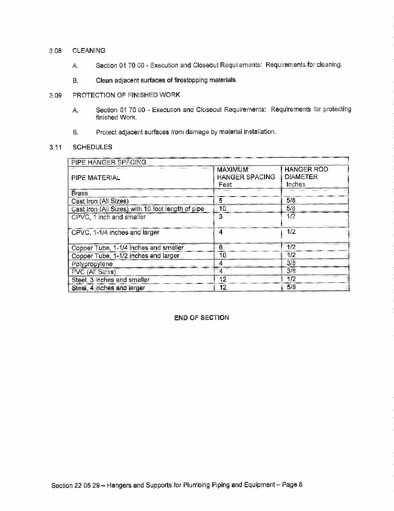
SCHEDULES3,11
MAXIMUM HANGER ROD
PIPE MATERIAL HANGER SPACING DIAMETERFeet Inches
Brass
CPVC, 1 inch and smaller 3
CPVCi %i/4 inches and larger 4
copper Tube, '1-1/4 inches and smaller 8
e, 1•!/2 inches and lar•er
Steel, 3 inches andsm•ller .......................... 12s•ee!, 4 inches and •ar 12
5/8
I/2
t/2
1/2
1/2
3/8
3/8
END OFSECTION
Section 22 05 29 - Hangers and Supports for Plumbing Piping and Equipment - Page 8
PART
1.02
1,03
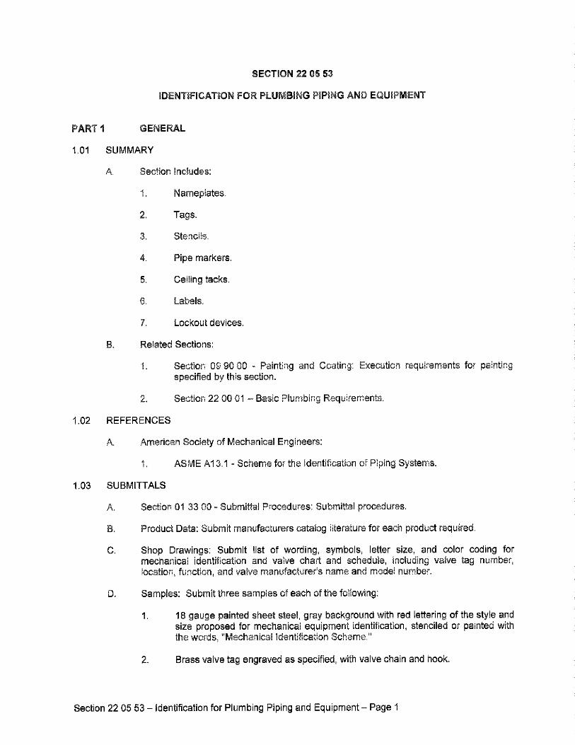
SECTION 22 05 53
IDENTIFICATION FOR PLUMBING PIPING AND EGUIPMENT
GENERAL
SUMMARY
A. Section
I.
2,
3,
4,
REFERENCES
Includes:
Nameplates.
Tags.
Stencils.
Pipe markers.
5. Ceiling tacks.
6. Labels.
7. Lockout devices,
Related Sections:
1= Section 09 90 00 = Painting and Coating: E?cution requirements for paintingspecified by this section
Section 22 O0 01 - Basic Plumbing Requirements.
A. American Society of Mechanical Engineers:
1. ASME A13,1 = Scheme for the identification of Piping Systems.
SUBMITTALS
A. Section 01 33 00 = Submittal Procedures: Submittal procedures,
B. Product Data: Submit manufacturers catalog literature for each product required.
C. Shop Drawings: Submit list of wording, symbols, letter size, and color coding formechanical identification and valve chart and schedule, including valve tag number,
location, function, and valve manufacturer's name and model number.
D. Samples: Submit three samples of each of the following:
1. 18 gauge painted sheet steel, gray background with red lettering of the style andsize proposed for mechanical equipment identification, stenciled or painted withthe words, "Mechanical •dentification Scheme."
2. Brass valve tag engraved as specified, with valve chain and hook.
Section 22 05 53 - identification for Plumbing Piping and Equipment - Page
1.04
F. Manufacturer's Installation
procedures, and installation.
CLOSEOUT SUBMITTALS
A.
B.
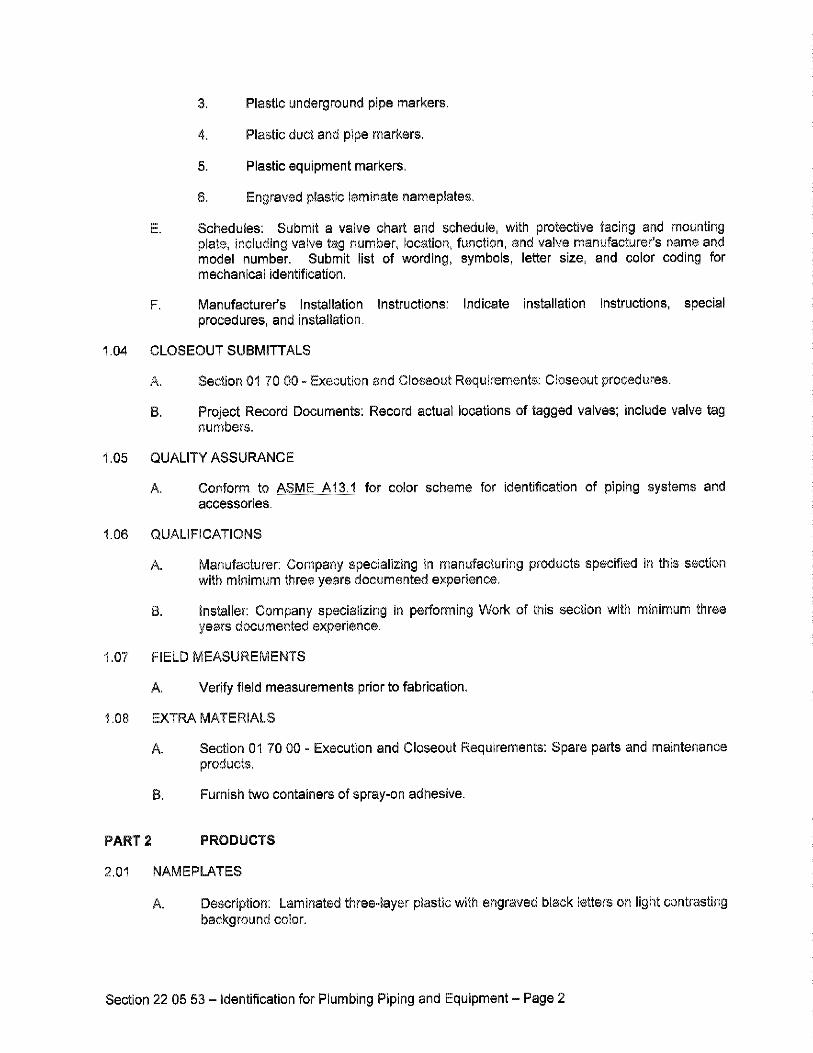
3. Plastic underground pipe markers.
4, Plastic duct and pipe markers.
5, Plastic equipment markers,
6, Engraved plastic laminate nameplates,
Schedules: Submit a valve chart and schedule, with protective facing and mountingplate, including valve tag number, location, function, and valve manufacturer's name andmodel number. Submit list of wording, symbols, letter size, and color coding formechanical identification,
Instructions: Indicate installation instructions, special
Section 01 70 00 - Execution end Closeout Requirements: Closeout procedures.
Project Record Documents: Record actual locations of tagged valves; include valve tagnumbers.
1.05 QUALITY ASSURANCE
A, Conform to ASME A13.t for color scheme for identification of piping systems andaccessories.
1.08 QUALIFICATIONS
A. Manufacturer: Company specializing in manufacturing products specified in this sectionwith minimum three years documented experience.
B. installer: Company specializing in performing Work of this section with minimum threeyears documented experience.
t.07 FIELD MEASUREMENTS
A, Verify field measurements prior to fabrication.
1.08 EXTRA MATERIALS
A. Section 01 70 00 - Execution and CIoseout Requirements: Spare parts and maintenance
products,
B, Furnish two containers of spray-on adhesive.
PART 2 PRODUCTS
2.01 NAMEPLATES
A. Description: Laminated three-layer plastic with engraved black letters on light contrastingbackground color.
Section 22 05 53 - identification for Plumbing Piping and Equipment - Page 2
2.02 TAGS
A. Metal Tags: Brass with stamped letters; tag size minimum 1-1•'2 inch square with smoothedges.
Chart: Typewritten letter size list in anodized aluminum frame.
2.03 PIPE MARKERS
A. Color: Conform to ASME A13.1.
8. Plastic Tape Pipe Markers: Flexible, vinyl film tape with pressure sensitive adhesivebacking and printed markings.
2.04 STENCILS
A. Stencils: With clean cut symbols and letters of following size:
1. Up to 2 inch Outside Diameter of Insulation or Pipe: 1/2-inch high letters.
2. 2-1/2 to 6 inches Outside Diameter of Insulation or Pipe: 1 inch high letters.
3. Over 6 inches Outside Diameter of Insulation or Pipe: 1 •3/4 inches high letters.
4. Ductwork and Equipment: 1-314 inches high letter&
B. Stencil Paint: As specified in Section 09900, semi-gloss enamel, colors and lettering sizeconforming to ASME A'13.1.
2.05 CEILING TACKS
A. Description: Steel with 3/4 inch diameter color coded head.
B. Color code as follows:
1. Yellow - HVAC equipment
2. Red - Fire dampers/smoke dampers
3. Green - Plumbing valves
4. Blue - Heating/cooling valves
2.06 PLASTIC EQUIPMENT MARKERS
A. General: Provide laminated plastic equipment markers for all items of mechanicalequipment.
B. Size: Size laminated plastic markers net less than one inch in height and three inches inlength with engraved lettering white on black not less than 1/4-inch in height. For largerpieces of equipment, size markers 1-1/2-inch in height by 4-1/2-inches long, of 3/32laminated plastic melamine with white on black lettering engraved not less than 1/16-inchdeep and 1/2-inch high.
Section 22 05 53 - Identification for Plumbing Piping and Equipment - Page 3
Attachment: Attach nameplates with rivets, stainless steel screws or bolts. Onequipment such as tanks and pumps which cannot be drilled or pierced, attachnameplates with brass chains and "S" hooks.
2.07 VALVE TAGS
Materials: Provide valve tags of 18 gauge solid polished brass with engraved lettering ornumbers.
1. Fill lettering or numbers with black paint.
Lettering shall be not less than '1/4-inch in height.
Numbers shall be not less than 1/2-inch in height.
Provide 5/32-inch diameter hole, brass chain and "S" hook for attachment to thevalve stem.
2.08 ENGRAVED PLASTIC LAMINATE SIGNS
General: Where indicated in other sections of the specifications, provide engraved
instruction signs, warning signs, operational instructions or other signs designated.
Emergency Operating Signs: For emergency instructions on sprinkler protection, fireprotection, air handledfan start-stop, foam generation, emergency generator starting, orother emergency operating instructions, provide engraved, laminate, melamine plastic,white on red, not less than 1/8-inch thick.
t. Provide concise written instructions on the emergency operation of the device
Letters shall be not less than 5/18-inch in height, engraved 1/16-inch deep in
block capital letters.
Information and Warning Signs: Provide general information and warning signs oflaminated, melamine plastic, not less than 1/8-inch thick, with white engraved lettering onblack, with letters not less than 1/4-inch in height, block capitals.
Attachment: Attach signs directly to the equipment with rivets, bolts or screws, ifpossible. OthepNise, attach signs with angle brackets, U-bolts, or metal plates held inplace to piping with stainless steel draw-bands.
Attachment with adhesives will not be permitted
Locate signs not less than 5 feet nor more than 6 feet 8 inches above theoperating floor, directly visible from an operating aisle.
Locate signs to preclude damage during maintenance and repair or by operatingtraffic.
2.09 VALVE SCHEDULES AND FRAMES
A. General: Provide valve schedules for a•l valves except:
Section 22 05 53 - Identification for Plumbing Piping and Equipment - Page 4
2.10
2.11
PART3
3,01
3.02
Schedules:
spaced.
2,
Chrome plated valves exposed in kitchens,
a. Chrome plated valves exposed in toilet rooms.b. Exterior sill cooks.
Freeze-proof hydrants,
Provide typed or machine printed schedules, one item per line, double
Printing shall be black on white, water-resistant, fungus-resistant paper.
For each valve, list the valve number, location, size, and use or operatingfunction.
3. Support schedules in full metal backed painted steel or extruded aluminumframes with removable, non-yellowing, clear plastic faces.
4. Screw or bolt schedules to equipment room wails where directed.
5. Coordinate valve numbers with valve tags so that no two valves or scheduleddevices have the same number.
DIRECTIONAL ARROWS
A= Flow Direction: Provide flow directional arrows either as part of duet and pipe markers or
separately, attached to pipes and ducts
1. Conform to requirements for markers.
2, Size to conform to ANSI A13.1. (1" wide minimum).
LOCKOUT DEVICES
A, Lockout Hasps:
1, Anodized aluminum hasp with erasable label surface; size minimum7-1;4 x 3 inches.
B. Valve Lockout Devices:
2, Steel device preventing access to valve operator, accepting lock shackle.
EXECUTION
PREPARATION
A. Degrease and clean surfaces to receive adhesive for identification materials
B. Prepare surfaces in accordance with Section 09 90 00 for stencil painting.
iNSTALLATION
A. Apply stencil painting in accordance with Section 09 90 00.
Section 22 05 53 = Identification for Plumbing Piping and Equipment - Page 5
identifying devices after completion of coverings and painting.
C. install plastic nameplates with corrosive-resistant mechanical fasteners, or adhesive.
Install labels with sufficient adhesive for permanent adhesion and seal with clear lacquer.For unfinished canvas covering, apply paint primer before applying labels.
E. Install tags using corrosion resistant chain. Number tags consecutively by location.
Install underground plastic pipe markers 6 to 8 inches below finished grade, directlyabove buried pipe.
Identify pumps, equipment, tanks, and water treatment devices with plastic nameplatesIdentify in-line pumps and other small devices with tags.
Identify control panels and major control components outside panels with plasticnameplates.
Identify valves in main and branch piping with tags.
J. Tag automatic controls, instruments, and relays. Key to control schematic.
Identify piping, concealed or exposed, with plastic pipe markers, identify service, flowdirection, and pressure. Install in clear view and align with axis of piping. Locateidentification not to exceed 10 feet on straight runs including risers and drops, adjacent toeach valve and tee, at each side of penetration of structure or enclosure, and at eachobstruction.
Provide ceiling tacks to locate valves or dampers above T-bar type panel ceilings. Locatein corner of panel closest to equipment.
3.03 INSTALLATION - GENERAL
Provide ceiling tacks to locate valves above T-bar type panel ceilings. Locate in corner ofpanel closest to equipment.
3,04 CONCEALED VALVES AND EQUIPMENT
Equipment Above Ceilings: Provide valve tagging and identification to equipment locatedabove ceilings, such as variable air volume boxes, plumbing, medical gas, fire protectionor mechanical, valves, traps, and other items before the ceilings are installed.
Finished Surfaces: Where identification is to be provided on surfaces which require
insulation, painting and finishing, install identification after covering and painting iscomplete.
3.05 P•PING SYSTEM •DENTIFICATION
General: Install pipe markers of one of the following types on each system indicated toreceive identification, and include arrows to show normal direction of flow:
Plastic pipe markers, with application systems as indicated under "Materials"paragraph in this Section. Install on pipe insulation segment where required forhot non-insulated pipes.
Section 22 05 53 - Identification for Plumbing Piping and Equipment - Page 6
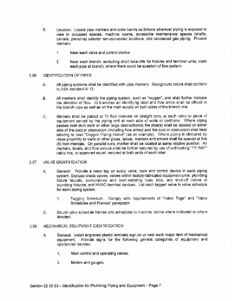
Location: Locate pipe markers and color bands as follows wherever piping is exposed toview in occupied spaces, machine rooms, accessible maintenance spaces (shafts,tunnels, plenums) exterior non-concealed locations, and concealed gas piping. Providemarkers:
Near each valve and control device.
Near each branch, excluding short rake-offs for fixtures and terminal units; markeach pipe at branch, where there could be question of flow pattern.
3.06 IDENTIFICATION OF PIPES
All piping systems shall be identified with pipe markers. Background colors shall conformto ASA standard A-13.
All markers shall identify the piping system, such as "oxygen", and shall further indicatethe direction of flow. At branches an identifying label and flow arrow shall be affixed to
the branch pipe as well as on the main supply on both sides of the branch line.
Markers shall be placed at 10 foot intervals on straight runs, at each valve or piece ofequipment served by the piping and at each side of walls or partitions. Where pipingpasses over duct work or other large obstruction(s) the pipe(s) shall be labeled on eitherside of the duct or obstruction (including flow arrow) and the duct or obstruction shall bear•abeling to read "Oxygen Piping Above" (as an example). Where piping is obscured byclose proximity to walls or other pipes, labels, markers and arrows shall be spaced at five(5) foot intervals. On parallel runs, marker shall be located at same relative position. Allmarkers, labels, and flow arrows shell be further secured by use of self-locking "TY-RAP"cable ties, or approved equal, secured at both ends of each label.
3.07 VALVE IDENTIFICATION
General: Provide e valve tag on every valve, cock and control device in each pipingsystem. Exclude check valves, valves within factory-fabricated equipment units, plumbingfixture faucets, convenience and lawn-watering hose bibs, and shut-off valves atplumbing fixtures, and HVAC terminal devices. List each tagged valve in valve schedulefor each piping system.
Tagging Schedule: Comply with requirements of "Valve Tags" and "ValveSchedules and Frames" paragraph.
Mount valve schedule frames and schedules in machine rooms where indicated or where
directed.
3.08 MECHANICAL EQUIPMENT •DENTIF•CAT•ON
General: Install engraved plastic laminate sign on or near each major item of mechanicalequipment. Provide signs for the following general categories of equipment andoperational devices:
1. Main control and operating valves.
Meters and gauges.
Section 22 05 53 - Identification for Plumbing Piping and Equipment - Page 7
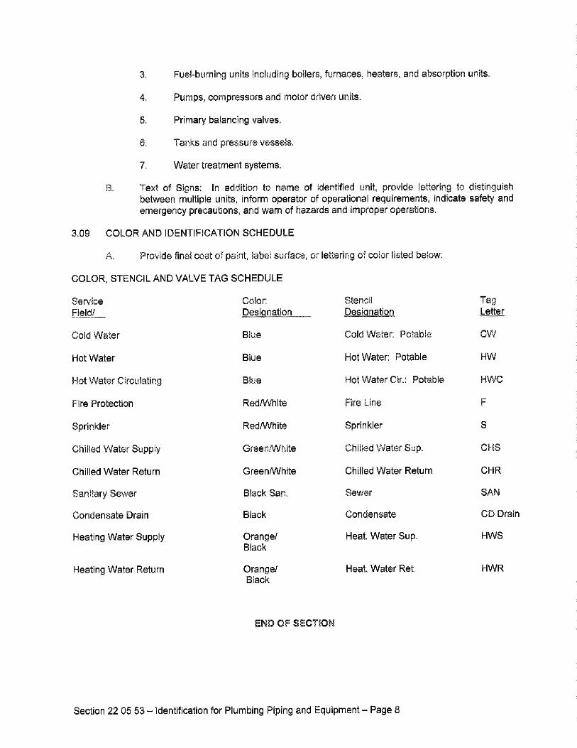
3. Fuel-burning units including boilers, furnaces, heaters, and absorption units.
4. Pumps, compressors and motor driven units.
5. Primary balancing valves•
6. Tanks and pressure vessels.
7. Water treatment systems.
Text of Signs: In addition to name of identified unit, provide lettering to distinguishbetween multiple units, inform operator of operational requirements, indicate safety andemergency precautions, and warn of hazards and improper operations.
3.09 COLOR AND IDENTIFiCATiON SCHEDULE
A. Provide final coat of paint, label surface
COLOR, STENCIL AND VALVE TAG SCHEDULE
Service Color:
Field/ DesiQnation.
Cold Water Blue
Hot Water Blue
Hot Water Circulating Blue
Fire Protection RedTWhite
Sprinkler RedNVhite
Chilled Water Supply Green/White
Chilled Water Return GreenANhite
Sanitary Sewer Black San.
Condensate Drain Black
Heating Water Supply Orange/Black
Heating Water Return Orange/Black
or lettering of color listed below:
Stencil Tag
Designation Letter
Cold Water: Potable CW
Hot Water: Potable HW
Hot Water Cir.: Potable HWC
Fire Line F
Sprinkler S
Chilted Water Sup, OIlS
Chilled Water Return CHR
Sewer SAN
Condensate CD Drain
Heat. Water Sup. HWS
Heat. Water Rot. HWR
END OF SECTION
Section 22 05 53 - Identification for Plumbing Piping and Equipment = Page 8
PART
1.02
SECTION 22 07 00
PLUMBING iNSULATiON
GENERAL
SUMMARY
A. Section includes:
1. Piping = Glass Fiber
2. Piping = Jackets
B. Related Sections:
1. Section 07 84 00 - Firestopping: Product requirements for firestopping forplacement by this section.
2. Section 09 90 00 - Painting and Coating: Execution requirements for paintinginsulation jackets and covering specified by this section.
3. Section 22 05 29 - Hangers and Supports for Plumbing Piping and Equipment:Product and Execution requirements for inserts at hanger locations.
4. Section 22 05 53 - Identification for Plumbing Piping and Equipment: Productrequirements for plumbing piping and equipment identification,
REFERENCES
A, ASTM international:
I. ASTM A167 - Standard Specification for Stainless and Heat=ResistingChromium-Nickel Steel Plate, Sheet, and Strip.
ASTM B209 - Standard Specification for Aluminum and Aluminum=Alloy Sheetand Plate,
ASTM C'177 - Standard Test Method for Steady-State Heat Flux Measurementsand Thermal Transmission Properties by Means of the Guarded=Hot=PlateApparatus.
ASTM C195 = Standard Specification for Mineral Fiber Thermal InsulatingCement.
ASTM C449;c44gM = Standard Specification for Mineral Fiber Hydraulic-SettingThermal Insulating and Finishing Cement.
ASTM C518 - Standard Test Method for Steady=State Heat Flux Measurementsand Thermal Transmission Properties by Means of the Heat Flow MeterApparatus.
ASTM C533 - Standard Specification for Calcium Silicate Block and PipeThermal Insulation.
Section 22 07 00 - Plumbing insulation - Page 1
.03
8. ASTM C534 - Standard Specification for Preformed Flexible Elastemeric CellularThermal insulation in Sheet and Tubular Form.
9. ASTM C547 - Standard Specification for Mineral Fiber Pipe Insulation.
t0. ASTM C552 - Standard Specification for Cellular Glass Thermal •nsulation,
t'1. ASTM C553 - Standard Specification for Mineral Fiber Blanket ThermalInsulation for Commercial and •ndustria• Applications.
12, ASTM C591 - Standard Specification for Unlaced Preformed Rigid CellularF•olyisocyanurate Thermal Insulation.
13. ASTM C592 - Standard Specification for Mineral Fiber Blanket Insulation andBlanket-Type Pipe Insulation (Metal-Mesh Covered) (Industrial Type).
14• ASTM C610 - Standard Specification for Molded Expanded Pedite Block andPipe Thermal Insulation.
'15. ASTM C6'12 - Standard Specification for Mineral Fiber Block and Board ThermalInsulation.
'18. ASTM C795 - Standard Specification for Thermal insulation for Use in Contactwith Auatenitic Stainless Steel.
'17. ASTM C921 - Standard Practice for Determining the Properties of JacketingMaterials for Thermal Insulation.
'18. ASTM C1126 - Standard Specification for Faced or Unfaced Rigid CellularPhenolic Thermal •nsulation.
19. ASTM C'1"•38 - Standard Specification for Flexible, Low Permeance VaporRetarders for Thermal Insulation.
20. ASTM D1784 - Standard Specification for Rigid Poly (Vinyl Chloride) (PVC)Compounds and Chlorinated Poly (Vinyl Chloride) (CPVC) Compounds.
2'1. ASTM E84 - Standard Test Method for Surface Burning Characteristics ofBuilding Materials,
22. ASTM E96 - Standard Test Methods for Water Vapor Transmission of Materials,
2& ASTM E162 - Standard Test Method for Surface F•ammability of Materials Usinga Radiant Heat Energy Source.
24. ASTM G21 - Standard Practice for Determining Resistance of Synthetic
Polymeric Materials to Fungi.
B. Sheet Metal and Air Conditioning Contractors':
1. SMACNA - HVAC Duct Construction Standard - Metal and Flexible.
SUBMITTALS
A. Section 0'• 33 00 - Submittal Procedures: Submittal procedures.
Section 22 07 00 - Plumbing Insulation - Page 2
1.04.
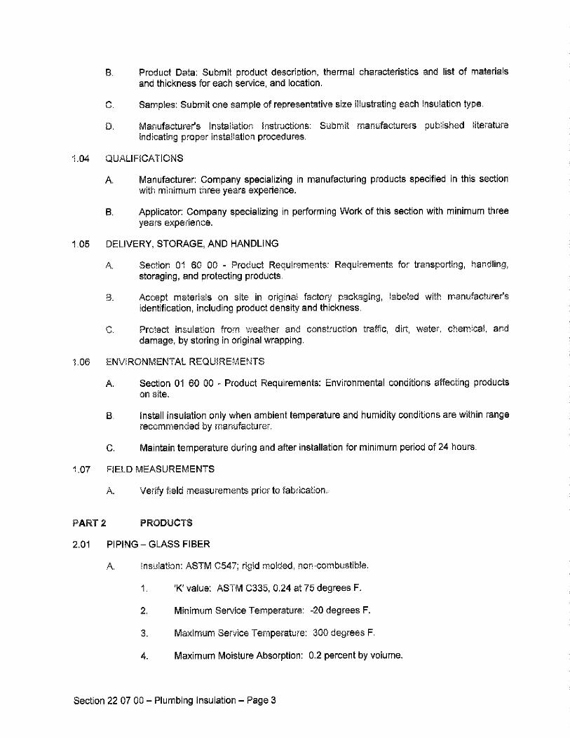
D. Manufacturer's Installation instructions:
indicating proper installation procedures.
QUAUFICATIONS
A,
Product Data: Submit product description, thermal characteristics and list of materialsand thickness for each service, and location,
Samples: Submit one sample of representative size illustrating each insulation type.
Submit manufacturers published literature
Manufacturer: Company specializing in manufacturing products specified in this sectionwith minimum three years experience.
Applicator: Company specializing in performing Work of this section with minimum threeyears experience.
1.05 DELIVERY, STORAGE, AND HANDLING
A Section 0I 80 00 - Product Requirements: Requirements for transporting, handling,atoraging, and protecting products.
B. Accept materials on site in original factory packaging, labeled with manufacturer'sidentification, including product density and thickness,
C• Protect insulation from weather and construction traffic, dirt, water, chemical, and
damage, by storing in original wrapping.
1,06 ENVIRONMENTAL REQUIREMENTS
A. Section 01 60 00 - Product Requirements: Environmental conditions affecting productson site,
B Install insulation only when ambient temperature and humidity conditions are within rangerecommended by manufacturer.
C, Maintain temperature during and after installation for minimum period of 24 hours.
1.07 FIELD MEASUREMENTS
A. Verify field measurements prior to fabrication•
PART 2
2.01
PRODUCTS
PIPING - GLASS FIBER
A Insulation: ASTM C547; rigid molded, non-combustible.
2.
3.
4=
'K' value: ASTM C335, &24 at 75 degrees F.
Minimum Service Temperature: -20 degrees F.
Maximum Service Temperature: 300 degrees F.
Maximum Moisture Absorption: 0.2 percent by volume.
Section 22 07 00 - Plumbing Insulation - Page 3
2.02
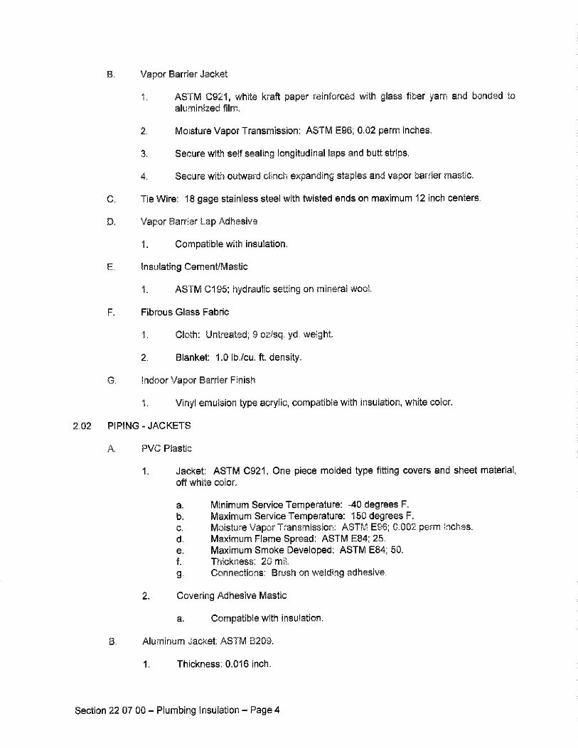
B. Vapor Barrier Jacket
1. ASTM C921, white kraft paper reinforced with glass fiber yarn and bonded toaluminized film.
2. Moisture Vapor Transmission: ASTM E96; &02 parm inches,
3, Secure with self sealing longitudinal laps and butt strips.
4. Secure with outward clinch expanding staples and vapor barrier mastic.
C. Tie Wire: 18 gage stainless steel with twisted ends on maximum 12 inch centers.
D. Vapor Barrier Lap Adhesive
1. Compatible with insu;ation,
E insulating Cement/Mastic
1. ASTM CI 95; hydraulic setting on mineral wool.
F, Fibrous Glass Fabric
1, C•oth: Untreated; 9 ozlsq, yd. weight.
2. Blanket: 1,0 Ib,;cu. ft, density,
G Indoor Vapor Barrier Finish
1, Vinyl emulsion type acrylic, compatible with insulation, white color.
PIPING - JACKETS
A, PVC Plastic
1. Jacket: ASTM C921, One piece molded type fitting covers and sheet material,off white color,
a. Minimum Service Temperature: -40 degrees F.b. Maximum Service Temperature: 150 degrees F.c. Moisture Vapor Transmission: ASTM E96; 0.002 perm inches.d. Maximum Flame Spread: ASTM E84; 25.
e. Maximum Smoke Developed: ASTM E84; 50.f. Thickness: 20 rail,
g Connections: Brush on welding adhesive.
2. Covering Adhesive Mastic
a. Compatible with insulation.
Aluminum Jacket: ASTM B209.
1. Thickness: 0.016 inch.
Section 22 07 00- Plumbing Insulation - Page 4
PART 3
3.0t
3.02
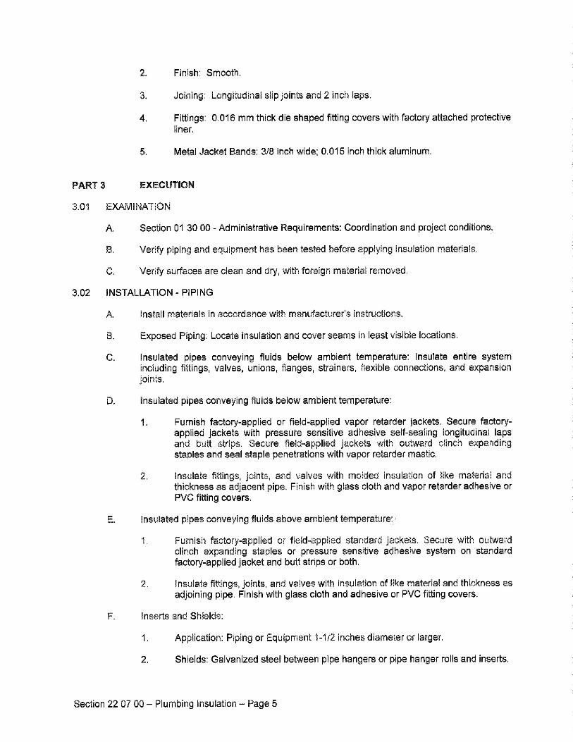
Finish: Smooth.
Joining: Longitudinal slip joints and 2 inch laps.
Fittings: 0.016 mm thick die shaped fitting covers with factory attached protectivetiner.
Metal Jacket Bands: 3/8 inch wide; 0.015 inch thick aluminum,
EXECUTION
EXAMINATION
A, Section 01 30 00 - Administrative Requirements: Coordination and project conditions
B, Verify piping and equipment has been tested before applying insulation materials,
C, Verify surfaces are clean and dry, with foreign material removed.
INSTALLATION = PiPiNG
A. Install materials in accordance with manufacturer's instructions.
El. Exposed Piping: Locate insulation and cover seams in least visible locations,
C, Insulated pipes conveying fluids below ambient temperature: Insulate entire systemincluding fittings, valves, unions, flanges, strainers, flexible connections, and expansionjoints.
D, insulated pipes conveying fluids below ambient temperature:
1 Furnish factory-applied or field-applied vapor retarder jackets. Secure factory-applied jackets with pressure sensitive adhesive self-sealing longitudinal •apsand butt strips. Secure field=applied jackets with outward clinch expandingstaples and seal staple penetrations with vapor retarder mastic.
2. Insulate fittings, joints, and valves with molded insulation of like material andthickness as adjacent pipe, Finish with glass cloth and vapor retarder adhesive orPVC fitting covers,
E. Insulated pipes conveying fluids above ambient temperature
1 Furnish factory-applied or field-applied standard jackets. Secure with outwardclinch expanding staples or pressure sensitive adhesive system on standardfactory-applied jacket and butt strips or both.
2• Insulate fittings, joints, and valves with insulation of like material and thickness asadjoining pipe. Finish with glass cloth and adhesive or PVC fitting covers,
F= Inserts and Shields:
t. Application: Piping or Equipment 1-1/2 inches diameter or larger.
2, Shields: Galvanized steel between pipe hangers or pipe hanger rolls and inserts,
Section 22 07 00 - Plumbing Insulation - Page 5
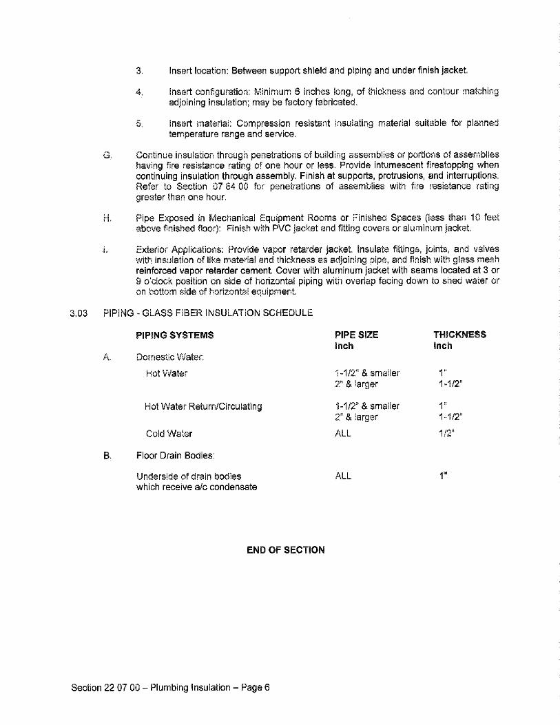
& Insert location: Bet,,veen support shield and piping and under finish jacket,
Insert configuration: Minimum 8 inches long, of thickness and contour matchingadjoining insulation; may be factory fabricated.
Insert material: Compression resistant insulating material suitable for plannedtemperature range and service,
Continue insulation through penetrations of building assemblies or portions of assemblieshaving fire resistance rating of one hour or less. Provide intumescent firestopping whencontinuing insulation through assembly. Finish at supports, protrusions, and interruptions,Refer to Section 07 84 00 for penetrations of assemblies with fire resistance ratinggreater than one hour.
Pipe Exposed in Mechanical Equipment Rooms or Finished Spaces (•ess than '10 feetabove finished floor): Finish with PVC jacket and fitting covers or aluminum jacket,
Exterior Applications: Provide vapor retarder jacket. Insulate fittings, joints, and valveswith insulation of like material and thickness as adjoining pipe, and finish with glass mashreinforced vapor retarder cement, Cover with aluminum jacket with seams located at 3 or9 o'clock position on side of horizontal piping with overlap facing down to shed water oron bottom side of horizontal equipment,
3.03 PIPING - GLASS FIBER INSULATION SCHEDULE
PiPiNG SYSTEMS PiPE SIZE THICKNESS
inch •nch
Domestic Water:
Hot Water 1-1/2"& smaller 1"
2" & larger 1=1t2"
Hot Water Return/Circulating
Cold Water
1-1/2" & smaller
2" & larger 1-1/2"
ALL 1/2"
B Floor Drain Bodies:
Underside of drain bodies
which receive a;c condensate
ALL 1"
END OF SECTION
Section 22 07 O0 - Plumbing •nsulation - Page
SECTION 22 tt 0g
FACiLiTY WATER DiSTRiBUTiON
PART
1,01
1.02
GENERAL
SUMMARY
A. Section Includes:
t= Domestic water piping, above grade=
2. Unions and flanges.
3. Valves.
4. Pipe hangers and supports.
5. Hose bibs.
& Hydrants.
7. Water hammer arrestors.
8. Recessed valve box=
9. Water Meter=
10. Backflow preventers.
B. Related Sections:
1.
REFERENCES
A.
Section 08 31 13 = Access Doors and Frames: Product requirements for accessdoors for placement by this section.
Section 09 g0 00 - Painting and Coating: Product and execution requirements forpainting specified by this section.
Section 22 00 0t = General Plumbing Requirements.
Section 22 05 29 = Hangers and Supports for Plumbing Piping and Equipment:Product requirements for pipe hangers and supports for placement by thissection=
Section 22 05 53 - •dentification for Plumbing Piping and Equipment: Productrequirements for pipe identification and valve tags for placement by this section.
Section 22 07 00 - Plumbing insulation: Product and execution requirements forpipe insulation.
American National Standards Institute:
1. ANSI Z21.22 - Relief Valves for Hot Water Supply Systems.
Section 22 11 00 - Facility Water Distribution - Page t
American Society of Mechanical Engineers:
1. ASME BI&I 8 - Cast Copper Alloy Solder Joint Pressure Fittings.
2. ASME B16.22 - Wrought Copper and Copper Alloy Solder Joint PressureFittings.
3. ASME B1&26 - Cast Copper Alloy Fittings for Flared Copper Tubes.
4 ASME B31.9 - Building Services Piping.
5. ASME 840.1 - Gauges - Pressure Indicating Dial Type - Elastic Element.
6. ASME Section VIII - Boiler and Pressure Vessel Code - Pressure Vessels.
7 ASME Section IX - Boiler and Pressure Vessel Code - Welding and BrazingQualifications.
American Society of Sanitary Engineering:
1,
2
ASTM
5.
B.
7.
8.
ASSE 1010 - Performance Requirements for Water Hammer Arresters.
ASSE 1011 - Performance Requirements for Hose Connection VacuumBreakers.
ASSE 1012 Performance Requirements for Backflow Preventer withIntermediate Atmospheric Vent.
ASSE t013 - Performance Requirements for Reduced Pressure PrincipleBackflow Preventers and Reduced Pressure Fire Protection Principle BackflowPreventers.
ASSE 1019 - Performance Requirements for Vacuum Breaker Wall Hydrants,Freeze Resistant, Automatic Draining Type.
international:
ASTM A53;A53M - Standard Specification for Pipe, Steel, Black and Hot-Dipped,Zinc-Coated, Welded and Seamless.
ASTM A2.34/A234M - Standard Specification for Piping Fittings of WroughtCarbon Steel end Alloy Steel for Moderate and High Temperature Service.
ASTM A395/A395M - Standard Specification for Ferritic Ductile Iron Pressure-Retaining Castings for Use at Elevated Temperatures.
ASTM A536 - Standard Specification for Ductile Iron Castings.
ASTM B32 - Standard Specification for Solder Metal.
ASTM B42 - Standard Specification for Seamless Copper Pipe, Standard Sizes.
ASTM B88 - Standard Specification for Seamless Copper Water Tube.
ASTM 8584 - Standard 8pecification for Copper Alloy Sand Castings for GeneralApplications.
Section 22 11 00 - Faci!!ty Water Distr!bution - Page 2
9. ASTM E1 - Standard Specification for ASTM Thermometers.
10. ASTM E77 Standard Test Method for Inspection and Verification ofThermometers.
11. ASTM F708 - Standard Practice for Design and Installation of Rigid PipeHangers.
12. ASTM F1476 - Standard Specification for Performance of Gasketed MechanicalCouplings for Use in Piping Applications.
American Welding Society:
1. AWS A&8 - Specification for Filler Metals for Brazing and Braze Welding.
American Water Works Association:
1. AVWVA C104 - American National Standard for Cement-Mortar Lining for Ductile-
•ron Pipe and Fittings for Water.
2. AVk,•IA C105 - American National Standard for Polyethylene Encasement forDuctile-Iron Pipe Systems.
3. AWWA Cl10 - American National Standard for Ductile-Iron and Grey-Iron
Fittings, 3 in. through 48 in. (75 mm through I200 mm), for Water and OtherLiquids.
4. AVWVA Cll 1 - American National Standard for Rubber-Gasket Joints for Ductile-
Iron Pressure Pipe and Fittings.
5. AWWA C151 - American National Standard for Ductile-Iron Pipe, CentrifugallyCast, for Water.
Manufacturers Standardization Society of the Valve and Fittings Industry:
2.
3.
5.
7.
8.
9.
10.
MSS SP 58 - F•ipe Hangers and Supports - Materials, Design and Manufacturer.
MSS SP 67 - Butterfly Valves.
MSS SP 69 - Pipe Hangers and Supports - Selection and Application.
MSS SP 70 - Cast Iron Gate Valves, F•anged and Threaded Ends.
MSS SP 7'1 - Cast Iron Swing Check Valves, Flanged and Threaded Ends.
MSS SP 78 - Cast Iron Plug Valves, Flanged and Threaded End&
MSS SP 80 - E•ronze Gate, Globe, Angle and Check Valves.
MSS SP 85 - Cast Iron Globe & Angle Valves, Flanged and Threaded.
MSS SP 89 - Pipe Hangers and Supports - Fabrication and Installation Practices.
MSS SP 110 - Ball Valves Threaded, Socket-Welding, Solder Joint, Grooved andFlared Ends.
Section 22 11 00 - Facility Water Distribution - Page 3
H. Plumbing and Drainage institute:
1. PDI WH201 - Water Hammer Arrester Standard.
1.03 SUBMITTALS
A, Section 01 33 00 - Submittal Procedures: Submittal procedures.
B, Product Data:
1, Piping: Submit data on pipe materials, fittings, and accessories. Submitmanufacturer's catalog information.
2, Valves: Submit manufacturers catalog information with valve data and ratings foreach service.
3. Hangers and Supports: Submit manufacturers catalog information including toadcapacity.
4. Domestic Water Specialties: Submit manufacturers catalog information,component sizes, roughqn requirements, service sizes, and finishe&
C. Manufacturer's Installation Instructions: Submit installation instructions for pumps, valvesand accessories.
D. Manufacturer's Certificate: Certify products meet or exceed specified requirements.
t .04 CLOSEOUT SUBMITTALS
A. Section 01 70 00 - Execution and Closeout Requirements: Closeout procedures.
B. Project Record Documents: Record actual locations of valves and equipment,
C, Operation and Maintenance Data: Submit spare parts list, exploded assembly views andrecommended maintenance intervals.
1.05 QUALIFiCATiONS
A. Manufacturer: Company specializing in manufacturing products specified in this sectionwith minimum three years documented experience.
8, Installer: Company specializing in performing Work of this section with minimum threeyears documented experience.
1.06 DELIVERY, STORAGE, AND HANDLING
A. Section 01 60 00 - Product Requirements: Product storage and handling requirements.
B. Accept valves and equipment on site in shipping containers with labeling in place. Inspectfor damage.
C. Provide temporary protective coating on cast iron and steel valves.
D. Provide temporary end caps and closures on piping and fittings, Maintain in place untilinstallation.
Section 22 11 00 - Facility Water Distribution - Page 4
E. Protect piping systems from entry of foreign materiels by temporary covers, completingsections of the Work, and isolating parts of completed system.
1.07 ENVIRONMENTAL REQUIREMENTS
A. Section 01 60 00 - Product Requirements.
B. Do not install underground piping when bedding is wet or frozen•
1.08 FIELD MEASUREMENTS
A. Verify field measurements prior to fabrication.
1.09 WARRANTY
A. Section 01 70 00 - Execution and CIoseout Requirements: Product warranties andproduct bonds.
B. Furnish 1 year manufacturer warranty for domestic water piping.
1.10 EXTRA MATERIALS
A. Section 01 70 00 - Execution and CIoseout Requirements: Spare parts and maintenanceproducts.
B. Furnish 1 packing kits for each size valve, 1 loose key for outside hose bibs, service kitsfor 1 pump seal for each pump model.
PART2
2.01
2.02
PRODUCTS
DOMESTIC WATER PIPING, ABOVE GRADE
A. Copper Tubing: ASTM B88, Type L, hard drawn.
t. Fittings: ASME B16.18, east copper alloy or ASME BI8.22, wrought copper andbronze.
2. Joints: Solder, lead free, [ASTM B32,] g5-5 tin-antimony, or tin and silver, withmelting range 430 to 535 degrees F. or Braze, AWS A58 8CuPsilvedphosphorus/copper alloy with melting range 1190 to 1480 degrees F.
UNIONS AND FLANGES
A. Unions for Pipe 2 inches and Smaller:
1. Ferrous Piping: Class 150, malleable iron, threaded.
2. Copper Piping: Class 150, bronze unions with [soldered] [brazed joints].
3. Dielectric Connections: Union with galvanized or plated steel threaded end,copper solder end, water impervious isolation barrier.
B. Flanges for Pipe 2-1/2 inches and Larger:
1. Ferrous Piping: Class 150, forged steel, slip-on flanges.
Section 22 11 00 - Facility Water Distribution - Page 5
Copper Piping: Class 150, slip-on bronze flange&
2.03 GATE VALVES
2 inches and Smaller: MSS SP 80, Class 125, bronze body, bronze trim, non*rising stem,hand-wheel, inside screw, solid wedge disc.
2-1/2 inches and Larger: MSS SP 70, Class 125, cast iron body, bronze trim, boltedbonnet, non-rising stem, hand-wheel, outside screw and yoke, solid wedge disc withbronze seat rings, flanged ends. Furnish chain-wheel operators for valves 6 inches andlarger mounted over 8 feet above floor.
2.04 BALL VALVES
2 inches and Smaller: MSS SP 110, 400 psi WOG two piece bronze body, chrome platedbrass ball, full port, teflon seats, blow-out proof stem, locking lever handle with balancingstops.
2 inches and Smaller: MSS SP 110, Class '150, bronze, two piece body, chrome plated
bronze ball, full por•, teflon seats, blow-out proof stem, locking lever handle withbalancing stops.
2 inches and Smaller: '150 psi at 73 degrees F water temperature, maximum servicetemperature: '•40 degrees F ASTM D'1784 F•VC body and ball, double lever handle,EPDM seals, teflon seats, full port.
2 inches and Smaller: 150 psi at 73 degrees F water temperature, maximum servicetemperature: 210 degrees F, ASTM D'•784 CPVC body and ball, double lever handle,EPDM seals, teflon seats, full port.
2.05 BUTTERFLY VALVES
A. 2-'1/2 inches and Larger: MSS SP 67, Class 150.
Body: Cast or ductile iron, [wafer] [lug] [or] [grooved] ends, stainless steal stem,extended neck.
2. Disc: stainless steel
3. Seat: Resilient replaceable Buna N.
4. Handte and Operator: 10 position lever handle.
2 inches through 10 inches: 150 psi at 73 degrees F water temperature, maximumservice temperature: 140 degrees F, two piece body, ASTM D1784 PVC, lug type flangefacing, disc encapsulated with EPDM, stainless steel shaft, locking lever handle.
2 inches through 10 inches: '150 psi at 73 degrees F water temperature, maximumservice temperature 210 degrees F, two piece body, ASTM D1784 CPVC, lug type flangefacing, disc encapsulated with EPDM, stainless steel shaft, locking lever handle.
PIPE HANGERS AND SUPPORTS: Refer to Section 22 05 29 Hangers and Supports for
Plumbing Piping and Equipment,
Section 22 11 00 - Facility Water Distribution - Page
2,07 HOSE BIBS
A, Acceptable Manufacturers:
1. Chicago.
2. T&S
3. MIFAB
4. Zum
5. Wade
6, Woodford
B. Refer to Plumbing Miscellaneous Schedule on project Drawings.
2.08 HYDRANTS
A. Acceptable Manufacturers:
1. Chicago
2. T&S
3. Zum
4. MIFAB
5. Wade
6. Woodford
B. Refer to Plumbing Miscellaneous Schedule on project Drawings.
2.09 RECESSED VALVE BOX
A. Refrigerator: Plastic preformed rough-in box with brass valves with wheel handle slip infinishing cover.
2.10 WATER HAMMER ARRESTORS
A. ASSE 1010: Copper construction, piston type sized in accordance with PDI WH-201.
B. Pre-charged suitable for operation in temperature range -100 to 300 degrees F andmaximum 150 psi working pressure.
2.11 DOMESTIC WATER METER
A. Water meter shall be of a nutating disc design made of cast bronze, with a low lead a•loydisc, chamber, housing and seals. The disc, which moves freely, nutates on its own bail,guided by a thrust roller. The meter shall have a direct magnetic drive. Meter shall becompliant with ANSI/AWWA standard C700. Provide with test plug.
B. Sensor: Nutating Disc, positive displacement
Section 22 t 1 00 - Facility Water Distribution - Page 7
2.12
C. Accuracy: According to AWWA Standard C700
D. Pulse transmitter: Provide for interfacing with the building automation system.
E. Manufacturers:
1, Badger Model 170 water meter with Model PFT=2 pulse transmitter,
BACKFLOW PREVENTERS
A. Reduced Pressure Backflow Preventers:
1. Comply with ASSE 1013,
2. Bronze body, with bronze internal parts and stainless steel springs.
3. Two independently operating, spring loaded check valves; diaphragm typedifferential pressure relief valve located between check valves; third check valveopening under back pressure in case of diaphragm failure; non-threaded ventoutlet; assembled with two gate valves, strainer, and four test cocks.
PART 3 EXECUTION
3.01 EXAMINATION
A. Section 01 30 00 - Administrative Requirements: Coordination and project conditions,
B. Verify excavations are to required grade, dry, and not over-excavatad,
3.02 PREPARATION
A, Ream pipe and tube ends. Remove burrs. [Bevel plain end ferrous pipe,]
B, Remove scale and dirt, on inside and outside, before assembly.
3,03 INSTALLATION - HANGERS AND SUPPORTS: Refer to Section 22 05 29
A. Install hangers and supports in accordance with Section 22 05 29.
3,04 INSTALLATION -ABOVE GROUND PIPING
A, Install non-conducting dielectric connections wherever jointing dissimilar metal&
B, Route piping in orderly manner and maintain gradient. Route parallel and perpendicularto walls.
C, install piping to maintain headroom without interfering with use of space or taking morespace than necessary.
D. Group piping whenever practical at common elevations,
E Slope piping and arrange systems to drain at low points.
F. Install piping to allow for expansion and contraction without stressing pipe, joints, orconnected equipment.
Section 22 11 00 - Facility Water Distribution - Page 8
J
K•
N
P•
R•
S•
Provide clearance in hangers and from structure and other equipment for installation ofinsulation and access to valves and fittings. Refer to Section 22 07 00.
Provide access where valves and fittings are not accessible. Coordinate size andlocation of access doors with Section 08 31 t3.
Where pipe support members are welded to structura• building framing, scrape, brushclean, and apply one coat of zinc rich primer to welding.
Prepare exposed, unfinished pipe, fittings, supports, and accessories ready for finishpainting. Refer to Section 09 90 00.
Install domestic water piping in accordance with ASME B31.9
Sleeve pipes passing through partitions, walls and floors. Refer to Section 22 05 29
Install unions downstream of valves and at equipment or apparatus connections.
Install valves with stems upright or horizontal, not inverted.
Install brass male adapters each side of valves in copper piped system. Solder adaptersto pipe.
Install gate, ball or butterfly valves for shut-off and to isolate equipment, part of systems,or vertical risers.
Install ball valves for throttling, bypass, or manual flow control services.
Provide lug end butterfly valves adjacent to equipment when functioning to isolateequipment.
Install potable water protection devices on plumbing lines where contamination ofdomestic water may occur; on boiler feed water lines, janitor rooms, fire sprinklersystems, premise isolation, irrigation systems, flush valves, interior and exterior hosebibs.
Install water hammer arrestors complete with accessible isolation valve on hot and coldwater supply piping to washing machine outlets and waterclosets.
3.05 FIELD QUALITY CONTROL
A. Section 01 4000 - Quality Requirements, 01 7000 - ExecutionRequirements: Field inspecting, testing, adjusting, and balancing.
B. Test domestic water piping system in accordance with applicable code.
3.06 CLEANING
A.
and Closeout
Prior to starting work, verify system is complete, flushed and clean.
Verify pH of water to be treated is between 7.4 and 7.6 by adding alkali (caustic soda orsoda ash) or acid (hydrochloric).
Inject disinfectant, free chlorine in liquid, powder and tablet or gas form, throughoutsystem to obtain residual from 50 to 80 mg/L.
Section 22 11 00 - Facility Water Distribution - Page 9
3.07
D. Bleed water from out•ats to obtain distribution and test for disinfectant residual at
minimum 15 percent of out•ets.
E. Maintain disinfectant in system for 24 hours.
F. When final disinfectant residual tests less than 25 rag/L, repeat treatment.
G. Flush disinfectant from system unti• residual concentration is equal to incoming water or1.0 mg/L.
H. Take samples no sooner than 24 hours after flushing, from [10] [5] [2] percent of outletsand from water entry, and analyze in accordance with AWWA C65'1.
SCHEDULES - See Drawings
END OF SECTION
Section 22 11 00 - Facility Water Distribution - Page 10
SECTION 22 t3 00
FACiLiTY SANITARY SEWE•,•GE
PART
1.01
,02
GENERAL
SUMMARY
A. Section Includes:
1, Sanitary sewer piping above grade.
2. Unions and flanges,
4. Pipe hangers and supports.
5. F•oer drains.
8. Floor sinks.
7. Cleanouts,
B, Re•ated Sections:
1, Section 08 32 13 - Access Doora and Frames: Product requirements for access
doors for placement by this section,
2. Section 09 90 00 - Painting and Coating: Product and execution requirements forpainting specified by this section.
3. Section 22 05 29 - Hangers and Supports for Plumbing Piping and Equipment:Product requirements for pipe hangers and supports [and firestopping] forplacement by this section.
4. Section 22 05 53 = identification for Plumbing Piping and Equipment: Product
requirements for pipe identification for placement by this sectien•
5, Section 22 07 00 - Plumbing Insulation: Product and execution requirements forpipe insulation.
REFERENCES
A American Society of Mechanicai Engineers:
2.
3.
4.
5.
6.
ASME A112.14.1 - Backwater Valves.
ASME Al12.21,1 - Floor Drains.
ASME B16,1 - Cast iron Pipe Flanges and Flanged Fittings,
ASME 816,3 - Malleable Iron Threaded Fittings,
ASME BI&4 - Gray iron Threaded Fittings,
ASME B18.23 - Cast Copper Alloy Solder Joint Drainage Fittings
Section 22 13 O0 - Facility Sanitary Sewerage - Page 1
7. ASME EH6.29 - Wrought Copper and Wrought Copper Alloy Solder JointDrainage Fittinge - DWV.
8. ASME B31.9 - Building Services Piping.
ASTM International:
1. ASTM A47/A47M - Standard Specification for Ferritic Malleable Iron Castings.
2. ASTM A53/A53M - Standard Specification for Pipe, Steel, Black and Hot-Dipped,Zinc-Coated, Welded and Seamless.
3. ASTM A74 - Standard Specification for Cast Iron Soil Pipe and Fittings,
4. ASTM A234/A2.34M - Standard Specification for Piping Fittings of WroughtCarbon Steel and Alloy Steel for Moderate and High Temperature Service.
5. ASTM A395/A395M - Standard Specification for Ferritic Ductile Iron Pressure-Retaining Castings for Use at Elevated Temperatures.
6. ASTM A536 - Standard Specification for Ductile •ron Castings,
7. ASTM A746 - Standard Specification for Ductile Iron Gravity Sewer Pipe.
8, B32 - Standard Specification for Solder Metal.
9. B42 - Standard Specification for Seamless Copper Pipe, Standard Sizee,
10. B43 - Standard Specification for Seamless Red Brass Pipe, Standard
11.
12.
13.
14,
15.
16.
17.
18,
20.
ASTM
ASTM
ASTM
Sizes.
ASTM
ASTM
ASTM
ASTM
B75 - Standard Specification for Seamless Copper Tube.
B75M - Standard Specification for Seamless Copper Tube (Metric).
B88 - Standard Specification for Seamless Copper Water Tube.
B88M - Standard Specification for Seamless Copper Water Tube (Metric).
ASTM B251 = Standard Specification for General Requirements for WroughtSeamless Copper and Copper-Alloy Tube.
ASTM B251M - Standard Specification for General Requirements for WroughtSeamless Copper and Copper-Alloy Tube (Metric),
ASTM 8302 - Standard Specification for Threadless Copper Pipe.
ASTM B306 - Standard Specification for Copper Drainage Tube
ASTM C478 - Standard Specification for Precast Reinforced Concrete ManholeSections.
ASTM 0478M - Standard Specification for Precast Reinforced Cor•crete ManholeSections (Metric),
Section 22 13 00 - Facility Sanitary Sewerage - Page 2
21.
22.
23.
ASTM C564 - Standard Specification for Rubber Gaskets for Cast Iron Soi• Pipeand Fittings.
ASTM C1053 - Standard Specification for Borosilicate Glass Pipe and Fittings forDrain, Waste, and Vent (DWV) Applications.
ASTM D1784 - Standard Specification for Rigid Poly (Vinyl Chloride) (PVC)Compounds and Chlorinated Poly (Vinyl Chloride) (CPVC) Compounds.
24.
25.
26.
27.
28.
29.
30.
31.
32.
33.
34.
35.
36.
37.
38.
ASTM D1785 - Standard Specification for Poly (Vinyl Chloride) (PVC) PlasticPipe, Schedules 40, 80, and 120.
ASTM D2235 - Standard Specification for Solvent Cement for Acrylonitrile-8utadiene-Styrene (ABS) Plastic Pipe and Fittings.
ASTM D2241 - Standard Specification for Poly (Vinyl Chloride) (PVC) Pressure-Rated Pipe (SDR Series).
ASTM D2464 - Standard Specification for Threaded Poly (Vinyl Chloride) (PVC)Plastic Pipe Fittings, Schedule 80.
ASTM D2466 - Standard Specification for Poly (Vinyl Chloride) (PVC) PlasticPipe Fittings, Schedule 40.
ASTM D2467 - Standard Specification for Po•y (Vinyl Chloride) (PVC) PlasticPipe Fittings, Schedule 80.
ASTM D2564 - Standard Specification for Solvent Cements for Poly (VinylChloride) (PVC) Plastic Piping Systems.
ASTM D2665 - Standard Specification for Poly (Vinyl Chloride) (PVC) PlasticDrain, Waste, and Vent Pipe and Fittings.
ASTM D2729 - Standard Specification for Poly (Vinyl Chloride) (PVC) SewerPipe and Fittings.
ASTM D2855 - Standard Practice for Making Solvent-Cemented Joints with Poly(Vinyl Chloride) (PVC) Pipe and Fittings.
ASTM D2996 - Standard Specification for Filament-Wound Fiberglass (Glass-Fiber-Reinforced Thermosetting Resin) Pipe.
ASTM D2997 - Standard Specification for Centrifugally Cast Fiberglass (Glass-Fiber-Reinforced Thermosetting-Resin) Pipe.
ASTM D3034 - Standard Specification for Type PSM Poly (Vinyl Chloride) (PVC)Sewer Pipe and Fittings.
ASTM 03262 - Standard Specification for Fiberglass (Glass-Fiber-ReinforcedThermosetting-Resin) Sewer F•ipe.
ASTM D3517 - Standard Specification for "Fiberglass" (Glass-Fiber"ReinforcedThermosetting-Resin) Pressure Pipe.
Section 22 13 00 - Facility Sanitary Sewerage - Page 3
1.03
39, ASTM D3754 - Standard Specification for "Fiberglass" (Glass-Fiber-ReinforcedThermosetting-Resin) Sewer and Industrial Pressure Pipe.
40, ASTM D3840 - Standard Specification for "Fiberglass" (Glass-Fiber-ReinforcedThermosetting-Resin) Pipe Fittings for Nonpressure Applications.
41 ASTM F477 - Standard Specification for Elastomeric Seals (Gaskets) for JoiningPlastic Pipe.
42 ASTM F708 - Standard Practice for Design and Installation of Rigid PipeHangers.
43 ASTM F1476 - Standard Specification for Performance of Gasketed MechanicalCouplings for Use in Piping Applications,
C. Cast Iron Soil Pipe institute
1. CISPI 301 - Standard Specification for Hub•ess Cast Iron Soil Pipe and Fittingsfor Sanitary and Storm Drain, Waste and Vent Piping Applications.
2 ClSPI 310 - Specification for Coupling for Use in Connection with Hubless CastIron Soil Pipe and Fittings for Sanitary and Storm Drain, Waste, and Vent PipingApplications.
D. Manufacturers Standardization Society of the Valve and Fittings Industry:
I. MSS SP 58 - Pipe Hangers and Supports - Materials, Design and Manufacturer.
2. MSS SP 69 - Pipe Hangers and Supports - Selection and Application.
3. MSS SP 70 - Cast Iron Gate Valves, Flanged and Threaded Ends.
4. MSS SP 71 - Cast •ron Swing Check Valves, Flanged and Threaded Ends.
5. MSS SP 80 - Bronze Gate, Globe, Angle and Check Valves.
6. MSS SP 89 - Pipe Hangers and Supports - Fabrication and •nstallation Practices.
7. MSS SP 110 - Ball Valves Threaded, Socket-Welding, Solder Joint, Grooved andFlared Ends.
E. Plumbing and Drainage •nstitute:
1. PDI G101 - Standard - Testing and Rating Procedure for Grease Interceptors.
SUBMITTALS
A. Section 01 33 00 - Submittal Procedures: Submittal procedures.
B. Shop Drawings: Indicate dimensions, weights, and placement of openings and holes forsewage-ejectors, and manholes.
C. Product Data:
1. Piping: Submit data on pipe materials, fittings, and accessories. Submitmanufacturers catalog information.
Section 22 13 O0 - Facility Sanitary Sewerage - Page 4
2. Hangers and Supports: Submit manufacturers catalog information including loadcapacity.
3. Sanitary Drainage Specialties: Submit manufacturers catalog information,component sizes, rough-in requirements, service sizes, and finishes.
D. Manufacturer's Installation Instructions: Submit installation instructions for material and
equipment,
E, Manufacturer's Certificate: Certify products meet or exceed specified requirements.
1,04 CLOSEOUT SU SM•TTALS
A. Section 01 70 00 - Execution and Closeout Requirements: Closeout procedures.
8. F•roject Record Documents: Record actual locations of equipment and clean-outs.
C. Operation and Maintenance Data: Submit frequency of treatment required forinterceptors. Include, spare parts lists, exploded assembly views for pumps andequipment.
1.05 QUALIFICATIONS
A, Manufacturer: Company specializing in manufacturing products specified in this sectionwith minimum three years documented experience,
B, Installer: Company specializing in performing Work of this section with minimum threeyears documented experience.
1•06 DELIVERY, STORAGE, AND HANDLING
A. Section 01 80 00 - Product Requirements: Product storage and handling requirements,
B. Protect piping systems from entry of foreign materials by temporary covers, completingsections of the Work, and isolating parts of completed system,
1.07 ENVIRONMENTAL REQUIREMENTS
A. Section 01 80 00 - Product Requirements.
B, Do not install underground piping when bedding is wet or frozen,
1,08 F•ELD MEASUREMENTS
A. Verify field measurements prior to fabrication.
1.09 WARRANTY
A. Section 0•1 70 00 - Execution and Closeout Requirements: Product warranties andproduct bonds.
B. Furnish 1 year manufacturer warranty for material
Section 22 13 00 - Facility Sanitary Sewerage - Page 5
PART2
2,01
2.02
2.03
PRODUCTS
SANITARY SEWER PIPING, ABOVE GRADE
All cast iron soil pipe and fittings sha•l be marked with the collective trademark of the Cast ironSoil Pipe Institute or receive prior approval of the Engineer. Manufacturers of cast iron soil pipeand fittings, AB&I, Charlotte Pipe or Tyler Pipe.
A. Cast iron Pipe: ASTM A74, service weight.
1. Fittings: Cast iron, ASTM A74.
2. Joints: ASTM C564, rubber gasket joint devices or lead and oakum,
8. Cast iron Pipe: ClSPI 301, hub=less, service weight.
1, Fittings: Cast iron, CISPI 301
2, Joints: CISP• 310, neoprene gaskets and stainless steel clamp=and-shieldassemblies.
FLOOR DRAINS: As Scheduled
CLEANOUTS: As Scheduled
A; interior Finished Floor Areas: Galvanized cast iron body with anchor flange, [reversibleclamping collar,] threaded top assembly, and round scored cover with gasket in serviceareas and [round] [square] depressed cover with gasket to accept floor finish in finishedfloor areas.
B interior Finished Wall Areas: Line type with lacquered cast iron body and round epoxycoated cover with gasket, and round stainless steel access cover secured with machinescrew.
C Interior Unfinished Accessible Areas: Calked or threaded type, Provide bolted stackcleanouts on vertical rainwater leaders.
PART3
3,01
3.02
EXECUTION
EXAMINATION
A, Section 01 30 00 - Administrative Requirements: Coordination and project conditions.
PREPARATION
A. Ream pipe and tube ends. Remove burrs. [Bevel plain end ferrous pipe.]
B. Remove scale and dirt, on inside and outside, before assembly.
C. Prepare piping connections to equipment with flanges or unions.
D. Keep open ends of pipe free from scale and dirt. Protect open ends with temporary plugsor caps.
Section 22 13 00 - Facility Sanitary Sewerage = Page 6
3,03 INSTALLATION - HANGERS AND SUPPORTS
A Insets:
1. Provide inserts for placement in concrete forms.
Provide inserts for suspending hangers from reinforced concrete slabs and sidesof reinforced concrete beams,
Provide hooked rod to concrete reinforcement section for inserts carrying pipe 4
inches and larger,
4 Where concrete slabs form finished ceiling, locate inserts flush with slab surface.
Where inserts are omitted, drill through concrete slab from below end provide
through-bolt with recessed square steel plate and nut [above] [flush with top of][recessed into and grouted flush with] slab,
B, Pipe Hangers and Supports:
1. Install in accordance with MSS SP 89.
2 Support horizontal piping as scheduled,
install hangers to provide minimum 1/2 inch space between finished coveringand adjacent work.
Place hangers within 12 inches of each horizontal elbow,
Use hangare with 1-I/2 inch minimum vertical adjustment, Design hangers forpipe movement without disengagement of supported pipe.
Support vertical piping at every [other] floor. Support riser piping independently ofconnected horizontal piping.
Where installing several pipes in parallel and at same elevation, provide multiplepipe hangers or trapeze hangers,
Provide copper plated hangers and supports for copper piping sheet leadpacking between hanger or support and piping,
Primo coat exposed steel hangers and supports. Refer to Section 09 90 00.Hangers and supports located in crawl spaces, pipe shafts, and suspendedceiling spaces are not considered exposed.
10. Install hangers adjacent to motor driven equipment with vibration isolation; referto Section 21 05 48,
3.04 INSTALLATION - ABOVE GROUND PIPING
Establish invert elevations, slopes for drainage to 1/8 inch per foot minimum. Maintaingradients,
Extend cleanouts to finished floor or wall surface. Lubricate threaded cleanout plugs with
mixture of graphite and linseed oil, Provide clearances at cleanout for snaking drainagesystem.
Section 22 13 00 - Facility Sanitary Sewerage - Page 7
3.06
D.
E.
F.
L.
M.
FIELD
A.
Encase exterior oleanouts in concrete flush with grade,
Install floor cleanouts at elevation to accommodate finished floor.
Provide non-conducting dielectric connections wherever jointing dissimilar metals.
Route piping in orderly manner and maintain gradient, Route parallel and perpendicularto walls.
Install piping to maintain headroom. Do not spread piping, conserve space.
Group piping whenever practical at common elevations.
Provide clearance in hangers and from structure and other equipment for installation ofinsulation, Refer to Section 22 07 00.
Provide access where valves and fittings are not accessible, Coordinate size andlocation of access doors with Section 08 3t 13.
install piping penetrating roofed areas to maintain integrity of roof assembly,
Where pipe support members are welded to structural building framing, scrape, brushclean, and apply one coat of zinc rich primer to welding,
Prepare exposed, unfinished pipe, fittings, supports, and accessories ready for finishpainting. Refer to Section 09 90
install bell and spigot pipe with belt end upstream.
Sleeve pipes passing through partitions, walls and floors,
Support cast iron drainage piping at every joint.
QUALITY CONTROL
Section 01 4000 - Quality Requirements 01 7000 Execution and CloseoutRequirements: Field inspecting, testing, adjusting, and balancing,
Test sanitary waste and vent piping system in acc,•rdance with UPC 2006 applicablecode or •ocal authority having jurisdiction.
END OF SECTION
Section 22 t3 00 - Facility Sanitary Sewerage - Page 8
SECTION 22 40 00
PLUMBING FIXTURES
GENERAL
SUMMARY
A, Section Includes:
1. Water closets.
2• Urinal&
3= Lavatories,
4, Sinks.
5, Service sinks.
8, Electric water coolers.
B, Related Sections:
1. Section 07 90 00 - Joint Protection: Product requirements for calking betweenfixtures and building components for placement by this section.
2, Section 22 00 01 - General Plumbing Requirements,
3, Section 22 1'1 00 - Facility Water Distribution: Supply connections to plumbingfixtures,
4. Section 22 13 00 - Facility Sanitary Sewerage: Waste connections to plumbingfixtures.
5. Section 26 05 03 - Equipment Wiring Connections: Execution requirements forelectric connections to sensor valves and faucets specified by this section.
REFERENCES
A. American National Standards •nstitute:
1. ANSI At "17/I = Accessible and Usable Buildings and Facilities.
2. ANSI Zt24.1 - Plastic Bathtub Units.
3. ANSI Z124.2 - Plastic Shower Units,
4. ANSi Z358.I - Emergency Eyewash and Shower Equipment.
B, Air-Conditioning and Refrigeration Institute:
'L AR11010 - Self-Contained, Mechanically Refrigerated Drinking-Water Coolers.
Section 22 40 00 - Plumbing Fixtures - Page 1
.03
1,04
American Society of Mechanical Engineers:
1. ASME Al12.6.1 - Floor-Affixed Supports for Off4he-FIoor Plumbing Fixtures forPublic Use.
2. ASME A112.18.1 - Plumbing Fixture Fittings.
3. ASME A112.19.1M - Enameled Cast Iron Plumbing Fixtures.
4. ASME A112.19,2M - Vitreous China Plumbing Fixtures.
5. ASME A112•19.3 - Stainless Steel Plumbing Fixtures (Designed for ResidentialUse).
ASME A112.19,4 - Porcelain Enameled Formed Steel Plumbing Fixtures.
ASME A112.19.5 - Trim for Water-Closet Bowls, Tanks and Urinals.7.
SUBMITTALS
A,
B,
Section 01 33 00 - Submittal Procedures: Submittal procedures,
Product Data: Submit catalog illustrations of fixtures, sizes, rough-in dimensions, utilitysizes, trim, and finishes.
C, Manufacturer's Installation Instructions: Submit installation methods and procedures.
D, Manufacturer's Certificate: Certify products meet or exceed specified requirements.
CLOSEQUT SUBMITTALS
A, Section 01 70 00 - Execution and Closeout Requirements: Closeout procedures.
B. Operation and Maintenance Data: Submit fixture, trim, exploded view and replacementparts lists.
t.05 QUALITY ASSURANCE
A, Provide products requiring electrical connections •isted and classified by UnderwritersLaboratories inc. as suitable for purpose specified and indicated.
1,08 QUALIFICATIONS
A. Manufacturer: Company specializing in manufacturing products specified in this sectionwith minimum three years documented experience.
B. Installer: Company specializing in performing Work of this section with minimum threeyears documented experience.
1.07 DELIVERY, STORAGE, AND HANDLING
A Section 01 60 00 - Product Requirements: Product storage and handling requirements.
B. Accept fixtures on site in factory packaging, Inspect for damage
Section 22 40 00 - Plumbing Fixtures - Page 2
Equipment, fixtures and appu•enances shall not be allowed to be exposed to exteriorweather or elements. Equipment, fixtures and appurtenances stored outside shall becovered by a weather-proof covering at all times and shall be stored on pa•ets or racksystems above the ground. Equipment, fixtures and appurtenances stored inside shall becovered to protect same from construction debris and activities and shall be stored onpellets or rack systems above the floor. Equipment, fixtures and appurtenances shall not beallowed to be stored within the construction area in a disorderly fashion. Cleanliness of thework area and safety of the construction personnel shall be the first consideration.
Protect installed fixtures from damage by securing areas and by leaving factorypackaging in place to protect fixtures and prevent use.
t .08 WARRANTY
Section 01 70 O0 - Execution end Ctoseout Requirements: Product warranties andproduct bonds.
B. Furnish 1 year manufacturer warranty for plumbing fixtures.
.09 EXTRA MATERIALS
Section 01 70 00 - Execution and Closeout Requirements: Spare parts and maintenanceproducts.
PART 2 PRODUCTS
2.01 GENERAL
The Contractor shall provide plumbing fixtures where indicated on the Drawings. Theseplumbing fixtures shall be standard products of manufacturers scheduled or listed onDrawings, Where one manufacturer is scheduled or listed on Drawings, the intent is notto limit competition or to write a closed specification, but rather to set a standard ofquality, Refer to Section 01 80 00 for product options and substitution procedures. Thefixtures shall be free from mars or chips and shall be new, first quality and shall befurnished with sufficient supports in order to adequately hang each and every unit,
The space between fixtures end masonry walls shall be grouted with White GeneralElectric Silicone flexible grout. The space between fixtures and sheetrock or wood panelwalls shal• not be grouted but the fixture shall fit flat against the wall surface with no morethan 1/18" gap.
All faucets, fittings, supply stops and similar devices shall be of one manufacturer unlessotherwise specifie& All water faucets and valve bodies shall be cast brass with aminimum copper content of 85%. They shall contain standardized interchangeableoperating units constructed of a removable and replaceable unit containing all partssubject to wear. All water faucets shall contain an adjustable internal volume control unit.All exposed parts shall be chromium plated.
All accessible fixtures shall meet the requirements of ADA, ANSI Al17,1, ANSi Zt24.2and the State of Texas Accessibility Standards (TAS).
Section 22 40 00 - Plumbing Fixtures - Page 3
2.02 FITTINGS AND PIPES
Fittings and piping shall be brass and, wherever exposed, shall be polished chrome-plated. Provide tight fitting wa•l or floor escutcheons of chrome-plated brass whereverpipes pass through floors, wails or ceilings.
Furnish and install all required water, waste, soil and vent connections to all plumbingfixtures, together with all fittings, supports, fastening devices, cocks, valves, traps, etc.,leaving all in complete working order.
Supplies for all lavatories, sinks, tank type water closets and drinking fountains shal• bekeyleas angle stops with female inlets and shall include wall flanges, and O.D. flexiblerisers with bullnose or flared end outlets. All components to be chrome plated. In allcases, all piping, tubing, fittings, and faucets shall be installed using a mechanical non-slip connection, such as bullnose, flared, flanged, ferrule or threaded fittings. Fittings
2.03 PLUMBING FIXTURES
A, See fixture schedule on Drawings,
2.04 LAVATORY INSULATION KIT
A. Manufacturers: As scheduled
1. Truebro
2. Prowrap
Product Description: Where Lavatories are noted to be insulated for ADA compliance,furnish the following: Safety Covers conforming to ANSI A177.t and consisting ofinsulation kit of molded closed cell vinyl construction, 3/16 inch thick, white color, forinsulating tailpiece, P-trap, valves, and supply piping. Furnish with weep hole and anglevalve access covers.
PART
3.01
3.02
EXECUTION
EXAMINATION
A. Section 01 30 00 - Administrative Requirements: Coordination and project conditions.
B. Verify walls and floor finishes are prepared and ready for installation of fixtures.
C, Verify electric power is available and of correct characteristics.
D, Confirm millwork is constructed with adequate provision for installation of counter toplavatories and sinks,
PREPARATION
A. Rough-in fixture piping connections in accordance with minimum sizes indicated in fixturerough=in schedule for particular fixtures.
Section 22 40 00 - Plumbing Fixtures - Page 4
3.03
3.04
3.05
3.06
3.07
3.08
iNSTALLATiON
A. Install each fixture with trep, easily removable for servicing and cleaning.
B. Provide chrome pleted rigid or flexible supplies to fixtures with loose key stops, reducers,and escutcheons.
C. Install components level and plumb.
D= Install and secure fixtures in place with wall carriers and bolts.
E. Seal fixtures to wail and floor surfeces with sealant as specified n Section 09 90 00, colorto match fixture.
F, Solidly attach water closets to floor with lag screws. Lead flashing is not intended holdfixture in place.
G. For ADA accessible water closets, install flush valve with handle to wide side of stall.
INTERFACE WITH OTHER PRODUCTS
A. Review miilwork shop-drawings. Confirm location and size of fixtures and openingsbefore rough in and installation.
ADJUSTING
A. Section 01 70 00 - Execution and Closeout Requirements: Testing, adjusting, endbelencing.
B. Adjust stops or valves for intended water flow rate to fixtures without splashing, noise, oroverflow.
CLEANING
A. Section 01 70 00 - Execution and Closeout Requirements: Final cleaning.
B. C•ean plumbing fixtures and equipment.
PROTECTION OF iNSTALLED CONSTRUCTION
A. Section 01 7000 - Execution and Closeout Requirements: Protecting installedconstruction,
B, Do not permit use of fixtures before final acceptance.
SCHEDULES - REFER TO PLUMBING DRAWINGS
A, Fixture Mounting Heights:
1. Water Closet:
a. Standard: 15 inches to top of bowl rim,
b, Accessible: 17 inches to top of seat,
Section 22 40 00 - Plumbing Fixtures - Page 5
Water Closet Flush Valves:
Standard: 11 inches min. above bowl rim,
Urinal:
b.
Standard: 22 inches to top of bowl rim.Accessible: 17 inchea to top of bowl rim
Lavatory:
a Standard: 31 inches to top of basin rim.
b Accessible: 34 inches to top of basin rim.
Drinking Fountain:
a. Standard Adult: 40 inches to top of basin rim,b, Accessible: 36 inches to top of spout,
END OF SECTION
Section 22 40 00 - Plumbing Fixtures - Page 6