Embed Size (px)
Citation preview

Basic Installation Guide
Quad-Lock Building Systems Ltd.1-888.711.5625
BIG-00
This guide is intended to serve as an on-site aid for installation of Quad-Lock Insulating Concrete Forms. The instructions contained in this guide relate to typical building details and are not meant to replace applicable building codes, project engineering, or safety regulations. Prior to starting your project, confi rm local building codes for cast-in-place concrete construction for your building type, as well as local safety regulations. For more detailed instructions, consult the Quad-Lock Installation Manual and applicable building codes.

Notes:

1. Getting Started: General Tips• Footings poured to within 1/4 inches of level will make the job much easier.
Use a laser level to confirm accuracy of footings.
• When pouring footings, trowel the edges smooth where track will be laid. Clean excess concrete from around cleats that may obstruct track; ensure footing dowels are installed per plans.
• Pre-plan access points for utilities and services. Install sleeves through footings and walls where necessary prior to pouring concrete.
• Organize all ICF and other materials on site to avoid delays. Place panels and ties within easy reach around the entire build area.
• Pre-position corner brackets and pre-bent corner rebar at each corner for use.
• Note exact wall elevations and plan how to achieve them with ICF panels by cutting the first or last course to shorter height.
2. Recommended Tools• 12 inch Sliding Compound Miter Saw
• Extendable Utility Knives
• Laser Level
• Cordless Impact Driver
• Measuring Tapes: 25 & 100 ft.
• Hand Saws
• Pruning Shears
• Rebar Cutter/Bender
• 6 ft. Level
• Circular Power Saw
• Metal Shears
• Concrete Drill or PAT Nail Gun
• Personal Protection Equipment

3. Prepare Site & Perform Building Layout• Clear ALL excess material & debris from footing installation
• Check footing elevations with a laser level; Note elevation issues on the footing with felt pen for later reference
• Do not install vertical rebar at this point.
• Pre-position PVC pipe “collars” (1 1/2 inch to 2 inch dia. X 2 inch to 3 inch high) over each dowel for later use in securing vertical rebar.
• Lay out walls using chalk lines; Note: Mark only outside building line and allow for ICF panel thickness!
• Check the layout for square by pulling diagonal dimensions
• Mark all window & door centers, dimensions & sill heights
4. Place Door Bucks• Locate and mark door openings on strip footing
• Prebuild Door Bucks - for larger openings use vertical braces @ 2 feet o/c and horizontal bracing at 2 to 3 feet o/c. Diagonal corner braces help keep the door buck square during pour. Add shear fasteners to 3 sides
• Set into position on strip footing, plumb, square and brace into position
• Nail 2x spacer at bottom of buck to maintain correct door dimension during pour
Single door requires 2 horizontal and 1 vertical brace
8 foot wide garage door requires 2 or 3 horizontal braces and vertical bracing spaced at 2 feet O/C

See Table Below
STEP A. Drill Guide Hole
STEP B. Secure Fastener
Quad-Lock Track Spacer WidthInsulation
ValueQuad-Lock Tie Color
Black Blue Yellow Green Red BrownR-22 3 11/16” 5 11/16” 7 11/16” 9 11/16” 11 11/16” 13 11/16”R-28 5 11/16” 7 11/16” 9 11/16” 11 11/16” 13 11/16”R-30 3 11/16” 5 11/16” 7 11/16” 9 11/16” 11 11/16”R-38 3 11/16” 5 11/16” 7 11/16” 9 11/16”
R-38 TMO 5 11/16” 7 11/16” 9 11/16” 11 11/16” 13 11/16”R-43 9 11/16” 11 11/16” 13 11/16”
If the strip footing is out of level:• Refer to Installation Manual
5. Set Metal Track• Pre position metal track along the entire footing (2 rows of track)
• Place outside track on chalk line (“building line”)
• Fasten track to footing at each end AND every 24 inches [610 mm] in-between; Double-check all fastening when finished
• Either fasten with a PAT nail gun or use “drill and pin” method
• Cut wood spacers to correctly position inside track apart from outside track
• Lay inside track against spacers & secure to footing
• Continue to place track with spacers and secure

6. Install Outside Corner Panels• Start with an Ultra and an Ultra Corner Panel (3.125 inch Thick) to form the
outside of the Corner
• Standing inside the corner, Ultra Corner Panel on the left overlaps the Ultra Panel on the right. See graphic below.
• Place Outside Corner Bracket over the knobs.
In case the factory made notched Corner Panels are not available:• Use two standard full length Ultra Panels • From the right Panel. Cut off 1 inch from the mating end (to make it 47 inch
long)• Continue as described above
Refer to Quad-Lock Installation Manual for Waste-minimized corners and corner assembly with Regular (2.25 inch thick) and Plus (4.25 inch thick) Panels.
1
2
Reinforcement dowels omitted for clarity
1 inch Cutting MarkSee note below
7. Install Inner Corner Panels• Use two full length Ultra Panels and cut off (concrete cavity + 4 inch) from
mating ends of each panel
• Left panel overlaps the right, Secure with Inside Corner Bracket on top
• Ensure factory panel ends are directly opposite one another
Ensure Panel ends are aligned
Cut off ends closest to cornerOffcut length = (Cavity + 4 inch)
8. Place Corner Plastic Ties and Flanges• Insert full ties as close as possible to corner with both flanges in Inside Corner
Bracket
• Cut flanges from full ties and insert into outside panels slots starting from corner skipping every second slot
Reinforcement dowels omitted for clarity

9. Build All First-Course Corners / T-Walls• Build all 1st course panels for the following:
Corners T-Walls Angled Corners Radius Walls
10. Non-90° Angles• Determine degrees of angle
• Cut each corner panel at 1/2 the total degrees
• For the outside panels, make the cut so it passes through center of 1st interlock knob
• Angle Brackets are for outside panels only
• Maintain 2 layout positioning between inside and outside panels to allow for tie placement
Place split ties (single legs)right next to full ties
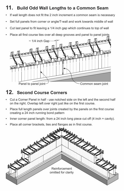
11. Build Odd Wall Lengths to a Common Seam• If wall length does not fit the 2 inch increment a common seam is necessary
• Set full panels from corner or angle/T-wall and work towards middle of wall
• Cut last panel to fit leaving a 1/4 inch gap which continues to top of wall
• Place all first course ties over all deep grooves and panel to panel joints
~ 1/4 inch Gap
12. Second Course Corners• Cut a Corner Panel in half - use notched side on the left and the second half
on the right. Overlap left over right just like on the first course.
• Place full length panels over joints created by the panels on the first course creating a 24 inch running bond pattern
• Inner corner panel length: from a 24 inch long piece cut off (4 inch + cavity).
• Place all corner brackets, ties and flanges as in first course.
Reinforcement omitted for clarity
Panel to panel joint Common seam joint
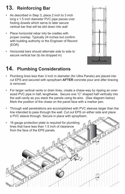
13. Reinforcing Bar• As described in Step 3, place 2 inch to 3 inch
long x 1.5 inch diameter PVC pipe pieces over footing dowels which serve to later secure vertical bar that will be slid down into wall
• Place horizontal rebar into tie cradles with proper overlap. Typically 24 inches but confirm with building authority or the Engineer of Record (EOR)
• Horizontal bars should alternate side to side to secure vertical bar (to be dropped in)
14. Plumbing Considerations• Plumbing lines less than 3 inch in diameter (for Ultra Panels) are placed into
cut EPS and secured with sprayfoam AFTER concrete pour and after bracing is removed.
• For larger vertical vents or drain lines, create a chase-way by ripping an over-sized PVC pipe in half, lengthwise. Secure one “C” shaped half vertically into the wall cavity as you stack the panels using tie-wire. (See diagram below) Mark the position of the chase on the panel face with a marker pen.
• Through wall penetrations are accomplished with PVC sleeves larger than the line intended to pass through the wall. Cut out EPS on either side and place a PVC sleeve through. Secure in place with sprayfoam.
• 16 gauge protection plate is required for plumbing lines that have less than 1.5 inch of clearance from the face of the EPS panels.
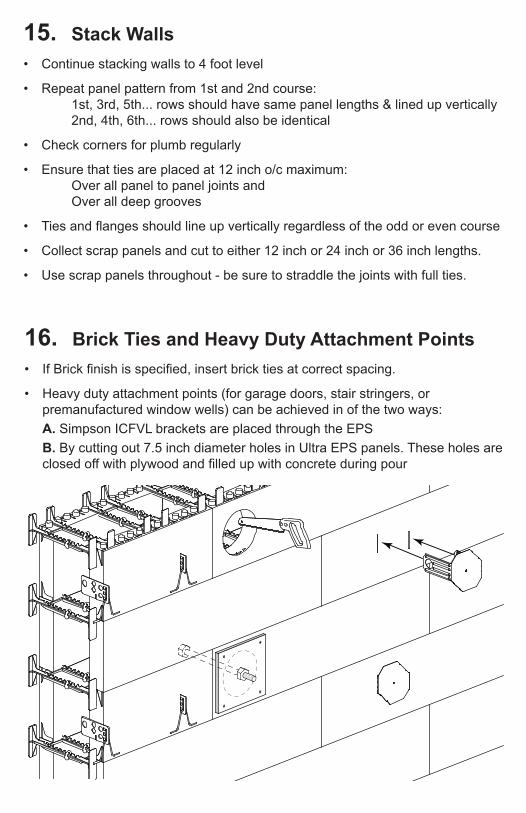
16. Brick Ties and Heavy Duty Attachment Points• If Brick finish is specified, insert brick ties at correct spacing.
• Heavy duty attachment points (for garage doors, stair stringers, or premanufactured window wells) can be achieved in of the two ways:
A. Simpson ICFVL brackets are placed through the EPS
B. By cutting out 7.5 inch diameter holes in Ultra EPS panels. These holes are closed off with plywood and filled up with concrete during pour
15. Stack Walls• Continue stacking walls to 4 foot level
• Repeat panel pattern from 1st and 2nd course: 1st, 3rd, 5th... rows should have same panel lengths & lined up vertically 2nd, 4th, 6th... rows should also be identical
• Check corners for plumb regularly
• Ensure that ties are placed at 12 inch o/c maximum: Over all panel to panel joints and Over all deep grooves
• Ties and flanges should line up vertically regardless of the odd or even course
• Collect scrap panels and cut to either 12 inch or 24 inch or 36 inch lengths.
• Use scrap panels throughout - be sure to straddle the joints with full ties.

18. Plumb, Straight, Square & Level (PSS&L)• At the 4 foot level:
STOP ALL INSTALLATION
• Check all walls for: Plumb Alignment Square Level Accurate Dimensions
• Make adjustments as necessary
17. Window Openings• Determine elevations for window openings
• Prebuild all window bucks with internal bracing to prevent deflection
• Leave space in sill to pour and vibrate
• Set into position and check for level & square
• Secure buck with windlocks & 4 inch screws
• Place a vertical brace either down the center or two at ends for larger openings.
• See the following section regarding bracing installation.
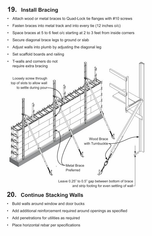
19. Install Bracing• Attach wood or metal braces to Quad-Lock tie flanges with #10 screws
• Fasten braces into metal track and into every tie (12 inches o/c)
• Space braces at 5 to 6 feet o/c starting at 2 to 3 feet from inside corners
• Secure diagonal brace legs to ground or slab
• Adjust walls into plumb by adjusting the diagonal leg
• Set scaffold boards and railing
• T-walls and corners do not require extra bracing
Metal Brace Preferred
Wood Brace with Turnbuckle
20. Continue Stacking Walls• Build walls around window and door bucks
• Add additional reinforcement required around openings as specified
• Add penetrations for utilities as required
• Place horizontal rebar per specifications
Leave 0.25” to 0.5” gap between bottom of brace and strip footing for even settling of wall
Loosely screw through top of slots to allow wall
to settle during pour

21. Top of Wall• Remove interlock knobs from top panels
• Insert 4 Wire Top Ties per panel pair and place metal track over
• Cut and lap track at corners. Secure corner overlap with a self tapping screw.
22. Secure Common Seams• Check corners for plumb and secure
• Cut straps out of 1x4’s to 24 inch lengths
• Screw 1x4’s to plastic ties across the seam with two screws on either end
• Place straps at every row and on both sides of wall
• Close off the gap with low expansion sprayfoam
23. Re-Check PSS&L• Install string line around top course
of panels, space out by 3/4 inches
• Stretch tight and measure gap with 1x4
• Adjust bracing turnbuckles as needed
• Check wall dimensions and plumb at corners
Avoid coinciding track ends
Place 2 Wire Top Ties close to corner 1 foot O/C thereafter
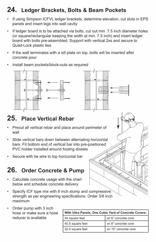
24. Ledger Brackets, Bolts & Beam Pockets• If using Simpson ICFVL ledger brackets, determine elevation, cut slots in EPS
panels and insert legs into wall cavity
• If ledger board is to be attached via bolts, cut out min. 7.5 inch diameter holes (or square/rectangular keeping the width at min. 7.5 inch) and insert ledger board with bolts pre-assembled. Support with vertical 2xs and secure to Quad-Lock plastic ties
• If the wall terminates with a sill plate on top, bolts will be inserted after concrete pour
• Install beam pockets/block-outs as required
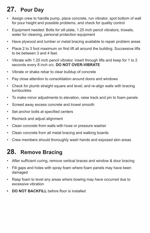
25. Place Vertical Rebar• Precut all vertical rebar and place around perimeter of
wall
• Slide vertical bars down between alternating horizontal bars. Fit bottom end of vertical bar into pre-positioned PVC holder installed around footing dowels
• Secure with tie wire to top horizontal bar
26. Order Concrete & Pump• Calculate concrete usage with the chart
below and schedule concrete delivery
• Specify ICF type mix with 6 inch slump and compressive strength as per engineering specifications. Order 3/8 inch maximum
• Order pump with 3 inch hose or make sure a hose reducer is available
With Ultra Panels, One Cubic Yard of Concrete Covers:54 square feet on 6” concrete core
40.5 square feet on 8” concrete core
32.4 square feet on 10” concrete core
27. Pour Day• Assign crew to handle pump, place concrete, run vibrator, spot bottom of wall
for pour height and possible problems, and check for quality control
• Equipment needed: Bolts for sill plate, 1.25 inch pencil vibrators, trowels, water for cleaning, personal protection equipment
• Have plywood and lumber or metal bracing available to repair problem areas
• Place 2 to 3 foot maximum on first lift all around the building. Successive lifts to be between 3 and 4 feet.
• Vibrate with 1.25 inch pencil vibrator, insert through lifts and keep for 1 to 2 seconds every 8 inch o/c. DO NOT OVER-VIBRATE
• Vibrate or shake rebar to clear buildup of concrete
• Pay close attention to consolidation around doors and windows
• Check for plumb straight square and level; and re-align walls with bracing turnbuckles
• To make minor adjustments to elevation, raise track and pin to foam panels
• Screed away excess concrete and trowel smooth
• Set anchor bolts at specified centers
• Recheck and adjust alignment
• Clean concrete from walls with hose or pressure washer
• Clean concrete from all metal bracing and walking boards
• Crew members should thoroughly wash hands and exposed skin areas
28. Remove Bracing• After sufficient curing, remove vertical braces and window & door bracing
• Fill gaps and holes with spray foam where foam panels may have been damaged
• Rasp foam to level any areas where bowing may have occurred due to excessive vibration
• DO NOT BACKFILL before floor is installed

Damp Proofing • Isolate damp soils from walls by applying a plastic dimpled drainage mat
layer over your ICF walls. Terminate drainage mat at grade level using a termination strip supplied by the drainage mat manufacturer.
• Roll-on emulsion damp proofing products (if compatible with EPS) are acceptable when combined with fabric mesh to span joints between ICF panels.
29. Damp Proofing & Water Proofing• Confirm local code requirements for below-grade water management in your
specific area.
• All below grade walls for occupied spaces MUST be damp proofed at a minimum.
• Potential for saturated soils and hydrostatic pressure MAY trigger a requirement for water proofing.
• A well-designed and constructed footing drain is critical. NEVER route water runoff from roof gutters into footing drains, but rather into separate “tight-line” drains.
INDENT SILL PLATE FROM EXTERIOR OF QUAD-LOCK BY
SHEATHING THICKNESS
PARGING WITH WIRE MESH SCREWED INTO QUAD-LOCK TIE
FLANGES
FINISHING STRIP FOR DRAINAGE/PROTECTION BOARD
QUAD-LOCK ULTRA PANEL
QUAD-LOCK PLASTIC TIE
PRIOR TO BACKFILL SECURE DRAINAGE BOARD TO QUAD-LOCK
PLASTIC TIE FLANGES WITH MANUFACTURER SUPPLIED
WASHERS
PEEL&STICK MAY BE USED AT THIS TRANSITION (SEE WATER
PROOFING DETAIL ON NEXT PAGE

Water Proofing • For self-adhesive (“peel & stick”) membranes, prime the surface of the ICF
with a primer recommended by the membrane manufacturer. Pay attention to temperature and moisture conditions. Clean the footing surface and apply primer to it as well
• Pre-cut self-adhesive membrane to fit VERTICALLY from grade level to footing, plus enough to wrap over edge of footing.
• When primer is adequately dry, immediately apply membrane from top of wall down. Peel away backing paper as you go.
• Quad-Lock recommends that self adhesive membranes be protected against backfill materials.
INDENT SILL PLATE FROM EXTERIOR OF QUAD-LOCK BY
SHEATHING THICKNESS
PARGING WITH WIRE MESH SCREWED INTO QUAD-LOCK TIE
FLANGES
QUAD-LOCK ULTRA PANEL
QUAD-LOCK PLASTIC TIE
REINFORCED CONCRETE COREREINFORCEMENT OMITTED FOR
CLARITY
QUAD-LOCK PEEL&STICK OR EQUIVALENT (3” OVERLAP)
PEEL&STICK OVERLAPS THE STRIP FOOTING

General Checklist
qBuilding lines are snapped on footings; Take into account the EPS panel thickness!
qSteel reinforcing details and specifications checked; Crew members briefed on placement details
q Wall elevations confirmed; Ensure adequate brace & scaffold height.
q Metal track thoroughly checked for secure fastening around entire perimeter.
qEnsure Quad-Lock Full Ties placed 12 inches [305mm] OC, horizontally, vertically and flanges in corners.
q Walls aligned and plumb, checked for square.
q Vertical bracing strong-backs placed at maximum 6 ft. intervals
qBraces secured to each tie flange 12 inches o.c. with fasteners specified by brace manufacturer.
qCommon seams secured with plywood cleats after corners are plumbed. Spray foam remaining gaps.
qWindow and door rough opening sizes confirmed; Double check rough opening dimensions and elevations. Electrical and plumbing supply entry points located and sleeves placed
qFloor elevations and finishes accounted for in placement of door opening elevations
qWindow/Door buck-outs pre-built; Include flashings, water-stops, or any ele-ments left in the wall for prevention of water-intrusion
q Panels secured to internal buck-outs with screws and Wind-Locks (both sides).
qOpenings checked for plumb, straight, square and level; Openings braced hori-zontally and vertically. Window sills open to allow concrete pour & consolidation (Always pour sills first!)
q Door & window lintel dimensions and reinforcement confirmed; Rebar secured
PRIOR TO CONCRETE POUR
qConfirm compressive strength on concrete order (psi or KPa) from plans or engi-neering specifications.
q Concrete aggregate size confirmed: 3/8 inch (10mm)
q Pumping equipment on site with max 3 inch [76mm] hose (preferred)
qConcrete mix ordered at low slump (3 inch to 4 inch [75mm to 100mm]) with water. Add plasticizer to increase slump (recommended minimum slump 6 inch [150mm]) at time of pour).
qConcrete truck delivery spaced to allow time for placement and initial set of 1st lift.
qAdequate labor available for pour. Have working vibrators and cords in place prior to beginning pour.

Quad-Lock Building Systems Ltd.1-888.711.5625
TERMS OF SALE, WARRANTY, DISCLAIMERS
All sales of Quad-Lock Products are subject to the Terms and Conditions of Sale as published at www.quadlock.com/terms at the time of sale and
as amended from time to time without notice at Quad-Lock's sole discretion.