Embed Size (px)
DESCRIPTION
Fitter
Citation preview

CONTENTS
Introduction to Fitting ................................................................................................................................... 1
Supplementary Skills basic maths, etc .......................................................................................................... 3
Supplementary Skills ..................................................................................................................................... 5
Measuring tools ............................................................................................................................................ 8
Measuring tools .......................................................................................................................................... 12
Precision Measurement tools ..................................................................................................................... 16
Marking devices .......................................................................................................................................... 26
Marking devices .......................................................................................................................................... 35
Hand Tools .................................................................................................................................................. 49
Hand Tools .................................................................................................................................................. 56
Cutting tools & operations .......................................................................................................................... 65
Cutting tools & operations .......................................................................................................................... 79
Grinding..................................................................................................................................................... 101
Drilling ....................................................................................................................................................... 106
Drilling ....................................................................................................................................................... 115
Counter Sinking ......................................................................................................................................... 122
Counter Boring .......................................................................................................................................... 127
Reamers .................................................................................................................................................... 135
Reamers .................................................................................................................................................... 141
Hand Tapping & Threading ....................................................................................................................... 149
Hand Tapping & Threading ....................................................................................................................... 160
Limits & Fits ............................................................................................................................................... 161

Limits & Fits ............................................................................................................................................... 168

SYMBOLS USED IN MANUAL
Symbols Implies
Theoretical Session
Practical Session
Revision
Assessment


S k i l l s T r a i n i n g f o r E n g i n e e r i n g & P r o d u c t i o n S y s t e m s P a g e | 1
Introduction to Fitting
Introduction
Fitter trade is one of the important trades in any industry from installation,
commissioning & operations of an industry. Any of the operations in the industry completes
with Fitting job, whether it may be electrical, mechanical like welding, machine operations
etc.
The quality of the work done shows the skill sets of the Fitter completing the work. Fitter is a
important trade for any industry like Electricity, Mechanical & Civil/ Infrastructure
industries. A fitter is needed to assembly or dismantling any machinery, lifting & positioning
of machinery, Cleaning, installation & commissioning of machinery etc.
According to the works done by a fitter the classification is:
a) General Fitter
b) Electrical Fitter
c) Hydraulic Fitter
d) Heavy Machinery Fitter/ Millwright Fitter
e) Erection & Commissioning Fitter
f) Plumbing Fitter
A) General Fitter – This category fitter is related to engineering industry activities & are
considered to be skilled in general operations like working with pumps, motors, gear
box alignment & fitting in dismantling, cleaning & maintenance & also assembling of
the machine parts.
DAY 1: 10.00 AM - 12.00 AM

2 | P a g e
B) Electrical Fitter – A person doing the work for operations & maintenance of
electrical machines like installation, commissioning & operational maintenance is
termed as Electrical Fitter. For eg. Greasing & Coupling changing of a 50. HP motor
is done by an electrical fitter & checking of alignment, changing of armature etc
C) Hydraulic Fitter – The latest trend for power transfer is hydraulic motors, pulleys,
jacks & various other machines etc. Apart for these hydraulic governors are used for
storing of kinetic energy into potential energy in many machines. A hydraulic fitter is
a person who deals with daily operational maintenance of these machines, breakdown
maintenance of the machines & also in some cases installation & commissioning of
these machines
D) Heavy Machine Fitter – Working on high capacity machines like Lathe. Milling
machine, Shaping Machine, CNC Machine for maintenance & operations is known as
Heavy Machine Fitter. He also undertakes with machine maintenance of large
machines such as dumper, excavators pay loaders etc.
E) Erection & Commissioning Fitter – Whenever a new enterprise is setup the erection
machinery has to be done & it has to be handed over for the operations after having
adequate tests being carried out.

S k i l l s T r a i n i n g f o r E n g i n e e r i n g & P r o d u c t i o n S y s t e m s P a g e | 3
Supplementary Skills basic maths, etc
Units of Physical Quantities Fundamental Units
S. No Unit Length (L) Mass (M) Time (T)
1. C G S Centimeter (cm) Gram (gm) Second (sec)
2. F P S Foot (ft.) Pound (lb) Second (sec)
3. M K S Meter (m) Kilogram (Kg) Second (sec)
Derived Units
Like Area & Volume is measured in Square meters & Cubic Meter. Hence
area & volume depends on the derived units of length i.e. meter.
International Units of systems (S I Units)
SI units have 7 fundamental units & two supplementary units & rest are derived units
as shown in table below:
S. No Measuring S I Units
1 Length Meter
2 Mass Kilogram
3 Time Second
4 Intensity of Electric current Ampere
5 Thermodynamic Temperature Kelvin or degree Celsius
6 Quantity of substance Mole
7 Luminous Intensity candela
DAY 1: 12.30 PM - 04.30 PM

P a g e | 4 O n l y F o r P r i v a t e C i r c u l a t i o n
Supplementary Units
Plane Angle Radian
Solid Angle Steradian
Some derived Units are as mentioned below:
S. No Physical units S I Units
1 Area Sq. mtr
2 Volume Cu.mtr
3 Speed m/sec
4 Acceleration m/sq sec
5 Density Kg/cu.m
6 Force Newton
7 Pressure Pascal
8 Energy Joule
9 Power Watt
10 Frequency Hertz

S k i l l s T r a i n i n g f o r E n g i n e e r i n g & P r o d u c t i o n S y s t e m s P a g e | 5
REVISION OF LAST DAY’S LECTURE
Supplementary Skills
Length, area & volume measurements & conversion from one system to another
Mm, cm, meter, inch, feet in length are converted from one system to another
1 inch = 2.54 cm = 25.4 mm
1 ft = 12 inch = 30.48 cm = 304.8 mm
Area Calculation
Areas of Two Dimensional Figures
Triangle: A three sided figure.
Rectangle:
A quadrilateral with four right
angles.
Parallelogram:
A quadrilateral with two pairs
of opposite sides parallel.
Trapezoid:
DAY 2: 10:15 AM - 12.00 PM
DAY 2: 10:00 AM- 10:15 AM

P a g e | 6 O n l y F o r P r i v a t e C i r c u l a t i o n
A quadrilateral with exactly one pair of opposite sides parallel.
Circle:
A set of points all equidistant from a given point -
the center.
Any Regular Polygon:
A figure with all sides and angles
congruent.
Area & Volume of solid objects
Cube
Cuboid
S k i l l s T r a i n i n g f o r E n g i n e e r i n g & P r o d u c t i o n S y s t e m s P a g e | 7
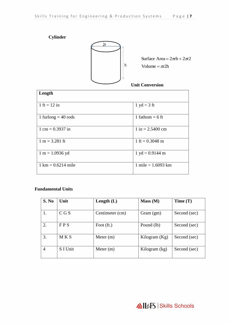
Cylinder
Unit Conversion
Length
1 ft = 12 in 1 yd = 3 ft
1 furlong = 40 rods 1 fathom = 6 ft
1 cm = 0.3937 in 1 in = 2.5400 cm
1 m = 3.281 ft 1 ft = 0.3048 m
1 m = 1.0936 yd 1 yd = 0.9144 m
1 km = 0.6214 mile 1 mile = 1.6093 km
Fundamental Units
S. No Unit Length (L) Mass (M) Time (T)
1. C G S Centimeter (cm) Gram (gm) Second (sec)
2. F P S Foot (ft.) Pound (lb) Second (sec)
3. M K S Meter (m) Kilogram (Kg) Second (sec)
4 S I Unit Meter (m) Kilogram (kg) Second (sec)
r22 rh 2 Area Surface
r2h Volume

P a g e | 8 O n l y F o r P r i v a t e C i r c u l a t i o n
REVISION OF LAST DAY’S LECTURE
Measuring tools
Measurement: Determining the size of a component in terms of
standard units is called measurement. For example, linear measurement
applies to measurement of length, diameter, height, thickness, etc.
covering both external and internal features.
When any measurement is carried out the magnitude of same quantity.
This fixed predetermined magnitude is called unit of the quantity.
SYSTEMS OF UNITS
British System : It is called foot, pound and second (fps) system.
Here foot, pound and second are the fundamental units of length,
mass and time.
Metric System: Here metre, kilogram and second (MKS) are the
fundamental units of length, mass and time.
S.I. Units: It is the refinement of the metric system and is now
adopted widely through out the world. The seven basic units in this
system are given in the following table.
Quantity Unit Symbol
Length
Mass
Time
Electric Current
Metre
Kilogram
Second
Ampere
M
Kg
S
A
DAY 3: 10:15 AM - 12.00 PM
DAY 3: 10:00 AM- 10:15 AM
S k i l l s T r a i n i n g f o r E n g i n e e r i n g & P r o d u c t i o n S y s t e m s P a g e | 9
Thermodynamic
temperature
Luminous intensity
Amount of substance
Kelvin
Candela
Mole
K
Cd
Mol
TYPES OF MEASURING TOOLS
Fixed Type: Steel rule, Plug Gauge, feeler gauge etc.
Adjustable Type: Caliper, Surface Gauge, micrometer etc.
Direct Reading: Steel rule, Vernier Caliper, micrometer etc.
Indirect Reading: Divider, calipers, surface gauge etc.
Non-reading: Snap gauge, plug gauge, ring gauge etc.
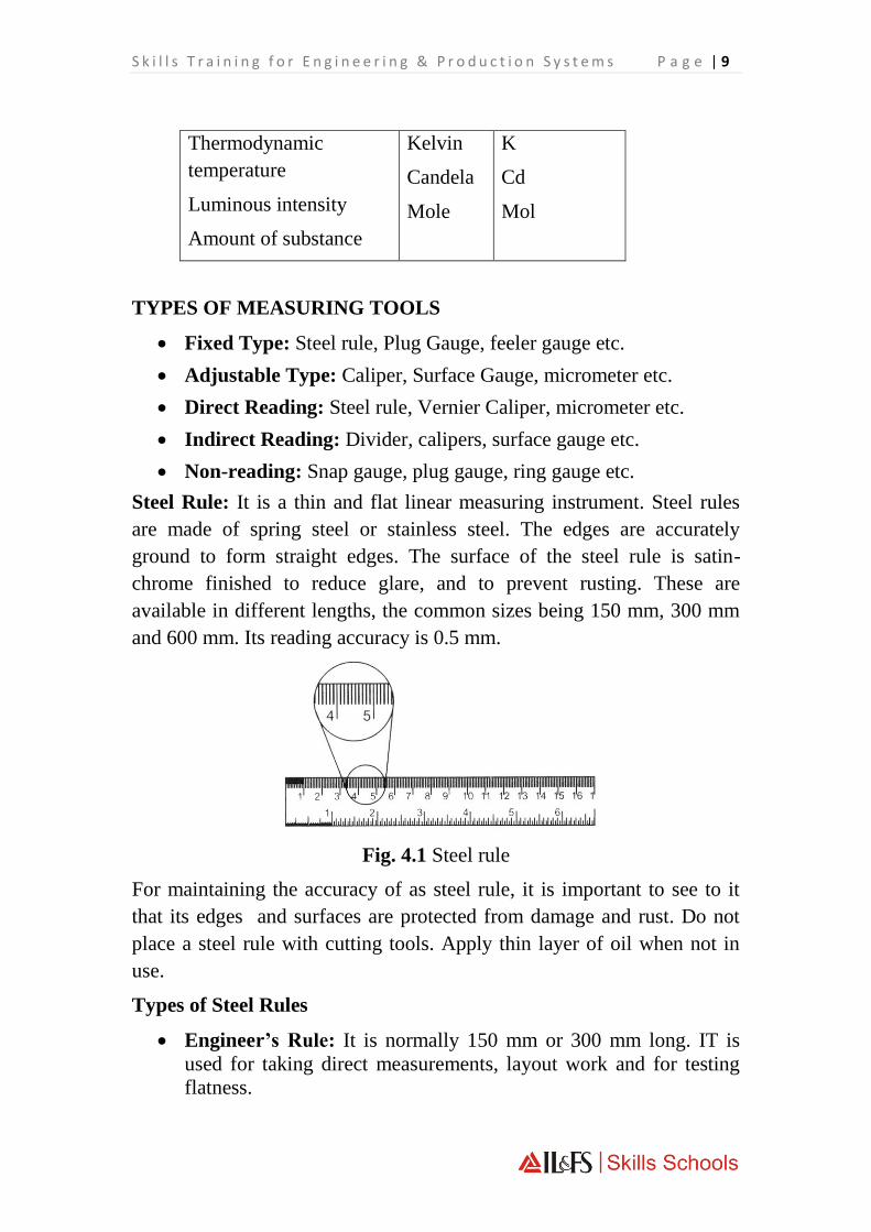
Steel Rule: It is a thin and flat linear measuring instrument. Steel rules
are made of spring steel or stainless steel. The edges are accurately
ground to form straight edges. The surface of the steel rule is satin-
chrome finished to reduce glare, and to prevent rusting. These are
available in different lengths, the common sizes being 150 mm, 300 mm
and 600 mm. Its reading accuracy is 0.5 mm.
Fig. 4.1 Steel rule
For maintaining the accuracy of as steel rule, it is important to see to it
that its edges and surfaces are protected from damage and rust. Do not
place a steel rule with cutting tools. Apply thin layer of oil when not in
use.
Types of Steel Rules
Engineer’s Rule: It is normally 150 mm or 300 mm long. IT is
used for taking direct measurements, layout work and for testing
flatness.

P a g e | 10 O n l y F o r P r i v a t e C i r c u l a t i o n
Folding Rule: It is normally 300 mm long with 2 folds. It can be
conveniently carried.
Flexible Rule: It is thinner and narrower than a plain steel rule.
Since it is flexible it can be conveniently used to measure curved
surfaces.
Hook Rule: It has a hook attached to one end. This hook is found
to be very useful for taking measurement in flanges or through
hubs of pulleys where the measuring edge cannot be seen by the
user.
Short Rule: This is a set of small rules used to facilitate
measurements in small spaces where other types of rules are
inconvenient. The lengths of this rule are 10, 15, 20, 25 mm, and so
on.
Shrink Rule: It is used for laying out casting pattern and core
boxes. It is made oversize to allow for contraction of metals and
graduated to distribute the extra length uniformly throughout the
rule. So the actual dimension in an ordinary rule and this rule will

S k i l l s T r a i n i n g f o r E n g i n e e r i n g & P r o d u c t i o n S y s t e m s P a g e | 11
Fig. 4.2 Types of rules
The following types of care should be taken while using rules:
Use the rule for measurement only
Don’t use it as a screw driver, lever or scraper.
Keep the rule slightly oiled. It will prevent rusting.
Store the rule away (when not required) flat and fully supported, or
suspended from the hole provided.

P a g e | 12 O n l y F o r P r i v a t e C i r c u l a t i o n
Measuring tools (Contd.)
CALIPERS:
Calipers are simple measuring instrument used to transfer measurement
from a steel rule to objects, and vice versa. The commonly used calipers
are:
Firm Joint Calipers: It has both legs pivoted at other end. To make
measurement of a work piece, the caliper is opened roughly to the
required size. Fine setting done by tapping the caliper lightly on a wood
surface.
Spring Join Calipers: It has legs assembled by means of a pivot loaded
with a spring. For opening and closing the caliper legs, a screw and nut
are provided. This type of calipers has the advantage of quick setting.
The size of a caliper is specified by the length, which is the distance
between the pivot centre and the tip of the leg. The accuracy of the
measurement taken depends very much on the sense of ‘feel’ while
measuring the job,
DAY 3: 12.30 PM- 04.30 PM

S k i l l s T r a i n i n g f o r E n g i n e e r i n g & P r o d u c t i o n S y s t e m s P a g e | 13
Outside and Inside Calipers: Outside and inside calipers are
differentiated by the shape of legs. Calipers
The Rule as a Straight edge: The edges of a steel rule are ground flat
and may therefore be used as straight edges to the flatness of work pieces.
The edge of a rule should be placed on the work surface which is then
help up to the light. Inaccuracies as small as 0.02 mm may easily be seen
by this method.
Transfer Caliper: This type is available both as outside and inside
calipers. The transfer calipers are provided with a false leg, which is
temporarily fastened to one of the legs, after setting this leg it may
be moved away from the false leg, the calipers withdrawn and the leg
again placed in contact with the false leg and locked in position by a set
screw.
Jenny Caliper: Jenny calipers have one straight pointed leg and the other
leg turned inward. They are used for marking lines parallel to straight
edges and for transferring dimensions. Jenny calipers are used for finding
the centre of a rod. Arcs of circles are drawn from different points on the
circumference, thus fixing the approximate centre of the rod. Jenny
calipers are sometimes called odd-legs, leg and point or hermaphrodite
calipers.

P a g e | 14 O n l y F o r P r i v a t e C i r c u l a t i o n
(a) Scribing a line parallel to an edge with a jenny caliper (b) using a
jenny caliper to dind the centre of round stock
The measurement is transferred by using a steel rule
Try Square: It is precision instrument, which is used to check squareness
of a surface. It consists of a stock and blade. The blade is fixed to the
stock at 90°. It is
Types : Generally following try squares are used :
1. Fixed Try square: Its blade is fixed with the stock by riveting.
This type of try square is used for general work where extreme
accuracy is required.
2. Adjustable Try square: Its blade can be adjusted on the stock
with the help of a pin and knurled nut. It is more useful because
squareness of the job can be checked at either side of the stock. It
should not be used where higher accuracy is required.
Checking Try square for Accuracy: The accuracy of try square can
be checked by the following method s:
1. The accuracy of try square can be checked by a Mater try square.
This method is used where more accuracy is required.

S k i l l s T r a i n i n g f o r E n g i n e e r i n g & P r o d u c t i o n S y s t e m s P a g e | 15
2. The accuracy of try square can be cheeked by angle plate and
straight edge. Clamp the straight edge on an angle plate and put it
on surface plate. Place the stock of try square on the surface plate
with edge of the blade against the outer edge of the straight edge.
Then clamp firmly the straight edge in this position, shift the try
square blade and try against the inner edge of the straight edge. If
the blade fails to align against it then the try square is not correct
and it should not be used.
3. The accuracy of try square can be checked with surface plate. Place
the try square on a surface plate. Mark line along the side of the
blade. Turn the stock of try square in opposite direction as shown
in Fig. 4.19 and mark another line along the side of the blade. If
both lines are coincided or parallel to each other, it is considered
that try square is true. If both lines are not parallel or coincided to
one another, then try square not true and it should not be used.
STRAIGHT EDGE
Straight edges are made of hardened steel. It’s both edges are finished
level and parallel with one edge usually beveled. As shown in Fig.
4.20 ‘A’ is a general purpose straight edge, ‘B’ is a toolmaker’s
straight edge and ‘C’ is a cast iron straight edge.
Fig. 4.20 Straight Edges
Straight edges are used for checking the straightness of an edge of a
work-piece an also for checking surface uniformity.

P a g e | 16 O n l y F o r P r i v a t e C i r c u l a t i o n
REVISION OF LAST DAY’S LECTURE
Precision Measurement tools
Outside Micrometer: External micrometers are used to measure
external dimension like shaft diameters, thicknesses of plats, flats etc.
The parts of an external micrometer are:
Frame: It is made of drop-forged steel or malleable cast iron.
All other parts of th e micrometer are attached to this.
Anvil: The projected portion out of the frame for a distance of
at least 3 mm is called anvil. It is one of the measuring faces. It
is made of alloy steel and finished to a perfectly flat surface.
Spindle: The spindle acts and grips the job against the anvil.
The threaded mechanism allows for the forward and backward
movement of the spindle.
Barrel: It is fixed on the frame. The datum line and graduations
are marked on this.
Thimble: It is a tubular cover attached with the spindle and
moves with the spindle. The thimble has a beveled edge, and
divided into 50 equal parts. Every 5th part is numbered as 0, 5,
10….., 45.
DAY 4: 10:15 AM - 12.00 PM
DAY 4: 10:00 AM- 10:15 AM

S k i l l s T r a i n i n g f o r E n g i n e e r i n g & P r o d u c t i o n S y s t e m s P a g e | 17
Outside micrometer
Ratchet Stop: This is an extension to the thimble. In ensures a
uniform pressure between the measuring surfaces.
Spindle Lock Nut: It is used to lock the spindle at a desired
position.
Working Principle of Micrometer: The micrometer works on the
principle of screw and nut. The longitudinal movement of the spindle
during one revolution is equal to the pitch of the screw. The
movement of the spindle to the distance of the pitch or its fractions
can be accurately measured on the barrel and thimble.
In metric micrometers the pitch of the spindle thread is 0.5 mm.
Thereby, in one revolution of the thimble, the spindle advances by 0.5
mm. On the barrel, a 25 mm long datum is marked. This line is further
graduated to mm and half mm. The circumference of the bevel edge of
the thimble is graduated into 50 divisions. The movement of one
division of the thimble is, therefore, 0.01 mm. The accuracy or least
count of a metric outside micrometer is 0.01 mm.

P a g e | 18 O n l y F o r P r i v a t e C i r c u l a t i o n
Reading a Micrometer: To take a reading from a micrometer you
need to observe three things:
Major divisions (i.e. number of whole mm)
Major divisions (i.e. number of half mm)
Thimble divisions (against datum line)
The measurement shown in figure would be
Major division 17.00 mm
Minor division 0.50 mm
Thimble division 0.18 mm
Reading 17.68 mm
Reading
Zero Error of a micrometer: Move the spindle of the micrometer
until is not aligned with the zero of the datum line of the sleeve, the
micrometer is said to have zero error. If the micrometer reads plus, it
has minus zero error. The error will have to be subtracted from the
actual reading. If the micrometer reads minus, it has plus zero error.
The error will have to be added to the actual reading.

S k i l l s T r a i n i n g f o r E n g i n e e r i n g & P r o d u c t i o n S y s t e m s P a g e | 19
Types of Micrometer
A. Inside Micrometer: Inside micrometers are used to obtain direct
measurement of internal sizes, such as diameters of holes, or the
distance between two parallel surfaces. The principle of
measurement is the same as that of external micrometer. The
measuring surfaces are hardened and ground to a radius to secure
accurate measurement and the movable jaw can be tightened when
desired to retain the setting of the instrument. There are inside
micrometers available in various sizes with measuring range from
25 mm to 50 mm and 50 mm to 150 mm. The accuracy in reading
is 0.01 mm.
Fig. 5.3 (a) Inside micrometer
DAY 4: 12.30 PM- 04.30 PM

P a g e | 20 O n l y F o r P r i v a t e C i r c u l a t i o n
Fig. 5.3 (b) Measurement with inside micrometer
B. Screw Thread Micrometer: It is an instrument sued for
measuring pitch diameter of screw threads. It consists of the same
parts as the outside micrometer except that the movable spindle is
pointed and the end of the anvil is of the same from as the screw
thread to the measured.
C. Tube Micrometer: This micrometer is used for measuring the wall
thickness of tubes, pipes, etc. Its anvil has a spherical shape. For
measuring the thickness, the anvil is inserted inside the tube, the
wall of the tube shall sit freely on the anvil, the spindle being flat at
the end as in the normal case contacts the wall from outside.
D. Rolling Mill Micrometer: This type of micrometer is primarily
designed for gauging the thickness of sheets while rolling so as to
obtain an accurate measurement away from the edge of the sheet.
But it is also used for other measurements which require a deep
throat to enter.

S k i l l s T r a i n i n g f o r E n g i n e e r i n g & P r o d u c t i o n S y s t e m s P a g e | 21
E. Electronic Micrometer: It is a handy instrument, which allows
taking measurements with least count of 1 micron (0.001 mm). The
spindle is opened with the help of a push button and slide over the
job. The size appears on the dial which can be easily read. Such
micrometers are made in different ranges.

P a g e | 22 O n l y F o r P r i v a t e C i r c u l a t i o n
REVISION OF LAST 4 DAY’S LECTURE
Vernier Caliper: When measurements are to be made to a greater
accuracy than can be expected from a steel rule but not to the accuracy
afforded by a micrometer then a vernier caliper is used. It measures to an
accuracy of 0.02 mm. It scomponents are fixed jaw, movable jaw, main
scale, vernier scale, clamp, clamp screws and adjusting nut.
Each major division on the main scale is 1 mm and minor division 0.5
mm. 25 divisions on the vernier scale are equal to 24 divisions (each of
0.5 mm) of the main scale. Therefore the length of each vernier scale is
0.5 of 24/25 or 0.48 mm, an dsince the main scale divisions are 0.5 mm
the difference between them is 0.02 mm.
The position of the vernier zero mark
The vernier division, which coincides with a division on the main
scale.
DAY 5: 12.30 PM- 04.30 PM
DAY 5: 10:00 AM- 12:00 PM

S k i l l s T r a i n i n g f o r E n g i n e e r i n g & P r o d u c t i o n S y s t e m s P a g e | 23
Main parts of a vernier caliper
Magnifying Glass: It is a glass fitted in a frame with handle. It is used
when reading a Vernier Caliper which magnifies the Vernier divisions.
Causes of False Reading:
(a) Vernier caliper is faulty.
(b) Not cleaning the job and measuring faces of vernier caliper.
(c) Wrong way of holding a vernier caliper and taking the reading
incorrectly.
(d) Measuring the job when it is in movement.
(e) Giving too much or too less pressure when measuring
(f) When there is a difference in temperature between the job and a
vernier caliper.
Advantages of a Vernier Caliper over a Micrometer:
(a) Vernier caliper is a multipurpose instrument which can be used to
measure outside, inside and depth measurements but micrometer is
not a multipurpose instrument.
(b) Different sizes of a job can be measured with one vernier caliper
but a number of micrometers are required for different sizes of
jobs.

P a g e | 24 O n l y F o r P r i v a t e C i r c u l a t i o n
DIAL CALIPERS
Dial caliper is a modern instrument which incorporates all the features of
a vernier caliper except a dial in place of vernier scale, a thumb roller and
a rack (Fig. 5.16). It is used to measure the outside, inside and depth
measurements within the accuracy of 0.02 mm.
VERNIER BEVEL PROTACTOR
It is a precision angle-measuring instrument used fo layout and checking
of an angle with an accuracy of 5 minutes (one twelfth of a degree). It
consists of a graduated disc with a fixed stock and an adjustable blade.
The disc is graduated is degrees from 0° to 90° or 0° to 180° each way
and backward over its full length. It can turn through any angle around
the circle and can be clamped by a knurled nut in any desired position.
The vernier extends to 23° left and right of the zero line. The angle of 23°
is divided into 12 equal divisions. Each division is thus equal to
23 111 1 55'
12 12
Suppose the zero marking of vernier and main scale coincide, in that case
he first graduation
line of the vernier and the nearest graduation line of the main scale. Such
In order to maintain the vernier bevel protractor in good condition,
always keep the sliding parts free from grit, dirt or abrasive particles.
Apply instrument oil and keep in a box, when not in use.
MEASURING ERRORS
When we measure a work piece, measuring errors may take place. The
error in measuring depends on the skill of the person taking measurement
and the inaccuracy of the measuring instrument. Generally following
measuring errors are noticed.
1. Geometrical Errors: These errors can be subdivided into the
following:
(a) Micro-geometrical Errors : These errors occur due to
surface roughness. When measuring, the tip could drop in
profile recess and gives a faulty reading.

S k i l l s T r a i n i n g f o r E n g i n e e r i n g & P r o d u c t i o n S y s t e m s P a g e | 25
Micro-geometrical errors
(b) Macro-geometrical Errors: These errors occur when a
cylinder is tapered or out or found. This type of error can be
detected by using three point measurements i.e. by placing
the shaft on a ‘V’ block. See Fig. 5.24
2. Contact Errors: The contact errors generally occur between the
measuring tip and the job being measured. In order to eliminate
these errors, the measuring instruments must be cleaned.

P a g e | 26 O n l y F o r P r i v a t e C i r c u l a t i o n
REVISION OF LAST DAY’S LECTURE
Marking devices
The most important step in the marking of a machine part and in a
particular fitting operation is the marking or layout of guidelines on the
metal before machining or cutting by hand tools.
PURPOSE OF MARKING
• To ensure that the correct amount of metal is removed from the
various faces so that the correct shape is produced.
• To provide lines which will serve as a guide indicating
that a correct size has been reached.
MARKING MEDIA
As metal is a hard material, marked lines are not shown clearly. It is due
to this reason that a marking medium is applied on metal when laying
out. A marking media is, thus a substance, which is applied on the
surface to be marked to distinct the marked lines clearly. Some of the
commonly used marking media are — chalk, layout dye, copper sulphate,
whitewash.
DAY 6: 10:15 AM - 12.00 PM
DAY 6: 10:00 AM- 10:15 AM

S k i l l s T r a i n i n g f o r E n g i n e e r i n g & P r o d u c t i o n S y s t e m s P a g e | 27
Methods of Marking : Generally following marking methods are used:
1. Datum Line Method : In this method a base line is marked first
which is called as datum line. Further lines are drawn from this pre-
marked datum line. This method is used where the adjacent sides of
a job are finished at right angle.
2. Centre Line Method : This method of marking is used on odd
shaped job. An approximate centre line is marked first and other
lines are marked with reference to this pre-marked centre line,
3. Marking by Template : In this method a template is used for
marking which is made from thin metal sheet according to shape.
Identical parts are marked with this method of marking.
4. Marking of Centre on Round Rod End :
(i) By Jenny Caliper : Draw four arcs by opening jenny caliper
above or below the radius and find out the centre.
(ii) By Surface Gauge or Vernier Height Gauge : Place the job
on V-Block and set the surface gauge or Vernier height gauge
above or below the centre of job and mark four lines from
different four positions to make a square. Draw diagonal lines.
The intersecting point is the centre of round rod end.
(iii) By Centre Head of Combination Set : Place the centre head
on the job and mark a line and turn it to mark another line at
right angle. The intersecting point is the centre of round rod
end.

P a g e | 28 O n l y F o r P r i v a t e C i r c u l a t i o n
(iv) By Bell Punch: Place the bell punch on the round rod end and
strike its head with light blow of hammer to find the centre.
HINTS TO BE NOTED WHILE MARKING
1. Study the workpiece drawing carefully.
2. Determine datum features from which all dimensions
will be layed out.
3. Calculate all workpiece-dimensions and allowances carefully.
4. Check for proper application of marking media on the
surface of workpiece.
5. Mark first straight horizontal, vertical and inclined ones, and then
circles, arcs, curves etc.
6. Punch the marked lines with proper distance,
7. After completion of marking clean the job and tools used for this
purpose.
EQUIPMENT AND INSTRUMENTS
The equipment and instruments used for marking described below :
SURFACE PLATE: It is a large accurately machined surface. It is made
of cast iron, granite or ceramic. Some surface plates are lapped flat to an
accuracy with 0.0025 mm. It is used to test the flatness of other surfaces
or to provide a truly flat datum surface in marking off work for
machining. It is also used for the inspection of gauges, jigs and fixtures.

S k i l l s T r a i n i n g f o r E n g i n e e r i n g & P r o d u c t i o n S y s t e m s P a g e | 29
In order to take proper care of surface plate and for its proper
maintenance:
• The top of the surface plate should be kept clean and free from
dust, rust and burrs.
• The surface plate should be supported on three legs to avoid
rocking and twisting which is liable to occur if it is supported on
four legs.
• The surface plate must be wiped clean and smeared with grease or
oil after use.
• No heavy object should be dropped on the surface plate.
MARKING TABLE : It is made of close-grained cast iron and is given
special treatment so that it does not change its shape after use. Its top is
machined flat, it consists of an accurate, planed flat-surface, planed long
edges and a metal stand.

P a g e | 30 O n l y F o r P r i v a t e C i r c u l a t i o n
The marking table provides a 'reference plane' on which the work and the
marking-out tools stand. The work being marked must be placed at 90° to
this reference plane. The marking table should be protected by a well-
fitting wooden cover, when not in use.
SCRIBER: It is a pointed tool made of hardened tool steel for making a
incised mark on metal. It may be straight or bent. It has a single conical
point (included angle usually 15°) and knurled body. The scriber must be
held at an angle, inclined towards the direction of movement and moved

S k i l l s T r a i n i n g f o r E n g i n e e r i n g & P r o d u c t i o n S y s t e m s P a g e | 31
along the rule using firm and constant pressure. It should be kept sharp.
Scriber points are very sharp, and they are to be handled very carefully.
Do not put the scriber in your pocket. Place a cork on the point when not
in use to prevent accidents.
DIVIDER: It is an instrument used for marking out circles, arcs and
other geometrical constructions. It is also used to transfer dimensions. It
is made of tool steel with points hardened and tempered. A divider is
classified according to the maximum 'opening' between the two points.
Uses :
• To measure distance between points.
To transfer measurements directly from a steel rule.
See Fig. 2.6(a).

P a g e | 32 O n l y F o r P r i v a t e C i r c u l a t i o n
• To scribe circles and arcs on metal jobs. See Fig. 2.6 (b).
TRAMMEL: Trammel points are attached to a bar of a length to suit
the job. They are used to draw arcs and circles of greater radius that
can be drawn with dividers.
HERMAPHRODITE CALIPER: The hermaphrodite caliper is
generally used to locate the centers of a round work or work which has
been cast and is not quite round. It has one bent leg and one straight leg
which contains a sharp point used to scribe layout lines. Hermaphrodite
calipers may also be used to scribe lines parallel with a machined edge
or shoulder. When setting this tool to a size, place the bent leg on the
end of a rule and adjust the other leg until the scriber point is at the

S k i l l s T r a i n i n g f o r E n g i n e e r i n g & P r o d u c t i o n S y s t e m s P a g e | 33
desired graduation. Care should be taken not to loosen the nut and screw
attachment, which holds the scriber point in position.
Uses :
• It is used to mark lines parallel to edges inside and outside. See Fig.
2.8.
Fig. 2.8. Making lines parallel to edge It is used to locate the centre of
round bars. See Fig. 2.9.
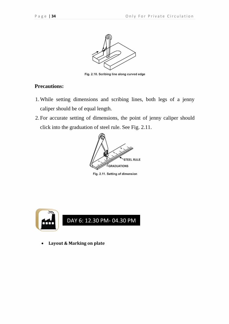
It can also be used for scribing lines along curved edges. See
Fig. 2.10.
P a g e | 34 O n l y F o r P r i v a t e C i r c u l a t i o n
Precautions:
1. While setting dimensions and scribing lines, both legs of a jenny
caliper should be of equal length.
2. For accurate setting of dimensions, the point of jenny caliper should
click into the graduation of steel rule. See Fig. 2.11.
Layout & Marking on plate
DAY 6: 12.30 PM- 04.30 PM

S k i l l s T r a i n i n g f o r E n g i n e e r i n g & P r o d u c t i o n S y s t e m s P a g e | 35
Theory Assessment I
Marking devices (Contd.)
PRICK PUNCH: A prick punch is a layout instrument made of tool
steel, about 100 mm to 150 mm long, with both ends hardened and
tempered. Its point is ground to an angle of from 30° to 60°. It is used to
make small indentations along layout lines, to mark centers for drilled
holes, and also centers for divider points. Punch marks are sometimes
called witness marks, because the indentations will still remain if the
layout lines should be rubbed off the surface of the work.
DAY 7: 10.30 AM - 12.00 PM
DAY 7: 10:00 AM- 10.30 AM
P a g e | 36 O n l y F o r P r i v a t e C i r c u l a t i o n
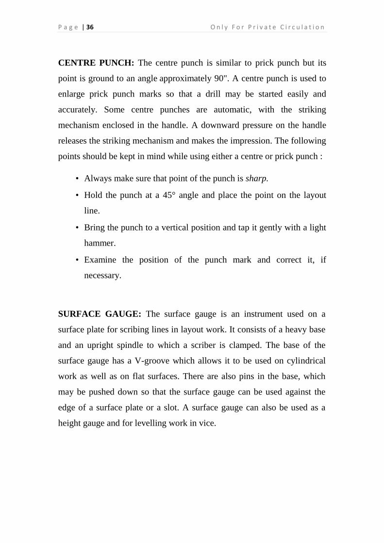
CENTRE PUNCH: The centre punch is similar to prick punch but its
point is ground to an angle approximately 90". A centre punch is used to
enlarge prick punch marks so that a drill may be started easily and
accurately. Some centre punches are automatic, with the striking
mechanism enclosed in the handle. A downward pressure on the handle
releases the striking mechanism and makes the impression. The following
points should be kept in mind while using either a centre or prick punch :
• Always make sure that point of the punch is sharp.
• Hold the punch at a 45° angle and place the point on the layout
line.
• Bring the punch to a vertical position and tap it gently with a light
hammer.
• Examine the position of the punch mark and correct it, if
necessary.
SURFACE GAUGE: The surface gauge is an instrument used on a
surface plate for scribing lines in layout work. It consists of a heavy base
and an upright spindle to which a scriber is clamped. The base of the
surface gauge has a V-groove which allows it to be used on cylindrical
work as well as on flat surfaces. There are also pins in the base, which
may be pushed down so that the surface gauge can be used against the
edge of a surface plate or a slot. A surface gauge can also be used as a
height gauge and for levelling work in vice.

S k i l l s T r a i n i n g f o r E n g i n e e r i n g & P r o d u c t i o n S y s t e m s P a g e | 37
Surface gauges are of two types :
Fixed Type Surface Gauge: It consists of a heavy flat base and a fixed
spindle, fixed upright, to which a scriber is attached with a snug and a
clamp nut.
Universal Surface gauge: It has the following additional features:
(i) The spindle can be set to any position,
(ii) Fine adjustments can be made quickly. (iii) Can also be used on
cylindrical surfaces.

P a g e | 38 O n l y F o r P r i v a t e C i r c u l a t i o n
The following types of care should be taken of the surface gauge:
• Do not use it on unlevelled surface.
• Clean it properly before using it.
• Scriber point must be safely guarded.
MARKING METHOD
1. Clean the surface plate.
2. Select surface gauge, angle plate or V-block and steel rule
according to the size of job. If possible use rule in square
head of combination set.
3. Hold the steel rule by supporting it with the angle plate.

S k i l l s T r a i n i n g f o r E n g i n e e r i n g & P r o d u c t i o n S y s t e m s P a g e | 39
4.
5. Loosen the clamping nut of scriber snug and adjust the
scriber approximately and tighten it.
6. Use fine adjusting screw to take correct measurement.
7. Remove steel rule and place work piece and mark lines on it.
While marking, odd shaped jobs should be clamped on angle
plate and round jobs should be supported on V-block.
'V'-BLOCKS: 'V'-blocks are generally made of hardened steel or
cast iron and are available in a wide range of sizes. They are used
when laying out or drilling round work. Usually they come in pairs
and have an accurate 90° V-shaped slot machined in the top and
bottom. A U-shaped clamp is generally supplied with V-blocks in
order to hold the work securely.

P a g e | 40 O n l y F o r P r i v a t e C i r c u l a t i o n
Specification
1. 'V' blocks are designated by the nominal size (length) and the
minimum and the maximum diameter of the job capable of being
clamped, the grade and the number as per B.I.S. standard e.g., 'V'
Block 50/5-40 A-IS 2949.
2. Matched pair 'V' Blocks are indicated by the letter 'M' e.g., 'V'
Block M 50/5-40 A-IS 2949.
3. For 'V' Blocks supplied with clamps are indicated 'With Clamp'
e.g., 'V' Block with clamp 50/5-40 A-IS 2949.
Material: 'B' grade 'V Blocks are made from closed grain cast iron
and 'A' grade 'V' Blocks are made from high quality steel.
Grade: 'V' Blocks are found in grade 'A' and 'B' 'V Blocks of grade
'A' are more accurate and are found only upto 100 mm length. 'V'
Blocks of grade 'B' are used for general work and are found upto 500
mm length.
Types: There are four types of 'V Blocks as per Indian Standard
(B.I.S).
1. Single Level Single Groove 'V' Block: It has only one 'V'
groove and has single rectangular slots on either sides for
accommodating the holding clamps.
2. Single Level Double groove 'V' Block: It has one 'V' groove and
has two rectangular slots on either side for accommodating
holding clamps in two positions.

S k i l l s T r a i n i n g f o r E n g i n e e r i n g & P r o d u c t i o n S y s t e m s P a g e | 41
3. Double Level Single Groove 'V' Block: It has two 'V'
grooves on the top and bottom and has a single rectangular
slot on either side for accommodating holding clamps.
4. Matched Pair 'V' Block: These types of 'V' Blocks are found
in pairs having same size and same grade of accuracy. These
are used for supporting long shafts. See Fig. 2.19.
TESTING ACCURACY OF 'V' BLOCKS
Set up the pair of 'V' Blocks on a surface plate. Place a round tested bar
on them and test both the ends by a dial test indicator. If both ends have
the same reading, the 'V' blocks may be considered as true.
PRECAUTIONS
1. Clean 'V Block before and after use.

P a g e | 42 O n l y F o r P r i v a t e C i r c u l a t i o n
2. Avoid scratching on 'V Blocks.
3. Apply thin layer of oil or grease when it is not in use.
4. Use same size 'V Blocks for supporting long shafts.
ANGLE PLATES: An angle plate is a precision L-shaped tool made of
cast iron or hardened steel, machined to an accurate 90° angle with all
working
surfaces and edges ground square and parallel. Angle plates are used to
hold work parallel and at right angles to a surface. C-clamps are generally
used to fasten work to an angle plate; however, some angle plates are
provided
with slots and tapped holes for this purpose.
Size: Angle plates are found in different sizes which are indicated by
numbers. Generally size nos. 1 to 10 are available. The size no. 1 has 125
mm length, 75 mm breadth and 100 mm height.
Grade: Angle plates are found in grade-1 and grade-2. The grade-1 angle
plates are more accurate and used for tool room work. The grade-2 angle
plates are generally used for machine shop work.
Specification: Angle plates are specified by size no., grade and Indian
standard (BIS) no. e.g., Angle plate size no. 2, Grade-2 -IS-623.
Types: Generally following angle plates are used :
1. Plain Solid Angle Plate: It has two plane surfaces at right angle to
each other which are comparatively smaller in size. It is used for
supporting workpieces during layout work. See Fig. 2.20(a).

S k i l l s T r a i n i n g f o r E n g i n e e r i n g & P r o d u c t i o n S y s t e m s P a g e | 43
2. Slotted Angle Plate: Both the planes of this angle plate have slots.
It is bigger in size than the plain solid angle plate. The slots of this
angle plate can be used for accommodating clamping bolts.
3. Swivel Angle Plate: It’s both plane surfaces can be tilted at an
angle as per graduations marked on it and locked in position by a
bolt and nut provided for this purpose.
4. Box Angle Plate: It has all the faces square to each other. Its all
the faces have slots for accommodating clamping bolts. After
setting the job it can be turned over with the box which enables it
for further marking out or machining.
5. BOX SQUARE : The box square is used to draw lines on the
surface of round stock parallel to the axis such as when setting out
keyways and spines

P a g e | 44 O n l y F o r P r i v a t e C i r c u l a t i o n
PARALLELS: Parallels are square or rectangular led steel bars whose
surfaces have been ground square and parallel. They are made in pairs
and are used in layout work to raise the work to a suitable height and
provide a solid seat.
The following types of care should be taken of the parallels:
• Always keep them clean.
• Avoid dropping them on the working surface.
• After using they apply oil or grease.
• Do not mix them with cutting tools.
COMBINATION SET: The combination set is used both for marking
out and measuring. It is generally made of alloy steel. The measuring

S k i l l s T r a i n i n g f o r E n g i n e e r i n g & P r o d u c t i o n S y s t e m s P a g e | 45
faces are highly ground. The set consists of four principle parts: steel
rule, square head, bevel protractor, and centre head.
• Steel Rule: The steel rule or blade may be fitted to the centre head,
the bevel protractor, or to the square head. Sometimes it is used
separately as a straight edge or for measuring. Metric combination
set rules is usually graduated in millimetres and half millimetres.
• Square Head: The square head or combination square is used to
lay out lines parallel and at right angles to an edge. It may also be
used as a depth gauge or for checking 45° and 90° angles. The
square head can be moved along to any position on the rule.
• Protractor Head: The protractor head is used to lay out and check
angles within an accuracy of 1°. The spirit level attached to this is
useful for setting jobs in a horizontal plane.
• Centre Head: The centre head forms a centre square when
clamped to the rule. It can be used for locating centres of round,
square, and octagonal stock.
The following types of care should be taken of the combination set:
• Handle with extreme care to ensure the working surfaces do not get
marked
• When not in use, oil it and store away carefully.
• Do not mix with other cutting tools.
• Use only one head at a time. Remove the others and keep them
away carefully.

P a g e | 46 O n l y F o r P r i v a t e C i r c u l a t i o n
BEVEL SQUARE: This instrument is used for marking lines at a given
angle to an edge or for checking the angular accuracy of inclined
surfaces. It consists of a blade, stock and knurled nut, usually made of
carbon steel with ground
parallel edges. Its shape varies slightly but it has a blade that can be
swiveled through 360° and locked in any desired position.

S k i l l s T r a i n i n g f o r E n g i n e e r i n g & P r o d u c t i o n S y s t e m s P a g e | 47
Layout & Marking on plate
DAY 7: 12.30 PM- 04.30 PM

P a g e | 48 O n l y F o r P r i v a t e C i r c u l a t i o n
THEORY ASSESSMENT I
Practical Assessment
DAY 8: 12:30 AM - 04.30 PM
DAY 8: 10:00 AM- 12:00 AM
S k i l l s T r a i n i n g f o r E n g i n e e r i n g & P r o d u c t i o n S y s t e m s P a g e | 49
REVISION OF LAST DAY’S LECTURE
Hand Tools
Hand tools are essential for some operations in a workshop. Operations
such as sawing, filing, polishing, chipping, tapping and threading must be
mastered by a fitter. Skill in the use of hand tools can only be acquired
through patience and practice; there is no easy way. Hand tools must be
used with due care. This will keep tools in safe and good working
condition.
HAMMERS: The hammer is an important tool, which is often used by
the fitter. It is used for striking purpose while chipping, riveting,
punching, forging, straightening, bending etc. The major parts of a
hammer are a head and a handle. The parts of a hammer-head are : face,
peen, cheek, eye hole. The size of a hammer is specified by its weight and
shape of the peen.
DAY 9: 10:15 AM - 12.00 PM
DAY 9: 10:00 AM- 10:15 AM

P a g e | 50 O n l y F o r P r i v a t e C i r c u l a t i o n
The commonly used types of hammers are described below :
• Ball Peen Hammer: It is a general-purpose hammer. It consists of a
face, a peen, an eye and a handle. These are made in variety of sizes,
with head masses ranging from approximately 55 g to 1400 g. They are
hardened and tempered. The smaller sizes are used for layout work,
while the larger ones are used for general bench work.
Cross-peen Hammer: It is generally used for hammering into
shoulders, for hammering inside curves for bending, for stretching
etc.
Straight-peen Hammer: It is generally used for stretching of
metal.

S k i l l s T r a i n i n g f o r E n g i n e e r i n g & P r o d u c t i o n S y s t e m s P a g e | 51
Claw Hammer: This is a special type of hammer. On one end of
this hammer a round face is made and on the other end its peen is
inclined towards the handle. In its centre a slot is cut, with whose
help nails etc. can be extracted (taken out).
Sledge Hammer: This type of hammer is mostly used in black
smithy for straightening round rods, iron bars, angle iron, channel,
flat iron etc. Its shape is similar to that of double-ended hammer.
As it is used for heavy jobs, its weight is more - 4 kg to 10 kg.
The following types of care should be taken of the hammers:
• The weight of the hammer should be suited to the job
at hand.
• The hammer should be held towards the end of the handle and the
edge of the hammer should never come into contact with the work.

P a g e | 52 O n l y F o r P r i v a t e C i r c u l a t i o n
job on an angle plate or drill machine table and also for holding two or
more jobs together. Use the proper clamp for the given particular job. Do
not apply excessive pressure, as the screw rod may tend to bend.
TOOLMAKER'S CLAMP: This clamp is also called parallel clamp and
is made of case-hardened mild steel. This is used for holding small pieces
together for assembling, marking, machining, drilling, riveting, screwing
etc. Various sizes are made with jaws from 50 to 150 mm long. A clip
screwed to the top jaw prevents the jaws falling together when being
adjusted.
SCREW DRIVER: Screw drivers are made in a variety of shapes, types
and sizes. The standard or common screw driver is used on slotted-head
screws. It consists of three parts : the blade, the shank, and the handle.
When using a screw driver, grasp the handle with the right hand and
guide the tip into the slot of the screw with the left hand. Although most
shanks are round, those on INSULATED HANDLE-heavy-duty screw drivers
are generally square. This permits the use of a wrench to turn the

S k i l l s T r a i n i n g f o r E n g i n e e r i n g & P r o d u c t i o n S y s t e m s P a g e | 53
screwdriver when extra torque is required. The offset screw driver is
designed for use in confined areas where it is impossible to use a
standard screw driver. The blades on the ends are at right angles to each
other. The screw is turned one-quarter of a turn with one end and then
one-quarter of a turn with the other end.

P a g e | 54 O n l y F o r P r i v a t e C i r c u l a t i o n
Other commonly used screw drivers are the Robertson, which has a
square tip or blade, and the Phillips, which has an X-shaped point. Both
types are made in different sizes to suit the wide range of screw sizes.
When a screwdriver is used to tighten or loosen screws, the blade axis of
a screwdriver must be lined up with that of the screw axis as shown in
Fig. 3.18. If this is not taken care of, the screwdriver tip/screw
head/threads in the hole will get damaged.

S k i l l s T r a i n i n g f o r E n g i n e e r i n g & P r o d u c t i o n S y s t e m s P a g e | 55
In order not to damage the slot and/or the tip of the screwdriver, it is very
important that the tip is correctly shaped and matches the size of the slot
as shown in Fig. 3.20.
Hand tools demonstration & Practice of Hand tools for Marking
DAY 7: 12.30 PM- 04.30 PM

P a g e | 56 O n l y F o r P r i v a t e C i r c u l a t i o n
Revision Of Last Day’s Lecture
Hand Tools (Contd.)
SPANNERS: Many types of spanners are used, each being suited for a
specific purpose. The name of a spanner is derived from either its shape,
its use, or its construction.
A single-end spanner is one that fits only one size of bolt, head or nut.
The opening is generally offset at 1 15o angle to permit complete
DAY 10: 10:15 AM - 12.00 PM
DAY 10: 10:00 AM- 10:15 AM

S k i l l s T r a i n i n g f o r E n g i n e e r i n g & P r o d u c t i o n S y s t e m s P a g e | 57
rotation of a hexagonal nut in only 30o by "flopping" the spanner. A
double-end spanner has a different size opening at each end. It is used
in the same manner as a single-end spanner.
The adjustable spanner is adjustable to various size nuts and is
particularly useful for odd size nuts. Unfortunately, this type of
spanner, when not properly adjusted to the flats of a nut, will damage
the corners of the nut.
The monkey spanner is also like an adjustable spanner. Its bigger jaw is
built with handle itself. The other jaw is movable on which threads are
cut as the pipe spanner. Its jaws are of plain surface like that of open
end spanner. These can be adjusted with a round nut. It is also used like
a screw wrench.

P a g e | 58 O n l y F o r P r i v a t e C i r c u l a t i o n
The socket and screw wrench, commonly called Allen key, is
hexagonal and fits into the holes in safety set screws or socket-head
set screws.
SOME OTHER SPANNERS
1. Ring Spanners: These spanners have hole on one or both ends.
Generally 12 notches are made in the hole to grip the head of bolt
or nut from all the sides. These spanners are used where
application of open ended spanners is not possible.

S k i l l s T r a i n i n g f o r E n g i n e e r i n g & P r o d u c t i o n S y s t e m s P a g e | 59
2. Tubular Box Spanners: These spanners are generally used where
hexagonal bolt or nut is to be fitted in some more depth.
3. Socket Spanners: These spanners are generally used where
hexagonal bolt or nut is to be fitted in some less depth.
P a g e | 60 O n l y F o r P r i v a t e C i r c u l a t i o n
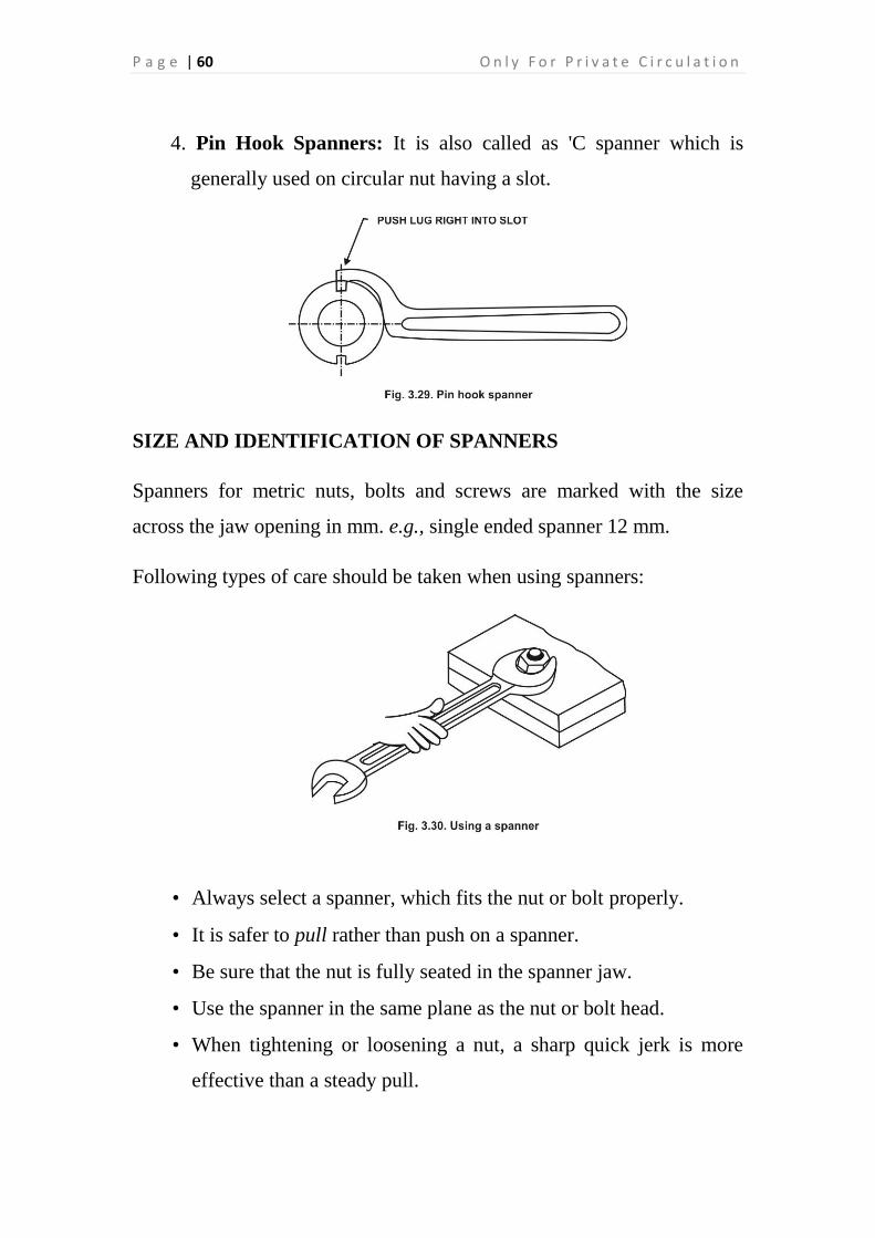
4. Pin Hook Spanners: It is also called as 'C spanner which is
generally used on circular nut having a slot.
SIZE AND IDENTIFICATION OF SPANNERS
Spanners for metric nuts, bolts and screws are marked with the size
across the jaw opening in mm. e.g., single ended spanner 12 mm.
Following types of care should be taken when using spanners:
• Always select a spanner, which fits the nut or bolt properly.
• It is safer to pull rather than push on a spanner.
• Be sure that the nut is fully seated in the spanner jaw.
• Use the spanner in the same plane as the nut or bolt head.
• When tightening or loosening a nut, a sharp quick jerk is more
effective than a steady pull.

S k i l l s T r a i n i n g f o r E n g i n e e r i n g & P r o d u c t i o n S y s t e m s P a g e | 61
DEFECTS IN SPANNERS
Spanners have their jaws slightly wider than the width of the nut to place
them into the position easily. While using place the spanner so that its
jaws bear fully on the flats of the nut. The incorrect use damages the
spanners. Defective spanners are dangerous for use; therefore the use of
defective spanners should be avoided. Generally following defects are
found in spanners: 1. In the open ended spanners, following defects a
found
(a) Crack
(b) Jaws sprung
(c) Jaws worn out and rounded
2. In the ring spanners, following defects are found Crack
(a) Worn out and rounded internal serrations.
3. In the socket spanner following defect is found
(a) Worn out and rounded internal serrations.
4. In the tubular box spanners following defects are found Split
corner

P a g e | 62 O n l y F o r P r i v a t e C i r c u l a t i o n
(a) Hexagon worn out and rounded.
PLIERS
Introduction: A pliers is a hand tool having two legs joined by pivot. Its
each leg consists of a long handle and a short jaw. It is classified by the
shape of mouth and overall length. The overall length varies from 150
mm to 230 mm. It is generally made of cast steel.
Parts: The parts of combination pliers are shown in Fig. 3.32.
• Its flat grip is used for general gripping.
• Its pipe grip is used for gripping cylindrical jobs.
• Its joint cutters are used for cutting or shearing off steel wires.
• Its side cutters are used for cutting off soft wires.
• Its handle is used for applying pressure by hand.

S k i l l s T r a i n i n g f o r E n g i n e e r i n g & P r o d u c t i o n S y s t e m s P a g e | 63
Types: Generally following pliers are used:
1. Side Cutting Pliers: It has two jaws with cutting edges to cut soft
wires. It is generally used in workshop. See Fig. 3.33.
2. Flat Nose Pliers: It consists of tapered wedge jaws with flat gripping
surfaces (either smooth or serrated). It is used for bending and folding
narrow strips of thin sheet metal. See Fig. 3.34.
3. Round Nose Pliers: It consists of tapered round shaped jaws which
is generally used to shape loops in wires and to form curves in light
metal strips. This type of plier is generally used by electricians and
radio mechanics. See Fig. 3.35.

P a g e | 64 O n l y F o r P r i v a t e C i r c u l a t i o n
4. Slip-joint Pliers: These pliers are available in various ranges of jaw
openings. It is generally used for gripping purpose. See Fig. 3.36.
Hand tools demonstration & practice on utilization of hand tools
DAY 10: 12.30 PM- 04.30 PM

S k i l l s T r a i n i n g f o r E n g i n e e r i n g & P r o d u c t i o n S y s t e m s P a g e | 65
Revision Of Last Day’s Lecture
Cutting tools & operations
A file is a hardened steel tool having parallel rows of cutting edges on its
surface. The main parts of a file are tang, heel, face, edge and point,
Files are classified and named according to three main factors : size, type
or cut of teeth, and sectional form. The size of a file is indicated by its
length, which is the distance from the point to the heel, without the tang.
The files for fine work vary from 100 to 200 mm and those for heavier
work vary from 200 to 450 mm in length.
DAY 11: 10:15 AM - 12.00 PM
DAY 11: 10:00 AM- 10:15 AM

P a g e | 66 O n l y F o r P r i v a t e C i r c u l a t i o n
TYPES OF CUTS
There are four types of cuts: Single cut, Double cut, Rasp cut and Curved
cut file.
The selection of a file with a particular type of cut is based on the
material to be filed. Single cut files are used for filing soft materials.
GRADES
Grades are determined by the spacing of the teeth.
• Rough file is used for removing rapidly a larger quantity of metal.
• Bastard file is used in cases where there is a heavy reduction of
material.
• Second cut file is used to give a good finish on metals.
• Smooth file is used to remove small quantity of material and to

S k i l l s T r a i n i n g f o r E n g i n e e r i n g & P r o d u c t i o n S y s t e m s P a g e | 67
give a good finish.
• Dead smooth file is used to bring to accurate size with a high
degree of finish.
File Shapes. The shape of a file is specified by its cross-section.
Flat file has rectangular cross-section. The edges along the width
are parallel up to two-thirds of the length, and then they taper
towards the point. The faces are double cut, and the edges single
cut. It is used for general-purpose work.

P a g e | 68 O n l y F o r P r i v a t e C i r c u l a t i o n
Square file has square cross-section and is also parallel for about
two-thirds of its length after which it tapers off. It has double-cut
teeth on all its faces. It is used for filing corners and slots.
Hand file is similar to flat file except that it has constant width
throughout its length and tapers off only in thickness. Both the
faces are double cut, one edge single cut and the other edge uncut.
The uncut edge is called safe edge. Because of the safe edge, it is
useful for filing surfaces, which are at right angles to surfaces
already finished.
Pillar file is similar to flat file except that it is narrower. It is used
for filling keyways, fillets and narrow slots.

S k i l l s T r a i n i n g f o r E n g i n e e r i n g & P r o d u c t i o n S y s t e m s P a g e | 69
Round file has a circular cross-section and is parallel for about
two-thirds of its length. It is used for producing rounded corners,
round slots, and for opening out holes.
Half round file has one half round and other half flat. It is used for
jobs involving the formation of a radius.
Triangular (or three square) file has its edges at an angle of 60°
each and is used for comers with angles less than 90°. It is double
cut on all faces.

P a g e | 70 O n l y F o r P r i v a t e C i r c u l a t i o n
Knife file is knife shaped and the included angle of its sharp edge
is generally 10°. It is used for finishing sharp corners of slots and
grooves.
Warding file is of rectangular section, and is similar to flat file
except that it is thinner and parallel along its thickness. It is useful
for cutting narrow slots.
Mill saw file is similar to flat file except that it is parallel along
both its width and thickness.
Swiss pattern files are similar to ordinary files except that they are
made to much more exact measurements.
Needle files belong to swiss pattern file family. They are used by
tool makers, die makers and watch makers.

S k i l l s T r a i n i n g f o r E n g i n e e r i n g & P r o d u c t i o n S y s t e m s P a g e | 71
FIILING
While filing a work piece, it should be held a little below the height of
the elbow. It should be held tightly in a vice. The part to be filed should
be near to the vice jaws to keep the work from chattering.
Grasp the handle of the file with the right hand and hold the palm against
the end with the thumb on top. For heavy filing, place the palm of the left
hand on the point of the file with the fingers pressing against the
underside. For light filing, the thumb of the left hand should be placed on
the top of the file. Draw filing is done by holding the file as shown in Fig.
7.12. When the file becomes clogged with chips, it should be cleaned
with a file card.

P a g e | 72 O n l y F o r P r i v a t e C i r c u l a t i o n
FILING TECHNIQUES
1. Straight Filing: This filing is done by pushing the file as straight as
possible. It gives good appearance on the surface because the file
marks are in one direction.
2. Cross Filing: In this filing, filing strokes are made initially at an
angular direction to the edge of the workpiece and then direction of
filing is changed.
3. Draw Filing: In this filing the direction of filing stroke is
perpendicular to the axis of the file. This filing is done by grasping
the both ends with hands for pushing and pulling over the

S k i l l s T r a i n i n g f o r E n g i n e e r i n g & P r o d u c t i o n S y s t e m s P a g e | 73
workpiece.
4. Curve Filing: This filing is done on round jobs and the file is
moved in circular action.
5. Rounding a Corner: The file should be used in the manner shown in
Fig. 7.13. This method ensures that the teeth of the file cut all of the
time. The majority of the metal should be removed from the corner
before using this technique.
6. Enlarging a Hole: The file should move about a quarter of the circle
with each stroke of the file. This prevents the file forming a groove at
one point
P a g e | 74 O n l y F o r P r i v a t e C i r c u l a t i o n
7. Filing into a Corner: Each edge of the corner should be treated
separately, so that the other edge will not be damaged. A safe edge
file (hand file) is used; the safe edge is used against the corner.
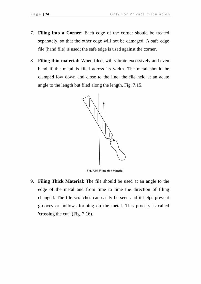
8. Filing thin material: When filed, will vibrate excessively and even
bend if the metal is filed across its width. The metal should be
clamped low down and close to the line, the file held at an acute
angle to the length but filed along the length. Fig. 7.15.
9. Filing Thick Material: The file should be used at an angle to the
edge of the metal and from time to time the direction of filing
changed. The file scratches can easily be seen and it helps prevent
grooves or hollows forming on the metal. This process is called
'crossing the cut'. (Fig. 7.16).

S k i l l s T r a i n i n g f o r E n g i n e e r i n g & P r o d u c t i o n S y s t e m s P a g e | 75
If it is necessary to file part of a job a great distance from an edge, the
handle will not allow the file to lie flat on the metal. To overcome this,
bend the tang of the file to an angle which lifts the handle off the metal.
The file can then be used
10. Filing Soft Materials: Special files are manufactured for filing soft
metals. These files have specially shaped teeth so they will cut the
metal without clogging the teeth too often. If these files are not
available, an old file with worn teeth should be used so that if it
becomes clogged and cannot be cleaned it may be discarded or left
for this use only.
11. Removing scale: The scale on steel or cast iron is much harder than
the metal itself. If it is filed in the normal manner it will blunt the
teeth on the file very quickly and hence render the file useless. The
scale on steel is removed with the toe or edge of the file before filing

P a g e | 76 O n l y F o r P r i v a t e C i r c u l a t i o n
is attempted. With cast iron the scale is either chipped or ground
away first.
Some Other Hints
1. Convexity of File: The file has a slight convexity in lengthwise
instead of straight for the following reasons:
(a) For reducing the friction with the work piece and easy filing.
(b) For giving a better distribution of the pressure and making up slight,
but inevitable difference of the filing movement.
(c) For filing with less pressure.
(d) Filing of flat surface is made easier. (Fig. 7.18)
2. Taper of File: In some files both the edges are parallel to each other
which are known as blunt files. But most of the files are tapered for

S k i l l s T r a i n i n g f o r E n g i n e e r i n g & P r o d u c t i o n S y s t e m s P a g e | 77
one-third of the length towards the point which can be used for filing
the slots having less width than the width of file.
3. Pinning of File: While filing, clogging of teeth by chips is known as
pinning of file and due to this, scratches are formed on the workpiece
being filed. The following are the main reasons for pinning of file:
(a) When filing soft materials.
(b) When using a smooth file with greater pressure. The pinning of
file can be avoided by cleaning a file with a file card or brush
and file cleaner whenever necessary.
4. Pitch of File: The distance between the corresponding points on
adjacent teeth is called the pitch of file.
5. Grade of Cut: It indicates the fineness and coarseness of cut on file
i.e., number of cuts per 1 cm length on the file.
6. Stroke of File: The file is pushed forward over the workpiece in the
cutting stroke and is pulled backward in return or non-cutting stroke.
These two actions are known as one stroke of file. The average speed
for filing should be 40 to 60 strokes per minute.

P a g e | 78 O n l y F o r P r i v a t e C i r c u l a t i o n
FILE HANDLE
File handles are generally made of wood or from paper laminates.
The length of the handle should be suitable to the size of file. The
hole diameter in the handle should not be larger than the cross
sectional size measured in the middle of the file tang. This hole is
made either by drilling or by burning out. A ferrule is fixed on the
handle to avoid breakage of handle when fixing a file in it.
Marking & filing on MS Flat by various techniques & types of files
DAY 11: 12.30 PM- 04.30 PM

S k i l l s T r a i n i n g f o r E n g i n e e r i n g & P r o d u c t i o n S y s t e m s P a g e | 79
Revision Of Last Day’s Lecture
Cutting tools & operations
HACKSAW
The hacksaw is a hand tool used to cut metal. Its four main parts are :
frame, blade, handle and adjusting wing nut. The frames on most
hacksaws may be flat or tubular. Some hacksaws have adjustable
frames to accommodate various hacksaw blade lengths. There are two
different types of hacksaw handles: straight handle and pistol grip
handle. The pistol grip handle has the advantages:
• The operator can give the required sawing effort in a
direct line with the blade.
• There is less risk of twisting the blade when sawing.
DAY 12: 10:15 AM - 12.00
PM
DAY 12: 10:00 AM- 10:15
AM

P a g e | 80 O n l y F o r P r i v a t e C i r c u l a t i o n
Hacksaw blades are made of high grades of steel such as tool steel, high-
speed steel, or tungsten-alloy steel. The saw blades generally used are 'A'
in. (12.7 mm) wide, in standard lengths of 250 mm and 300 mm. There is
a hole at each end of the blade for mounting it on the hacksaw frame.
Two types of hacksaw blades are available - all hard blades and flexible
blades. All hard blades are hardened full length between the pin and the
holes. In flexible blades, only the teeth are hardened. Because of their
flexibility, these blades are useful-for cutting along curved lines.
The distance between adjacent teeth is called the pitch. The various types
of pitches in use are: coarse (1.8 mm); medium (1.4 mm and 1.0 mm);
and fine (0.8 mm). It is important to use the right pitch for the work
being cut.
Select a blade as coarse as possible in order to provide plenty of chip
clearance and cut through the work quickly. The blade selected should
have at least two teeth in contact with the work so that the work cannot
jam between the teeth and strip the teeth from saw blade. To prevent the
saw blade binding when penetrating into the material, the cut is to be
broader than the thickness of the saw blade. This is achieved by the
setting of the saw teeth. There are two types of saw settings :
• Staggered Set. Alternate teeth or groups of teeth are staggered.
• Wave Set. The teeth of the blade are arranged in a wave form.
Specification: Hacksaw blades are specified by the length, pitch and type
i.e., hacksaw blade 300 x 1.8 mm, low alloy all-hard.
Selection of Blade: The blade should be selected according to the
strength and size of material to be cut.

S k i l l s T r a i n i n g f o r E n g i n e e r i n g & P r o d u c t i o n S y s t e m s P a g e | 81
Selection of Hacksaw Blade
S.No. Material to be cut Pitch in mm
1. Soft Materials like copper, brass,
lead etc.
1.8
2. Mild steel, cast iron 1.4
3. Medium carbon steel 1.0
4. High carbon steel, alloy steel,
sheets etc.
0.8
1. The hacksaw blade should be selected according to the hardness of
the metal to be cut. Fine pitched blades are suitable for hard metals
and coarse pitched blades are suitable for soft metals.
2. The hacksaw blade should be selected according to the thickness of
the metal to be cut. Fine pitched blades are suitable for thin section
metals and coarse pitched blades are suitable for thick section metals.

P a g e | 82 O n l y F o r P r i v a t e C i r c u l a t i o n
Hack sawing: The following points should be noted while hack sawing:
1. Check and adjust the blade tension. The blade should be fixed in the
frame teeth pointing forward i.e., towards the wing nut.
2. Secure the job in the vice. Use vice clamps if necessary.
3. Take the guiding initial cut by placing the thumb nail by the side of
the blade and see 2-3 teeth remain in contact with the job. (Fig. 7.23)
4. If hacksaw does not start readily, file a 'V' shape at the starting point.
5. After taking initial cut, saw along scribed line.
6. Start the cut with light, steady and forward stroke.
7. At the end of stroke, relieve the pressure, draw the blade straight
back. Don't use pressure on return stroke.
8. After the first few strokes, make the stroke as long as the hacksaw
will allow.
9. At the end of the cut, slow down to control the saw.
10. After finishing, clean the chips from the blade, job and work place.

S k i l l s T r a i n i n g f o r E n g i n e e r i n g & P r o d u c t i o n S y s t e m s P a g e | 83
Precautions
1. The hacksaw blade should be fixed firmly in the frame with proper
tension.
2. The job should be firmly clamped in the vice.
3. Proper grade of blade should be selected according to the material to
be cut.
4. The blade should be kept cool during cutting.
5. The pressure should be reduced on the saw when it is almost through
the cut.
6. Do not use new blade in the cut made by old blade.
Marking & Cutting using Hexa blade Hands on practice
DAY 12: 12.30 PM- 04.30
PM

P a g e | 84 O n l y F o r P r i v a t e C i r c u l a t i o n
Revision Of Last Day’s Lecture
Cutting tools & operations
CHISEL
A chisel is a hand tool made of hexagonal or octagonal bars of tool steel.
One end is shaped for the purpose of cutting and other end to receive the
impact of hammer blows. One-third of the chisel length from the cutting
edge side is heat-treated. The length of the chisel ranges from 150 to 200
mm.
Types of chisels
Flat chisel is a general-purpose chisel. The cutting edge angle is ground
depending upon the material is be chiseled. It is 120-150 mm long.
Crosscut chisel is mainly used for cutting keyways, grooves, and slots. It
is also known as cape chisel. The width of the cutting edge is 5-9 mm. It
can be used in places where the wider flat chisel cannot be used.
DAY 13: 10:15 AM - 12.00
PM
DAY 13: 10:00 AM- 10:15
AM

S k i l l s T r a i n i n g f o r E n g i n e e r i n g & P r o d u c t i o n S y s t e m s P a g e | 85
Half round chisel is used for making grooves in bearings, making fillet
radii or for roughing out small concave radii.
Diamond chisel is used for chipping sharp corners for making V-shaped
grooves.
Round nose chisel has its cutting edge given a slight curvature to make
the cutting more effective.
Web chisel: It is also called as punching chisel which is used for
separating metals after chain drilling.

P a g e | 86 O n l y F o r P r i v a t e C i r c u l a t i o n
The continuous use of a chisel deforms the shape of its head and spreads
out its ends. This is called mushrooming. The shape of the head should
always be well ground, otherwise flying pieces of metal could hit the
workman when a hammer blow is given. Mushroom ends present
difficulty in handling and could injure the hand of the workman using
the chisel.
CHIPPING OPERATION
Chipping is an operation in which a layer of metal is removed from the
surface in the form of chips. The correct point angle and angle of
inclination generate the correct rake and clearance angles. The
inclination of the chisel is not measured but it is sensed by skilled worker
and adjusted with the motion of hand.

S k i l l s T r a i n i n g f o r E n g i n e e r i n g & P r o d u c t i o n S y s t e m s P a g e | 87
If the clearance is too low or zero, the rake angle increases, then cutting
angle cannot penetrate into the job causing slippage of the chisel.
If the clearance angle is too much, the rake angle reduces. The cutting
edge digs in and the cut progressively increases. Fig. 7.33

P a g e | 88 O n l y F o r P r i v a t e C i r c u l a t i o n
GRINDING OF CHISEL
The following points should be noted while grinding a chisel:
1. If the head of the chisel has expanded due to working, it should be
ground in proper shape.
2. The blunt cutting edge of chisel should be ground to correct angle
according to material to be cut.
3. The cutting edge of flat chisel should be ground in slight convex
form.
4. The pressure on chisel against the revolving grinding wheel should
not be high.
5. Dip the chisel in water often to keep up the temper.
6. Check the cutting angle with a gauge or a protractor.
METHOD OF CHIPPING
The following points should be noted while chipping with a flat chisel:
1. Clamp the job in the vice securely. If required support the job with a
piece of hard wood.
2. Chamfer the front side of the job to give seat to the cutting edge of
chisel.
Point Angle and Angle of Inclination
Material to be cut Point Angle Angle of
Inclination
High carbon steel 65° 39.5°
Cast iron 60° 37°
Mild steel 55° 34.5°
Brass 50° 32°
Copper 45° 29.5°
Aluminum 30° 22°

S k i l l s T r a i n i n g f o r E n g i n e e r i n g & P r o d u c t i o n S y s t e m s P a g e | 89
3. Fix a chipping guard on the work bench for safety.
4. Wear safety goggles for protection of eyes.
5. Grasp the chisel in left hand on the shank 15-20 mm from the head
top.
6. Do not grip or press the chisel to the workpiece too tightly.
7. Hold the hammer in right hand and strike it on the chisel.
8. Move the chisel from right to left after each blow of hammer.
9. Do not chip more metal at a time.
10. Do not give heavy blow when cut reaches at the other end.
11. During chipping focus the eyes on the cutting edge rather than at
the head of the chisel.
Precautions
1. Use safety goggles while chipping or grinding a chisel.
2. Do not use blunt and mushroom-headed chisel.
3. The face of hammer and head of chisel should be free from oil or
grease.
4. Grasp the hammer handle at its far end.
5. Hold the job in the vice securely with proper packing of hard wood
if required.
6. Use chipping guard while chipping.

P a g e | 90 O n l y F o r P r i v a t e C i r c u l a t i o n
SCRAPER
Scraping is a method of removing the high spots from a surface to
allow parts to fit together accurately so as to reduce wear, or to provide a
flat surface for measuring purposes, such as for a surface plate. It may
also be used to decorate the metal. Various types of scrapers are:
• Flat scraper, used for scraping of flat surfaces.
• Half round scraper, used for scraping of curved surfaces such
as bearings.
• Three square scraper, used for similar purposes as the half
round scraper but usually on smaller curves.
• Bull nose scraper, used for scraping of large curved surfaces
such as large bearings.

S k i l l s T r a i n i n g f o r E n g i n e e r i n g & P r o d u c t i o n S y s t e m s P a g e | 91
Scraping Pigments: Irregularities on the surface of the workpiecs can be
detected by coloring it with pigment. The following pigments are
generally used:
(a) Prussian blue
(b) Lampblack
(c) Red Lead mixed with oil
Method of Scraping on Flat Surface
The following sequence should be noted while scraping on flat
surface:
1. Select a flat scraper of suitable size,
2. Clean the surface plate and apply thin coating of Prussian
blue.
3. Rub the finished work piece on the surface plate to take high
spots.
4. Clamp the work piece in a vice securely.
5. Stand in front of vice as easy as you can.
6. Hold the scraper in hands and set it at 25°to 30° to the work
surface.
7. Press the cutting edge of the scraper to the smeared surface and
push it forward to remove high spots.
8. Again rub the work piece on the surface plate to take other high
spots.
9. Repeat the same operation till the Prussian blue is transferred
uniformly on the whole surface.

P a g e | 92 O n l y F o r P r i v a t e C i r c u l a t i o n
10. The quality of surface can be obtained by taking more number of
bearing spot per unit area and check the surface with a control
frame 25 x 25 mm.
11. After completion of work clean scraper, work piece and surface
plate.
Sharpening a Flat Scraper
After long use the cutting edge of the scraper may become dull which
requires resharpening. The following points should be noted while
sharpening a flat scraper:
1. Start the grinding machine.
2. Hold the scraper in hands (within 25 to 30 mm of the cutting
edge) and place it on the tool rest at right angle to the periphery
of grinding wheel.
3. Rock the scraper gently in horizontal plane without A losing
contact with the grinding wheel to give slight convexity to the
cutting edge.
4. Grind the flat surface of the scraper.
5. Finish the cutting edge of the scraper on the oil stone.
6. Finish the flat surface of the scraper on the oil stone.
Hands on practice on Chipping & scrapping processes
DAY 13: 12.30 PM- 04.30 PM

S k i l l s T r a i n i n g f o r E n g i n e e r i n g & P r o d u c t i o n S y s t e m s P a g e | 93

P a g e | 94 O n l y F o r P r i v a t e C i r c u l a t i o n
THEORY ASSESSMENT II
PRACTICAL ASSESSMENT II
DAY 14: 12:30 AM - 04.30 PM
DAY 14: 10:00 AM- 12:00 AM

S k i l l s T r a i n i n g f o r E n g i n e e r i n g & P r o d u c t i o n S y s t e m s P a g e | 95
Revision Of Last Day’s Lecture
Grinding
Grinding is a finishing operation. It is meant to give necessary precision
of form and accuracy by removing the excess material. Grinding is done
on a grinding machine, which makes use of a grinding wheel rotating at a
high speed to cut the material.
Grinding Wheel : It is composed of abrasive particles, a wheel and a
bonding material known as 'binder'. There are two types of abrasives:
• Natural abrasives contain emery, sandstone, corundum and
quartz.
• Artificial or manufactured abrasives are of two kinds :
(i) Aluminum Oxide (A12O3) and Silicon Carbide (SiC)
abrasives.
DAY 15: 10:15 AM - 12.00
PM
DAY 15: 10:00 AM- 10:15
AM
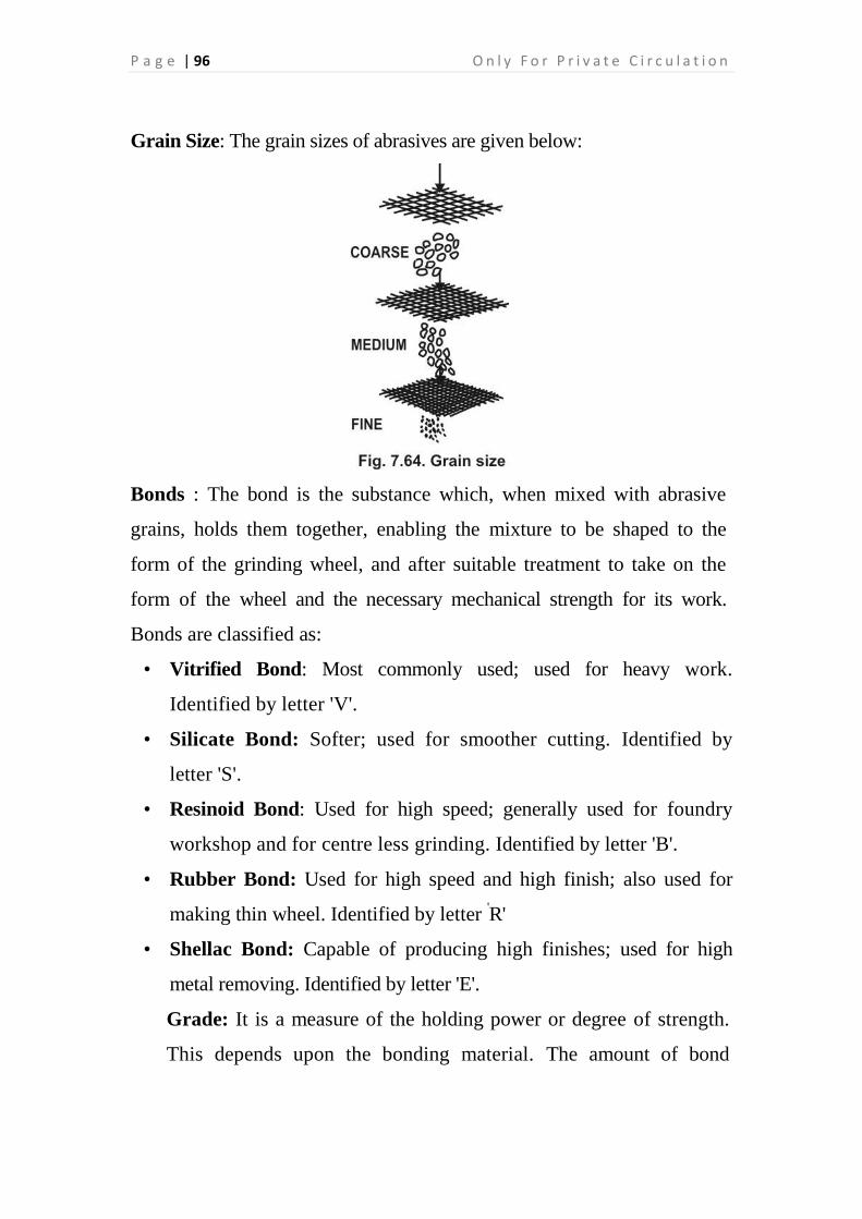
P a g e | 96 O n l y F o r P r i v a t e C i r c u l a t i o n
Grain Size: The grain sizes of abrasives are given below:
Bonds : The bond is the substance which, when mixed with abrasive
grains, holds them together, enabling the mixture to be shaped to the
form of the grinding wheel, and after suitable treatment to take on the
form of the wheel and the necessary mechanical strength for its work.
Bonds are classified as:
• Vitrified Bond: Most commonly used; used for heavy work.
Identified by letter 'V'.
• Silicate Bond: Softer; used for smoother cutting. Identified by
letter 'S'.
• Resinoid Bond: Used for high speed; generally used for foundry
workshop and for centre less grinding. Identified by letter 'B'.
• Rubber Bond: Used for high speed and high finish; also used for
making thin wheel. Identified by letter 'R'
• Shellac Bond: Capable of producing high finishes; used for high
metal removing. Identified by letter 'E'.
Grade: It is a measure of the holding power or degree of strength.
This depends upon the bonding material. The amount of bond

S k i l l s T r a i n i n g f o r E n g i n e e r i n g & P r o d u c t i o n S y s t e m s P a g e | 97
determines the wheel hardness or softness. Hardness of a grinding
wheel should not be confused with the hardness of the abrasive
grains themselves.
Grade
S.No. Group Grade
1.
2. 3.
Soft
Medium
Hard
A B C D E F G H
I J K L M N O P
Q R S T U V W X Y Z
Structure: It refers to the density of the grinding wheel or the
spacing of the abrasives. There are two types of structures: open and
dense. Wheels with open grain spacing are used on hard materials
and those with dense spacing are used for obtaining a good finish on
the work piece.
Structure
S. No. Group Structure
1.
2.
Dense
Open
12 3 4 5 6 7 8 9
10 11 12 13 14 15 16
The dense structure is suitable for grinding hard and brittle metals and for
smooth finish. The open structure is fit for grinding soft and tough metals
and for heavy stock removal. Dense and open structures are shown in below
figure

P a g e | 98 O n l y F o r P r i v a t e C i r c u l a t i o n
Shape: The grinding wheels are made in different shapes and sizes to
perform different operations and for use on different types of machines.
Generally following shapes of grinding wheels are found :
1. Straight wheel 2. Cylinder wheel
3. Tapered face wheel 4. Recessed wheel
5. Straight cup wheel 6. Flaring cup wheel
7. Dish wheel 8. Saucer wheel.
From the above mentioned grinding wheels, the straight wheel is used for
general work and other shapes are used for internal grinding, form
grinding, cutter grinding etc."

S k i l l s T r a i n i n g f o r E n g i n e e r i n g & P r o d u c t i o n S y s t e m s P a g e | 99
LOADING AND GLAZING
Loading. When grinding of soft materials such as soft steel, brass, there is
a tendency for chips to wedge in between the cutting points of the wheel.
This is called loading (Fig. 7.66)
Fig. 7.66 Loaded wheel
Glazing: Where a bond is not effective in removing the dull edges of
abrasives, the surface becomes shin in and glazed. (Fig. 7.67)
Fig. 7.67. Glazed wheel
The causes of loading and glazing are: (i) Wheels are of too dense a structure;
(ii) Too hard wheels or job; (iii) Work is too slow.
The remedies are: (i) Use soft wheel; (ii) Increase the work speed; (iii) Use
open structure.

P a g e | 100 O n l y F o r P r i v a t e C i r c u l a t i o n
Truing and Dressing: Dressing is the process of reconditioning the wheel to
make it cut better. Truing refers to shaping a wheel to a desired shape and to
make its grinding surface run true with the axis. Both truing and dressing may
be done at the same time with a mechanical wheel or an abrasive stick dresser.
Fig. 7.68. Dressing a grinding wheel
Grinding
DAY 15: 12.30 PM- 04.30 PM
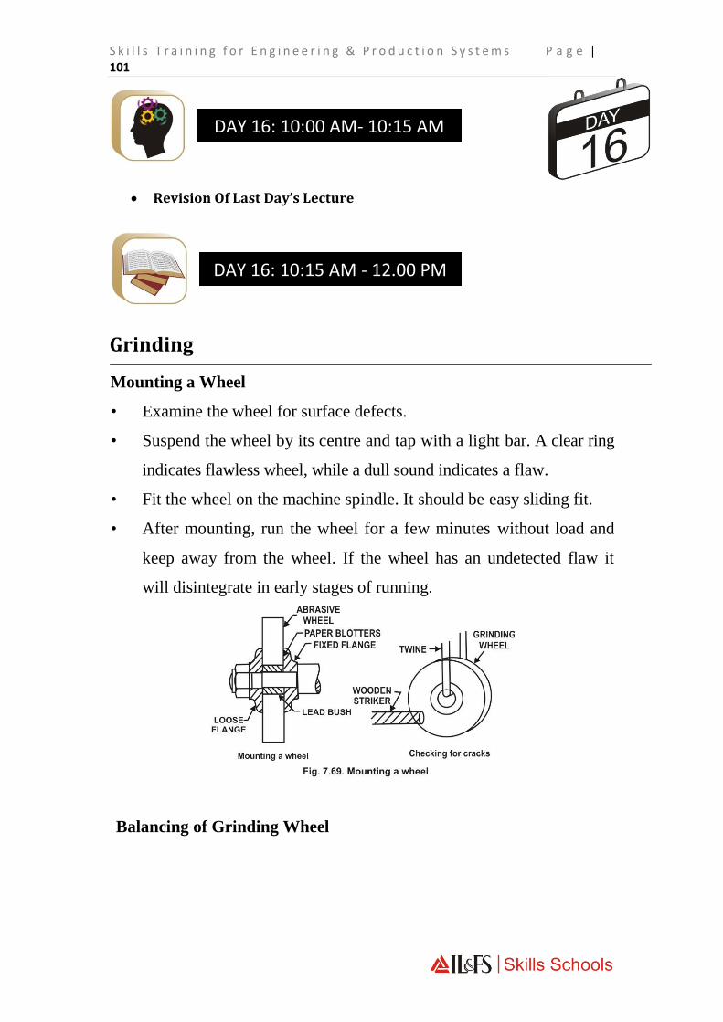
S k i l l s T r a i n i n g f o r E n g i n e e r i n g & P r o d u c t i o n S y s t e m s P a g e | 101
Revision Of Last Day’s Lecture
Grinding
Mounting a Wheel
• Examine the wheel for surface defects.
• Suspend the wheel by its centre and tap with a light bar. A clear ring
indicates flawless wheel, while a dull sound indicates a flaw.
• Fit the wheel on the machine spindle. It should be easy sliding fit.
• After mounting, run the wheel for a few minutes without load and
keep away from the wheel. If the wheel has an undetected flaw it
will disintegrate in early stages of running.
Balancing of Grinding Wheel
DAY 16: 10:15 AM - 12.00 PM
DAY 16: 10:00 AM- 10:15 AM

P a g e | 102 O n l y F o r P r i v a t e C i r c u l a t i o n
The balancing of wheel is more essential. If the wheel is out of balance, it
will produce poor work finish and will make undue strain to the machine.
The balancing of wheel is done for the following reasons :
(a)For maintaining the accuracy of the shaft and bearing.
(b)For prolonging the life of the machine.
(c) For obtaining better surface finish.
(d)For smooth running of the machine.
Small wheels may be balanced by milling a short recess on the inside of
the flange and filling it with lead. Large wheels are balanced on a
balancing stand [Fig. 7.70] and balanced by moving weights around a
recessed flange. In modern machines, a device is provided with the
grinding machines to enable balancing of wheel while it is running.
Speed of Grinding Wheel
Wheel speed is otherwise called as surface speed which is the relative
speed of the wheel and the workpiece. It is expressed in metre per
minute.
Formula:
SMPM = x D x N
1000
N=SMPM x 1000

S k i l l s T r a i n i n g f o r E n g i n e e r i n g & P r o d u c t i o n S y s t e m s P a g e | 103
xD
where SMPM = surface speed in metre per minute
N = RPM of wheel
D = diameter of wheel in mm
22 = or 3.1416
7
Example: A grinding wheel of 200 mm running at 2800 RPM. Find out the
surface speed in metre per minute.
Solution:
SMPM = x D x N
1000
= 22 x 200 x 2800
7x1000
= 1760 metre /min
GRINDING MACHINES
Generally following types of grinding machines are used :
1. Bench Grinder: It is small size grinding machine which is fitted on a
bench. One coarse and one fine wheel may be mounted in this grinder
on both ends. See Fig. 7.71 (a).

P a g e | 104 O n l y F o r P r i v a t e C i r c u l a t i o n
2. Pedestal Grinder: It is a bigger size grinder having a pedestal. Two
wheels coarse and fine are mounted on each end. It is fixed on the shop
floor directly. See Fig. 7.71(6).
3. Portable Grinder: It is a small size grinding machine having one wheel.
It can be ported where grinding work is required. See Fig. 7.71(c).
4. Flexible Shaft Grinder: This grinder has a long flexible shaft with a
grinding wheel fitted on its end which is driven by a motor fixed on a
stationary stand. It is used for rough grinding work.
5. Swing Frame Grinder: This grinder has a 2 to 3 metre long
horizontal frame with a grinding wheel which is suspended at its
centre of gravity so as to move freely. See Fig. 7.72.
6. Surface Grinder: A surface grinder is a machine which is generally
used for grinding flat surfaces. It can also be used for grinding irregular,
tapered and curved surfaces. It can produce more accurate surface to size.
7. Cylindrical Grinder: This grinder is used for grinding plain
cylindrical surfaces such as grinding of shafts, spindles, rollers etc.
8. Internal Grinder: This grinder is intended for grinding internal
surfaces. It is generally used to finish straight, tapered and formed holes to
the correct size.
9. Centreless Grinder: This grinder is generally used in production
shops. In centreless grinding the cylindrical work piece to be ground is
passed between a grinding wheel and a regulating or control wheel.

S k i l l s T r a i n i n g f o r E n g i n e e r i n g & P r o d u c t i o n S y s t e m s P a g e | 105
10. Tool and Cutter Grinder : This grinder is used for sharpening and
shaping the tools and cutters such as plain cylindrical cutter, angular
cutter, end mill, tipped tools, formed cutters etc.
Grinding
DAY 16: 12.30 PM- 04.30 PM

P a g e | 106 O n l y F o r P r i v a t e C i r c u l a t i o n
Revision Of Last Day’s Lecture
Drilling
Drilling is a cutting operation and produces round holes in metallic or
non-metallic materials. The holes are cut through by means of a cutting
tool called a drill on a drilling machine. The parts of a drill are: point,
shank, tang, body, flutes, land/margin, body clearance, web.
The different types of drills used are
DAY 17: 10:15 AM - 12.00 PM
DAY 17: 10:00 AM- 10:15 AM

S k i l l s T r a i n i n g f o r E n g i n e e r i n g & P r o d u c t i o n S y s t e m s P a g e | 107
Flat drill is the simplest form of drill, which carries a flat section
at the cutting edge. It is commonly used in brass work and for
drilling stepped holes.
Twist drill is the one most commonly used. It consists of a
cylindrical body carrying spiral flutes cut on it. It is made of high-
speed steel or high carbon steel. It has taper shank or parallel
shank. Small drills upto 12.5 mm dia. is provided with parallel
shank and larger sizes with tapered shank. Morse taper sleeve or
socket is used for holding tapered shank drills.
Centre drill is a straight shank, two fluted twist drill used when
centre holes are to be drilled on ends of a shaft.
Oil tube drill is used for deep-hole drilling. It has an oil tube
running lengthwise spirally through the body to carry oil directly
to the cutting edge.
Taper shank core drill has 3 or 4 flutes. It is used for enlarging
cored, punched or drilled holes.

P a g e | 108 O n l y F o r P r i v a t e C i r c u l a t i o n
Types of Shank : Generally following shanks are found on drills :
1. Straight Shank: It is generally found on small size drills. It can be
held in the spindle by means of a drill chuck.
2. Taper Shank: It is generally found on large size drills. It is placed
into the spindle taper bore directly or through taper sleeve or socket
and held there by friction. MT-Numbers for different sizes of drills
are shown in Table.
Morse Taper Number on Taper Shank Drill
S. No. Size of drill in mm M.T. No.
1. 3.00 to 14.00 1
2. 14.25 to 23.00 2
3. 23.50 to 31.50 3
4. 32.00 to 49.50 4
5. 50.00 to 76.50 5
6. 77.00 to 100.00 6
3. Square Taper Shank: This type of shank is square and tapered
towards the top. The drills of this shank are used on ratchet brace
drilling machine.
Size of Drill: According to the size following drills are found:
1. Fraction Drills: These drills are found in inches which are
available from 1/64" raising by 1/64", 1/32" and 1/16" in various
sizes.
2. Metric Drills: These drills are found from 1.00 mm raising by 0.1,
0.5 and 1.0 mm in various sizes.
3. Number Drills: These drills are found from 1 to 80 numbers. The

S k i l l s T r a i n i n g f o r E n g i n e e r i n g & P r o d u c t i o n S y s t e m s P a g e | 109
size of No. 1 drill is 0.228" and the size of No. 80 drill is 0.0135"
(Table on page 58).
4. Letter Drills: These drills are found from 'A' to 'Z' sizes. The size
of 'A' drill is 0.234" and the size of 'Z' drill is 0.413". (Table on page
58).
4. Indian Standard Drills: These drills are found in metric sizes
which are manufactured according to Indian Standard (BIS). The
straight shank twist drills are found from 0.2 mm to 40 mm and the
taper shank drills are found from 3 mm to 100 mm.
Drill Specification : In the Indian Standard system, the twist drills are
specified by the series to which the drills belong, the diameter, the IS
number and material with which the drill is made. The drills are made in
three types ; N (Normal); H (Hard); S (Soft). These designations
represent material to be drilled by it and the design requirement. In the
designation of the drill if the material to be cut and the point angle are not
given it should be presumed the type is 'N' and the point angle is 118°.
Drilling Machine: There are various types of drilling machines, the most
commonly used being as follows:
• Sensitive Drilling Machine: It is of two types: bench and floor. It is
lightly built. It is designed to drill small holes (approx. upto 12 mm dia.).
It is belt driven at high speed while working with small drills. It has
manual feed mechanism.
Upright Drilling Machine: It is also fixed on a bench or pillar but
normally fixed on the floor with a long pillar. It is heavily structured
because large holes are drilled on this machine.
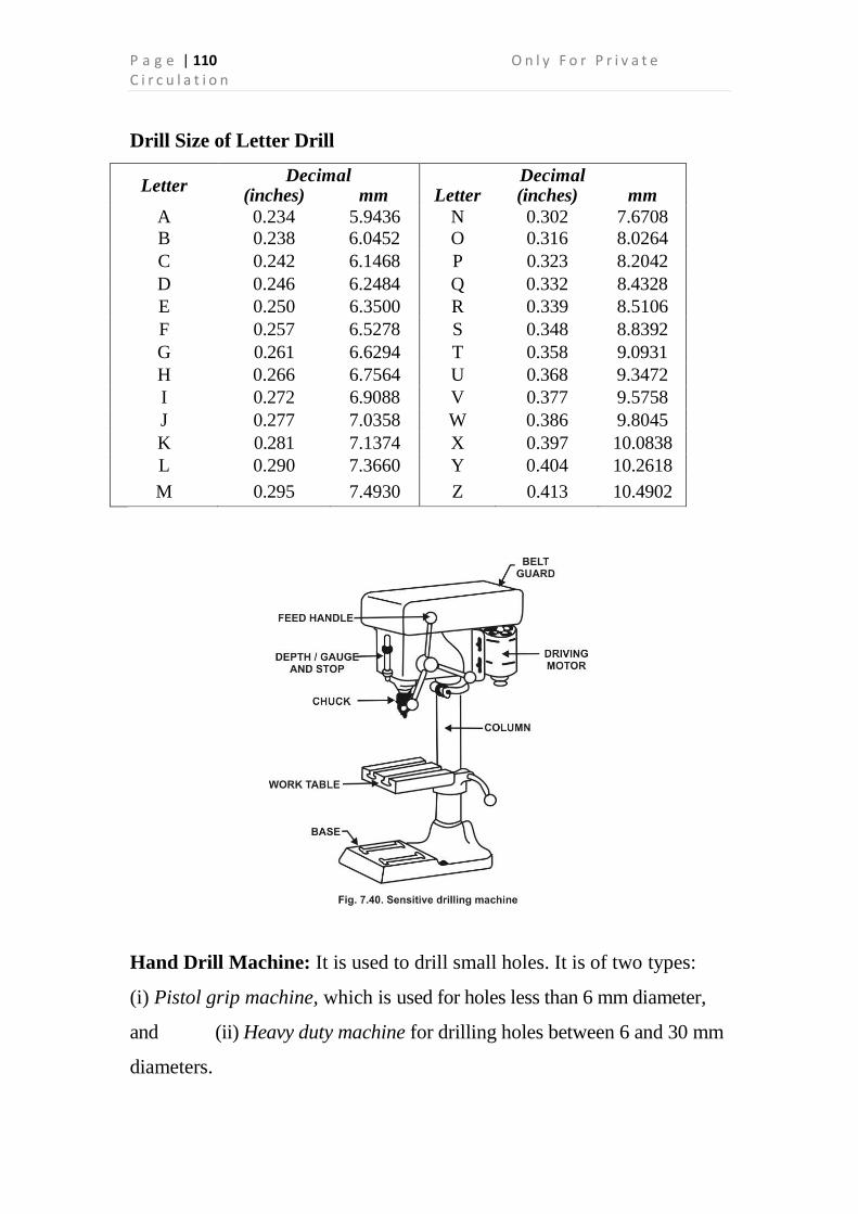
P a g e | 110 O n l y F o r P r i v a t e C i r c u l a t i o n
Drill Size of Letter Drill
Letter Decimal Decimal
(inches) mm Letter (inches) mm
A 0.234 5.9436 N 0.302 7.6708
B 0.238 6.0452 O 0.316 8.0264
C 0.242 6.1468 P 0.323 8.2042
D 0.246 6.2484 Q 0.332 8.4328
E 0.250 6.3500 R 0.339 8.5106
F 0.257 6.5278 S 0.348 8.8392
G 0.261 6.6294 T 0.358 9.0931
H 0.266 6.7564 U 0.368 9.3472
I 0.272 6.9088 V 0.377 9.5758
J 0.277 7.0358 W 0.386 9.8045
K 0.281 7.1374 X 0.397 10.0838
L 0.290 7.3660 Y 0.404 10.2618
M 0.295 7.4930 Z 0.413 10.4902
Hand Drill Machine: It is used to drill small holes. It is of two types:
(i) Pistol grip machine, which is used for holes less than 6 mm diameter,
and (ii) Heavy duty machine for drilling holes between 6 and 30 mm
diameters.

S k i l l s T r a i n i n g f o r E n g i n e e r i n g & P r o d u c t i o n S y s t e m s P a g e | 111
Multi-spindle Drilling Machine: It has a number of spindles and is used
where a number of holes of the same size or different sizes are to be
drilled on the same surface.
Gang Drilling Machine: A number of drill machine heads along with the
pillars are mounted on the same table or base. It is used for large scale
production work where different holes or different operations are done on
the same job.
Radial Drilling Machine: This machine is useful for work on heavy
and large components. The arm of the machine is capable of moving in
the radius of its column as a result. Some of the special features of this
machine are: (i) High capacity to drill large holes. (ii) Large clamping
surface and wide range in height between the spindle and base, (iii) Wide
range of spindle speeds, (iv) Elevation of arm is carried with the help of
a motor, (v) Amply rigid and avoids vibrations.
Operations on a Drilling
Machine Drilling: This refers to the operation of producing a
round hole in a solid material.
Counter sinking: Counter sinking opens the end of a drilled hole
so that it will accept the counter-sunk head °f a metal thread screw.
Counter boring: Counter boring enlarges the end of a drilled hole
to form a cylindrical opening to accept the head of a bolt or cap
screw.

P a g e | 112 O n l y F o r P r i v a t e C i r c u l a t i o n
Spot-facing: Spot-facing removes sufficient metal from the
surface around a drilled hole to form a true seat for a bolt head or
nut.
Reaming: The purpose of reaming is to bring a drilled or bored hole
to size and shape, to produce a good surface finish in the hole.
Tapping: This operation can be carried out in the drilling
machine provided the tap is fitted to a reverse tapping chuck.
Work Holding Devices: Some of the holding devices used while
drilling on drilling machine are :
Machine Vice: Most of the drilling work can be held in a machine
vice.
Angle plates: Used to hold small and large jobs especially odd-
shaped jobs.
C-Clamps: Used when clamping the work on the table or with an
angle plate.

S k i l l s T r a i n i n g f o r E n g i n e e r i n g & P r o d u c t i o n S y s t e m s P a g e | 113
Flat strap: It is a flat piece of steel with a hole near the clamping
(tapered) end.
T-bolt: Commonly used with flat strap.
Drill Holding Devices: Taper shank drills with sufficiently large
shank are directly fitted in the tapered hole of the spindle nose. A drill
with too small taper shank is held in a sleeve, which fits in the tapered
hole of the spindle. Drill chuck is used for holding straight shank drills.
A drill with too big taper shank is held in socket, which fits in the
tapered hole of the spindle.

P a g e | 114 O n l y F o r P r i v a t e C i r c u l a t i o n
Drill drift is a wedge like tool used to remove the taper shank drill
from the nose of machine spindle.
Drilling
DAY 17: 12.30 PM- 04.30 PM

S k i l l s T r a i n i n g f o r E n g i n e e r i n g & P r o d u c t i o n S y s t e m s P a g e | 115
Revision Of Last Day’s Lecture
Drilling (Contd.)
Grinding of Drill
Check the grinding wheel.
Put on the goggles.
Assuming the angle is correct, hold the cutting edge or lip parallel
with the face and perpendicular to the side.
Bring the drill lightly in contact with the wheel, and at the same
time draw it slowly upward with a slight rotary motion or stroke.
Repeat the operation until the cutting edge is sharp and correct lip
clearance is achieved. Keep the drill cool by dipping in the coolant.
DAY 18: 10:15 AM - 12.00 PM
DAY 18: 10:00 AM- 10:15 AM

P a g e | 116 O n l y F o r P r i v a t e C i r c u l a t i o n
Give the drill a half-turn and grind the other cutting edge in a
similar manner. Maintain the same angle on both lips.
The following points should be noted while grinding the drill point.
1. Cutting Edge: Both the lips should be equal in angle with the
axis of the drill. If the angles are ground unequal the drilled hole
will be larger than the size of the drill. See Fig. 7.47(a).
2. Lip Clearance: Both the lips should be equally relieved.
Generally it should be kept between 12° to 15°. If the lip clearance
angle is ground smaller, the drill will not cut and if this angle is
ground too much, the cutting edge will be weak.
3. Dead Centre: It should be kept at exact centre of the axis of the drill.
When a drill becomes shorter in length after long use, it causes
broader chisel edge which requires more pressure to penetrate the
job. So web thinning should be done by grinding both the faces on
the cutting edge.
Some Common Faults on Drill Grinding
Grinding Defects Effects
1. Cutting angle is unequal
on both sides of the axis
of drill
1. The hole is larger than the
size of the drill.
2. The length of both cutting 2. The hole is larger than the

S k i l l s T r a i n i n g f o r E n g i n e e r i n g & P r o d u c t i o n S y s t e m s P a g e | 117
lips is unequal. size of the drill.
3. Lip clearance angle is nil
or less.
3. The drill will not cut easily.
4. Lip Clearance angle is
more.
4. The cutting edges of the
drill will break.
5. Dead centre is wider. 5. The drill will not penetrate
the job.
Cutting Speed and Feed of Drill: Cutting speed of the drill is the speed
of the point on the circumference of the drill in metres per minute. A 10
mm drill rotating at 20 rpm would have the cutting speed of 10 x 3.14 x
200 mm/min or 6.28 m/min. The cutting speed depends upon the material to
be drilled and the material of which drill is made of. Feed of the drill is the
distance through which it penetrates into the workpiece in one revolution.
Cutting Speed Feed
Material being drilled
for HSS
Cutting Speed
(m/min)
Drill diameter (mm)
HSS
Rate of feed
(mm/rev)
Aluminium 70-100 1.0-2.5 0.04 - 0.060
Brass 35-50 2.6-4.5 0.050-0.100
Bronze (phosphor) 20-35 4.6-6.0 0.075-0.150
Cast iron (grey) 25-40 6.1-9.0 0.100-0.200
Copper 35-45 9.1-12.0 0.150-0.250
Mild Steel 20-30 12.1-15.1 0.200-0.300
Alloy steel 5-8 15.1-18.0 0.230 - 0.330
18.1-21.0 0.260-0.360
21.1-25.0 0.280-0.380

P a g e | 118 O n l y F o r P r i v a t e C i r c u l a t i o n
Example: Calculate R.P.M to drill a hole of 10 mm diameter with
cutting speed of 33 metre per minute.
Solution : R.P.M. = C.S. x 1000
x d
= 33 x 1000 x 7
10 x 22
Example : Find out cutting speed to drill a hole of 10 mm diameter, if
the R.P.M of the drill machine spindle are 1050.
Generally following drilling operations are performed:
1. Through Hole Drilling: It is an operation of producing circular
through hole by means of a drill i.e. the hole is passed through the
job.
2. Blind Hole Drilling: It is an operation of producing blind circular
hole by means of a drill i.e., the hole is not passed through the job,
blocking at any distance.
3. Pilot Hole Drilling: It is an operation of producing a small guiding
hole, before drilling a large size hole, which is about the half size of
the large drill. A pilot hole is drilled due to the following reasons :
(a) To locate the drill correctly due to its wide chisel edge.
(b) To keep the large sizes drill in centre.
(c) If the pressure required feed the large size drill is more.
Solution : C.S. = x d x R.P.M.
1000
= 22 x 10 x 1050
7 x 1000
= 33 metre / minute Ans.

S k i l l s T r a i n i n g f o r E n g i n e e r i n g & P r o d u c t i o n S y s t e m s P a g e | 119
Method of drilling
The following points should be noted while drilling a through hole:
1. Mount the work piece in the machine vice rigidly, use wooden
parallel packing if necessary.
2. Adjust the worktable to a convenient height.
3. Select the drill and drill holding device (drill chuck).
4. Mount the drill chuck in the machine spindle properly.
5. Hold the drill in the drill chuck firmly.
6. Start the machine and check that the drill is rotating in the centre
or not.
7. Stop the machine and adjust the height of the spindle to provide
the shortest travel feed of the drill to the work piece.
8. Select the proper speed.
9. Start the machine and lower the drill to the work-piece.
10. Feed the drill slowly into the work piece until the point of the drill
has penetrated the metal. 1L Check to see that the spot is
centrally located.
12. Originate the drill hole with proper feed, relieve the feed when the
drill is going to originate.
13. Use proper coolant where necessary.
14. Remove the drill and the work piece, clean the machine with brush.

P a g e | 120 O n l y F o r P r i v a t e C i r c u l a t i o n
Coolants for Drilling
S.No. Metal Coolant
1. High carbon steel Lard oil, soluble oil
2. Mild steel, wrought iron Lard oil, soluble oil
3. Cast iron Dry
4. Brass, Bronze Dry
5. Aluminium, Copper Kerosene oil
Precautions
1. The work piece should be firmly secured in the machine vice
or on the table of machine.
2. The drill should be properly held in the drill chuck.
3. Drill a pilot hole before drilling a large size hole.
4. Use proper coolant if necessary.
5. Don't drill with a greater feed.
6. Don't remove the chips with hand or cotton waste, use brush for
cleaning the chips.
7. Don't try to change the speed when machine is in running
condition.
8. Use drill drift to remove the drill or drill chuck from the spindle.
9. Place twist drill separately in small boxes/containers (Fig. 7.48).

S k i l l s T r a i n i n g f o r E n g i n e e r i n g & P r o d u c t i o n S y s t e m s P a g e | 121
Drilling
DAY 18: 12.30 PM- 04.30 PM

P a g e | 122 O n l y F o r P r i v a t e C i r c u l a t i o n
Revision Of Last Day’s Lecture
Counter Sinking
What is countersinking?
Countersinking is an operation of bevelling the end of a drilled hole. The
tool used is called a countersink.
Countersinking is carried out for the following purposes, to provide a
recess for the head of a counter sink screw, so that it is flush with the
surface after fixing
DAY 19: 10:15 AM - 12.00 PM
DAY 19: 10:00 AM- 10:15 AM

S k i l l s T r a i n i n g f o r E n g i n e e r i n g & P r o d u c t i o n S y s t e m s P a g e | 123
to debarring a hole after drilling for accommodating countersink rivet
heads to chamfer the ends of holes for thread cutting and other machining
processes.
Angles for countersinking
Countersinks are available in different angles for different uses.
75" countersink riveting
80° countersink self tapping screws
90° countersink head screws and debarring
120° chamfering ends of holes to be threaded or other machine
processes.
Countersinks
Countersinks of different types are available.
The commonly used countersinks have multiple cutting edges and are
available in taper shank and straight shank

P a g e | 124 O n l y F o r P r i v a t e C i r c u l a t i o n
For countersinking small diameter holes special countersinks with two or
one flute are available. This will reduce the vibration while cutting.
COUNTERSINKS WITH PILOT
For precision countersinking, needed for machine tool assembling and
after machining process, countersinks with pilots are used.
They are particularly useful for heavy duty work.
The pilot is provided at the end for guiding the countersink concentric to
the hole.
Countersinks with pilots are available with interchangeable and solid
pilots.
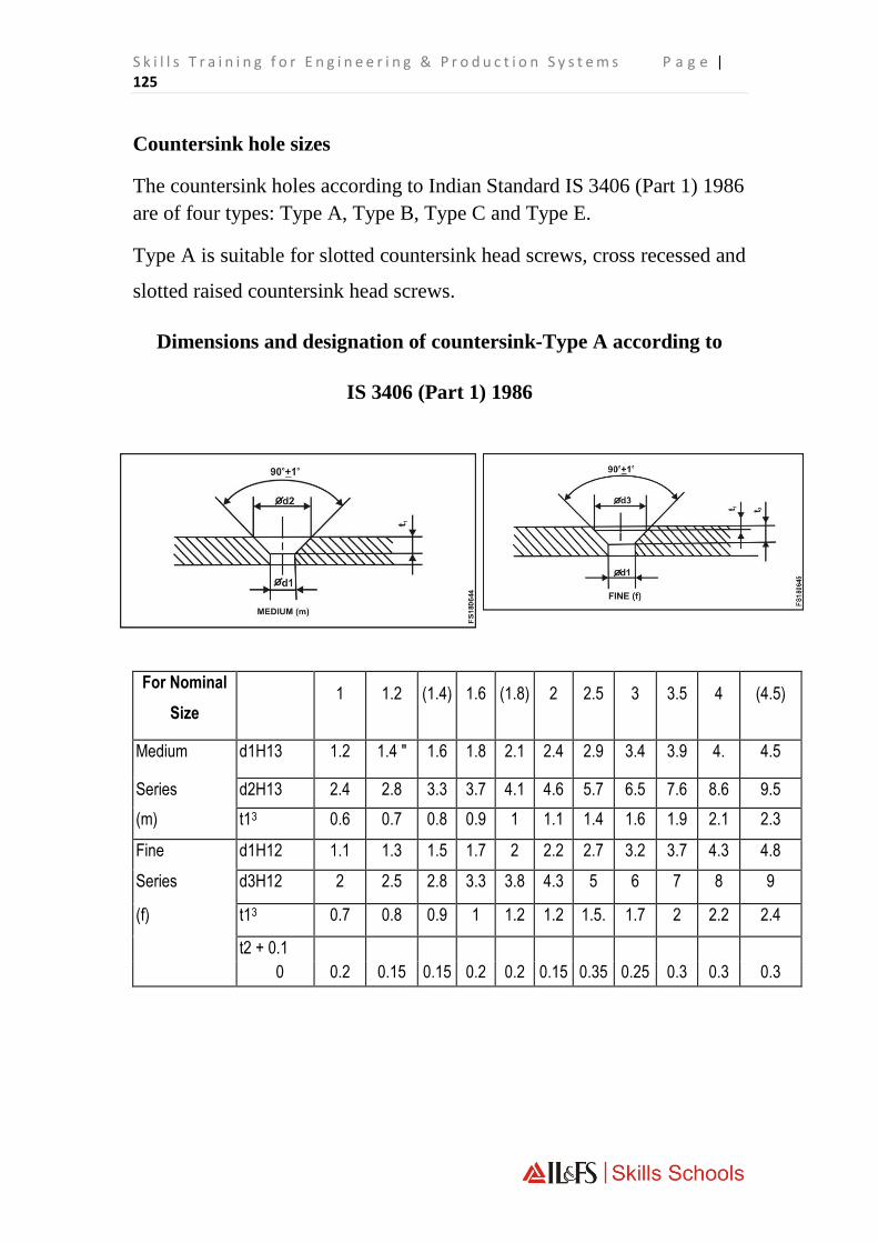
S k i l l s T r a i n i n g f o r E n g i n e e r i n g & P r o d u c t i o n S y s t e m s P a g e | 125
Countersink hole sizes
The countersink holes according to Indian Standard IS 3406 (Part 1) 1986
are of four types: Type A, Type B, Type C and Type E.
Type A is suitable for slotted countersink head screws, cross recessed and
slotted raised countersink head screws.
Dimensions and designation of countersink-Type A according to
IS 3406 (Part 1) 1986
For Nominal
Size 1 1.2 (1.4) 1.6 (1.8) 2 2.5 3 3.5 4 (4.5)
Medium d1H13 1.2 1.4 " 1.6 1.8 2.1 2.4 2.9 3.4 3.9 4. 4.5
Series d2H13 2.4 2.8 3.3 3.7 4.1 4.6 5.7 6.5 7.6 8.6 9.5
(m) t13 0.6 0.7 0.8 0.9 1 1.1 1.4 1.6 1.9 2.1 2.3
Fine d1H12 1.1 1.3 1.5 1.7 2 2.2 2.7 3.2 3.7 4.3 4.8
Series d3H12 2 2.5 2.8 3.3 3.8 4.3 5 6 7 8 9
(f) t13 0.7 0.8 0.9 1 1.2 1.2 1.5. 1.7 2 2.2 2.4
t2 + 0.1
0 0.2 0.15 0.15 0.2 0.2 0.15 0.35 0.25 0.3 0.3 0.3

P a g e | 126 O n l y F o r P r i v a t e C i r c u l a t i o n
Note 1: Size shown in brackets are of second preference.
Note 2: Clearance hole d1 according to medium and fine series of
IS : 1821 ' Dimensions for clearance holes for bolts and screws (second
revision)'
Designation: A countersink Type A with clearance hole of fine (f) series
and having nominal size 10 shall be designated as - Countersink A f 10 -
IS : 3406.
Counter Sinking
For Nominal Size 5 6 8 10 12 (14) 16 (18) 20
Medium d1H13 5.5 6.6 9 11 13.5 15.5 17.5 20 22
Series d2H13 10.4 12.4 16.4 20.4 23.9 26.9 31.9 36.4 40.4
(m) t13 2.5 2.9 3.7 4.7 5.2 5.7 7.2 8.2 9.2
Fine d1H12 5.3 6.4 8.4 10.5 13 15 17 19 21
Series d3H12 10 11.5 15 19 23 26 30 34 37
(f) t13 2.6 3 4 5 5.7 6.2 7.7 8.7 9.7
t2 + 0.1
0
0.2 0.45 0.7 0.7 0.7 0.7 1.2 1.2 1.7
DAY 19: 12.30 PM- 04.30 PM

S k i l l s T r a i n i n g f o r E n g i n e e r i n g & P r o d u c t i o n S y s t e m s P a g e | 127
Revision Of Last Day’s Lecture
Counter Boring
Counter Boring
Counter boring is an operation of enlarging a hole to a given depth, to
house heads of socket heads or cap screws with the help of a counter bore
tool
Counter bore (Tool)
The tool used for counter boring is called a counter bore. Counter bores
will have two or more cutting edges.
DAY 20: 10:15 AM - 12.00 PM
DAY 20: 10:00 AM- 10:15 AM

P a g e | 128 O n l y F o r P r i v a t e C i r c u l a t i o n
At the cutting end, a pilot is provided to guide the tool concentric to the
previously drilled hole. The pilot also helps to avoid chattering while
counter boring.
Counter bores are available with solid pilots or with interchangeable
pilots. The interchangeable pilot provides flexibility of counter boring on
different diameters of holes.

S k i l l s T r a i n i n g f o r E n g i n e e r i n g & P r o d u c t i o n S y s t e m s P a g e | 129
Spot facing
Spot facing is a machining operation for producing a flat seat for bolt
head, washer or nut at the opening of a drilled hole. The tool is called a
spot facer or a spot facing tool. Spot facing is similar to counter boring,
except that it is shallower. Tools that are used for counter boring can be
used for spot facing as well.
Spot facing is also done by fly cutters by end-cu action. The cutter blade
is inserted in the slot of the holder, which can be mounted on to the
spindle

P a g e | 130 O n l y F o r P r i v a t e C i r c u l a t i o n
Counter bore sizes and specification
Counter bore sizes are standardized for each diameter of screws as per
BIS.
There are two main types of counter bores. Type H and Type K.
The type H counter bores are used for assemblies with slotted cheese
head, slotted pan head and cross recessed
pan head screws. The type K counter bores are used in assemblies with
hexagonal socket head cap screws.
For fitting different types of washers the counter bore standards are
different in Type H and Type K.
The clearance hole d1 are of two different grades i.e. medium (m) and
fine (f) and are finished to H13 and H12 dimensions.
Representing counter bores in drawings, counter bore can be indicated
either by code designation or using the dimensions.
Using code designation

S k i l l s T r a i n i n g f o r E n g i n e e r i n g & P r o d u c t i o n S y s t e m s P a g e | 131
Using dimensions
The table given below is a portion from I S 3406 (Part 2) 1986. This gives
dimensions for Type H and Type K counter bores.
Counterbore and Clearance Hole Sizes for Different Sizes of Screws
Dimensions for H and K Type counter bores

P a g e | 132 O n l y F o r P r i v a t e C i r c u l a t i o n
For
Nominal
Size
1 1.2 1.4 1.6 1.8 2 2.5 3 (3.5) 4 5 6 8 10 12 (14) 16 18 20 22 24 27 30 33 36
d1
Medium (m)
H13
1.2 1.4 1.6 1.8 2.1 2.4 2.9 3.4 3.9 4.5 5.5 6.6 9 11 13.5 15.5 17.5 20 22 24 26 30 33 36 39
fine (f)
H 12 1.1 1.3 1.5 1.7 2 2.2 2.7 3.2 3.7 4.3 5.3 6.4 8.4 10.5 13 15 17 19 21 23 25 - - - -
H13 2.2 2.5 2.8 3.3 3.8 4.3 5 6 6.5 8 10 11 15 18 20 24 26 30 33 36 40 43 48 53 57
d2 - - - - - - - - - - - - - - 15.5 17.5 19.5 22 24 26 28 33 36 39 42
t1
Type H 0.8 0.9 1 1.2 1.5 1.6 2 2.4 2.9 3.2 4 4.7 6 7 8 9 10.5 11.5 12.5 13.5 14.5 - - - -
Type K - - 1.6 1.8 - 2.3 2.9 3.4 - 4.6 5.7 6.8 9 11 13 15 17.5 19.5 21.5 23.5 25.5 28.5 32 35 38
+0.1 +0.2 +0.4 +0.6
Tolerance 0 0 0 0
Note : Sizes given in brackets are of second preference. For details refer IS:3406 (Part 2) 1986.

S k i l l s T r a i n i n g f o r E n g i n e e r i n g & P r o d u c t i o n S y s t e m s P a g e | 133
Counter Boring
DAY 20: 12.30 PM- 04.30 PM

P a g e | 134 O n l y F o r P r i v a t e C i r c u l a t i o n
THEORY ASSESSMENT III
PRACTICAL ASSESSMENT III
DAY 21: 12:30 AM - 04.30 PM
DAY 21: 10:00 AM- 12:00 AM

S k i l l s T r a i n i n g f o r E n g i n e e r i n g & P r o d u c t i o n S y s t e m s P a g e | 135
Revision Of Last Day’s Lecture
Reamers
REAMERS
A reamer is a multipoint cutting tool used for enlarging by finishing previously
drilled holes to accurate sizes. (Fig 1)
Advantages of 'reaming'
Reaming produces high quality surface finish dimensional accuracy to close
limits.
Also small holes which cannot be finished by other processes can be finished.
Classification of reamers
Reamers are classified as hand reamers and machine reamers.
DAY 22: 10:15 AM - 12.00 PM
DAY 22: 10:00 AM- 10:15 AM

P a g e | 136 O n l y F o r P r i v a t e C i r c u l a t i o n
Reaming by using hand reamers is done manually for which great skill is
needed.
Machine reamers are fitted on spindles of machine tools and rotated for
reaming.
Machine reamers are provided with morse taper shanks for holding on machine
spindles.
Hand reamers-have straight shanks with 'square' at the end, for holding with tap
wrenches
Parts of a hand reamer
The parts of a hand reamer are listed hereunder. Refer to Fig 4.

S k i l l s T r a i n i n g f o r E n g i n e e r i n g & P r o d u c t i o n S y s t e m s P a g e | 137
Axis
The longitudinal centre line of the reamer.
Body
The portion of the reamer extending from the entering end of the reamer to the
commencement of the shank.
Recess
The portion of the body which is reduced in diameter below the cutting edges,
pilot or guide diameters.
Shank
The portion of the reamer which is held and driven. It can be parallel or taper.

P a g e | 138 O n l y F o r P r i v a t e C i r c u l a t i o n
Circular land
The cylindrically ground surface adjacent to the cutting edge on the leading
edge of the land.
Bevel lead
The bevel lead cutting portion at the entering end of the reamer cutting its way
into the hole. It is not provided with a circular land.
Taper lead
The tapered cutting portion at the entering end to facilitate cutting and finishing
of the hole. It is not provided with a circular land.
Bevel lead angle
The angle formed by the cutting edges of the bevel lead and the reamer axis.
Taper lead angle
The angle formed by the cutting edges of the taper and the reamer axis.
Terms relating to cutting geometry flutes
The grooves in the body of the reamer to provide cutting edges, to permit the
removal of chips, and to allow the cutting fluid to reach the cutting edges

S k i l l s T r a i n i n g f o r E n g i n e e r i n g & P r o d u c t i o n S y s t e m s P a g e | 139
Heel
The edge formed by the intersection of the surface left by the provision of a
secondary clearance and the flute
Cutting edge
The edge formed by the intersection of the face and the circular land or the
surface left by the provision of primary clearance
Face
The portion of the flute surface adjacent to the cutting edge on which the chip
impinges as it is cut from the work
Rake angles
The angles in a diametaral plane formed by the 'face and a radial line from the
cutting edge
Clearance angle
The angles formed by the primary or secondary clearances and the tangent to
the periphery of the reamer at the outting edge. They are called primary
clearance angle and secondary clearance angle respectively. (Fig 7)

P a g e | 140 O n l y F o r P r i v a t e C i r c u l a t i o n
Helix angle
The angle between the edge and the reamer axis.
Reamers
DAY 22: 12.30 PM- 04.30 PM

S k i l l s T r a i n i n g f o r E n g i n e e r i n g & P r o d u c t i o n S y s t e m s P a g e | 141
Revision Of Last Day’s Lecture
Reamers (Contd.)
HAND REAMERS
General features of hand reamers
Hand reamers are used to ream holes manually using tap wrenches.
These reamers have a long taper lead. This allows to start the reamer straight
and in alignment with the hole being reamed.
DAY 23: 10:15 AM - 12.00 PM
DAY 23: 10:00 AM- 10:15 AM

P a g e | 142 O n l y F o r P r i v a t e C i r c u l a t i o n
Most hand reamers are for right hand cutting.
Helical fluted hand reamers have left hand helix. The left hand helix will
produce smooth cutting action and finish.
Most reamers, machine or hand, have uneven spacing of teeth. This feature of
reamers helps to reduce chattering while reaming. (Fig 3)
Types, features and functions
Hand reamers with different features are available for meeting different reaming
conditions. The commonly used types are listed here under:
Parallel hand reamer with parallel shank
A reamer which has virtually parallel cutting edges with taper and bevel lead.
The body of the reamer is integral with a shank. The shank has the nominal
diameter of the cutting edges. One end of the shank is square shaped for tuning
it with a tap wrench. Parallel reamers are available with straight and helical
flutes. This is the commonly used hand reamer for reaming holes with parallel
sides.
Reamers commonly used in workshop produce H8 holes.

S k i l l s T r a i n i n g f o r E n g i n e e r i n g & P r o d u c t i o n S y s t e m s P a g e | 143
Hand reamer with pilot For this type of reamer, a portion of the body is
cylindrical^/ ground to form a pilot at the entering end. The pilot keeps the
reamer concentric with the hole being reamed.
Socket reamer with parallel shank
This reamer has tapered cutting edges to suit metric morse tapers. The shank is
integral with the body, and is square shaped for driving. The/flutes are either
straight or helical.
The socket reamer is used for reaming internal Morse tapered holes.
Taper pin hand reamer
This reamer has tapered cutting edges for reaming taper holes to suit taper pins.
A taper pin reamer is made with a Taper of 1 in 50. These reamers are available
with straight or helical flutes.
Use of straight and helical fluted reamers
Straight fluted reamers are useful for general reaming work. Helical fluted
reamers are particularly suitable for reaming holes with keyway grooves or

P a g e | 144 O n l y F o r P r i v a t e C i r c u l a t i o n
special lines cut into them. The helical flutes will bridge the gap and reduce
binding and chattering.
Material of hand reamers
When the reamers are made as a one-piece construction, then the reamers are
made as a one-piece construction, high speed steel is used. When they are made
as two piece constructions then the cutting portion is made of high speed steel
while the shank portion is made of carbon steel. They are butt-welded together
before manufacturing.

S k i l l s T r a i n i n g f o r E n g i n e e r i n g & P r o d u c t i o n S y s t e m s P a g e | 145
Specifications of a reamer
To specify a reamer the following data is to be given.
Type Flute
Shank end Size
Example: Hand reamer, Straight flute, Parallel shank of 20 mm.
DRILL SIZE FOR REAMING
For reaming with a hand or a machine reamer, the hole drilled should be smaller
than the reamer size.
The drilled hole should have sufficient metal for finishing with the reamer.
Excessive metal will impose a strain on the cutting edge of the reamer and
damage it.
Calculating drill size for reamer
A method generally practiced in workshop is by applying the following
formula.
Drill size = Reamed size - (Undersize + Oversize)
Finished size
Finished size is the diameter of the reamer.
Undersize
Undersize is the recommended reduction in size for different ranges of drill
diameter.

P a g e | 146 O n l y F o r P r i v a t e C i r c u l a t i o n
Under sizes for reaming
TABLE 1
Oversize
It is generally considered that a twist drill will make a hole larger than its
diameter. The oversize for calculation purposes is taken as 0.05 mm - for all
diameters of drills.
For light metals the undersize will be chosen 50% larger.
Example
A hole is to be reamed on mild steel with a 10 mm reamer.
What will be the diameter of the drill for drilling the hole before reaming?
Drill size = Reamed size - (Undersize + Oversize)
(Finished
size)
Undersize as
per
= 10 mm
table = 0.2 mm
Oversize = 0.05 mm
Drill size = 10 mm — 0.25 mm
= 9.75 mm
Diameter of
ready reamed
hole (mm)
Undersize of
rough bored
hole (mm)
under5 0.1 ............ 0.2
5 .............. 20 0.2 ............ 0.3
21 ....50 0.3 ............ 0.5
over 50 0.5 ............ 1
S k i l l s T r a i n i n g f o r E n g i n e e r i n g & P r o d u c t i o n S y s t e m s P a g e | 147
Determine the drill hole sizes for the following reamers:
i 15 mm
ii 4 mm
iii 40
mm
iv 19
mm
Answer i _______________________________________
ii _______________________________________
iii_______________________________________
iv_______________________________________
Note: If the reamed hole is under size, the cause is that the reamer is worn out.
Always inspect the condition of the reamer before commencing reaming.
FOR OBTAINING GOOD SURFACE FINISH
Use a coolant while reaming. Remove metal chips from the reamer frequently.
Advance the reamer slowly into the work.
Defects in reaming - Causes and Remedies
Reamed hole undersize
If a worn out reamer is used, it may result in the reamed hole bearing undersize.
Do not use such reamers.
Always inspect the condition of the reamer before using. Surface finish rough
The causes may be any one of the following or combinations thereof.
Incorrect application

P a g e | 148 O n l y F o r P r i v a t e C i r c u l a t i o n
Dwarf accumulated in reamer flutes Inadequate flow of coolant Feed rate too
fast.
While reaming apply a steady and slow feed-rate.
Ensure a copious supply of the coolant.
Do not turn the reamer in the reverse direction.
Reamers
DAY 23: 12.30 PM- 04.30 PM

S k i l l s T r a i n i n g f o r E n g i n e e r i n g & P r o d u c t i o n S y s t e m s P a g e | 149
Revision Of Last Day’s Lecture
Hand Tapping & Threading
Taps are cutting tools used to cut internal threads. They are made from
high quality tool steel, hardened and ground. Three are four flutes are cut
lengthwise across the threads to form cutting edges, provide clearance for the
chips, and admit cutting fluid to lubricate the tap. The end of the shank is square
so that a tap wrench can be used to turn the tap into a hole.
Hand taps are made in sets of three:
Taper tap is tapered from the end approximately eight threads and is used
to start a thread easily.
DAY 24: 10:15 AM - 12.00 PM
DAY 24: 10:00 AM- 10:15 AM
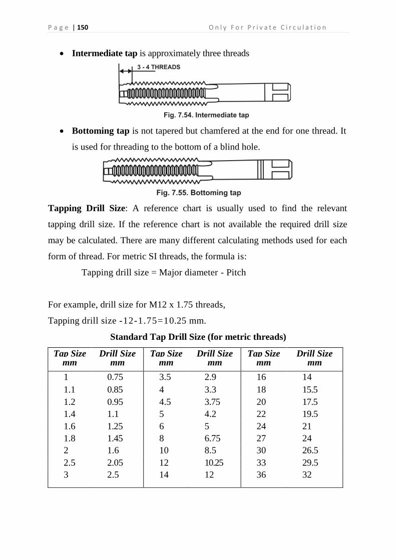
P a g e | 150 O n l y F o r P r i v a t e C i r c u l a t i o n
Intermediate tap is approximately three threads
Bottoming tap is not tapered but chamfered at the end for one thread. It
is used for threading to the bottom of a blind hole.
Tapping Drill Size: A reference chart is usually used to find the relevant
tapping drill size. If the reference chart is not available the required drill size
may be calculated. There are many different calculating methods used for each
form of thread. For metric SI threads, the formula is:
Tapping drill size = Major diameter - Pitch
For example, drill size for M12 x 1.75 threads,
Tapping drill size -12-1.75=10.25 mm.
Standard Tap Drill Size (for metric threads)
Tap Size Drill Size Tap Size Drill Size Tap Size Drill Size mm mm mm mm mm mm
1 0.75 3.5 2.9 16 14
1.1 0.85 4 3.3 18 15.5
1.2 0.95 4.5 3.75 20 17.5
1.4 1.1 5 4.2 22 19.5
1.6 1.25 6 5 24 21
1.8 1.45 8 6.75 27 24
2 1.6 10 8.5 30 26.5
2.5 2.05 12 10.25 33 29.5
3 2.5 14 12 36 32

S k i l l s T r a i n i n g f o r E n g i n e e r i n g & P r o d u c t i o n S y s t e m s P a g e | 151
For B.A. Threads
Tap Size No. Drill Size Tap Size No. Drill Size
0 No. 12 10 No. 56
1 No. 19 11 No. 58
2 No. 26 12 No. 63
3 No. 30 13 No. 65
4 No. 34 14 No. 70
5 No. 40 15 No. 72
6 No. 44 16 No. 74
7 No. 48 17 No. 76
8 No. 51 18 No. 77
9 No. 53 19 No. 79
For B.S.W. Threads
Tap Size Drill Size Tap Size Drill Size
1/8" No. 42 7/8" 47/64"
3/16" No. 29 1" 27/32"
1/4" 3/16" or No. 12 1 1/8" 61/64"
5/16" 'D'
3/8" 19/64" or 'M' 1 1/4" 1 3/64"
7/16" 'S'
1/2" 'X' or 13/32" 1 1/2" 1 19/64"
9/16" 15/32" 1 3/4" 1 1/2"
5/8" 33/64" 2" 1 47/64"
3/4" 5/8" - -
For B.S.F. Threads
Tap Size Drill Size Tap Size Drill Size
1/4" 13/64" or No. 17 3/4" 21/32"
5/16" 'F' 13/16" 23/32"
3/8" 'O' 7/8" 49/64"
7/16" 'U' 1" 7/8"
1/2" 27/64" 1 1/8" 63/64"
9/16" 31/64"
5/8" 35/64" 1 1/4" 1 7/64"
11/16" 39/64" - -
For B.S.P. Threads
Tap Size Drill Size Tap Size Drill Size
1/8" 11/32" or 'R' 1" 1 13/64"
1/4" 29/64"

P a g e | 152 O n l y F o r P r i v a t e C i r c u l a t i o n
3/8" 19/32" 1 1/8" 1 35/65"
1/2" 47/64" 1 1/4" 1 21/32"
5/8" 13/16"
3/4" 61/64" 1 3/8" 1 41/64"
7/8" 1 7/64" - -
Tap Wrench
Tap wrench is a device which is used to drive the hand taps.
Types: Generally following types of tap wrenches are used:
1. Solid Tap Wrench: It is a rigid tap wrench having one or more
square holes to suit different size of taps.
2. Adjustable Tap Wrench : It is most common tap wrench which is
found in different sizes. It is suitable for large size taps.
3. T-Handle Tap Wrench : It is small adjustable chuck having two jaws
and a handle. It is used with one hand only. This tap wrench is useful for
tapping in restricted places.

S k i l l s T r a i n i n g f o r E n g i n e e r i n g & P r o d u c t i o n S y s t e m s P a g e | 153
The following sequence should be noted while tapping through hole:
1. Check up the size of tapping hole and clamp the work piece securely in
a vice by setting the hole vertically.
2. Select the proper set of tap and tap wrench. Insert the first tap into the hole
vertically. Press the tap wrench gently with one hand against the tap and
give it a few clockwise turns to cut one or two threads and take a stable
position.
4. Use try square to check it for squareness to the work surface.
5. The inclined position should be rectified before the formation of the
threads.
6. Grip the tap wrench with both hands and turn it clockwise for making
threads. Regularly turn the tap a quarter of a revolution back to break off the
metal cuttings.
7. Use the whole set of taps, I, II & III.
8. Repeat the same procedure and use proper lubricant while tapping.
9. Use thread plug gauge to check the threads.
10. After completion of work, clean the tap and work piece
Lubricants For Tapping
S.No. Metal Lubricants
1.
2.
3.
4.
Steel
Aluminium
Cast Iron
Brass
Lard oil
Paraffin or Kerosene oil
Dry
Dry
Causes for Breakage of Tap
1. The tapping hole is smaller than the required size.
2. The tapping hole is inclined or tapered.
3. Unequal pressure is exerted on the tap wrench.
4. Tap is blunt or damaged.
5. Tap is not put vertically.

P a g e | 154 O n l y F o r P r i v a t e C i r c u l a t i o n
6. Jerk is given while rotating the tap.
7. Tap is rotated when it touches the bottom of the blind hole.
8. Failed to remove cutting chips when tapping a blind hole.
9. Failed to use taps in order.
10. Failed to turn the tap a quarter of a revolution back to break off the chips.
11. Failed to use lubricant while tapping.
Methods of Removing Broken Tap
A broken tap can be removed by using following methods :
1. By using round nose pliers if the tap is broken above the surface of
work piece.
2. By using a pin punch and hammer if a small tap is broken very near
to the surface of work piece.
3. By annealing the tap, drilling a hole in it and using a stud extractor if
the tap is broken below the surface of the work piece.
4. By treating the hole with acid.
5. By using ultra-violet ray cutting.
Stud Extractor: It is also known as Easy-out which a hand tool is having left
hand spiral. It is found in set of 5 pieces. The recommended drill size is
punched on each piece of the stud extractor. After drilling the recommended drill,
it is set on it and turned anticlockwise by a tap wrench to unscrew the broken
tap or stud.
Precautions
1. Before tapping clean the job and the tap.
2. Tapping hole should be of correct size.
3. The job should be clamped firmly in a bench vice.
4. The proper size of tap wrench should be selected.
5. Regularly turn the tap a half of a revolution clockwise and quarter of
a revolution anticlockwise.
6. If the tap refuses to enter into the hole smoothly, unscrew the tap

S k i l l s T r a i n i n g f o r E n g i n e e r i n g & P r o d u c t i o n S y s t e m s P a g e | 155
and find out what is wrong.
7. Use proper lubricant while tapping.
THREADING DIES
Threading dies are used to cut external threads on round work. The most
common threading dies are the adjustable and solid types. The round adjustable
die is split on one side and can be adjusted to cut slightly over or undersized
threads. The solid die cannot be adjusted and is generally used for re-cutting
damaged or oversized threads.
DIE STOCK
Generally following die stocks are used :
2. Solid Die Stock: It is made from a solid piece of metal having
circular body with two handles fitted on both sides of the body. Two
side screws and one centre screw are provided on the body for
holding and adjusting the die. It is also known as button pattern die
stock. This die stock is used for holding circular solid and split dies.

P a g e | 156 O n l y F o r P r i v a t e C i r c u l a t i o n
3. Adjustable Die Stock: It has a rectangular body with two handles
fitted on both sides of the body. A clamping screw is provided on the
body for adjustment of the die. It is used for holding two piece die.
3. Quick Die Stock: It has a circular body with two handles fitted on
both sides of the body. It is used for holding adjustable screw plate die.
Blank Size for Threading with Die
The diameter of the rod to be threaded should be undersize i.e., slightly smaller
than the major diameter of the thread. This blank diameter should be less by 1/10

S k i l l s T r a i n i n g f o r E n g i n e e r i n g & P r o d u c t i o n S y s t e m s P a g e | 157
or 0.1 of the pitch of thread. The following formula can be used to calculate the
blank diameter of the rod:
D = d-p x 0 . l
where D = diameter of the blank
d = diameter of the rod
p = pitch of the thread.
Example: Find out the diameter of the blank for M10 thread with 1.5 mm
pitch.
Solution: D = d-p x 0.1
= 10 - 0.15 = 9.85 mm
Method of Threading With Die
The following sequence should be noted while external threading with a circular
split die:
1. Check the diameter of the rod. The blank diameter should be less by 0.1
mm of the pitch of the thread.
2. Choose correct size of die and die stock.
3. Mark the length of the threaded portion.
4. Chamfer the starting point of the rod with a file for easy start of the
thread.
5. Clamp the rod vertically and rigidly in a vice. The end of the portion to be
threaded should be 20 to 25 mm above the top of the vice jaws.
6. Use proper lubricant at the chamfered end of the rod.
7. Clamp the circular split die in the die stock.
8. Place the die over the rod end and press with hand and give a few
clockwise turns.
9. Then grip the die stock with both hands and turn it clockwise and regularly
turn the die half a revolution anticlockwise after every one or two
revolutions to break off the chips.
10. Loosen the centre screw of the die stock and close the die slightly with side

P a g e | 158 O n l y F o r P r i v a t e C i r c u l a t i o n
screws and recut the threads.
11. Remove sharp edges and burrs.
12. Check the threads with a nut or thread ring gauge.
Lubricants for Threading with Die
S.No. Metal Lubricants
1.
2.
3.
4.
Steel
Aluminium
Cast Iron
Brass
Lard oil
Paraffin or Kerosene oil
Dry
Dry
Precautions
1. Clean the die and job before starting of thread cutting.
2. The size of the blank must be checked.
3. The starting point of the rod should be chamfered.
4. The rod should be clamped in a vice firmly.
5. The die should be turned half a revolution anticlockwise after
every one or two revolutions to break off-the chips.
6. Proper lubricants should be used while external threading with die.
7. Split or two piece die should be adjusted 2 or 3 times to finish the threads
in full depth.
8. After completion of work remove sharp edges and burrs.
Tapping
DAY 24: 12.30 PM- 04.30 PM

S k i l l s T r a i n i n g f o r E n g i n e e r i n g & P r o d u c t i o n S y s t e m s P a g e | 159

P a g e | 160 O n l y F o r P r i v a t e C i r c u l a t i o n
Revision Of Last Day’s Lecture
Hand Tapping & Threading (Contd.)
Tapping
DAY 25: 12.30 PM- 04.30 PM
DAY 25: 10:15 AM - 12.00 PM
DAY 25: 10:00 AM- 10:15 AM

S k i l l s T r a i n i n g f o r E n g i n e e r i n g & P r o d u c t i o n S y s t e m s P a g e | 161
Revision Of Last Day’s Lecture
Limits & Fits
Upper deviation
It is the algebraic difference between the maximum limit of size and its
corresponding basic size. (Fig 2) (Table 1).
Lower deviation
It is the algebraic difference between the minimum limit of size and its
corresponding basic size
Upper deviation is the deviation which gives the maximum limit of size.
Lower deviation is the deviation which gives the minimum limit of size.
Actual deviation
It is the algebraic difference between the actual size and its corresponding basic
size
Tolerance
It is the difference between the maximum limit of size and the minimum limit of
size. It is always positive and is expressed only as a number without a sign
Zero line
DAY 26: 10:15 AM - 12.00 PM
DAY 26: 10:00 AM- 10:15 AM

P a g e | 162 O n l y F o r P r i v a t e C i r c u l a t i o n
I n graphical representation of the above terms, the zero line represents the basic
size. This line is also called as the line of zero deviation. (Figs 1 and 2)
Fundamental deviation
There are 25 fundamental deviations in the BIS system represented by letter
symbols (capital letters for holes and small letters for shafts), i.e for holes -
ABCD....Z excluding I.L.O.Q&W
In addition to the above, four sets of letters JS, ZA, ZB & ZC are included. For
fine mechanisms CD, EF and FG are added
For shafts, the same 25 letter symbols but in small letters are used

S k i l l s T r a i n i n g f o r E n g i n e e r i n g & P r o d u c t i o n S y s t e m s P a g e | 163
The position of tolerance zone with respect to the zero line is shown Figs 6 and
7.

P a g e | 164 O n l y F o r P r i v a t e C i r c u l a t i o n
The Fundamental tolerance
This is also called as 'grade of tolerance'. In the Indian Standard System, there
are 18 grades of tolerances represented by number symbols, both for hole and
shaft, denoted as IT01, IT0, IT1....to IT16. A high number gives a large
tolerance zone.
The grade of tolerance refers to the accuracy of manufacture.
In a standard chart, the upper and lower deviations for each combination of
fundamental deviation and fundamental tolerance are indicated for sizes ranging
up to 500 mm. (Refer to IS 919)
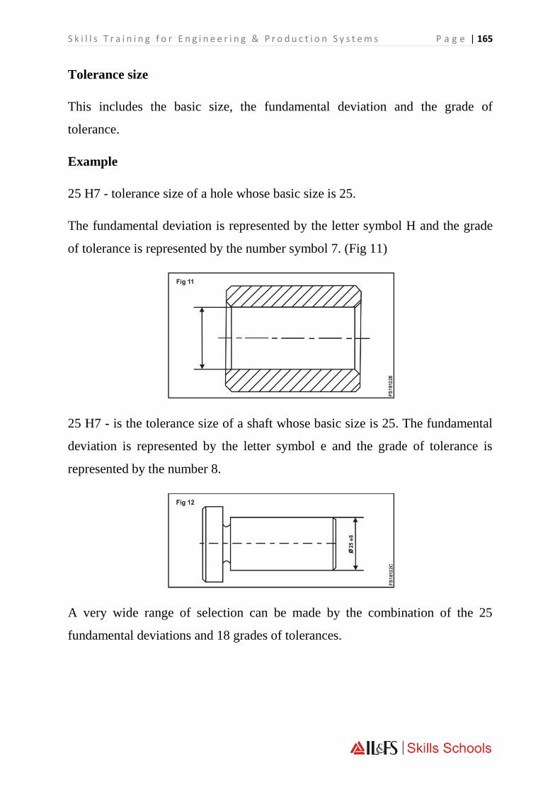
S k i l l s T r a i n i n g f o r E n g i n e e r i n g & P r o d u c t i o n S y s t e m s P a g e | 165
Tolerance size
This includes the basic size, the fundamental deviation and the grade of
tolerance.
Example
25 H7 - tolerance size of a hole whose basic size is 25.
The fundamental deviation is represented by the letter symbol H and the grade
of tolerance is represented by the number symbol 7. (Fig 11)
25 H7 - is the tolerance size of a shaft whose basic size is 25. The fundamental
deviation is represented by the letter symbol e and the grade of tolerance is
represented by the number 8.
A very wide range of selection can be made by the combination of the 25
fundamental deviations and 18 grades of tolerances.

P a g e | 166 O n l y F o r P r i v a t e C i r c u l a t i o n
Example
In Fig 13, a hole is shown as 25 ± 0.2 which means that 25 mm is the basic
dimension and ± 0.2 is the deviation.
As pointed out earlier, the permissible variation from the basic dimension is
called 'DEVIATION'.
The deviation is mostly given on the drawing with the
dimensions.
In the example 25 ± 0.2, ± 0.2 is the deviation of the hole of 25 m m diameter.
(Fig 13) This means that the hole is of acceptable size if its dimension is
between
25 + 0.2 = 25.2 mm
or 25-0.2 = 24.8 mm.
25.2 mm is known as the maximum limit. 24.8 mm is known as the minimum
limit

S k i l l s T r a i n i n g f o r E n g i n e e r i n g & P r o d u c t i o n S y s t e m s P a g e | 167
The difference the maximum and minimum limits is the TOLERANCE.
Tolerance here is 0.4 mm.
All dimensions of the hole within the tolerance zone are of acceptable size as in
Fig 17.
As per IS 696, while dimensioning the component as a drawing convention, the
deviations are expressed as tolerances.

P a g e | 168 O n l y F o r P r i v a t e C i r c u l a t i o n
Limits & Fits (Contd.)
FITS AND THEIR CLASSIFICATION AS PER THE INDIAN
STANDARD
Fit
It is the relationship that exists between two mating parts, a hole and a shaft,
with respect to their dimensional differences before assembly.
Expression of a fit
A fit is expressed by writing the basic size of the fit first, (the basic size which
is common to both the hole and the shaft,) followed by the symbol for the hole,
and by the symbol for the shaft.
Example
30 H7/g6 or 30 H7 - g6 pr 30 H7/g6
Clearance
In a fit the clearance is the difference between the size of the hole and the size
of the shaft which is always positive.
Clearance fit
It is a fit which always provides clearance. Here the tolerance zone of the hole
will be above the tolerance zone of the shaft.
DAY 26: 12.30 PM- 04.30 PM

S k i l l s T r a i n i n g f o r E n g i n e e r i n g & P r o d u c t i o n S y s t e m s P a g e | 169
Example 20 H7/g6
With the fit given, we can find the deviations from the chart.
For a hole 20 H7 we find in the table + 21. These numbers indicate the
deviations in microns.
(1 micrometre = 0.001 mm)
The limits of the hole are 20 + 0.021 = 20.021 mm and 20 + 0 = 20.000mm
For a shaft 20 g6 we find in the table - 7
-20.
So the limits of the shaft are
20-0.007 =19.993 mm
and 20 - 0.020 =19.980mm.

P a g e | 170 O n l y F o r P r i v a t e C i r c u l a t i o n
Maximum clearance
In a clearance fit or transition fit, it is the difference between the maximum hole
and minimum shaft. (Fig 4)
Minimum Clearance
In a clearance fit, it is the difference between the minimum hole and the
maximum shaft. (Fig 5)
The minimum, clearance is 20.000 -19.993 = 0.007mm.
The maximum clearance is 20.021 -19.980 = 0.041 mm.

S k i l l s T r a i n i n g f o r E n g i n e e r i n g & P r o d u c t i o n S y s t e m s P a g e | 171
There is always a clearance between the hole and the shaft. This is the clearance
fit.
Interference
It is the difference between the size of the hole and the shaft before assembly,
and this is negative. In this case, the shaft is always larger than the hole size.
Interference Fit
It is a fit which always provides interference. Here the tolerance zone of the
hole will be below the tolerance zone of the shaft. (Fig 8)
Example Fit 25 H7/p6 :
The limits of hole are 25.000 and 25.021 mm and the limits of the shaft 25.022
and 25.035 mm. The shaft is always bigger than the hole. This is an interference
fit.

P a g e | 172 O n l y F o r P r i v a t e C i r c u l a t i o n
Maximum interference
In an interference fit or transition fit, it is the algebraic difference between the
minimum hole and the maximum shaft
Minimum interference
In an interference fit, it is the algebraic difference between the maximum hole
and the minimum shaft
The maximum interference is = 25.035 - 25.000 = 0.035
The minimum interference is = 25.022 - 25.021 = 0.001
Transition fit
It is a fit which may sometimes provide clearance, and sometimes interference.
When this class of fit is represented graphically, the tolerance zones of the hole
and shaft will overlap each other
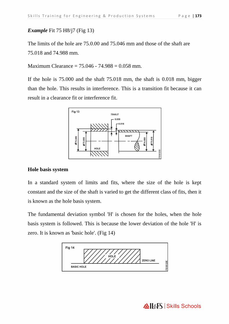
S k i l l s T r a i n i n g f o r E n g i n e e r i n g & P r o d u c t i o n S y s t e m s P a g e | 173
Example Fit 75 H8/j7 (Fig 13)
The limits of the hole are 75.0.00 and 75.046 mm and those of the shaft are
75.018 and 74.988 mm.
Maximum Clearance = 75.046 - 74.988 = 0.058 mm.
If the hole is 75.000 and the shaft 75.018 mm, the shaft is 0.018 mm, bigger
than the hole. This results in interference. This is a transition fit because it can
result in a clearance fit or interference fit.
Hole basis system
In a standard system of limits and fits, where the size of the hole is kept
constant and the size of the shaft is varied to get the different class of fits, then it
is known as the hole basis system.
The fundamental deviation symbol 'H' is chosen for the holes, when the hole
basis system is followed. This is because the lower deviation of the hole 'H' is
zero. It is known as 'basic hole'. (Fig 14)

P a g e | 174 O n l y F o r P r i v a t e C i r c u l a t i o n
Shaft basis system
In a standard system of limits and fits, where the size of the shaft is kept
constant and the variations are given to the hole for obtaining different class of
fits, then it is known as shaft basis. The fundamental deviation symbol 'h' is
chosen for the shaft when the shaft basis is followed. This is because the upper
deviation of the shaft 'h' is zero. It is known as 'basic shaft'
The hole basis system is followed mostly. This is because, depending upon the
class of fit, it will be always easier to alter the size of the shaft because it is
external, but it is difficult to do minor alterations to a hole. Moreover the hole
can be produced by using standard toolings. The three classes of fits, both under
hole basis and shaft basis, are illustrated in

S k i l l s T r a i n i n g f o r E n g i n e e r i n g & P r o d u c t i o n S y s t e m s P a g e | 175
THE BIS SYSTEM OF LIMITS AND FITS - READING THE
STANDARD CHART
The standard chart covers sizes upto 500 mm (IS. 919 of 1963) for both holes
and shafts. It specifies the upper and lower deviations for a certain range of
sizes for all combinations of the 25 fundamental deviations, and 18 fundamental
tolerances.
The upper deviation of the hole is denoted as ES and the lower deviation of the
hole is denoted as E I. The upper deviation of the shaft is denoted as es and the
lower deviation of the shaft is denoted as ei.
NOTE
ES is expanded as ECART SUPERIEUR and eias ECART INFERIEUR.
Determining the limits from the chart
Note whether it is an internal measurement or an external measurement.
Note the basic size.
Note the combination of the fundamental deviation and the; grade of tolerance.
Then refer to the chart and note the upper and lower deviations which are given
in microns, with the sign.
Accordingly add or subtract from the basic size and determine the limits of size
of the components.

P a g e | 176 O n l y F o r P r i v a t e C i r c u l a t i o n
Allowable deviations for dimensions without specified tolerances
15:2102-1969 Deviations for linear dimensions
Deviations for angular dimensions
Class of
devia-
tion
Above
Upto and
including
0.5 3 6 30 120 315 1000 2000 4000 5000 12000 16000
3 6 30 120 315 1000 2000 4000 8000 12000 16000 20000
Fine ±0.0
5
+0,05 ±0.1 ±0.15 +0.2 +0.3 ±0.5 +0.8 - - - -
medium ±0.1 ±0.1 +0.2 ±0.3 ±0.5 +0.8 ±1.2 +2 ±3 +4 ±5 ±6
Coarse - ±0.2 ±0.5 ±o:8 ±1.2 +2 ±3 ±4 ±5 ±6 ±7 ±8
Extra Coarse - ±0.5 ±1 ±1.5 ±2 ±3 ±4 +6 ±8 ±10 ±12 ±12
Length (L) of shorter side of angle in mm
- Angle tolerance
in angular units
Class of deviation.
Above 10 50 120
Upto and 10
including
50 120
Fine and medium
m (mm) ±0.1 ±0.2 ±0.6 +0.8
m (deg +1° or min) ±30' ±20' +10"
m Angle tolerance
in linear units
Coarse
m (mm) +0.15 ±0.3 +0.8 ±1.2
m (deg ±1.5° or
min)
±50' ±25' +15'
m (mm) +0.3 ±0.8 ±1.8 +2.4
Extra Coarse (deg +3° or min) ±2° ±1° ±30

S k i l l s T r a i n i n g f o r E n g i n e e r i n g & P r o d u c t i o n S y s t e m s P a g e | 177
Revision Of Last Day’s Lecture
Complete job
Complete job
Complete job
Complete job
DAY 28: 12.30 PM- 04.30 PM
DAY 28: 10:00 AM - 12.00 PM
DAY 27: 12.30 PM- 04.30 PM
DAY 27: 10:15 AM - 12.00 PM
DAY 27: 10:00 AM- 10:15 AM

P a g e | 178 O n l y F o r P r i v a t e C i r c u l a t i o n
REVISION OF THEORY (SELECTIVE)
Revision Of Important Theory Topics, Covered In All Prior Sessions
REVISION OF THEORY (SELECTIVE)
Revision Of Important Theory Topics, Covered In All Prior Sessions
THEORY ASSESSMENT FINAL
PRACTICAL ASSESSMENT FINAL
DAY 30: 12:30 AM - 04.30 PM
DAY 30: 10:00 AM- 12:00 AM
DAY 29: 12.30 PM- 04.30 PM
DAY 29: 10:00 AM- 12:00 AM