Embed Size (px)
Citation preview
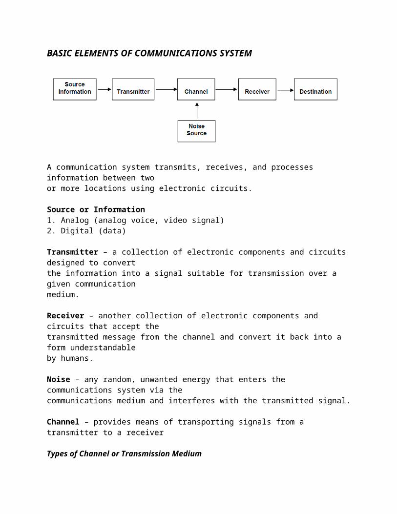
BASIC ELEMENTS OF COMMUNICATIONS SYSTEM
A communication system transmits, receives, and processes information between twoor more locations using electronic circuits.
Source or Information1. Analog (analog voice, video signal)2. Digital (data)
Transmitter – a collection of electronic components and circuits designed to convertthe information into a signal suitable for transmission over a given communicationmedium.
Receiver – another collection of electronic components and circuits that accept thetransmitted message from the channel and convert it back into a form understandableby humans.
Noise – any random, unwanted energy that enters the communications system via thecommunications medium and interferes with the transmitted signal.
Channel – provides means of transporting signals from a transmitter to a receiver
Types of Channel or Transmission Medium1. Pair of copper wires (electric current flow)2. Optical Fiber Cables (light waves)3. Free Space (radio waves)Radio Transmission makes use of electromagnetic spectrum where signals are

converted into electric and magnetic fields that propagate readily over long distances.
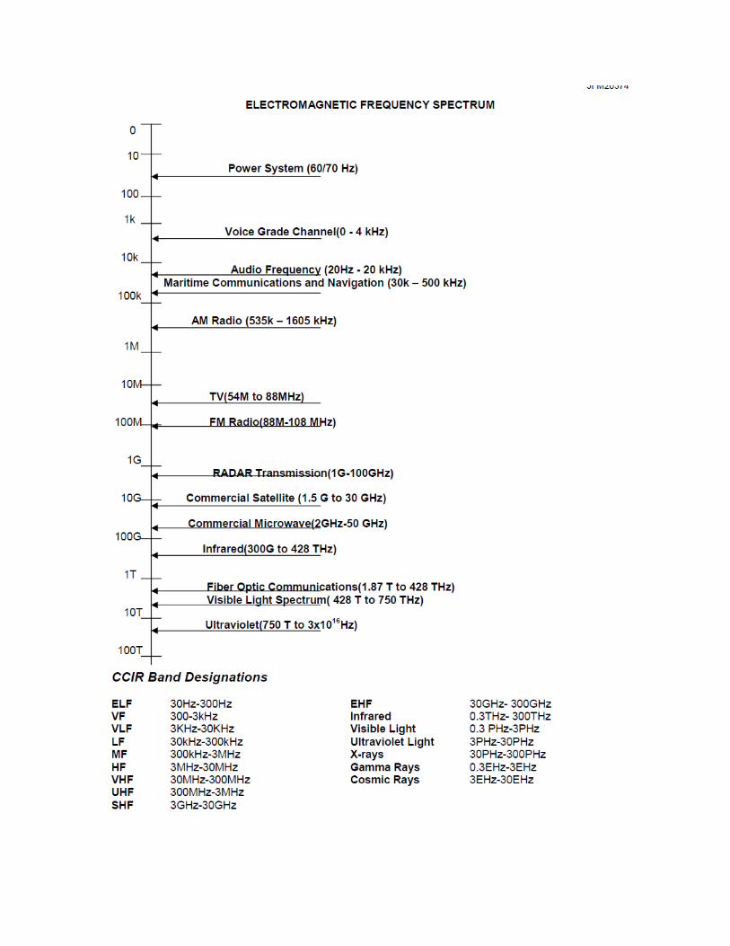
What is Microwave?A microwave is a signal with a frequency greater than 1 GHz. The microwaveregion may extend to 30 GHz, 300 GHz, and 600 GHz. High frequencies have relativelyshort wavelengths.Microwave communications is simply a high radio frequency link specificallydesigned to provide signal connection between 2 specific points. Also known as LOScommunications, radio links, Point-to-point communications.
CLASSIFICATIONS OF MICROWAVE COMMUNICATIONS
A. Nature1. Analog – FM, AM2. Digital – PSK or QAM
B. Distance/Frequency1. Short Haul2. Medium Haul3. Long Haul
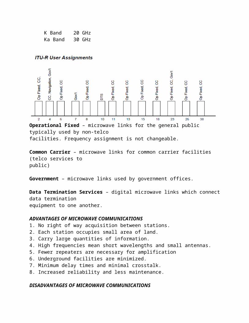
C. Capacity / Bandwidth1. Light (Narrow Band)2. Medium (Narrow Band)3. Large (Wide Band)Digital Voice is narrow band (4 KHz channel)Digitized TV Signal is wideband (6MHz video signal)
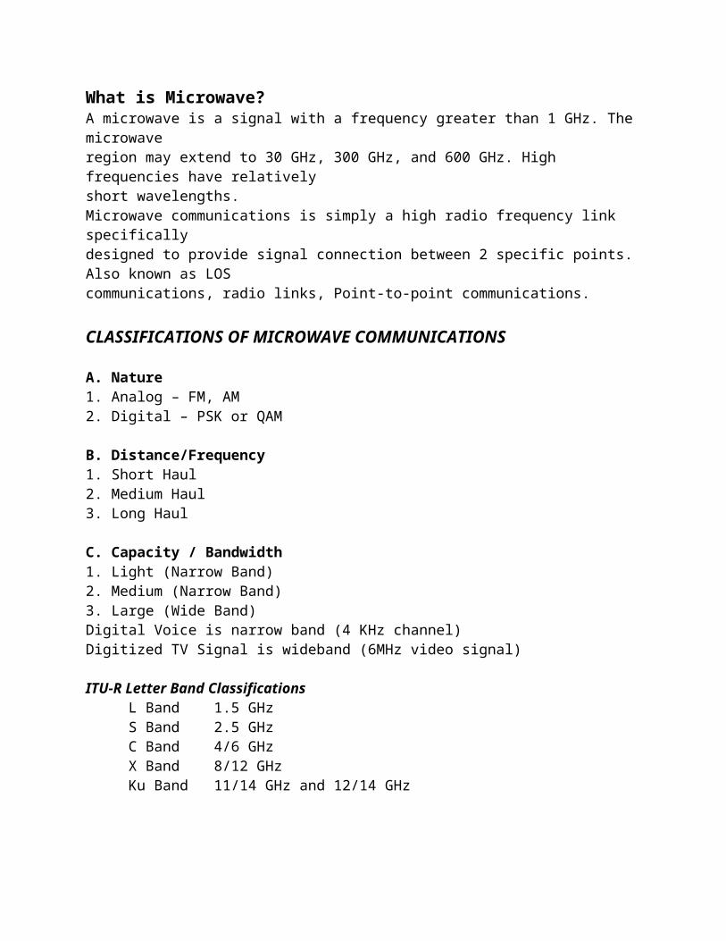
ITU-R Letter Band ClassificationsL Band 1.5 GHzS Band 2.5 GHzC Band 4/6 GHzX Band 8/12 GHzKu Band 11/14 GHz and 12/14 GHzK Band 20 GHzKa Band 30 GHz
Operational Fixed – microwave links for the general public typically used by non-telcofacilities. Frequency assignment is not changeable.
Common Carrier – microwave links for common carrier facilities (telco services topublic)
Government – microwave links used by government offices.
Data Termination Services – digital microwave links which connect data terminationequipment to one another.
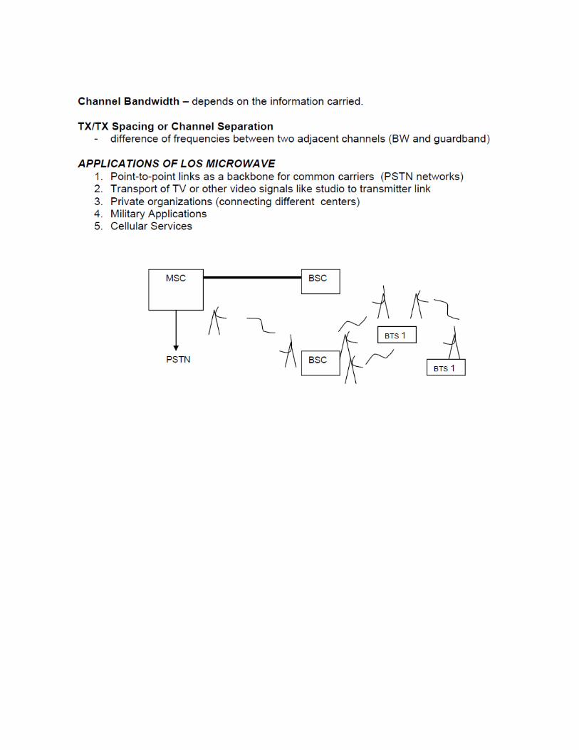
ADVANTAGES OF MICROWAVE COMMUNICATIONS1. No right of way acquisition between stations.2. Each station occupies small area of land.3. Carry large quantities of information.4. High frequencies mean short wavelengths and small antennas.5. Fewer repeaters are necessary for amplification6. Underground facilities are minimized.7. Minimum delay times and minimal crosstalk.8. Increased reliability and less maintenance.
DISADVANTAGES OF MICROWAVE COMMUNICATIONS1. Conventional components become more difficult to implement.2. Transit time in transistor devices is longer.3. Affected by atmospheric conditions.4. Straight line limits distance.

FM Deviator – provides modulation of the IF carrier that eventually becomes the mainmicrowave carrier.
Mixer – used to translate the IF frequencies into RF frequencies
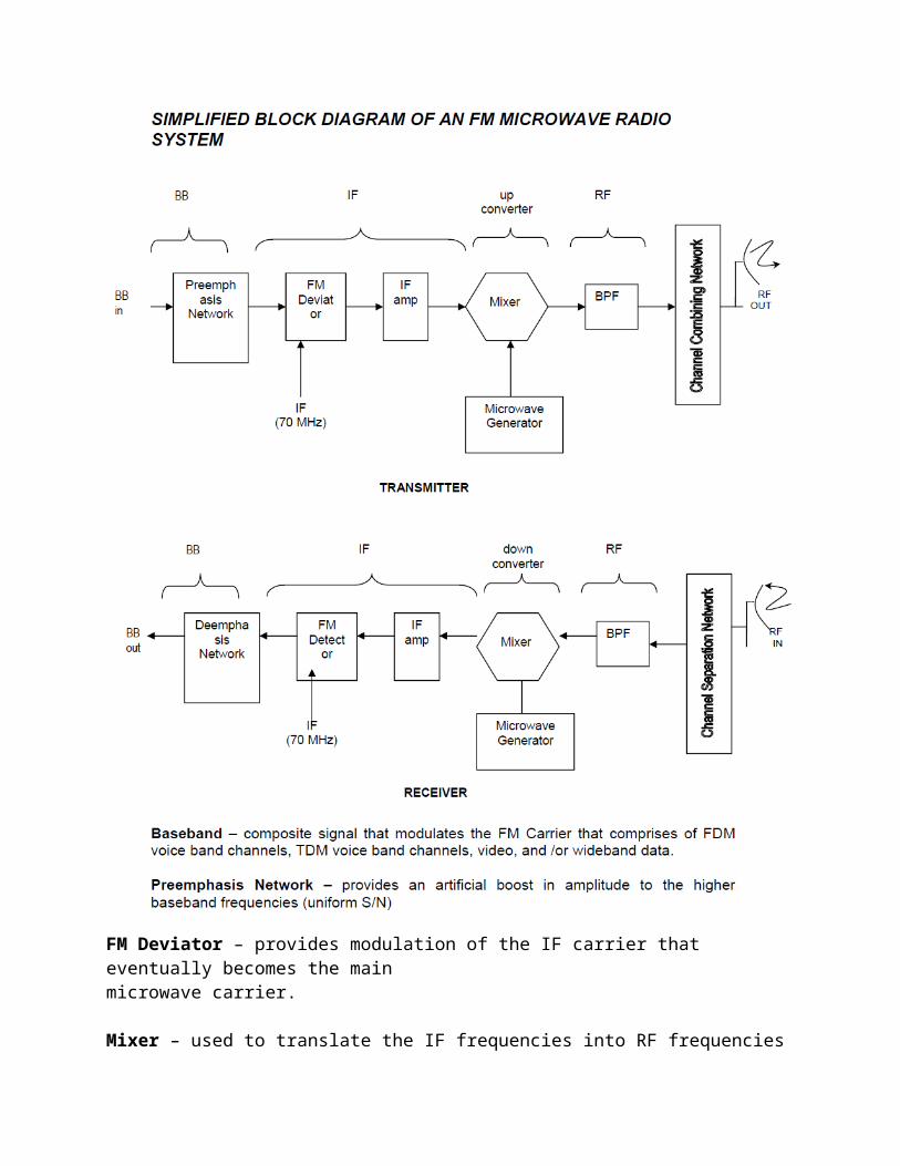
Microwave Generator – consists of a crystal oscillator and followed by a series offrequency multipliers. (125 MHz x 48 = 66 Hz)
Channel Combining Network – provides a means of connecting more than onemicrowave transmitter to a single transmission line feeding the antenna.
Channel Separation Network – provides the isolation and filtering necessary toseparate individual microwave channels and direct them to their respective receivers.
FM Detector – extracts baseband signal from the modulate wave.
Deemphasis Network – restores the baseband signal to its original amplitude vsfrequency characteristics.
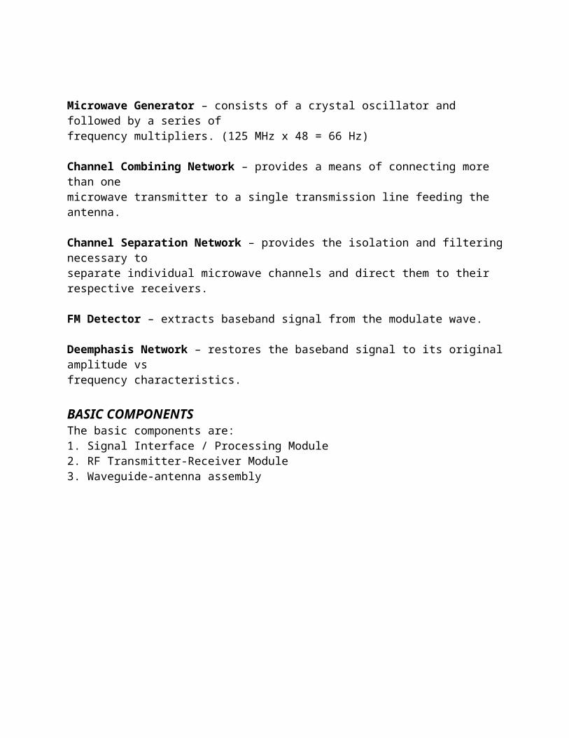
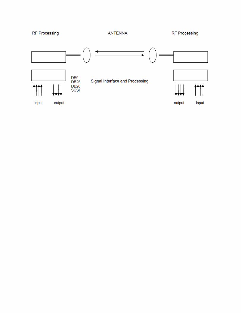
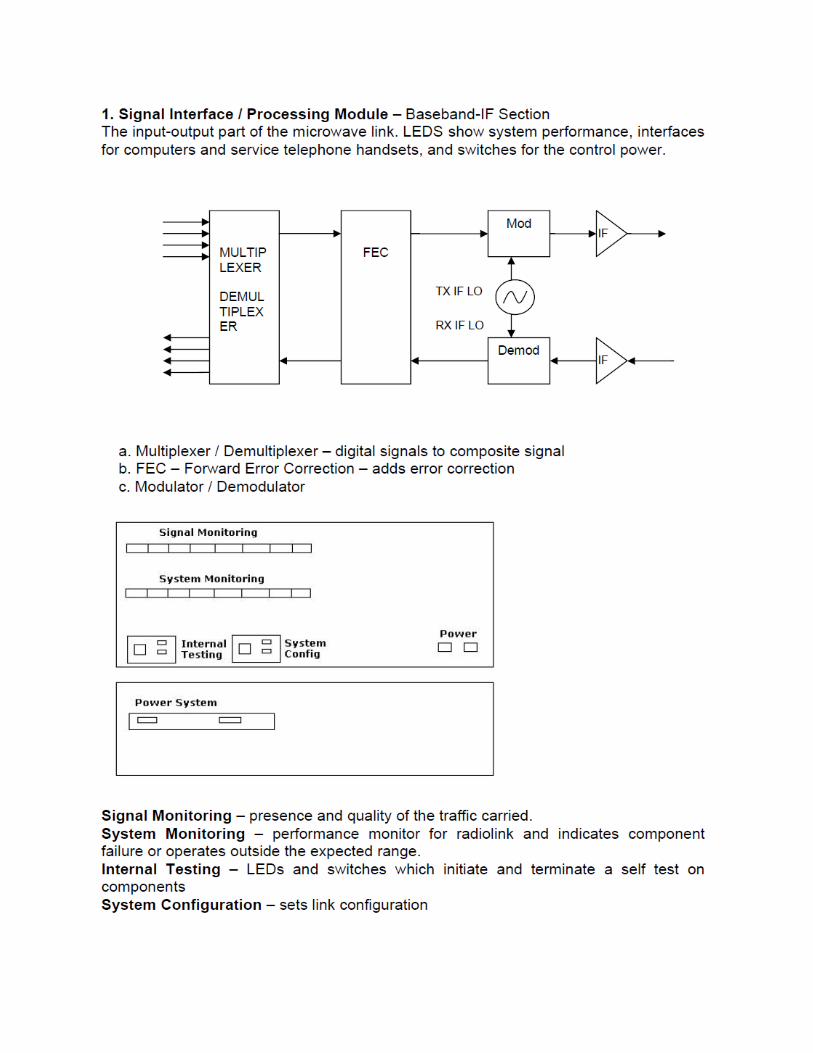
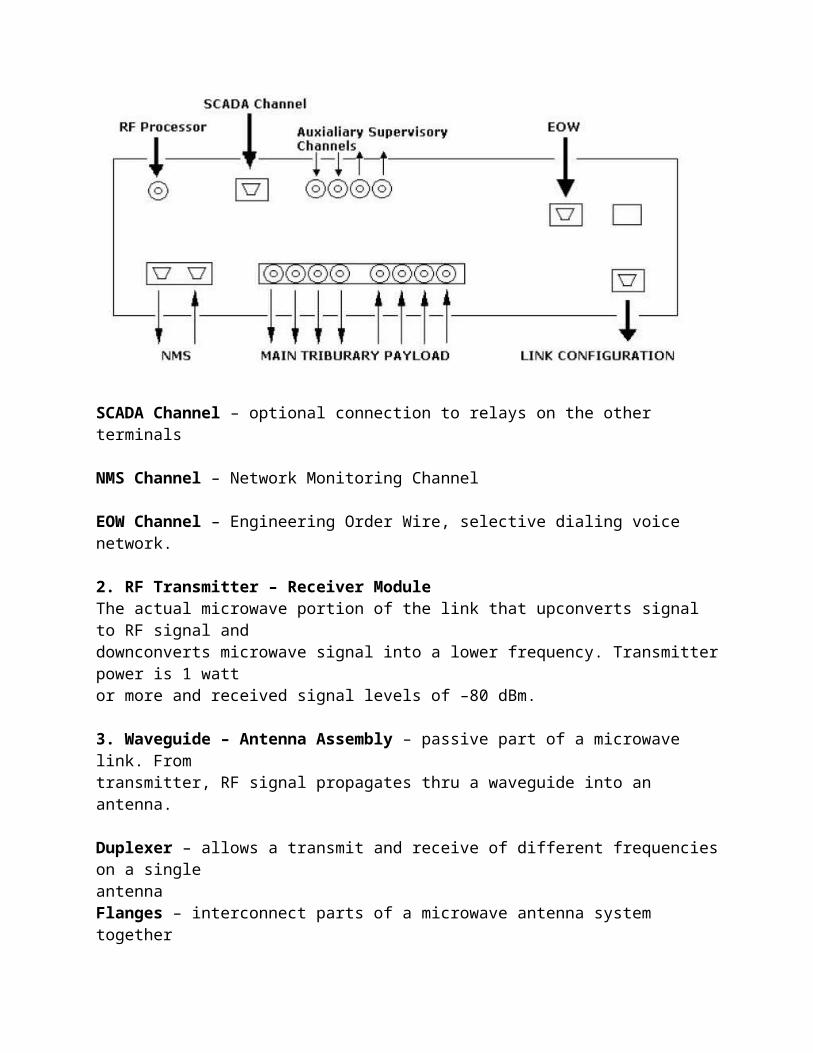
BASIC COMPONENTSThe basic components are:1. Signal Interface / Processing Module2. RF Transmitter-Receiver Module3. Waveguide-antenna assembly
SCADA Channel – optional connection to relays on the other terminals
NMS Channel – Network Monitoring Channel
EOW Channel – Engineering Order Wire, selective dialing voice network.
2. RF Transmitter – Receiver ModuleThe actual microwave portion of the link that upconverts signal to RF signal anddownconverts microwave signal into a lower frequency. Transmitter power is 1 wattor more and received signal levels of –80 dBm.
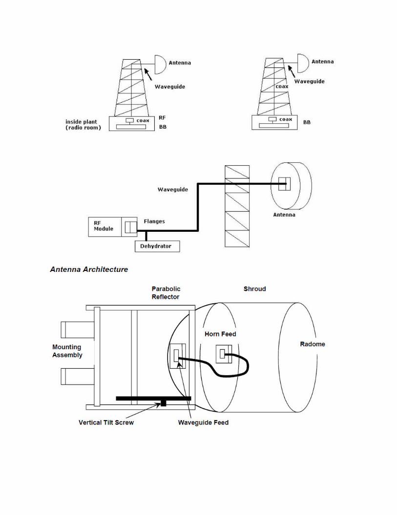
3. Waveguide – Antenna Assembly – passive part of a microwave link. Fromtransmitter, RF signal propagates thru a waveguide into an antenna.
Duplexer – allows a transmit and receive of different frequencies on a singleantennaFlanges – interconnect parts of a microwave antenna system together
Waveguide – hollow metal duct which allows antenna to be remotely installed awayfrom a transmitter and receiver
Dehydrator – pumps clean dry air into the waveguide and / or RF module. Waterdroplets in the waveguide cause losses in the signal.
Waveguide feed – connects the antenna to the waveguide
Horn Feed – directs the electromagnetic wave into the focus of the parabolicreflector
Parabolic Reflector – reflective surface of the parabolic dish
Radome – front covering of the antenna. Protects inside surface
Shroud – side covering of the antenna. Reduces interference from otherantennas
Mounting Assembly – clamps the antenna to the mast or tower. Allows antennato be swung from left to right.
Vertical Tilt Screw – allows antenna to be pointed upward or downward
Other Components:1.) Towers – guyed or self-supporting towers2.) Buildings – equipment should be located inside3.) Primary and Secondary Power – batteries, generators, fuel cell, solar energy,AC power4.) Alarm systems
ANTENNA TOWERSThere are two types of towers used for LOS microwave systems:1.) Guyed - can be placed closer to a building and needs space.2.) Self-supporting - expensiveTowers are made of galvanized steel and tower foundations should be reinforcedconcrete with anchor bolts firmly embedded.
Tower considerations/Limitations1.) Economy or cost limits tower heights to 300 ft.2.) Real Estate3.) Proximity to airports or air lanes.4.) Soil conditions-increasing the foundation area increases soil bearing pressure.(4000 lb/ft2)
a.) EIA RS-222A/B defines “standard soil”.b.) Very rocky, difficult excavation, more large bases needed.
5.) Wind Loading-“design” or “elastic limit” (30 lb/ft2)
a.) Tower may sway or twist, degrading signal. (10dB)b.) To reduce sway and twist, tower rigidity must be improved.c.) Increase guys at the top of the tower.d.) Ice formation on towers and antennas.
6.) Local building codes and restrictionsa.) Roof mounted towers-consider structural adequacy of building.b.) Painting, markings and lighting.
LAND AREA REQUIREMENTS
3-Leg Self-Supported Tower DimensionsHeight in Feet R (feet) W (feet) H (feet)
25 9.5 17.3 16.150 13.8 26.6 23.4100 17.3 33.5 29.3150 21.9 42.0 37.1
4-Leg Self-Supported Tower DimensionsHeight in Feet R (feet) P (feet)
50 15.4 21.875 17.8 25.3100 20.5 28.9150 25.4 35.9
RADIO EQUIPMENTRadio equipments used for microwave systems can be relatively small for light routes ormay be very heavy, requiring multi-channel, heavy route layout with sophisticatedswitching. Its operation may be on certain limited hours of the day or on a 24-hour aday, year-in and year-out.
Types of microwave systems:
1. Through – all or almost all of the channels going end-to-end.2. Drop and Insert – requires multiple access, with dropping and inserting ofchannels at most repeater points.
Types of FM Microwave Equipment:1. IF heterodyne – RF carrier is down-converted to an IF frequency
a. Eliminated demodulation and remodulation steps at repeaters.b. Contributes the least among of distortion.c. Used for long-haul traffic, with little requirement for drop and insert
alongthe route.d. Color TV traffic
2. Baseband or Remodulating – RF carrier is down-converted to an IF frequencyand further demodulated to baseband.
a. Widely used for short-haul or for distributive systems in the telephone
industry.b. Flexible for drop and insert and maintenance advantages.
Selection criteria of the Best Radio Equipment1. Characteristic of the end-to-end baseband facility
a. Bandwidthb. Frequency Response
c. Loading Capabilityd. Noise Figuree. Noise Performance
2. Amount of Radio Gain Availablea. Transmitter Power Outputb. Receiver Noise Characteristics
3. Operating Frequency Band and Required Frequencya. Transmitter deviationb. Receiver Selectivityc. Frequency Stability (Receive)
4. Primary Power Requirements and Options5. Supervisory Functions Available
a. Order Wireb. Alarms and Controls
6. Equipment Reliabilitya. Frequency Diversityb. 1-for-N or 2-for-N multiline switching or hot-standby at transmittersc. Space Diversity at Receivers
7. Provisions for Testing and Maintenance