Embed Size (px)
Citation preview

Basic Electronic Circuits
+

Final Design Challenge: Situation
The “Drive Thru Family Laundry” is along a busy road.
The facility is set back from the road so that it has a drive thru for customer convenience.
The Store is designed so that it has two main sectionsOffice in frontLaundry in back
Laundry
Office
Drive Thru
Main Road

Design Challenge: ProblemsSometimes only one person is working in the
store.The laundry is noisy and it is sometimes difficult
for workers to hear / see when customers arrive.Several customers have complained lately
because they pull up to the drive thru and they have to wait because the workers do not know they are there.
Workers have complained because they are busy and have to hurry back and forth between the laundry and office to see if customers are waiting.

Design ChallengeUsing the materials provided, design an
alarm system that will alert the workers when someone drives up to the store
MaterialsLightsBuzzerMotorWiresBatteriesVarious conductors and insulatorsConstruction Materials
Cardboard, paper, tape

Challenge #1Given the following resources, light the bulb!
A battery, a bulb and a jumper wire
When you are successful, draw a picture of how you connected your circuit in your notebook and then sign off with the teacher.

Minds of Our Own Video

If you look close in the video, you will notice that the students connected the circuit like this.
Why won’t this work??
BatteryBattery_
+
Open Circuit!!!
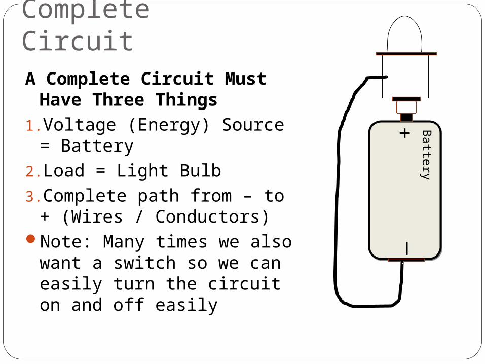
Complete CircuitA Complete Circuit Must
Have Three Things1.Voltage (Energy) Source =
Battery2.Load = Light Bulb3.Complete path from – to +
(Wires / Conductors)Note: Many times we also
want a switch so we can easily turn the circuit on and off easily
Battery
Battery
_+

Representing CircuitsQuestions: What are some ways we could
communicate to others how to put this circuit together?
Answer: Draw a picture, take a pictureWhen working with electronic circuits,
engineers and technicians use symbols to represent the different components in a circuit. These symbols are called schematic symbols.
FM Wireless Microphone
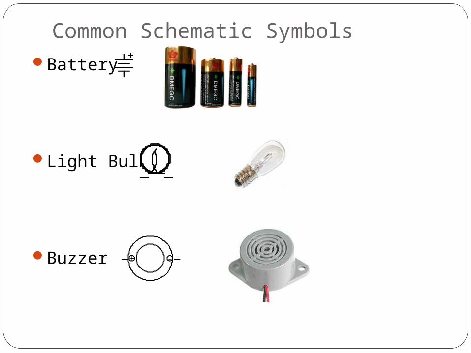
Common Schematic SymbolsBattery
Light Bulb
Buzzer
+
+ -

Switches
Normally Open
Normally Closed
SPST (Single Pole, Single Throw)
SPDT (Single Pole, Double Throw)

GeneralFuse
Wire Crossing not connected
Wires Crossing & Connected
1A

The Circuit From Challenge #1
BatteryBattery_
+
+

Note to teacherWhen teaching the following section you can use the
ppt and formally take the students step by step through all the challenges….
OR…. What I recommend – informally make up/draw the challenges with the students as you go.
Some challenges to considerAdd a switchWhat would happen if we added another battery?What would happen if we added another light in series?Switch up the arrangement of the series circuit to see if this has
an effect on the operation of the circuit? Does it matter where we put the components in series??
Switch the bulbs so they are in parallel – what happens?What would happen if we added a buzzer to the circuit?Will this same circuit (with buzzer) work in series? Let’s try it?
Note: try to present the material in such a way that they just see relationships and you don’t have to explain Ohm’s law at this time – save that for later.

Challenge #2Have one person from your group get the
components needed.Draw the circuit in your notebookTell me what you think will happen in this
circuit: Will the bulb light up?Build the circuitCheck off with the teacher +

Challenge #3Have one person from your group get the
components needed.Draw the circuit in your notebookTell me what you think will happen in this
circuit: Will the bulbs be brighter, less bright, remain the same?
Build the circuitCheck off with the teacher
+

Ohm’s LawTerm Description Symbol Unit of
Meas. Symbol
Charge Quantity of Accumulated Electrons Q Coulombs C
Voltage Electromotive Force E/V Volts V
Current Rate of Electron Flow I Amps A
Resistance Opposition to Electron Flow R Ohms Ω

Ohm’s Law
The amount of water (current) that will flowThrough the dam is determined by the force(height of the water) and how much we have opened the floodgates (resistance) of the dam.
The amount of current that will flow in a circuit is determined by the force (voltage of the battery) and the resistance of the loads (light bulbs).Since we have increased the bulbs from one to two, we have increased the resistance. Less current will thus flow and the bulbs are not as bright
+
+
IVR=
CurrentVoltage
Resistance=

Challenge #4What do you think will happen in this
circuit? Will the bulbs be brighter, less bright, remain
the same?Have one person from your group get the
additional component needed.Draw the circuit in your notebookNotice the polarities of the batteryBuild the circuitCheck off with the teacher
+ +

Challenge #5
What do you think will happen in this circuit? Will the bulbs be brighter, less bright, remain
the same?Draw the circuit in your notebookNotice the polarities of the batteryBuild the circuitCheck off with the teacher + +

These circuits are the same: Both are called series circuits
+ +
+ +

Challenge 6What do you think will happen in this
circuit? Will the bulbs be brighter, less bright, remain
the same?Draw the circuit in your notebookNotice the polarities of the batteryBuild the circuitCheck off with the teacher
+ +

Challenge #7What do you think will happen in this circuit?
Will the bulb be brighter, less bright, remain the same?Will the buzzer work?
Draw the circuit in your notebookNotice the polarity of the buzzerBuild the circuitCheck off with the teacher
What do you think would happen if we put the buzzer and light bulb in series???
+ -
+

Checking For UnderstandingFor the following circuits, determine:
1. If the bulb(s) will light2. If the bulbs will be dim, average brightness,
or very bright.+
+ +
+ +A)
C) D)
B)

Checking For UnderstandingFor the following circuits, determine:
1. If the bulb(s) will light2. If the bulbs will be dim, not light or be
brightA)
C)
B)
+
+ +
+

Design Challenge: Situation
The “Drive Thru Family Laundry” is along a busy road.
The facility is set back from the road so that it has a drive thru for customer convenience.
The Store is designed so that it has two main sectionsOffice in frontLaundry in back
Laundry
Office
Drive Thru
Main Road

Design Challenge: ProblemsSometimes only one person is working in the
store.The laundry is noisy and it is sometimes difficult
for workers to hear / see when customers arrive.Several customers have complained lately
because they pull up to the drive thru and they have to wait because the workers do not know they are there.
Workers have complained because they are busy and have to hurry back and forth between the laundry and office to see if customers are waiting.

Design Challenge
Using the materials provided, design an alarm system that will alert the workers when someone drives up to the store
MaterialsLightsBuzzerMotorWiresBatteriesVarious conductors and insulatorsConstruction Materials
Cardboard, paper, tape

Engineering Design Cycle: Boston Museum of Science

Procedure1. Put students in groups of two or three; 2. On paper design a circuit that will activate the alarm
when the someone drives up to the business. Create a pictorial diagram of your switch including a
materials list. Draw your schematic diagram, plan and create a
materials list of the parts needed to build the circuit.3. Have the teacher check your circuit and your switch to
make sure that your design is safe.4. Build and test the alarm circuit to make sure it works!5. Make any improvements to your design you want to
make. Note: If you make improvements to your circuit, then make sure you change your schematic and materials list.
6. Next, take apart your circuit so that nothing is connected.
7. Build the store (office & laundry) but don’t wire it yet.

Engineering Design Process: Electronic Circuits - Alarm Lab
ASK: What is the problem? What can I do to sense when
someone drives up to the store
What type of circuit will I need for the alarm to be activated
What makes a circuit complete.
Should I use series or parallel or both?
What other types of alarms am I familiar with?
Do we want to use both a light and a buzzer?
What type of switch can I use?
What are the constraints? What materials do I have? What is the cost? Is my circuit safe? Is there a size limitation?
IMAGINE: What are some possible
solutions? Brainstorm ideas. Choose the one you
think is best. PLAN:
Draw a schematic diagram,
Make lists of materials you will need.
CREATE: Follow your plan and
create it, Test it out!
IMPROVE: Talk about what works,
what doesn't, and what could work better,
Modify your design to make it better, test it out!

Procedures: ContinuedGive your components and the schematic
drawings with the parts list to another group.
If you have documented your work really well then the other groups should be able to build your alarm circuit.