Embed Size (px)
Citation preview

LABORATORY DETAILS
DEPARTMENT OF ELECTRICAL ENGINEERING
BASIC ELECTRICAL ENGINEERING LABORATORY (ESEE191)
Sl
No Name of the Experiment Equipment No. Of Set Up
1
Introduction to basic safety precautions and
mentioning of the do’s and Don’ts. Noting
down list of experiments to be performed, and
instruction for writing the laboratory reports by
the students. Group formation. Students are to
be informed about the modalities of evaluation.
Available
2
Introduction and uses of following instruments :
(a) Voltmeter
(b) Ammeter
(c) Multimeter
(d) Oscilloscope
Demonstration of real life resistors, capacitors with color code , inductors and autotransformer
Voltmeter,Ammeter
Oscilloscope, Multimeter
available
3
Demonstration of cut-out sections of machines:
DC machine, Induction machine, Synchronous
machine and single phase induction machine.
Cut sections of DC machine available
1
4 Calibration of ammeter and Wattmeter Experimental Setup 1
5
A) Open circuit and short circuit test of a single phase transformer
B) Load test of the transformer and determination of efficiency and regulation
Experimental Setup 1
6 Measurement of power in a three phase unbalanced circuit by two wattmeter method.
Experimental Setup with Resistive Load
1
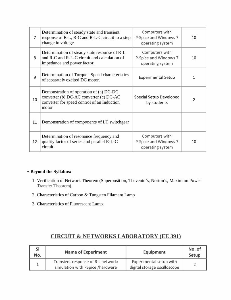
7
Determination of steady state and transient
response of R-L, R-C and R-L-C circuit to a step
change in voltage
Computers with P-Spice and Windows 7
operating system
10
8
Determination of steady state response of R-L
and R-C and R-L-C circuit and calculation of
impedance and power factor.
Computers with P-Spice and Windows 7
operating system
10
9 Determination of Torque –Speed characteristics
of separately excited DC motor. Experimental Setup 1
10
Demonstration of operation of (a) DC-DC
converter (b) DC-AC converter (c) DC-AC
converter for speed control of an Induction
motor
Special Setup Developed by students
2
11 Demonstration of components of LT switchgear
12
Determination of resonance frequency and
quality factor of series and parallel R-L-C
circuit.
Computers with P-Spice and Windows 7
operating system
10
• Beyond the Syllabus:
1. Verification of Network Theorem (Superposition, Thevenin’s, Norton’s, Maximum Power
Transfer Theorem).
2. Characteristics of Carbon & Tungsten Filament Lamp
3. Characteristics of Fluorescent Lamp.
CIRCUIT & NETWORKS LABORATORY (EE 391)
Sl No.
Name of Experiment Equipment No. of Setup
1 Transient response of R-L network: simulation with PSpice /hardware
Experimental setup with digital storage oscilloscope
2

2 Transient response of R-C network: simulation with PSpice /hardware
3
Transient response of R-L-C series circuit: simulation with PSpice/
hardware
Experimental setup with CRO
2
4
Determination of impedance (z) and admittance (y) parameter of two port
network: simulation/hardware
Experimental setup 2
5 Frequency response of low pass and
high pass filters: simulation / hardware Experimental setup 2
6
Generation of periodic, exponential, sinusoidal, damped sinusoidal, step,
impulse, ramp signal using MATLAB in both discrete and analog form
Computers with MATLAB, PSpice and Windows 7
operating system
10 7 Determination of laplace transform and inverse laplace transform using MATLAB
8 Amplitude and phase spectrum analysis
of different signals using MATLAB
9 Verification of network theorem using
PSpice
• Beyond the Syllabus:
1. Determination of ABCD and h parameters of a two port network.
2. Representation of poles and zeros in s-plane, determination of partial function expansion in
s-domain and cascade connection of second order systems using MATLAB.
3. Amplitude and phase spectrum analysis of different signals using MATLAB.
ELECTRIC MACHINE - I LABORATORY (EE 491)
Sl No.
Name of Experiment Equipment No. of Setup
1 Study of the characteristics of a separately excited dc generator
Separately excited dc generator with complete
experimental setup
1

2 Study of the characteristics of a dc
shunt motor
Dc shunt motor with complete experimental
setup
1
3 Study of methods of speed control of dc
shunt motor
Dc shunt motor with complete experimental
setup
1
4 Study of the characteristics of a
compound dc generator (short shunt)
Compound dc generator (short shunt) with complete
experimental setup
1
5 Measurement of speed of dc series motor as a function of load torque
Dc series motor with complete experimental
setup
1
6 Study of equivalent circuit of a single
phase transformer
Single phase transformer with complete
experimental setup
1
7
Polarity test on a single phase transformer & study of different
connections of three phase transformer
3 single phase transformer with complete
experimental setup
1
8
Study of equivalent circuit of three phase induction motor by no load and
blocked rotor test
Three phase induction motor with complete experimental setup
1
9 Study of performance of wound rotor
induction motor under load
Wound rotor induction motor with complete experimental setup
1
10
Study of performance of three phase squirrel- cage induction motor –
determination of Iron-loss, friction & windage loss
Three phase squirrel- cage induction motor
1
• Beyond the Syllabus:
1. Study of external characteristics of dc shunt generator.
2. Mathematical modelling of dc machines.
ELECTRICAL & ELECTRONIC MEASUREMENT LABORATORY
(EE 492)
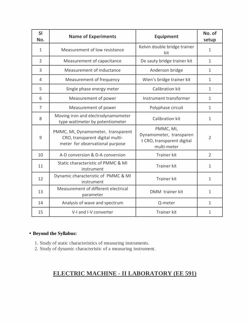
Sl No.
Name of Experiments Equipment No. of setup
1 Measurement of low resistance Kelvin double bridge trainer
kit 1
2 Measurement of capacitance De sauty bridge trainer kit 1
3 Measurement of inductance Anderson bridge 1
4 Measurement of frequency Wien’s bridge trainer kit 1
5 Single phase energy meter Calibration kit 1
6 Measurement of power Instrument transformer 1
7 Measurement of power Polyphase circuit 1
8 Moving iron and electrodynamometer
type wattmeter by potentiometer Calibration kit 1
9
PMMC, MI, Dynamometer, transparent CRO, transparent digital multi-
meter for observational purpose
PMMC, MI, Dynamometer, transparent CRO, transparent digital
multi-meter
2
10 A-D conversion & D-A conversion Trainer kit 2
11 Static characteristic of PMMC & MI
instrument Trainer kit 1
12 Dynamic characteristic of PMMC & MI
instrument Trainer kit 1
13 Measurement of different electrical
parameter DMM trainer kit 1
14 Analysis of wave and spectrum Q-meter 1
15 V-I and I-V converter Trainer kit 1
• Beyond the Syllabus:
1. Study of static characteristics of measuring instruments.
2. Study of dynamic characteristic of a measuring instrument.
ELECTRIC MACHINE - II LABORATORY (EE 591)

Sl No.
Name of Experiment Equipment No. of Setup
1
Different methods of starting of a 3 phase cage induction motor & their
comparison [dol, auto transformer & star-delta]
3 phase squirrel cage induction motor [dol, auto transformer & star-delta
starter]
1
2
Speed control of 3 phase squirrel cage induction motor by different methods &
their comparison [voltage control & frequency control]
3 phase squirrel cage induction motor with
complete experimental setup
1
3
Speed control of 3 phase slip ring induction motor by rotor resistance
control
3 phase slip ring induction motor with complete experimental setup
1
4
Determination of regulation of synchronous machine by potier
reactance method
Synchronous alternator – dc shunt motor with
complete experimental setup
1
5
Determination of regulation of synchronous machine by synchronous
impedance method
Synchronous alternator – dc shunt motor set with
complete setup
1
6
Determination of equivalent circuit parameters of a single phase induction
motor
Single phase induction motor
1
7
Load test on single phase induction motor to obtain the performance
characteristics
Single phase induction motor
1
8
To determine the direct axis reactance [xd] & quadrature axis reactance [xq] of a 3 phase synchronous machine by slip
test
Synchronous alternator – dc shunt motor set with
complete setup
1
9
Load test on wound rotor induction motor to obtain the performance
characteristics
Wound rotor induction motor
1
10
To make connection diagram to full pitch & fractional slot winding of 18 slot
squirrel cage induction motor for 6 poles & 4 pole operation
Induction motor for 6 poles & 4 pole operation
1
11 To study the performance of induction
generator Induction generator 1
12 Parallel operation of 3 phase
synchronous generators
3 phase synchronous generators
1

13 V-curve of synchronous motor Synchronous motor 1
• Beyond the Syllabus:
1. Study of torque-speed characteristics of three phase asynchronous machines using
MATLAB.
2. Study of position control using dc servomotor.
POWER SYSTEM - I LABORATORY (EE 592)
Sl No.
Name of Experiment Equipment No. of Setup
1
Determination of the generalized constants A, B, C, D of long transmission
line
Complete experimental setup with T/pie network
and phase angle meter 1
2 Simulation of dc distribution by network
analyzer
Network analyzer with complete experimental
setup
1
3 Measurement of earth resistance by
earth tester Earth resistance tester 1
4 Dielectric strength test of insulating oil Sphere gap arrangement 1
5 Determination of breakdown strength
of solid insulating material Complete experimental
setup 1
6 Different parameter calculation by
power circle diagram
Complete experimental setup with T/pie network,
phase angle meter, tri vector meter
1
7 Study of different types of insulator Suspension disc, pin,
shackle 1
8 Active and reactive power control of
alternator
Dc shunt motor-alternator set, with complete experimental setup
1
9 Dielectric constant, tan delta, resistivity
test of transformer oil
Complete experimental setup for measurement of
dielectric loss angle of transformer oil
1

• Beyond the Syllabus:
1. Determination of insulation strength of paper.
2. Study of Ferranti effect using MATLAB/SIMULINK.
CONTROL SYSTEMS - I LABORATORY (EE 593)
No. Name of Experiments Equipment No. of setup
1
Familiarization with MATLAB control system tool box, MATLAB simulink tool
box & PSpice
Computer with Windows 7 operating system
and MATLAB and PSpice software
10
2
Determination of step response for first order & second order system with unity
feedback on CRO & calculation of control system specification like time constant, % peak overshoot, settling
time etc. from the response
3
Simulation of step response & impulse response for type-0, type-1 & type-2
system with unity feedback using MATLAB & PSpice
4
Determination of root locus, bode plot, nyquist plot using MATLAB control
system tool box for 2nd order system & determination of different control system specification from the plot
5
Determination of PI, PD and PID controller action of first order simulated
process
PID controller, DSO 1

6
Tuning of P, PI, and PID controller for first order plant with dead time using z-
n method. Process parameters (time constant and delay/lag) will be
provided, the students would compute controller gains by using z-n method.
Steady state and transient performance of the closed loop plant with and
without steady disturbances will have to be noted. Theoretical phase and gain
margins will have to be manually computed for each gain settings
PID controller, DSO 1
7 Determination of approximate transfer
functions experimentally from bode plot
Computer with windows 7 operating system
and MATLAB and PSpice software
10
8
Evaluation of steady state error, setting time , percentage peak overshoot, gain margin, phase margin with addition of
lead compensator & by compensator in forward path transfer function for unity feedback control system using PSpice or
otherwise
9
Study of a practical position control system. Obtaining closed step responses for gain setting corresponding to over-damped and under-damped responses.
Determination of rise time and peak time using individualized components in simulink. Determination of un-damped natural frequency and damping ratio
from the experimental data
10
Design of lead and lag compensation using cascade tools (plant transfer
function will be provided. Step response is to be obtained
Linear system simulator and DSO, Compensation
design – 1
2,2,1
• Beyond the Syllabus:
1. Study of transient response analysis of dc motor using MATLAB/SIMULINK.
2. Compensator design using MATLAB.

CONTROL SYSTEMS - II LABORATORY (EE 691)
No. Name of Experiments Equipment No. of setup
1
State variable analysis using cascade command tool. Familiarization and use of cascade command for state variable
analysis. Obtaining transfer function from SV model and vice versa. Obtaining step response for a SISO system given in
SV form
Computer with windows 7 operating system
and MATLAB and PSpice software
10
2
State variable analysis using cascade block diagram tool familiarization and use of cascade block diagram tool for state variable analysis. Obtaining step
response and initial condition response for a single input, two output system
given in SV form
Computer with windows 7 operating system
and MATLAB and PSpice software
3
Performance analysis of a discrete time system using cascade tool.
Familiarization and use of cascade block diagram tool for digital control system.
Study of closed response of a continuous system with a digital controller with sample and hold
Ac, dc position control and motor unit
1,1,2
4
Studying the effects of nonlinearity in a feedback controlled system using time
response. Determination of step response with a limiter nonlinearity
introduced into the forward path of 2nd order unity feedback control systems. The open loop plant will have one pole at the origin and the other pole will be
in LHP or RHP. To verify that (i) with open loop stable pole, the response is
slowed down for larger amplitude input and (ii) for unstable plant, the closed loop system may become oscillatory
with large input amplitude
Computer with windows 7 operating system and MATLAB and PSpice
software
10
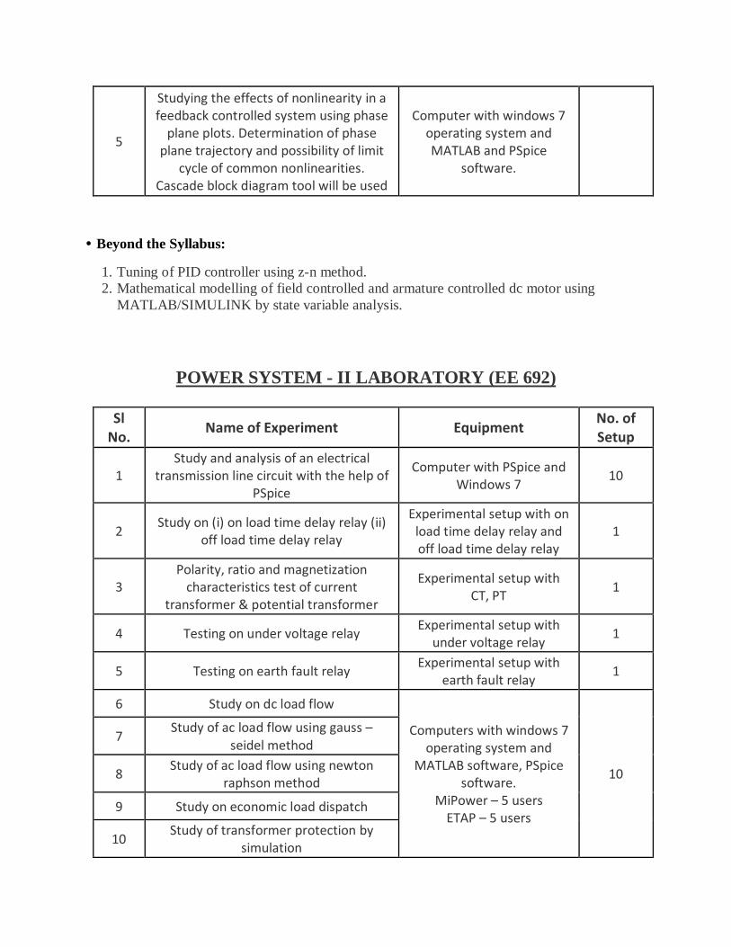
5
Studying the effects of nonlinearity in a feedback controlled system using phase
plane plots. Determination of phase plane trajectory and possibility of limit
cycle of common nonlinearities. Cascade block diagram tool will be used
Computer with windows 7 operating system and MATLAB and PSpice
software.
• Beyond the Syllabus:
1. Tuning of PID controller using z-n method.
2. Mathematical modelling of field controlled and armature controlled dc motor using
MATLAB/SIMULINK by state variable analysis.
POWER SYSTEM - II LABORATORY (EE 692)
Sl No.
Name of Experiment Equipment No. of Setup
1
Study and analysis of an electrical transmission line circuit with the help of
PSpice
Computer with PSpice and Windows 7
10
2 Study on (i) on load time delay relay (ii)
off load time delay relay
Experimental setup with on load time delay relay and off load time delay relay
1
3
Polarity, ratio and magnetization characteristics test of current
transformer & potential transformer
Experimental setup with CT, PT
1
4 Testing on under voltage relay Experimental setup with
under voltage relay 1
5 Testing on earth fault relay Experimental setup with
earth fault relay 1
6 Study on dc load flow
Computers with windows 7 operating system and
MATLAB software, PSpice software.
MiPower – 5 users
ETAP – 5 users
10
7 Study of ac load flow using gauss –
seidel method
8 Study of ac load flow using newton
raphson method
9 Study on economic load dispatch
10 Study of transformer protection by
simulation

11 Study of generator protection by
simulation
12 Study of motor protection by MiCOM
relay
Experimental setup with MiCOM relay
1
13 Study of different characteristics of over
current relay
Experimental setup with over current relay
1
• Beyond the Syllabus:
1. Study of CT saturation characteristics.
2. Symmetrical fault analysis using Mi-Power.
POWER ELECTRONICS LABORATORY (EE 693)
Sl No.
Name of Experiment Equipment No. of Setup
1 Study of the characteristics of an SCR Trainer kit 1
2 Study of the characteristics of a TRIAC Trainer kit 1
3 Study of different triggering circuits of
SCR Trainer kit 1
4
Study of firing circuits suitable for triggering SCR in a single phase fully
controlled bridge converter Trainer kit 1
5 Study of the operation of single phase
fully controlled bridge converter Trainer kit 1
6
Study of single phase half controlled symmetrical and asymmetrical bridge
converters
Trainer kit 1
7 Study of step down chopper Trainer kit 1
8
Simulation of single phase controlled converter with & without the source
inductance
Computers with operating system windows 7 and
PSIM
10
9 Simulation of step up and step down
chopper with MOSFET and GTO

10
Simulation of single phase half controlled symmetrical and
asymmetrical bridge converters
11 Simulation of PWM bridge inverter
using MOSFET with R-L load
12 Simulation of three phase ac regulator
• Beyond the Syllabus:
1. Study of VSI fed induction motor drive using PSIM software.
2. Study of BLDC motor drive with 6 pulse operation using PSIM software.
ELECTRIC DRIVES LABORATORY (EE 791)
Sl No.
Name of Experiment Equipment No. of Setup
1 Study of thyristor controlled dc drive Experimental setup with dc
motor 1
2 Study of chopper fed dc drive Experimental setup with dc
motor 1
3 Study of ac single phase motor-speed
control using TRIAC
Experimental setup with ac motor
1
4
PWM inverter fed 3 phase induction motor control using PSpice / MATLAB /
PSIM software
Computers with windows 7 and PSIM software
10 5
VSI / CSI fed induction motor drive analysis using PSpice / MATLAB / PSIM
software
6
Study of permanent magnet synchronous motor drive fed by PWM
inverter using software
7 Study of v/f control operation of 3
phase induction motor drive
Experimental setup with 3 phase induction motor and
v/f drive
1

8
Regenerative / dynamic braking operation for dc motor - study using
software
Experimental setup with dc motor
1
9
Regenerative / dynamic braking operation of ac motor - study using
software
Experimental setup with induction motor
1
10 PC/PLC based ac/dc motor control
operation
Dc motor, ac motor, computer with windows XP operating system and PLC
software
1
• Beyond the Syllabus:
1. Chopper fed dc motor drive using software.
2. Speed control of BLDC motor using software.
ELECTRICAL SYSTEM DESIGN LABORATORY (EE 782 & EE 882)
Sl No.
Name of Experiment Equipment No. of Setup
1
Familiarization of synchronous machine, single phase & three phase induction machine, dc machine, single phase &
three phase transformers with the help of cut section models
Cut section model of each set
1
2
Familiarization with the construction of single phase fan. (Students should be
able to understand windings, rotor and starting of the fan)
Cut section model of each set
1
3 Design & fabrication of air and iron core
inductor Fabrication tool 1
4 Design & fabrication of small single
phase transformer, 100 VA, 220/12 V Fabrication tool 1

5 Design & fabrication of 10 W wire
wound resistor Fabrication tool 1