Embed Size (px)
Citation preview
Diagnostic Trouble Codes Warning Messages
Fault Codes
Amadas 9970 SP Combine
(Information taken from John Deere 9570 STS Diagnostic Manual)
Group 10DDiagnostic Trouble Codes, Warning Messages and Fault Codes
24010D1
HE97192,0001B18 –19–02AUG07–1/2
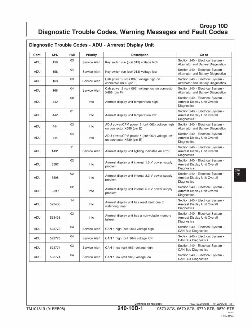
Diagnostic Trouble Codes - ADU - Armrest Display Unit
Cont. SPN FMI Priority Description Go to
03 Section 240 - Electrical System -ADU 158 Service Alert Key switch run (cc# 013) voltage high
Alternator and Battery Diagnostics
04 Section 240 - Electrical System -ADU 158 Service Alert Key switch run (cc# 013) voltage low
Alternator and Battery Diagnostics
03 Cab power 2 (cc# 092) voltage high on Section 240 - Electrical System -ADU 168 Service Alert
connector X689 (pin F) Alternator and Battery Diagnostics
04 Cab power 2 (cc# 092) voltage low on connector Section 240 - Electrical System -ADU 168 Service Alert
X689 (pin F) Alternator and Battery Diagnostics
00 Section 240 - Electrical System -ADU 442 Info Armrest display unit temperature high Armrest Display Unit Overall
Diagnostics
01 Section 240 - Electrical System -ADU 442 Info Armrest display unit temperature low Armrest Display Unit Overall
Diagnostics
03 ADU power/CPM power 5 (cc# 062) voltage high Section 240 - Electrical System -ADU 444 Info
on connector X689 (pin E) Alternator and Battery Diagnostics
04 Section 240 - Electrical System -ADU power/CPM power 5 (cc# 062) voltage low
ADU 444 Info Armrest Display Unit Overallon connector X689 (pin E)
Diagnostics
11 Section 240 - Electrical System -ADU 1491 Service Alert Armrest display unit lighting indicates an error. Armrest Display Unit Overall
Diagnostics
02 Section 240 - Electrical System -Armrest display unit internal 1.5 V power supply
ADU 3587 Info Armrest Display Unit Overallproblem
Diagnostics
02 Section 240 - Electrical System -Armrest display unit internal 3.3 V power supply
ADU 3598 Info Armrest Display Unit Overallproblem
Diagnostics
02 Section 240 - Electrical System -Armrest display unit internal 5.0 V power supply
ADU 3599 Info Armrest Display Unit Overallproblem
Diagnostics
14 Section 240 - Electrical System -Armrest display unit has reset itself due to
ADU 523436 Info Armrest Display Unit Overallwatchdog timer.
Diagnostics
02 Section 240 - Electrical System -Armrest display unit has a non-volatile memory
ADU 523438 Info Armrest Display Unit Overallfailure.
Diagnostics
03 Section 240 - Electrical System -ADU 523773 Service Alert CAN 1 high (cc# 964) voltage high
CAN Bus Diagnostics
04 Section 240 - Electrical System -ADU 523773 Service Alert CAN 1 high (cc# 964) voltage low
CAN Bus Diagnostics
03 Section 240 - Electrical System -ADU 523774 Service Alert CAN 1 low (cc# 965) voltage high
CAN Bus Diagnostics
04 Section 240 - Electrical System -ADU 523774 Service Alert CAN 1 low (cc# 965) voltage low
CAN Bus Diagnostics
TM101819 (01FEB08) 240-10D-1 9570 STS, 9670 STS, 9770 STS, 9870 STS121507
PN=1249
Continued on next page
Diagnostic Trouble Codes, Warning Messages and Fault Codes
24010D
2
HE97192,0001B18 –19–02AUG07–2/2
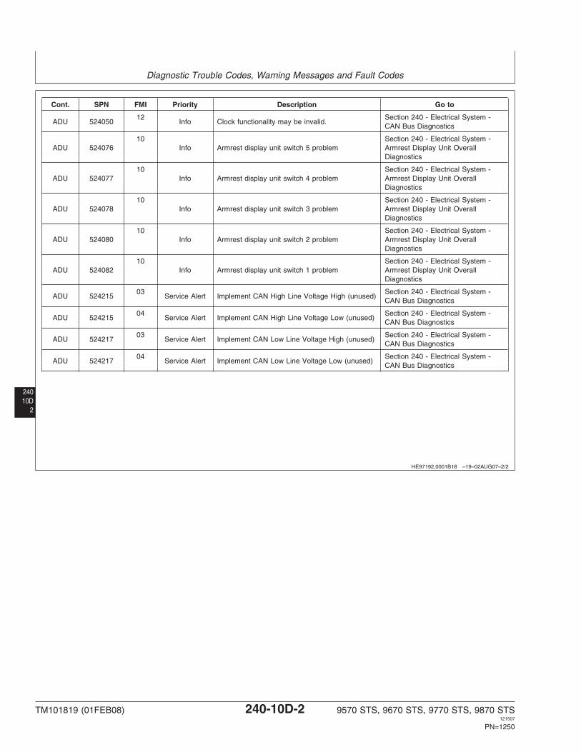
Cont. SPN FMI Priority Description Go to
12 Section 240 - Electrical System -ADU 524050 Info Clock functionality may be invalid.
CAN Bus Diagnostics
10 Section 240 - Electrical System -ADU 524076 Info Armrest display unit switch 5 problem Armrest Display Unit Overall
Diagnostics
10 Section 240 - Electrical System -ADU 524077 Info Armrest display unit switch 4 problem Armrest Display Unit Overall
Diagnostics
10 Section 240 - Electrical System -ADU 524078 Info Armrest display unit switch 3 problem Armrest Display Unit Overall
Diagnostics
10 Section 240 - Electrical System -ADU 524080 Info Armrest display unit switch 2 problem Armrest Display Unit Overall
Diagnostics
10 Section 240 - Electrical System -ADU 524082 Info Armrest display unit switch 1 problem Armrest Display Unit Overall
Diagnostics
03 Section 240 - Electrical System -ADU 524215 Service Alert Implement CAN High Line Voltage High (unused)
CAN Bus Diagnostics
04 Section 240 - Electrical System -ADU 524215 Service Alert Implement CAN High Line Voltage Low (unused)
CAN Bus Diagnostics
03 Section 240 - Electrical System -ADU 524217 Service Alert Implement CAN Low Line Voltage High (unused)
CAN Bus Diagnostics
04 Section 240 - Electrical System -ADU 524217 Service Alert Implement CAN Low Line Voltage Low (unused)
CAN Bus Diagnostics
TM101819 (01FEB08) 240-10D-2 9570 STS, 9670 STS, 9770 STS, 9870 STS121507
PN=1250
Diagnostic Trouble Codes, Warning Messages and Fault Codes
24010D3
HE97192,0001B12 –19–07SEP07–1/10
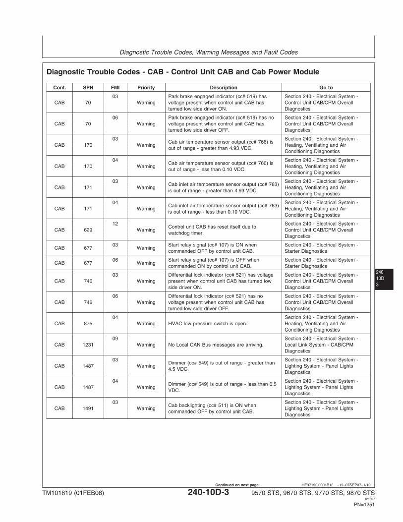
Diagnostic Trouble Codes - CAB - Control Unit CAB and Cab Power Module
Cont. SPN FMI Priority Description Go to
03 Park brake engaged indicator (cc# 519) has Section 240 - Electrical System -CAB 70 Warning voltage present when control unit CAB has Control Unit CAB/CPM Overall
turned low side driver ON. Diagnostics
06 Park brake engaged indicator (cc# 519) has no Section 240 - Electrical System -CAB 70 Warning voltage present when control unit CAB has Control Unit CAB/CPM Overall
turned low side driver OFF. Diagnostics
03 Section 240 - Electrical System -Cab air temperature sensor output (cc# 766) is
CAB 170 Warning Heating, Ventilating and Airout of range - greater than 4.93 VDC.
Conditioning Diagnostics
04 Section 240 - Electrical System -Cab air temperature sensor output (cc# 766) is
CAB 170 Warning Heating, Ventilating and Airout of range - less than 0.10 VDC.
Conditioning Diagnostics
03 Section 240 - Electrical System -Cab inlet air temperature sensor output (cc# 763)
CAB 171 Warning Heating, Ventilating and Airis out of range - greater than 4.93 VDC.
Conditioning Diagnostics
04 Section 240 - Electrical System -Cab inlet air temperature sensor output (cc# 763)
CAB 171 Warning Heating, Ventilating and Airis out of range - less than 0.10 VDC.
Conditioning Diagnostics
12 Section 240 - Electrical System -Control unit CAB has reset itself due to
CAB 629 Warning Control Unit CAB/CPM Overallwatchdog timer.
Diagnostics
03 Start relay signal (cc# 107) is ON when Section 240 - Electrical System -CAB 677 Warning
commanded OFF by control unit CAB. Starter Diagnostics
06 Start relay signal (cc# 107) is OFF when Section 240 - Electrical System -CAB 677 Warning
commanded ON by control unit CAB. Starter Diagnostics
03 Differential lock indicator (cc# 521) has voltage Section 240 - Electrical System -CAB 746 Warning present when control unit CAB has turned low Control Unit CAB/CPM Overall
side driver ON. Diagnostics
06 Differential lock indicator (cc# 521) has no Section 240 - Electrical System -CAB 746 Warning voltage present when control unit CAB has Control Unit CAB/CPM Overall
turned low side driver OFF. Diagnostics
04 Section 240 - Electrical System -CAB 875 Warning HVAC low pressure switch is open. Heating, Ventilating and Air
Conditioning Diagnostics
09 Section 240 - Electrical System -CAB 1231 Warning No Local CAN Bus messages are arriving. Local Link System - CAB/CPM
Diagnostics
03 Section 240 - Electrical System -Dimmer (cc# 549) is out of range - greater than
CAB 1487 Warning Lighting System - Panel Lights4.5 VDC.
Diagnostics
04 Section 240 - Electrical System -Dimmer (cc# 549) is out of range - less than 0.5
CAB 1487 Warning Lighting System - Panel LightsVDC.
Diagnostics
03 Section 240 - Electrical System -Cab backlighting (cc# 511) is ON when
CAB 1491 Warning Lighting System - Panel Lightscommanded OFF by control unit CAB.
Diagnostics
TM101819 (01FEB08) 240-10D-3 9570 STS, 9670 STS, 9770 STS, 9870 STS121507
PN=1251
Continued on next page
Diagnostic Trouble Codes, Warning Messages and Fault Codes
24010D
4
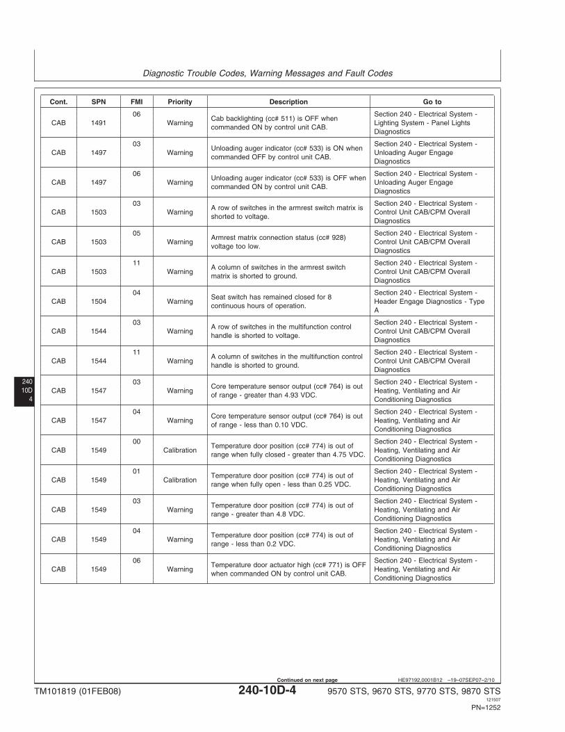
HE97192,0001B12 –19–07SEP07–2/10
Cont. SPN FMI Priority Description Go to
06 Section 240 - Electrical System -Cab backlighting (cc# 511) is OFF when
CAB 1491 Warning Lighting System - Panel Lightscommanded ON by control unit CAB.
Diagnostics
03 Section 240 - Electrical System -Unloading auger indicator (cc# 533) is ON when
CAB 1497 Warning Unloading Auger Engagecommanded OFF by control unit CAB.
Diagnostics
06 Section 240 - Electrical System -Unloading auger indicator (cc# 533) is OFF when
CAB 1497 Warning Unloading Auger Engagecommanded ON by control unit CAB.
Diagnostics
03 Section 240 - Electrical System -A row of switches in the armrest switch matrix is
CAB 1503 Warning Control Unit CAB/CPM Overallshorted to voltage.
Diagnostics
05 Section 240 - Electrical System -Armrest matrix connection status (cc# 928)
CAB 1503 Warning Control Unit CAB/CPM Overallvoltage too low.
Diagnostics
11 Section 240 - Electrical System -A column of switches in the armrest switch
CAB 1503 Warning Control Unit CAB/CPM Overallmatrix is shorted to ground.
Diagnostics
04 Section 240 - Electrical System -Seat switch has remained closed for 8
CAB 1504 Warning Header Engage Diagnostics - Typecontinuous hours of operation.
A
03 Section 240 - Electrical System -A row of switches in the multifunction control
CAB 1544 Warning Control Unit CAB/CPM Overallhandle is shorted to voltage.
Diagnostics
11 Section 240 - Electrical System -A column of switches in the multifunction control
CAB 1544 Warning Control Unit CAB/CPM Overallhandle is shorted to ground.
Diagnostics
03 Section 240 - Electrical System -Core temperature sensor output (cc# 764) is out
CAB 1547 Warning Heating, Ventilating and Airof range - greater than 4.93 VDC.
Conditioning Diagnostics
04 Section 240 - Electrical System -Core temperature sensor output (cc# 764) is out
CAB 1547 Warning Heating, Ventilating and Airof range - less than 0.10 VDC.
Conditioning Diagnostics
00 Section 240 - Electrical System -Temperature door position (cc# 774) is out of
CAB 1549 Calibration Heating, Ventilating and Airrange when fully closed - greater than 4.75 VDC.
Conditioning Diagnostics
01 Section 240 - Electrical System -Temperature door position (cc# 774) is out of
CAB 1549 Calibration Heating, Ventilating and Airrange when fully open - less than 0.25 VDC.
Conditioning Diagnostics
03 Section 240 - Electrical System -Temperature door position (cc# 774) is out of
CAB 1549 Warning Heating, Ventilating and Airrange - greater than 4.8 VDC.
Conditioning Diagnostics
04 Section 240 - Electrical System -Temperature door position (cc# 774) is out of
CAB 1549 Warning Heating, Ventilating and Airrange - less than 0.2 VDC.
Conditioning Diagnostics
06 Section 240 - Electrical System -Temperature door actuator high (cc# 771) is OFF
CAB 1549 Warning Heating, Ventilating and Airwhen commanded ON by control unit CAB.
Conditioning Diagnostics
TM101819 (01FEB08) 240-10D-4 9570 STS, 9670 STS, 9770 STS, 9870 STS121507
PN=1252
Continued on next page
Diagnostic Trouble Codes, Warning Messages and Fault Codes
24010D5
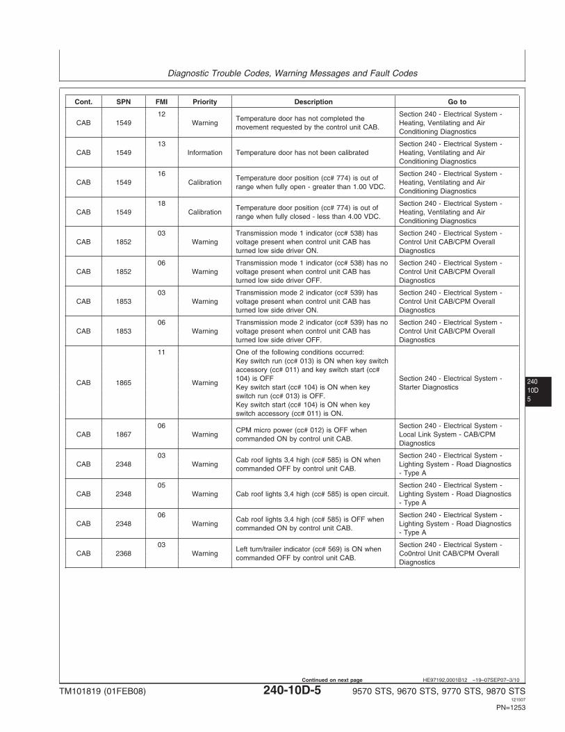
HE97192,0001B12 –19–07SEP07–3/10
Cont. SPN FMI Priority Description Go to
12 Section 240 - Electrical System -Temperature door has not completed the
CAB 1549 Warning Heating, Ventilating and Airmovement requested by the control unit CAB.
Conditioning Diagnostics
13 Section 240 - Electrical System -CAB 1549 Information Temperature door has not been calibrated Heating, Ventilating and Air
Conditioning Diagnostics
16 Section 240 - Electrical System -Temperature door position (cc# 774) is out of
CAB 1549 Calibration Heating, Ventilating and Airrange when fully open - greater than 1.00 VDC.
Conditioning Diagnostics
18 Section 240 - Electrical System -Temperature door position (cc# 774) is out of
CAB 1549 Calibration Heating, Ventilating and Airrange when fully closed - less than 4.00 VDC.
Conditioning Diagnostics
03 Transmission mode 1 indicator (cc# 538) has Section 240 - Electrical System -CAB 1852 Warning voltage present when control unit CAB has Control Unit CAB/CPM Overall
turned low side driver ON. Diagnostics
06 Transmission mode 1 indicator (cc# 538) has no Section 240 - Electrical System -CAB 1852 Warning voltage present when control unit CAB has Control Unit CAB/CPM Overall
turned low side driver OFF. Diagnostics
03 Transmission mode 2 indicator (cc# 539) has Section 240 - Electrical System -CAB 1853 Warning voltage present when control unit CAB has Control Unit CAB/CPM Overall
turned low side driver ON. Diagnostics
06 Transmission mode 2 indicator (cc# 539) has no Section 240 - Electrical System -CAB 1853 Warning voltage present when control unit CAB has Control Unit CAB/CPM Overall
turned low side driver OFF. Diagnostics
11 One of the following conditions occurred:Key switch run (cc# 013) is ON when key switchaccessory (cc# 011) and key switch start (cc#104) is OFF Section 240 - Electrical System -
CAB 1865 WarningKey switch start (cc# 104) is ON when key Starter Diagnosticsswitch run (cc# 013) is OFF.Key switch start (cc# 104) is ON when keyswitch accessory (cc# 011) is ON.
06 Section 240 - Electrical System -CPM micro power (cc# 012) is OFF when
CAB 1867 Warning Local Link System - CAB/CPMcommanded ON by control unit CAB.
Diagnostics
03 Section 240 - Electrical System -Cab roof lights 3,4 high (cc# 585) is ON when
CAB 2348 Warning Lighting System - Road Diagnosticscommanded OFF by control unit CAB.
- Type A
05 Section 240 - Electrical System -CAB 2348 Warning Cab roof lights 3,4 high (cc# 585) is open circuit. Lighting System - Road Diagnostics
- Type A
06 Section 240 - Electrical System -Cab roof lights 3,4 high (cc# 585) is OFF when
CAB 2348 Warning Lighting System - Road Diagnosticscommanded ON by control unit CAB.
- Type A
03 Section 240 - Electrical System -Left turn/trailer indicator (cc# 569) is ON when
CAB 2368 Warning Co0ntrol Unit CAB/CPM Overallcommanded OFF by control unit CAB.
Diagnostics
TM101819 (01FEB08) 240-10D-5 9570 STS, 9670 STS, 9770 STS, 9870 STS121507
PN=1253
Continued on next page
Diagnostic Trouble Codes, Warning Messages and Fault Codes
24010D
6
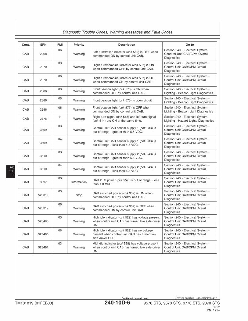
HE97192,0001B12 –19–07SEP07–4/10
Cont. SPN FMI Priority Description Go to
06 Section 240 - Electrical System -Left turn/trailer indicator (cc# 569) is OFF when
CAB 2368 Warning Co0ntrol Unit CAB/CPM Overallcommanded ON by control unit CAB.
Diagnostics
03 Section 240 - Electrical System -Right turn/combine indicator (cc# 597) is ON
CAB 2370 Warning Control Unit CAB/CPM Overallwhen commanded OFF by control unit CAB.
Diagnostics
06 Section 240 - Electrical System -Right turn/combine indicator (cc# 597) is OFF
CAB 2370 Warning Control Unit CAB/CPM Overallwhen commanded ON by control unit CAB.
Diagnostics
03 Front beacon light (cc# 573) is ON when Section 240 - Electrical System -CAB 2386 Warning
commanded OFF by control unit CAB. Lighting - Beacon Light Diagnostics
05 Section 240 - Electrical System -CAB 2386 Warning Front beacon light (cc# 573) is open circuit.
Lighting - Beacon Light Diagnostics
06 Front beacon light (cc# 573) is OFF when Section 240 - Electrical System -CAB 2386 Warning
commanded ON by control unit CAB. Lighting - Beacon Light Diagnostics
11 Right turn signal (cc# 513) and left turn signal Section 240 - Electrical System -CAB 2876 Warning
(cc# 514) are ON at the same time. Lighting - Hazard Lights Diagnostics
03 Section 240 - Electrical System -Control unit CAB sensor supply 1 (cc# 233) is
CAB 3509 Warning Control Unit CAB/CPM Overallout of range - greater than 5.5 VDC.
Diagnostics
04 Section 240 - Electrical System -Control unit CAB sensor supply 1 (cc# 233) is
CAB 3509 Warning Control Unit CAB/CPM Overallout of range - less than 4.5 VDC.
Diagnostics
03 Section 240 - Electrical System -Control unit CAB sensor supply 2 (cc# 243) is
CAB 3510 Warning Control Unit CAB/CPM Overallout of range - greater than 5.5 VDC.
Diagnostics
04 Section 240 - Electrical System -Control unit CAB sensor supply 2 (cc# 243) is
CAB 3510 Warning Control Unit CAB/CPM Overallout of range - less than 4.5 VDC.
Diagnostics
06 Section 240 - Electrical System -CAB PTC power (cc# 552) is out of range - less
CAB 3597 Information Control Unit CAB/CPM Overallthan 4.0 VDC.
Diagnostics
03 Section 240 - Electrical System -CAB switched power (cc# 932) is ON when
CAB 523319 Stop Control Unit CAB/CPM Overallcommanded OFF by control unit CAB.
Diagnostics
06 Section 240 - Electrical System -CAB switched power (cc# 932) is OFF when
CAB 523319 Warning Control Unit CAB/CPM Overallcommanded ON by control unit CAB.
Diagnostics
03 High idle indicator (cc# 529) has voltage present Section 240 - Electrical System -CAB 523490 Warning when control unit CAB has turned low side driver Control Unit CAB/CPM Overall
ON. Diagnostics
06 High idle indicator (cc# 529) has no voltage Section 240 - Electrical System -CAB 523490 Warning present when control unit CAB has turned low Control Unit CAB/CPM Overall
side driver OFF. Diagnostics
03 Mid idle indicator (cc# 528) has voltage present Section 240 - Electrical System -CAB 523491 Warning when control unit CAB has turned low side driver Control Unit CAB/CPM Overall
ON. Diagnostics
TM101819 (01FEB08) 240-10D-6 9570 STS, 9670 STS, 9770 STS, 9870 STS121507
PN=1254
Continued on next page
Diagnostic Trouble Codes, Warning Messages and Fault Codes
24010D7
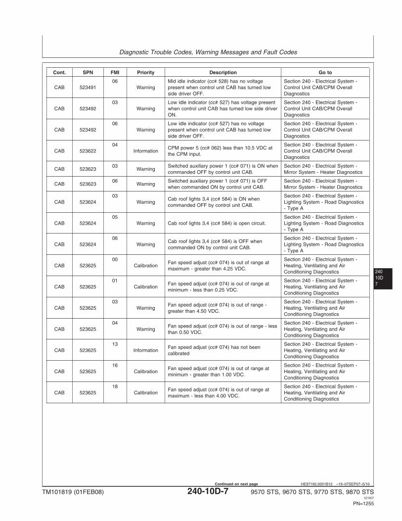
HE97192,0001B12 –19–07SEP07–5/10
Cont. SPN FMI Priority Description Go to
06 Mid idle indicator (cc# 528) has no voltage Section 240 - Electrical System -CAB 523491 Warning present when control unit CAB has turned low Control Unit CAB/CPM Overall
side driver OFF. Diagnostics
03 Low idle indicator (cc# 527) has voltage present Section 240 - Electrical System -CAB 523492 Warning when control unit CAB has turned low side driver Control Unit CAB/CPM Overall
ON. Diagnostics
06 Low idle indicator (cc# 527) has no voltage Section 240 - Electrical System -CAB 523492 Warning present when control unit CAB has turned low Control Unit CAB/CPM Overall
side driver OFF. Diagnostics
04 Section 240 - Electrical System -CPM power 5 (cc# 062) less than 10.5 VDC at
CAB 523622 Information Control Unit CAB/CPM Overallthe CPM input.
Diagnostics
03 Switched auxiliary power 1 (cc# 071) is ON when Section 240 - Electrical System -CAB 523623 Warning
commanded OFF by control unit CAB. Mirror System - Heater Diagnostics
06 Switched auxiliary power 1 (cc# 071) is OFF Section 240 - Electrical System -CAB 523623 Warning
when commanded ON by control unit CAB. Mirror System - Heater Diagnostics
03 Section 240 - Electrical System -Cab roof lights 3,4 (cc# 584) is ON when
CAB 523624 Warning Lighting System - Road Diagnosticscommanded OFF by control unit CAB.
- Type A
05 Section 240 - Electrical System -CAB 523624 Warning Cab roof lights 3,4 (cc# 584) is open circuit. Lighting System - Road Diagnostics
- Type A
06 Section 240 - Electrical System -Cab roof lights 3,4 (cc# 584) is OFF when
CAB 523624 Warning Lighting System - Road Diagnosticscommanded ON by control unit CAB.
- Type A
00 Section 240 - Electrical System -Fan speed adjust (cc# 074) is out of range at
CAB 523625 Calibration Heating, Ventilating and Airmaximum - greater than 4.25 VDC.
Conditioning Diagnostics
01 Section 240 - Electrical System -Fan speed adjust (cc# 074) is out of range at
CAB 523625 Calibration Heating, Ventilating and Airminimum - less than 0.25 VDC.
Conditioning Diagnostics
03 Section 240 - Electrical System -Fan speed adjust (cc# 074) is out of range -
CAB 523625 Warning Heating, Ventilating and Airgreater than 4.50 VDC.
Conditioning Diagnostics
04 Section 240 - Electrical System -Fan speed adjust (cc# 074) is out of range - less
CAB 523625 Warning Heating, Ventilating and Airthan 0.50 VDC.
Conditioning Diagnostics
13 Section 240 - Electrical System -Fan speed adjust (cc# 074) has not been
CAB 523625 Information Heating, Ventilating and Aircalibrated
Conditioning Diagnostics
16 Section 240 - Electrical System -Fan speed adjust (cc# 074) is out of range at
CAB 523625 Calibration Heating, Ventilating and Airminimum - greater than 1.00 VDC.
Conditioning Diagnostics
18 Section 240 - Electrical System -Fan speed adjust (cc# 074) is out of range at
CAB 523625 Calibration Heating, Ventilating and Airmaximum - less than 4.00 VDC.
Conditioning Diagnostics
TM101819 (01FEB08) 240-10D-7 9570 STS, 9670 STS, 9770 STS, 9870 STS121507
PN=1255
Continued on next page
Diagnostic Trouble Codes, Warning Messages and Fault Codes
24010D
8
HE97192,0001B12 –19–07SEP07–6/10
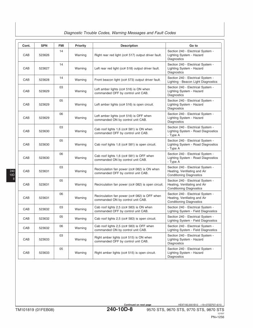
Cont. SPN FMI Priority Description Go to
14 Section 240 - Electrical System -CAB 523626 Warning Right rear red light (cc# 517) output driver fault. Lighting System - Hazard
Diagnostics
14 Section 240 - Electrical System -CAB 523627 Warning Left rear red light (cc# 518) output driver fault. Lighting System - Hazard
Diagnostics
14 Section 240 - Electrical System -CAB 523628 Warning Front beacon light (cc# 573) output driver fault.
Lighting - Beacon Light Diagnostics
03 Section 240 - Electrical System -Left amber lights (cc# 516) is ON when
CAB 523629 Warning Lighting System - Hazardcommanded OFF by control unit CAB.
Diagnostics
05 Section 240 - Electrical System -CAB 523629 Warning Left amber lights (cc# 516) is open circuit. Lighting System - Hazard
Diagnostics
06 Section 240 - Electrical System -Left amber lights (cc# 516) is OFF when
CAB 523629 Warning Lighting System - Hazardcommanded ON by control unit CAB.
Diagnostics
03 Section 240 - Electrical System -Cab roof lights 1,6 (cc# 581) is ON when
CAB 523630 Warning Lighting System - Road Diagnosticscommanded OFF by control unit CAB.
- Type A
05 Section 240 - Electrical System -CAB 523630 Warning Cab roof lights 1,6 (cc# 581) is open circuit. Lighting System - Road Diagnostics
- Type A
06 Section 240 - Electrical System -Cab roof lights 1,6 (cc# 581) is OFF when
CAB 523630 Warning Lighting System - Road Diagnosticscommanded ON by control unit CAB.
- Type A
03 Section 240 - Electrical System -Recirculation fan power (cc# 082) is ON when
CAB 523631 Warning Heating, Ventilating and Aircommanded OFF by control unit CAB.
Conditioning Diagnostics
05 Section 240 - Electrical System -CAB 523631 Warning Recirculation fan power (cc# 082) is open circuit. Heating, Ventilating and Air
Conditioning Diagnostics
06 Section 240 - Electrical System -Recirculation fan power (cc# 082) is OFF when
CAB 523631 Warning Heating, Ventilating and Aircommanded ON by control unit CAB.
Conditioning Diagnostics
03 Cab roof lights 2,5 (cc# 583) is ON when Section 240 - Electrical System -CAB 523632 Warning
commanded OFF by control unit CAB. Lighting System - Field Diagnostics
05 Section 240 - Electrical System -CAB 523632 Warning Cab roof lights 2,5 (cc# 583) is open circuit.
Lighting System - Field Diagnostics
06 Cab roof lights 2,5 (cc# 583) is OFF when Section 240 - Electrical System -CAB 523632 Warning
commanded ON by control unit CAB. Lighting System - Field Diagnostics
03 Section 240 - Electrical System -Right amber lights (cc# 515) is ON when
CAB 523633 Warning Lighting System - Hazardcommanded OFF by control unit CAB.
Diagnostics
05 Section 240 - Electrical System -CAB 523633 Warning Right amber lights (cc# 515) is open circuit. Lighting System - Hazard
Diagnostics
TM101819 (01FEB08) 240-10D-8 9570 STS, 9670 STS, 9770 STS, 9870 STS121507
PN=1256
Continued on next page
Diagnostic Trouble Codes, Warning Messages and Fault Codes
24010D9
HE97192,0001B12 –19–07SEP07–7/10
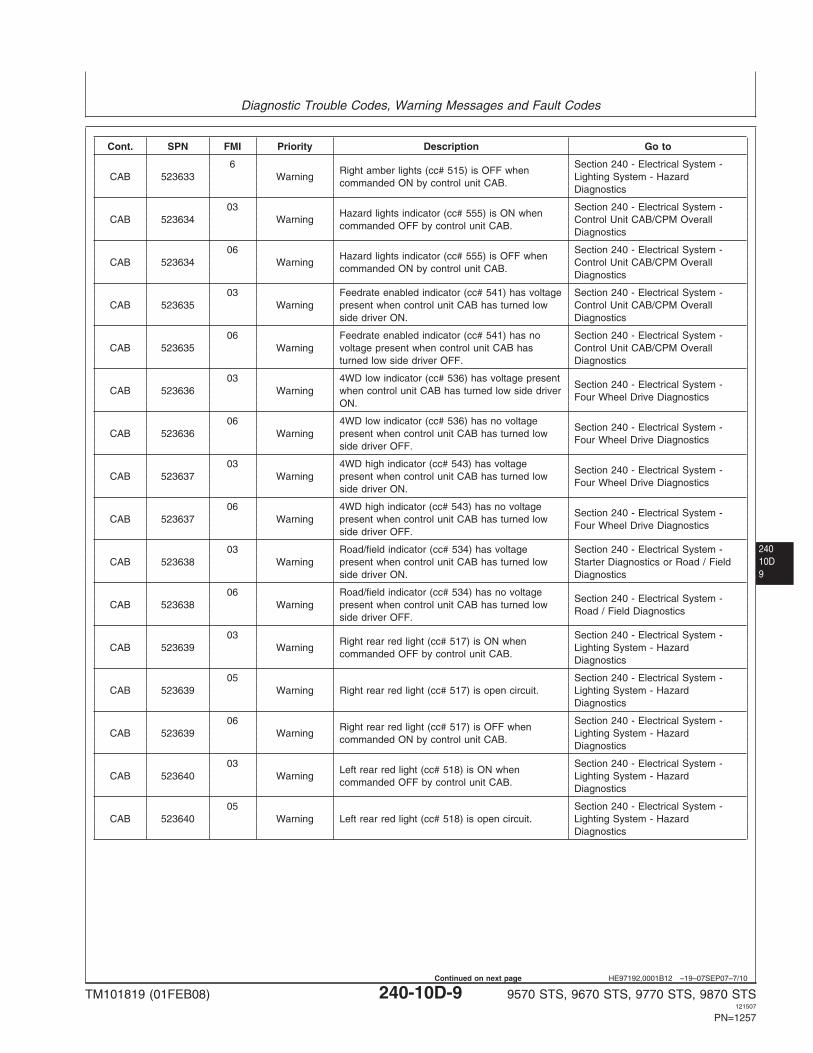
Cont. SPN FMI Priority Description Go to
6 Section 240 - Electrical System -Right amber lights (cc# 515) is OFF when
CAB 523633 Warning Lighting System - Hazardcommanded ON by control unit CAB.
Diagnostics
03 Section 240 - Electrical System -Hazard lights indicator (cc# 555) is ON when
CAB 523634 Warning Control Unit CAB/CPM Overallcommanded OFF by control unit CAB.
Diagnostics
06 Section 240 - Electrical System -Hazard lights indicator (cc# 555) is OFF when
CAB 523634 Warning Control Unit CAB/CPM Overallcommanded ON by control unit CAB.
Diagnostics
03 Feedrate enabled indicator (cc# 541) has voltage Section 240 - Electrical System -CAB 523635 Warning present when control unit CAB has turned low Control Unit CAB/CPM Overall
side driver ON. Diagnostics
06 Feedrate enabled indicator (cc# 541) has no Section 240 - Electrical System -CAB 523635 Warning voltage present when control unit CAB has Control Unit CAB/CPM Overall
turned low side driver OFF. Diagnostics
03 4WD low indicator (cc# 536) has voltage presentSection 240 - Electrical System -
CAB 523636 Warning when control unit CAB has turned low side driverFour Wheel Drive Diagnostics
ON.
06 4WD low indicator (cc# 536) has no voltageSection 240 - Electrical System -
CAB 523636 Warning present when control unit CAB has turned lowFour Wheel Drive Diagnostics
side driver OFF.
03 4WD high indicator (cc# 543) has voltageSection 240 - Electrical System -
CAB 523637 Warning present when control unit CAB has turned lowFour Wheel Drive Diagnostics
side driver ON.
06 4WD high indicator (cc# 543) has no voltageSection 240 - Electrical System -
CAB 523637 Warning present when control unit CAB has turned lowFour Wheel Drive Diagnostics
side driver OFF.
03 Road/field indicator (cc# 534) has voltage Section 240 - Electrical System -CAB 523638 Warning present when control unit CAB has turned low Starter Diagnostics or Road / Field
side driver ON. Diagnostics
06 Road/field indicator (cc# 534) has no voltageSection 240 - Electrical System -
CAB 523638 Warning present when control unit CAB has turned lowRoad / Field Diagnostics
side driver OFF.
03 Section 240 - Electrical System -Right rear red light (cc# 517) is ON when
CAB 523639 Warning Lighting System - Hazardcommanded OFF by control unit CAB.
Diagnostics
05 Section 240 - Electrical System -CAB 523639 Warning Right rear red light (cc# 517) is open circuit. Lighting System - Hazard
Diagnostics
06 Section 240 - Electrical System -Right rear red light (cc# 517) is OFF when
CAB 523639 Warning Lighting System - Hazardcommanded ON by control unit CAB.
Diagnostics
03 Section 240 - Electrical System -Left rear red light (cc# 518) is ON when
CAB 523640 Warning Lighting System - Hazardcommanded OFF by control unit CAB.
Diagnostics
05 Section 240 - Electrical System -CAB 523640 Warning Left rear red light (cc# 518) is open circuit. Lighting System - Hazard
Diagnostics
TM101819 (01FEB08) 240-10D-9 9570 STS, 9670 STS, 9770 STS, 9870 STS121507
PN=1257
Continued on next page
Diagnostic Trouble Codes, Warning Messages and Fault Codes
24010D
10
HE97192,0001B12 –19–07SEP07–8/10
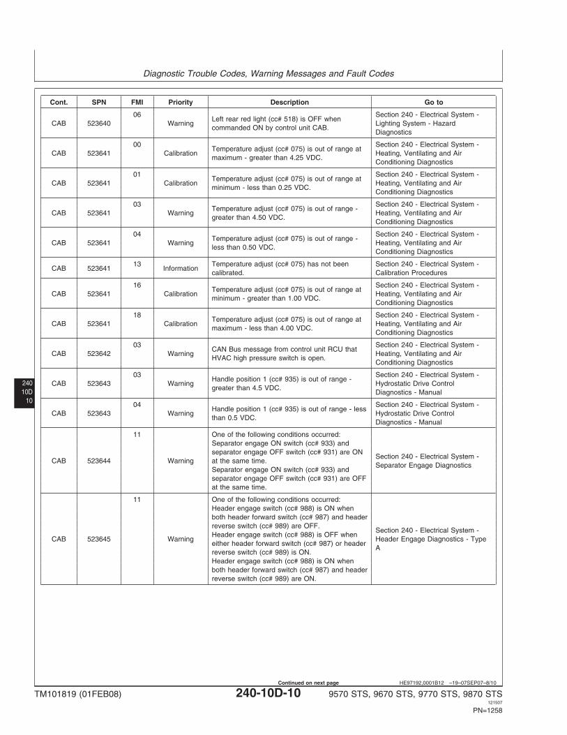
Cont. SPN FMI Priority Description Go to
06 Section 240 - Electrical System -Left rear red light (cc# 518) is OFF when
CAB 523640 Warning Lighting System - Hazardcommanded ON by control unit CAB.
Diagnostics
00 Section 240 - Electrical System -Temperature adjust (cc# 075) is out of range at
CAB 523641 Calibration Heating, Ventilating and Airmaximum - greater than 4.25 VDC.
Conditioning Diagnostics
01 Section 240 - Electrical System -Temperature adjust (cc# 075) is out of range at
CAB 523641 Calibration Heating, Ventilating and Airminimum - less than 0.25 VDC.
Conditioning Diagnostics
03 Section 240 - Electrical System -Temperature adjust (cc# 075) is out of range -
CAB 523641 Warning Heating, Ventilating and Airgreater than 4.50 VDC.
Conditioning Diagnostics
04 Section 240 - Electrical System -Temperature adjust (cc# 075) is out of range -
CAB 523641 Warning Heating, Ventilating and Airless than 0.50 VDC.
Conditioning Diagnostics
13 Temperature adjust (cc# 075) has not been Section 240 - Electrical System -CAB 523641 Information
calibrated. Calibration Procedures
16 Section 240 - Electrical System -Temperature adjust (cc# 075) is out of range at
CAB 523641 Calibration Heating, Ventilating and Airminimum - greater than 1.00 VDC.
Conditioning Diagnostics
18 Section 240 - Electrical System -Temperature adjust (cc# 075) is out of range at
CAB 523641 Calibration Heating, Ventilating and Airmaximum - less than 4.00 VDC.
Conditioning Diagnostics
03 Section 240 - Electrical System -CAN Bus message from control unit RCU that
CAB 523642 Warning Heating, Ventilating and AirHVAC high pressure switch is open.
Conditioning Diagnostics
03 Section 240 - Electrical System -Handle position 1 (cc# 935) is out of range -
CAB 523643 Warning Hydrostatic Drive Controlgreater than 4.5 VDC.
Diagnostics - Manual
04 Section 240 - Electrical System -Handle position 1 (cc# 935) is out of range - less
CAB 523643 Warning Hydrostatic Drive Controlthan 0.5 VDC.
Diagnostics - Manual
11 One of the following conditions occurred:Separator engage ON switch (cc# 933) andseparator engage OFF switch (cc# 931) are ON
Section 240 - Electrical System -CAB 523644 Warning at the same time.
Separator Engage DiagnosticsSeparator engage ON switch (cc# 933) andseparator engage OFF switch (cc# 931) are OFFat the same time.
11 One of the following conditions occurred:Header engage switch (cc# 988) is ON whenboth header forward switch (cc# 987) and headerreverse switch (cc# 989) are OFF.
Section 240 - Electrical System -Header engage switch (cc# 988) is OFF when
CAB 523645 Warning Header Engage Diagnostics - Typeeither header forward switch (cc# 987) or header
Areverse switch (cc# 989) is ON.Header engage switch (cc# 988) is ON whenboth header forward switch (cc# 987) and headerreverse switch (cc# 989) are ON.
TM101819 (01FEB08) 240-10D-10 9570 STS, 9670 STS, 9770 STS, 9870 STS121507
PN=1258
Continued on next page
Diagnostic Trouble Codes, Warning Messages and Fault Codes
24010D11
HE97192,0001B12 –19–07SEP07–9/10
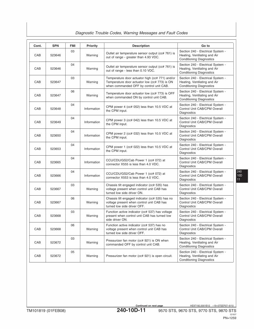
Cont. SPN FMI Priority Description Go to
03 Section 240 - Electrical System -Outlet air temperature sensor output (cc# 761) is
CAB 523646 Warning Heating, Ventilating and Airout of range - greater than 4.93 VDC.
Conditioning Diagnostics
04 Section 240 - Electrical System -Outlet air temperature sensor output (cc# 761) is
CAB 523646 Warning Heating, Ventilating and Airout of range - less than 0.10 VDC.
Conditioning Diagnostics
03 Temperature door actuator high (cc# 771) and/or Section 240 - Electrical System -CAB 523647 Warning Temperature door actuator low (cc# 773) is ON Heating, Ventilating and Air
when commanded OFF by control unit CAB. Conditioning Diagnostics
06 Section 240 - Electrical System -Temperature door actuator low (cc# 773) is OFF
CAB 523647 Warning Heating, Ventilating and Airwhen commanded ON by control unit CAB.
Conditioning Diagnostics
04 Section 240 - Electrical System -CPM power 4 (cc# 052) less than 10.5 VDC at
CAB 523648 Information Control Unit CAB/CPM Overallthe CPM input.
Diagnostics
04 Section 240 - Electrical System -CPM power 3 (cc# 042) less than 10.5 VDC at
CAB 523649 Information Control Unit CAB/CPM Overallthe CPM input.
Diagnostics
04 Section 240 - Electrical System -CPM power 2 (cc# 032) less than 10.5 VDC at
CAB 523650 Information Control Unit CAB/CPM Overallthe CPM input.
Diagnostics
04 Section 240 - Electrical System -CPM power 1 (cc# 022) less than 10.5 VDC at
CAB 523653 Information Control Unit CAB/CPM Overallthe CPM input.
Diagnostics
04 Section 240 - Electrical System -CCU/CDU/GS2/Cab Power 1 (cc# 072) at
CAB 523665 Information Control Unit CAB/CPM Overallconnector X555 is less than 4.0 VDC.
Diagnostics
04 Section 240 - Electrical System -CCU/CDU/GS2/Cab Power 1 (cc# 072) at
CAB 523666 Information Control Unit CAB/CPM Overallconnector X553 is less than 4.0 VDC.
Diagnostics
03 Chassis tilt engaged indicator (cc# 535) has Section 240 - Electrical System -CAB 523667 Warning voltage present when control unit CAB has Control Unit CAB/CPM Overall
turned low side driver ON. Diagnostics
06 Chassis tilt engaged indicator (cc# 535) has no Section 240 - Electrical System -CAB 523667 Warning voltage present when control unit CAB has Control Unit CAB/CPM Overall
turned low side driver OFF. Diagnostics
03 Function active indicator (cc# 537) has voltage Section 240 - Electrical System -CAB 523668 Warning present when control unit CAB has turned low Control Unit CAB/CPM Overall
side driver ON. Diagnostics
06 Function active indicator (cc# 537) has no Section 240 - Electrical System -CAB 523668 Warning voltage present when control unit CAB has Control Unit CAB/CPM Overall
turned low side driver OFF. Diagnostics
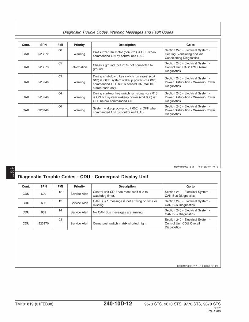
03 Section 240 - Electrical System -Pressurizer fan motor (cc# 921) is ON when
CAB 523672 Warning Heating, Ventilating and Aircommanded OFF by control unit CAB.
Conditioning Diagnostics
05 Section 240 - Electrical System -CAB 523672 Warning Pressurizer fan motor (cc# 921) is open circuit. Heating, Ventilating and Air
Conditioning Diagnostics
TM101819 (01FEB08) 240-10D-11 9570 STS, 9670 STS, 9770 STS, 9870 STS121507
PN=1259
Continued on next page
Diagnostic Trouble Codes, Warning Messages and Fault Codes
240 HE97192,0001B12 –19–07SEP07–10/10
Cont. SPN FMI Priority Description Go to
06 Section 240 - Electrical System -Pressurizer fan motor (cc# 921) is OFF when
CAB 523672 Warning Heating, Ventilating and Aircommanded ON by control unit CAB.
Conditioning Diagnostics
05 Section 240 - Electrical System -Chassis ground (cc# 010) not connected to
CAB 523673 Information Control Unit CAB/CPM Overallground.
Diagnostics
03 During shut-down, key switch run signal (cc#Section 240 - Electrical System -
013) is OFF, system wakeup power (cc# 006)CAB 523746 Warning Power Distribution - Wake-up Power
commanded OFF but is sensed ON. Will beDiagnostics
stored code only.
04 During start-up, key switch run signal (cc# 013) Section 240 - Electrical System -CAB 523746 Warning is ON but system wakeup power (cc# 006) is Power Distribution - Wake-up Power
OFF before commanded ON. Diagnostics
06 Section 240 - Electrical System -System wakeup power (cc# 006) is OFF when
CAB 523746 Warning Power Distribution - Wake-up Powercommanded ON by control unit CAB.
Diagnostics
10D12
HE97192,0001B17 –19–09JUL07–1/1
Diagnostic Trouble Codes - CDU - Cornerpost Display Unit
Cont. SPN FMI Priority Description Go to
12 Control unit CDU has reset itself due to Section 240 - Electrical System -CDU 629 Service Alert
watchdog timer. CAN Bus Diagnostics
12 CAN Bus 1 message is not arriving on time or Section 240 - Electrical System -CDU 639 Service Alert
missing. CAN Bus Diagnostics
14 Section 240 - Electrical System -CDU 639 Service Alert No CAN Bus messages are arriving.
CAN Bus Diagnostics
03 Section 240 - Electrical System -CDU 523370 Service Alert Cornerpost switch matrix shorted high Control Unit CDU Overall
Diagnostics
TM101819 (01FEB08) 240-10D-12 9570 STS, 9670 STS, 9770 STS, 9870 STS121507
PN=1260
Diagnostic Trouble Codes, Warning Messages and Fault Codes
24010D13
HE97192,0001B11 –19–02AUG07–1/8
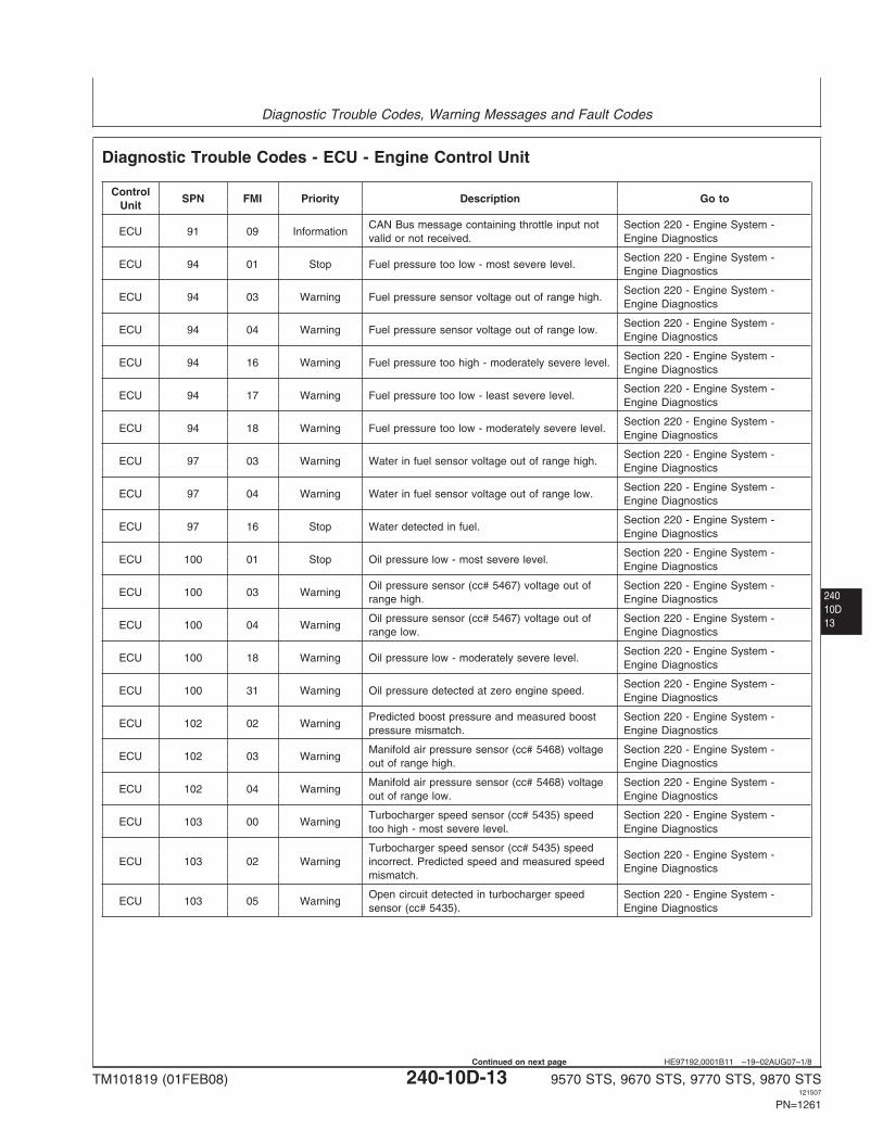
Diagnostic Trouble Codes - ECU - Engine Control Unit
ControlSPN FMI Priority Description Go to
Unit
CAN Bus message containing throttle input not Section 220 - Engine System -ECU 91 09 Information
valid or not received. Engine Diagnostics
Section 220 - Engine System -ECU 94 01 Stop Fuel pressure too low - most severe level.
Engine Diagnostics
Section 220 - Engine System -ECU 94 03 Warning Fuel pressure sensor voltage out of range high.
Engine Diagnostics
Section 220 - Engine System -ECU 94 04 Warning Fuel pressure sensor voltage out of range low.
Engine Diagnostics
Section 220 - Engine System -ECU 94 16 Warning Fuel pressure too high - moderately severe level.
Engine Diagnostics
Section 220 - Engine System -ECU 94 17 Warning Fuel pressure too low - least severe level.
Engine Diagnostics
Section 220 - Engine System -ECU 94 18 Warning Fuel pressure too low - moderately severe level.
Engine Diagnostics
Section 220 - Engine System -ECU 97 03 Warning Water in fuel sensor voltage out of range high.
Engine Diagnostics
Section 220 - Engine System -ECU 97 04 Warning Water in fuel sensor voltage out of range low.
Engine Diagnostics
Section 220 - Engine System -ECU 97 16 Stop Water detected in fuel.
Engine Diagnostics
Section 220 - Engine System -ECU 100 01 Stop Oil pressure low - most severe level.
Engine Diagnostics
Oil pressure sensor (cc# 5467) voltage out of Section 220 - Engine System -ECU 100 03 Warning
range high. Engine Diagnostics
Oil pressure sensor (cc# 5467) voltage out of Section 220 - Engine System -ECU 100 04 Warning
range low. Engine Diagnostics
Section 220 - Engine System -ECU 100 18 Warning Oil pressure low - moderately severe level.
Engine Diagnostics
Section 220 - Engine System -ECU 100 31 Warning Oil pressure detected at zero engine speed.
Engine Diagnostics
Predicted boost pressure and measured boost Section 220 - Engine System -ECU 102 02 Warning
pressure mismatch. Engine Diagnostics
Manifold air pressure sensor (cc# 5468) voltage Section 220 - Engine System -ECU 102 03 Warning
out of range high. Engine Diagnostics
Manifold air pressure sensor (cc# 5468) voltage Section 220 - Engine System -ECU 102 04 Warning
out of range low. Engine Diagnostics
Turbocharger speed sensor (cc# 5435) speed Section 220 - Engine System -ECU 103 00 Warning
too high - most severe level. Engine Diagnostics
Turbocharger speed sensor (cc# 5435) speedSection 220 - Engine System -
ECU 103 02 Warning incorrect. Predicted speed and measured speedEngine Diagnostics
mismatch.
Open circuit detected in turbocharger speed Section 220 - Engine System -ECU 103 05 Warning
sensor (cc# 5435). Engine Diagnostics
TM101819 (01FEB08) 240-10D-13 9570 STS, 9670 STS, 9770 STS, 9870 STS121507
PN=1261
Continued on next page
Diagnostic Trouble Codes, Warning Messages and Fault Codes
24010D
14
HE97192,0001B11 –19–02AUG07–2/8
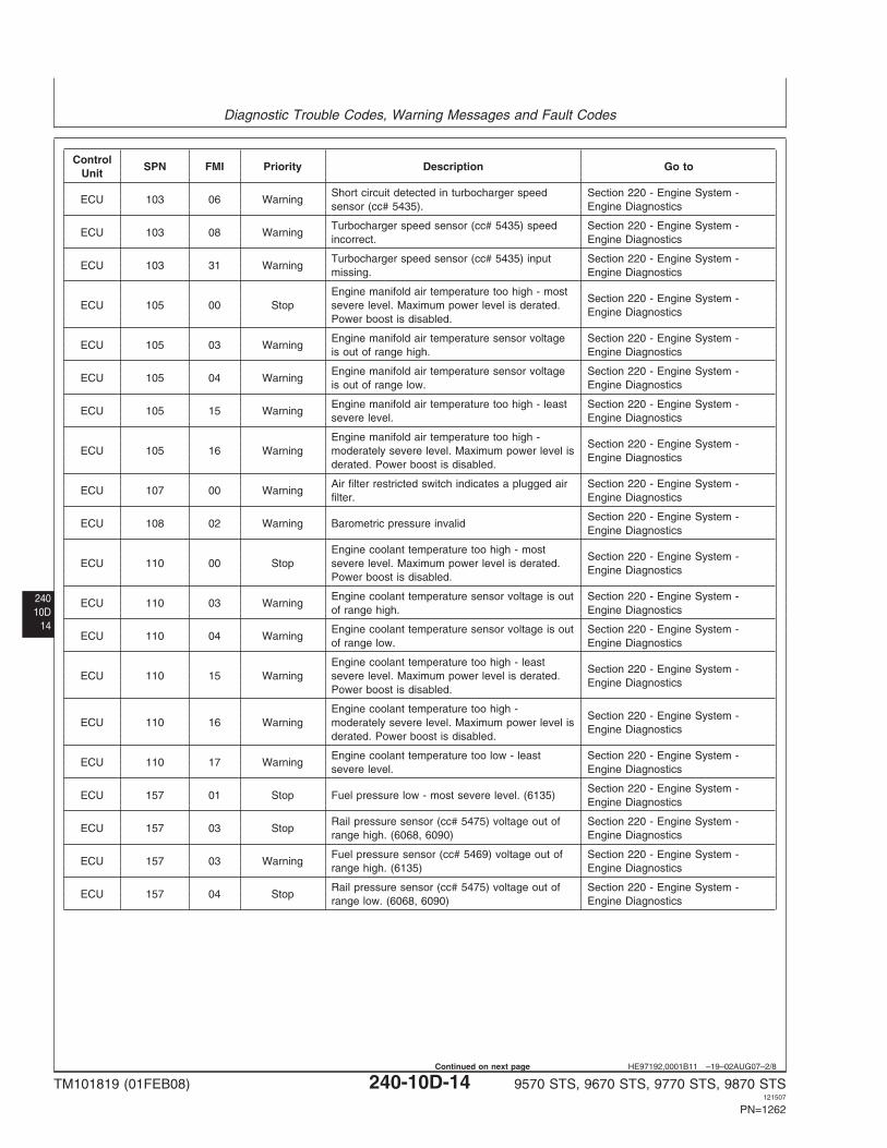
ControlSPN FMI Priority Description Go to
Unit
Short circuit detected in turbocharger speed Section 220 - Engine System -ECU 103 06 Warning
sensor (cc# 5435). Engine Diagnostics
Turbocharger speed sensor (cc# 5435) speed Section 220 - Engine System -ECU 103 08 Warning
incorrect. Engine Diagnostics
Turbocharger speed sensor (cc# 5435) input Section 220 - Engine System -ECU 103 31 Warning
missing. Engine Diagnostics
Engine manifold air temperature too high - mostSection 220 - Engine System -
ECU 105 00 Stop severe level. Maximum power level is derated.Engine Diagnostics
Power boost is disabled.
Engine manifold air temperature sensor voltage Section 220 - Engine System -ECU 105 03 Warning
is out of range high. Engine Diagnostics
Engine manifold air temperature sensor voltage Section 220 - Engine System -ECU 105 04 Warning
is out of range low. Engine Diagnostics
Engine manifold air temperature too high - least Section 220 - Engine System -ECU 105 15 Warning
severe level. Engine Diagnostics
Engine manifold air temperature too high -Section 220 - Engine System -
ECU 105 16 Warning moderately severe level. Maximum power level isEngine Diagnostics
derated. Power boost is disabled.
Air filter restricted switch indicates a plugged air Section 220 - Engine System -ECU 107 00 Warning
filter. Engine Diagnostics
Section 220 - Engine System -ECU 108 02 Warning Barometric pressure invalid
Engine Diagnostics
Engine coolant temperature too high - mostSection 220 - Engine System -
ECU 110 00 Stop severe level. Maximum power level is derated.Engine Diagnostics
Power boost is disabled.
Engine coolant temperature sensor voltage is out Section 220 - Engine System -ECU 110 03 Warning
of range high. Engine Diagnostics
Engine coolant temperature sensor voltage is out Section 220 - Engine System -ECU 110 04 Warning
of range low. Engine Diagnostics
Engine coolant temperature too high - leastSection 220 - Engine System -
ECU 110 15 Warning severe level. Maximum power level is derated.Engine Diagnostics
Power boost is disabled.
Engine coolant temperature too high -Section 220 - Engine System -
ECU 110 16 Warning moderately severe level. Maximum power level isEngine Diagnostics
derated. Power boost is disabled.
Engine coolant temperature too low - least Section 220 - Engine System -ECU 110 17 Warning
severe level. Engine Diagnostics
Section 220 - Engine System -ECU 157 01 Stop Fuel pressure low - most severe level. (6135)
Engine Diagnostics
Rail pressure sensor (cc# 5475) voltage out of Section 220 - Engine System -ECU 157 03 Stop
range high. (6068, 6090) Engine Diagnostics
Fuel pressure sensor (cc# 5469) voltage out of Section 220 - Engine System -ECU 157 03 Warning
range high. (6135) Engine Diagnostics
Rail pressure sensor (cc# 5475) voltage out of Section 220 - Engine System -ECU 157 04 Stop
range low. (6068, 6090) Engine Diagnostics
TM101819 (01FEB08) 240-10D-14 9570 STS, 9670 STS, 9770 STS, 9870 STS121507
PN=1262
Continued on next page
Diagnostic Trouble Codes, Warning Messages and Fault Codes
24010D15
HE97192,0001B11 –19–02AUG07–3/8
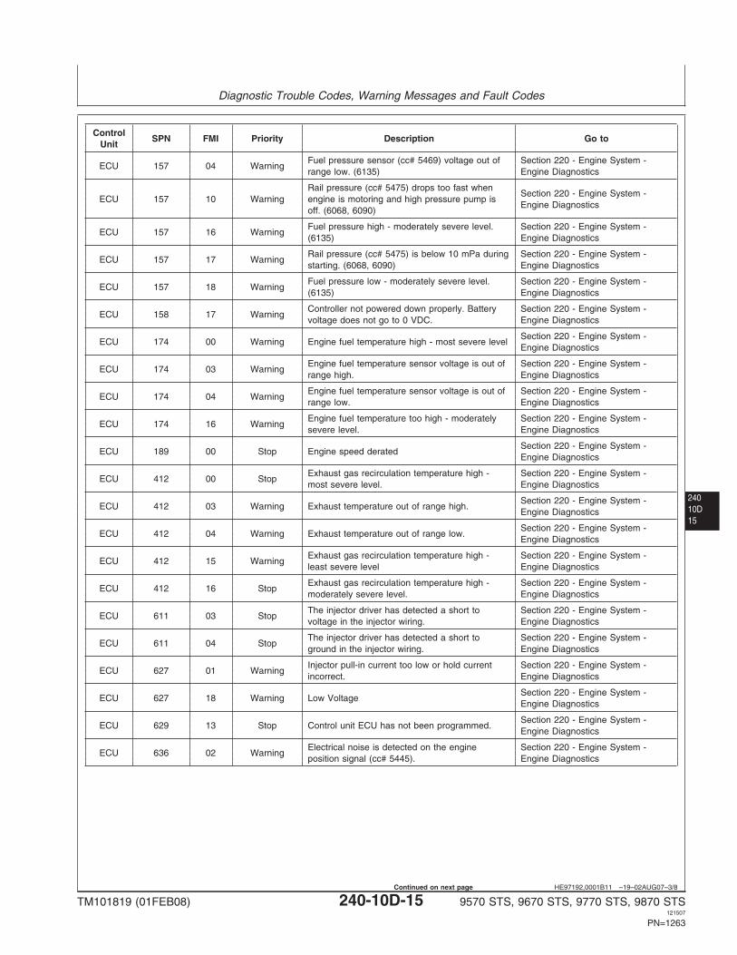
ControlSPN FMI Priority Description Go to
Unit
Fuel pressure sensor (cc# 5469) voltage out of Section 220 - Engine System -ECU 157 04 Warning
range low. (6135) Engine Diagnostics
Rail pressure (cc# 5475) drops too fast whenSection 220 - Engine System -
ECU 157 10 Warning engine is motoring and high pressure pump isEngine Diagnostics
off. (6068, 6090)
Fuel pressure high - moderately severe level. Section 220 - Engine System -ECU 157 16 Warning
(6135) Engine Diagnostics
Rail pressure (cc# 5475) is below 10 mPa during Section 220 - Engine System -ECU 157 17 Warning
starting. (6068, 6090) Engine Diagnostics
Fuel pressure low - moderately severe level. Section 220 - Engine System -ECU 157 18 Warning
(6135) Engine Diagnostics
Controller not powered down properly. Battery Section 220 - Engine System -ECU 158 17 Warning
voltage does not go to 0 VDC. Engine Diagnostics
Section 220 - Engine System -ECU 174 00 Warning Engine fuel temperature high - most severe level
Engine Diagnostics
Engine fuel temperature sensor voltage is out of Section 220 - Engine System -ECU 174 03 Warning
range high. Engine Diagnostics
Engine fuel temperature sensor voltage is out of Section 220 - Engine System -ECU 174 04 Warning
range low. Engine Diagnostics
Engine fuel temperature too high - moderately Section 220 - Engine System -ECU 174 16 Warning
severe level. Engine Diagnostics
Section 220 - Engine System -ECU 189 00 Stop Engine speed derated
Engine Diagnostics
Exhaust gas recirculation temperature high - Section 220 - Engine System -ECU 412 00 Stop
most severe level. Engine Diagnostics
Section 220 - Engine System -ECU 412 03 Warning Exhaust temperature out of range high.
Engine Diagnostics
Section 220 - Engine System -ECU 412 04 Warning Exhaust temperature out of range low.
Engine Diagnostics
Exhaust gas recirculation temperature high - Section 220 - Engine System -ECU 412 15 Warning
least severe level Engine Diagnostics
Exhaust gas recirculation temperature high - Section 220 - Engine System -ECU 412 16 Stop
moderately severe level. Engine Diagnostics
The injector driver has detected a short to Section 220 - Engine System -ECU 611 03 Stop
voltage in the injector wiring. Engine Diagnostics
The injector driver has detected a short to Section 220 - Engine System -ECU 611 04 Stop
ground in the injector wiring. Engine Diagnostics
Injector pull-in current too low or hold current Section 220 - Engine System -ECU 627 01 Warning
incorrect. Engine Diagnostics
Section 220 - Engine System -ECU 627 18 Warning Low Voltage
Engine Diagnostics
Section 220 - Engine System -ECU 629 13 Stop Control unit ECU has not been programmed.
Engine Diagnostics
Electrical noise is detected on the engine Section 220 - Engine System -ECU 636 02 Warning
position signal (cc# 5445). Engine Diagnostics
TM101819 (01FEB08) 240-10D-15 9570 STS, 9670 STS, 9770 STS, 9870 STS121507
PN=1263
Continued on next page
Diagnostic Trouble Codes, Warning Messages and Fault Codes
24010D
16
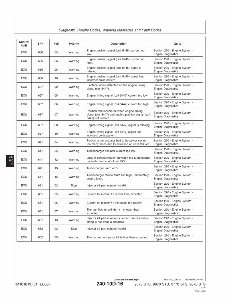
HE97192,0001B11 –19–02AUG07–4/8
ControlSPN FMI Priority Description Go to
Unit
Engine position signal (cc# 5445) current too Section 220 - Engine System -ECU 636 05 Warning
low. Engine Diagnostics
Engine position signal (cc# 5445) current too Section 220 - Engine System -ECU 636 06 Warning
high. Engine Diagnostics
Engine position signal (cc# 5445) signal is Section 220 - Engine System -ECU 636 08 Warning
missing. Engine Diagnostics
Engine position signal (cc# 5445) signal has Section 220 - Engine System -ECU 636 10 Warning
incorrect pulse pattern. Engine Diagnostics
Electrical noise detected on the engine timing Section 220 - Engine System -ECU 637 02 Warning
signal (cc# 5447). Engine Diagnostics
Section 220 - Engine System -ECU 637 05 Warning Engine timing signal (cc# 5447) current too low.
Engine Diagnostics
Section 220 - Engine System -ECU 637 06 Warning Engine timing signal (cc# 5447) current too high.
Engine Diagnostics
Position relationship between engine timingSection 220 - Engine System -
ECU 637 07 Warning signal (cc# 5447) and engine position signal (cc#Engine Diagnostics
5445) not correct.
Section 220 - Engine System -ECU 637 08 Warning Engine timing signal (cc# 5447) signal is missing.
Engine Diagnostics
Engine timing signal (cc# 5447) signal has Section 220 - Engine System -ECU 637 10 Warning
incorrect pulse pattern. Engine Diagnostics
Turbocharger actuator had to be power cycled Section 220 - Engine System -ECU 641 04 Warning
too many times due to actuation or learn failures. Engine Diagnostics
Section 220 - Engine System -ECU 641 05 Warning Turbocharger actuator current too low.
Engine Diagnostics
Loss of communication between the turbocharger Section 220 - Engine System -ECU 641 12 Warning
controller and control unit ECU. Engine Diagnostics
Section 220 - Engine System -ECU 641 13 Warning Turbocharger learn error.
Engine Diagnostics
Turbocharger temperature too high - moderately Section 220 - Engine System -ECU 641 16 Warning
severe level. Engine Diagnostics
Section 220 - Engine System -ECU 651 02 Stop Injector #1 part number invalid.
Engine Diagnostics
Section 220 - Engine System -ECU 651 05 Warning Current to injector #1 is less than expected.
Engine Diagnostics
Section 220 - Engine System -ECU 651 06 Warning Current to injector #1 increases too rapidly.
Engine Diagnostics
The fuel flow to cylinder #1 is lower than Section 220 - Engine System -ECU 651 07 Warning
expected. Engine Diagnostics
Injector #1 part number is correct but calibration Section 220 - Engine System -ECU 651 13 Warning
string is not what is expected. Engine Diagnostics
Section 220 - Engine System -ECU 652 02 Stop Injector #2 part number invalid
Engine Diagnostics
Section 220 - Engine System -ECU 652 05 Warning The current to injector #2 is less than expected.
Engine Diagnostics
TM101819 (01FEB08) 240-10D-16 9570 STS, 9670 STS, 9770 STS, 9870 STS121507
PN=1264
Continued on next page
Diagnostic Trouble Codes, Warning Messages and Fault Codes
24010D17
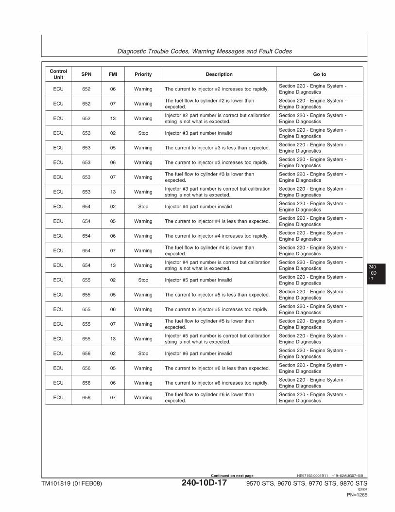
HE97192,0001B11 –19–02AUG07–5/8
ControlSPN FMI Priority Description Go to
Unit
Section 220 - Engine System -ECU 652 06 Warning The current to injector #2 increases too rapidly.
Engine Diagnostics
The fuel flow to cylinder #2 is lower than Section 220 - Engine System -ECU 652 07 Warning
expected. Engine Diagnostics
Injector #2 part number is correct but calibration Section 220 - Engine System -ECU 652 13 Warning
string is not what is expected. Engine Diagnostics
Section 220 - Engine System -ECU 653 02 Stop Injector #3 part number invalid
Engine Diagnostics
Section 220 - Engine System -ECU 653 05 Warning The current to injector #3 is less than expected.
Engine Diagnostics
Section 220 - Engine System -ECU 653 06 Warning The current to injector #3 increases too rapidly.
Engine Diagnostics
The fuel flow to cylinder #3 is lower than Section 220 - Engine System -ECU 653 07 Warning
expected. Engine Diagnostics
Injector #3 part number is correct but calibration Section 220 - Engine System -ECU 653 13 Warning
string is not what is expected. Engine Diagnostics
Section 220 - Engine System -ECU 654 02 Stop Injector #4 part number invalid
Engine Diagnostics
Section 220 - Engine System -ECU 654 05 Warning The current to injector #4 is less than expected.
Engine Diagnostics
Section 220 - Engine System -ECU 654 06 Warning The current to injector #4 increases too rapidly.
Engine Diagnostics
The fuel flow to cylinder #4 is lower than Section 220 - Engine System -ECU 654 07 Warning
expected. Engine Diagnostics
Injector #4 part number is correct but calibration Section 220 - Engine System -ECU 654 13 Warning
string is not what is expected. Engine Diagnostics
Section 220 - Engine System -ECU 655 02 Stop Injector #5 part number invalid
Engine Diagnostics
Section 220 - Engine System -ECU 655 05 Warning The current to injector #5 is less than expected.
Engine Diagnostics
Section 220 - Engine System -ECU 655 06 Warning The current to injector #5 increases too rapidly.
Engine Diagnostics
The fuel flow to cylinder #5 is lower than Section 220 - Engine System -ECU 655 07 Warning
expected. Engine Diagnostics
Injector #5 part number is correct but calibration Section 220 - Engine System -ECU 655 13 Warning
string is not what is expected. Engine Diagnostics
Section 220 - Engine System -ECU 656 02 Stop Injector #6 part number invalid
Engine Diagnostics
Section 220 - Engine System -ECU 656 05 Warning The current to injector #6 is less than expected.
Engine Diagnostics
Section 220 - Engine System -ECU 656 06 Warning The current to injector #6 increases too rapidly.
Engine Diagnostics
The fuel flow to cylinder #6 is lower than Section 220 - Engine System -ECU 656 07 Warning
expected. Engine Diagnostics
TM101819 (01FEB08) 240-10D-17 9570 STS, 9670 STS, 9770 STS, 9870 STS121507
PN=1265
Continued on next page
Diagnostic Trouble Codes, Warning Messages and Fault Codes
24010D
18
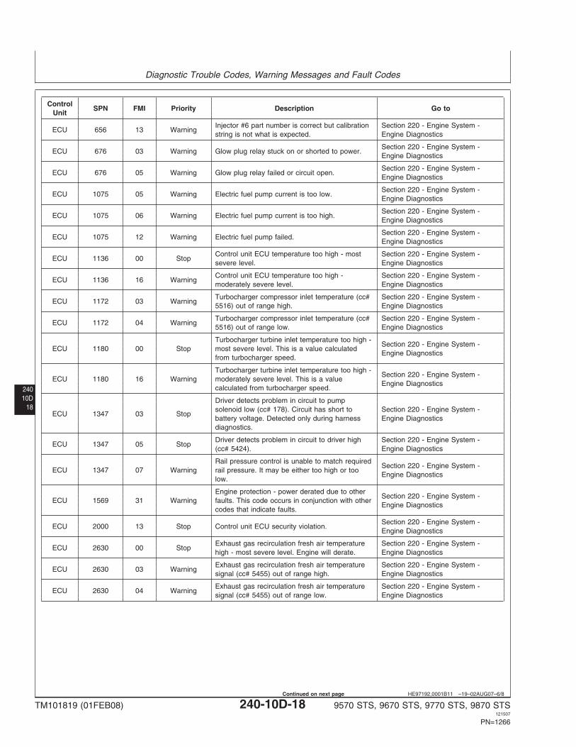
HE97192,0001B11 –19–02AUG07–6/8
ControlSPN FMI Priority Description Go to
Unit
Injector #6 part number is correct but calibration Section 220 - Engine System -ECU 656 13 Warning
string is not what is expected. Engine Diagnostics
Section 220 - Engine System -ECU 676 03 Warning Glow plug relay stuck on or shorted to power.
Engine Diagnostics
Section 220 - Engine System -ECU 676 05 Warning Glow plug relay failed or circuit open.
Engine Diagnostics
Section 220 - Engine System -ECU 1075 05 Warning Electric fuel pump current is too low.
Engine Diagnostics
Section 220 - Engine System -ECU 1075 06 Warning Electric fuel pump current is too high.
Engine Diagnostics
Section 220 - Engine System -ECU 1075 12 Warning Electric fuel pump failed.
Engine Diagnostics
Control unit ECU temperature too high - most Section 220 - Engine System -ECU 1136 00 Stop
severe level. Engine Diagnostics
Control unit ECU temperature too high - Section 220 - Engine System -ECU 1136 16 Warning
moderately severe level. Engine Diagnostics
Turbocharger compressor inlet temperature (cc# Section 220 - Engine System -ECU 1172 03 Warning
5516) out of range high. Engine Diagnostics
Turbocharger compressor inlet temperature (cc# Section 220 - Engine System -ECU 1172 04 Warning
5516) out of range low. Engine Diagnostics
Turbocharger turbine inlet temperature too high -Section 220 - Engine System -
ECU 1180 00 Stop most severe level. This is a value calculatedEngine Diagnostics
from turbocharger speed.
Turbocharger turbine inlet temperature too high -Section 220 - Engine System -
ECU 1180 16 Warning moderately severe level. This is a valueEngine Diagnostics
calculated from turbocharger speed.
Driver detects problem in circuit to pumpsolenoid low (cc# 178). Circuit has short to Section 220 - Engine System -
ECU 1347 03 Stopbattery voltage. Detected only during harness Engine Diagnosticsdiagnostics.
Driver detects problem in circuit to driver high Section 220 - Engine System -ECU 1347 05 Stop
(cc# 5424). Engine Diagnostics
Rail pressure control is unable to match requiredSection 220 - Engine System -
ECU 1347 07 Warning rail pressure. It may be either too high or tooEngine Diagnostics
low.
Engine protection - power derated due to otherSection 220 - Engine System -
ECU 1569 31 Warning faults. This code occurs in conjunction with otherEngine Diagnostics
codes that indicate faults.
Section 220 - Engine System -ECU 2000 13 Stop Control unit ECU security violation.
Engine Diagnostics
Exhaust gas recirculation fresh air temperature Section 220 - Engine System -ECU 2630 00 Stop
high - most severe level. Engine will derate. Engine Diagnostics
Exhaust gas recirculation fresh air temperature Section 220 - Engine System -ECU 2630 03 Warning
signal (cc# 5455) out of range high. Engine Diagnostics
Exhaust gas recirculation fresh air temperature Section 220 - Engine System -ECU 2630 04 Warning
signal (cc# 5455) out of range low. Engine Diagnostics
TM101819 (01FEB08) 240-10D-18 9570 STS, 9670 STS, 9770 STS, 9870 STS121507
PN=1266
Continued on next page
Diagnostic Trouble Codes, Warning Messages and Fault Codes
24010D19
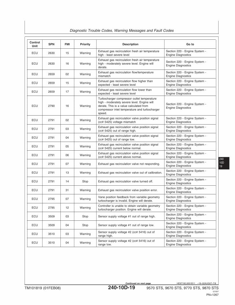
HE97192,0001B11 –19–02AUG07–7/8
ControlSPN FMI Priority Description Go to
Unit
Exhaust gas recirculation fresh air temperature Section 220 - Engine System -ECU 2630 15 Warning
high - least severe level Engine Diagnostics
Exhaust gas recirculation fresh air temperatureSection 220 - Engine System -
ECU 2630 16 Warning high - moderately severe level. Engine willEngine Diagnostics
derate.
Exhaust gas recirculation flow/temperature Section 220 - Engine System -ECU 2659 02 Warning
mismatch Engine Diagnostics
Exhaust gas recirculation flow higher than Section 220 - Engine System -ECU 2659 15 Warning
expected - least severe level Engine Diagnostics
Exhaust gas recirculation flow lower than Section 220 - Engine System -ECU 2659 17 Warning
expected - least severe level Engine Diagnostics
Turbocharger compressor outlet temperaturehigh - moderately severe level. Engine will
Section 220 - Engine System -ECU 2790 16 Warning derate. This is a value calculated from
Engine Diagnosticscompressor inlet temperature and turbochargerspeed.
Exhaust gas recirculation valve position signal Section 220 - Engine System -ECU 2791 02 Warning
(cc# 5425) voltage mismatch Engine Diagnostics
Exhaust gas recirculation valve position signal Section 220 - Engine System -ECU 2791 03 Warning
(cc# 5425) out of range high. Engine Diagnostics
Exhaust gas recirculation valve position signal Section 220 - Engine System -ECU 2791 04 Warning
(cc# 5425) out of range low. Engine Diagnostics
Exhaust gas recirculation valve position signal Section 220 - Engine System -ECU 2791 05 Warning
(cc# 5425) current below normal. Engine Diagnostics
Exhaust gas recirculation valve position signal Section 220 - Engine System -ECU 2791 06 Warning
(cc# 5425) current above normal. Engine Diagnostics
Section 220 - Engine System -ECU 2791 07 Warning Exhaust gas recirculation valve not responding.
Engine Diagnostics
Section 220 - Engine System -ECU 2791 13 Warning Exhaust gas recirculation valve out of calibration.
Engine Diagnostics
Section 220 - Engine System -ECU 2791 14 Stop Exhaust gas recirculation valve turned off.
Engine Diagnostics
Section 220 - Engine System -ECU 2791 31 Warning Exhaust gas recirculation valve position error.
Engine Diagnostics
Vane position feedback from variable geometry Section 220 - Engine System -ECU 2795 07 Warning
turbocharger is invalid. Engine will derate. Engine Diagnostics
Controller is unable to obtain variable geometry Section 220 - Engine System -ECU 2795 12 Warning
turbocharger position. Engine will derate. Engine Diagnostics
Section 220 - Engine System -ECU 3509 03 Stop Sensor supply voltage #1 out of range high.
Engine Diagnostics
Section 220 - Engine System -ECU 3509 04 Stop Sensor supply voltage #1 out of range low.
Engine Diagnostics
Sensor supply voltage #2 (cc# 5416) out of Section 220 - Engine System -ECU 3510 03 Warning
range high. Engine Diagnostics
Sensor supply voltage #2 (cc# 5416) out of Section 220 - Engine System -ECU 3510 04 Warning
range low. Engine Diagnostics
TM101819 (01FEB08) 240-10D-19 9570 STS, 9670 STS, 9770 STS, 9870 STS121507
PN=1267
Continued on next page
Diagnostic Trouble Codes, Warning Messages and Fault Codes
24010D
20
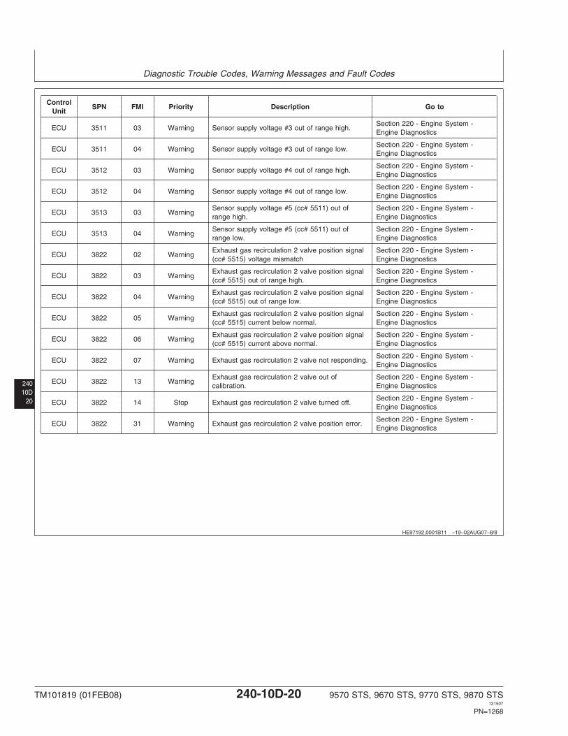
HE97192,0001B11 –19–02AUG07–8/8
ControlSPN FMI Priority Description Go to
Unit
Section 220 - Engine System -ECU 3511 03 Warning Sensor supply voltage #3 out of range high.
Engine Diagnostics
Section 220 - Engine System -ECU 3511 04 Warning Sensor supply voltage #3 out of range low.
Engine Diagnostics
Section 220 - Engine System -ECU 3512 03 Warning Sensor supply voltage #4 out of range high.
Engine Diagnostics
Section 220 - Engine System -ECU 3512 04 Warning Sensor supply voltage #4 out of range low.
Engine Diagnostics
Sensor supply voltage #5 (cc# 5511) out of Section 220 - Engine System -ECU 3513 03 Warning
range high. Engine Diagnostics
Sensor supply voltage #5 (cc# 5511) out of Section 220 - Engine System -ECU 3513 04 Warning
range low. Engine Diagnostics
Exhaust gas recirculation 2 valve position signal Section 220 - Engine System -ECU 3822 02 Warning
(cc# 5515) voltage mismatch Engine Diagnostics
Exhaust gas recirculation 2 valve position signal Section 220 - Engine System -ECU 3822 03 Warning
(cc# 5515) out of range high. Engine Diagnostics
Exhaust gas recirculation 2 valve position signal Section 220 - Engine System -ECU 3822 04 Warning
(cc# 5515) out of range low. Engine Diagnostics
Exhaust gas recirculation 2 valve position signal Section 220 - Engine System -ECU 3822 05 Warning
(cc# 5515) current below normal. Engine Diagnostics
Exhaust gas recirculation 2 valve position signal Section 220 - Engine System -ECU 3822 06 Warning
(cc# 5515) current above normal. Engine Diagnostics
Section 220 - Engine System -ECU 3822 07 Warning Exhaust gas recirculation 2 valve not responding.
Engine Diagnostics
Exhaust gas recirculation 2 valve out of Section 220 - Engine System -ECU 3822 13 Warning
calibration. Engine Diagnostics
Section 220 - Engine System -ECU 3822 14 Stop Exhaust gas recirculation 2 valve turned off.
Engine Diagnostics
Section 220 - Engine System -ECU 3822 31 Warning Exhaust gas recirculation 2 valve position error.
Engine Diagnostics
TM101819 (01FEB08) 240-10D-20 9570 STS, 9670 STS, 9770 STS, 9870 STS121507
PN=1268
Diagnostic Trouble Codes, Warning Messages and Fault Codes
24010D21
DJ36871,00006D3 –19–05JUN07–1/1
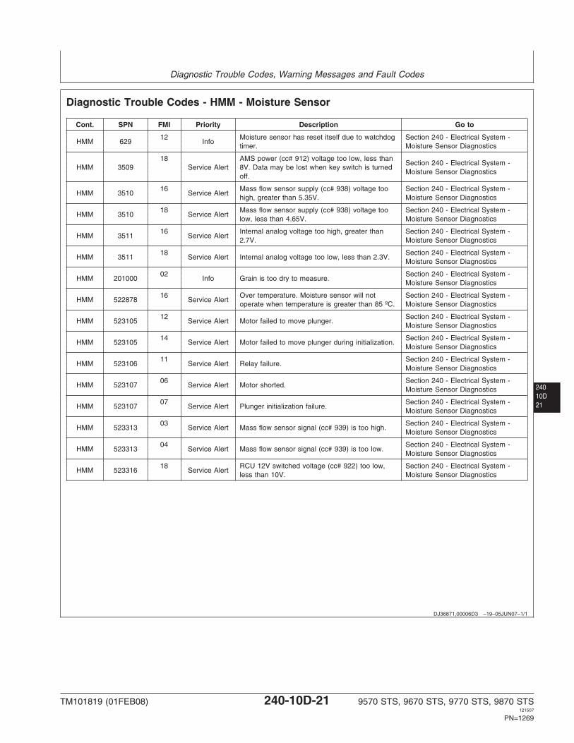
Diagnostic Trouble Codes - HMM - Moisture Sensor
Cont. SPN FMI Priority Description Go to
12 Moisture sensor has reset itself due to watchdog Section 240 - Electrical System -HMM 629 Info
timer. Moisture Sensor Diagnostics
18 AMS power (cc# 912) voltage too low, less thanSection 240 - Electrical System -
HMM 3509 Service Alert 8V. Data may be lost when key switch is turnedMoisture Sensor Diagnostics
off.
16 Mass flow sensor supply (cc# 938) voltage too Section 240 - Electrical System -HMM 3510 Service Alert
high, greater than 5.35V. Moisture Sensor Diagnostics
18 Mass flow sensor supply (cc# 938) voltage too Section 240 - Electrical System -HMM 3510 Service Alert
low, less than 4.65V. Moisture Sensor Diagnostics
16 Internal analog voltage too high, greater than Section 240 - Electrical System -HMM 3511 Service Alert
2.7V. Moisture Sensor Diagnostics
18 Section 240 - Electrical System -HMM 3511 Service Alert Internal analog voltage too low, less than 2.3V.
Moisture Sensor Diagnostics
02 Section 240 - Electrical System -HMM 201000 Info Grain is too dry to measure.
Moisture Sensor Diagnostics
16 Over temperature. Moisture sensor will not Section 240 - Electrical System -HMM 522878 Service Alert
operate when temperature is greater than 85 ºC. Moisture Sensor Diagnostics
12 Section 240 - Electrical System -HMM 523105 Service Alert Motor failed to move plunger.
Moisture Sensor Diagnostics
14 Section 240 - Electrical System -HMM 523105 Service Alert Motor failed to move plunger during initialization.
Moisture Sensor Diagnostics
11 Section 240 - Electrical System -HMM 523106 Service Alert Relay failure.
Moisture Sensor Diagnostics
06 Section 240 - Electrical System -HMM 523107 Service Alert Motor shorted.
Moisture Sensor Diagnostics
07 Section 240 - Electrical System -HMM 523107 Service Alert Plunger initialization failure.
Moisture Sensor Diagnostics
03 Section 240 - Electrical System -HMM 523313 Service Alert Mass flow sensor signal (cc# 939) is too high.
Moisture Sensor Diagnostics
04 Section 240 - Electrical System -HMM 523313 Service Alert Mass flow sensor signal (cc# 939) is too low.
Moisture Sensor Diagnostics
18 RCU 12V switched voltage (cc# 922) too low, Section 240 - Electrical System -HMM 523316 Service Alert
less than 10V. Moisture Sensor Diagnostics
TM101819 (01FEB08) 240-10D-21 9570 STS, 9670 STS, 9770 STS, 9870 STS121507
PN=1269
Diagnostic Trouble Codes, Warning Messages and Fault Codes
24010D
22
HE97192,0001B13 –19–05DEC07–1/18
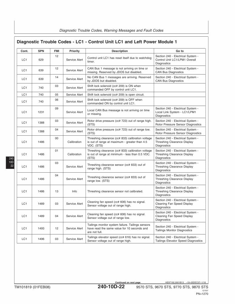
Diagnostic Trouble Codes - LC1 - Control Unit LC1 and Left Power Module 1
Cont. SPN FMI Priority Description Go to
12 Section 240 - Electrical System -Control unit LC1 has reset itself due to watchdog
LC1 629 Service Alert Control Unit LC1/LPM1 Overalltimer.
Diagnostics
12 CAN Bus 1 message is not arriving on time or Section 240 - Electrical System -LC1 639 Service Alert
missing. Reserved by JDOS but disabled. CAN Bus Diagnostics
14 No CAN Bus 1 messages are arriving. Reserved Section 240 - Electrical System -LC1 639 Service Alert
by JDOS but disabled. CAN Bus Diagnostics
03 Shift lock solenoid (cc# 209) is ON whenLC1 740 Service Alert
commanded OFF by control unit LC1.
LC1 740 05 Service Alert Shift lock solenoid (cc# 209) is open circuit.
06 Shift lock solenoid (cc# 209) is OFF whenLC1 740 Service Alert
commanded ON by control unit LC1.
09 Section 240 - Electrical System -Local CAN Bus message is not arriving on time
LC1 1231 Service Alert Local Link System - LC1/LPM1or missing.
Diagnostics
03 Rotor drive pressure (cc# 723) out of range high. Section 240 - Electrical System -LC1 1388 Service Alert
(STS) Rotor Pressure Sensor Diagnostics
04 Rotor drive pressure (cc# 723) out of range low. Section 240 - Electrical System -LC1 1388 Service Alert
(STS) Rotor Pressure Sensor Diagnostics
00 Threshing clearance (cc# 833) calibration voltage Section 240 - Electrical System -LC1 1486 Calibration is out of range at maximum - greater than 4.5 Threshing Clearance Display
VDC. (STS) Diagnostics
01 Threshing clearance (cc# 833) calibration voltage Section 240 - Electrical System -LC1 1486 Calibration is out of range at minimum - less than 0.5 VDC. Threshing Clearance Display
(STS) Diagnostics
03 Section 240 - Electrical System -Threshing clearance sensor (cc# 833) out of
LC1 1486 Service Alert Threshing Clearance Displayrange high. (STS)
Diagnostics
04 Section 240 - Electrical System -Threshing clearance sensor (cc# 833) out of
LC1 1486 Service Alert Threshing Clearance Displayrange low. (STS)
Diagnostics
Section 240 - Electrical System -LC1 1486 13 Info Threshing clearance sensor not calibrated. Threshing Clearance Display
Diagnostics
Section 240 - Electrical System -Cleaning fan speed (cc# 606) has no signal.
LC1 1489 03 Service Alert Cleaning Fan Speed DisplaySensor voltage out of range high.
Diagnostics
Section 240 - Electrical System -Cleaning fan speed (cc# 606) has no signal.
LC1 1489 04 Service Alert Cleaning Fan Speed DisplaySensor voltage out of range low.
Diagnostics
Tailings monitor system failure. Tailings sensorsSection 240 - Electrical System -
LC1 1493 12 Service Alert have read the same value for 10 seconds andTailings Monitor Diagnostics
are not full.
Tailings elevator speed (cc# 616) has no signal. Section 240 - Electrical System -LC1 1496 03 Service Alert
Sensor voltage out of range high. Tailings Elevator Speed Diagnostics
TM101819 (01FEB08) 240-10D-22 9570 STS, 9670 STS, 9770 STS, 9870 STS121507
PN=1270
Continued on next page
Diagnostic Trouble Codes, Warning Messages and Fault Codes
24010D23
HE97192,0001B13 –19–05DEC07–2/18
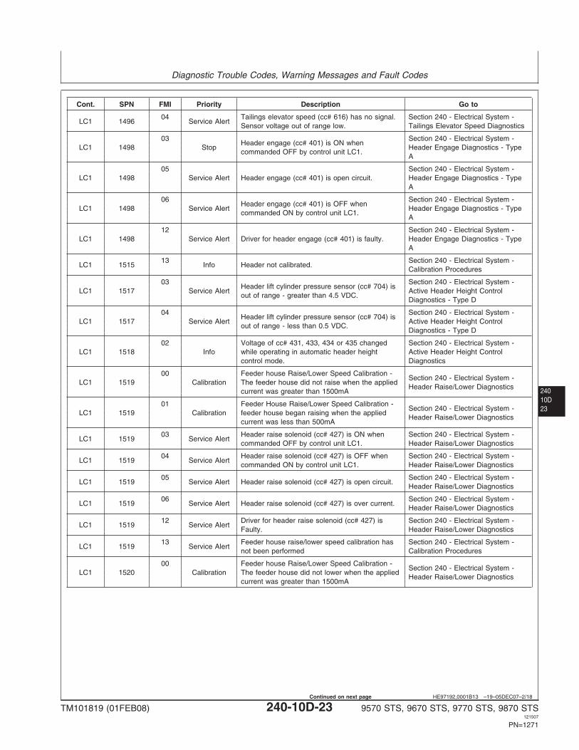
Cont. SPN FMI Priority Description Go to
04 Tailings elevator speed (cc# 616) has no signal. Section 240 - Electrical System -LC1 1496 Service Alert
Sensor voltage out of range low. Tailings Elevator Speed Diagnostics
03 Section 240 - Electrical System -Header engage (cc# 401) is ON when
LC1 1498 Stop Header Engage Diagnostics - Typecommanded OFF by control unit LC1.
A
05 Section 240 - Electrical System -LC1 1498 Service Alert Header engage (cc# 401) is open circuit. Header Engage Diagnostics - Type
A
06 Section 240 - Electrical System -Header engage (cc# 401) is OFF when
LC1 1498 Service Alert Header Engage Diagnostics - Typecommanded ON by control unit LC1.
A
12 Section 240 - Electrical System -LC1 1498 Service Alert Driver for header engage (cc# 401) is faulty. Header Engage Diagnostics - Type
A
13 Section 240 - Electrical System -LC1 1515 Info Header not calibrated.
Calibration Procedures
03 Section 240 - Electrical System -Header lift cylinder pressure sensor (cc# 704) is
LC1 1517 Service Alert Active Header Height Controlout of range - greater than 4.5 VDC.
Diagnostics - Type D
04 Section 240 - Electrical System -Header lift cylinder pressure sensor (cc# 704) is
LC1 1517 Service Alert Active Header Height Controlout of range - less than 0.5 VDC.
Diagnostics - Type D
02 Voltage of cc# 431, 433, 434 or 435 changed Section 240 - Electrical System -LC1 1518 Info while operating in automatic header height Active Header Height Control
control mode. Diagnostics
00 Feeder house Raise/Lower Speed Calibration -Section 240 - Electrical System -
LC1 1519 Calibration The feeder house did not raise when the appliedHeader Raise/Lower Diagnostics
current was greater than 1500mA
01 Feeder House Raise/Lower Speed Calibration -Section 240 - Electrical System -
LC1 1519 Calibration feeder house began raising when the appliedHeader Raise/Lower Diagnostics
current was less than 500mA
03 Header raise solenoid (cc# 427) is ON when Section 240 - Electrical System -LC1 1519 Service Alert
commanded OFF by control unit LC1. Header Raise/Lower Diagnostics
04 Header raise solenoid (cc# 427) is OFF when Section 240 - Electrical System -LC1 1519 Service Alert
commanded ON by control unit LC1. Header Raise/Lower Diagnostics
05 Section 240 - Electrical System -LC1 1519 Service Alert Header raise solenoid (cc# 427) is open circuit.
Header Raise/Lower Diagnostics
06 Section 240 - Electrical System -LC1 1519 Service Alert Header raise solenoid (cc# 427) is over current.
Header Raise/Lower Diagnostics
12 Driver for header raise solenoid (cc# 427) is Section 240 - Electrical System -LC1 1519 Service Alert
Faulty. Header Raise/Lower Diagnostics
13 Feeder house raise/lower speed calibration has Section 240 - Electrical System -LC1 1519 Service Alert
not been performed Calibration Procedures
00 Feeder house Raise/Lower Speed Calibration -Section 240 - Electrical System -
LC1 1520 Calibration The feeder house did not lower when the appliedHeader Raise/Lower Diagnostics
current was greater than 1500mA
TM101819 (01FEB08) 240-10D-23 9570 STS, 9670 STS, 9770 STS, 9870 STS121507
PN=1271
Continued on next page
Diagnostic Trouble Codes, Warning Messages and Fault Codes
24010D
24
HE97192,0001B13 –19–05DEC07–3/18
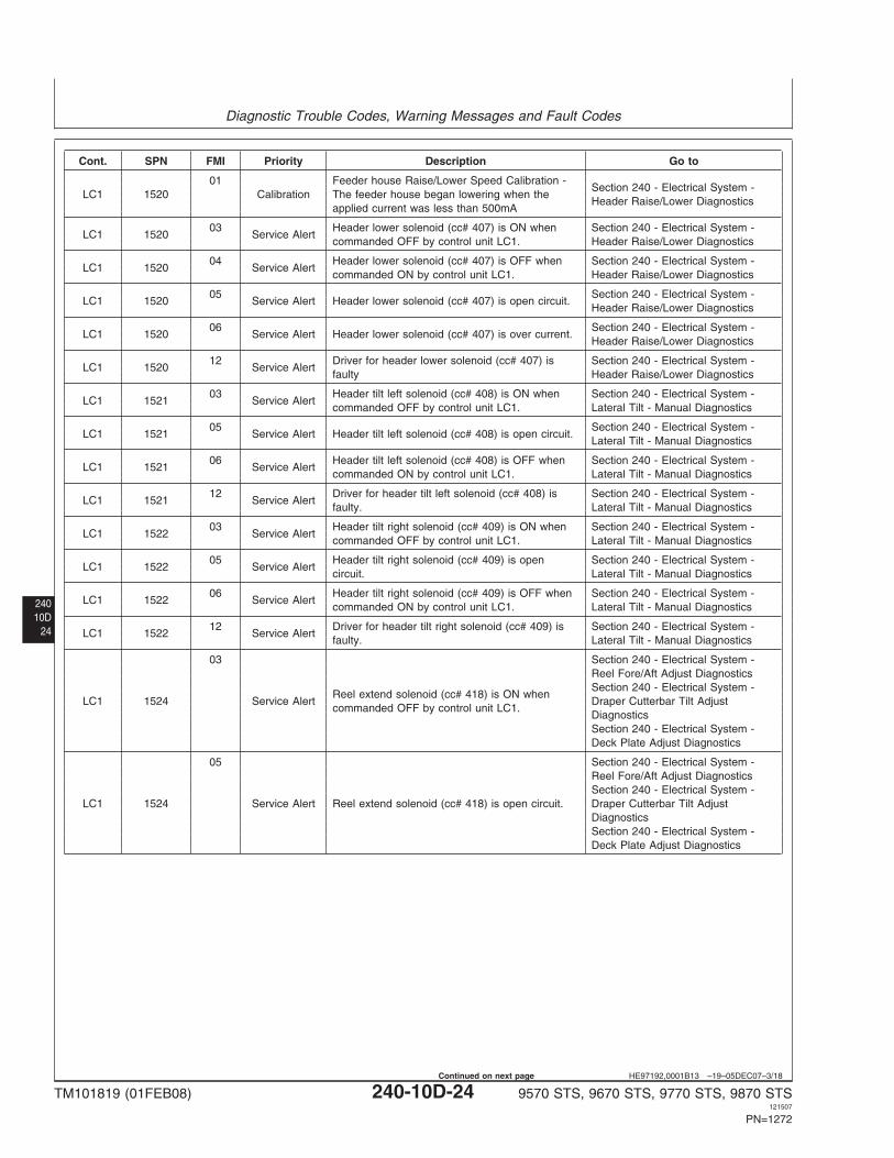
Cont. SPN FMI Priority Description Go to
01 Feeder house Raise/Lower Speed Calibration -Section 240 - Electrical System -
LC1 1520 Calibration The feeder house began lowering when theHeader Raise/Lower Diagnostics
applied current was less than 500mA
03 Header lower solenoid (cc# 407) is ON when Section 240 - Electrical System -LC1 1520 Service Alert
commanded OFF by control unit LC1. Header Raise/Lower Diagnostics
04 Header lower solenoid (cc# 407) is OFF when Section 240 - Electrical System -LC1 1520 Service Alert
commanded ON by control unit LC1. Header Raise/Lower Diagnostics
05 Section 240 - Electrical System -LC1 1520 Service Alert Header lower solenoid (cc# 407) is open circuit.
Header Raise/Lower Diagnostics
06 Section 240 - Electrical System -LC1 1520 Service Alert Header lower solenoid (cc# 407) is over current.
Header Raise/Lower Diagnostics
12 Driver for header lower solenoid (cc# 407) is Section 240 - Electrical System -LC1 1520 Service Alert
faulty Header Raise/Lower Diagnostics
03 Header tilt left solenoid (cc# 408) is ON when Section 240 - Electrical System -LC1 1521 Service Alert
commanded OFF by control unit LC1. Lateral Tilt - Manual Diagnostics
05 Section 240 - Electrical System -LC1 1521 Service Alert Header tilt left solenoid (cc# 408) is open circuit.
Lateral Tilt - Manual Diagnostics
06 Header tilt left solenoid (cc# 408) is OFF when Section 240 - Electrical System -LC1 1521 Service Alert
commanded ON by control unit LC1. Lateral Tilt - Manual Diagnostics
12 Driver for header tilt left solenoid (cc# 408) is Section 240 - Electrical System -LC1 1521 Service Alert
faulty. Lateral Tilt - Manual Diagnostics
03 Header tilt right solenoid (cc# 409) is ON when Section 240 - Electrical System -LC1 1522 Service Alert
commanded OFF by control unit LC1. Lateral Tilt - Manual Diagnostics
05 Header tilt right solenoid (cc# 409) is open Section 240 - Electrical System -LC1 1522 Service Alert
circuit. Lateral Tilt - Manual Diagnostics
06 Header tilt right solenoid (cc# 409) is OFF when Section 240 - Electrical System -LC1 1522 Service Alert
commanded ON by control unit LC1. Lateral Tilt - Manual Diagnostics
12 Driver for header tilt right solenoid (cc# 409) is Section 240 - Electrical System -LC1 1522 Service Alert
faulty. Lateral Tilt - Manual Diagnostics
03 Section 240 - Electrical System -Reel Fore/Aft Adjust DiagnosticsSection 240 - Electrical System -
Reel extend solenoid (cc# 418) is ON whenLC1 1524 Service Alert Draper Cutterbar Tilt Adjust
commanded OFF by control unit LC1.DiagnosticsSection 240 - Electrical System -Deck Plate Adjust Diagnostics
05 Section 240 - Electrical System -Reel Fore/Aft Adjust DiagnosticsSection 240 - Electrical System -
LC1 1524 Service Alert Reel extend solenoid (cc# 418) is open circuit. Draper Cutterbar Tilt AdjustDiagnosticsSection 240 - Electrical System -Deck Plate Adjust Diagnostics
TM101819 (01FEB08) 240-10D-24 9570 STS, 9670 STS, 9770 STS, 9870 STS121507
PN=1272
Continued on next page
Diagnostic Trouble Codes, Warning Messages and Fault Codes
24010D25
HE97192,0001B13 –19–05DEC07–4/18
Cont. SPN FMI Priority Description Go to
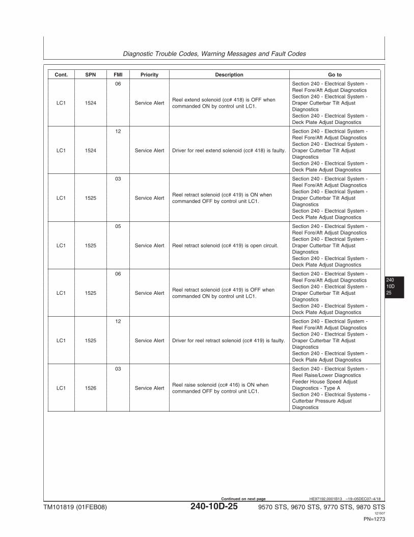
06 Section 240 - Electrical System -Reel Fore/Aft Adjust DiagnosticsSection 240 - Electrical System -
Reel extend solenoid (cc# 418) is OFF whenLC1 1524 Service Alert Draper Cutterbar Tilt Adjust
commanded ON by control unit LC1.DiagnosticsSection 240 - Electrical System -Deck Plate Adjust Diagnostics
12 Section 240 - Electrical System -Reel Fore/Aft Adjust DiagnosticsSection 240 - Electrical System -
LC1 1524 Service Alert Driver for reel extend solenoid (cc# 418) is faulty. Draper Cutterbar Tilt AdjustDiagnosticsSection 240 - Electrical System -Deck Plate Adjust Diagnostics
03 Section 240 - Electrical System -Reel Fore/Aft Adjust DiagnosticsSection 240 - Electrical System -
Reel retract solenoid (cc# 419) is ON whenLC1 1525 Service Alert Draper Cutterbar Tilt Adjust
commanded OFF by control unit LC1.DiagnosticsSection 240 - Electrical System -Deck Plate Adjust Diagnostics
05 Section 240 - Electrical System -Reel Fore/Aft Adjust DiagnosticsSection 240 - Electrical System -
LC1 1525 Service Alert Reel retract solenoid (cc# 419) is open circuit. Draper Cutterbar Tilt AdjustDiagnosticsSection 240 - Electrical System -Deck Plate Adjust Diagnostics
06 Section 240 - Electrical System -Reel Fore/Aft Adjust DiagnosticsSection 240 - Electrical System -
Reel retract solenoid (cc# 419) is OFF whenLC1 1525 Service Alert Draper Cutterbar Tilt Adjust
commanded ON by control unit LC1.DiagnosticsSection 240 - Electrical System -Deck Plate Adjust Diagnostics
12 Section 240 - Electrical System -Reel Fore/Aft Adjust DiagnosticsSection 240 - Electrical System -
LC1 1525 Service Alert Driver for reel retract solenoid (cc# 419) is faulty. Draper Cutterbar Tilt AdjustDiagnosticsSection 240 - Electrical System -Deck Plate Adjust Diagnostics
03 Section 240 - Electrical System -Reel Raise/Lower DiagnosticsFeeder House Speed Adjust
Reel raise solenoid (cc# 416) is ON whenLC1 1526 Service Alert Diagnostics - Type A
commanded OFF by control unit LC1.Section 240 - Electrical Systems -Cutterbar Pressure AdjustDiagnostics
TM101819 (01FEB08) 240-10D-25 9570 STS, 9670 STS, 9770 STS, 9870 STS121507
PN=1273
Continued on next page
Diagnostic Trouble Codes, Warning Messages and Fault Codes
24010D
26
HE97192,0001B13 –19–05DEC07–5/18
Cont. SPN FMI Priority Description Go to
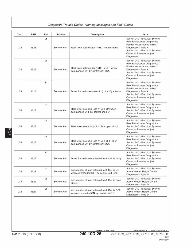
05 Section 240 - Electrical System -Reel Raise/Lower DiagnosticsFeeder House Speed Adjust
LC1 1526 Service Alert Reel raise solenoid (cc# 416) is open circuit. Diagnostics - Type ASection 240 - Electrical Systems -Cutterbar Pressure AdjustDiagnostics
06 Section 240 - Electrical System -Reel Raise/Lower DiagnosticsFeeder House Speed Adjust
Reel raise solenoid (cc# 416) is OFF whenLC1 1526 Service Alert Diagnostics - Type A
commanded ON by control unit LC1.Section 240 - Electrical Systems -Cutterbar Pressure AdjustDiagnostics
12 Section 240 - Electrical System -Reel Raise/Lower DiagnosticsFeeder House Speed Adjust
LC1 1526 Service Alert Driver for reel raise solenoid (cc# 416) is faulty. Diagnostics - Type ASection 240 - Electrical Systems -Cutterbar Pressure AdjustDiagnostics
03 Section 240 - Electrical System -Reel Raise/Lower Diagnostics
Reel lower solenoid (cc# 415) is ON whenLC1 1527 Service Alert Section 240 - Electrical Systems -
commanded OFF by control unit LC1.Cutterbar Pressure AdjustDiagnostics
05 Section 240 - Electrical System -Reel Raise/Lower Diagnostics
LC1 1527 Service Alert Reel lower solenoid (cc# 415) is open circuit. Section 240 - Electrical Systems -Cutterbar Pressure AdjustDiagnostics
06 Section 240 - Electrical System -Reel Raise/Lower Diagnostics
Reel lower solenoid (cc# 415) is OFF whenLC1 1527 Service Alert Section 240 - Electrical Systems -
commanded ON by control unit LC1.Cutterbar Pressure AdjustDiagnostics
12 Section 240 - Electrical System -Reel Raise/Lower Diagnostics
LC1 1527 Service Alert Driver for reel lower solenoid (cc# 415) is faulty. Section 240 - Electrical Systems -Cutterbar Pressure AdjustDiagnostics
03 Section 240 - Electrical System -Accumulator shutoff solenoid (cc# 484) is ON
LC1 1529 Service Alert Active Header Height Controlwhen commanded OFF by control unit LC1.
Diagnostics - Type D
05 Section 240 - Electrical System -Accumulator shutoff solenoid (cc# 484) is open
LC1 1529 Service Alert Active Header Height Controlcircuit.
Diagnostics - Type D
06 Section 240 - Electrical System -Accumulator shutoff solenoid (cc# 484) is OFF
LC1 1529 Service Alert Active Header Height Controlwhen commanded ON by control unit LC1.
Diagnostics - Type D
TM101819 (01FEB08) 240-10D-26 9570 STS, 9670 STS, 9770 STS, 9870 STS121507
PN=1274
Continued on next page
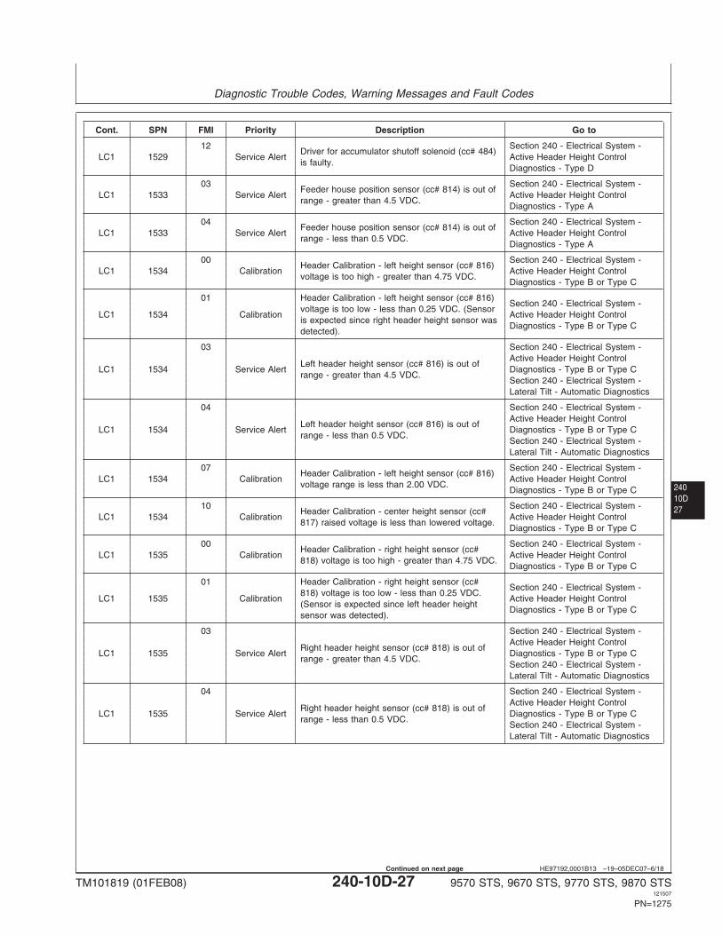
Diagnostic Trouble Codes, Warning Messages and Fault Codes
24010D27
HE97192,0001B13 –19–05DEC07–6/18
Cont. SPN FMI Priority Description Go to
12 Section 240 - Electrical System -Driver for accumulator shutoff solenoid (cc# 484)
LC1 1529 Service Alert Active Header Height Controlis faulty.
Diagnostics - Type D
03 Section 240 - Electrical System -Feeder house position sensor (cc# 814) is out of
LC1 1533 Service Alert Active Header Height Controlrange - greater than 4.5 VDC.
Diagnostics - Type A
04 Section 240 - Electrical System -Feeder house position sensor (cc# 814) is out of
LC1 1533 Service Alert Active Header Height Controlrange - less than 0.5 VDC.
Diagnostics - Type A
00 Section 240 - Electrical System -Header Calibration - left height sensor (cc# 816)
LC1 1534 Calibration Active Header Height Controlvoltage is too high - greater than 4.75 VDC.
Diagnostics - Type B or Type C
01 Header Calibration - left height sensor (cc# 816)Section 240 - Electrical System -
voltage is too low - less than 0.25 VDC. (SensorLC1 1534 Calibration Active Header Height Control
is expected since right header height sensor wasDiagnostics - Type B or Type C
detected).
03 Section 240 - Electrical System -Active Header Height Control
Left header height sensor (cc# 816) is out ofLC1 1534 Service Alert Diagnostics - Type B or Type C
range - greater than 4.5 VDC.Section 240 - Electrical System -Lateral Tilt - Automatic Diagnostics
04 Section 240 - Electrical System -Active Header Height Control
Left header height sensor (cc# 816) is out ofLC1 1534 Service Alert Diagnostics - Type B or Type C
range - less than 0.5 VDC.Section 240 - Electrical System -Lateral Tilt - Automatic Diagnostics
07 Section 240 - Electrical System -Header Calibration - left height sensor (cc# 816)
LC1 1534 Calibration Active Header Height Controlvoltage range is less than 2.00 VDC.
Diagnostics - Type B or Type C
10 Section 240 - Electrical System -Header Calibration - center height sensor (cc#
LC1 1534 Calibration Active Header Height Control817) raised voltage is less than lowered voltage.
Diagnostics - Type B or Type C
00 Section 240 - Electrical System -Header Calibration - right height sensor (cc#
LC1 1535 Calibration Active Header Height Control818) voltage is too high - greater than 4.75 VDC.
Diagnostics - Type B or Type C
01 Header Calibration - right height sensor (cc#Section 240 - Electrical System -
818) voltage is too low - less than 0.25 VDC.LC1 1535 Calibration Active Header Height Control
(Sensor is expected since left header heightDiagnostics - Type B or Type C
sensor was detected).
03 Section 240 - Electrical System -Active Header Height Control
Right header height sensor (cc# 818) is out ofLC1 1535 Service Alert Diagnostics - Type B or Type C
range - greater than 4.5 VDC.Section 240 - Electrical System -Lateral Tilt - Automatic Diagnostics
04 Section 240 - Electrical System -Active Header Height Control
Right header height sensor (cc# 818) is out ofLC1 1535 Service Alert Diagnostics - Type B or Type C
range - less than 0.5 VDC.Section 240 - Electrical System -Lateral Tilt - Automatic Diagnostics
TM101819 (01FEB08) 240-10D-27 9570 STS, 9670 STS, 9770 STS, 9870 STS121507
PN=1275
Continued on next page
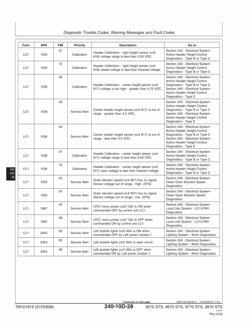
Diagnostic Trouble Codes, Warning Messages and Fault Codes
24010D
28
HE97192,0001B13 –19–05DEC07–7/18
Cont. SPN FMI Priority Description Go to
07 Section 240 - Electrical System -Header Calibration - right height sensor (cc#
LC1 1535 Calibration Active Header Height Control818) voltage range is less than 2.00 VDC.
Diagnostics - Type B or Type C
10 Section 240 - Electrical System -Header Calibration - right height sensor (cc#
LC1 1535 Calibration Active Header Height Control818) raised voltage is less than lowered voltage.
Diagnostics - Type B or Type C
00 Section 240 - Electrical System -Active Header Height Control
Header Calibration - center height sensor (cc# Diagnostics - Type B or Type CLC1 1536 Calibration
817) voltage is too high - greater than 4.75 VDC. Section 240 - Electrical System -Active Header Height ControlDiagnostics - Type E
03 Section 240 - Electrical System -Active Header Height Control
Center header height sensor (cc# 817) is out of Diagnostics - Type B or Type CLC1 1536 Service Alert
range - greater than 4.5 VDC. Section 240 - Electrical System -Active Header Height ControlDiagnostics - Type E
04 Section 240 - Electrical System -Active Header Height Control
Center header height sensor (cc# 817) is out of Diagnostics - Type B or Type CLC1 1536 Service Alert
range - less than 0.5 VDC. Section 240 - Electrical System -Active Header Height ControlDiagnostics - Type E
07 Section 240 - Electrical System -Header Calibration - center height sensor (cc#
LC1 1536 Calibration Active Header Height Control817) voltage range is less than 2.00 VDC.
Diagnostics - Type B or Type C
10 Section 240 - Electrical System -Header Calibration - center height sensor (cc#
LC1 1536 Calibration Active Header Height Control817) raise voltage is less than lowered voltage.
Diagnostics - Type B or Type C
03 Section 240 - Electrical System -Grain elevator speed (cc# 607) has no signal.
LC1 1554 Service Alert Clean Grain Elevator SpeedSensor voltage out of range - high. (STS)
Diagnostics
04 Section 240 - Electrical System -Grain elevator speed (cc# 607) has no signal.
LC1 1554 Service Alert Clean Grain Elevator SpeedSensor voltage out of range - low. (STS)
Diagnostics
03 Section 240 - Electrical System -LPC1 micro power (cc# 102) is ON when
LC1 1867 Service Alert Local Link System - LC1/LPM1commanded OFF by control unit LC1.
Diagnostics
06 Section 240 - Electrical System -LPC1 micro power (cc# 102) is OFF when
LC1 1867 Service Alert Local Link System - LC1/LPM1commanded ON by control unit LC1.
Diagnostics
03 Left stubble lights (cc# 564) is ON when Section 240 - Electrical System -LC1 2354 Service Alert
commanded OFF by Left power module 1. Lighting System - Work Diagnostics
05 Section 240 - Electrical System -LC1 2354 Service Alert Left stubble lights (cc# 564) is open circuit.
Lighting System - Work Diagnostics
06 Left stubble lights (cc# 564) is OFF when Section 240 - Electrical System -LC1 2354 Service Alert
commanded ON by Left power module 1. Lighting System - Work Diagnostics
TM101819 (01FEB08) 240-10D-28 9570 STS, 9670 STS, 9770 STS, 9870 STS121507
PN=1276
Continued on next page
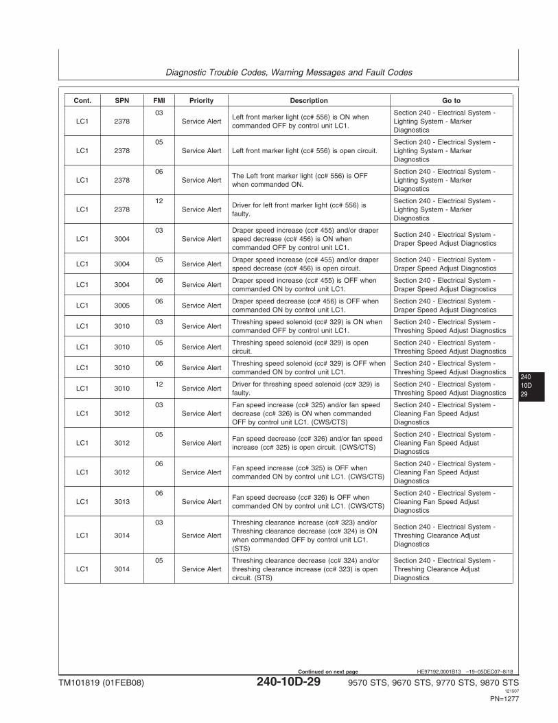
Diagnostic Trouble Codes, Warning Messages and Fault Codes
24010D29
HE97192,0001B13 –19–05DEC07–8/18
Cont. SPN FMI Priority Description Go to
03 Section 240 - Electrical System -Left front marker light (cc# 556) is ON when
LC1 2378 Service Alert Lighting System - Markercommanded OFF by control unit LC1.
Diagnostics
05 Section 240 - Electrical System -LC1 2378 Service Alert Left front marker light (cc# 556) is open circuit. Lighting System - Marker
Diagnostics
06 Section 240 - Electrical System -The Left front marker light (cc# 556) is OFF
LC1 2378 Service Alert Lighting System - Markerwhen commanded ON.
Diagnostics
12 Section 240 - Electrical System -Driver for left front marker light (cc# 556) is
LC1 2378 Service Alert Lighting System - Markerfaulty.
Diagnostics
03 Draper speed increase (cc# 455) and/or draperSection 240 - Electrical System -
LC1 3004 Service Alert speed decrease (cc# 456) is ON whenDraper Speed Adjust Diagnostics
commanded OFF by control unit LC1.
05 Draper speed increase (cc# 455) and/or draper Section 240 - Electrical System -LC1 3004 Service Alert
speed decrease (cc# 456) is open circuit. Draper Speed Adjust Diagnostics
06 Draper speed increase (cc# 455) is OFF when Section 240 - Electrical System -LC1 3004 Service Alert
commanded ON by control unit LC1. Draper Speed Adjust Diagnostics
06 Draper speed decrease (cc# 456) is OFF when Section 240 - Electrical System -LC1 3005 Service Alert
commanded ON by control unit LC1. Draper Speed Adjust Diagnostics
03 Threshing speed solenoid (cc# 329) is ON when Section 240 - Electrical System -LC1 3010 Service Alert
commanded OFF by control unit LC1. Threshing Speed Adjust Diagnostics
05 Threshing speed solenoid (cc# 329) is open Section 240 - Electrical System -LC1 3010 Service Alert
circuit. Threshing Speed Adjust Diagnostics
06 Threshing speed solenoid (cc# 329) is OFF when Section 240 - Electrical System -LC1 3010 Service Alert
commanded ON by control unit LC1. Threshing Speed Adjust Diagnostics
12 Driver for threshing speed solenoid (cc# 329) is Section 240 - Electrical System -LC1 3010 Service Alert
faulty. Threshing Speed Adjust Diagnostics
03 Fan speed increase (cc# 325) and/or fan speed Section 240 - Electrical System -LC1 3012 Service Alert decrease (cc# 326) is ON when commanded Cleaning Fan Speed Adjust
OFF by control unit LC1. (CWS/CTS) Diagnostics
05 Section 240 - Electrical System -Fan speed decrease (cc# 326) and/or fan speed
LC1 3012 Service Alert Cleaning Fan Speed Adjustincrease (cc# 325) is open circuit. (CWS/CTS)
Diagnostics
06 Section 240 - Electrical System -Fan speed increase (cc# 325) is OFF when
LC1 3012 Service Alert Cleaning Fan Speed Adjustcommanded ON by control unit LC1. (CWS/CTS)
Diagnostics
06 Section 240 - Electrical System -Fan speed decrease (cc# 326) is OFF when
LC1 3013 Service Alert Cleaning Fan Speed Adjustcommanded ON by control unit LC1. (CWS/CTS)
Diagnostics
03 Threshing clearance increase (cc# 323) and/orSection 240 - Electrical System -
Threshing clearance decrease (cc# 324) is ONLC1 3014 Service Alert Threshing Clearance Adjust
when commanded OFF by control unit LC1.Diagnostics
(STS)
05 Threshing clearance decrease (cc# 324) and/or Section 240 - Electrical System -LC1 3014 Service Alert threshing clearance increase (cc# 323) is open Threshing Clearance Adjust
circuit. (STS) Diagnostics
TM101819 (01FEB08) 240-10D-29 9570 STS, 9670 STS, 9770 STS, 9870 STS121507
PN=1277
Continued on next page
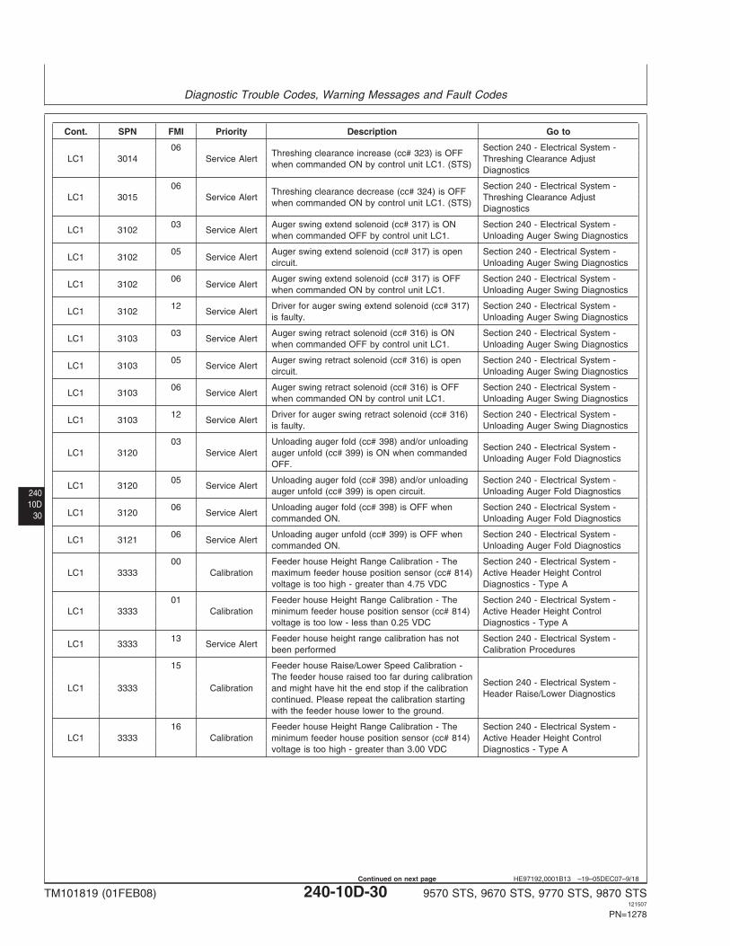
Diagnostic Trouble Codes, Warning Messages and Fault Codes
24010D
30
HE97192,0001B13 –19–05DEC07–9/18
Cont. SPN FMI Priority Description Go to
06 Section 240 - Electrical System -Threshing clearance increase (cc# 323) is OFF
LC1 3014 Service Alert Threshing Clearance Adjustwhen commanded ON by control unit LC1. (STS)
Diagnostics
06 Section 240 - Electrical System -Threshing clearance decrease (cc# 324) is OFF
LC1 3015 Service Alert Threshing Clearance Adjustwhen commanded ON by control unit LC1. (STS)
Diagnostics
03 Auger swing extend solenoid (cc# 317) is ON Section 240 - Electrical System -LC1 3102 Service Alert
when commanded OFF by control unit LC1. Unloading Auger Swing Diagnostics
05 Auger swing extend solenoid (cc# 317) is open Section 240 - Electrical System -LC1 3102 Service Alert
circuit. Unloading Auger Swing Diagnostics
06 Auger swing extend solenoid (cc# 317) is OFF Section 240 - Electrical System -LC1 3102 Service Alert
when commanded ON by control unit LC1. Unloading Auger Swing Diagnostics
12 Driver for auger swing extend solenoid (cc# 317) Section 240 - Electrical System -LC1 3102 Service Alert
is faulty. Unloading Auger Swing Diagnostics
03 Auger swing retract solenoid (cc# 316) is ON Section 240 - Electrical System -LC1 3103 Service Alert
when commanded OFF by control unit LC1. Unloading Auger Swing Diagnostics
05 Auger swing retract solenoid (cc# 316) is open Section 240 - Electrical System -LC1 3103 Service Alert
circuit. Unloading Auger Swing Diagnostics
06 Auger swing retract solenoid (cc# 316) is OFF Section 240 - Electrical System -LC1 3103 Service Alert
when commanded ON by control unit LC1. Unloading Auger Swing Diagnostics
12 Driver for auger swing retract solenoid (cc# 316) Section 240 - Electrical System -LC1 3103 Service Alert
is faulty. Unloading Auger Swing Diagnostics
03 Unloading auger fold (cc# 398) and/or unloadingSection 240 - Electrical System -
LC1 3120 Service Alert auger unfold (cc# 399) is ON when commandedUnloading Auger Fold Diagnostics
OFF.
05 Unloading auger fold (cc# 398) and/or unloading Section 240 - Electrical System -LC1 3120 Service Alert
auger unfold (cc# 399) is open circuit. Unloading Auger Fold Diagnostics
06 Unloading auger fold (cc# 398) is OFF when Section 240 - Electrical System -LC1 3120 Service Alert
commanded ON. Unloading Auger Fold Diagnostics
06 Unloading auger unfold (cc# 399) is OFF when Section 240 - Electrical System -LC1 3121 Service Alert
commanded ON. Unloading Auger Fold Diagnostics
00 Feeder house Height Range Calibration - The Section 240 - Electrical System -LC1 3333 Calibration maximum feeder house position sensor (cc# 814) Active Header Height Control
voltage is too high - greater than 4.75 VDC Diagnostics - Type A
01 Feeder house Height Range Calibration - The Section 240 - Electrical System -LC1 3333 Calibration minimum feeder house position sensor (cc# 814) Active Header Height Control
voltage is too low - less than 0.25 VDC Diagnostics - Type A
13 Feeder house height range calibration has not Section 240 - Electrical System -LC1 3333 Service Alert
been performed Calibration Procedures
15 Feeder house Raise/Lower Speed Calibration -The feeder house raised too far during calibration
Section 240 - Electrical System -LC1 3333 Calibration and might have hit the end stop if the calibration
Header Raise/Lower Diagnosticscontinued. Please repeat the calibration startingwith the feeder house lower to the ground.
16 Feeder house Height Range Calibration - The Section 240 - Electrical System -LC1 3333 Calibration minimum feeder house position sensor (cc# 814) Active Header Height Control
voltage is too high - greater than 3.00 VDC Diagnostics - Type A
TM101819 (01FEB08) 240-10D-30 9570 STS, 9670 STS, 9770 STS, 9870 STS121507
PN=1278
Continued on next page
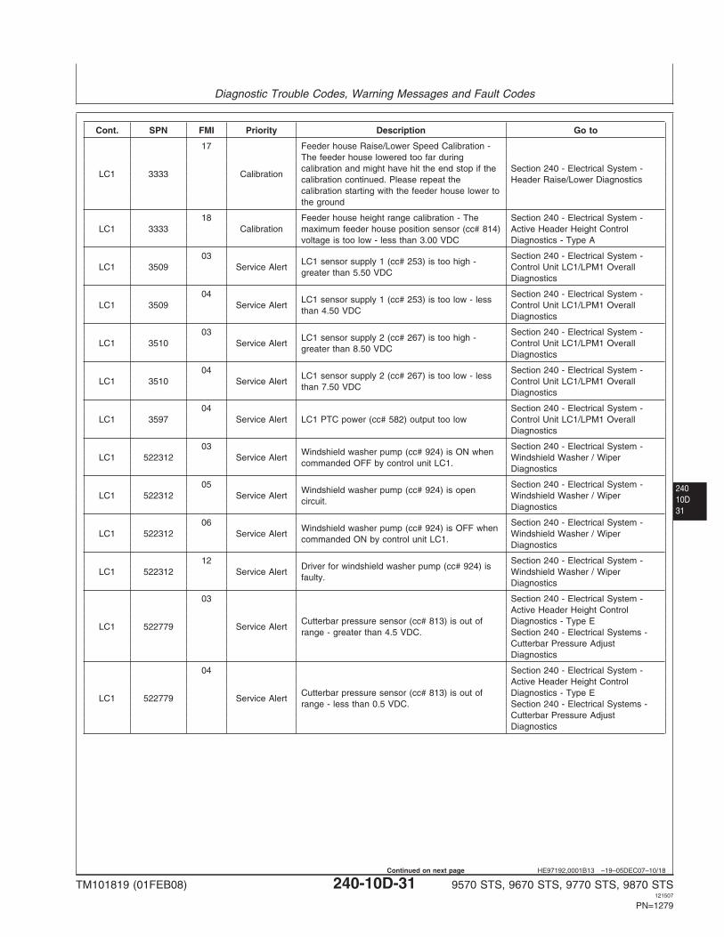
Diagnostic Trouble Codes, Warning Messages and Fault Codes
24010D31
HE97192,0001B13 –19–05DEC07–10/18
Cont. SPN FMI Priority Description Go to
17 Feeder house Raise/Lower Speed Calibration -The feeder house lowered too far duringcalibration and might have hit the end stop if the Section 240 - Electrical System -
LC1 3333 Calibrationcalibration continued. Please repeat the Header Raise/Lower Diagnosticscalibration starting with the feeder house lower tothe ground
18 Feeder house height range calibration - The Section 240 - Electrical System -LC1 3333 Calibration maximum feeder house position sensor (cc# 814) Active Header Height Control
voltage is too low - less than 3.00 VDC Diagnostics - Type A
03 Section 240 - Electrical System -LC1 sensor supply 1 (cc# 253) is too high -
LC1 3509 Service Alert Control Unit LC1/LPM1 Overallgreater than 5.50 VDC
Diagnostics
04 Section 240 - Electrical System -LC1 sensor supply 1 (cc# 253) is too low - less
LC1 3509 Service Alert Control Unit LC1/LPM1 Overallthan 4.50 VDC
Diagnostics
03 Section 240 - Electrical System -LC1 sensor supply 2 (cc# 267) is too high -
LC1 3510 Service Alert Control Unit LC1/LPM1 Overallgreater than 8.50 VDC
Diagnostics
04 Section 240 - Electrical System -LC1 sensor supply 2 (cc# 267) is too low - less
LC1 3510 Service Alert Control Unit LC1/LPM1 Overallthan 7.50 VDC
Diagnostics
04 Section 240 - Electrical System -LC1 3597 Service Alert LC1 PTC power (cc# 582) output too low Control Unit LC1/LPM1 Overall
Diagnostics
03 Section 240 - Electrical System -Windshield washer pump (cc# 924) is ON when
LC1 522312 Service Alert Windshield Washer / Wipercommanded OFF by control unit LC1.
Diagnostics
05 Section 240 - Electrical System -Windshield washer pump (cc# 924) is open
LC1 522312 Service Alert Windshield Washer / Wipercircuit.
Diagnostics
06 Section 240 - Electrical System -Windshield washer pump (cc# 924) is OFF when
LC1 522312 Service Alert Windshield Washer / Wipercommanded ON by control unit LC1.
Diagnostics
12 Section 240 - Electrical System -Driver for windshield washer pump (cc# 924) is
LC1 522312 Service Alert Windshield Washer / Wiperfaulty.
Diagnostics
03 Section 240 - Electrical System -Active Header Height Control
Cutterbar pressure sensor (cc# 813) is out of Diagnostics - Type ELC1 522779 Service Alert
range - greater than 4.5 VDC. Section 240 - Electrical Systems -Cutterbar Pressure AdjustDiagnostics
04 Section 240 - Electrical System -Active Header Height Control
Cutterbar pressure sensor (cc# 813) is out of Diagnostics - Type ELC1 522779 Service Alert
range - less than 0.5 VDC. Section 240 - Electrical Systems -Cutterbar Pressure AdjustDiagnostics
TM101819 (01FEB08) 240-10D-31 9570 STS, 9670 STS, 9770 STS, 9870 STS121507
PN=1279
Continued on next page
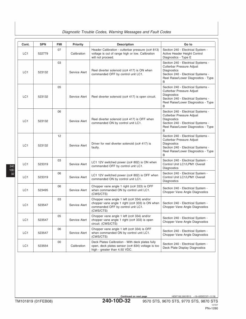
Diagnostic Trouble Codes, Warning Messages and Fault Codes
24010D
32
HE97192,0001B13 –19–05DEC07–11/18
Cont. SPN FMI Priority Description Go to
07 Header Calibration - cutterbar pressure (cc# 813) Section 240 - Electrical System -LC1 522779 Calibration voltage is out of range high or low. Calibration Active Header Height Control
will not proceed. Diagnostics - Type E
03 Section 240 - Electrical Systems -Cutterbar Pressure Adjust
Reel diverter solenoid (cc# 417) is ON when DiagnosticsLC1 523132 Service Alert
commanded OFF by control unit LC1. Section 240 - Electrical Systems -Reel Raise/Lower Diagnostics - TypeB
05 Section 240 - Electrical Systems -Cutterbar Pressure AdjustDiagnostics
LC1 523132 Service Alert Reel diverter solenoid (cc# 417) is open circuit.Section 240 - Electrical Systems -Reel Raise/Lower Diagnostics - TypeB
06 Section 240 - Electrical Systems -Cutterbar Pressure Adjust
Reel diverter solenoid (cc# 417) is OFF when DiagnosticsLC1 523132 Service Alert
commanded ON by control unit LC1. Section 240 - Electrical Systems -Reel Raise/Lower Diagnostics - TypeB
12 Section 240 - Electrical Systems -Cutterbar Pressure Adjust
Driver for reel diverter solenoid (cc# 417) is DiagnosticsLC1 523132 Service Alert
faulty. Section 240 - Electrical Systems -Reel Raise/Lower Diagnostics - TypeB
03 Section 240 - Electrical System -LC1 12V switched power (cc# 802) is ON when
LC1 523319 Service Alert Control Unit LC1/LPM1 Overallcommanded OFF by control unit LC1.
Diagnostics
06 Section 240 - Electrical System -LC1 12V switched power (cc# 802) is OFF when
LC1 523319 Service Alert Control Unit LC1/LPM1 Overallcommanded ON by control unit LC1.
Diagnostics
06 Chopper vane angle 1 right (cc# 333) is OFFSection 240 - Electrical System -
LC1 523495 Service Alert when commanded ON by control unit LC1.Chopper Vane Angle Diagnostics
(CWS/CTS)
03 Chopper vane angle 1 left (cc# 334) and/orchopper vane angle 1 right (cc# 333) is ON when Section 240 - Electrical System -
LC1 523547 Service Alertcommanded OFF by control unit LC1. Chopper Vane Angle Diagnostics(CWS/CTS)
05 Chopper vane angle 1 left (cc# 334) and/orSection 240 - Electrical System -
LC1 523547 Service Alert chopper vane angle 1 right (cc# 333) is openChopper Vane Angle Diagnostics
circuit. (CWS/CTS)
06 Chopper vane angle 1 left (cc# 334) is OFFSection 240 - Electrical System -
LC1 523547 Service Alert when commanded ON by control unit LC1.Chopper Vane Angle Diagnostics
(CWS/CTS)
00 Deck Plates Calibration - With deck plates fullySection 240 - Electrical System -
LC1 523554 Calibration open, deck plates sensor (cc# 834) voltage is tooDeck Plate Display Diagnostics
high - greater than 4.50 VDC.
TM101819 (01FEB08) 240-10D-32 9570 STS, 9670 STS, 9770 STS, 9870 STS121507
PN=1280
Continued on next page
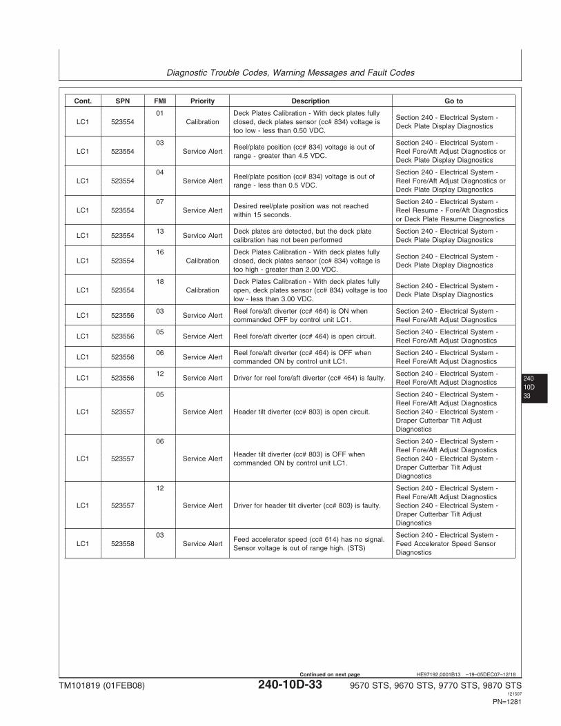
Diagnostic Trouble Codes, Warning Messages and Fault Codes
24010D33
HE97192,0001B13 –19–05DEC07–12/18
Cont. SPN FMI Priority Description Go to
01 Deck Plates Calibration - With deck plates fullySection 240 - Electrical System -
LC1 523554 Calibration closed, deck plates sensor (cc# 834) voltage isDeck Plate Display Diagnostics
too low - less than 0.50 VDC.
03 Section 240 - Electrical System -Reel/plate position (cc# 834) voltage is out of
LC1 523554 Service Alert Reel Fore/Aft Adjust Diagnostics orrange - greater than 4.5 VDC.
Deck Plate Display Diagnostics
04 Section 240 - Electrical System -Reel/plate position (cc# 834) voltage is out of
LC1 523554 Service Alert Reel Fore/Aft Adjust Diagnostics orrange - less than 0.5 VDC.
Deck Plate Display Diagnostics
07 Section 240 - Electrical System -Desired reel/plate position was not reached
LC1 523554 Service Alert Reel Resume - Fore/Aft Diagnosticswithin 15 seconds.
or Deck Plate Resume Diagnostics
13 Deck plates are detected, but the deck plate Section 240 - Electrical System -LC1 523554 Service Alert
calibration has not been performed Deck Plate Display Diagnostics
16 Deck Plates Calibration - With deck plates fullySection 240 - Electrical System -
LC1 523554 Calibration closed, deck plates sensor (cc# 834) voltage isDeck Plate Display Diagnostics
too high - greater than 2.00 VDC.
18 Deck Plates Calibration - With deck plates fullySection 240 - Electrical System -
LC1 523554 Calibration open, deck plates sensor (cc# 834) voltage is tooDeck Plate Display Diagnostics
low - less than 3.00 VDC.
03 Reel fore/aft diverter (cc# 464) is ON when Section 240 - Electrical System -LC1 523556 Service Alert
commanded OFF by control unit LC1. Reel Fore/Aft Adjust Diagnostics
05 Section 240 - Electrical System -LC1 523556 Service Alert Reel fore/aft diverter (cc# 464) is open circuit.
Reel Fore/Aft Adjust Diagnostics
06 Reel fore/aft diverter (cc# 464) is OFF when Section 240 - Electrical System -LC1 523556 Service Alert
commanded ON by control unit LC1. Reel Fore/Aft Adjust Diagnostics
12 Section 240 - Electrical System -LC1 523556 Service Alert Driver for reel fore/aft diverter (cc# 464) is faulty.
Reel Fore/Aft Adjust Diagnostics
05 Section 240 - Electrical System -Reel Fore/Aft Adjust Diagnostics
LC1 523557 Service Alert Header tilt diverter (cc# 803) is open circuit. Section 240 - Electrical System -Draper Cutterbar Tilt AdjustDiagnostics
06 Section 240 - Electrical System -Reel Fore/Aft Adjust Diagnostics
Header tilt diverter (cc# 803) is OFF whenLC1 523557 Service Alert Section 240 - Electrical System -
commanded ON by control unit LC1.Draper Cutterbar Tilt AdjustDiagnostics
12 Section 240 - Electrical System -Reel Fore/Aft Adjust Diagnostics
LC1 523557 Service Alert Driver for header tilt diverter (cc# 803) is faulty. Section 240 - Electrical System -Draper Cutterbar Tilt AdjustDiagnostics
03 Section 240 - Electrical System -Feed accelerator speed (cc# 614) has no signal.
LC1 523558 Service Alert Feed Accelerator Speed SensorSensor voltage is out of range high. (STS)
Diagnostics
TM101819 (01FEB08) 240-10D-33 9570 STS, 9670 STS, 9770 STS, 9870 STS121507
PN=1281
Continued on next page
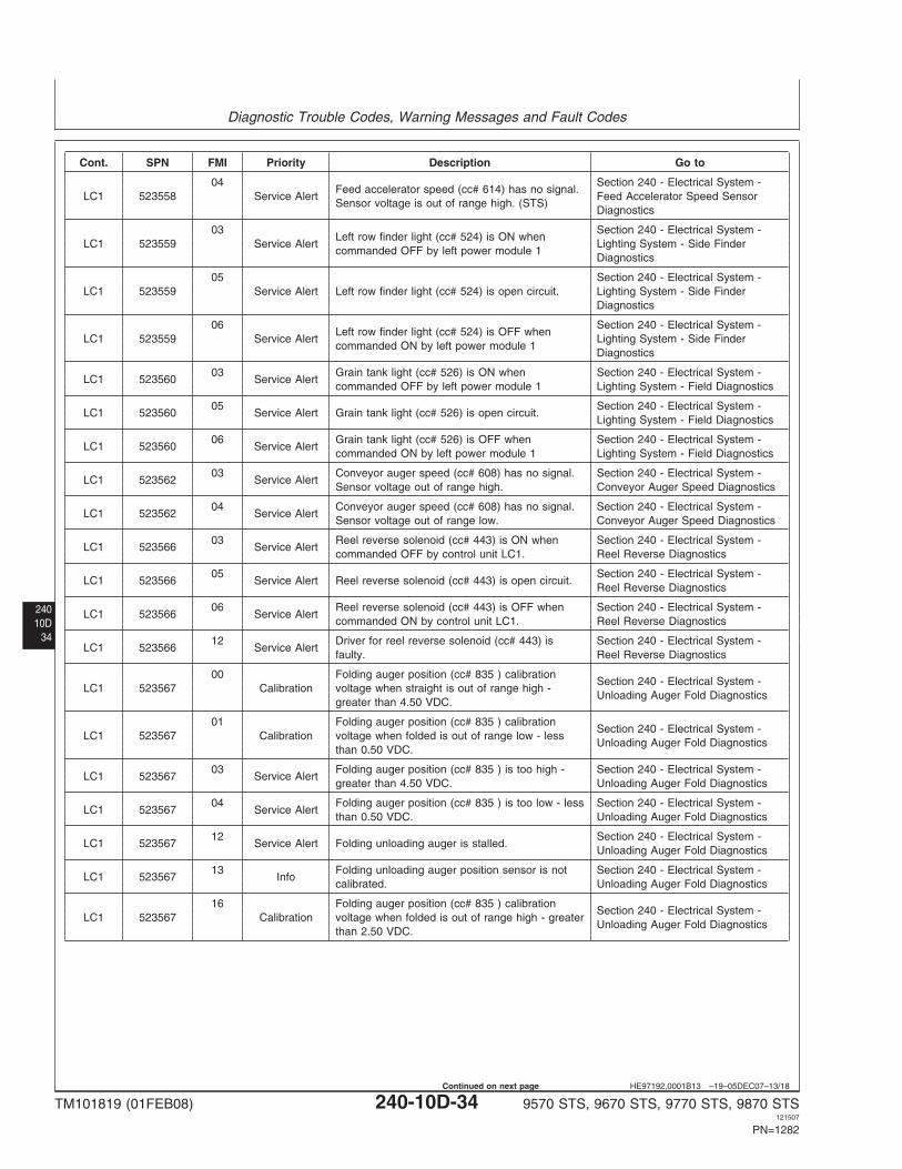
Diagnostic Trouble Codes, Warning Messages and Fault Codes
24010D
34
HE97192,0001B13 –19–05DEC07–13/18
Cont. SPN FMI Priority Description Go to
04 Section 240 - Electrical System -Feed accelerator speed (cc# 614) has no signal.
LC1 523558 Service Alert Feed Accelerator Speed SensorSensor voltage is out of range high. (STS)
Diagnostics
03 Section 240 - Electrical System -Left row finder light (cc# 524) is ON when
LC1 523559 Service Alert Lighting System - Side Findercommanded OFF by left power module 1
Diagnostics
05 Section 240 - Electrical System -LC1 523559 Service Alert Left row finder light (cc# 524) is open circuit. Lighting System - Side Finder
Diagnostics
06 Section 240 - Electrical System -Left row finder light (cc# 524) is OFF when
LC1 523559 Service Alert Lighting System - Side Findercommanded ON by left power module 1
Diagnostics
03 Grain tank light (cc# 526) is ON when Section 240 - Electrical System -LC1 523560 Service Alert
commanded OFF by left power module 1 Lighting System - Field Diagnostics
05 Section 240 - Electrical System -LC1 523560 Service Alert Grain tank light (cc# 526) is open circuit.
Lighting System - Field Diagnostics
06 Grain tank light (cc# 526) is OFF when Section 240 - Electrical System -LC1 523560 Service Alert
commanded ON by left power module 1 Lighting System - Field Diagnostics
03 Conveyor auger speed (cc# 608) has no signal. Section 240 - Electrical System -LC1 523562 Service Alert
Sensor voltage out of range high. Conveyor Auger Speed Diagnostics
04 Conveyor auger speed (cc# 608) has no signal. Section 240 - Electrical System -LC1 523562 Service Alert
Sensor voltage out of range low. Conveyor Auger Speed Diagnostics
03 Reel reverse solenoid (cc# 443) is ON when Section 240 - Electrical System -LC1 523566 Service Alert
commanded OFF by control unit LC1. Reel Reverse Diagnostics
05 Section 240 - Electrical System -LC1 523566 Service Alert Reel reverse solenoid (cc# 443) is open circuit.
Reel Reverse Diagnostics
06 Reel reverse solenoid (cc# 443) is OFF when Section 240 - Electrical System -LC1 523566 Service Alert
commanded ON by control unit LC1. Reel Reverse Diagnostics
12 Driver for reel reverse solenoid (cc# 443) is Section 240 - Electrical System -LC1 523566 Service Alert
faulty. Reel Reverse Diagnostics
00 Folding auger position (cc# 835 ) calibrationSection 240 - Electrical System -
LC1 523567 Calibration voltage when straight is out of range high -Unloading Auger Fold Diagnostics
greater than 4.50 VDC.
01 Folding auger position (cc# 835 ) calibrationSection 240 - Electrical System -
LC1 523567 Calibration voltage when folded is out of range low - lessUnloading Auger Fold Diagnostics
than 0.50 VDC.
03 Folding auger position (cc# 835 ) is too high - Section 240 - Electrical System -LC1 523567 Service Alert
greater than 4.50 VDC. Unloading Auger Fold Diagnostics
04 Folding auger position (cc# 835 ) is too low - less Section 240 - Electrical System -LC1 523567 Service Alert
than 0.50 VDC. Unloading Auger Fold Diagnostics
12 Section 240 - Electrical System -LC1 523567 Service Alert Folding unloading auger is stalled.
Unloading Auger Fold Diagnostics
13 Folding unloading auger position sensor is not Section 240 - Electrical System -LC1 523567 Info
calibrated. Unloading Auger Fold Diagnostics
16 Folding auger position (cc# 835 ) calibrationSection 240 - Electrical System -
LC1 523567 Calibration voltage when folded is out of range high - greaterUnloading Auger Fold Diagnostics
than 2.50 VDC.
TM101819 (01FEB08) 240-10D-34 9570 STS, 9670 STS, 9770 STS, 9870 STS121507
PN=1282
Continued on next page
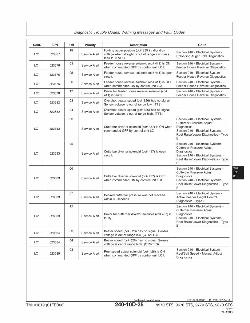
Diagnostic Trouble Codes, Warning Messages and Fault Codes
24010D35
HE97192,0001B13 –19–05DEC07–14/18
Cont. SPN FMI Priority Description Go to
18 Folding auger position (cc# 835 ) calibrationSection 240 - Electrical System -
LC1 523567 Service Alert voltage when straight is out of range low - lessUnloading Auger Fold Diagnostics
than 2.50 VDC.
03 Feeder house reverse solenoid (cc# 411) is ON Section 240 - Electrical System -LC1 523576 Service Alert
when commanded OFF by control unit LC1. Feeder House Reverse Diagnostics
05 Feeder house reverse solenoid (cc# 411) is open Section 240 - Electrical System -LC1 523576 Service Alert
circuit. Feeder House Reverse Diagnostics
06 Feeder house reverse solenoid (cc# 411) is OFF Section 240 - Electrical System -LC1 523576 Service Alert
when commanded ON by control unit LC1. Feeder House Reverse Diagnostics
12 Driver for feeder house reverse solenoid (cc# Section 240 - Electrical System -LC1 523576 Service Alert
411) is faulty. Feeder House Reverse Diagnostics
03 Overshot beater speed (cc# 626) has no signal.LC1 523582 Service Alert
Sensor voltage is out of range low. (TTS)
04 Overshot beater speed (cc# 626) has no signal.LC1 523582 Service Alert
Sensor voltage is out of range high. (TTS)
03 Section 240 - Electrical Systems -Cutterbar Pressure Adjust
Cutterbar diverter solenoid (cc# 457) is ON when DiagnosticsLC1 523583 Service Alert
commanded OFF by control unit LC1. Section 240 - Electrical Systems -Reel Raise/Lower Diagnostics - TypeB
05 Section 240 - Electrical Systems -Cutterbar Pressure Adjust
Cutterbar diverter solenoid (cc# 457) is open DiagnosticsLC1 523583 Service Alert
circuit. Section 240 - Electrical Systems -Reel Raise/Lower Diagnostics - TypeB
06 Section 240 - Electrical Systems -Cutterbar Pressure Adjust
Cutterbar diverter solenoid (cc# 457) is OFF DiagnosticsLC1 523583 Service Alert
when commanded ON by control unit LC1. Section 240 - Electrical Systems -Reel Raise/Lower Diagnostics - TypeB
07 Section 240 - Electrical System -Desired cutterbar pressure was not reached
LC1 523583 Service Alert Active Header Height Controlwithin 30 seconds.
Diagnostics - Type E
12 Section 240 - Electrical Systems -Cutterbar Pressure Adjust
Driver for cutterbar diverter solenoid (cc# 457) is DiagnosticsLC1 523583 Service Alert
faulty. Section 240 - Electrical Systems -Reel Raise/Lower Diagnostics - TypeB
03 Beater speed (cc# 628) has no signal. SensorLC1 523584 Service Alert
voltage is out of range low. (CTS/TTS)
04 Beater speed (cc# 628) has no signal. SensorLC1 523584 Service Alert
voltage is out of range high. (CTS/TTS)
03 Section 240 - Electrical System -Reel speed adjust solenoid (cc# 425) is ON
LC1 523585 Service Alert Reel/Belt Speed - Manual Adjustwhen commanded OFF by control unit LC1.
Diagnostics
TM101819 (01FEB08) 240-10D-35 9570 STS, 9670 STS, 9770 STS, 9870 STS121507
PN=1283
Continued on next page
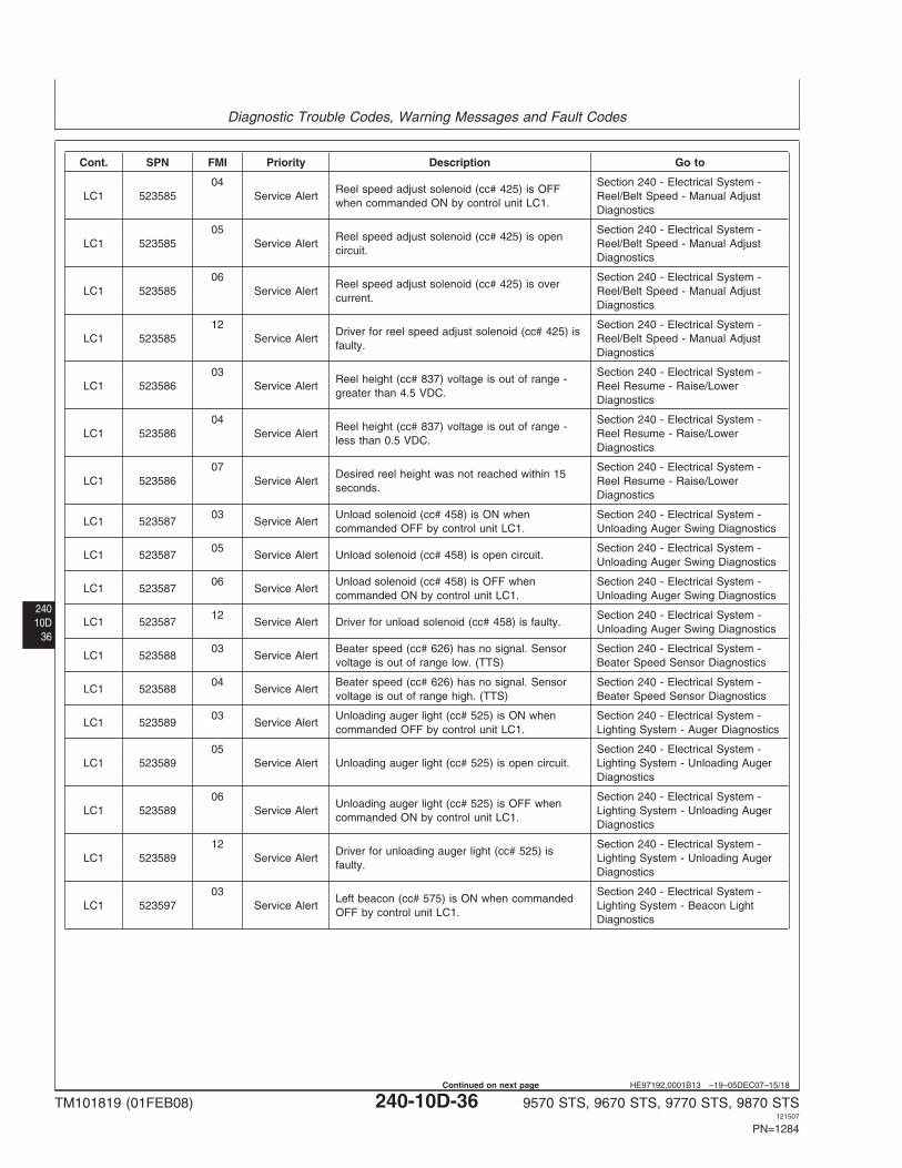
Diagnostic Trouble Codes, Warning Messages and Fault Codes
24010D
36
HE97192,0001B13 –19–05DEC07–15/18
Cont. SPN FMI Priority Description Go to
04 Section 240 - Electrical System -Reel speed adjust solenoid (cc# 425) is OFF
LC1 523585 Service Alert Reel/Belt Speed - Manual Adjustwhen commanded ON by control unit LC1.
Diagnostics
05 Section 240 - Electrical System -Reel speed adjust solenoid (cc# 425) is open
LC1 523585 Service Alert Reel/Belt Speed - Manual Adjustcircuit.
Diagnostics
06 Section 240 - Electrical System -Reel speed adjust solenoid (cc# 425) is over
LC1 523585 Service Alert Reel/Belt Speed - Manual Adjustcurrent.
Diagnostics
12 Section 240 - Electrical System -Driver for reel speed adjust solenoid (cc# 425) is
LC1 523585 Service Alert Reel/Belt Speed - Manual Adjustfaulty.
Diagnostics
03 Section 240 - Electrical System -Reel height (cc# 837) voltage is out of range -
LC1 523586 Service Alert Reel Resume - Raise/Lowergreater than 4.5 VDC.
Diagnostics
04 Section 240 - Electrical System -Reel height (cc# 837) voltage is out of range -
LC1 523586 Service Alert Reel Resume - Raise/Lowerless than 0.5 VDC.
Diagnostics
07 Section 240 - Electrical System -Desired reel height was not reached within 15
LC1 523586 Service Alert Reel Resume - Raise/Lowerseconds.
Diagnostics
03 Unload solenoid (cc# 458) is ON when Section 240 - Electrical System -LC1 523587 Service Alert
commanded OFF by control unit LC1. Unloading Auger Swing Diagnostics
05 Section 240 - Electrical System -LC1 523587 Service Alert Unload solenoid (cc# 458) is open circuit.
Unloading Auger Swing Diagnostics
06 Unload solenoid (cc# 458) is OFF when Section 240 - Electrical System -LC1 523587 Service Alert
commanded ON by control unit LC1. Unloading Auger Swing Diagnostics
12 Section 240 - Electrical System -LC1 523587 Service Alert Driver for unload solenoid (cc# 458) is faulty.
Unloading Auger Swing Diagnostics
03 Beater speed (cc# 626) has no signal. Sensor Section 240 - Electrical System -LC1 523588 Service Alert
voltage is out of range low. (TTS) Beater Speed Sensor Diagnostics
04 Beater speed (cc# 626) has no signal. Sensor Section 240 - Electrical System -LC1 523588 Service Alert
voltage is out of range high. (TTS) Beater Speed Sensor Diagnostics
03 Unloading auger light (cc# 525) is ON when Section 240 - Electrical System -LC1 523589 Service Alert
commanded OFF by control unit LC1. Lighting System - Auger Diagnostics
05 Section 240 - Electrical System -LC1 523589 Service Alert Unloading auger light (cc# 525) is open circuit. Lighting System - Unloading Auger
Diagnostics
06 Section 240 - Electrical System -Unloading auger light (cc# 525) is OFF when
LC1 523589 Service Alert Lighting System - Unloading Augercommanded ON by control unit LC1.
Diagnostics
12 Section 240 - Electrical System -Driver for unloading auger light (cc# 525) is
LC1 523589 Service Alert Lighting System - Unloading Augerfaulty.
Diagnostics
03 Section 240 - Electrical System -Left beacon (cc# 575) is ON when commanded
LC1 523597 Service Alert Lighting System - Beacon LightOFF by control unit LC1.
Diagnostics
TM101819 (01FEB08) 240-10D-36 9570 STS, 9670 STS, 9770 STS, 9870 STS121507
PN=1284
Continued on next page
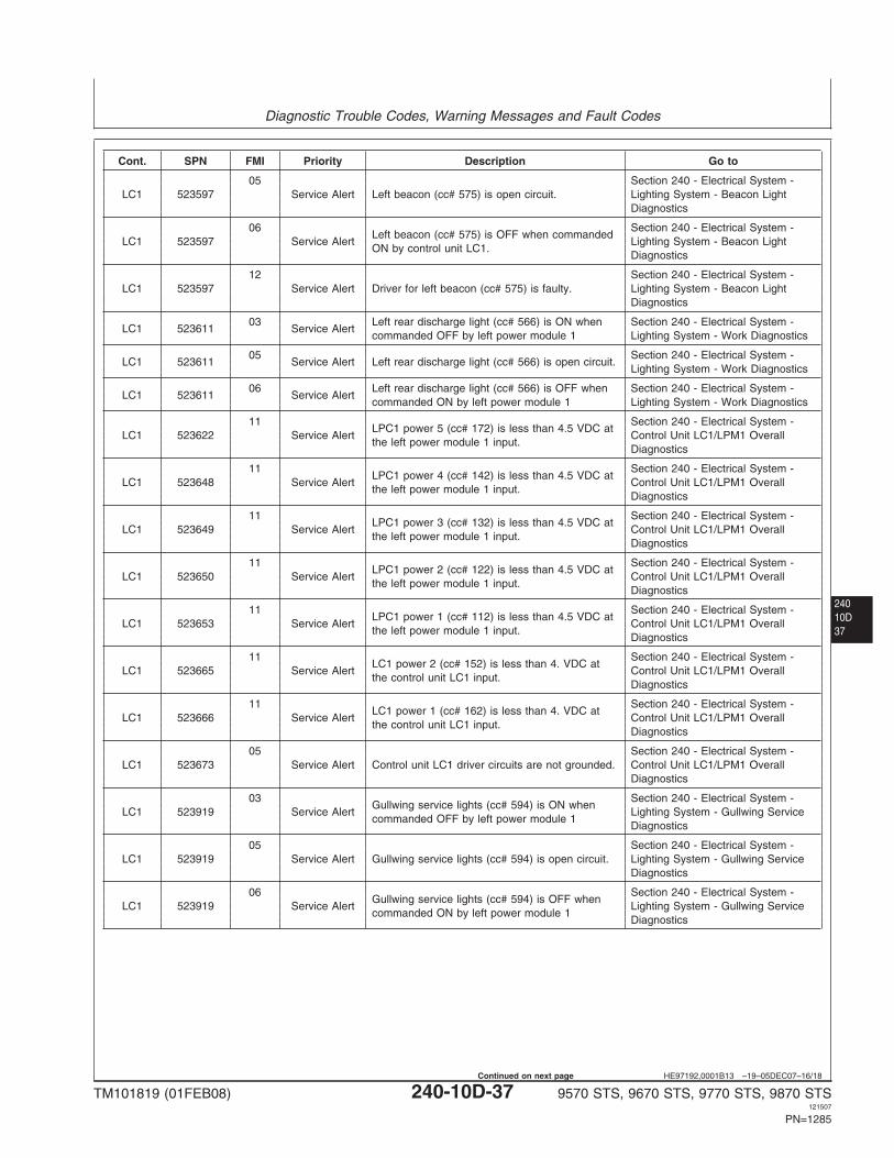
Diagnostic Trouble Codes, Warning Messages and Fault Codes
24010D37
HE97192,0001B13 –19–05DEC07–16/18
Cont. SPN FMI Priority Description Go to
05 Section 240 - Electrical System -LC1 523597 Service Alert Left beacon (cc# 575) is open circuit. Lighting System - Beacon Light
Diagnostics
06 Section 240 - Electrical System -Left beacon (cc# 575) is OFF when commanded
LC1 523597 Service Alert Lighting System - Beacon LightON by control unit LC1.
Diagnostics
12 Section 240 - Electrical System -LC1 523597 Service Alert Driver for left beacon (cc# 575) is faulty. Lighting System - Beacon Light
Diagnostics
03 Left rear discharge light (cc# 566) is ON when Section 240 - Electrical System -LC1 523611 Service Alert
commanded OFF by left power module 1 Lighting System - Work Diagnostics
05 Section 240 - Electrical System -LC1 523611 Service Alert Left rear discharge light (cc# 566) is open circuit.
Lighting System - Work Diagnostics
06 Left rear discharge light (cc# 566) is OFF when Section 240 - Electrical System -LC1 523611 Service Alert
commanded ON by left power module 1 Lighting System - Work Diagnostics
11 Section 240 - Electrical System -LPC1 power 5 (cc# 172) is less than 4.5 VDC at
LC1 523622 Service Alert Control Unit LC1/LPM1 Overallthe left power module 1 input.
Diagnostics
11 Section 240 - Electrical System -LPC1 power 4 (cc# 142) is less than 4.5 VDC at
LC1 523648 Service Alert Control Unit LC1/LPM1 Overallthe left power module 1 input.
Diagnostics
11 Section 240 - Electrical System -LPC1 power 3 (cc# 132) is less than 4.5 VDC at
LC1 523649 Service Alert Control Unit LC1/LPM1 Overallthe left power module 1 input.
Diagnostics
11 Section 240 - Electrical System -LPC1 power 2 (cc# 122) is less than 4.5 VDC at
LC1 523650 Service Alert Control Unit LC1/LPM1 Overallthe left power module 1 input.
Diagnostics
11 Section 240 - Electrical System -LPC1 power 1 (cc# 112) is less than 4.5 VDC at
LC1 523653 Service Alert Control Unit LC1/LPM1 Overallthe left power module 1 input.
Diagnostics
11 Section 240 - Electrical System -LC1 power 2 (cc# 152) is less than 4. VDC at
LC1 523665 Service Alert Control Unit LC1/LPM1 Overallthe control unit LC1 input.
Diagnostics
11 Section 240 - Electrical System -LC1 power 1 (cc# 162) is less than 4. VDC at
LC1 523666 Service Alert Control Unit LC1/LPM1 Overallthe control unit LC1 input.
Diagnostics
05 Section 240 - Electrical System -LC1 523673 Service Alert Control unit LC1 driver circuits are not grounded. Control Unit LC1/LPM1 Overall
Diagnostics
03 Section 240 - Electrical System -Gullwing service lights (cc# 594) is ON when
LC1 523919 Service Alert Lighting System - Gullwing Servicecommanded OFF by left power module 1
Diagnostics
05 Section 240 - Electrical System -LC1 523919 Service Alert Gullwing service lights (cc# 594) is open circuit. Lighting System - Gullwing Service
Diagnostics
06 Section 240 - Electrical System -Gullwing service lights (cc# 594) is OFF when
LC1 523919 Service Alert Lighting System - Gullwing Servicecommanded ON by left power module 1
Diagnostics
TM101819 (01FEB08) 240-10D-37 9570 STS, 9670 STS, 9770 STS, 9870 STS121507
PN=1285
Continued on next page
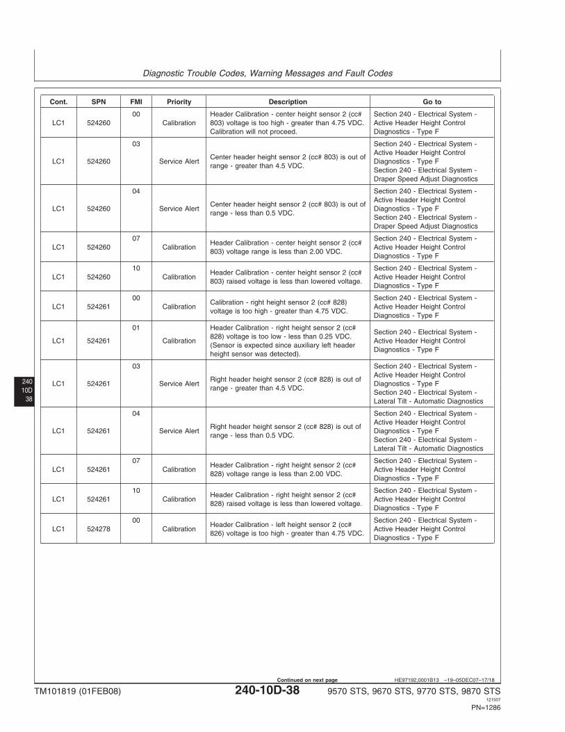
Diagnostic Trouble Codes, Warning Messages and Fault Codes
24010D
38
HE97192,0001B13 –19–05DEC07–17/18
Cont. SPN FMI Priority Description Go to
00 Header Calibration - center height sensor 2 (cc# Section 240 - Electrical System -LC1 524260 Calibration 803) voltage is too high - greater than 4.75 VDC. Active Header Height Control
Calibration will not proceed. Diagnostics - Type F
03 Section 240 - Electrical System -Active Header Height Control
Center header height sensor 2 (cc# 803) is out ofLC1 524260 Service Alert Diagnostics - Type F
range - greater than 4.5 VDC.Section 240 - Electrical System -Draper Speed Adjust Diagnostics
04 Section 240 - Electrical System -Active Header Height Control
Center header height sensor 2 (cc# 803) is out ofLC1 524260 Service Alert Diagnostics - Type F
range - less than 0.5 VDC.Section 240 - Electrical System -Draper Speed Adjust Diagnostics
07 Section 240 - Electrical System -Header Calibration - center height sensor 2 (cc#
LC1 524260 Calibration Active Header Height Control803) voltage range is less than 2.00 VDC.
Diagnostics - Type F
10 Section 240 - Electrical System -Header Calibration - center height sensor 2 (cc#
LC1 524260 Calibration Active Header Height Control803) raised voltage is less than lowered voltage.
Diagnostics - Type F
00 Section 240 - Electrical System -Calibration - right height sensor 2 (cc# 828)
LC1 524261 Calibration Active Header Height Controlvoltage is too high - greater than 4.75 VDC.
Diagnostics - Type F
01 Header Calibration - right height sensor 2 (cc#Section 240 - Electrical System -
828) voltage is too low - less than 0.25 VDC.LC1 524261 Calibration Active Header Height Control
(Sensor is expected since auxiliary left headerDiagnostics - Type F
height sensor was detected).
03 Section 240 - Electrical System -Active Header Height Control
Right header height sensor 2 (cc# 828) is out ofLC1 524261 Service Alert Diagnostics - Type F
range - greater than 4.5 VDC.Section 240 - Electrical System -Lateral Tilt - Automatic Diagnostics
04 Section 240 - Electrical System -Active Header Height Control
Right header height sensor 2 (cc# 828) is out ofLC1 524261 Service Alert Diagnostics - Type F
range - less than 0.5 VDC.Section 240 - Electrical System -Lateral Tilt - Automatic Diagnostics
07 Section 240 - Electrical System -Header Calibration - right height sensor 2 (cc#
LC1 524261 Calibration Active Header Height Control828) voltage range is less than 2.00 VDC.
Diagnostics - Type F
10 Section 240 - Electrical System -Header Calibration - right height sensor 2 (cc#
LC1 524261 Calibration Active Header Height Control828) raised voltage is less than lowered voltage.
Diagnostics - Type F
00 Section 240 - Electrical System -Header Calibration - left height sensor 2 (cc#
LC1 524278 Calibration Active Header Height Control826) voltage is too high - greater than 4.75 VDC.
Diagnostics - Type F
TM101819 (01FEB08) 240-10D-38 9570 STS, 9670 STS, 9770 STS, 9870 STS121507
PN=1286
Continued on next page
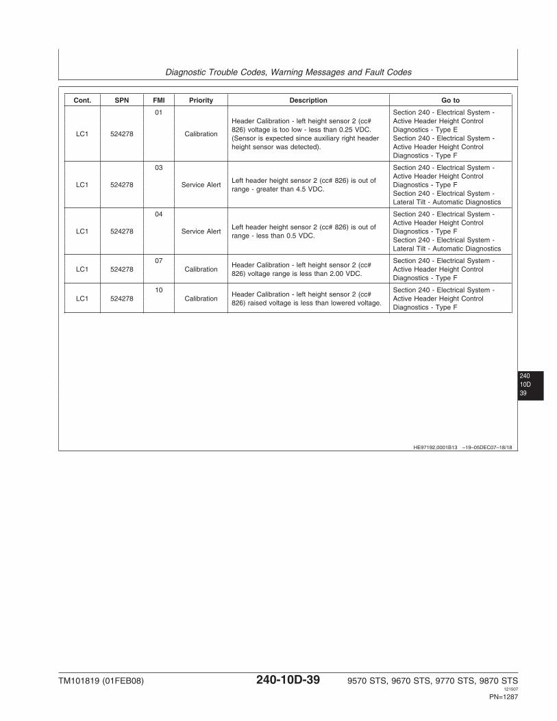
Diagnostic Trouble Codes, Warning Messages and Fault Codes
24010D39
HE97192,0001B13 –19–05DEC07–18/18
Cont. SPN FMI Priority Description Go to
01 Section 240 - Electrical System -Header Calibration - left height sensor 2 (cc# Active Header Height Control826) voltage is too low - less than 0.25 VDC. Diagnostics - Type E
LC1 524278 Calibration(Sensor is expected since auxiliary right header Section 240 - Electrical System -height sensor was detected). Active Header Height Control
Diagnostics - Type F
03 Section 240 - Electrical System -Active Header Height Control
Left header height sensor 2 (cc# 826) is out ofLC1 524278 Service Alert Diagnostics - Type F
range - greater than 4.5 VDC.Section 240 - Electrical System -Lateral Tilt - Automatic Diagnostics
04 Section 240 - Electrical System -Active Header Height Control
Left header height sensor 2 (cc# 826) is out ofLC1 524278 Service Alert Diagnostics - Type F
range - less than 0.5 VDC.Section 240 - Electrical System -Lateral Tilt - Automatic Diagnostics
07 Section 240 - Electrical System -Header Calibration - left height sensor 2 (cc#
LC1 524278 Calibration Active Header Height Control826) voltage range is less than 2.00 VDC.
Diagnostics - Type F
10 Section 240 - Electrical System -Header Calibration - left height sensor 2 (cc#
LC1 524278 Calibration Active Header Height Control826) raised voltage is less than lowered voltage.
Diagnostics - Type F
TM101819 (01FEB08) 240-10D-39 9570 STS, 9670 STS, 9770 STS, 9870 STS121507
PN=1287
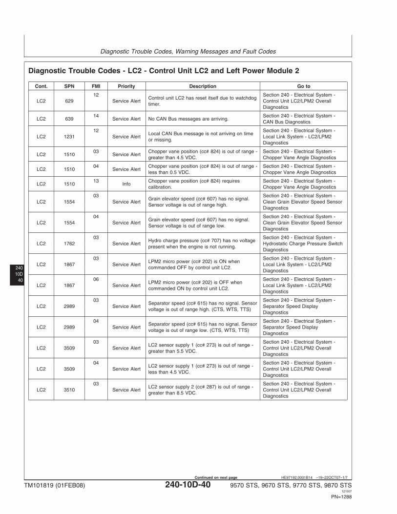
Diagnostic Trouble Codes, Warning Messages and Fault Codes
24010D
40
HE97192,0001B14 –19–22OCT07–1/7
Diagnostic Trouble Codes - LC2 - Control Unit LC2 and Left Power Module 2
Cont. SPN FMI Priority Description Go to
12 Section 240 - Electrical System -Control unit LC2 has reset itself due to watchdog
LC2 629 Service Alert Control Unit LC2/LPM2 Overalltimer.
Diagnostics
14 Section 240 - Electrical System -LC2 639 Service Alert No CAN Bus messages are arriving.
CAN Bus Diagnostics
12 Section 240 - Electrical System -Local CAN Bus message is not arriving on time
LC2 1231 Service Alert Local Link System - LC2/LPM2or missing.
Diagnostics
03 Chopper vane position (cc# 824) is out of range - Section 240 - Electrical System -LC2 1510 Service Alert
greater than 4.5 VDC. Chopper Vane Angle Diagnostics
04 Chopper vane position (cc# 824) is out of range - Section 240 - Electrical System -LC2 1510 Service Alert
less than 0.5 VDC. Chopper Vane Angle Diagnostics
13 Chopper vane position (cc# 824) requires Section 240 - Electrical System -LC2 1510 Info
calibration. Chopper Vane Angle Diagnostics
03 Section 240 - Electrical System -Grain elevator speed (cc# 607) has no signal.
LC2 1554 Service Alert Clean Grain Elevator Speed SensorSensor voltage is out of range high.
Diagnostics
04 Section 240 - Electrical System -Grain elevator speed (cc# 607) has no signal.
LC2 1554 Service Alert Clean Grain Elevator Speed SensorSensor voltage is out of range low.
Diagnostics
03 Section 240 - Electrical System -Hydro charge pressure (cc# 707) has no voltage
LC2 1762 Service Alert Hydrostatic Charge Pressure Switchpresent when the engine is not running.
Diagnostics
03 Section 240 - Electrical System -LPM2 micro power (cc# 202) is ON when
LC2 1867 Service Alert Local Link System - LC2/LPM2commanded OFF by control unit LC2.
Diagnostics
06 Section 240 - Electrical System -LPM2 micro power (cc# 202) is OFF when
LC2 1867 Service Alert Local Link System - LC2/LPM2commanded ON by control unit LC2.
Diagnostics
03 Section 240 - Electrical System -Separator speed (cc# 615) has no signal. Sensor
LC2 2989 Service Alert Separator Speed Displayvoltage is out of range high. (CTS, WTS, TTS)
Diagnostics
04 Section 240 - Electrical System -Separator speed (cc# 615) has no signal. Sensor
LC2 2989 Service Alert Separator Speed Displayvoltage is out of range low. (CTS, WTS, TTS)
Diagnostics
03 Section 240 - Electrical System -LC2 sensor supply 1 (cc# 273) is out of range -
LC2 3509 Service Alert Control Unit LC2/LPM2 Overallgreater than 5.5 VDC.
Diagnostics
04 Section 240 - Electrical System -LC2 sensor supply 1 (cc# 273) is out of range -
LC2 3509 Service Alert Control Unit LC2/LPM2 Overallless than 4.5 VDC.
Diagnostics
03 Section 240 - Electrical System -LC2 sensor supply 2 (cc# 287) is out of range -
LC2 3510 Service Alert Control Unit LC2/LPM2 Overallgreater than 8.5 VDC.
Diagnostics
TM101819 (01FEB08) 240-10D-40 9570 STS, 9670 STS, 9770 STS, 9870 STS121507
PN=1288
Continued on next page
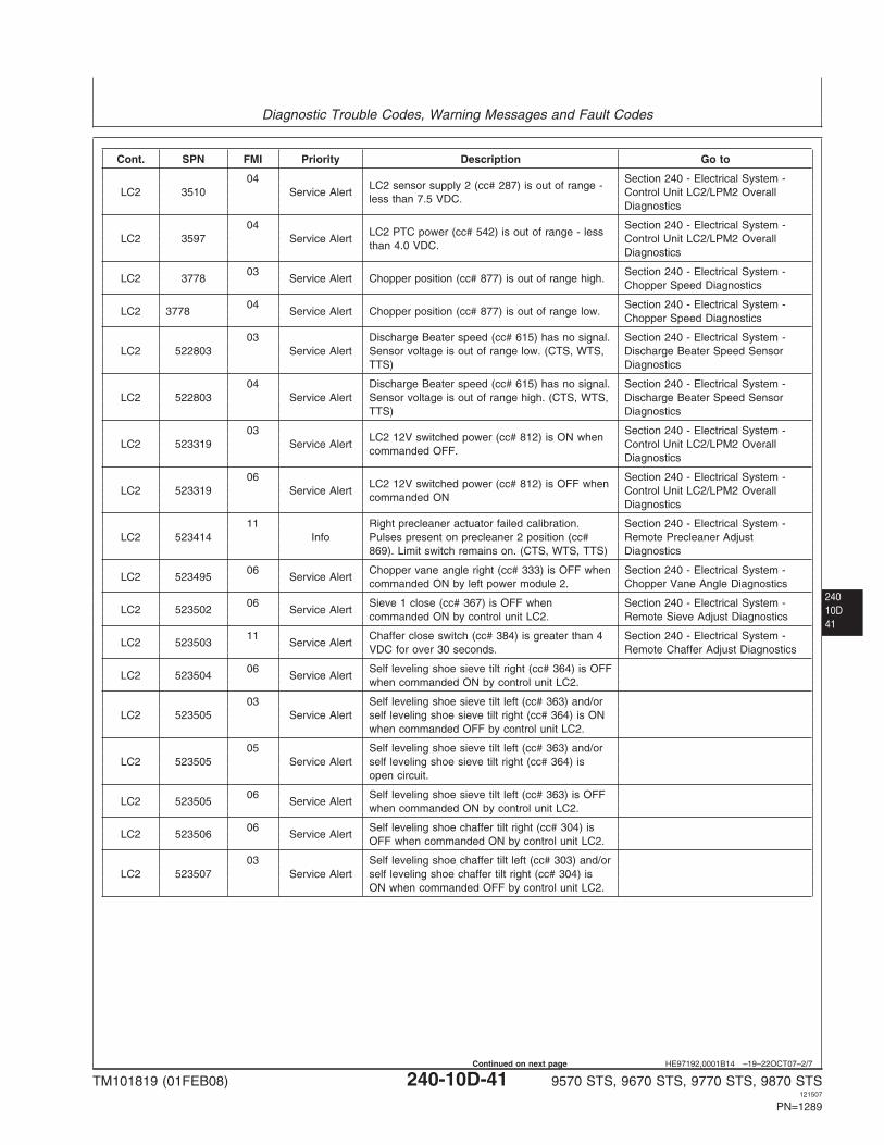
Diagnostic Trouble Codes, Warning Messages and Fault Codes
24010D41
HE97192,0001B14 –19–22OCT07–2/7
Cont. SPN FMI Priority Description Go to
04 Section 240 - Electrical System -LC2 sensor supply 2 (cc# 287) is out of range -
LC2 3510 Service Alert Control Unit LC2/LPM2 Overallless than 7.5 VDC.
Diagnostics
04 Section 240 - Electrical System -LC2 PTC power (cc# 542) is out of range - less
LC2 3597 Service Alert Control Unit LC2/LPM2 Overallthan 4.0 VDC.
Diagnostics
03 Section 240 - Electrical System -LC2 3778 Service Alert Chopper position (cc# 877) is out of range high.
Chopper Speed Diagnostics
04 Section 240 - Electrical System -LC2 3778 Service Alert Chopper position (cc# 877) is out of range low.
Chopper Speed Diagnostics
03 Discharge Beater speed (cc# 615) has no signal. Section 240 - Electrical System -LC2 522803 Service Alert Sensor voltage is out of range low. (CTS, WTS, Discharge Beater Speed Sensor
TTS) Diagnostics
04 Discharge Beater speed (cc# 615) has no signal. Section 240 - Electrical System -LC2 522803 Service Alert Sensor voltage is out of range high. (CTS, WTS, Discharge Beater Speed Sensor
TTS) Diagnostics
03 Section 240 - Electrical System -LC2 12V switched power (cc# 812) is ON when
LC2 523319 Service Alert Control Unit LC2/LPM2 Overallcommanded OFF.
Diagnostics
06 Section 240 - Electrical System -LC2 12V switched power (cc# 812) is OFF when
LC2 523319 Service Alert Control Unit LC2/LPM2 Overallcommanded ON
Diagnostics
11 Right precleaner actuator failed calibration. Section 240 - Electrical System -LC2 523414 Info Pulses present on precleaner 2 position (cc# Remote Precleaner Adjust
869). Limit switch remains on. (CTS, WTS, TTS) Diagnostics
06 Chopper vane angle right (cc# 333) is OFF when Section 240 - Electrical System -LC2 523495 Service Alert
commanded ON by left power module 2. Chopper Vane Angle Diagnostics
06 Sieve 1 close (cc# 367) is OFF when Section 240 - Electrical System -LC2 523502 Service Alert
commanded ON by control unit LC2. Remote Sieve Adjust Diagnostics
11 Chaffer close switch (cc# 384) is greater than 4 Section 240 - Electrical System -LC2 523503 Service Alert
VDC for over 30 seconds. Remote Chaffer Adjust Diagnostics
06 Self leveling shoe sieve tilt right (cc# 364) is OFFLC2 523504 Service Alert
when commanded ON by control unit LC2.
03 Self leveling shoe sieve tilt left (cc# 363) and/orLC2 523505 Service Alert self leveling shoe sieve tilt right (cc# 364) is ON
when commanded OFF by control unit LC2.
05 Self leveling shoe sieve tilt left (cc# 363) and/orLC2 523505 Service Alert self leveling shoe sieve tilt right (cc# 364) is
open circuit.
06 Self leveling shoe sieve tilt left (cc# 363) is OFFLC2 523505 Service Alert
when commanded ON by control unit LC2.
06 Self leveling shoe chaffer tilt right (cc# 304) isLC2 523506 Service Alert
OFF when commanded ON by control unit LC2.
03 Self leveling shoe chaffer tilt left (cc# 303) and/orLC2 523507 Service Alert self leveling shoe chaffer tilt right (cc# 304) is
ON when commanded OFF by control unit LC2.
TM101819 (01FEB08) 240-10D-41 9570 STS, 9670 STS, 9770 STS, 9870 STS121507
PN=1289
Continued on next page
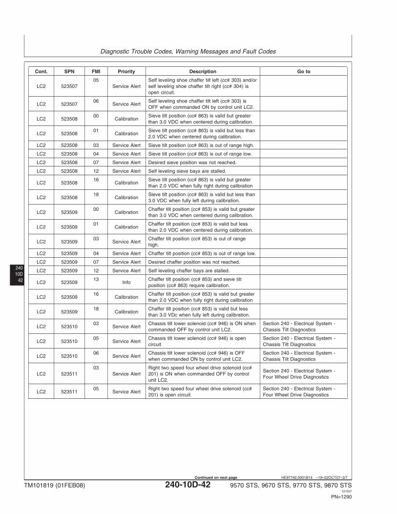
Diagnostic Trouble Codes, Warning Messages and Fault Codes
24010D
42
HE97192,0001B14 –19–22OCT07–3/7
Cont. SPN FMI Priority Description Go to
05 Self leveling shoe chaffer tilt left (cc# 303) and/orLC2 523507 Service Alert self leveling shoe chaffer tilt right (cc# 304) is
open circuit.
06 Self leveling shoe chaffer tilt left (cc# 303) isLC2 523507 Service Alert
OFF when commanded ON by control unit LC2.
00 Sieve tilt position (cc# 863) is valid but greaterLC2 523508 Calibration
than 3.0 VDC when centered during calibration.
01 Sieve tilt position (cc# 863) is valid but less thanLC2 523508 Calibration
2.0 VDC when centered during calibration.
LC2 523508 03 Service Alert Sieve tilt position (cc# 863) is out of range high.
LC2 523508 04 Service Alert Sieve tilt position (cc# 863) is out of range low.
LC2 523508 07 Service Alert Desired sieve position was not reached.
LC2 523508 12 Service Alert Self leveling sieve bays are stalled.
16 Sieve tilt position (cc# 863) is valid but greaterLC2 523508 Calibration
than 2.0 VDC when fully right during calibration
18 Sieve tilt position (cc# 863) is valid but less thanLC2 523508 Calibration
3.0 VDC when fully left during calibration.
00 Chaffer tilt position (cc# 853) is valid but greaterLC2 523509 Calibration
than 3.0 VDC when centered during calibration.
01 Chaffer tilt position (cc# 853) is valid but lessLC2 523509 Calibration
than 2.0 VDC when centered during calibration.
03 Chaffer tilt position (cc# 853) is out of rangeLC2 523509 Service Alert
high.
LC2 523509 04 Service Alert Chaffer tilt position (cc# 853) is out of range low.
LC2 523509 07 Service Alert Desired chaffer position was not reached.
LC2 523509 12 Service Alert Self leveling chaffer bays are stalled.
13 Chaffer tilt position (cc# 853) and sieve tiltLC2 523509 Info
position (cc# 863) require calibration.
16 Chaffer tilt position (cc# 853) is valid but greaterLC2 523509 Calibration
than 2.0 VDC when fully right during calibration
18 Chaffer tilt position (cc# 853) is valid but lessLC2 523509 Calibration
than 3.0 VDc when fully left during calibration.
03 Chassis tilt lower solenoid (cc# 946) is ON when Section 240 - Electrical System -LC2 523510 Service Alert
commanded OFF by control unit LC2. Chassis Tilt Diagnostics
05 Chassis tilt lower solenoid (cc# 946) is open Section 240 - Electrical System -LC2 523510 Service Alert
circuit Chassis Tilt Diagnostics
06 Chassis tilt lower solenoid (cc# 946) is OFF Section 240 - Electrical System -LC2 523510 Service Alert
when commanded ON by control unit LC2. Chassis Tilt Diagnostics
03 Right two speed four wheel drive solenoid (cc#Section 240 - Electrical System -
LC2 523511 Service Alert 201) is ON when commanded OFF by controlFour Wheel Drive Diagnostics
unit LC2.
05 Right two speed four wheel drive solenoid (cc# Section 240 - Electrical System -LC2 523511 Service Alert
201) is open circuit. Four Wheel Drive Diagnostics
TM101819 (01FEB08) 240-10D-42 9570 STS, 9670 STS, 9770 STS, 9870 STS121507
PN=1290
Continued on next page
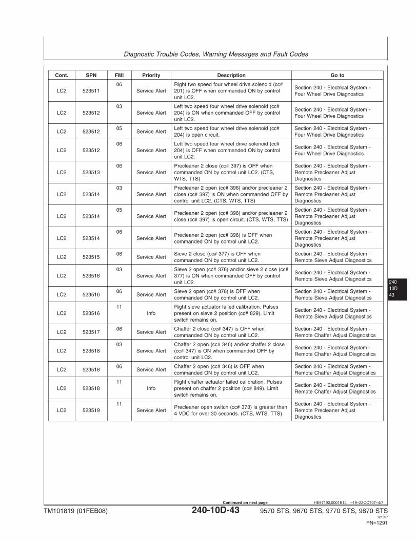
Diagnostic Trouble Codes, Warning Messages and Fault Codes
24010D43
HE97192,0001B14 –19–22OCT07–4/7
Cont. SPN FMI Priority Description Go to
06 Right two speed four wheel drive solenoid (cc#Section 240 - Electrical System -
LC2 523511 Service Alert 201) is OFF when commanded ON by controlFour Wheel Drive Diagnostics
unit LC2.
03 Left two speed four wheel drive solenoid (cc#Section 240 - Electrical System -
LC2 523512 Service Alert 204) is ON when commanded OFF by controlFour Wheel Drive Diagnostics
unit LC2.
05 Left two speed four wheel drive solenoid (cc# Section 240 - Electrical System -LC2 523512 Service Alert
204) is open circuit. Four Wheel Drive Diagnostics
06 Left two speed four wheel drive solenoid (cc#Section 240 - Electrical System -
LC2 523512 Service Alert 204) is OFF when commanded ON by controlFour Wheel Drive Diagnostics
unit LC2.
06 Precleaner 2 close (cc# 397) is OFF when Section 240 - Electrical System -LC2 523513 Service Alert commanded ON by control unit LC2. (CTS, Remote Precleaner Adjust
WTS, TTS) Diagnostics
03 Precleaner 2 open (cc# 396) and/or precleaner 2 Section 240 - Electrical System -LC2 523514 Service Alert close (cc# 397) is ON when commanded OFF by Remote Precleaner Adjust
control unit LC2. (CTS, WTS, TTS) Diagnostics
05 Section 240 - Electrical System -Precleaner 2 open (cc# 396) and/or precleaner 2
LC2 523514 Service Alert Remote Precleaner Adjustclose (cc# 397) is open circuit. (CTS, WTS, TTS)
Diagnostics
06 Section 240 - Electrical System -Precleaner 2 open (cc# 396) is OFF when
LC2 523514 Service Alert Remote Precleaner Adjustcommanded ON by control unit LC2.
Diagnostics
06 Sieve 2 close (cc# 377) is OFF when Section 240 - Electrical System -LC2 523515 Service Alert
commanded ON by control unit LC2. Remote Sieve Adjust Diagnostics
03 Sieve 2 open (cc# 376) and/or sieve 2 close (cc#Section 240 - Electrical System -
LC2 523516 Service Alert 377) is ON when commanded OFF by controlRemote Sieve Adjust Diagnostics
unit LC2.
06 Sieve 2 open (cc# 376) is OFF when Section 240 - Electrical System -LC2 523516 Service Alert
commanded ON by control unit LC2. Remote Sieve Adjust Diagnostics
11 Right sieve actuator failed calibration. PulsesSection 240 - Electrical System -
LC2 523516 Info present on sieve 2 position (cc# 829). LimitRemote Sieve Adjust Diagnostics
switch remains on.
06 Chaffer 2 close (cc# 347) is OFF when Section 240 - Electrical System -LC2 523517 Service Alert
commanded ON by control unit LC2. Remote Chaffer Adjust Diagnostics
03 Chaffer 2 open (cc# 346) and/or chaffer 2 closeSection 240 - Electrical System -
LC2 523518 Service Alert (cc# 347) is ON when commanded OFF byRemote Chaffer Adjust Diagnostics
control unit LC2.
06 Chaffer 2 open (cc# 346) is OFF when Section 240 - Electrical System -LC2 523518 Service Alert
commanded ON by control unit LC2. Remote Chaffer Adjust Diagnostics
11 Right chaffer actuator failed calibration. PulsesSection 240 - Electrical System -
LC2 523518 Info present on chaffer 2 position (cc# 849). LimitRemote Chaffer Adjust Diagnostics
switch remains on.
11 Section 240 - Electrical System -Precleaner open switch (cc# 373) is greater than
LC2 523519 Service Alert Remote Precleaner Adjust4 VDC for over 30 seconds. (CTS, WTS, TTS)
Diagnostics
TM101819 (01FEB08) 240-10D-43 9570 STS, 9670 STS, 9770 STS, 9870 STS121507
PN=1291
Continued on next page
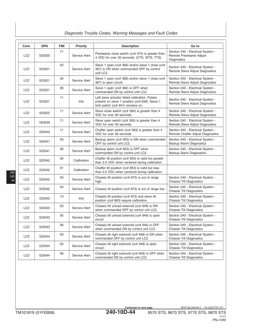
Diagnostic Trouble Codes, Warning Messages and Fault Codes
24010D
44
HE97192,0001B14 –19–22OCT07–5/7
Cont. SPN FMI Priority Description Go to
11 Section 240 - Electrical System -Precleaner close switch (cc# 374) is greater than
LC2 523520 Service Alert Remote Precleaner Adjust4 VDC for over 30 seconds. (CTS, WTS, TTS)
Diagnostics
03 Sieve 1 open (cc# 366) and/or sieve 1 close (cc#Section 240 - Electrical System -
LC2 523521 Service Alert 367) is ON when commanded OFF by controlRemote Sieve Adjust Diagnostics
unit LC2.
05 Sieve 1 open (cc# 366) and/or sieve 1 close (cc# Section 240 - Electrical System -LC2 523521 Service Alert
367) is open circuit. Remote Sieve Adjust Diagnostics
06 Sieve 1 open (cc# 366) is OFF when Section 240 - Electrical System -LC2 523521 Service Alert
commanded ON by control unit LC2. Remote Sieve Adjust Diagnostics
11 Left sieve actuator failed calibration. PulsesSection 240 - Electrical System -
LC2 523521 Info present on sieve 1 position (cc# 839). Sieve 1Remote Sieve Adjust Diagnostics
limit switch (cc# 841) remains on.
11 Sieve close switch (cc# 394) is greater than 4 Section 240 - Electrical System -LC2 523522 Service Alert
VDC for over 30 seconds. Remote Sieve Adjust Diagnostics
11 Sieve open switch (cc# 393) is greater than 4 Section 240 - Electrical System -LC2 523539 Service Alert
VDC for over 30 seconds. Remote Sieve Adjust Diagnostics
11 Chaffer open switch (cc# 383) is greater than 4 Section 240 - Electrical System -LC2 523540 Service Alert
VDC for over 30 seconds. Remote Chaffer Adjust Diagnostics
03 Backup alarm (cc# 903) is ON when commanded Section 240 - Electrical System -LC2 523541 Service Alert
OFF by control unit LC2. Backup Alarm Diagnostics
06 Backup alarm (cc# 903) is OFF when Section 240 - Electrical System -LC2 523541 Service Alert
commanded ON by control unit LC2. Backup Alarm Diagnostics
00 Chaffer tilt position (cc# 853) is valid but greaterLC2 523542 Calibration
than 3.0 VDC when centered during calibration.
01 Chaffer tilt position (cc# 853) is valid but lessLC2 523542 Calibration
than 2.0 VDC when centered during calibration.
03 Chassis tilt position (cc# 873) is out of range Section 240 - Electrical System -LC2 523542 Service Alert
high. Chassis Tilt Diagnostics
04 Section 240 - Electrical System -LC2 523542 Service Alert Chassis tilt position (cc# 873) is out of range low.
Chassis Tilt Diagnostics
13 Chassis tilt position (cc# 873) and sieve tilt Section 240 - Electrical System -LC2 523542 Info
position (cc# 863) require calibration. Chassis Tilt Diagnostics
03 Chassis tilt unload solenoid (cc# 949) is ON Section 240 - Electrical System -LC2 523543 Service Alert
when commanded OFF by control unit LC2. Chassis Tilt Diagnostics
05 Chassis tilt unload solenoid (cc# 949) is open Section 240 - Electrical System -LC2 523543 Service Alert
circuit Chassis Tilt Diagnostics
06 Chassis tilt unload solenoid (cc# 949) is OFF Section 240 - Electrical System -LC2 523543 Service Alert
when commanded ON by control unit LC2. Chassis Tilt Diagnostics
03 Chassis tilt right solenoid (cc# 948) is ON when Section 240 - Electrical System -LC2 523544 Service Alert
commanded OFF by control unit LC2. Chassis Tilt Diagnostics
05 Chassis tilt right solenoid (cc# 948) is open Section 240 - Electrical System -LC2 523544 Service Alert
circuit. Chassis Tilt Diagnostics
06 Chassis tilt right solenoid (cc# 948) is OFF when Section 240 - Electrical System -LC2 523544 Service Alert
commanded ON by control unit LC2. Chassis Tilt Diagnostics
TM101819 (01FEB08) 240-10D-44 9570 STS, 9670 STS, 9770 STS, 9870 STS121507
PN=1292
Continued on next page
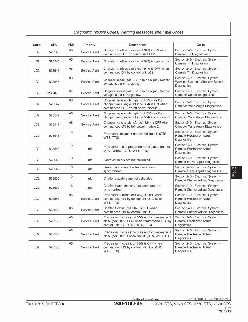
Diagnostic Trouble Codes, Warning Messages and Fault Codes
24010D45
HE97192,0001B14 –19–22OCT07–6/7
Cont. SPN FMI Priority Description Go to
03 Chassis tilt left solenoid (cc# 947) is ON when Section 240 - Electrical System -LC2 523545 Service Alert
commanded OFF by control unit LC2. Chassis Tilt Diagnostics
05 Section 240 - Electrical System -LC2 523545 Service Alert Chassis tilt left solenoid (cc# 947) is open circuit
Chassis Tilt Diagnostics
06 Chassis tilt left solenoid (cc# 947) is OFF when Section 240 - Electrical System -LC2 523545 Service Alert
commanded ON by control unit LC2. Chassis Tilt Diagnostics
03 Section 240 - Electrical System -Chopper speed (cc# 617) has no signal. Sensor
LC2 523546 Service Alert Warning System - Chopper Speedvoltage is out of range high.
Diagnostics
04 Chopper speed (cc# 617) has no signal. Sensor Section 240 - Electrical System -LC2 523546 Service Alert
voltage is out of range low. Chopper Speed Diagnostics
03 Chopper vane angle right (cc# 333) and/orSection 240 - Electrical System -
LC2 523547 Service Alert chopper vane angle left (cc# 334) is ON whenChopper Vane Angle Diagnostics
commanded OFF by left power module 2.
05 Chopper vane angle right (cc# 333) and/or Section 240 - Electrical System -LC2 523547 Service Alert
chopper vane angle left (cc# 334) is open circuit. Chopper Vane Angle Diagnostics
06 Chopper vane angle left (cc# 334) is OFF when Section 240 - Electrical System -LC2 523547 Service Alert
commanded ON by left power module 2. Chopper Vane Angle Diagnostics
13 Section 240 - Electrical System -Precleaner actuators are not calibrated. (CTS,
LC2 523548 Info Remote Precleaner AdjustWTS, TTS)
Diagnostics
16 Section 240 - Electrical System -Precleaner 1 and precleaner 2 actuators are not
LC2 523548 Info Remote Precleaner Adjustsynchronized. (CTS, WTS, TTS)
Diagnostics
13 Section 240 - Electrical System -LC2 523549 Info Sieve actuators are not calibrated.
Remote Sieve Adjust Diagnostics
16 Sieve 1 and sieve 2 actuators are not Section 240 - Electrical System -LC2 523549 Info
synchronized. Remote Sieve Adjust Diagnostics
13 Section 240 - Electrical System -LC2 523550 Info Chaffer actuators are not calibrated.
Remote Chaffer Adjust Diagnostics
16 Chaffer 1 and chaffer 2 actuators are not Section 240 - Electrical System -LC2 523550 Info
synchronized Remote Chaffer Adjust Diagnostics
06 Precleaner 1 close (cc# 387) is OFF when Section 240 - Electrical System -LC2 523551 Service Alert commanded ON by control unit LC2. (CTS, Remote Precleaner Adjust
WTS, TTS) Diagnostics
06 Chaffer 1 close (cc# 307) is OFF when Section 240 - Electrical System -LC2 523552 Service Alert
commanded ON by control unit LC2. Remote Chaffer Adjust Diagnostics
03 Precleaner 1 open (cc# 386) and/or precleaner 1 Section 240 - Electrical System -LC2 523553 Service Alert close (cc# 387) is ON when commanded OFF by Remote Precleaner Adjust
control unit LC2. (CTS, WTS, TTS) Diagnostics
05 Section 240 - Electrical System -Precleaner 1 open (cc# 386) and/or precleaner 1
LC2 523553 Service Alert Remote Precleaner Adjustclose (cc# 387) is open circuit. (CTS, WTS, TTS)
Diagnostics
06 Precleaner 1 open (cc# 386) is OFF when Section 240 - Electrical System -LC2 523553 Service Alert commanded ON by control unit LC2. (CTS, Remote Precleaner Adjust
WTS, TTS) Diagnostics
TM101819 (01FEB08) 240-10D-45 9570 STS, 9670 STS, 9770 STS, 9870 STS121507
PN=1293
Continued on next page
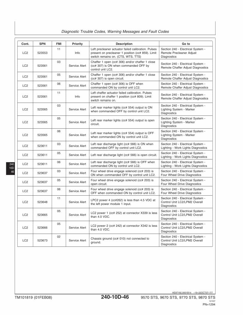
Diagnostic Trouble Codes, Warning Messages and Fault Codes
24010D
46
HE97192,0001B14 –19–22OCT07–7/7
Cont. SPN FMI Priority Description Go to
11 Left precleaner actuator failed calibration. Pulses Section 240 - Electrical System -LC2 523553 Info present on precleaner 1 position (cc# 859). Limit Remote Precleaner Adjust
switch remains on. (CTS, WTS, TTS) Diagnostics
03 Chaffer 1 open (cc# 306) and/or chaffer 1 closeSection 240 - Electrical System -
LC2 523561 Service Alert (cc# 307) is ON when commanded OFF byRemote Chaffer Adjust Diagnostics
control unit LC2.
05 Chaffer 1 open (cc# 306) and/or chaffer 1 close Section 240 - Electrical System -LC2 523561 Service Alert
(cc# 307) is open circuit. Remote Chaffer Adjust Diagnostics
06 Chaffer 1 open (cc# 306) is OFF when Section 240 - Electrical System -LC2 523561 Service Alert
commanded ON by control unit LC2. Remote Chaffer Adjust Diagnostics
11 Left chaffer actuator failed calibration. PulsesSection 240 - Electrical System -
LC2 523561 Info present on chaffer 1 position (cc# 809). LimitRemote Chaffer Adjust Diagnostics
switch remains on.
03 Section 240 - Electrical System -Left rear marker lights (cc# 554) output is ON
LC2 523565 Service Alert Lighting System - Markerwhen commanded OFF by control unit LC2.
Diagnostics
05 Section 240 - Electrical System -Left rear marker lights (cc# 554) output is open
LC2 523565 Service Alert Lighting System - Markercircuit.
Diagnostics
06 Section 240 - Electrical System -Left rear marker lights (cc# 554) output is OFF
LC2 523565 Service Alert Lighting System - Markerwhen commanded ON by control unit LC2.
Diagnostics
03 Left rear discharge light (cc# 566) is ON when Section 240 - Electrical System -LC2 523611 Service Alert
commanded OFF by control unit LC2. Lighting - Work Lights Diagnostics
05 Section 240 - Electrical System -LC2 523611 Service Alert Left rear discharge light (cc# 566) is open circuit.
Lighting - Work Lights Diagnostics
06 Left rear discharge light (cc# 566) is OFF when Section 240 - Electrical System -LC2 523611 Service Alert
commanded ON by control unit LC2. Lighting - Work Lights Diagnostics
03 Four wheel drive engage solenoid (cc# 203) is Section 240 - Electrical System -LC2 523637 Service Alert
ON when commanded OFF by control unit LC2. Four Wheel Drive Diagnostics
05 Four wheel drive engage solenoid (cc# 203) is Section 240 - Electrical System -LC2 523637 Service Alert
open circuit. Four Wheel Drive Diagnostics
06 Four wheel drive engage solenoid (cc# 203) is Section 240 - Electrical System -LC2 523637 Service Alert
OFF when commanded ON by control unit LC2. Four Wheel Drive Diagnostics
11 Section 240 - Electrical System -LPC2 power 4 (cc#262) is less than 4.5 VDC at
LC2 523648 Service Alert Control Unit LC2/LPM2 Overallthe left power module 1 input.
Diagnostics
05 Section 240 - Electrical System -LC2 power 1 (cc# 252) at connector X339 is less
LC2 523665 Service Alert Control Unit LC2/LPM2 Overallthan 4.0 VDC.
Diagnostics
05 Section 240 - Electrical System -LC2 power 2 (cc# 242) at connector X342 is less
LC2 523666 Service Alert Control Unit LC2/LPM2 Overallthan 4.0 VDC.
Diagnostics
02 Section 240 - Electrical System -Chassis ground (cc# 010) not connected to
LC2 523673 Service Alert Control Unit LC2/LPM2 Overallground.
Diagnostics
TM101819 (01FEB08) 240-10D-46 9570 STS, 9670 STS, 9770 STS, 9870 STS121507
PN=1294
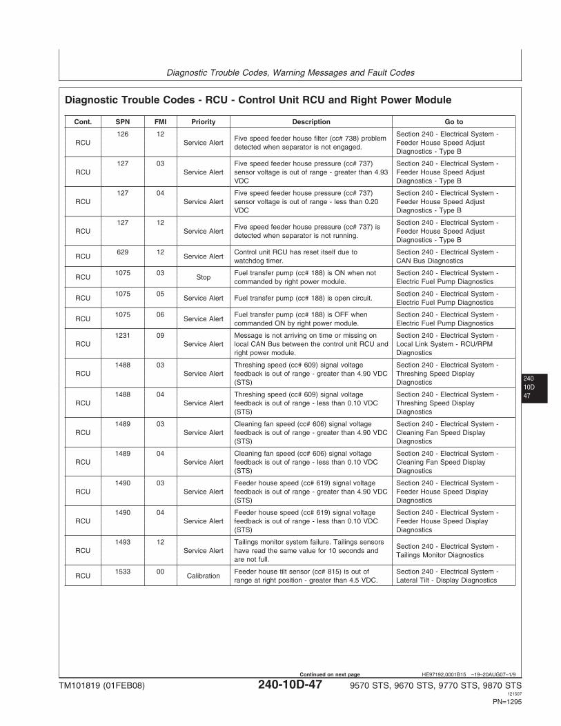
Diagnostic Trouble Codes, Warning Messages and Fault Codes
24010D47
HE97192,0001B15 –19–20AUG07–1/9
Diagnostic Trouble Codes - RCU - Control Unit RCU and Right Power Module
Cont. SPN FMI Priority Description Go to
126 12 Section 240 - Electrical System -Five speed feeder house filter (cc# 738) problem
RCU Service Alert Feeder House Speed Adjustdetected when separator is not engaged.
Diagnostics - Type B
127 03 Five speed feeder house pressure (cc# 737) Section 240 - Electrical System -RCU Service Alert sensor voltage is out of range - greater than 4.93 Feeder House Speed Adjust
VDC Diagnostics - Type B
127 04 Five speed feeder house pressure (cc# 737) Section 240 - Electrical System -RCU Service Alert sensor voltage is out of range - less than 0.20 Feeder House Speed Adjust
VDC Diagnostics - Type B
127 12 Section 240 - Electrical System -Five speed feeder house pressure (cc# 737) is
RCU Service Alert Feeder House Speed Adjustdetected when separator is not running.
Diagnostics - Type B
629 12 Control unit RCU has reset itself due to Section 240 - Electrical System -RCU Service Alert
watchdog timer. CAN Bus Diagnostics
1075 03 Fuel transfer pump (cc# 188) is ON when not Section 240 - Electrical System -RCU Stop
commanded by right power module. Electric Fuel Pump Diagnostics
1075 05 Section 240 - Electrical System -RCU Service Alert Fuel transfer pump (cc# 188) is open circuit.
Electric Fuel Pump Diagnostics
1075 06 Fuel transfer pump (cc# 188) is OFF when Section 240 - Electrical System -RCU Service Alert
commanded ON by right power module. Electric Fuel Pump Diagnostics
1231 09 Message is not arriving on time or missing on Section 240 - Electrical System -RCU Service Alert local CAN Bus between the control unit RCU and Local Link System - RCU/RPM
right power module. Diagnostics
1488 03 Threshing speed (cc# 609) signal voltage Section 240 - Electrical System -RCU Service Alert feedback is out of range - greater than 4.90 VDC Threshing Speed Display
(STS) Diagnostics
1488 04 Threshing speed (cc# 609) signal voltage Section 240 - Electrical System -RCU Service Alert feedback is out of range - less than 0.10 VDC Threshing Speed Display
(STS) Diagnostics
1489 03 Cleaning fan speed (cc# 606) signal voltage Section 240 - Electrical System -RCU Service Alert feedback is out of range - greater than 4.90 VDC Cleaning Fan Speed Display
(STS) Diagnostics
1489 04 Cleaning fan speed (cc# 606) signal voltage Section 240 - Electrical System -RCU Service Alert feedback is out of range - less than 0.10 VDC Cleaning Fan Speed Display
(STS) Diagnostics
1490 03 Feeder house speed (cc# 619) signal voltage Section 240 - Electrical System -RCU Service Alert feedback is out of range - greater than 4.90 VDC Feeder House Speed Display
(STS) Diagnostics
1490 04 Feeder house speed (cc# 619) signal voltage Section 240 - Electrical System -RCU Service Alert feedback is out of range - less than 0.10 VDC Feeder House Speed Display
(STS) Diagnostics
1493 12 Tailings monitor system failure. Tailings sensorsSection 240 - Electrical System -
RCU Service Alert have read the same value for 10 seconds andTailings Monitor Diagnostics
are not full.
1533 00 Feeder house tilt sensor (cc# 815) is out of Section 240 - Electrical System -RCU Calibration
range at right position - greater than 4.5 VDC. Lateral Tilt - Display Diagnostics
TM101819 (01FEB08) 240-10D-47 9570 STS, 9670 STS, 9770 STS, 9870 STS121507
PN=1295
Continued on next page
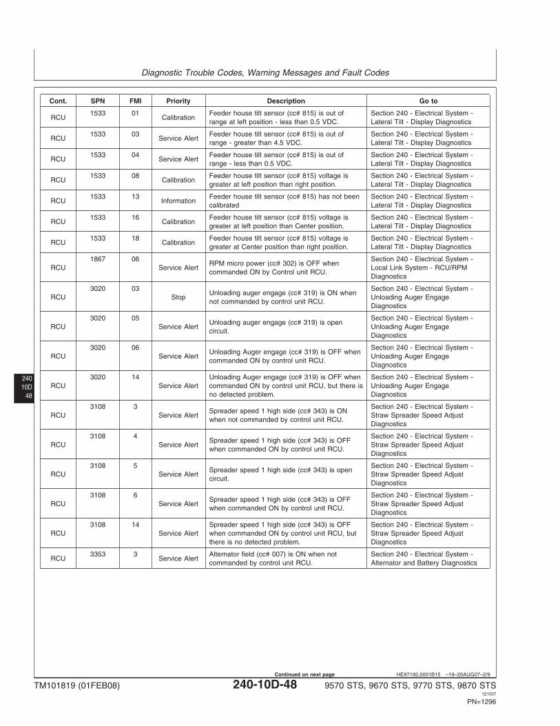
Diagnostic Trouble Codes, Warning Messages and Fault Codes
24010D
48
HE97192,0001B15 –19–20AUG07–2/9
Cont. SPN FMI Priority Description Go to
1533 01 Feeder house tilt sensor (cc# 815) is out of Section 240 - Electrical System -RCU Calibration
range at left position - less than 0.5 VDC. Lateral Tilt - Display Diagnostics
1533 03 Feeder house tilt sensor (cc# 815) is out of Section 240 - Electrical System -RCU Service Alert
range - greater than 4.5 VDC. Lateral Tilt - Display Diagnostics
1533 04 Feeder house tilt sensor (cc# 815) is out of Section 240 - Electrical System -RCU Service Alert
range - less than 0.5 VDC. Lateral Tilt - Display Diagnostics
1533 08 Feeder house tilt sensor (cc# 815) voltage is Section 240 - Electrical System -RCU Calibration
greater at left position than right position. Lateral Tilt - Display Diagnostics
1533 13 Feeder house tilt sensor (cc# 815) has not been Section 240 - Electrical System -RCU Information
calibrated Lateral Tilt - Display Diagnostics
1533 16 Feeder house tilt sensor (cc# 815) voltage is Section 240 - Electrical System -RCU Calibration
greater at left position than Center position. Lateral Tilt - Display Diagnostics
1533 18 Feeder house tilt sensor (cc# 815) voltage is Section 240 - Electrical System -RCU Calibration
greater at Center position than right position. Lateral Tilt - Display Diagnostics
1867 06 Section 240 - Electrical System -RPM micro power (cc# 302) is OFF when
RCU Service Alert Local Link System - RCU/RPMcommanded ON by Control unit RCU.
Diagnostics
3020 03 Section 240 - Electrical System -Unloading auger engage (cc# 319) is ON when
RCU Stop Unloading Auger Engagenot commanded by control unit RCU.
Diagnostics
3020 05 Section 240 - Electrical System -Unloading auger engage (cc# 319) is open
RCU Service Alert Unloading Auger Engagecircuit.
Diagnostics
3020 06 Section 240 - Electrical System -Unloading Auger engage (cc# 319) is OFF when
RCU Service Alert Unloading Auger Engagecommanded ON by control unit RCU.
Diagnostics
3020 14 Unloading Auger engage (cc# 319) is OFF when Section 240 - Electrical System -RCU Service Alert commanded ON by control unit RCU, but there is Unloading Auger Engage
no detected problem. Diagnostics
3108 3 Section 240 - Electrical System -Spreader speed 1 high side (cc# 343) is ON
RCU Service Alert Straw Spreader Speed Adjustwhen not commanded by control unit RCU.
Diagnostics
3108 4 Section 240 - Electrical System -Spreader speed 1 high side (cc# 343) is OFF
RCU Service Alert Straw Spreader Speed Adjustwhen commanded ON by control unit RCU.
Diagnostics
3108 5 Section 240 - Electrical System -Spreader speed 1 high side (cc# 343) is open
RCU Service Alert Straw Spreader Speed Adjustcircuit.
Diagnostics
3108 6 Section 240 - Electrical System -Spreader speed 1 high side (cc# 343) is OFF
RCU Service Alert Straw Spreader Speed Adjustwhen commanded ON by control unit RCU.
Diagnostics
3108 14 Spreader speed 1 high side (cc# 343) is OFF Section 240 - Electrical System -RCU Service Alert when commanded ON by control unit RCU, but Straw Spreader Speed Adjust
there is no detected problem. Diagnostics
3353 3 Alternator field (cc# 007) is ON when not Section 240 - Electrical System -RCU Service Alert
commanded by control unit RCU. Alternator and Battery Diagnostics
TM101819 (01FEB08) 240-10D-48 9570 STS, 9670 STS, 9770 STS, 9870 STS121507
PN=1296
Continued on next page
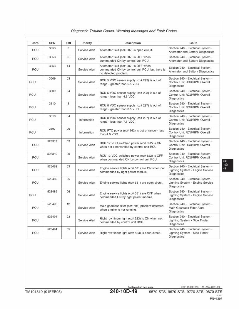
Diagnostic Trouble Codes, Warning Messages and Fault Codes
24010D49
HE97192,0001B15 –19–20AUG07–3/9
Cont. SPN FMI Priority Description Go to
3353 5 Section 240 - Electrical System -RCU Service Alert Alternator field (cc# 007) is open circuit.
Alternator and Battery Diagnostics
3353 6 Alternator field (cc# 007) is OFF when Section 240 - Electrical System -RCU Service Alert
commanded ON by control unit RCU. Alternator and Battery Diagnostics
3353 14 Alternator field (cc# 007) is OFF whenSection 240 - Electrical System -
RCU Service Alert commanded ON by control unit RCU, but there isAlternator and Battery Diagnostics
no detected problem.
3509 03 Section 240 - Electrical System -RCU 5 VDC sensor supply (cc# 293) is out of
RCU Service Alert Control Unit RCU/RPM Overallrange - greater than 5.5 VDC.
Diagnostics
3509 04 Section 240 - Electrical System -RCU 5 VDC sensor supply (cc# 293) is out of
RCU Service Alert Control Unit RCU/RPM Overallrange - less than 4.5 VDC.
Diagnostics
3510 3 Section 240 - Electrical System -RCU 8 VDC sensor supply (cc# 297) is out of
RCU Service Alert Control Unit RCU/RPM Overallrange - greater than 8.5 VDC.
Diagnostics
3510 04 Section 240 - Electrical System -RCU 8 VDC sensor supply (cc# 297) is out of
RCU Information Control Unit RCU/RPM Overallrange - less than 7.5 VDC.
Diagnostics
3597 06 Section 240 - Electrical System -RCU PTC power (cc# 562) is out of range - less
RCU Information Control Unit RCU/RPM Overallthan 4.0 VDC.
Diagnostics
523319 03 Section 240 - Electrical System -RCU 12 VDC switched power (cc# 822) is ON
RCU Service Alert Control Unit RCU/RPM Overallwhen not commanded by control unit RCU.
Diagnostics
523319 06 Section 240 - Electrical System -RCU 12 VDC switched power (cc# 822) is OFF
RCU Service Alert Control Unit RCU/RPM Overallwhen commanded ON by control unit RCU.
Diagnostics
523489 03 Section 240 - Electrical System -Engine service lights (cc# 531) are ON when not
RCU Service Alert Lighting System - Engine Servicecommanded by right power module.
Diagnostics
523489 05 Section 240 - Electrical System -RCU Service Alert Engine service lights (cc# 531) are open circuit. Lighting System - Engine Service
Diagnostics
523489 06 Section 240 - Electrical System -Engine service lights (cc# 531) are OFF when
RCU Service Alert Lighting System - Engine Servicecommanded ON by right power module.
Diagnostics
523493 12 Section 240 - Electrical System -Main gearcase filter (cc# 701) problem detected
RCU Service Alert Main Gearcase Filter Alertwhen engine is not running.
Diagnostics
523494 03 Section 240 - Electrical System -Right row finder light (cc# 523) is ON when not
RCU Service Alert Lighting System - Side Findercommanded by control unit RCU.
Diagnostics
523494 05 Section 240 - Electrical System -RCU Service Alert Right row finder light (cc# 523) is open circuit. Lighting System - Side Finder
Diagnostics
TM101819 (01FEB08) 240-10D-49 9570 STS, 9670 STS, 9770 STS, 9870 STS121507
PN=1297
Continued on next page
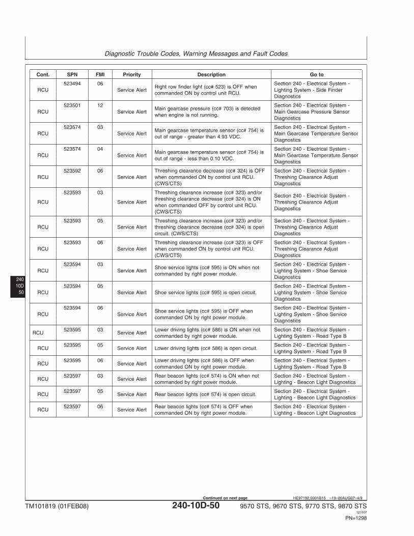
Diagnostic Trouble Codes, Warning Messages and Fault Codes
24010D
50
HE97192,0001B15 –19–20AUG07–4/9
Cont. SPN FMI Priority Description Go to
523494 06 Section 240 - Electrical System -Right row finder light (cc# 523) is OFF when
RCU Service Alert Lighting System - Side Findercommanded ON by control unit RCU.
Diagnostics
523501 12 Section 240 - Electrical System -Main gearcase pressure (cc# 703) is detected
RCU Service Alert Main Gearcase Pressure Sensorwhen engine is not running.
Diagnostics
523574 03 Section 240 - Electrical System -Main gearcase temperature sensor (cc# 754) is
RCU Service Alert Main Gearcase Temperature Sensorout of range - greater than 4.93 VDC.
Diagnostics
523574 04 Section 240 - Electrical System -Main gearcase temperature sensor (cc# 754) is
RCU Service Alert Main Gearcase Temperature Sensorout of range - less than 0.10 VDC.
Diagnostics
523592 06 Threshing clearance decrease (cc# 324) is OFF Section 240 - Electrical System -RCU Service Alert when commanded ON by control unit RCU. Threshing Clearance Adjust
(CWS/CTS) Diagnostics
523593 03 Threshing clearance increase (cc# 323) and/orSection 240 - Electrical System -
threshing clearance decrease (cc# 324) is ONRCU Service Alert Threshing Clearance Adjust
when commanded OFF by control unit RCU.Diagnostics
(CWS/CTS)
523593 05 Threshing clearance increase (cc# 323) and/or Section 240 - Electrical System -RCU Service Alert threshing clearance decrease (cc# 324) is open Threshing Clearance Adjust
circuit. (CWS/CTS) Diagnostics
523593 06 Threshing clearance increase (cc# 323) is OFF Section 240 - Electrical System -RCU Service Alert when commanded ON by control unit RCU. Threshing Clearance Adjust
(CWS/CTS) Diagnostics
523594 03 Section 240 - Electrical System -Shoe service lights (cc# 595) is ON when not
RCU Service Alert Lighting System - Shoe Servicecommanded by right power module.
Diagnostics
523594 05 Section 240 - Electrical System -RCU Service Alert Shoe service lights (cc# 595) is open circuit. Lighting System - Shoe Service
Diagnostics
523594 06 Section 240 - Electrical System -Shoe service lights (cc# 595) is OFF when
RCU Service Alert Lighting System - Shoe Servicecommanded ON by right power module.
Diagnostics
523595 03 Lower driving lights (cc# 586) is ON when not Section 240 - Electrical System -RCU Service Alert
commanded by right power module. Lighting System - Road Type B
523595 05 Section 240 - Electrical System -RCU Service Alert Lower driving lights (cc# 586) is open circuit.
Lighting System - Road Type B
523595 06 Lower driving lights (cc# 586) is OFF when Section 240 - Electrical System -RCU Service Alert
commanded ON by right power module. Lighting System - Road Type B
523597 03 Rear beacon lights (cc# 574) is ON when not Section 240 - Electrical System -RCU Service Alert
commanded by right power module. Lighting - Beacon Light Diagnostics
523597 05 Section 240 - Electrical System -RCU Service Alert Rear beacon lights (cc# 574) is open circuit.
Lighting - Beacon Light Diagnostics
523597 06 Rear beacon lights (cc# 574) is OFF when Section 240 - Electrical System -RCU Service Alert
commanded ON by right power module. Lighting - Beacon Light Diagnostics
TM101819 (01FEB08) 240-10D-50 9570 STS, 9670 STS, 9770 STS, 9870 STS121507
PN=1298
Continued on next page
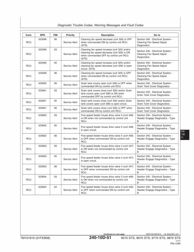
Diagnostic Trouble Codes, Warning Messages and Fault Codes
24010D51
HE97192,0001B15 –19–20AUG07–5/9
Cont. SPN FMI Priority Description Go to
523598 06 Cleaning fan speed decrease (cc# 326) is OFF Section 240 - Electrical System -RCU Service Alert when commanded ON by control unit RCU. Cleaning Fan Speed Adjust
(STS) Diagnostics
523599 03 Cleaning fan speed increase (cc# 325) and/orSection 240 - Electrical System -
cleaning fan speed decrease (cc# 326) is ONRCU Service Alert Cleaning Fan Speed Adjust
when commanded OFF by control unit RCU.Diagnostics
(STS)
523599 05 Cleaning fan speed increase (cc# 325) and/or Section 240 - Electrical System -RCU Service Alert cleaning fan speed decrease (cc# 326) is open Cleaning Fan Speed Adjust
circuit. (STS) Diagnostics
523599 06 Cleaning fan speed increase (cc# 325) is OFF Section 240 - Electrical System -RCU Service Alert when commanded ON by control unit RCU. Cleaning Fan Speed Adjust
(STS) Diagnostics
523600 06 Grain tank covers open (cc# 336) is OFF when Section 240 - Electrical System -RCU Service Alert
commanded ON by control unit RCU. Grain Tank Cover Diagnostics
523601 03 Grain tank covers close (cc# 335) and/or GrainSection 240 - Electrical System -
RCU Service Alert tank covers open (cc# 336) is ON whenGrain Tank Cover Diagnostics
commanded OFF by control unit RCU.
523601 05 Grain tank covers close (cc# 335) and/or Grain Section 240 - Electrical System -RCU Service Alert
tank covers open (cc# 336) is open circuit. Grain Tank Cover Diagnostics
523601 06 Grain tank covers close (cc# 335) is OFF when Section 240 - Electrical System -RCU Service Alert
commanded ON by control unit RCU. Grain Tank Cover Diagnostics
523602 03 Five speed feeder house drive valve 5 (cc# 448) Section 240 - Electrical System -RCU Service Alert is ON when not commanded by control unit Header Engage Diagnostics - Type
RCU. B
523602 05 Section 240 - Electrical System -Five speed feeder house drive valve 5 (cc# 448)
RCU Service Alert Header Engage Diagnostics - Typeis open circuit.
B
523602 06 Five speed feeder house drive valve 5 (cc# 448) Section 240 - Electrical System -RCU Service Alert is OFF when commanded ON by control unit Header Engage Diagnostics - Type
RCU. B
523603 03 Five speed feeder house drive valve 4 (cc# 447) Section 240 - Electrical System -RCU Service Alert is ON when not commanded by control unit Header Engage Diagnostics - Type
RCU. B
523603 05 Section 240 - Electrical System -Five speed feeder house drive valve 4 (cc# 447)
RCU Service Alert Header Engage Diagnostics - Typeis open circuit.
B
523603 06 Five speed feeder house drive valve 4 (cc# 447) Section 240 - Electrical System -RCU Service Alert is OFF when commanded ON by control unit Header Engage Diagnostics - Type
RCU. B
523604 03 Five speed feeder house drive valve 3 (cc# 446) Section 240 - Electrical System -RCU Service Alert is ON when not commanded by control unit Header Engage Diagnostics - Type
RCU. B
523604 04 Five speed feeder house drive valve 3 (cc# 446) Section 240 - Electrical System -RCU Service Alert is OFF when commanded ON by control unit Header Engage Diagnostics - Type
RCU. B
TM101819 (01FEB08) 240-10D-51 9570 STS, 9670 STS, 9770 STS, 9870 STS121507
PN=1299
Continued on next page
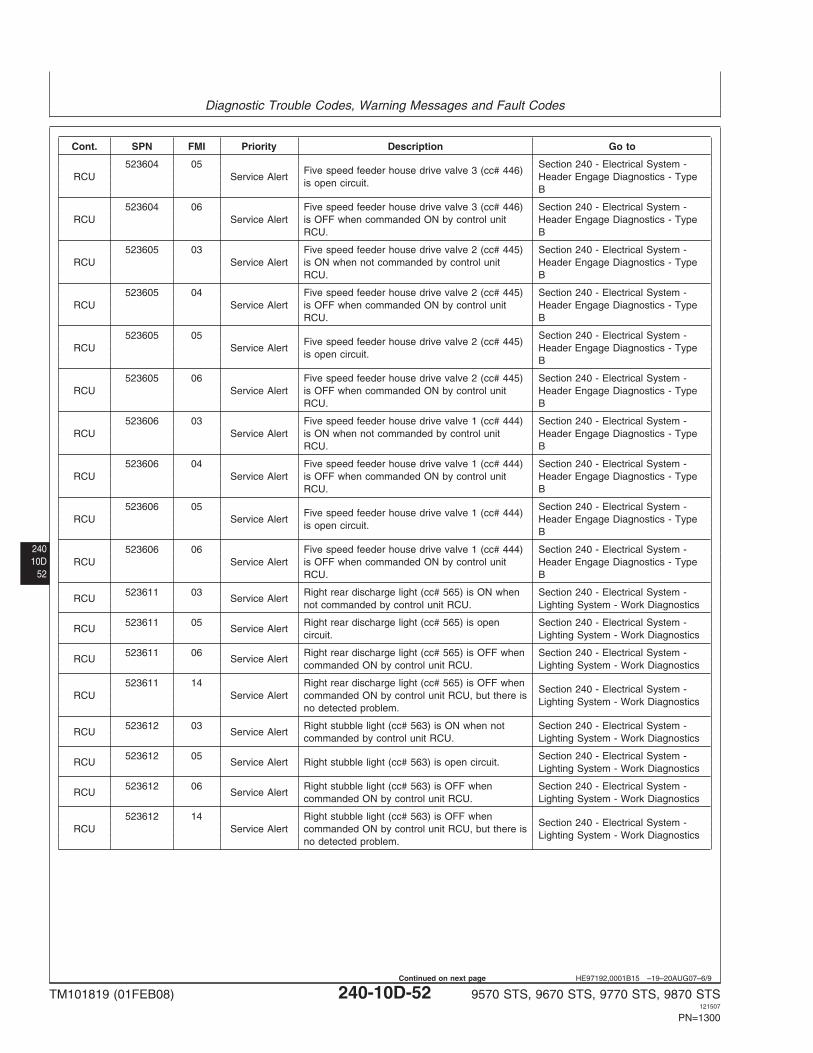
Diagnostic Trouble Codes, Warning Messages and Fault Codes
24010D
52
HE97192,0001B15 –19–20AUG07–6/9
Cont. SPN FMI Priority Description Go to
523604 05 Section 240 - Electrical System -Five speed feeder house drive valve 3 (cc# 446)
RCU Service Alert Header Engage Diagnostics - Typeis open circuit.
B
523604 06 Five speed feeder house drive valve 3 (cc# 446) Section 240 - Electrical System -RCU Service Alert is OFF when commanded ON by control unit Header Engage Diagnostics - Type
RCU. B
523605 03 Five speed feeder house drive valve 2 (cc# 445) Section 240 - Electrical System -RCU Service Alert is ON when not commanded by control unit Header Engage Diagnostics - Type
RCU. B
523605 04 Five speed feeder house drive valve 2 (cc# 445) Section 240 - Electrical System -RCU Service Alert is OFF when commanded ON by control unit Header Engage Diagnostics - Type
RCU. B
523605 05 Section 240 - Electrical System -Five speed feeder house drive valve 2 (cc# 445)
RCU Service Alert Header Engage Diagnostics - Typeis open circuit.
B
523605 06 Five speed feeder house drive valve 2 (cc# 445) Section 240 - Electrical System -RCU Service Alert is OFF when commanded ON by control unit Header Engage Diagnostics - Type
RCU. B
523606 03 Five speed feeder house drive valve 1 (cc# 444) Section 240 - Electrical System -RCU Service Alert is ON when not commanded by control unit Header Engage Diagnostics - Type
RCU. B
523606 04 Five speed feeder house drive valve 1 (cc# 444) Section 240 - Electrical System -RCU Service Alert is OFF when commanded ON by control unit Header Engage Diagnostics - Type
RCU. B
523606 05 Section 240 - Electrical System -Five speed feeder house drive valve 1 (cc# 444)
RCU Service Alert Header Engage Diagnostics - Typeis open circuit.
B
523606 06 Five speed feeder house drive valve 1 (cc# 444) Section 240 - Electrical System -RCU Service Alert is OFF when commanded ON by control unit Header Engage Diagnostics - Type
RCU. B
523611 03 Right rear discharge light (cc# 565) is ON when Section 240 - Electrical System -RCU Service Alert
not commanded by control unit RCU. Lighting System - Work Diagnostics
523611 05 Right rear discharge light (cc# 565) is open Section 240 - Electrical System -RCU Service Alert
circuit. Lighting System - Work Diagnostics
523611 06 Right rear discharge light (cc# 565) is OFF when Section 240 - Electrical System -RCU Service Alert
commanded ON by control unit RCU. Lighting System - Work Diagnostics
523611 14 Right rear discharge light (cc# 565) is OFF whenSection 240 - Electrical System -
RCU Service Alert commanded ON by control unit RCU, but there isLighting System - Work Diagnostics
no detected problem.
523612 03 Right stubble light (cc# 563) is ON when not Section 240 - Electrical System -RCU Service Alert
commanded by control unit RCU. Lighting System - Work Diagnostics
523612 05 Section 240 - Electrical System -RCU Service Alert Right stubble light (cc# 563) is open circuit.
Lighting System - Work Diagnostics
523612 06 Right stubble light (cc# 563) is OFF when Section 240 - Electrical System -RCU Service Alert
commanded ON by control unit RCU. Lighting System - Work Diagnostics
523612 14 Right stubble light (cc# 563) is OFF whenSection 240 - Electrical System -
RCU Service Alert commanded ON by control unit RCU, but there isLighting System - Work Diagnostics
no detected problem.
TM101819 (01FEB08) 240-10D-52 9570 STS, 9670 STS, 9770 STS, 9870 STS121507
PN=1300
Continued on next page
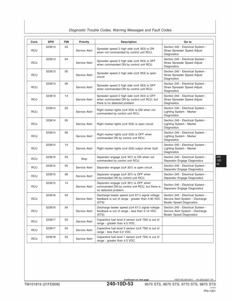
Diagnostic Trouble Codes, Warning Messages and Fault Codes
24010D53
HE97192,0001B15 –19–20AUG07–7/9
Cont. SPN FMI Priority Description Go to
523613 03 Section 240 - Electrical System -Spreader speed 2 high side (cc# 353) is ON
RCU Service Alert Straw Spreader Speed Adjustwhen not commanded by control unit RCU.
Diagnostics
523613 04 Section 240 - Electrical System -Spreader speed 2 high side (cc# 353) is OFF
RCU Service Alert Straw Spreader Speed Adjustwhen commanded ON by control unit RCU.
Diagnostics
523613 05 Section 240 - Electrical System -Spreader speed 2 high side (cc# 353) is open
RCU Service Alert Straw Spreader Speed Adjustcircuit.
Diagnostics
523613 06 Section 240 - Electrical System -Spreader speed 2 high side (cc# 353) is OFF
RCU Service Alert Straw Spreader Speed Adjustwhen commanded ON by control unit RCU.
Diagnostics
523613 14 Spreader speed 2 high side (cc# 353) is OFF Section 240 - Electrical System -RCU Service Alert when commanded ON by control unit RCU, but Straw Spreader Speed Adjust
there is no detected problem. Diagnostics
523614 03 Section 240 - Electrical System -Right marker lights (cc# 553) is ON when not
RCU Service Alert Lighting System - Markercommanded by control unit RCU.
Diagnostics
523614 05 Section 240 - Electrical System -RCU Service Alert Right marker lights (cc# 553) is open circuit. Lighting System - Marker
Diagnostics
523614 06 Section 240 - Electrical System -Right marker lights (cc# 553) is OFF when
RCU Service Alert Lighting System - Markercommanded ON by control unit RCU.
Diagnostics
523614 14 Section 240 - Electrical System -RCU Service Alert Right marker lights (cc# 553) output driver fault Lighting System - Marker
Diagnostics
523615 03 Separator engage (cc# 301) is ON when not Section 240 - Electrical System -RCU Stop
commanded by control unit RCU. Separator Engage Diagnostics
523615 05 Section 240 - Electrical System -RCU Service Alert Separator engage (cc# 301) is open circuit.
Separator Engage Diagnostics
523615 06 Separator engage (cc# 301) is OFF when Section 240 - Electrical System -RCU Service Alert
commanded ON by control unit RCU. Separator Engage Diagnostics
523615 14 Separator engage (cc# 301) is OFF whenSection 240 - Electrical System -
RCU Service Alert commanded ON by control unit RCU, but there isSeparator Engage Diagnostics
no detected problem.
523616 03 Discharge beater speed (cc# 611) signal voltage Section 240 - Electrical System -RCU Service Alert feedback is out of range - greater than 4.90 VDC Service Alert System - Discharge
(STS) Beater Speed Diagnostics
523616 04 Discharge beater speed (cc# 611) signal voltage Section 240 - Electrical System -RCU Service Alert feedback is out of range - less than 0.10 VDC Service Alert System - Discharge
(STS) Beater Speed Diagnostics
523617 03 Capacitive fuel level 2 sensor (cc# 756) is out ofRCU Service Alert
range - greater than 4.5 VDC.
523617 04 Capacitive fuel level 2 sensor (cc# 756) is out ofRCU Service Alert
range - less than 0.2 VDC.
523618 03 Capacitive fuel level 1 sensor (cc# 755) is out ofRCU Service Alert
range - greater than 4.5 VDC.
TM101819 (01FEB08) 240-10D-53 9570 STS, 9670 STS, 9770 STS, 9870 STS121507
PN=1301
Continued on next page
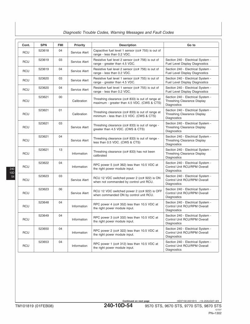
Diagnostic Trouble Codes, Warning Messages and Fault Codes
24010D
54
HE97192,0001B15 –19–20AUG07–8/9
Cont. SPN FMI Priority Description Go to
523618 04 Capacitive fuel level 1 sensor (cc# 755) is out ofRCU Service Alert
range - less than 0.2 VDC.
523619 03 Resistive fuel level 2 sensor (cc# 756) is out of Section 240 - Electrical System -RCU Service Alert
range - greater than 4.5 VDC. Fuel Level Display Diagnostics
523619 04 Resistive fuel level 2 sensor (cc# 756) is out of Section 240 - Electrical System -RCU Service Alert
range - less than 0.2 VDC. Fuel Level Display Diagnostics
523620 03 Resistive fuel level 1 sensor (cc# 755) is out of Section 240 - Electrical System -RCU Service Alert
range - greater than 4.5 VDC. Fuel Level Display Diagnostics
523620 04 Resistive fuel level 1 sensor (cc# 755) is out of Section 240 - Electrical System -RCU Service Alert
range - less than 0.2 VDC. Fuel Level Display Diagnostics
523621 00 Section 240 - Electrical System -Threshing clearance (cc# 833) is out of range at
RCU Calibration Threshing Clearance Displaymaximum - greater than 4.5 VDC. (CWS & CTS)
Diagnostics
523621 01 Section 240 - Electrical System -Threshing clearance (cc# 833) is out of range at
RCU Calibration Threshing Clearance Displayminimum - less than 2.5 VDC. (CWS & CTS)
Diagnostics
523621 03 Section 240 - Electrical System -Threshing clearance (cc# 833) is out of range -
RCU Service Alert Threshing Clearance Displaygreater than 4.5 VDC. (CWS & CTS)
Diagnostics
523621 04 Section 240 - Electrical System -Threshing clearance (cc# 833) is out of range -
RCU Service Alert Threshing Clearance Displayless than 0.5 VDC. (CWS & CTS)
Diagnostics
523621 13 Section 240 - Electrical System -Threshing clearance (cc# 833) has not been
RCU Information Threshing Clearance Displaycalibrated
Diagnostics
523622 04 Section 240 - Electrical System -RPC power 5 (cc# 362) less than 10.5 VDC at
RCU Information Control Unit RCU/RPM Overallthe right power module input.
Diagnostics
523623 03 Section 240 - Electrical System -RCU 12 VDC switched power 2 (cc# 922) is ON
RCU Service Alert Control Unit RCU/RPM Overallwhen not commanded by control unit RCU.
Diagnostics
523623 06 Section 240 - Electrical System -RCU 12 VDC switched power 2 (cc# 922) is OFF
RCU Service Alert Control Unit RCU/RPM Overallwhen commanded ON by control unit RCU.
Diagnostics
523648 04 Section 240 - Electrical System -RPC power 4 (cc# 352) less than 10.5 VDC at
RCU Information Control Unit RCU/RPM Overallthe right power module input.
Diagnostics
523649 04 Section 240 - Electrical System -RPC power 3 (cc# 332) less than 10.5 VDC at
RCU Information Control Unit RCU/RPM Overallthe right power module input.
Diagnostics
523650 04 Section 240 - Electrical System -RPC power 2 (cc# 322) less than 10.5 VDC at
RCU Information Control Unit RCU/RPM Overallthe right power module input.
Diagnostics
523653 04 Section 240 - Electrical System -RPC power 1 (cc# 312) less than 10.5 VDC at
RCU Information Control Unit RCU/RPM Overallthe right power module input.
Diagnostics
TM101819 (01FEB08) 240-10D-54 9570 STS, 9670 STS, 9770 STS, 9870 STS121507
PN=1302
Continued on next page
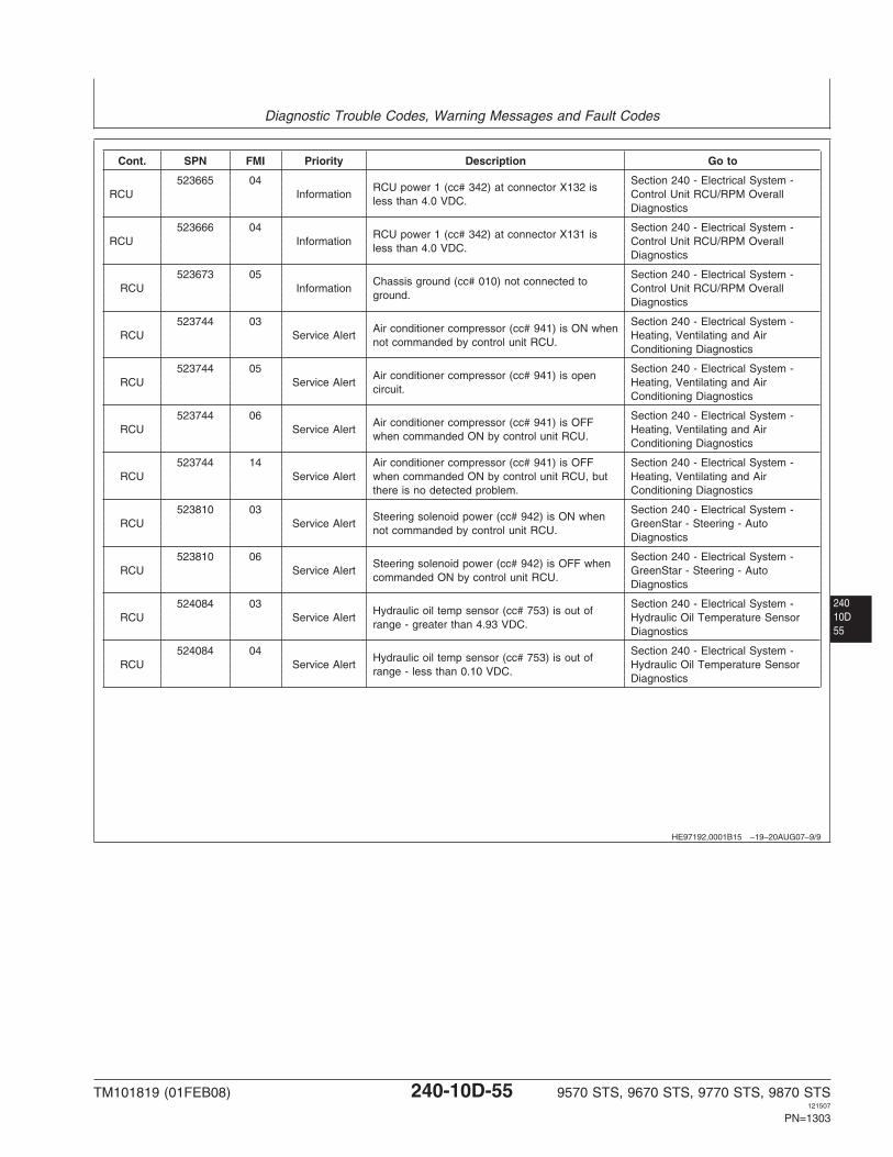
Diagnostic Trouble Codes, Warning Messages and Fault Codes
24010D55
HE97192,0001B15 –19–20AUG07–9/9
Cont. SPN FMI Priority Description Go to
523665 04 Section 240 - Electrical System -RCU power 1 (cc# 342) at connector X132 is
RCU Information Control Unit RCU/RPM Overallless than 4.0 VDC.
Diagnostics
523666 04 Section 240 - Electrical System -RCU power 1 (cc# 342) at connector X131 is
RCU Information Control Unit RCU/RPM Overallless than 4.0 VDC.
Diagnostics
523673 05 Section 240 - Electrical System -Chassis ground (cc# 010) not connected to
RCU Information Control Unit RCU/RPM Overallground.
Diagnostics
523744 03 Section 240 - Electrical System -Air conditioner compressor (cc# 941) is ON when
RCU Service Alert Heating, Ventilating and Airnot commanded by control unit RCU.
Conditioning Diagnostics
523744 05 Section 240 - Electrical System -Air conditioner compressor (cc# 941) is open
RCU Service Alert Heating, Ventilating and Aircircuit.
Conditioning Diagnostics
523744 06 Section 240 - Electrical System -Air conditioner compressor (cc# 941) is OFF
RCU Service Alert Heating, Ventilating and Airwhen commanded ON by control unit RCU.
Conditioning Diagnostics
523744 14 Air conditioner compressor (cc# 941) is OFF Section 240 - Electrical System -RCU Service Alert when commanded ON by control unit RCU, but Heating, Ventilating and Air
there is no detected problem. Conditioning Diagnostics
523810 03 Section 240 - Electrical System -Steering solenoid power (cc# 942) is ON when
RCU Service Alert GreenStar - Steering - Autonot commanded by control unit RCU.
Diagnostics
523810 06 Section 240 - Electrical System -Steering solenoid power (cc# 942) is OFF when
RCU Service Alert GreenStar - Steering - Autocommanded ON by control unit RCU.
Diagnostics
524084 03 Section 240 - Electrical System -Hydraulic oil temp sensor (cc# 753) is out of
RCU Service Alert Hydraulic Oil Temperature Sensorrange - greater than 4.93 VDC.
Diagnostics
524084 04 Section 240 - Electrical System -Hydraulic oil temp sensor (cc# 753) is out of
RCU Service Alert Hydraulic Oil Temperature Sensorrange - less than 0.10 VDC.
Diagnostics
TM101819 (01FEB08) 240-10D-55 9570 STS, 9670 STS, 9770 STS, 9870 STS121507
PN=1303
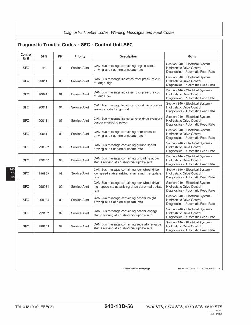
Diagnostic Trouble Codes, Warning Messages and Fault Codes
24010D
56
HE97192,0001B19 –19–05JUN07–1/2
Diagnostic Trouble Codes - SFC - Control Unit SFC
ControlSPN FMI Priority Description Go to
Unit
Section 240 - Electrical System -CAN Bus message containing engine speed
SFC 190 09 Service Alert Hydrostatic Drive Controlarriving at an abnormal update rate
Diagnostics - Automatic Feed Rate
Section 240 - Electrical System -CAN Bus message indicates rotor pressure out
SFC 200411 00 Service Alert Hydrostatic Drive Controlof range high
Diagnostics - Automatic Feed Rate
Section 240 - Electrical System -CAN Bus message indicates rotor pressure out
SFC 200411 01 Service Alert Hydrostatic Drive Controlof range low
Diagnostics - Automatic Feed Rate
Section 240 - Electrical System -CAN Bus message indicates rotor drive pressure
SFC 200411 04 Service Alert Hydrostatic Drive Controlsensor shorted to ground
Diagnostics - Automatic Feed Rate
Section 240 - Electrical System -CAN Bus message indicates rotor drive pressure
SFC 200411 05 Service Alert Hydrostatic Drive Controlsensor shorted to power
Diagnostics - Automatic Feed Rate
Section 240 - Electrical System -CAN Bus message containing rotor pressure
SFC 200411 09 Service Alert Hydrostatic Drive Controlarriving at an abnormal update rate
Diagnostics - Automatic Feed Rate
Section 240 - Electrical System -CAN Bus message containing ground speed
SFC 298682 09 Service Alert Hydrostatic Drive Controlarriving at an abnormal update rate
Diagnostics - Automatic Feed Rate
Section 240 - Electrical System -CAN Bus message containing unloading auger
SFC 298982 09 Service Alert Hydrostatic Drive Controlstatus arriving at an abnormal update rate
Diagnostics - Automatic Feed Rate
CAN Bus message containing four wheel drive Section 240 - Electrical System -SFC 298983 09 Service Alert low speed status arriving at an abnormal update Hydrostatic Drive Control
rate Diagnostics - Automatic Feed Rate
CAN Bus message containing four wheel drive Section 240 - Electrical System -SFC 298984 09 Service Alert high speed status arriving at an abnormal update Hydrostatic Drive Control
rate Diagnostics - Automatic Feed Rate
Section 240 - Electrical System -CAN Bus message containing header height
SFC 299084 09 Service Alert Hydrostatic Drive Controlarriving at an abnormal update rate
Diagnostics - Automatic Feed Rate
Section 240 - Electrical System -CAN Bus message containing header engage
SFC 299102 09 Service Alert Hydrostatic Drive Controlstatus arriving at an abnormal update rate
Diagnostics - Automatic Feed Rate
Section 240 - Electrical System -CAN Bus message containing separator engage
SFC 299103 09 Service Alert Hydrostatic Drive Controlstatus arriving at an abnormal update rate
Diagnostics - Automatic Feed Rate
Continued on next page
TM101819 (01FEB08) 240-10D-56 9570 STS, 9670 STS, 9770 STS, 9870 STS121507
PN=1304
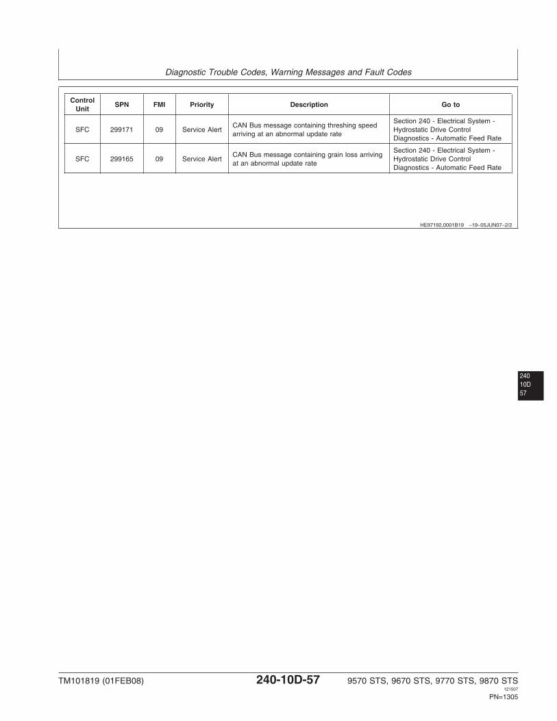
Diagnostic Trouble Codes, Warning Messages and Fault Codes
HE97192,0001B19 –19–05JUN07–2/2
ControlSPN FMI Priority Description Go to
Unit
Section 240 - Electrical System -CAN Bus message containing threshing speed
SFC 299171 09 Service Alert Hydrostatic Drive Controlarriving at an abnormal update rate
Diagnostics - Automatic Feed Rate
Section 240 - Electrical System -CAN Bus message containing grain loss arriving
SFC 299165 09 Service Alert Hydrostatic Drive Controlat an abnormal update rate
Diagnostics - Automatic Feed Rate
24010D57
TM101819 (01FEB08) 240-10D-57 9570 STS, 9670 STS, 9770 STS, 9870 STS121507
PN=1305
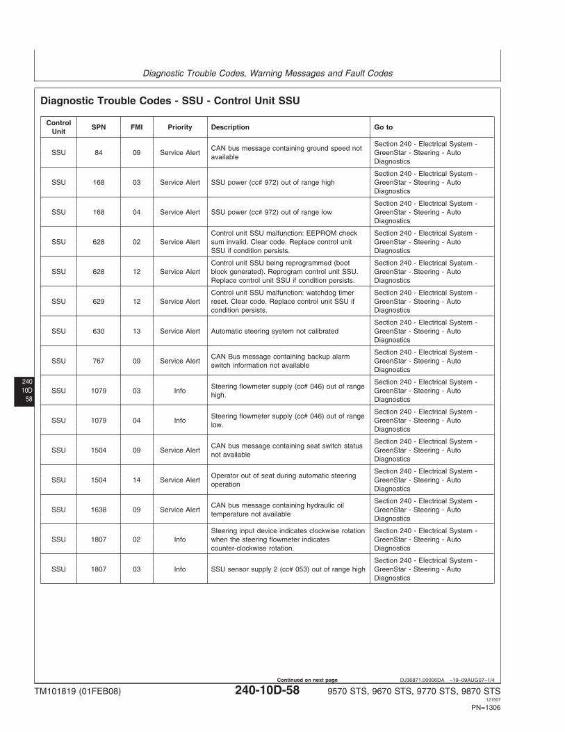
Diagnostic Trouble Codes, Warning Messages and Fault Codes
24010D
58
DJ36871,00006DA –19–09AUG07–1/4
Diagnostic Trouble Codes - SSU - Control Unit SSU
ControlSPN FMI Priority Description Go to
Unit
Section 240 - Electrical System -CAN bus message containing ground speed not
SSU 84 09 Service Alert GreenStar - Steering - Autoavailable
Diagnostics
Section 240 - Electrical System -SSU 168 03 Service Alert SSU power (cc# 972) out of range high GreenStar - Steering - Auto
Diagnostics
Section 240 - Electrical System -SSU 168 04 Service Alert SSU power (cc# 972) out of range low GreenStar - Steering - Auto
Diagnostics
Control unit SSU malfunction: EEPROM check Section 240 - Electrical System -SSU 628 02 Service Alert sum invalid. Clear code. Replace control unit GreenStar - Steering - Auto
SSU if condition persists. Diagnostics
Control unit SSU being reprogrammed (boot Section 240 - Electrical System -SSU 628 12 Service Alert block generated). Reprogram control unit SSU. GreenStar - Steering - Auto
Replace control unit SSU if condition persists. Diagnostics
Control unit SSU malfunction: watchdog timer Section 240 - Electrical System -SSU 629 12 Service Alert reset. Clear code. Replace control unit SSU if GreenStar - Steering - Auto
condition persists. Diagnostics
Section 240 - Electrical System -SSU 630 13 Service Alert Automatic steering system not calibrated GreenStar - Steering - Auto
Diagnostics
Section 240 - Electrical System -CAN Bus message containing backup alarm
SSU 767 09 Service Alert GreenStar - Steering - Autoswitch information not available
Diagnostics
Section 240 - Electrical System -Steering flowmeter supply (cc# 046) out of range
SSU 1079 03 Info GreenStar - Steering - Autohigh.
Diagnostics
Section 240 - Electrical System -Steering flowmeter supply (cc# 046) out of range
SSU 1079 04 Info GreenStar - Steering - Autolow.
Diagnostics
Section 240 - Electrical System -CAN bus message containing seat switch status
SSU 1504 09 Service Alert GreenStar - Steering - Autonot available
Diagnostics
Section 240 - Electrical System -Operator out of seat during automatic steering
SSU 1504 14 Service Alert GreenStar - Steering - Autooperation
Diagnostics
Section 240 - Electrical System -CAN bus message containing hydraulic oil
SSU 1638 09 Service Alert GreenStar - Steering - Autotemperature not available
Diagnostics
Steering input device indicates clockwise rotation Section 240 - Electrical System -SSU 1807 02 Info when the steering flowmeter indicates GreenStar - Steering - Auto
counter-clockwise rotation. Diagnostics
Section 240 - Electrical System -SSU 1807 03 Info SSU sensor supply 2 (cc# 053) out of range high GreenStar - Steering - Auto
Diagnostics
TM101819 (01FEB08) 240-10D-58 9570 STS, 9670 STS, 9770 STS, 9870 STS121507
PN=1306
Continued on next page
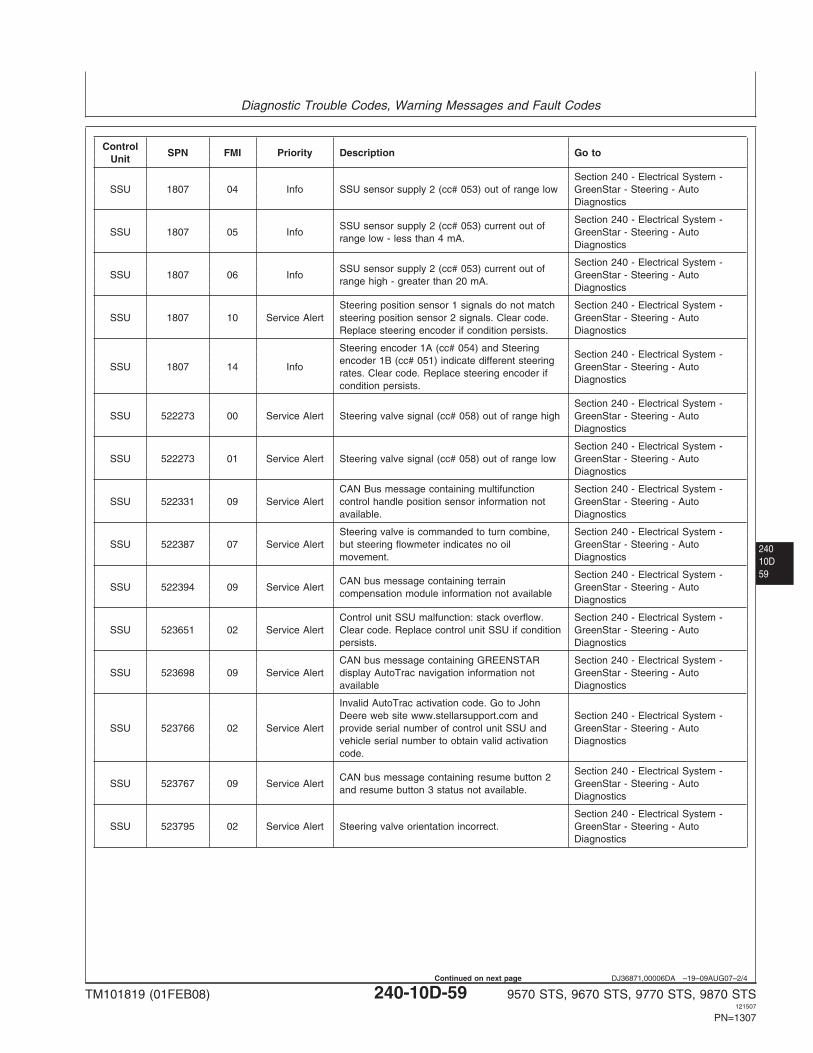
Diagnostic Trouble Codes, Warning Messages and Fault Codes
24010D59
DJ36871,00006DA –19–09AUG07–2/4
ControlSPN FMI Priority Description Go to
Unit
Section 240 - Electrical System -SSU 1807 04 Info SSU sensor supply 2 (cc# 053) out of range low GreenStar - Steering - Auto
Diagnostics
Section 240 - Electrical System -SSU sensor supply 2 (cc# 053) current out of
SSU 1807 05 Info GreenStar - Steering - Autorange low - less than 4 mA.
Diagnostics
Section 240 - Electrical System -SSU sensor supply 2 (cc# 053) current out of
SSU 1807 06 Info GreenStar - Steering - Autorange high - greater than 20 mA.
Diagnostics
Steering position sensor 1 signals do not match Section 240 - Electrical System -SSU 1807 10 Service Alert steering position sensor 2 signals. Clear code. GreenStar - Steering - Auto
Replace steering encoder if condition persists. Diagnostics
Steering encoder 1A (cc# 054) and SteeringSection 240 - Electrical System -
encoder 1B (cc# 051) indicate different steeringSSU 1807 14 Info GreenStar - Steering - Auto
rates. Clear code. Replace steering encoder ifDiagnostics
condition persists.
Section 240 - Electrical System -SSU 522273 00 Service Alert Steering valve signal (cc# 058) out of range high GreenStar - Steering - Auto
Diagnostics
Section 240 - Electrical System -SSU 522273 01 Service Alert Steering valve signal (cc# 058) out of range low GreenStar - Steering - Auto
Diagnostics
CAN Bus message containing multifunction Section 240 - Electrical System -SSU 522331 09 Service Alert control handle position sensor information not GreenStar - Steering - Auto
available. Diagnostics
Steering valve is commanded to turn combine, Section 240 - Electrical System -SSU 522387 07 Service Alert but steering flowmeter indicates no oil GreenStar - Steering - Auto
movement. Diagnostics
Section 240 - Electrical System -CAN bus message containing terrain
SSU 522394 09 Service Alert GreenStar - Steering - Autocompensation module information not available
Diagnostics
Control unit SSU malfunction: stack overflow. Section 240 - Electrical System -SSU 523651 02 Service Alert Clear code. Replace control unit SSU if condition GreenStar - Steering - Auto
persists. Diagnostics
CAN bus message containing GREENSTAR Section 240 - Electrical System -SSU 523698 09 Service Alert display AutoTrac navigation information not GreenStar - Steering - Auto
available Diagnostics
Invalid AutoTrac activation code. Go to JohnDeere web site www.stellarsupport.com and Section 240 - Electrical System -
SSU 523766 02 Service Alert provide serial number of control unit SSU and GreenStar - Steering - Autovehicle serial number to obtain valid activation Diagnosticscode.
Section 240 - Electrical System -CAN bus message containing resume button 2
SSU 523767 09 Service Alert GreenStar - Steering - Autoand resume button 3 status not available.
Diagnostics
Section 240 - Electrical System -SSU 523795 02 Service Alert Steering valve orientation incorrect. GreenStar - Steering - Auto
Diagnostics
TM101819 (01FEB08) 240-10D-59 9570 STS, 9670 STS, 9770 STS, 9870 STS121507
PN=1307
Continued on next page
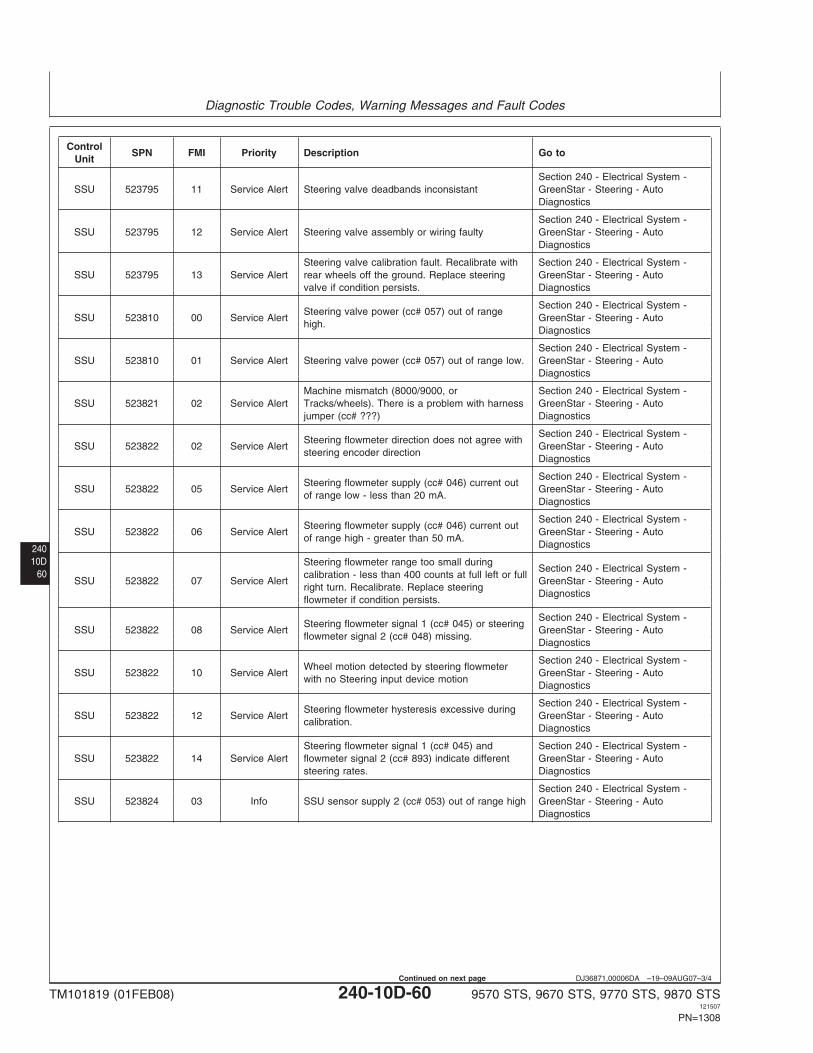
Diagnostic Trouble Codes, Warning Messages and Fault Codes
24010D
60
DJ36871,00006DA –19–09AUG07–3/4
ControlSPN FMI Priority Description Go to
Unit
Section 240 - Electrical System -SSU 523795 11 Service Alert Steering valve deadbands inconsistant GreenStar - Steering - Auto
Diagnostics
Section 240 - Electrical System -SSU 523795 12 Service Alert Steering valve assembly or wiring faulty GreenStar - Steering - Auto
Diagnostics
Steering valve calibration fault. Recalibrate with Section 240 - Electrical System -SSU 523795 13 Service Alert rear wheels off the ground. Replace steering GreenStar - Steering - Auto
valve if condition persists. Diagnostics
Section 240 - Electrical System -Steering valve power (cc# 057) out of range
SSU 523810 00 Service Alert GreenStar - Steering - Autohigh.
Diagnostics
Section 240 - Electrical System -SSU 523810 01 Service Alert Steering valve power (cc# 057) out of range low. GreenStar - Steering - Auto
Diagnostics
Machine mismatch (8000/9000, or Section 240 - Electrical System -SSU 523821 02 Service Alert Tracks/wheels). There is a problem with harness GreenStar - Steering - Auto
jumper (cc# ???) Diagnostics
Section 240 - Electrical System -Steering flowmeter direction does not agree with
SSU 523822 02 Service Alert GreenStar - Steering - Autosteering encoder direction
Diagnostics
Section 240 - Electrical System -Steering flowmeter supply (cc# 046) current out
SSU 523822 05 Service Alert GreenStar - Steering - Autoof range low - less than 20 mA.
Diagnostics
Section 240 - Electrical System -Steering flowmeter supply (cc# 046) current out
SSU 523822 06 Service Alert GreenStar - Steering - Autoof range high - greater than 50 mA.
Diagnostics
Steering flowmeter range too small duringSection 240 - Electrical System -
calibration - less than 400 counts at full left or fullSSU 523822 07 Service Alert GreenStar - Steering - Auto
right turn. Recalibrate. Replace steeringDiagnostics
flowmeter if condition persists.
Section 240 - Electrical System -Steering flowmeter signal 1 (cc# 045) or steering
SSU 523822 08 Service Alert GreenStar - Steering - Autoflowmeter signal 2 (cc# 048) missing.
Diagnostics
Section 240 - Electrical System -Wheel motion detected by steering flowmeter
SSU 523822 10 Service Alert GreenStar - Steering - Autowith no Steering input device motion
Diagnostics
Section 240 - Electrical System -Steering flowmeter hysteresis excessive during
SSU 523822 12 Service Alert GreenStar - Steering - Autocalibration.
Diagnostics
Steering flowmeter signal 1 (cc# 045) and Section 240 - Electrical System -SSU 523822 14 Service Alert flowmeter signal 2 (cc# 893) indicate different GreenStar - Steering - Auto
steering rates. Diagnostics
Section 240 - Electrical System -SSU 523824 03 Info SSU sensor supply 2 (cc# 053) out of range high GreenStar - Steering - Auto
Diagnostics
TM101819 (01FEB08) 240-10D-60 9570 STS, 9670 STS, 9770 STS, 9870 STS121507
PN=1308
Continued on next page
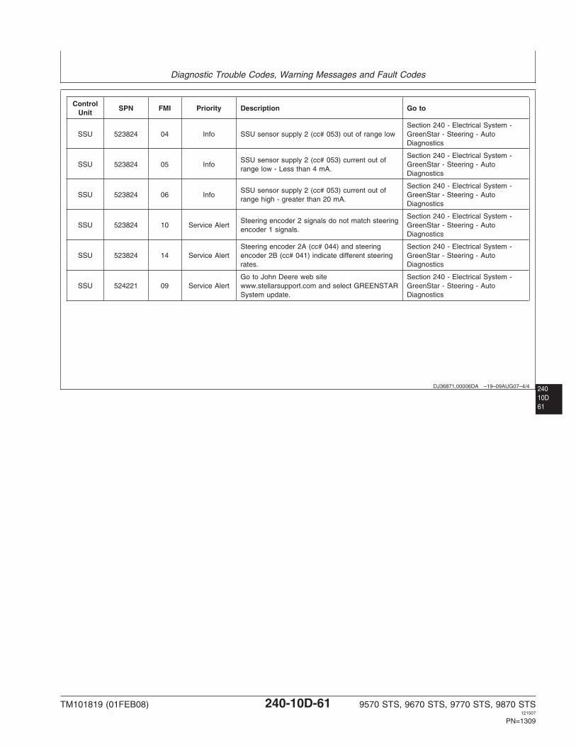
Diagnostic Trouble Codes, Warning Messages and Fault Codes
240DJ36871,00006DA –19–09AUG07–4/4
ControlSPN FMI Priority Description Go to
Unit
Section 240 - Electrical System -SSU 523824 04 Info SSU sensor supply 2 (cc# 053) out of range low GreenStar - Steering - Auto
Diagnostics
Section 240 - Electrical System -SSU sensor supply 2 (cc# 053) current out of
SSU 523824 05 Info GreenStar - Steering - Autorange low - Less than 4 mA.
Diagnostics
Section 240 - Electrical System -SSU sensor supply 2 (cc# 053) current out of
SSU 523824 06 Info GreenStar - Steering - Autorange high - greater than 20 mA.
Diagnostics
Section 240 - Electrical System -Steering encoder 2 signals do not match steering
SSU 523824 10 Service Alert GreenStar - Steering - Autoencoder 1 signals.
Diagnostics
Steering encoder 2A (cc# 044) and steering Section 240 - Electrical System -SSU 523824 14 Service Alert encoder 2B (cc# 041) indicate different steering GreenStar - Steering - Auto
rates. Diagnostics
Go to John Deere web site Section 240 - Electrical System -SSU 524221 09 Service Alert www.stellarsupport.com and select GREENSTAR GreenStar - Steering - Auto
System update. Diagnostics
10D61
TM101819 (01FEB08) 240-10D-61 9570 STS, 9670 STS, 9770 STS, 9870 STS121507
PN=1309
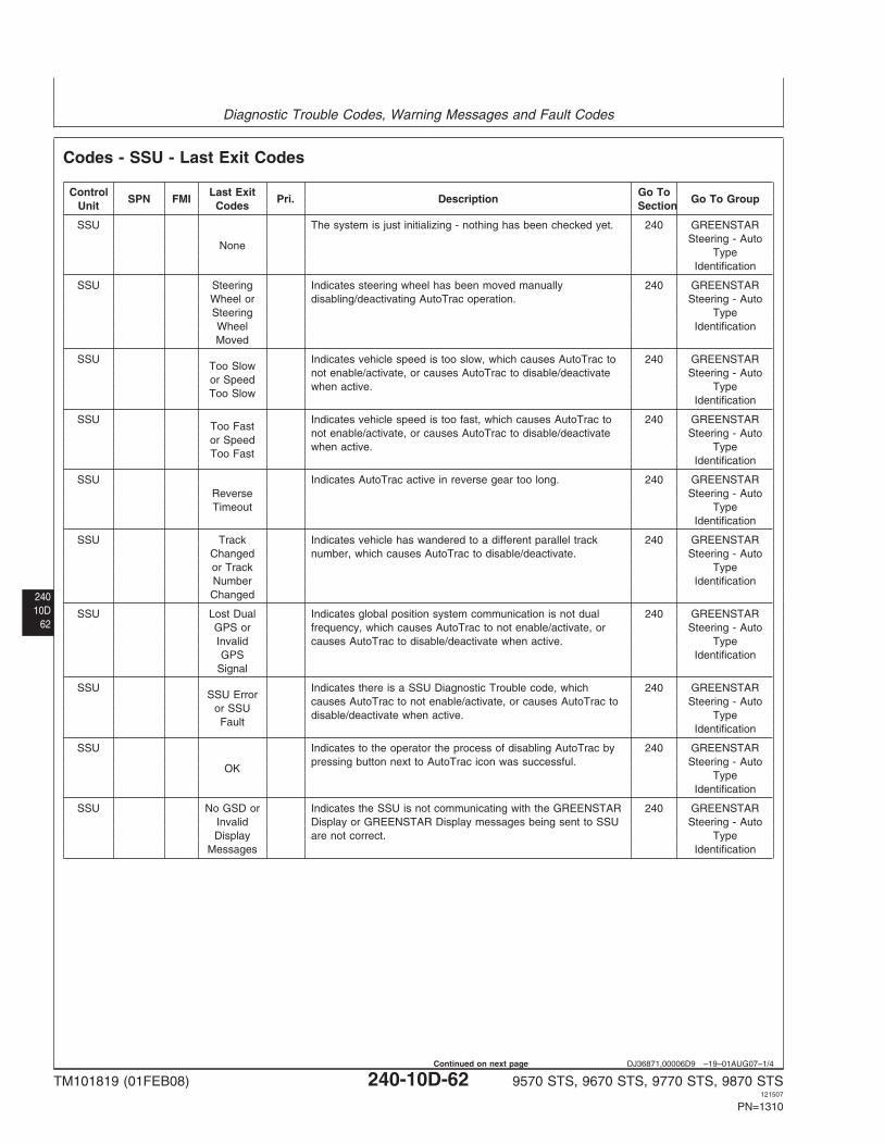
Diagnostic Trouble Codes, Warning Messages and Fault Codes
24010D
62
DJ36871,00006D9 –19–01AUG07–1/4
Codes - SSU - Last Exit Codes
Control Last Exit Go ToSPN FMI Pri. Description Go To Group
Unit Codes Section
SSU The system is just initializing - nothing has been checked yet. 240 GREENSTARSteering - Auto
NoneType
Identification
SSU Steering Indicates steering wheel has been moved manually 240 GREENSTARWheel or disabling/deactivating AutoTrac operation. Steering - AutoSteering TypeWheel IdentificationMoved
SSU Indicates vehicle speed is too slow, which causes AutoTrac to 240 GREENSTARToo Slow
not enable/activate, or causes AutoTrac to disable/deactivate Steering - Autoor Speed
when active. TypeToo Slow
Identification
SSU Indicates vehicle speed is too fast, which causes AutoTrac to 240 GREENSTARToo Fast
not enable/activate, or causes AutoTrac to disable/deactivate Steering - Autoor Speed
when active. TypeToo Fast
Identification
SSU Indicates AutoTrac active in reverse gear too long. 240 GREENSTARReverse Steering - AutoTimeout Type
Identification
SSU Track Indicates vehicle has wandered to a different parallel track 240 GREENSTARChanged number, which causes AutoTrac to disable/deactivate. Steering - Autoor Track TypeNumber IdentificationChanged
SSU Lost Dual Indicates global position system communication is not dual 240 GREENSTARGPS or frequency, which causes AutoTrac to not enable/activate, or Steering - AutoInvalid causes AutoTrac to disable/deactivate when active. TypeGPS Identification
Signal
SSU Indicates there is a SSU Diagnostic Trouble code, which 240 GREENSTARSSU Error
causes AutoTrac to not enable/activate, or causes AutoTrac to Steering - Autoor SSU
disable/deactivate when active. TypeFault
Identification
SSU Indicates to the operator the process of disabling AutoTrac by 240 GREENSTARpressing button next to AutoTrac icon was successful. Steering - Auto
OKType
Identification
SSU No GSD or Indicates the SSU is not communicating with the GREENSTAR 240 GREENSTARInvalid Display or GREENSTAR Display messages being sent to SSU Steering - AutoDisplay are not correct. Type
Messages Identification
TM101819 (01FEB08) 240-10D-62 9570 STS, 9670 STS, 9770 STS, 9870 STS121507
PN=1310
Continued on next page
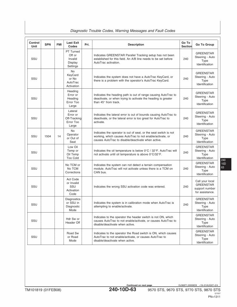
Diagnostic Trouble Codes, Warning Messages and Fault Codes
24010D63
DJ36871,00006D9 –19–01AUG07–2/4
Control Last Exit Go ToSPN FMI Pri. Description Go To Group
Unit Codes Section
PT TurnedGREENSTAR
Off or Indicates GREENSTAR Parallel Tracking setup has not beenSteering - Auto
SSU Invalid established for this field. An A/B line needs to be set before 240Type
Display AutoTrac activation.Identification
Settings
NoGREENSTAR
KeyCardIndicates the system does not have a AutoTrac KeyCard, or Steering - Auto
SSU or No 240there is a problem with the operator’s AutoTrac KeyCard. Type
AutoTracIdentification
Activation
HeadingGREENSTAR
Error or Indicates the heading path is out of range causing AutoTrac toSteering - Auto
SSU Heading deactivate, or when trying to activate the heading is greater 240Type
Error Too than 45° from track.Identification
Large
LateralGREENSTAR
Error or Indicates the lateral error is out of bounds causing AutoTrac toSteering - Auto
SSU Off-Tracking deactivate, or the lateral error is too great for AutoTrac to 240Type
Error Too activate.Identification
Large
No GREENSTARIndicates the operator is out of seat, or the seat switch is not
Operator Steering - AutoSSU 1504 14 working, which causes AutoTrac to not enable/activate, or 240
or Out of Typecauses AutoTrac to disable/deactivate when active.
Seat Identification
Low Oil GREENSTARTemp or Indicates the oil temperature is below 0°C / 32°F. AutoTrac will Steering - Auto
SSU 240Oil Temp not activate until oil temperature is above 0°C/32°F. TypeToo Cold Identification
GREENSTARNo TCM or Indicates the system can not detect a terrain compensation
Steering - AutoSSU No TCM module. AutoTrac will not activate unless there is a TCM on 240
TypeCorrections CAN bus.
Identification
Act CodeCall your local
or InvalidGREENSTAR
SSU SSU Indicates the wrong SSU activation code was entered. 240support number
Activationfor assistance.
Code
Diagnostics GREENSTARor SSU in Indicates the system is in calibration mode when AutoTrac is Steering - Auto
SSU 240Diagnostic attempting to enable/activate. Type
Mode Identification
GREENSTARIndicates to the operator the header switch is not ON, which
Hdr Sw or Steering - AutoSSU causes AutoTrac to not enable/activate, or causes AutoTrac to
Header Off Typedisable/deactivate when active.
Identification
GREENSTARRoad Sw Indicates to the operator the Road switch is ON, which causes
Steering - AutoSSU or Road AutoTrac to not enable/activate, or causes AutoTrac to
TypeMode disable/deactivate when active.
Identification
TM101819 (01FEB08) 240-10D-63 9570 STS, 9670 STS, 9770 STS, 9870 STS121507
PN=1311
Continued on next page
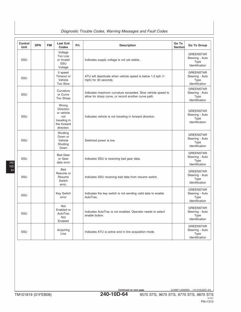
Diagnostic Trouble Codes, Warning Messages and Fault Codes
24010D
64
DJ36871,00006D9 –19–01AUG07–3/4
Control Last Exit Go ToSPN FMI Pri. Description Go To Group
Unit Codes Section
VoltageGREENSTAR
Too LowSteering - Auto
SSU or Invalid Indicates supply voltage is not yet stable..Type
SSUIdentification
Voltage
0 speed GREENSTARTimeout or ATU will deactivate when vehicle speed is below 1.5 kph (1 Steering - Auto
SSUVehicle mph) for 30 seconds. Type
Too Slow Identification
GREENSTARCurvature
Indicates maximum curvature exceeded. Slow vehicle speed to Steering - AutoSSU or Curve
allow for sharp curve, or record another curve path. TypeToo Sharp
Identification
WrongDirection
GREENSTARor vehicle
Steering - AutoSSU not Indicates vehicle is not traveling in forward direction.
Typetraveling in
Identificationthe forwarddirection.
ShuttingGREENSTAR
Down orSteering - Auto
SSU Vehicle Switched power is low.Type
ShuttingIdentification
Down
GREENSTARBad Gear
Steering - AutoSSU or Gear Indicates SSU is receiving bad gear data.
Typedata error
Identification
BadGREENSTAR
Resume orSteering - Auto
SSU Resume Indicates SSU receiving bad data from resume switch.Type
SwitchIdentification
error.
GREENSTARKey Switch Indicates the key switch is not sending valid data to enable Steering - Auto
SSUerror AutoTrac. Type
Identification
NotGREENSTAR
Enabled orIndicates AutoTrac is not enabled. Operator needs to select Steering - Auto
SSU AutoTracenable button. Type
NotIdentification
Enabled
GREENSTARAcquiring Steering - Auto
SSU Indicates ATU is active and in line acquisition mode.Line Type
Identification
TM101819 (01FEB08) 240-10D-64 9570 STS, 9670 STS, 9770 STS, 9870 STS121507
PN=1312
Continued on next page