Embed Size (px)
Citation preview
BASIC DESIGN STUDY REPORT
ON
THE PROJECT
FOR
ESTABLISHMENT OF
THE METEOROLOGICAL RADAR SYSTEM
AT MOULVIBAZAR
IN
THE PEOPLE’S REPUBLIC OF BANGLADESH
February 2007
JAPAN INTERNATIONAL COOPERATION AGENCY
JAPAN WEATHER ASSOCIATION
GM
JR
07-009
NO. Bangladesh Meteorological Department

BASIC DESIGN STUDY REPORT
ON
THE PROJECT
FOR
ESTABLISHMENT OF
THE METEOROLOGICAL RADAR SYSTEM
AT MOULVIBAZAR
IN
THE PEOPLE’S REPUBLIC OF BANGLADESH
February 2007
JAPAN INTERNATIONAL COOPERATION AGENCY
JAPAN WEATHER ASSOCIATION

PREFACE In response to a request from the Government of the People’s Republic of Bangladesh,
the Government of Japan decided to conduct a basic design study on the Project for Establishment of the Meteorological Radar System at Moulvibazar in the People’s Republic of Bangladesh and entrusted the study to the Japan International Cooperation Agency (JICA).
JICA sent to Bangladesh a study team from June 21 to July 21, 2006. The team held discussions with the officials concerned of the Government of Bangladesh,
and conducted a field study at the study area. After the team returned to Japan, further studies were made. Then, a mission was sent to Bangladesh in order to discuss a draft basic design, and as this result, the present report was finalized.
I hope that this report will contribute to the promotion of the project and to the
enhancement of friendly relations between our two countries. I wish to express my sincere appreciation to the officials concerned of the Government of
the People’s Republic of Bangladesh for their close cooperation extended to the teams.
February, 2007
Masafumi KUROKI Vice-President Japan International Cooperation Agency

February, 2007
Letter of Transmittal
We are pleased to submit to you the basic design study report on the Project for Establishment of the Meteorological Radar System at Moulvibazar in the People’s Republic of Bangladesh.
This study was conducted by Japan Weather Association, under a contract to JICA,
during the period from June, 2006 to February, 2007. In conducting the study, we have examined the feasibility and rationale of the project with due consideration to the present situation of Bangladesh and formulated the most appropriate basic design for the project under Japan's Grant Aid scheme.
Finally, we hope that this report will contribute to further promotion of the project.
Very truly yours,
Yoshihisa UCHIDA Project Manager Basic design study team on the Project for Establishment of the Meteorological Radar System at Moulvibazar in the People’s Republic of Bangladesh Japan Weather Association

Summary
S - 1
Summary Most of the area of the People’s Republic of Bangladesh (hereinafter referred to as “Bangladesh”) is a low-lying flat delta, which is the floodplains accounting for 80% of the national land formed with the alluvial soil deposited by the mighty rivers, Ganges, Brahmaputra and Meghna and 50% of the national land is 7m or less above the sea level. Bangladesh is affected seriously by devastating floods and flash floods generated by torrential rains in the pre-monsoon and monsoon seasons every year. The devastating flood and flash floods carry the highest potential for loss of life and property. In the last 15 years, 2,722 were killed or missing, 2,402,020 were injured and the number of flood victim was totally at least 78,923,331. Bangladesh is quite vulnerable to these natural disasters as the poverty in the flood plains increases due to the extensive damage in the agriculture sector. Regrettably, the extensive damage from floods and flash floods is the determining factor for significant set-back of national economy and living standard of people in Bangladesh. During the pre-monsoon season (March-May), local severe storms locally called “Nor’wester” (also known as Kalbaishakhi) occur frequently with maximum frequency in the northern part of Bangladesh. Local severe storms are the meso-scale phenomena, which develop from cumulonimbus clouds, mostly originating from neighboring India and are characterized by lightning discharges with a heavy rainfall within a short span of time. They are often accompanied with strong gusts, hail and sometimes become tornadoes. Because of the associated strong gusts and hails with short life period, these storms create hazards to river navigation, cause enormous damage to standing crops, lives and properties every year. In addition, the number of sunken vessels/ships and related casualties due to “Nor’wester” has been increasing. Disaster management system including early warning is targeted on the recognition of natural disasters such as flood, local severe storms, cyclone etc. are responsible for creating recurrent set-back on the socio-economic conditions of Bangladesh. The Project has been included in the ‘Three years Rolling Investment Program (TYRIP), Financial year 2005-2006 to 2007-2008” by the Ministry of Planning as a part of the Poverty Reduction Strategy Paper (PRSP) on the backdrop of the increasing negative impact of natural disasters, this inclusion indicated the urgent implementation of the project to minimize the economic set-back. BMD is the sole national meteorological service provider in Bangladesh and is under the administrative supervision of the Ministry of Defence. Its main responsibility as a National Meteorological Service is to record meteorological observations round the clock and to provide weather information, forecasts, advisories and warnings necessary for the mitigation and prevention of natural disasters and improvement of socio-economic conditions. Due to the present situation, Bangladesh faces the following issues.
[1] BMD is unable to provide the required precipitation data which is indispensable for preparation of

S - 2
flood forecasts and warning to the Flood Forecasting and Warning Centre (hereinafter referred to as “FFWC”) since the existing meteorological radar observation network of BMD is not able to obtain quantitative observational data of precipitation in the northern Sylhet (the wettest area in Bangladesh), the upper river basin of the Meghna and Meghalaya Hills (the world's wettest area) which are located out of the detection range of the existing network.
[2] BMD is unable to provide the required precipitation data to the FFWC and is not also able to issue
forecasts and warnings of heavy rainfall causing local rainwater flood the government and to the public for its mitigation. Because the existing Dhaka and Rangpur meteorological radar systems only can only give precipitation intensity, however, these systems do not have functional output of hydrological data required for operation of flood forecasting and warning system.
[3] FFWC is unable to issue flash flood forecasts and warnings since rainfalls in the mountainous
areas of the Indian Territory located along the international border at present are not detectable by the existing meteorological radar observation network of BMD.
[4] BMD is unable to observe Nor’wester and associated phenomena like tornadoes, these phenomena
are very short lived and occur suddenly but can caused huge damage. To mitigate the related damage and loss, prompt issuance of forecast and warning to public are needed. Due to no Doppler radar in the BMD radar network in the northern part of Bangladesh, BMD is not capable of giving prompt forecast and warning of the above devastating meteorological phenomena.
[5] The existing flood forecasting model (FE2003 Model) of Bangladesh Water Development Board
(hereinafter referred to as “BWDB”) presently runs on insufficient input data such as observe data of the existing river and rainfall information. Along with these, the longer acquisition time and lock of data over the Indian territory inhibit the accuracy improvement of flood forecasting and warnings.
In order to protect life and property from the natural disasters, it is essential to rectify the current situation as soon as possible and establish the continuous and timely dissemination of flood and local severe storm forecasts and warnings to the public and disaster management agencies. Because of financial problems, the Government of Bangladesh has requested the Government of Japan to procure and install the require equipment and to construct a radar tower building, etc. Japan’s Grant Aid Assistance. In response to the request from the Government of Bangladesh, the Government of Japan decided to conduct a Basic Design Study for the Project and consequently the Japan International Cooperation Agency (JICA) sent the Basic Design Study Team to Bangladesh from June 21, 2004 to July 21, 2006. The team had a series of discussions with Government of Bangladesh officials, conducted surveys and collected necessary information and data for the Project.
S - 3
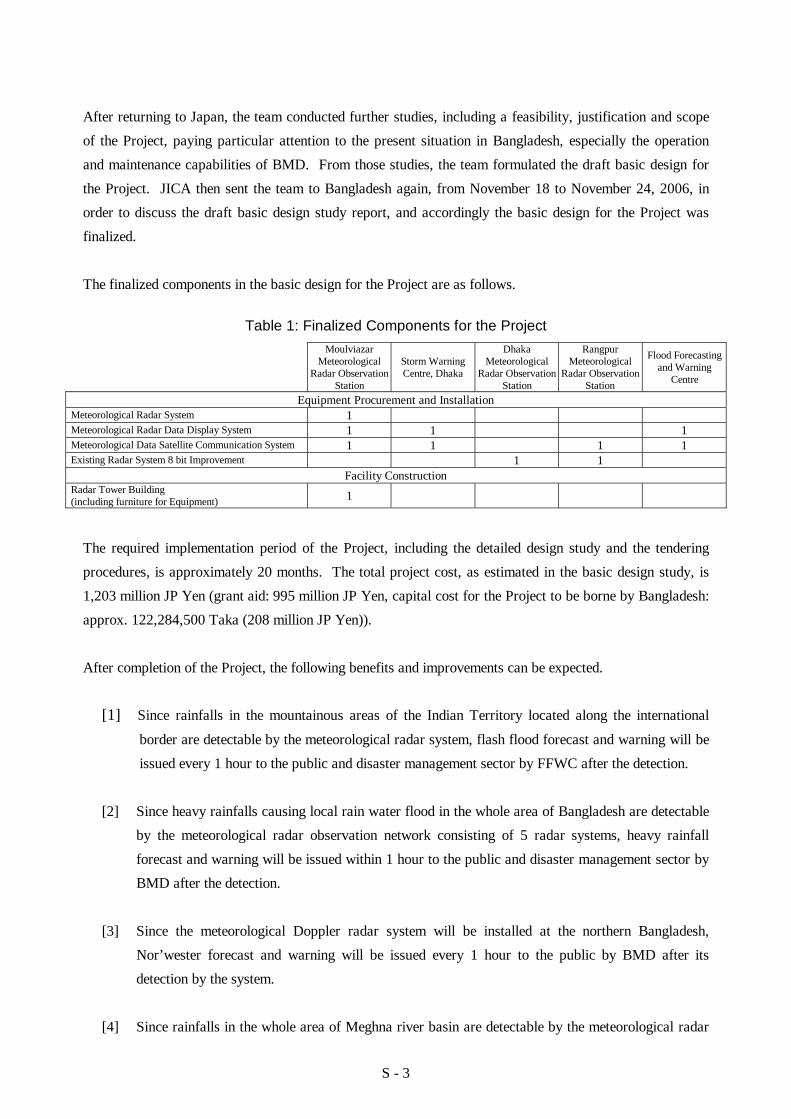
After returning to Japan, the team conducted further studies, including a feasibility, justification and scope of the Project, paying particular attention to the present situation in Bangladesh, especially the operation and maintenance capabilities of BMD. From those studies, the team formulated the draft basic design for the Project. JICA then sent the team to Bangladesh again, from November 18 to November 24, 2006, in order to discuss the draft basic design study report, and accordingly the basic design for the Project was finalized. The finalized components in the basic design for the Project are as follows.
Table 1: Finalized Components for the Project
Moulviazar Meteorological
Radar Observation Station
Storm Warning Centre, Dhaka
Dhaka Meteorological
Radar Observation Station
Rangpur Meteorological
Radar Observation Station
Flood Forecasting and Warning
Centre
Equipment Procurement and Installation Meteorological Radar System 1 Meteorological Radar Data Display System 1 1 1 Meteorological Data Satellite Communication System 1 1 1 1 Existing Radar System 8 bit Improvement 1 1
Facility Construction Radar Tower Building (including furniture for Equipment) 1
The required implementation period of the Project, including the detailed design study and the tendering procedures, is approximately 20 months. The total project cost, as estimated in the basic design study, is 1,203 million JP Yen (grant aid: 995 million JP Yen, capital cost for the Project to be borne by Bangladesh: approx. 122,284,500 Taka (208 million JP Yen)). After completion of the Project, the following benefits and improvements can be expected.
[1] Since rainfalls in the mountainous areas of the Indian Territory located along the international
border are detectable by the meteorological radar system, flash flood forecast and warning will be issued every 1 hour to the public and disaster management sector by FFWC after the detection.
[2] Since heavy rainfalls causing local rain water flood in the whole area of Bangladesh are detectable
by the meteorological radar observation network consisting of 5 radar systems, heavy rainfall forecast and warning will be issued within 1 hour to the public and disaster management sector by BMD after the detection.
[3] Since the meteorological Doppler radar system will be installed at the northern Bangladesh,
Nor’wester forecast and warning will be issued every 1 hour to the public by BMD after its detection by the system.
[4] Since rainfalls in the whole area of Meghna river basin are detectable by the meteorological radar

S - 4
system, meteorological information will be issued to the organizations concerned with disaster prevention and the public by BMD.
[5] Since precipitation data of 2.5 km mesh in the detection range of the meteorological radar
observation network can be inputted to the existing flood forecasting model (FF2003 Model), accuracy of flood forecasts and warnings will be improved.
[6] Since precipitation intensity in the detection range of the meteorological radar observation network
will be unified to be 256 gradation level indication, the rainfall observation capability will be upgraded.
BMD, the agency which will implement the Project, has quite a good organizational capability. In addition, BMD’s engineers have sufficient experience and knowledge in the operation and maintenance of meteorological radar systems to perform daily operations, maintenance and repair work on the existing systems. Furthermore, BMD’s budget is expected to be able to cover Bangladesh’s portion of the capital cost and recurrent cost of the Project. As a consequence of careful and comprehensive evaluation of the Project effects in consideration of the BMD’s capabilities in reducing human loss and recurrent economic set-back by the natural disasters, considerable benefits as mentioned above is expected to achieve. The Project would substantially contribute to the mitigation of natural disasters as the basic human needs for the people of Bangladesh, which indicate the appropriateness of carrying out the Project under a grant-aid has been amply confirmed. Therefore, the implementation of the Project is considered rightly advisable.
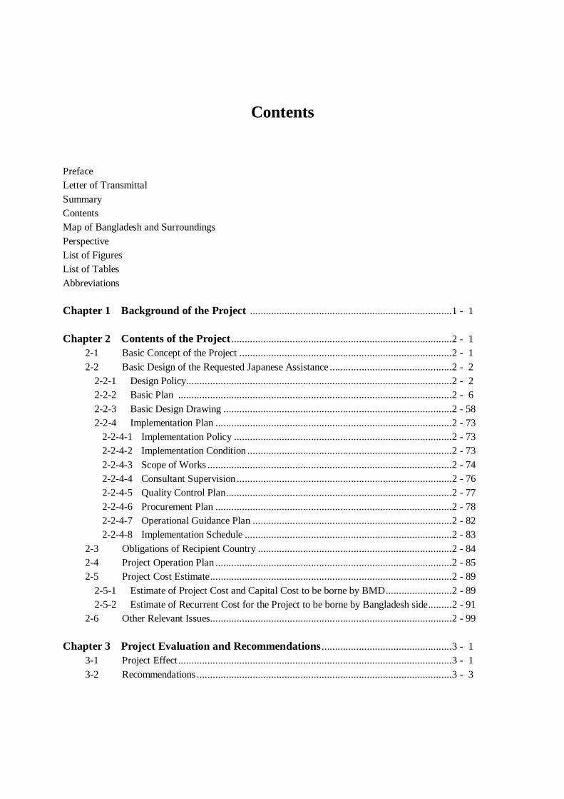
Contents
Preface Letter of Transmittal Summary Contents Map of Bangladesh and Surroundings Perspective List of Figures List of Tables Abbreviations Chapter 1 Background of the Project ............................................................................1 - 1 Chapter 2 Contents of the Project ...................................................................................2 - 1 2-1 Basic Concept of the Project ................................................................................2 - 1 2-2 Basic Design of the Requested Japanese Assistance ..............................................2 - 2 2-2-1 Design Policy....................................................................................................2 - 2 2-2-2 Basic Plan .......................................................................................................2 - 6 2-2-3 Basic Design Drawing ......................................................................................2 - 58 2-2-4 Implementation Plan .........................................................................................2 - 73 2-2-4-1 Implementation Policy ..................................................................................2 - 73 2-2-4-2 Implementation Condition .............................................................................2 - 73 2-2-4-3 Scope of Works ............................................................................................2 - 74 2-2-4-4 Consultant Supervision .................................................................................2 - 76 2-2-4-5 Quality Control Plan.....................................................................................2 - 77 2-2-4-6 Procurement Plan .........................................................................................2 - 78 2-2-4-7 Operational Guidance Plan ...........................................................................2 - 82 2-2-4-8 Implementation Schedule ..............................................................................2 - 83 2-3 Obligations of Recipient Country .........................................................................2 - 84 2-4 Project Operation Plan .........................................................................................2 - 85 2-5 Project Cost Estimate...........................................................................................2 - 89 2-5-1 Estimate of Project Cost and Capital Cost to be borne by BMD.........................2 - 89 2-5-2 Estimate of Recurrent Cost for the Project to be borne by Bangladesh side.........2 - 91 2-6 Other Relevant Issues...........................................................................................2 - 99 Chapter 3 Project Evaluation and Recommendations .................................................3 - 1 3-1 Project Effect.......................................................................................................3 - 1 3-2 Recommendations ................................................................................................3 - 3

Appendices Appendix 1. Member List of the Survey Team........................................................... APX1 - 1 Appendix 2. Study Schedule...................................................................................... APX2 - 1 Appendix 3. List of Party Concerned in the Recipient Country................................... APX3 - 1 Appendix 4. Minutes of Discussion........................................................................... APX4 - 1 Appendix 5. References ............................................................................................ APX5 - 1
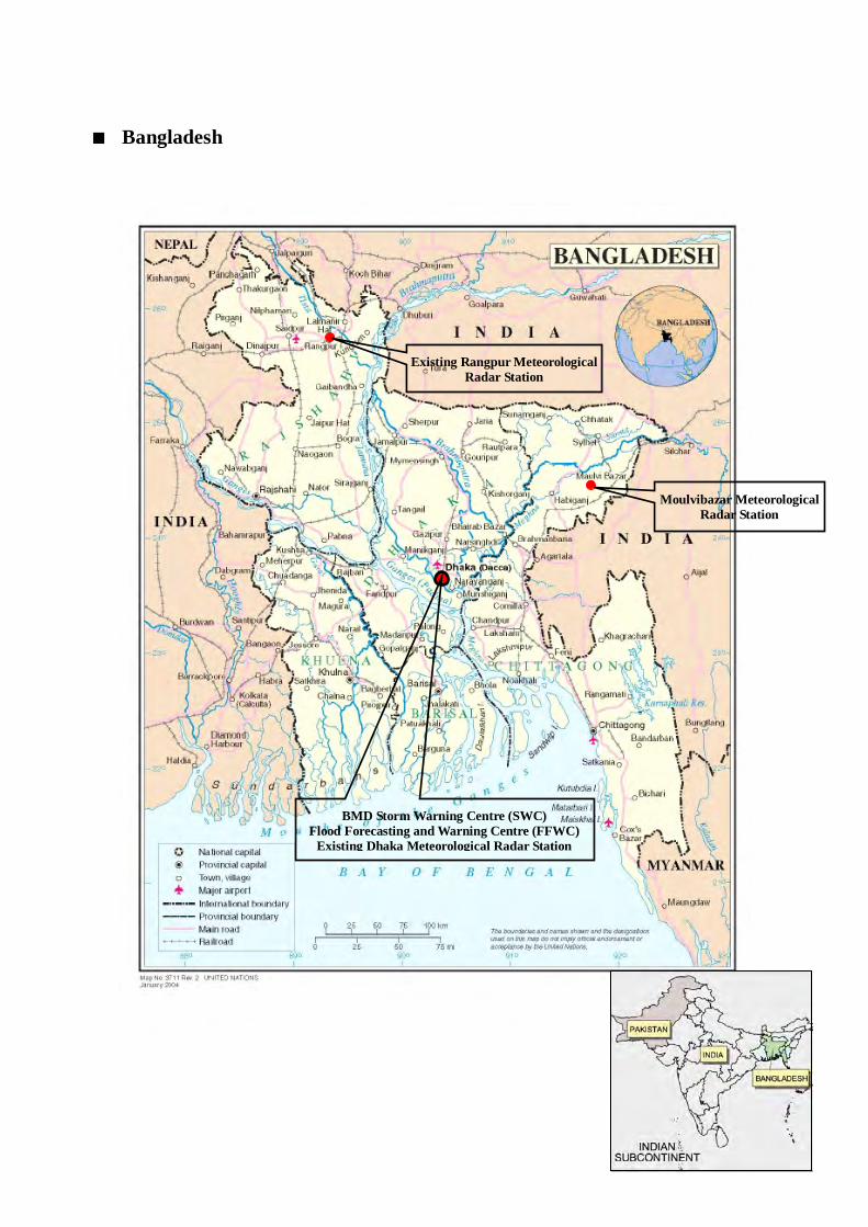
■ Bangladesh
Moulvibazar Meteorological Radar Station
BMD Storm Warning Centre (SWC) Flood Forecasting and Warning Centre (FFWC)
Existing Dhaka Meteorological Radar Station
Existing Rangpur Meteorological Radar Station
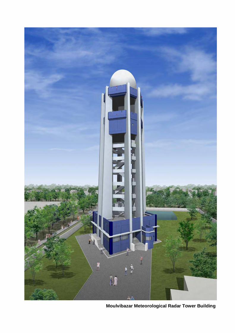
Moulvibazar Meteorological Radar Tower Building
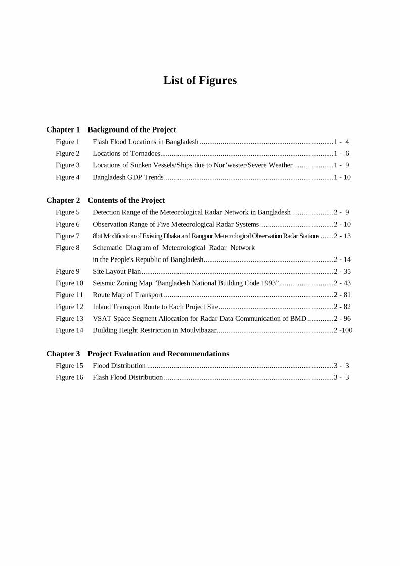
List of Figures
Chapter 1 Background of the Project Figure 1 Flash Flood Locations in Bangladesh .......................................................................1 - 4 Figure 2 Locations of Tornadoes............................................................................................1 - 6 Figure 3 Locations of Sunken Vessels/Ships due to Nor’wester/Severe Weather .....................1 - 9 Figure 4 Bangladesh GDP Trends..........................................................................................1 - 10 Chapter 2 Contents of the Project Figure 5 Detection Range of the Meteorological Radar Network in Bangladesh ......................2 - 9 Figure 6 Observation Range of Five Meteorological Radar Systems .......................................2 - 10 Figure 7 8bit Modification of Existing Dhaka and Rangpur Meteorological Observation Radar Stations .......2 - 13 Figure 8 Schematic Diagram of Meteorological Radar Network in the People's Republic of Bangladesh.....................................................................2 - 14 Figure 9 Site Layout Plan......................................................................................................2 - 35 Figure 10 Seismic Zoning Map ”Bangladesh National Building Code 1993”.............................2 - 43 Figure 11 Route Map of Transport ..........................................................................................2 - 81 Figure 12 Inland Transport Route to Each Project Site.............................................................2 - 82 Figure 13 VSAT Space Segment Allocation for Radar Data Communication of BMD ..............2 - 96 Figure 14 Building Height Restriction in Moulvibazar..............................................................2 -100 Chapter 3 Project Evaluation and Recommendations Figure 15 Flood Distribution ...................................................................................................3 - 3 Figure 16 Flash Flood Distribution ..........................................................................................3 - 3
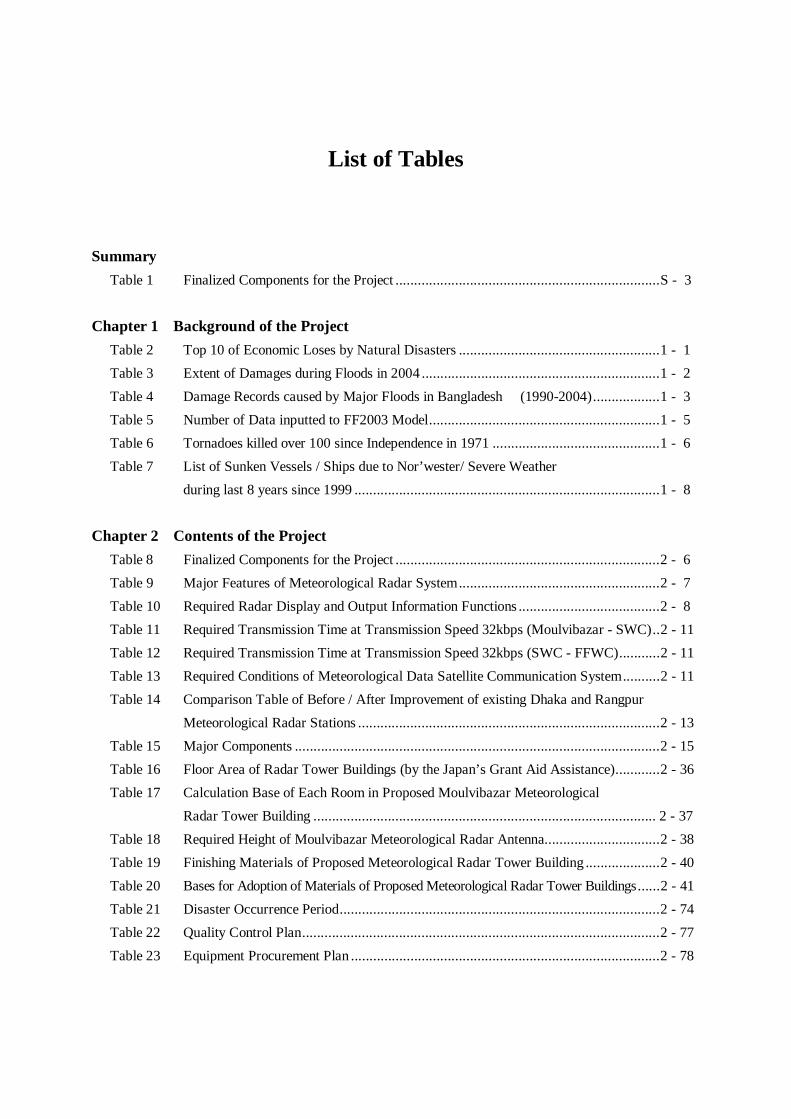
List of Tables
Summary Table 1 Finalized Components for the Project .......................................................................S - 3 Chapter 1 Background of the Project Table 2 Top 10 of Economic Loses by Natural Disasters ......................................................1 - 1 Table 3 Extent of Damages during Floods in 2004 ................................................................1 - 2 Table 4 Damage Records caused by Major Floods in Bangladesh (1990-2004)..................1 - 3 Table 5 Number of Data inputted to FF2003 Model..............................................................1 - 5 Table 6 Tornadoes killed over 100 since Independence in 1971 .............................................1 - 6 Table 7 List of Sunken Vessels / Ships due to Nor’wester/ Severe Weather during last 8 years since 1999 ..................................................................................1 - 8 Chapter 2 Contents of the Project Table 8 Finalized Components for the Project .......................................................................2 - 6 Table 9 Major Features of Meteorological Radar System......................................................2 - 7 Table 10 Required Radar Display and Output Information Functions ......................................2 - 8 Table 11 Required Transmission Time at Transmission Speed 32kbps (Moulvibazar - SWC)..2 - 11 Table 12 Required Transmission Time at Transmission Speed 32kbps (SWC - FFWC)...........2 - 11 Table 13 Required Conditions of Meteorological Data Satellite Communication System..........2 - 11 Table 14 Comparison Table of Before / After Improvement of existing Dhaka and Rangpur Meteorological Radar Stations .................................................................................2 - 13 Table 15 Major Components ..................................................................................................2 - 15 Table 16 Floor Area of Radar Tower Buildings (by the Japan’s Grant Aid Assistance)............2 - 36 Table 17 Calculation Base of Each Room in Proposed Moulvibazar Meteorological Radar Tower Building ............................................................................................ 2 - 37 Table 18 Required Height of Moulvibazar Meteorological Radar Antenna...............................2 - 38 Table 19 Finishing Materials of Proposed Meteorological Radar Tower Building ....................2 - 40 Table 20 Bases for Adoption of Materials of Proposed Meteorological Radar Tower Buildings......2 - 41 Table 21 Disaster Occurrence Period......................................................................................2 - 74 Table 22 Quality Control Plan................................................................................................2 - 77 Table 23 Equipment Procurement Plan ...................................................................................2 - 78

Table 24 Major Materials Procurement Plan (Architectural Work)..........................................2 - 80 Table 25 Major Materials Procurement Plan (Mechanical and Electrical Work) ......................2 - 81 Table 26 Operation and Maintenance Training........................................................................2 - 83 Table 27 Implementation Schedule .........................................................................................2 - 83 Table 28 Estimated Annual Radar Operation Hours................................................................2 - 85 Table 29 Required Number of Staff at Moulvibazar Meteorological Radar Station..................2 - 86 Table 30 Allocation and Recruitment Schedule of Required Engineers and Staff for Moulvibazar Meteorological Radar Station.........................................................2 - 87 Table 31 Number of Engineers and Engineering Staff in Electronic Division of BMD..............2 - 88 Table 32 Outline of Regular Inspection for the building ..........................................................2 - 88 Table 33 Life Expectancy of Building Equipment ...................................................................2 - 89 Table 34 Project Cost Estimate...............................................................................................2 - 89 Table 35 Capital Cost of BMD...............................................................................................2 - 90 Table 36 Equipment Cost of BMD .........................................................................................2 - 90 Table 37 Capital Cost of FFWC.............................................................................................2 - 90 Table 38 Recurrent Cost of Moulvibazar Radar Tower...........................................................2 - 92 Table 39 Recurrent Cost of Dhaka Radar ...............................................................................2 - 93 Table 40 Recurrent Cost of Rangpur Radar ............................................................................2 - 93 Table 41 Recurrent Cost of Dhaka Storm Warning Centre (SWC) ..........................................2 - 94 Table 42 Recurrent Cost of BMD Head Office .......................................................................2 - 94 Table 43 Recurrent Cost of Flood Forecasting and Warning Centre (FFWC)...........................2 - 94 Table 44 Recurrent Cost of Prime Minister’s Office ...............................................................2 - 95 Table 45 Recurrent Cost of Bangladesh TV Centre.................................................................2 - 95 Table 46 Recurrent Cost of Dhaka International Airport .........................................................2 - 96 Table 47 Movement of BMD Budget for Head Office.............................................................2 - 97 Table 48 Movement of BMD Budget for Radar Stations & Storm Warning Centre (SWC)......2 - 97 Table 49 BMD Budget for Moulvibazar Radar Station ...........................................................2 - 98 Table 50 Annual Budget in connection with Flood Forecasting and Warning Services in BWDB, 2005-2006..............................................................................................2 - 98 Table 51 Movement of BMD Budget for Head Office’s Space Segment ..................................2 - 99 Table 52 Required Documents for obtaining Building Construction Permission of Moulvibazar Municipality Corporation (Pourashava)...........................................2 -100 Chapter 3 Project Evaluation and Recommendations Table 53 Project Effect...........................................................................................................3 - 1 Table 54 Achievement Indicator .............................................................................................3 - 2

ABBREVIATIONS
WMO: World Meteorological Organization
ASEAN: Association of Southeast Asian Nations
JICA: Japan International Cooperation Agency
VSAT: Very Small Aperture Terminal
IEEE: Institute of Electrical and Electronic Engineers
MOD: Ministry of Defence
BMD: Bangladesh Meteorological Department
SWC: Storm Warning Centre
BDMB: Bangladesh Disaster Management Bureau
BWDB: Bangladesh Water Development Board
FFWC: Flood Forecasting and Warning Centre
BTTB: Bangladesh Telegraph and Telephone Board
BTRC: Bangladesh Telecommunication Regulatory Committee
CPTU: Central Procurement Technical Unit
TYRIP: Three Years Rolling Investment Programme
PRSP: Poverty Reduction Strategy Paper
LLDC: Least among Less Developed Countries
DANIDA: Denmark International Development Agency
UNDP: United Nations Development Program
WMIP: Water Management Improvement Project
CDMP: Comprehensive Disaster Management Program
BDRCS: Bangladesh Red Crescent Society
UNHCR: The Office of the United Nations High Commissioner for Refugees
IMD: India Meteorological Department
ECNEC: Executive Committee for National Economic Council
DPP: Development Project Proposal
JIS: Japan Industrial Standard
CPP: Cyclone Prepardness Programme
BAF: Bangladesh Air Force

Chapter 1 Background of the Project

1-1
Chapter 1 Background of the Project
Bangladesh is a disaster prone country. During the pre-monsoon, monsoon seasons and post monsoon (March-November), it is affected by tropical cyclones, storm surges, local severe storms, heavy rainfall, major floods, flash floods, etc every year. Bangladesh has long been associated with extreme vulnerability to nature disasters. Due to improvement of disaster preparedness including the establishment of early warning systems and a wide meteorological radar network, there has been a significant decrease in the number of lives lost each year. However, natural disasters are still responsible for large amount of property losses with major consequences for the poor. Areas which are prone to natural disasters are found to have higher incidences of poverty. The main reason is that natural disasters have a direct bearing on the rural economy, which has a strong linkage with agricultural production and has resulted in a seriously decreased level of living of resource-poor farmers. Among all the natural disaster’s flood itself has caused the largest economic losses. The top 10 causes of the economic losses by the natural disasters are cataloged below.
Table 2: Top 10 of Economic Loses by Natural Disasters
Natural Disaster Date of Occurrence Economic Loses (US$) 1 Flood June 20,2004 7,000,000,000 2 Flood August, 1988 2,137,000,000 3 Flood July 5, 1998 2,000,000,000 4 Cyclone April 29, 1991 1,780,000,000 5 Cyclone May15, 1995 800,000,000 6 Flood August, 1987 727,500,000 7 Flood July, 1974 579,200,000 8 Flood September, 2000 500,000,000 9 Flood July 22, 1987 330,000,000 10 Flood July 13, 1997 229,000,000
By WHO Collaborating Centre for Research on the Epidemiology of Disasters (CRED)
Emergency Events Database (EM-DAT)
<Flood and Flash Flood> Bangladesh is situated in a heavy rainfall and cyclone prone region as well as in the flood plain of major rivers which are the Ganges, the Brahmaputra and the Meghna. Three major rivers are over running the floodplains every year with huge quantity of water and discharge into the Bay of Bengal. Flooding from river waters overflowing the banks, particularly during monsoon, is an annual phenomenon. In an average year, it is estimated that over one fifth of the country goes under flood water. The people living in the low-lying flood plains have learned to adjust their life styles to this annual flooding. However, floods are still seriously harmful to development of the local industries, improvement of poverty living level, etc. Floods in Bangladesh are classified into the following four types.
Monsoon River Flood: a slow rise of water levels in the main rivers caused by heavy rainfall in the upper river basins

1-2
Flash Flood: mainly caused in the pre-monsoon season by intense heavy rainfall generated by the humid south west monsoon in the mountainous area in Indian Territory
Local Rain Water Flood: flooded by local heavy rainfall in Bangladesh
Strom Surge: a coastal phenomenon forced by cyclonic storm
Flood is an annual recurring event during the monsoon season in Bangladesh. In an average year, it is estimated that over 20% of the country goes under flood water. But the flood of 1998 was the longest ever unprecedented one in living memory and 68% of the country went under flood water. The extensive damage in the north eastern part of Bangladesh caused by the flood in 2004 was estimated much bigger than the flood in 1998. Over 38% of the country went under the flooded water and the official death toll was 747. Agricultural crops in the affected areas were fully damaged, which has primarily been estimated at 330million US dollars. In addition, the flood created the collapse of health and hygiene situation as a secondary disaster due the flood water remained for a prolonged period.
Table 3: Extent of Damages during Floods in 2004
sources: BDMB, FFWC, United Nations Human Settlements Programme
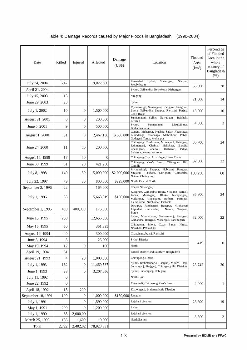
The extent of damages caused by the floods occurred in the past 15 years recorded by BDMB and FFWC is indicated in the table attached in the next page. Those floods totally created 78,923,331 victims, 2,722 dead or missing and 2,402,020 injured.
Human Suffering Physical Suffering Others
Affected population: 36,337,944 Human casualty: 747 Affected families: 7,468,128
Affected Districts: 39 Affected Upazilas: 265 Affected Unions: 2,492 Affected Area: 34,583 (Sq. km) Houses Destroyed: 151,142 Houses damaged (partially): 1,223,050 Road network destroyed: 5,000km Road network damaged: 18,400km School destroyed: 458 School damaged (partially):7,582
Death of live stock: 3,919 Crops damaged (fully): 1,605,958 (in acre) Crops damaged (partially):1,038,176 (in acre) Flooded Area:38% of the country (55,000km2)
1-3
Table 4: Damage Records caused by Major Floods in Bangladesh (1990-2004)
Date Killed Injured AffectedDamage (US$)
Location Flooded
Area (km2)
Percentage of Flooded Area in the
whole country of
Bangladesh (%)
July 24, 2004 747 19,022,600 Kanaighat, Sylhet, Sunamganj, Sherpur, Moulvibazar
April 21, 2004 Sylhet, Gaibandha, Netrokona, Kishorgonj 55,000 38
July 15, 2003 13 Siragong
June 29, 2003 23 Sylhet 21,500 14
July 1, 2002 10 0 1,500,000Mymensingh, Sunamganj, Rangpur, Kurigram, Bhola, Gaibandha, Sherpur, Rajshahi, Barisal, Cox's Bazar
15,000 10
August 31, 2001 0 0 200,000 Sunnamgonj, Sylhet, Nawabgonj, Rajshahi, Kusthia
June 5, 2001 9 0 500,000 Sylhet, Sunnamgonj, Moulvibazar, Brahamanbaria
4,000 3
August 1, 2000 31 0 2,467,138 $ 500,000 Gangni, Meherpur, Kushtia Sadar, Jibannagar, Alamdanga, Cuadanga, Maheshpur, Pabna, Godagari, Tanor, Mohanpur
June 24, 2000 11 50 200,000Chittagong, Cowkbazar, Morzapool, Katalganj, Rahmatganj, Chaktai, Halishabr, Bakalia, Chandgaon, Pahartoli, Hathazari, Patiya, Satkania, Keranirhat areas
35,700 24
August 15, 1999 17 50 0 Chittagong City, Aziz Nagar, Lama Thana
June 30, 1999 31 20 421,250 Chittagong, Cox's Bazar, Chittagong Hill, Comilla
32,000 22
July 8, 1998 140 50 15,000,000 $2,000,000 Mymensingh, Sherpur, Hobiganj, Rangpur, Sirajang, Rajshahi, Kurigram, Gaibandha, Netore, Chittagong
100,250 68
July 22, 1997 79 30 800,000 $229,000 North, Central North - -September 2, 1996 22 165,000 Chapai Nawabganj
July 1, 1996 33 5,663,319 $150,000 Kurigram, Gaibandha, Bogra, Sirajang, Tangail, Pabna, Manikganj, Dhaka, Narayanganj, Madaripur, Gopalganj, Rajbari, Faridpur, Lalmonirhat, Nilphamari Districts.
35,800 24
September 1, 1995 400 400,000 175,000Dinajpur, Panchagarh Rangpur, Nilphamari Joipurhat, Gaibandha, Natore, Naogaon, Bogra
June 15, 1995 250 12,656,006 Sylhet, Moulvibazar, Sunnamgonj, Sirajganj, Gaibandha, Rangpur, Madaripur, Panchagarh
May 15, 1995 50 351,325 Chittagong, Bhola, Cox's Bazar, Hatiya, Noakhali, Patuakhali
32,000 22
August 19, 1994 40 300,000 Chapainawabganj, Rajshahi
June 3, 1994 3 25,000 Sylhet District
May 19, 1994 12 0 100 North
April 19, 1994 61 Barisal District and Southern Bangladesh
419 0
August 21, 1993 4 20 1,000,000 Chittagong, Dhaka
July 1, 1993 162 0 11,469,537 Sylhet, Brahmanbaria, Habiganj, Moulvi Bazar, Sunamganj, Sirajganj, Chittagong Hill Districts
June 1, 1993 28 0 3,207,056 Sylhet, Sunamganj, Hobiganj
28,742 20
July 11, 1992 0 North-East
June 22, 1992 0 Maheskali, Chittagong, Cox's Bazar
April 18, 1992 15 200 Kishoreganj, Brahmambaria Districts
2,000 1
September 10, 1991 100 0 1,000,000 $150,000 Rangpur
July 1, 1991 0 1,590,000 Rajshahi division
May 1, 1991 200 0 1,200,000 Sylhet
28,600 19
July 1, 1990 65 2,000,00 Rajshahi division
March 25, 1990 166 1,600 10,000 North Eastern 3,500 2
Total 2,722 2,402,02 78,923,331
Prepared by BDMB and FFWC
1-4
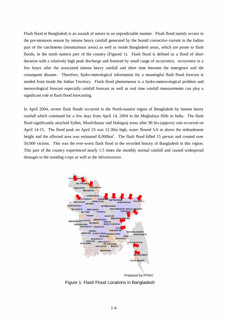
Flash flood in Bangladesh is an assault of nature in an unpredictable manner. Flsah flood mainly occure in the pre-monsoon season by intense heavy rainfall generated by the humid convective current in the Indian part of the catchments (mountainous areas) as well as inside Bangladesh areas, which are prone to flash floods, in the north eastern part of the country (Figured 1). Flash flood is defined as a flood of short duration with a relatively high peak discharge and featured by small range of occurrence, occurrence in a few hours after the associated intense heavy rainfall and short time between the emergence and the consequent disaster. Therefore, hydro-metrological information for a meaningful flash flood forecast is needed from inside the Indian Territory. Flash flood phenomenon is a hydro-meteorological problem and meteorological forecast especially rainfall forecast as well as real time rainfall measurements can play a significant role in flash flood forecasting. In April 2004, severe flash floods occurred in the North-eastern region of Bangladesh by intense heavy rainfall which continued for a few days from April 14, 2004 in the Meghalaya Hills in India. The flash flood significantly attacked Sylhet, Moulvibazar and Habiganj areas after 96 hrs.(approx) rain occurred on April 14-15. The flood peak on April 23 was 12.30m high, water flowed 5-6 m above the embankment height and the affected area was estimated 8,000km2. The flash flood killed 15 person and created over 50,000 victims. This was the ever-worst flash flood in the recorded history of Bangladesh in this region. This part of the country experienced nearly 1.5 times the monthly normal rainfall and caused widespread damages to the standing crops as well as the infrastructure.
Figure 1: Flash Flood Locations in Bangladesh
Prepared by FFWC

1-5
Meghalaya Hills Border Line
North-eastern region of Bangladesh
For the flash flood forecast another important parameter is the rainfall estimation. However, since the meteorological radar observation network of BMD unfortunately do not cover the northern Sylhet, the Meghna upper river basin and Meghalaya Hills and also BMD only receives precipitation data of 7 synoptic stations located in the Meghna upper river basin in Indian Territory thorough the Global Telecommunication System (GTS) of World Meteorological Organization (WMO), BMD has no precipitation distribution data in those areas. In addition to this, the existing Dhaka and Rangpur radar systems can output precipitation intensity, however, these systems are not capable to output the following hydrological data required for flood forecasting. In fact, these situations indicated above disturb accuracy improvement of flood forecasts and warnings.
• PPI (Plan Position Indicator) Display • Heavy Rainfall Warning Output • Accumulated Rainfall • Rainfall Distribution • Catchment Area Rainfall Amount Display and Warning
Furthermore, insufficiency of data observed at the existing river and rainfall stations of BWDB for inputting to the existing flood forecasting model (FF2003 Model), longer acquisition time of the required data and lack of data in the Indian Territory inhibit accuracy improvement of flood forecasts and warnings prepared by the existing flood forecasting model (FF2003 Model) of FFWC.
Table 5: Number of Data inputted to FF2003 Model
River Basin River Station Rainfall Station Ganges Basin 29 17
Brahmaputra Basin 23 13 Meghna Basin 22 15
South Eastern Hill Basin 12 11 Total 86 56
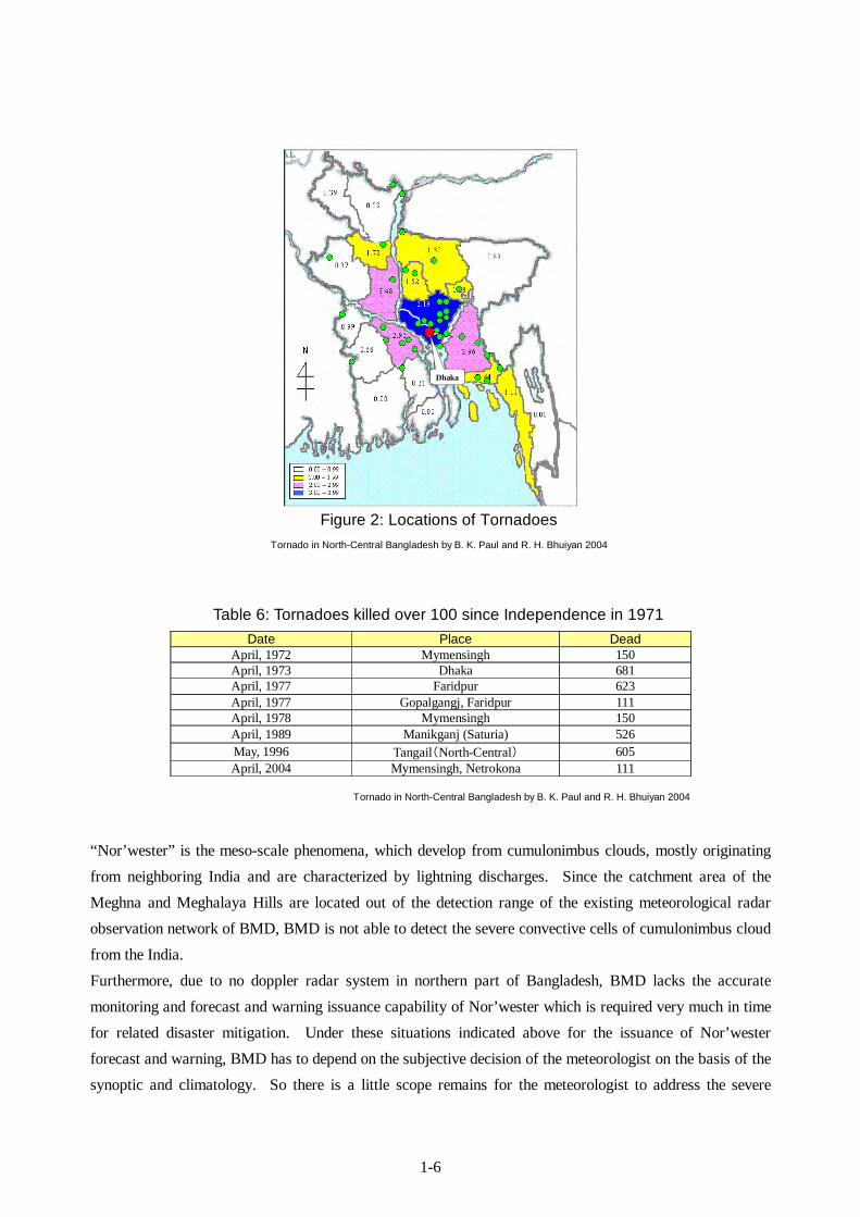
< Nor’wester and Tornado> During the pre-monsoon season (March-May), local severe storms locally called “Nor’wester” (also known as Kalbaishakhi) sometimes associated with tornadoes, occur frequently with maximum frequency in the northern part of Bangladesh. Tornado occur intensively in March (8%), April (36%) and May (22%) mainly in the central and northern areas of Bangladesh. For 30 years between 1967 and 1996, 191 tornadoes occurred and totally killed 5,373 people and frequency of the occurrence is increasing.
1-6
Table 6: Tornadoes killed over 100 since Independence in 1971
Tornado in North-Central Bangladesh by B. K. Paul and R. H. Bhuiyan 2004
“Nor’wester” is the meso-scale phenomena, which develop from cumulonimbus clouds, mostly originating from neighboring India and are characterized by lightning discharges. Since the catchment area of the Meghna and Meghalaya Hills are located out of the detection range of the existing meteorological radar observation network of BMD, BMD is not able to detect the severe convective cells of cumulonimbus cloud from the India. Furthermore, due to no doppler radar system in northern part of Bangladesh, BMD lacks the accurate monitoring and forecast and warning issuance capability of Nor’wester which is required very much in time for related disaster mitigation. Under these situations indicated above for the issuance of Nor’wester forecast and warning, BMD has to depend on the subjective decision of the meteorologist on the basis of the synoptic and climatology. So there is a little scope remains for the meteorologist to address the severe
Dhaka
Figure 2: Locations of Tornadoes Tornado in North-Central Bangladesh by B. K. Paul and R. H. Bhuiyan 2004
Date Place Dead April, 1972 Mymensingh 150 April, 1973 Dhaka 681 April, 1977 Faridpur 623 April, 1977 Gopalgangj, Faridpur 111 April, 1978 Mymensingh 150 April, 1989 Manikganj (Saturia) 526 May, 1996 Tangail(North-Central) 605 April, 2004 Mymensingh, Netrokona 111

1-7
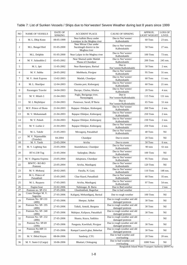
weather phenomena accurately and timely which greatly undermines the required attention and consideration for safe operation and movement of river vessels by the owner. The number of sunken vessels/ships has been increasing in current years. 34 vessels/ships were sunken and 958 passengers were killed by “Nor’wester” or severe weather during last 8 years since 1999.
1-8
Table 7: List of Sunken Vessels / Ships due to Nor’wester/ Severe Weather during last 8 years since 1999
NO NAME OF VESSELS DATE OF SINKING ACCIDENT PLACE CAUSE OF SINKING APPROX.
LIGHT WEIGHTLOSS OF
LIVES
1 M. L. Dhip Konn 08-05-1999 Near kalkini Buoy under Laxmipur in the Meghna river
Due to Nor’wester/ Kalboishakhi 60 Tons 23 nos.
2 M.L. Bengal Bird 01-05-2000 Near Mirzar Char under Narshingdi district in the
Meghna river
Due to Nor’wester/ Kalboishakhi 50 Tons 27 nos.
3 M.L. Dolphin 01-05-2000 Near Lalpur in the Meghna river Due to Nor’wester/ Kalboishakhi 100 Tons 73 nos.
4 M. V. Salauddin-2 03-05-2002 Near Shatnal under Matlab Thana of Chandpur
Due to Nor’wester/ Kalboishakhi 200 Tons 245 nos.
5 M. L. Ipti 11-05-2002 Near Banoripara, Barisal Due to Nor’wester/Kalboishakhi 50 Tons 2 nos.
6 M. V. Subha 24-05-2002 Motbbaria, Pirojpur Due to Nor’wester/ Kalboishakhi 95 Tons 31 nos.
7 M. V. Amit Express 13-02-2003 Matlab, Chandpur Due to Nor’wester/ Kalboishakhi 60 Tons 11 nos.
8 M. L. Sharifpur 12-04-2003 Chamta port, Kishorganj Due to Nor’wester/ Kalboishakhi 60 Tons 21 nos.
9 Passengers Trawler 14-04-2003 Dacope, Chalna, Khulna Due to Nor’wester/ Kalboishakhi 20 Tons 4 nos.
10 M. V. Mitali-3 21-04-2003 Pagla, Buriganga river, Narayanganj
Due to Nor’wester/Kalboishakhi 115 Tons 131 nos.
11 M. L Majlishpur 21-04-2003 Paneswar, Sarail, B’Baria Due to Nor’wester/Kalboishakhi 65 Tons 51 nos
12 M.V. Prince of Ekata 21-04-2003 Rajapur- Dilalpur, Kishorganj Due to Nor’wester/ Kalboishakhi 260 Tons 2 nos.
13 M. V. Mohammadi 21-04-2003 Rajapur Dilalpur, Kishorganj Due to Nor’wester/ Kalboishakhi 250 Tons 2 nos.
14 M. V. Palash 21-04-2003 Rajapur Dilalpur, Kishorganj Due to Nor’wester/ Kalboishakhi 230 Tons 2 nos.
15 M. V. Lutfar-2 21-04-2003 Rajapur Dilalpur, Kishorganj Due to Nor’wester/ Kalboishakhi 250 Tons 2 nos.
16 M. L. Takdir 21-05-2003 Mirzagonj, Patuakhail Due to Nor’wester/ Kalboishakhi 40 Tons Nil
17 M. V. Nijamuddin (Trawler) 04-2004 Chandpur Due to storm 20 Tons Nil
18 M. V. Tanik 23-05-2004 Aricha Due to storm 50 Tons 6 nos.
19 M. V. Lighting Sun 23-05-2004 Anandabazar, Chandpur Due to Nor’wester/ Kalboishakhi 90 tons 61 nos
20 BT-6-238 Tug 21-05-2004 Sadarghat, Dhaka Due to Nor’wester/ Kalboishakhi 100 Tons Nil
21 M. V. Diganta Express 23-05-2004 Jahajmara, Chandpur Due to Nor’wester/ Kalboishakhi 95 Tons 25nos
22 BIWTC- RO-RO Pontoon 23-05-2004 Aricha, Manikganj Due to Nor’wester/
Kalboishakhi 120 Tons Nil
23 M. V. Moharaj 20-02-2005 Fatulla, N. Ganj Due to Nor’wester/ Kalboishakhi 110 Tons 148 nos.
24 M. L. Prince of Patuakhali 15-05-2005 Char Kazol, Patuakhali Due to Nor’wester/
Kalboishakhi 60 Tons 35 nos.
25 M. L. Raypura 17-05-2005 Aricha, Manikganj Due to Nor’wester/ Kalboishakhi 97 Tons 54 nos.
26 Engine boat 22-02-2006 Nabinagar, B. Baria Due to Bad weather - 2 nos 27 Pontoon no. SP-151 27-05-2006 Ghashiakhali, Bagerhat Due to bad weather - -
28 Crane Dredger M. V. Sagorika 27-05-2006 Kaliganj, Mehandiganj, Barisal Due to rough weather 100 Tons Nil
29 Pontoon No- SP-133 (48ft) 27-05-2006 Sherpur, Sylhet Due to rough weather and old
damaged pontoon 30 Tons Nil
30 Pontoon No- SP- 195 (48ft) 27-05-2006 Taltali, Amtali, Barguna Due to rough weather and old
damaged pontoon 30 Tons Nil
31 Pontoon No. SP- 240 (48ft) 27-05-2006 Mahipur, Kalipura, Patuakhali Due to rough weather and old
damaged pontoon 30 Tons Nil
32 Pontoon No- SP- 232 (48ft) 27-05-2006 Shanta, Koyra, Satkhira Due to rough weather and old
damaged pontoon - Nil
33 Pontoon No- SP-69 (30ft) 27-05-2006 Pangasia, Kawkhali, Pirojpur Due to rough weather and old
damaged pontoon 30 Tons Nil
34 Pontoon No-MP-31 (64ft) 27-05-2006 Rampal Launch ghat, Beherhat Due to rough weather and old
damaged pontoon 30 Tons Nil
35 M. V. IMrul Kayes 08-06-2006 Sandwip, CTG Due to bad weather and overloading 20 Tons 20 nos.
36 M. V. Sumi-3 (Cargo) 10-06-2006 Bhatiari, Chittagong Due to bad weather and overloading 1000 Tons Nil
Bangladesh Inland Water Transport Authority (BIWTA)
1-9
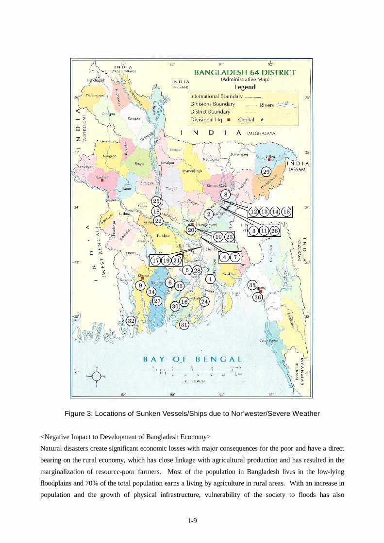
Figure 3: Locations of Sunken Vessels/Ships due to Nor’wester/Severe Weather
<Negative Impact to Development of Bangladesh Economy> Natural disasters create significant economic losses with major consequences for the poor and have a direct bearing on the rural economy, which has close linkage with agricultural production and has resulted in the marginalization of resource-poor farmers. Most of the population in Bangladesh lives in the low-lying floodplains and 70% of the total population earns a living by agriculture in rural areas. With an increase in population and the growth of physical infrastructure, vulnerability of the society to floods has also
36
3534
33
32 31
30
29
28
27
25
24
2220
18
16
9
8
15 14 1312
2310
6
5
2
1
4 717 19 21
3 11 26
1-10
increased. Since most of the total population engaged in agriculture accounting for 21% of GDP, the industrial structure of Bangladesh is quite vulnerable to natural disasters such as floods, flash floods, local severe storms, etc. Consecutive floods at times drastically reduce the GDP growth rate.
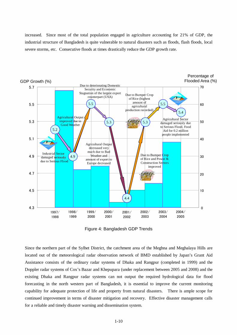
Figure 4: Bangladesh GDP Trends
Since the northern part of the Sylhet District, the catchment area of the Meghna and Meghalaya Hills are located out of the meteorological radar observation network of BMD established by Japan’s Grant Aid Assistance consists of the ordinary radar systems of Dhaka and Rangpur (completed in 1999) and the Doppler radar systems of Cox’s Bazar and Khepupara (under replacement between 2005 and 2008) and the existing Dhaka and Rangpur radar systems can not output the required hydrological data for flood forecasting in the north western part of Bangladesh, it is essential to improve the current monitoring capability for adequate protection of life and property from natural disasters. There is ample scope for continued improvement in terms of disaster mitigation and recovery. Effective disaster management calls for a reliable and timely disaster warning and dissemination system.
4.9
5.5
5.3
4.4
5.3
5.5
5.4
5.2
4.3
4.5
4.7
4.9
5.1
5.3
5.5
5.7
1997/
1998
2004/
2005
2003/
2004
2002/
20032001/
2002
2000/
2001
1999/
2000
1998/
1999
70
50
40
30
20
10
0
60
GDP Growth (%) Percentage of
Flooded Area (%) Due to deteriorating Domestic
Security and Economic Stagnation of the largest export
counterpart (USA) Due to Bumper Crop of Rice (highest
amount of agricultural
production recorded)
Agricultural Output improved due to Good Weather
Due to Bumper Crop of Rice and Power & Construction Sectors
improved
Agricultural Output decreased very
much due to Bad Weather and
amount of export to Europe decreased
Industrial Sector damaged seriously
due to Serious Flood
Agricultural Sector damaged seriously due to Serious Flood, Food
Aid for 0.2 million people implemented
5.2
5.5
5.3 5.3
4.9
4.4
5.5
5.4
1-11
In order to provide continuous and timely monitoring, dissemination and issuance of accurate forecasts and warnings of local severe storms (Nor’westers), tornadoes, floods, flash floods to the public, due to local financial constraints, the Government of Bangladesh requested the Government of Japan to realize the following components using Japan’s Grant Aid Assistance. <Equipment>
[1] Procurement and Installation of Meteorological Doppler Radar System (S-band)
[2] Procurement and Installation of Communication System for Data Transmission
<Facilities>
[3] Construction of Radar Tower Building in the premises of BWDB in Moulvibazar (the ownership
of the site has been scheduled to transfer from BWDB to BMD)
As a consequence of the several discussions with BMD and FFWC during the Basic Design Study in Bangladesh, the following components were additionally requested by Bangladesh side to be included in the Project for generating wider project effects effectively.
<Equipment>
[4] Existing Dhaka and Rangpur Meteorological Radar System 8 bit Improvement
[5] Procurement and Installation of Meteorological Radar Data Display Systems for Prime Minister
Office, Bangladesh TV Centre and Dhaka International Airport It was agreed that in accordance with the project implementation schedule, the project component of [5]
mentioned above will be procured by BMD as self-reliant efforts of Bangladesh.

Chapter 2 Contents of the Project

2-1
Chapter 2 Contents of the Project 2-1 Basic Concept of the Project Bangladesh is affected seriously by devastating floods, flash floods and local severe storms every year which have created disaster-stricken tens of millions people. Regrettably, these disasters have caused significant damage to agriculture as the essential industry of Bangladesh and inflicted suffering on the poverty. The extensive damage from these disasters is the determining factor for significant set-back of national economy and living standard of the poverty in Bangladesh. Because of the situations indicated above, establishment of disaster management system including early warning is targeted for further reduction of damages created by natural disasters indicated in the Poverty Reduction Strategy Paper 2005. According to the Paper, the Project aims at upgrading the early-warning information such as accuracy improvement of flood forecasts, timely issuance of flash flood forecasts, and quick issuance of local severe storms and torrential rain through real-time acquisition of i) the precipitation in the whole area of Bangladesh, upper river basins in Indian Territory and mountainous areas located along the international border, ii) actual location of local severe storms and torrential rains; and iii) accumulated rainfall. Devastating floods and flash floods are generated by torrential rains in the mountainous areas and the upper river basins of the Indian Territory. Local rain water floods are generated by local heavy rainfall in Bangladesh. In addition, local severe storms are developed from cumulonimbus clouds mostly originating from India and sometimes accompanied with tornadoes. In order to accomplish the target indicated above for reduction of damages created by the natural disasters, establishment of the required equipment and facilities will be implemented in the Project, which makes the followings possible.
• estimation of flooded water volume flowing in Bangladesh from India through monitoring rainfall in the upper river basins
• acquisition of precipitation in the mountainous areas of the Indian side, and • acquisition of precipitation in the whole area of Bangladesh
Due to the establishment of the required equipment and facilities mentioned above,
① Issuance of a flash flood forecast and warning every 1 hour after detection of heavy rainfall by a meteorological radar system,
② Issuance of a local severe storm forecast and warning every 1 hour after detection of local severe storm by a meteorological radar system,
③ Issuance of a rainfall forecast and warning causing local rain water flood within 1 hour after detection of heavy rainfall by a meteorological radar system, and

2-2
④ Accuracy improvement of flood forecasts and warnings, are expected. The planned project components are construction of a radar tower building and installation of a meteorological radar system in Moulvibazar, existing Dhaka and Rangpur radar systems 8 bit improvement, installation of meteorological data display systems at SWC and FFWC, and establishment of meteorological data satellite communication systems connecting each project site.
2-2 Basic Design of the Requested Japanese Assistance 2-2-1 Design Policy (1) Basic Policy for the Basic Design of the Project
a) To design a meteorological observation system to contribute to disaster prevention. b) To enable BMD to contribute effectively to the protection of people’s life and property for
sustainable socioeconomic activities. c) To enable BMD to monitor weather condition round-the-clock on a real time basis. d) To enable BMD and FFWC to issue meteorological and hydrological information and
forests/warnings to the public promptly. e) To set up the size and components of the Project to match the technical, operational and
maintenance capabilities of BMD.
(2) Design Policy [1] Design Policy of the Equipment
a) To design the system so that it is within BMD’s capability to operate, maintain and repair. b) To ensure the equipment is compatible with and meets the technical requirements of the World
Meteorological Organization (WMO). c) To ensure the equipment is suitable for the routine observation and forecasting work of BMD. d) To select equipment for which spare parts and consumables can be easily procured and replaced. e) To select reliable and durable equipment suitable for the local environment. f) To minimize the recurrent costs to BMD of the operation, maintenance and repair of the
equipment. g) To design the equipment by adjusting the accuracy of radar data through calibration. h) To design the equipment to minimize lightning damage.

2-3
i) To design the equipment to operate using 420V±20%, 3 Phase, 50Hz or 220V±20% Single Phase, 50Hz, power.
[2] Design Policy of Radar Tower Building
The design policy is to create a building suitable for use as meteorological radar facility and to become an operational base for weather observation. The plan is to construct meteorological radar tower buildings that will ensure appropriate and effective operations and will accommodate the required systems, equipment and personnel. It is a basic policy that the designed Radar Tower Buildings satisfy the following requirements.
a. To be capable of carrying out a variety of meteorological services as the "Radar Tower
Buildings." b. To provide the necessary environment for meteorological work to be performed effectively and
efficiently. c. To be suitable for BMD’s 24hours/day work schedule of observations. d. To have the necessary power supply back-up equipment (diesel generator, radar power backup
unit, auto voltage regulator, etc.) for performing round-the-clock meteorological services 24 hours a day, 365 days a year.
e. To be sufficiently robust to withstand extreme weather and permit the performance of uninterrupted radar observation and the supply of weather forecast & warnings, even during a natural disaster.
f. To be suitable for the installation of a Doppler radar systems and other related equipment supplied under the Project.
g. To make use of local building materials for easy maintenance of the radar tower buildings by BMD.
(3) Design Policy on Environmental Conditions
1) Temperature Air-conditioning systems are required for rooms where the equipment is to be installed since Moulvibazar has a high temperature and high humid climate.
2) Rainfall The maintenance stair-case has been located at the center of the building, covered by the upper concrete slab, to enable BMD personnel to easily reach each room for regular maintenance of the radar equipment without getting wet during the Pre-monsoon, Monsoon and Post-monsoon seasons (April-October). These are the busiest periods for the radar system.
2-4
3) Flood Moulvibazar is located in the high risk area of floods and flash foods. Therefore, the ground floor of the radar tower building will be built high enough to minimize any damage by floods/flash foods.
4) Lightning The frequent lightning occurs especially during the rainy season. A lightning protector is, therefore planned, to prevent damage to the building and to the equipment. 5) Local Severe Storm To ensure highly accurate radar observations, the maximum horizontal movement angle of the building must be not more than 0.085 degree (5% of the designed radar beam angle) during a local sever storm.
6) Earthquake According to the “Bangladesh National Building Code 1993”, Moulvibazar is located in “Zone 3”. The “Basic Seismic Coefficient” of each zone indicated in the Code will be incorporated into the structural design and calculation for the radar tower building. 7) Load Bearing Layer The suitable load bearing layer (silty, clayey gravel with sand) for the building construction (N value: 50) has been found at a depth of approximately 47m. To prevent differential settlement, cast-in-place concrete piles penetrating at least 0.5-1m into the load bearing layer will be used.
(4) Design Policy for Construction Work
1) Environmental Regulation Environmental restrictions will not be applied for construction of the radar tower building because the construction work of the Project is not large-scale. However, there must be appropriate consideration given to protecting the environment surrounding the sites of the construction work. Waste water discharged from the radar tower building must undergo initial treatment before filtering treatment into the soil at each site.
2) Use of Locally Procurable Materials Gravel, sand, cement, blocks, bricks, floor materials, reinforced bars, etc. are produced in Bangladesh while other construction materials are imported from ASEAN (Association of Southeast Asian Nations) countries. Most of the construction materials are procurable in the local market. For the Project, durable maintainable materials will be selected from the locally procurable materials. 3) Use of Local Construction Methods and Local Workers The common local construction method involves Reinforced Concrete (RC) columns, beams and slabs
2-5
and concrete block walls, with a mortar trowel and paint finish. For the Project, this method will be used. Laborers are classified by their skills, such as carpenters, plasterers, steel fitters, etc. However, there is currently a shortage of skilled laborers and the skill level is variable in Bangladesh. In order to utilize local laborers as much as possible, local construction methods with which local workers are familiar will be used.
(5) Policy for Use of Local Construction Companies
Generally in Bangladesh, the technical skills and competence of the major local construction companies are adequate, so they will effectively be used in construction of the radar tower building.
(6) Design Considerations to Simplify Operation and Maintenance for BMD
1) Easy to operate the equipment The equipment to be supplied under the Project is to be used to support BMD’s routine works as the national meteorological agency for the meteorological disaster prevention. A variety of data processing, analysis, display and communications capabilities must be readily available for BMD, using simple operational procedures.
2) Easy maintenance and affordable recurrent costs of the equipment The equipment must be designed to minimize the spare parts and consumables required and to simplify regular maintenance. Replacement parts must be quickly and readily available. The biggest recurrent cost of the Project is expected to be electricity, therefore the equipment and facilities should be designed to minimize power consumption.
3) Consideration of minimizing operation & maintenance costs In order for BMD to meet the increased ongoing costs of the system, such as operation and maintenance costs, after the completion of the Project, the following measures have been included in planning for the equipment and the radar tower building.
• The ability to restrict the operation of air-conditioning systems and the electricity supply to the
operational rooms in the radar tower building • The utilization of natural light to reduce energy requirements by minimizing the hours of artificial
lighting required. • The incorporation of solid-state parts into the radar system as much as possible to reduce the cost
and frequency of parts replacement.
2-6
(7) Design Policy for Equipment & Building Grade To allow the supply of uninterrupted forecasts and warnings to the public, even during occurrence of a natural disaster, the equipment and building must be sufficiently robust to withstand floods, local severe storms and lightning strikes and enable the provision of meteorological services 24 hours per day. (8) Design Policy regarding Construction/Procurement Method and Schedule
Locally procurable materials and the local construction methods must be used in the building design. The equipment to be installed in the radar tower building, such as specialized power backup systems and meteorological equipment, which is not available in the local market, will be mainly procured from Japan. This equipment must be durable, reliable, of a high technical level, and cost effective. Where possible, outside installation work should not be carried out during the monsoon season (rainy season), which, in Sylhet, is between April and September. Examples of this work include the radar antenna, radome, etc., which will be installed on the top of the radar tower building. In addition, installation of the radar system must also be completed in the dry season to avoid damage from rainwater.
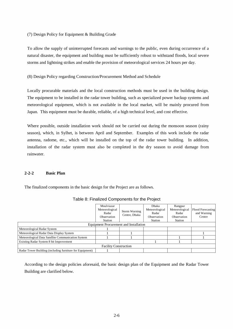
2-2-2 Basic Plan The finalized components in the basic design for the Project are as follows.
Table 8: Finalized Components for the Project
Moulviazar Meteorological
Radar Observation
Station
Storm Warning Centre, Dhaka
Dhaka Meteorological
Radar Observation
Station
Rangpur Meteorological
Radar Observation
Station
Flood Forecasting and Warning
Centre
Equipment Procurement and Installation Meteorological Radar System 1 Meteorological Radar Data Display System 1 1 1 Meteorological Data Satellite Communication System 1 1 1 1 Existing Radar System 8 bit Improvement 1 1
Facility Construction Radar Tower Building (including furniture for Equipment) 1
According to the design policies aforesaid, the basic design plan of the Equipment and the Radar Tower Building are clarified below.
2-7
(1) Basic Plan of the Equipment
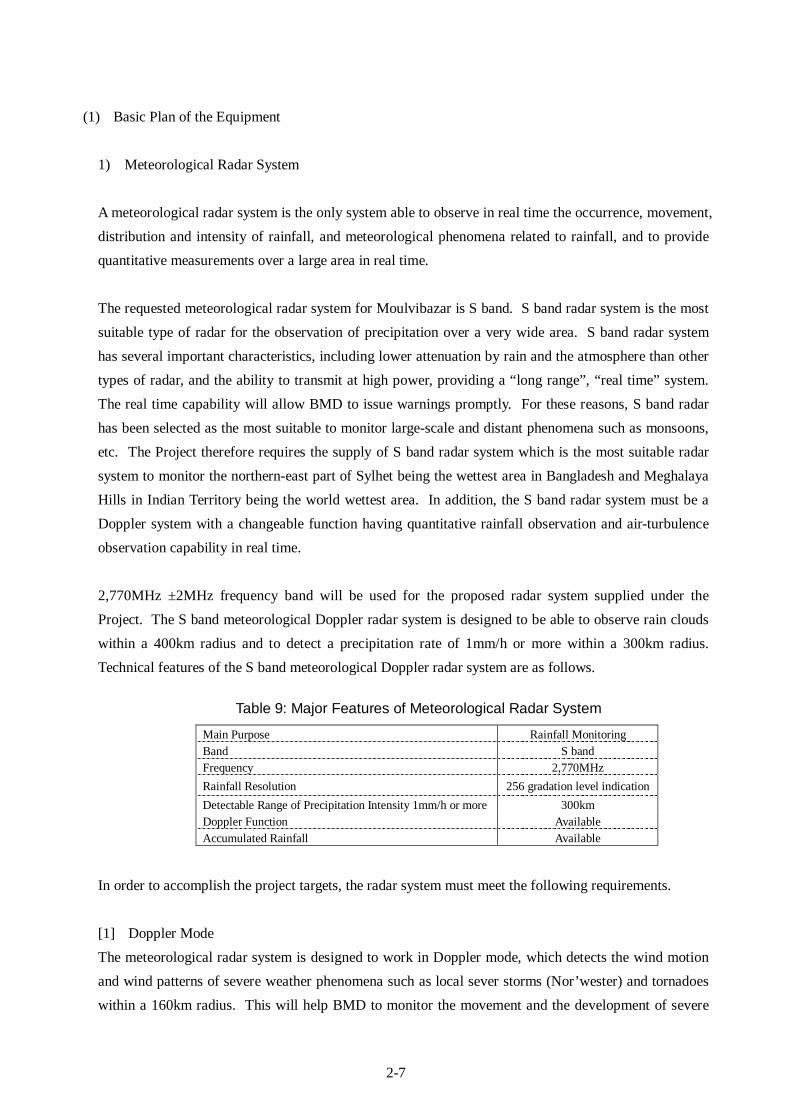
1) Meteorological Radar System A meteorological radar system is the only system able to observe in real time the occurrence, movement, distribution and intensity of rainfall, and meteorological phenomena related to rainfall, and to provide quantitative measurements over a large area in real time. The requested meteorological radar system for Moulvibazar is S band. S band radar system is the most suitable type of radar for the observation of precipitation over a very wide area. S band radar system has several important characteristics, including lower attenuation by rain and the atmosphere than other types of radar, and the ability to transmit at high power, providing a “long range”, “real time” system. The real time capability will allow BMD to issue warnings promptly. For these reasons, S band radar has been selected as the most suitable to monitor large-scale and distant phenomena such as monsoons, etc. The Project therefore requires the supply of S band radar system which is the most suitable radar system to monitor the northern-east part of Sylhet being the wettest area in Bangladesh and Meghalaya Hills in Indian Territory being the world wettest area. In addition, the S band radar system must be a Doppler system with a changeable function having quantitative rainfall observation and air-turbulence observation capability in real time. 2,770MHz ±2MHz frequency band will be used for the proposed radar system supplied under the Project. The S band meteorological Doppler radar system is designed to be able to observe rain clouds within a 400km radius and to detect a precipitation rate of 1mm/h or more within a 300km radius. Technical features of the S band meteorological Doppler radar system are as follows.
Table 9: Major Features of Meteorological Radar System
Main Purpose Rainfall Monitoring Band S band Frequency 2,770MHz Rainfall Resolution 256 gradation level indication Detectable Range of Precipitation Intensity 1mm/h or more 300km Doppler Function Available Accumulated Rainfall Available
In order to accomplish the project targets, the radar system must meet the following requirements. [1] Doppler Mode The meteorological radar system is designed to work in Doppler mode, which detects the wind motion and wind patterns of severe weather phenomena such as local sever storms (Nor’wester) and tornadoes within a 160km radius. This will help BMD to monitor the movement and the development of severe
2-8
weather system for the preparation of more accurate and timely weather forecasting and warning. The doppler mode is essential to allow for more accurate forecasting and longer forecast prediction times. [2] CAPPI (Constant Altitude PPI (Plan Position Indicator)) Mode CAPPI is a horizontal cross-section display at an altitude which can be specified by the user. It is derived from the interpolation of volumetric data. Data from all azimuth and elevation points are used in the calculation of precipitation intensity in order to generate the display for a specified altitude. The product displays constant altitude information from 3-dimensional raw data obtained by scans at multiple elevations. To get 3 dimensional data, the radar antenna can operate in "volumetric scan" mode, changing the antenna elevation at regular time intervals. For the estimation of rainfall from a convective system and the preparation of composite pictures using multiple radar systems, accurate observed data, especially CAPPI data at an altitude of 2km or 3km, is required. An automatic multi-level CAPPI function will be provided with the proposed radar systems.
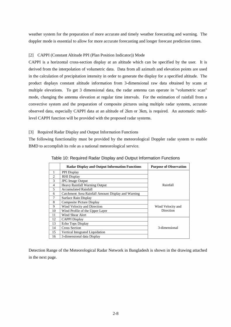
[3] Required Radar Display and Output Information Functions The following functionality must be provided by the meteorological Doppler radar system to enable BMD to accomplish its role as a national meteorological service.
Table 10: Required Radar Display and Output Information Functions
Radar Display and Output Information Functions Purpose of Observation 1 PPI Display 2 RHI Display 3 JPG Image Output 4 Heavy Rainfall Warning Output 5 Accumulated Rainfall 6 Catchment Area Rainfall Amount Display and Warning 7 Surface Rain Display
Rainfall
8 Composite Picture Display 9 Wind Velocity and Direction 10 Wind Profile of the Upper Layer 11 Wind Shear Alert
Wind Velocity and Direction
12 CAPPI Display 13 Echo Tops Display 14 Cross Section 15 Vertical Integrated Liquidation 16 3-dimensional data Display
3-dimensional
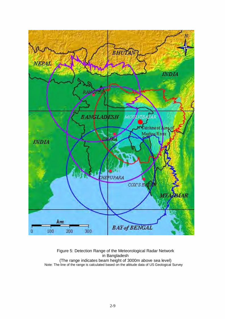
Detection Range of the Meteorological Radar Network in Bangladesh is shown in the drawing attached in the next page.
2-9
Figure 5: Detection Range of the Meteorological Radar Network in Bangladesh
(The range indicates beam height of 3000m above sea level) Note: The line of the range is calculated based on the altitude data of US Geological Survey
2-10
2) Meteorological Radar Data Display System BMD’s forecasters are required to do a substantial amount of work, at a number of locations, very rapidly, in order to produce the required outputs, therefore meteorological radar data display systems are to be installed at the following places. In addition, the system must have the ability to receive and display all the meteorological products in real time for routine weather forecasting & warning. Displays of the system must be minimized heat production for effective room cooling , power-saving type and less screen reflections for smooth and long time operation.
a) Observation Rooms of Moulvibazar Meteorological Radar Tower Building b) SWC c) FFWC
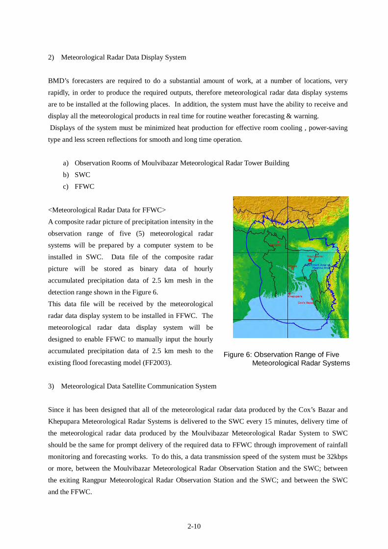
<Meteorological Radar Data for FFWC> A composite radar picture of precipitation intensity in the observation range of five (5) meteorological radar systems will be prepared by a computer system to be installed in SWC. Data file of the composite radar picture will be stored as binary data of hourly accumulated precipitation data of 2.5 km mesh in the detection range shown in the Figure 6. This data file will be received by the meteorological radar data display system to be installed in FFWC. The meteorological radar data display system will be designed to enable FFWC to manually input the hourly accumulated precipitation data of 2.5 km mesh to the existing flood forecasting model (FF2003).
3) Meteorological Data Satellite Communication System Since it has been designed that all of the meteorological radar data produced by the Cox’s Bazar and Khepupara Meteorological Radar Systems is delivered to the SWC every 15 minutes, delivery time of the meteorological radar data produced by the Moulvibazar Meteorological Radar System to SWC should be the same for prompt delivery of the required data to FFWC through improvement of rainfall monitoring and forecasting works. To do this, a data transmission speed of the system must be 32kbps or more, between the Moulvibazar Meteorological Radar Observation Station and the SWC; between the exiting Rangpur Meteorological Radar Observation Station and the SWC; and between the SWC and the FFWC.
Figure 6: Observation Range of Five Meteorological Radar Systems
2-11
In order to transmit the meteorological radar data to SWC or FFWC every 15 minutes, currently there are two options, one is the existing BTTB land-line and another one is a satellite communication link. However, it has been finally decided to use the satellite communication link for the Project due to the following reasons.
• Since the satellite communication links have already been used between the Cox’s Bazar Meteorological Radar System and SWC; and between the Khepupara Meteorological Radar System and SWC, charge for a communication satellite transponder (space segment) for the Project will be cheaper than the charge for a dedicated line of the existing land-line.
• There are no countermeasures against lightening surge in the existing land-line (high potentiality for the radar system to receive a serious damage).
• Due to the long distance of the existing land-line, it takes long time to identify a specific cause for a technical issue and restore a failed system.
• Since the maintenance of the dedicated line depends on BTTB to a great extent, BMD and FFWC is unable to independently take quick movement in case of emergency.
. The transmission times for the radar data streams to the SWC and FFWC are as follows.
Table 11: Required Transmission Time at Transmission Speed 32kbps (Moulvibazar - SWC)
Moulvibazar Meteorological Radar Data Transmission Time Numerical Rainfall and Doppler PPI Data for a Fixed Elevation Angle (240kBytes) 1.3min Numerical Rainfall and Doppler PPI Data for 10 Elevation Angles (2.4Mbytes) 12.5min
Table 12: Required Transmission Time at Transmission Speed 32kbps (SWC - FFWC)
Meteorological Radar Data Transmission Time Precipitation Data of National Composite Picture (360Mbytes) 2.2min
Transmission of all of the radar data from the Meteorological Radar Stations to the SWC and from SWC to FFWC is required, especially during a disaster, therefore, as previously mentioned, the most suitable band for high-speed satellite communication links is C-band, because of the low rain attenuation.
Table 13: Required Conditions of Meteorological Data Satellite Communication System
Bandwidth C band Data Transmission Speed 32kbps or more
Moulvibazar Radar System - SWC: 100kHz or more FFWC - SWC: 100kHz or more Existing Rangpur Radar System - SWC: 100kHz or more Cox’s Bazar Radar System - SWC: 100kHz or more Khepupara Radar System - SWC: 100kHz or more
Required Bandwidth of Transponder
Total:500kHz or more

2-12
For transmitting all the meteorological radar data from the Moulvibazar and existing Rangpur Meteorological Radar Observation Stations to SWC and from SWC to FFWC, the transponder to be selected for the Project must satisfy the following requirements as the same as from the Cox’s Bazar and Khepupara Meteorological Radar Observation Stations to SWC.
1) Satellite Beam : C band regional beam for Southeast Asia area including Bangladesh
2) Frequency : Up Link 5925 - 6425 [MHz] 3) Down Link : 3700 - 4200 [MHz] 4) Polarizations : Orthogonal Linear 5) Satellite Maximum EIRP : more than 39.5 [dBW] 6) Satellite G/T : more than -2.2 [dB/K] 7) Satellite SFD : less than -86.5 [dBW/m2] 8) Satellite Orbital Slot (longitude) : 60°E - 140°E
EIRP Effective Isotropic Radiated Power - This term describes the strength of the signal leaving the satellite antenna or the transmitting earth station antenna, and is used in determining the C/N and S/N. The transmit power value in units of dBW is expressed by the product of the transponder output power and the gain of the satellite transmit antenna. G/T Figure of merit of an antenna and low noise amplifier combination expressed in dB. "G" is the net gain of the system and "T" is the noise temperature of the system. SFD - Saturation Flux Density The power required to achieve saturation of a single repeater channel on the satellite.
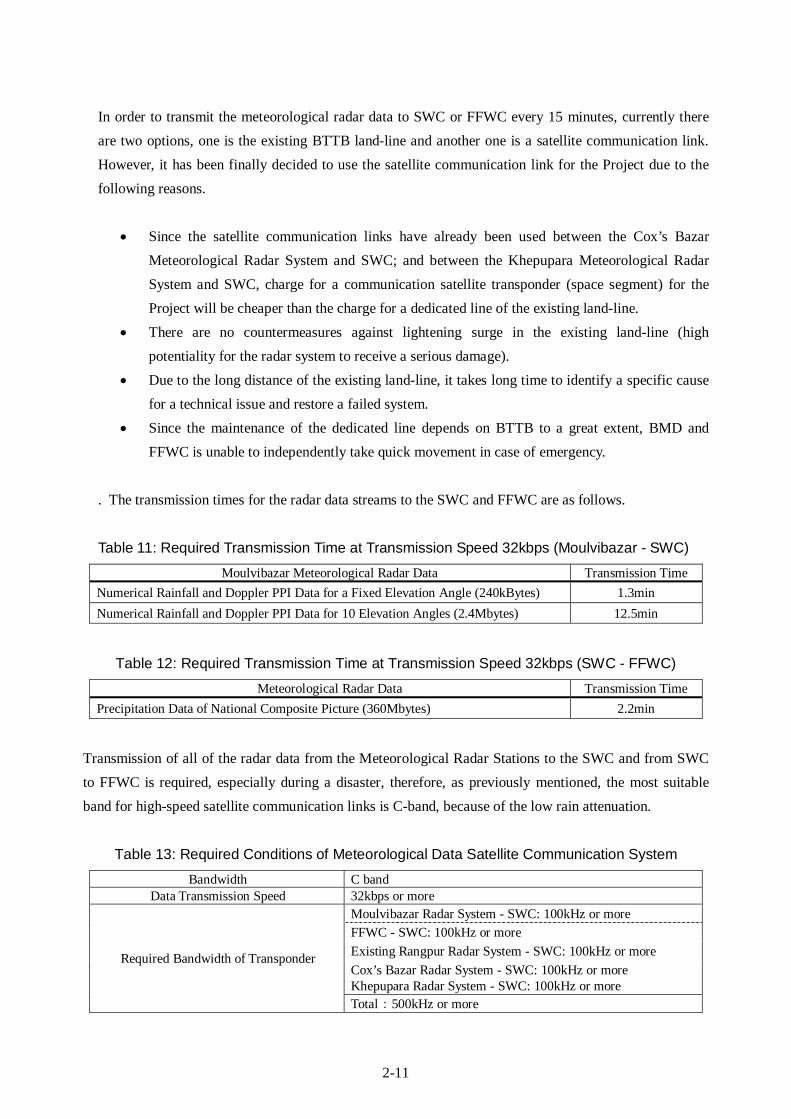
4) Existing Radar System 8bit Improvement The meteorological radar data (3 bit, 6 gradation level indication) produced by the existing Dhaka and Rangpur Meteorological Radar Systems will be upgraded to 8 bit, 256 gradation level indication. The upgraded meteorological radar data will be combined with the meteorological radar data (precipitation intensity 8 bit data) produced by the Moulvibazar, Cox’s Bazar and Khepupara Meteorological Radar Systems to process and make a national composite picture at the SWC. Due to implementation of this 8 bit improvement, resolution of the meteorological radar data (precipitation data) produced by all the Meteorological Radar Systems will be unified.
2-13
Table 14: Comparison Table of Before / After Improvement of existing Dhaka and Rangpur Meteorological Radar Stations
Present After Improvement
Meteorological Radar Station ・Dhaka ・Rangpur
Observed Data Precipitation Intensity Data (3 bit) Specified vertical angle numeric precipitation data (8 bit)
Data Volume
・orthogonal coordinate format ・240x240 mesh ・3 bit data Total: 30kbyte
・polar coordinate format ・320 rangex360 degree ・8 bit data Total: 240kbyte
Precipitation Intensity Resolution 6 gradation level indication 256 gradation level indication
Display
・Precipitation Intensity ・PPI Display ・Heavy Rainfall Warning Output ・Accumulated Rainfall ・Rainfall Distribution ・Catchment Area Rainfall Amount Display and Warning
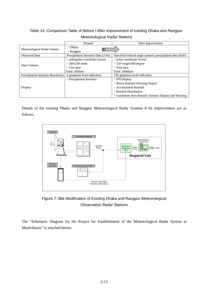
Details of the existing Dhaka and Rangpur Meteorological Radar Systems 8 bit Improvement are as follows.
Figure 7: 8bit Modification of Existing Dhaka and Rangpur Meteorological Observation Radar Stations
The “Schematic Diagram for the Project for Establishment of the Meteorological Radar System at Moulvibazar” is attached hereto.
Log VideoSignal
Radar DataAcquisition
Unit
AntennaController
Antenna
Transmitter/Receiver
CommunicationControl Unit
VSAT
Operation Console/DVIP
Antenna Angle Signal(Azimuth and Elevation)
HUB HUB
Required Unit
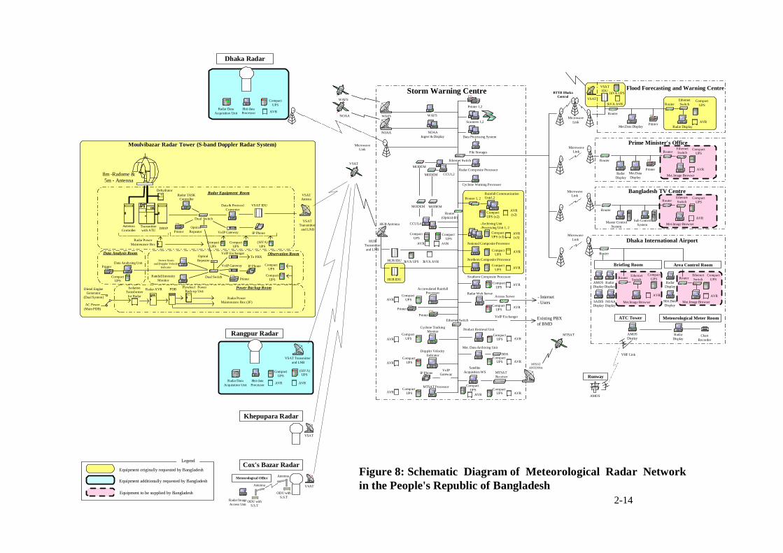
Figure 8: Schematic Diagram of Meteorological Radar Networkin the People's Republic of Bangladesh
Khepupara Radar
Cox's Bazar Radar
Ethernet Switch
Storm Warning Centre
Radar Display
MicrowaveLink
WAFS
NOAA
WAFS
NOAA
Flood Forecasting and Warning Centre
Printer
Prime Minister's Office
Bangladesh TV Centre
Dhaka International Airport
Briefing Room Area Control Room
RadarDisplay
Met.DataDisplay
Printer
RadarDisplay
AMOSDisplay
MicrowaveLink
VSAT
PrinterNOAADisplay
Radar Composite Processor
File Storages
WAFS
Printer 1,2
MicrowaveLink
MicrowaveLink
MicrowaveLink
MODEM
MODEM CCU1,2
MTSAT
BTTB DhakaCentral
Data Processing System
Cyclone Warning Processor
HUBTransmitterand LNB
MODEM
Doppler Velocity Indicator
Radar Web Server
CCU3,4
Access Server
Product Retrieval Unit
MODEM
Met. Data Archiving Unit
Cyclone Tracking Monitor
DDS
Ethernet Switch
HUB Antenna
Printer
Accumulated RainfallProcessor
VoIPGatewayIP Phone
Compact UPS
Compact UPS
Compact UPS
Compact UPS
Compact UPS
Compact UPS
Printer
AVR
AVR
AVRAVR
AVR
AVR AVR
SatelliteAcquisition WS MTSAT
Receiver
AVRCompact
UPS AVR
- Internet- Users
Compact UPSAVR
VoIP Exchanger Existing PBXof BMD
MTSATANTENNA
MTSAT Processor
AVR
AVR
AVR
AVR(x2)
Compact UPSAVR
-Archiving Unit-Processing Unit 1, 2
AVR(x3)
Rainfall CommunicationUnit1,2
National Composite Processor
Northern Composite Processor
CompactUPS (x2)
CompactUPS (x3)
CompactUPS
CompactUPS
Southern Composite Processor
CompactUPS
HUB IDU 3kVA UPS 3kVA AVR
HUB IDU
Router(Optical-IF)
Router 1, 2
Compact UPS
Router
Router
EthernetSwitch
Router
RadarDisplay
SADISDisplay
Equipment originally requested by Bangladesh
Legend
Router
Met.Image Browser
EthernetSwitchRouter
AVR
CompactUPS
AVR
CompactUPS
Met.Image Browser
EthernetSwitchRouter
AVR
CompactUPS
ATC Tower Meteorological Meter Room
VHF Link
AMOSDisplay
RadarDisplay
ChartRecorder
Runway
AMOS
Met.Image Browser
Router
AVR
CompactUPS
Met.Image Browser
EthernetSwitchRouter
AVR
CompactUPS
Met.DataDisplay
Meteorological Office
Radar ImageAccess Unit
Antenna
Antenna
ODU withS.S.T
ODU withS.S.T
VSAT
VSAT
VSATIDU
1kVA AVR
Router
Sub ControlSystem
NOAAIngest & Display
Scanners 1,2
Compact UPS
Met.Data Display
Master ControlSystem
1kVA UPS
VSAT
Equipment additionally requested by Bangladesh
Equipment to be supplied by Bangladesh
EthernetSwitch
Moulvibazar Radar Tower (S-band Doppler Radar System)
VSATAntena
Dehydrator
AntennaController
Transmitterwith ATU DRSP
Radar TASKController
(1kVA)UPS
IsolationTransformer
for Radar
Radar AVR
Radar Equipment Room
Dual Switch
Radar PowerMaintenance Box
Flywheel PowerBack-up Unit
Power Backup Room
Data & ProtocolConverter
8m -Radome &5m - Antenna
IP Phone VoIP Gateway
Rainfall IntensityMonitor
Dual Switch
Observation Room
IP Phone
CompactUPS
Printer
Printer
VoIP Gateway
Radar PowerMaintenance Box (3F)
CompactUPS
CompactUPS
VSAT IDU
PDB
Data Analysing UnitPrinter
CompactUPS
CompactUPS
Data Analysis Room
AC Power(Main PDB)
Diesel EngineGenerator
(Dual System)
Optical Repeater
OpticalRepeater
Severe Stormand Doppler Velocity
Indicator
VSATTransmitter and LNB
VoIP ExchangerTo PBX
Rangpur Radar
VSAT Transmitter and LNB
Radar DataAcquisition Unit
8bit dataProcessor AVR
CompactUPS
AVR
(1kVA)UPS
Dhaka Radar
Radar DataAcquisition Unit
8bit dataProcessor AVR
CompactUPS
2-14
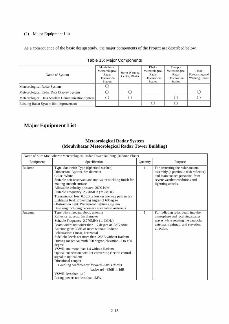
2-15
(2) Major Equipment List
As a consequence of the basic design study, the major components of the Project are described below.
Table 15: Major Components
Name of System
Moulvibazar Meteorological
Radar Observation
Station
Storm Warning Centre, Dhaka
Dhaka Meteorological
Radar Observation
Station
Rangpur Meteorological
Radar Observation
Station
Flood Forecasting and Warning Centre
Meteorological Radar System ○ Meteorological Radar Data Display System ○ ○ ○ Meteorological Data Satellite Communication System ○ ○ ○ ○ Existing Radar System 8bit Improvement ○ ○
Major Equipment List
Meteorological Radar System (Moulvibazar Meteorological Radar Tower Building)
Name of Site: Moulvibazar Meteorological Radar Tower Building (Radome Floor)
Equipment Specification Quantity Purpose
Radome Type: Sandwich Type (Spherical surface) Dimension: Approx. 8m diameter Color: White Suitable non-observant and non-water stickling finish for making smooth surface Allowable velocity pressure: 2600 N/m2 Suitable Frequency: 2,770MHz (±2MHz) Transmission loss: 0.5dB or less on one way path in dry Lightning Rod: Protecting angles of 60degree Obstruction light: Waterproof lightning system Base ring including necessary installation materials
1 For protecting the radar antenna assembly (a parabolic dish reflector) and maintenance personnel from severe weather conditions and lightning attacks.
Antenna Type: Horn feed parabolic antenna Reflector: approx. 5m diameter Suitable Frequency: 2,770MHz (±2MHz) Beam width: not wider than 1.7 degree at -3dB point Antenna gain: 39dB or more without Radome Polarization: Linear, horizontal Side lobe level: not more than -25dB without Radome Driving range: Azimuth 360 degree, elevation -2 to +90 degree VSWR: not more than 1.4 without Radome Optical connection box: For converting electric control signal to optical one Directional coupler:
Coupling coefficiency: forward –50dB ±2dB backward –35dB ±1dB
VSWR: less than 1.10 Rating power: not less than 1MW
1 For radiating radar beam into the atmosphere and receiving scatter waves while rotating the parabola antenna in azimuth and elevation direction.
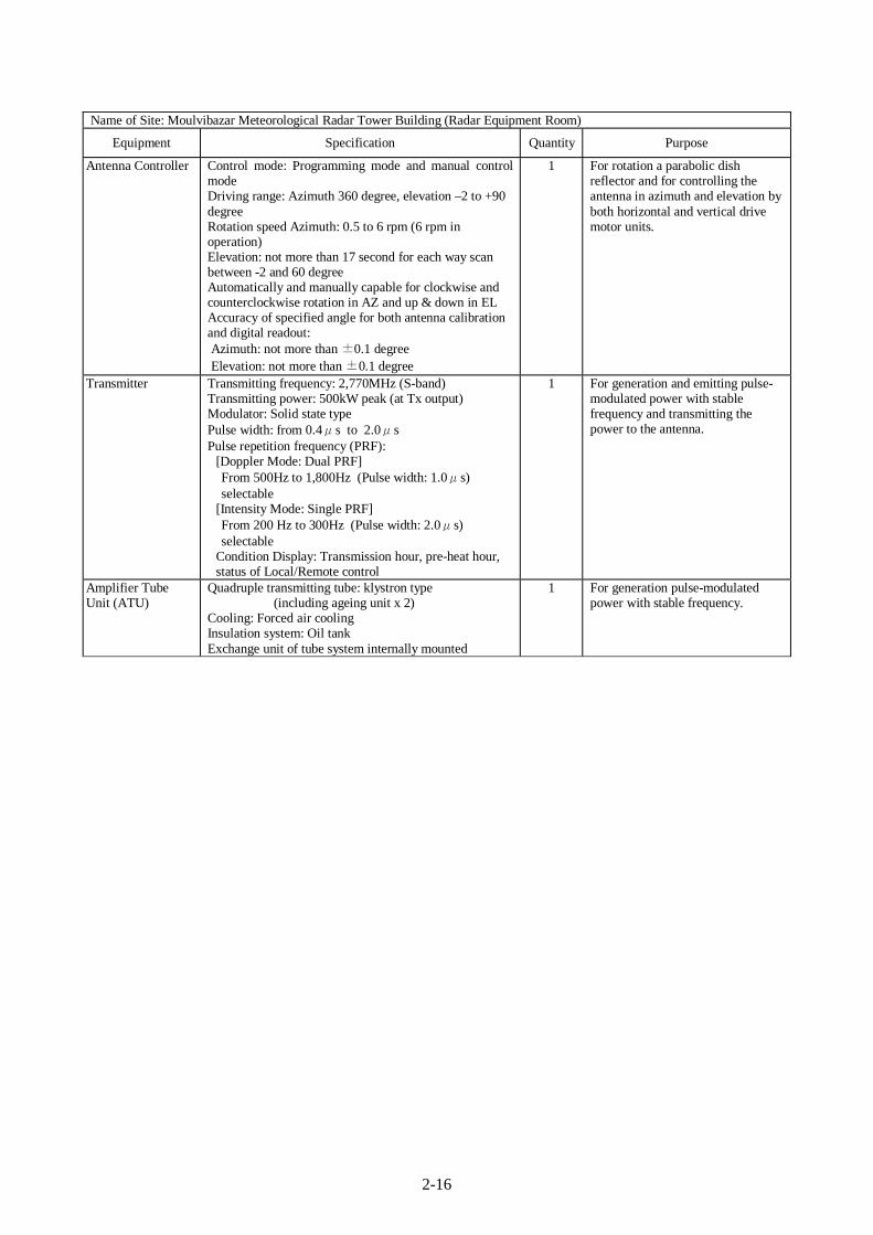
2-16
Name of Site: Moulvibazar Meteorological Radar Tower Building (Radar Equipment Room)
Equipment Specification Quantity Purpose
Antenna Controller Control mode: Programming mode and manual control mode Driving range: Azimuth 360 degree, elevation –2 to +90 degree Rotation speed Azimuth: 0.5 to 6 rpm (6 rpm in operation) Elevation: not more than 17 second for each way scan between -2 and 60 degree Automatically and manually capable for clockwise and counterclockwise rotation in AZ and up & down in EL Accuracy of specified angle for both antenna calibration and digital readout: Azimuth: not more than ±0.1 degree Elevation: not more than ±0.1 degree
1 For rotation a parabolic dish reflector and for controlling the antenna in azimuth and elevation by both horizontal and vertical drive motor units.
Transmitter Transmitting frequency: 2,770MHz (S-band) Transmitting power: 500kW peak (at Tx output) Modulator: Solid state type Pulse width: from 0.4μs to 2.0μs Pulse repetition frequency (PRF):
[Doppler Mode: Dual PRF] From 500Hz to 1,800Hz (Pulse width: 1.0μs) selectable
[Intensity Mode: Single PRF] From 200 Hz to 300Hz (Pulse width: 2.0μs) selectable
Condition Display: Transmission hour, pre-heat hour, status of Local/Remote control
1 For generation and emitting pulse- modulated power with stable frequency and transmitting the power to the antenna.
Amplifier Tube Unit (ATU)
Quadruple transmitting tube: klystron type (including ageing unit x 2) Cooling: Forced air cooling Insulation system: Oil tank Exchange unit of tube system internally mounted
1 For generation pulse-modulated power with stable frequency.
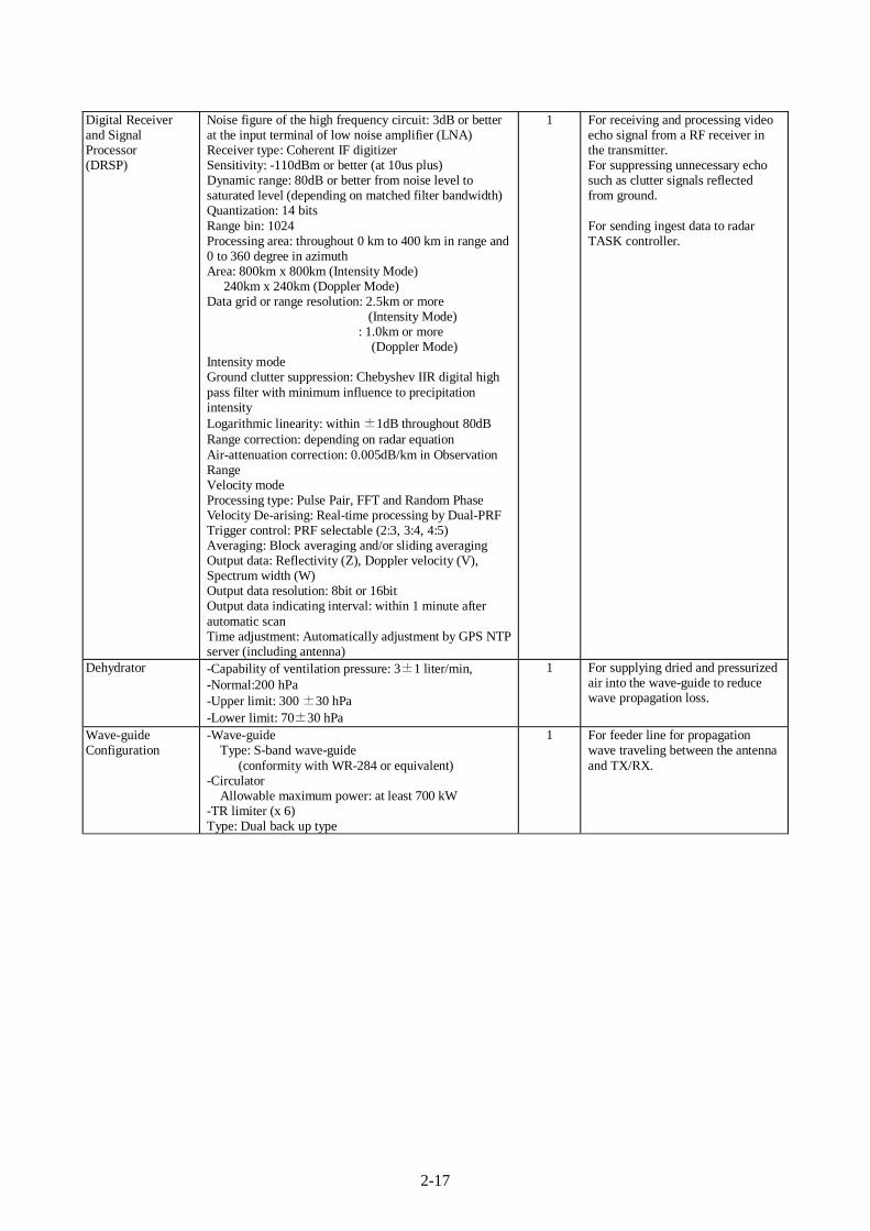
2-17
Digital Receiver and Signal Processor (DRSP)
Noise figure of the high frequency circuit: 3dB or better at the input terminal of low noise amplifier (LNA) Receiver type: Coherent IF digitizer Sensitivity: -110dBm or better (at 10us plus) Dynamic range: 80dB or better from noise level to saturated level (depending on matched filter bandwidth) Quantization: 14 bits Range bin: 1024 Processing area: throughout 0 km to 400 km in range and 0 to 360 degree in azimuth Area: 800km x 800km (Intensity Mode) 240km x 240km (Doppler Mode) Data grid or range resolution: 2.5km or more
(Intensity Mode) : 1.0km or more
(Doppler Mode) Intensity mode Ground clutter suppression: Chebyshev IIR digital high pass filter with minimum influence to precipitation intensity Logarithmic linearity: within ±1dB throughout 80dB Range correction: depending on radar equation Air-attenuation correction: 0.005dB/km in Observation Range Velocity mode Processing type: Pulse Pair, FFT and Random Phase Velocity De-arising: Real-time processing by Dual-PRF Trigger control: PRF selectable (2:3, 3:4, 4:5) Averaging: Block averaging and/or sliding averaging Output data: Reflectivity (Z), Doppler velocity (V), Spectrum width (W) Output data resolution: 8bit or 16bit Output data indicating interval: within 1 minute after automatic scan Time adjustment: Automatically adjustment by GPS NTP server (including antenna)
1 For receiving and processing video echo signal from a RF receiver in the transmitter. For suppressing unnecessary echo such as clutter signals reflected from ground. For sending ingest data to radar TASK controller.
Dehydrator -Capability of ventilation pressure: 3±1 liter/min, -Normal:200 hPa -Upper limit: 300 ±30 hPa -Lower limit: 70±30 hPa
1 For supplying dried and pressurized air into the wave-guide to reduce wave propagation loss.
Wave-guide Configuration
-Wave-guide Type: S-band wave-guide
(conformity with WR-284 or equivalent) -Circulator
Allowable maximum power: at least 700 kW -TR limiter (x 6) Type: Dual back up type
1 For feeder line for propagation wave traveling between the antenna and TX/RX.
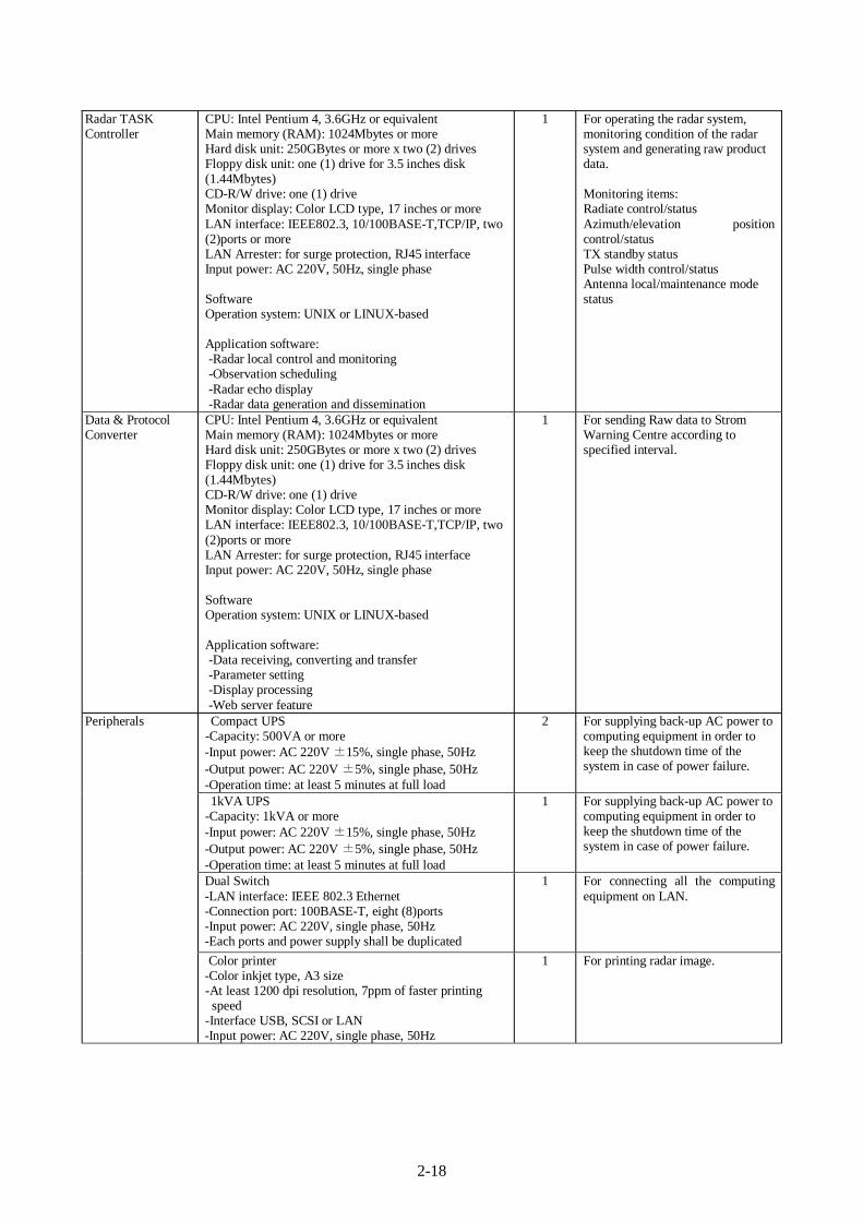
2-18
Radar TASK Controller
CPU: Intel Pentium 4, 3.6GHz or equivalent Main memory (RAM): 1024Mbytes or more Hard disk unit: 250GBytes or more x two (2) drives Floppy disk unit: one (1) drive for 3.5 inches disk (1.44Mbytes) CD-R/W drive: one (1) drive Monitor display: Color LCD type, 17 inches or more LAN interface: IEEE802.3, 10/100BASE-T,TCP/IP, two (2)ports or more LAN Arrester: for surge protection, RJ45 interface Input power: AC 220V, 50Hz, single phase Software Operation system: UNIX or LINUX-based Application software: -Radar local control and monitoring -Observation scheduling -Radar echo display -Radar data generation and dissemination
1 For operating the radar system, monitoring condition of the radar system and generating raw product data. Monitoring items: Radiate control/status Azimuth/elevation position control/status TX standby status Pulse width control/status Antenna local/maintenance mode status
Data & Protocol Converter
CPU: Intel Pentium 4, 3.6GHz or equivalent Main memory (RAM): 1024Mbytes or more Hard disk unit: 250GBytes or more x two (2) drives Floppy disk unit: one (1) drive for 3.5 inches disk (1.44Mbytes) CD-R/W drive: one (1) drive Monitor display: Color LCD type, 17 inches or more LAN interface: IEEE802.3, 10/100BASE-T,TCP/IP, two (2)ports or more LAN Arrester: for surge protection, RJ45 interface Input power: AC 220V, 50Hz, single phase Software Operation system: UNIX or LINUX-based Application software: -Data receiving, converting and transfer -Parameter setting -Display processing -Web server feature
1 For sending Raw data to Strom Warning Centre according to specified interval.
Compact UPS -Capacity: 500VA or more
-Input power: AC 220V ±15%, single phase, 50Hz -Output power: AC 220V ±5%, single phase, 50Hz -Operation time: at least 5 minutes at full load
2 For supplying back-up AC power to computing equipment in order to keep the shutdown time of the system in case of power failure.
1kVA UPS -Capacity: 1kVA or more
-Input power: AC 220V ±15%, single phase, 50Hz -Output power: AC 220V ±5%, single phase, 50Hz -Operation time: at least 5 minutes at full load
1 For supplying back-up AC power to computing equipment in order to keep the shutdown time of the system in case of power failure.
Dual Switch -LAN interface: IEEE 802.3 Ethernet -Connection port: 100BASE-T, eight (8)ports -Input power: AC 220V, single phase, 50Hz -Each ports and power supply shall be duplicated
1 For connecting all the computing equipment on LAN.
Peripherals
Color printer -Color inkjet type, A3 size -At least 1200 dpi resolution, 7ppm of faster printing speed
-Interface USB, SCSI or LAN -Input power: AC 220V, single phase, 50Hz
1 For printing radar image.
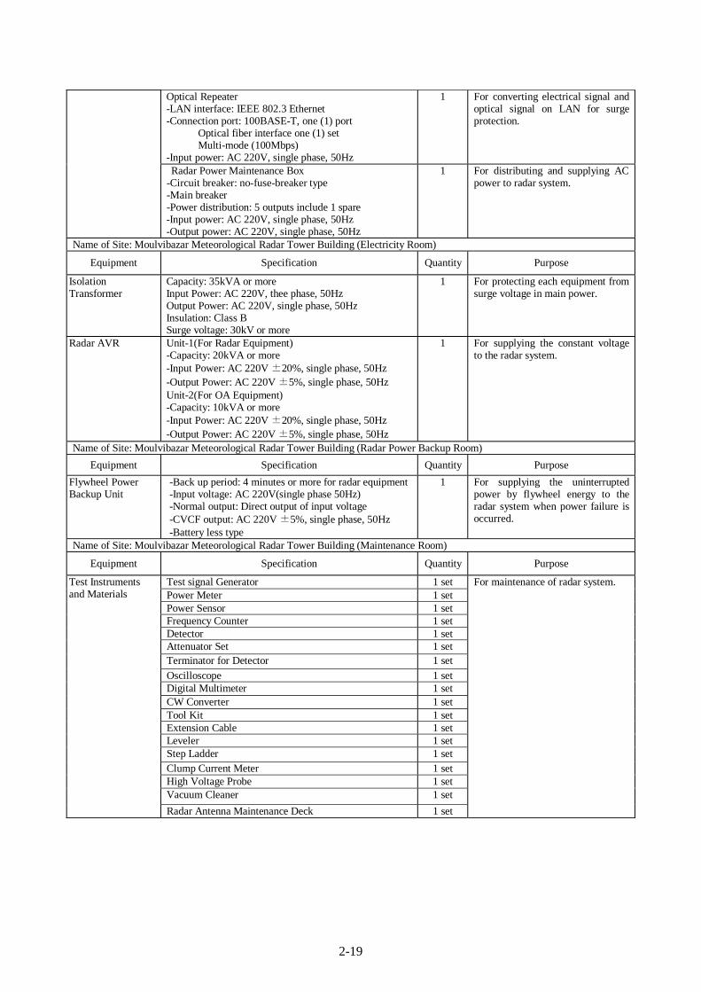
2-19
Optical Repeater -LAN interface: IEEE 802.3 Ethernet -Connection port: 100BASE-T, one (1) port Optical fiber interface one (1) set Multi-mode (100Mbps) -Input power: AC 220V, single phase, 50Hz
1 For converting electrical signal and optical signal on LAN for surge protection.
Radar Power Maintenance Box -Circuit breaker: no-fuse-breaker type -Main breaker -Power distribution: 5 outputs include 1 spare
-Input power: AC 220V, single phase, 50Hz -Output power: AC 220V, single phase, 50Hz
1 For distributing and supplying AC power to radar system.
Name of Site: Moulvibazar Meteorological Radar Tower Building (Electricity Room)
Equipment Specification Quantity Purpose
Isolation Transformer
Capacity: 35kVA or more Input Power: AC 220V, thee phase, 50Hz Output Power: AC 220V, single phase, 50Hz Insulation: Class B Surge voltage: 30kV or more
1 For protecting each equipment from surge voltage in main power.
Radar AVR
Unit-1(For Radar Equipment) -Capacity: 20kVA or more -Input Power: AC 220V ±20%, single phase, 50Hz -Output Power: AC 220V ±5%, single phase, 50Hz Unit-2(For OA Equipment) -Capacity: 10kVA or more -Input Power: AC 220V ±20%, single phase, 50Hz -Output Power: AC 220V ±5%, single phase, 50Hz
1 For supplying the constant voltage to the radar system.
Name of Site: Moulvibazar Meteorological Radar Tower Building (Radar Power Backup Room) Equipment Specification Quantity Purpose
Flywheel Power Backup Unit
-Back up period: 4 minutes or more for radar equipment -Input voltage: AC 220V(single phase 50Hz) -Normal output: Direct output of input voltage -CVCF output: AC 220V ±5%, single phase, 50Hz -Battery less type
1 For supplying the uninterrupted power by flywheel energy to the radar system when power failure is occurred.
Name of Site: Moulvibazar Meteorological Radar Tower Building (Maintenance Room)
Equipment Specification Quantity Purpose
Test signal Generator 1 set Power Meter 1 set Power Sensor 1 set Frequency Counter 1 set Detector 1 set Attenuator Set 1 set Terminator for Detector 1 set Oscilloscope 1 set Digital Multimeter 1 set CW Converter 1 set Tool Kit 1 set Extension Cable 1 set Leveler 1 set Step Ladder 1 set Clump Current Meter 1 set High Voltage Probe 1 set Vacuum Cleaner 1 set
Test Instruments and Materials
Radar Antenna Maintenance Deck 1 set
For maintenance of radar system.
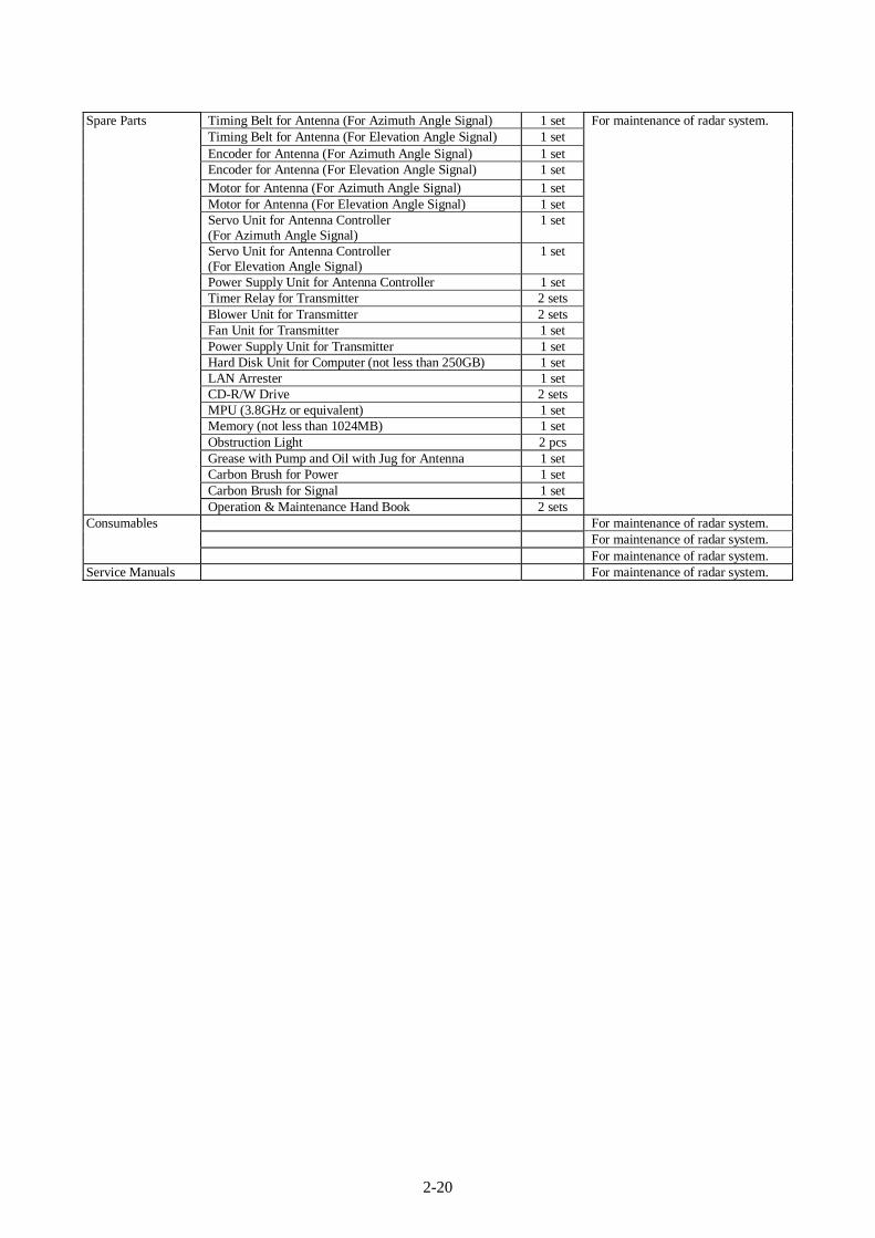
2-20
Timing Belt for Antenna (For Azimuth Angle Signal) 1 set Timing Belt for Antenna (For Elevation Angle Signal) 1 set Encoder for Antenna (For Azimuth Angle Signal) 1 set Encoder for Antenna (For Elevation Angle Signal) 1 set Motor for Antenna (For Azimuth Angle Signal) 1 set Motor for Antenna (For Elevation Angle Signal) 1 set Servo Unit for Antenna Controller (For Azimuth Angle Signal)
1 set
Servo Unit for Antenna Controller (For Elevation Angle Signal)
1 set
Power Supply Unit for Antenna Controller 1 set Timer Relay for Transmitter 2 sets Blower Unit for Transmitter 2 sets Fan Unit for Transmitter 1 set Power Supply Unit for Transmitter 1 set Hard Disk Unit for Computer (not less than 250GB) 1 set LAN Arrester 1 set CD-R/W Drive 2 sets MPU (3.8GHz or equivalent) 1 set Memory (not less than 1024MB) 1 set Obstruction Light 2 pcs Grease with Pump and Oil with Jug for Antenna 1 set Carbon Brush for Power 1 set Carbon Brush for Signal 1 set
Spare Parts
Operation & Maintenance Hand Book 2 sets
For maintenance of radar system.
For maintenance of radar system. For maintenance of radar system.
Consumables
For maintenance of radar system. Service Manuals For maintenance of radar system.
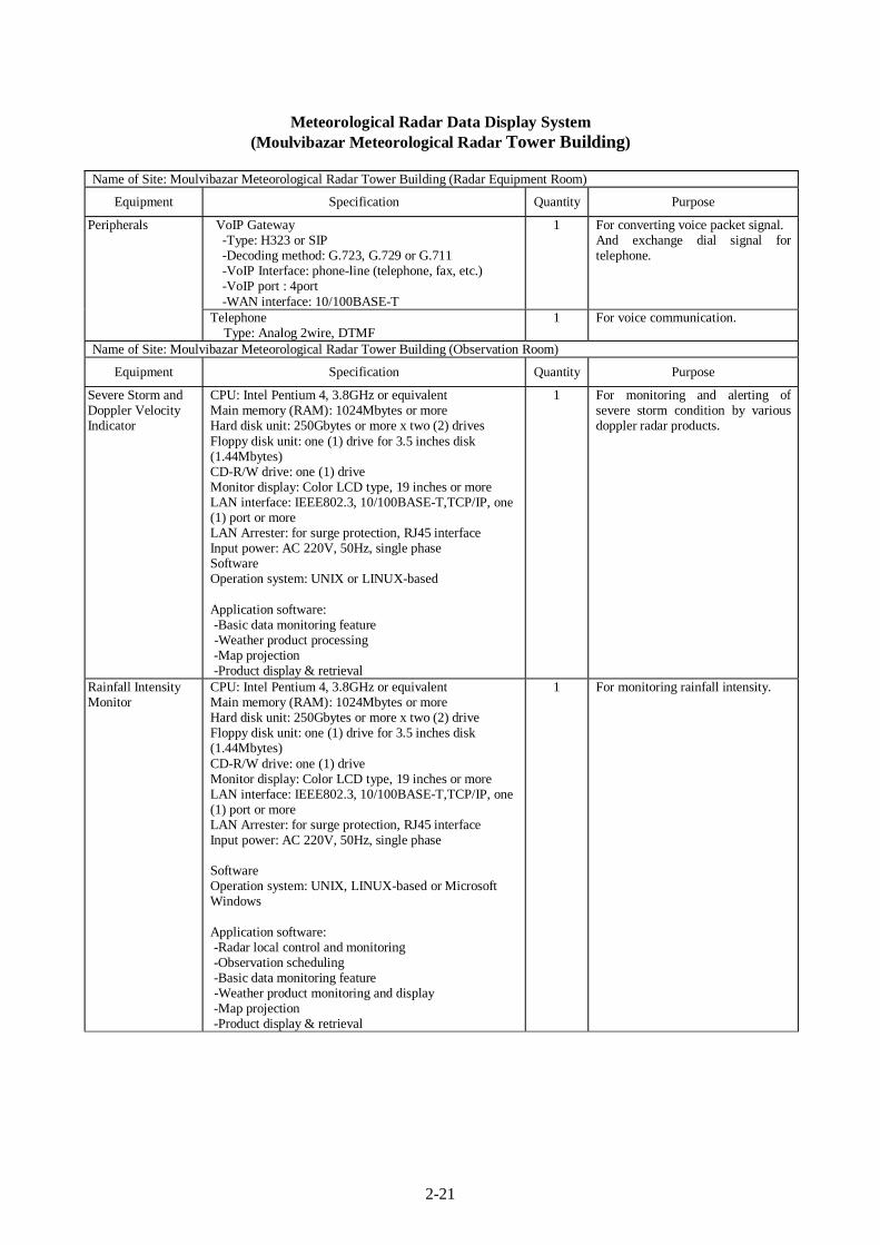
2-21
Meteorological Radar Data Display System (Moulvibazar Meteorological Radar Tower Building)
Name of Site: Moulvibazar Meteorological Radar Tower Building (Radar Equipment Room)
Equipment Specification Quantity Purpose
VoIP Gateway -Type: H323 or SIP -Decoding method: G.723, G.729 or G.711 -VoIP Interface: phone-line (telephone, fax, etc.) -VoIP port : 4port -WAN interface: 10/100BASE-T
1 For converting voice packet signal. And exchange dial signal for telephone.
Peripherals
Telephone Type: Analog 2wire, DTMF
1 For voice communication.
Name of Site: Moulvibazar Meteorological Radar Tower Building (Observation Room)
Equipment Specification Quantity Purpose
Severe Storm and Doppler Velocity Indicator
CPU: Intel Pentium 4, 3.8GHz or equivalent Main memory (RAM): 1024Mbytes or more Hard disk unit: 250Gbytes or more x two (2) drives Floppy disk unit: one (1) drive for 3.5 inches disk (1.44Mbytes) CD-R/W drive: one (1) drive Monitor display: Color LCD type, 19 inches or more LAN interface: IEEE802.3, 10/100BASE-T,TCP/IP, one (1) port or more LAN Arrester: for surge protection, RJ45 interface Input power: AC 220V, 50Hz, single phase Software Operation system: UNIX or LINUX-based Application software: -Basic data monitoring feature -Weather product processing -Map projection -Product display & retrieval
1 For monitoring and alerting of severe storm condition by various doppler radar products.
Rainfall Intensity Monitor
CPU: Intel Pentium 4, 3.8GHz or equivalent Main memory (RAM): 1024Mbytes or more Hard disk unit: 250Gbytes or more x two (2) drive Floppy disk unit: one (1) drive for 3.5 inches disk (1.44Mbytes) CD-R/W drive: one (1) drive Monitor display: Color LCD type, 19 inches or more LAN interface: IEEE802.3, 10/100BASE-T,TCP/IP, one (1) port or more LAN Arrester: for surge protection, RJ45 interface Input power: AC 220V, 50Hz, single phase Software Operation system: UNIX, LINUX-based or Microsoft Windows Application software: -Radar local control and monitoring -Observation scheduling -Basic data monitoring feature -Weather product monitoring and display -Map projection -Product display & retrieval
1 For monitoring rainfall intensity.
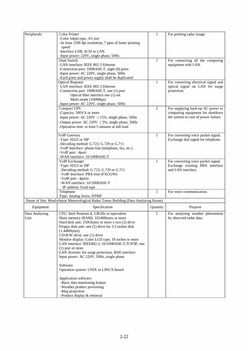
2-22
Color Printer -Color inkjet type, A3 size -At least 1200 dpi resolution, 7 ppm of faster printing
speed -Interface USB, SCSI or LAN -Input power: 220V, single phase, 50Hz
1 For printing radar image.
Dual Switch -LAN interface: IEEE 802.3 Ethernet -Connection port: 100BASE-T, eight (8) ports -Input power: AC 220V, single phase, 50Hz -Each ports and power supply shall be duplicated
1 For connecting all the computing equipment with LAN.
Optical Repeater -LAN interface: IEEE 802.3 Ethernet -Connection port: 100BASE-T, one (1) port Optical fiber interface one (1) set Multi-mode (100Mbps) -Input power: AC 220V, single phase, 50Hz
1 For converting electrical signal and optical signal on LAN for surge protection.
Compact UPS -Capacity: 500VA or more -Input power: AC 220V ±15%, single phase, 50Hz -Output power: AC 220V ±5%, single phase, 50Hz -Operation time: at least 5 minutes at full load
2 For supplying back-up AC power to computing equipment for shutdown the system in case of power failure.
VoIP Gateway -Type: H323 or SIP -Decoding method: G.723, G.729 or G.711 -VoIP Interface: phone-line (telephone, fax, etc.) -VoIP port : 4port -WAN interface: 10/100BASE-T
1 For converting voice packet signal. Exchange dial signal for telephone.
VoIP Exchanger -Type: H323 or SIP -Decoding method: G.723, G.729 or G.711 -VoIP Interface: PBX-line (FXO/2W) -VoIP port : 4ports -WAN interface: 10/100BASE-T
-IP address: fixed type
1 For converting voice packet signal. Exchange existing PBX interface and LAN interface.
Peripherals
Telephone Type: Analog 2wire, DTMF
1 For voice communication.
Name of Site: Moulvibazar Meteorological Radar Tower Building (Data Analyzing Room)
Equipment Specification Quantity Purpose
Data Analyzing Unit
CPU: Intel Pentium 4, 3.8GHz or equivalent Main memory (RAM): 1024Mbytes or more Hard disk unit: 250Gbytes or more x two (2) drive Floppy disk unit: one (1) drive for 3.5 inches disk (1.44Mbytes) CD-R/W drive: one (1) drive Monitor display: Color LCD type, 18 inches or more LAN interface: IEEE802.3, 10/100BASE-T,TCP/IP, one (1) port or more LAN Arrester: for surge protection, RJ45 interface Input power: AC 220V, 50Hz, single phase Software Operation system: UNIX or LINUX-based Application software: -Basic data monitoring feature -Weather product processing -Map projection -Product display & retrieval
1 For analyzing weather phenomena by observed radar data.
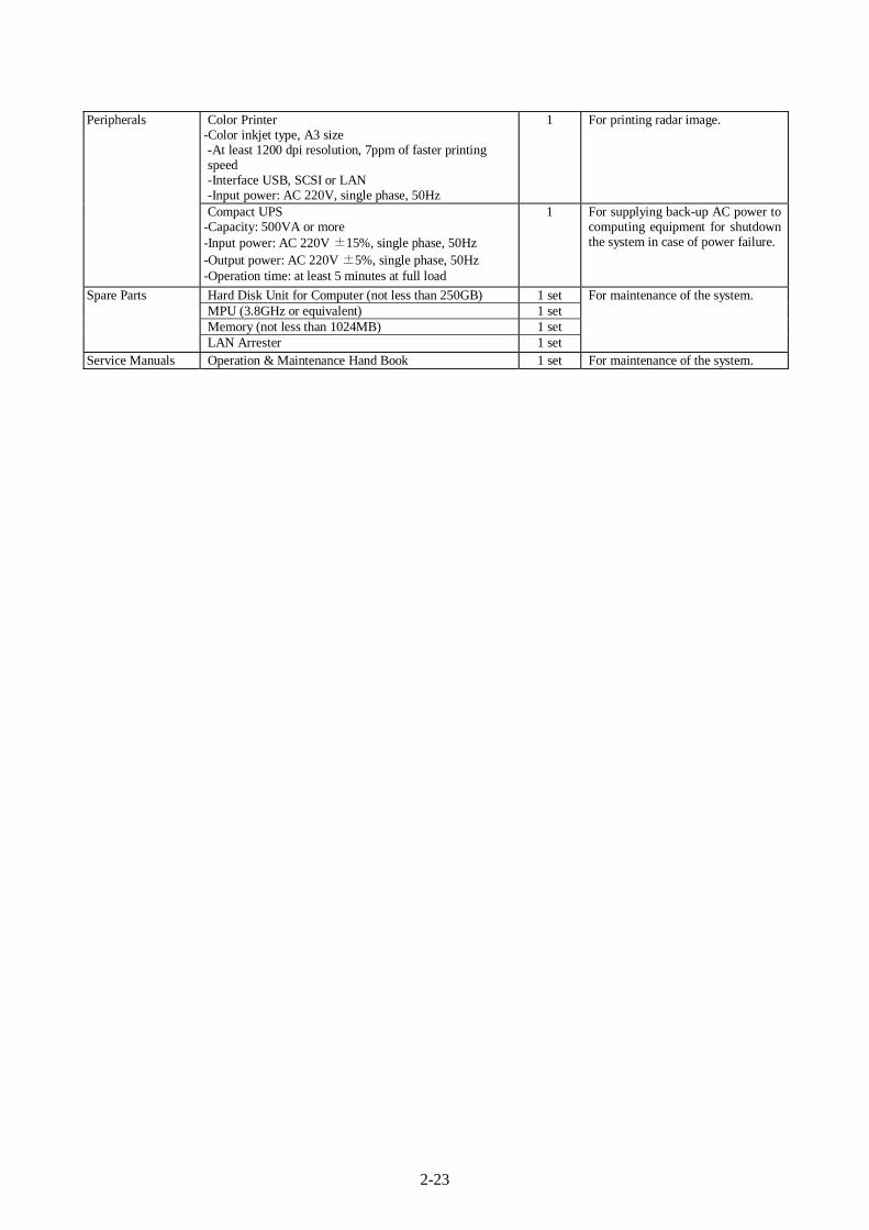
2-23
Color Printer -Color inkjet type, A3 size -At least 1200 dpi resolution, 7ppm of faster printing speed -Interface USB, SCSI or LAN -Input power: AC 220V, single phase, 50Hz
1 For printing radar image. Peripherals
Compact UPS -Capacity: 500VA or more -Input power: AC 220V ±15%, single phase, 50Hz -Output power: AC 220V ±5%, single phase, 50Hz -Operation time: at least 5 minutes at full load
1 For supplying back-up AC power to computing equipment for shutdown the system in case of power failure.
Hard Disk Unit for Computer (not less than 250GB) 1 set MPU (3.8GHz or equivalent) 1 set Memory (not less than 1024MB) 1 set
Spare Parts
LAN Arrester 1 set
For maintenance of the system.
Service Manuals Operation & Maintenance Hand Book 1 set For maintenance of the system.
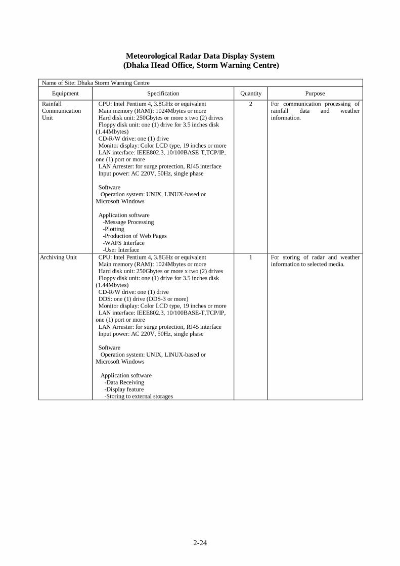
2-24
Meteorological Radar Data Display System (Dhaka Head Office, Storm Warning Centre)
Name of Site: Dhaka Storm Warning Centre
Equipment Specification Quantity Purpose
Rainfall Communication Unit
CPU: Intel Pentium 4, 3.8GHz or equivalent Main memory (RAM): 1024Mbytes or more Hard disk unit: 250Gbytes or more x two (2) drives Floppy disk unit: one (1) drive for 3.5 inches disk
(1.44Mbytes) CD-R/W drive: one (1) drive Monitor display: Color LCD type, 19 inches or more LAN interface: IEEE802.3, 10/100BASE-T,TCP/IP,
one (1) port or more LAN Arrester: for surge protection, RJ45 interface Input power: AC 220V, 50Hz, single phase
Software Operation system: UNIX, LINUX-based or
Microsoft Windows
Application software -Message Processing -Plotting -Production of Web Pages -WAFS Interface -User Interface
2 For communication processing of rainfall data and weather information.
Archiving Unit CPU: Intel Pentium 4, 3.8GHz or equivalent Main memory (RAM): 1024Mbytes or more Hard disk unit: 250Gbytes or more x two (2) drives Floppy disk unit: one (1) drive for 3.5 inches disk
(1.44Mbytes) CD-R/W drive: one (1) drive DDS: one (1) drive (DDS-3 or more) Monitor display: Color LCD type, 19 inches or more LAN interface: IEEE802.3, 10/100BASE-T,TCP/IP,
one (1) port or more LAN Arrester: for surge protection, RJ45 interface Input power: AC 220V, 50Hz, single phase Software Operation system: UNIX, LINUX-based or
Microsoft Windows Application software
-Data Receiving -Display feature -Storing to external storages
1 For storing of radar and weather information to selected media.
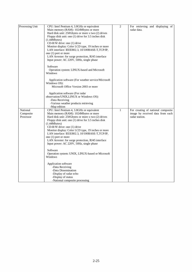
2-25
Processing Unit CPU: Intel Pentium 4, 3.8GHz or equivalent Main memory (RAM): 1024Mbytes or more Hard disk unit: 250Gbytes or more x two (2) drives Floppy disk unit: one (1) drive for 3.5 inches disk
(1.44Mbytes) CD-R/W drive: one (1) drive Monitor display: Color LCD type, 19 inches or more LAN interface: IEEE802.3, 10/100BASE-T,TCP/IP,
one (1) port or more LAN Arrester: for surge protection, RJ45 interface Input power: AC 220V, 50Hz, single phase Software
Operation system: LINUX-based and Microsoft Windows
Application software (For weather service/Microsoft Windows OS):
Microsoft Office Version 2003 or more
Application software (For radar observation/UNIX,LINUX or Windows OS):
-Data Receiving -Various weather products retrieving -Map edition
2 For retrieving and displaying of radar data.
National Composite Processor
CPU: Intel Pentium 4, 3.8GHz or equivalent Main memory (RAM): 1024Mbytes or more Hard disk unit: 250Gbytes or more x two (2) drives Floppy disk unit: one (1) drive for 3.5 inches disk
(1.44Mbytes) CD-R/W drive: one (1) drive Monitor display: Color LCD type, 19 inches or more LAN interface: IEEE802.3, 10/100BASE-T,TCP/IP,
one (1) port or more LAN Arrester: for surge protection, RJ45 interface Input power: AC 220V, 50Hz, single phase Software Operation system: UNIX, LINUX-based or Microsoft
Windows Application software
-Data Receiving -Data Dissemination -Display of radar echo -Display of status -National composite processing
1 For creating of national composite image by received data from each radar station.
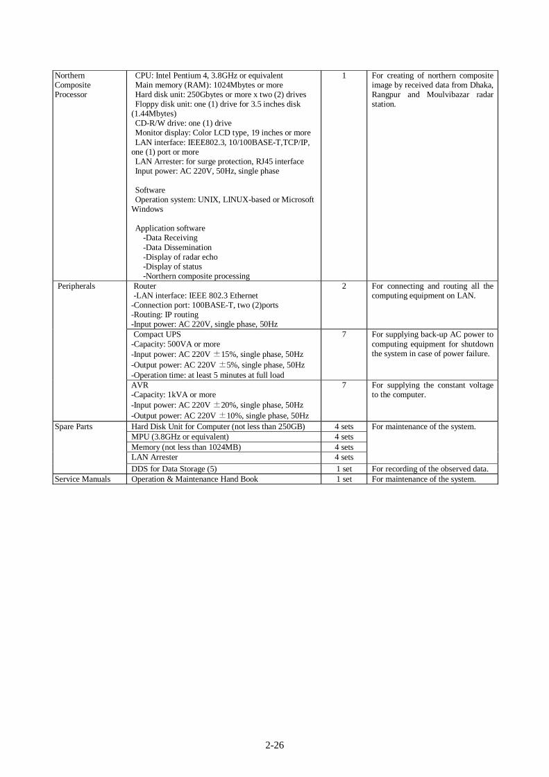
2-26
Northern Composite Processor
CPU: Intel Pentium 4, 3.8GHz or equivalent Main memory (RAM): 1024Mbytes or more Hard disk unit: 250Gbytes or more x two (2) drives Floppy disk unit: one (1) drive for 3.5 inches disk
(1.44Mbytes) CD-R/W drive: one (1) drive Monitor display: Color LCD type, 19 inches or more LAN interface: IEEE802.3, 10/100BASE-T,TCP/IP,
one (1) port or more LAN Arrester: for surge protection, RJ45 interface Input power: AC 220V, 50Hz, single phase Software Operation system: UNIX, LINUX-based or Microsoft
Windows Application software
-Data Receiving -Data Dissemination -Display of radar echo -Display of status -Northern composite processing
1 For creating of northern composite image by received data from Dhaka, Rangpur and Moulvibazar radar station.
Router -LAN interface: IEEE 802.3 Ethernet
-Connection port: 100BASE-T, two (2)ports -Routing: IP routing -Input power: AC 220V, single phase, 50Hz
2 For connecting and routing all the computing equipment on LAN.
Compact UPS -Capacity: 500VA or more -Input power: AC 220V ±15%, single phase, 50Hz -Output power: AC 220V ±5%, single phase, 50Hz -Operation time: at least 5 minutes at full load
7 For supplying back-up AC power to computing equipment for shutdown the system in case of power failure.
Peripherals
AVR -Capacity: 1kVA or more -Input power: AC 220V ±20%, single phase, 50Hz -Output power: AC 220V ±10%, single phase, 50Hz
7 For supplying the constant voltage to the computer.
Hard Disk Unit for Computer (not less than 250GB) 4 sets MPU (3.8GHz or equivalent) 4 sets Memory (not less than 1024MB) 4 sets LAN Arrester 4 sets
For maintenance of the system. Spare Parts
DDS for Data Storage (5) 1 set For recording of the observed data. Service Manuals Operation & Maintenance Hand Book 1 set For maintenance of the system.
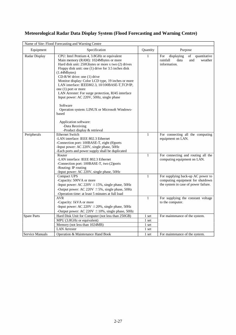
2-27
Meteorological Radar Data Display System (Flood Forecasting and Warning Centre) Name of Site: Flood Forecasting and Warning Centre
Equipment Specification Quantity Purpose
Radar Display CPU: Intel Pentium 4, 3.8GHz or equivalent Main memory (RAM): 1024Mbytes or more Hard disk unit: 250Gbytes or more x two (2) drives Floppy disk unit: one (1) drive for 3.5 inches disk
(1.44Mbytes) CD-R/W drive: one (1) drive Monitor display: Color LCD type, 19 inches or more LAN interface: IEEE802.3, 10/100BASE-T,TCP/IP,
one (1) port or more LAN Arrester: For surge protection, RJ45 interface Input power: AC 220V, 50Hz, single phase Software Operation system: LINUX or Microsoft Windows-
based Application software:
-Data Receiving -Product display & retrieval
1 For displaying of quantitative rainfall data and weather information.
Ethernet Switch -LAN interface: IEEE 802.3 Ethernet -Connection port: 100BASE-T, eight (8)ports -Input power: AC 220V, single phase, 50Hz -Each ports and power supply shall be duplicated
1 For connecting all the computing equipment on LAN.
Router -LAN interface: IEEE 802.3 Ethernet
-Connection port: 100BASE-T, two (2)ports -Routing: IP routing -Input power: AC 220V, single phase, 50Hz
1 For connecting and routing all the computing equipment on LAN.
Compact UPS -Capacity: 500VA or more -Input power: AC 220V ±15%, single phase, 50Hz -Output power: AC 220V ±5%, single phase, 50Hz -Operation time: at least 5 minutes at full load
1 For supplying back-up AC power to computing equipment for shutdown the system in case of power failure.
Peripherals
AVR -Capacity: 1kVA or more -Input power: AC 220V ±20%, single phase, 50Hz -Output power: AC 220V ±10%, single phase, 50Hz
1 For supplying the constant voltage to the computer.
Hard Disk Unit for Computer (not less than 250GB) 1 set MPU (3.8GHz or equivalent) 1 set Memory (not less than 1024MB) 1 set
Spare Parts
LAN Arrester 1 set
For maintenance of the system.
Service Manuals Operation & Maintenance Hand Book 1 set For maintenance of the system.
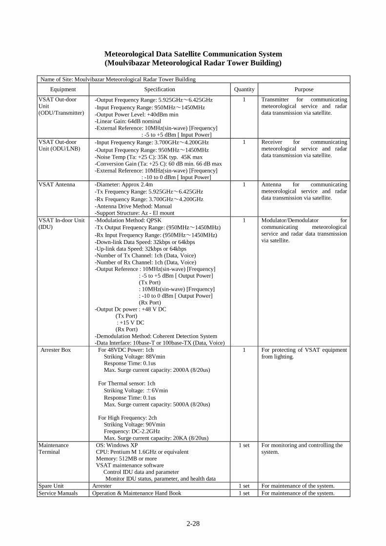
2-28
Meteorological Data Satellite Communication System (Moulvibazar Meteorological Radar Tower Building)
Name of Site: Moulvibazar Meteorological Radar Tower Building
Equipment Specification Quantity Purpose
VSAT Out-door Unit (ODU/Transmitter)
-Output Frequency Range: 5.925GHz~6.425GHz -Input Frequency Range: 950MHz~1450MHz -Output Power Level: +40dBm min -Linear Gain: 64dB nominal -External Reference: 10MHz(sin-wave) [Frequency]
: -5 to +5 dBm [ Input Power]
1 Transmitter for communicating meteorological service and radar data transmission via satellite.
VSAT Out-door Unit (ODU/LNB)
-Input Frequency Range: 3.700GHz~4.200GHz -Output Frequency Range: 950MHz~1450MHz -Noise Temp (Ta: +25 C): 35K typ. 45K max -Conversion Gain (Ta: +25 C): 60 dB min. 66 dB max -External Reference: 10MHz(sin-wave) [Frequency]
: -10 to 0 dBm [ Input Power]
1 Receiver for communicating meteorological service and radar data transmission via satellite.
VSAT Antenna -Diameter: Approx 2.4m -Tx Frequency Range: 5.925GHz~6.425GHz -Rx Frequency Range: 3.700GHz~4.200GHz -Antenna Drive Method: Manual -Support Structure: Az - El mount
1 Antenna for communicating meteorological service and radar data transmission via satellite.
VSAT In-door Unit (IDU)
-Modulation Method: QPSK -Tx Output Frequency Range: (950MHz~1450MHz) -Rx Input Frequency Range: (950MHz~1450MHz) -Down-link Data Speed: 32kbps or 64kbps -Up-link data Speed: 32kbps or 64kbps -Number of Tx Channel: 1ch (Data, Voice) -Number of Rx Channel: 1ch (Data, Voice) -Output Reference : 10MHz(sin-wave) [Frequency]
: -5 to +5 dBm [ Output Power] (Tx Port) : 10MHz(sin-wave) [Frequency] : -10 to 0 dBm [ Output Power] (Rx Port)
-Output Dc power : +48 V DC (Tx Port) : +15 V DC
(Rx Port) -Demodulation Method: Coherent Detection System -Data Interface: 10base-T or 100base-TX (Data, Voice)
1 Modulator/Demodulator forcommunicating meteorologicalservice and radar data transmission via satellite.
Arrester Box For 48VDC Power: 1ch Striking Voltage: 88Vmin Response Time: 0.1us Max. Surge current capacity: 2000A (8/20us)
For Thermal sensor: 1ch
Striking Voltage: ±6Vmin Response Time: 0.1us Max. Surge current capacity: 5000A (8/20us)
For High Frequency: 2ch
Striking Voltage: 90Vmin Frequency: DC-2.2GHz Max. Surge current capacity: 20KA (8/20us)
1 For protecting of VSAT equipment from lighting.
Maintenance Terminal
OS: Windows XP CPU: Pentium M 1.6GHz or equivalent Memory: 512MB or more VSAT maintenance software Control IDU data and parameter
Monitor IDU status, parameter, and health data
1 set For monitoring and controlling the system.
Spare Unit Arrester 1 set For maintenance of the system. Service Manuals Operation & Maintenance Hand Book 1 set For maintenance of the system.
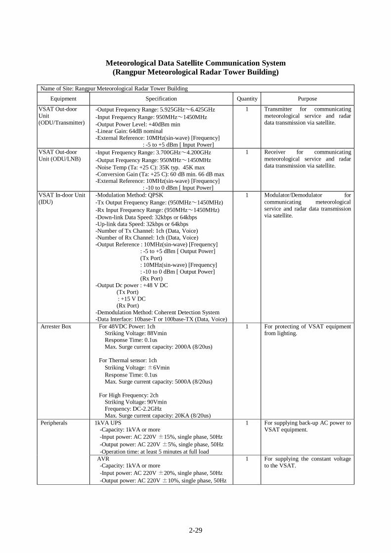
2-29
Meteorological Data Satellite Communication System
(Rangpur Meteorological Radar Tower Building) Name of Site: Rangpur Meteorological Radar Tower Building
Equipment Specification Quantity Purpose
VSAT Out-door Unit (ODU/Transmitter)
-Output Frequency Range: 5.925GHz~6.425GHz -Input Frequency Range: 950MHz~1450MHz -Output Power Level: +40dBm min -Linear Gain: 64dB nominal -External Reference: 10MHz(sin-wave) [Frequency]
: -5 to +5 dBm [ Input Power]
1 Transmitter for communicating meteorological service and radar data transmission via satellite.
VSAT Out-door Unit (ODU/LNB)
-Input Frequency Range: 3.700GHz~4.200GHz -Output Frequency Range: 950MHz~1450MHz -Noise Temp (Ta: +25 C): 35K typ. 45K max -Conversion Gain (Ta: +25 C): 60 dB min. 66 dB max -External Reference: 10MHz(sin-wave) [Frequency]
: -10 to 0 dBm [ Input Power]
1 Receiver for communicating meteorological service and radar data transmission via satellite.
VSAT In-door Unit (IDU)
-Modulation Method: QPSK -Tx Output Frequency Range: (950MHz~1450MHz) -Rx Input Frequency Range: (950MHz~1450MHz) -Down-link Data Speed: 32kbps or 64kbps -Up-link data Speed: 32kbps or 64kbps -Number of Tx Channel: 1ch (Data, Voice) -Number of Rx Channel: 1ch (Data, Voice) -Output Reference : 10MHz(sin-wave) [Frequency]
: -5 to +5 dBm [ Output Power] (Tx Port) : 10MHz(sin-wave) [Frequency] : -10 to 0 dBm [ Output Power] (Rx Port)
-Output Dc power : +48 V DC (Tx Port) : +15 V DC
(Rx Port) -Demodulation Method: Coherent Detection System -Data Interface: 10base-T or 100base-TX (Data, Voice)
1 Modulator/Demodulator forcommunicating meteorologicalservice and radar data transmission via satellite.
Arrester Box For 48VDC Power: 1ch Striking Voltage: 88Vmin Response Time: 0.1us Max. Surge current capacity: 2000A (8/20us)
For Thermal sensor: 1ch
Striking Voltage: ±6Vmin Response Time: 0.1us Max. Surge current capacity: 5000A (8/20us)
For High Frequency: 2ch
Striking Voltage: 90Vmin Frequency: DC-2.2GHz Max. Surge current capacity: 20KA (8/20us)
1 For protecting of VSAT equipment from lighting.
1kVA UPS -Capacity: 1kVA or more -Input power: AC 220V ±15%, single phase, 50Hz -Output power: AC 220V ±5%, single phase, 50Hz -Operation time: at least 5 minutes at full load
1 For supplying back-up AC power to VSAT equipment.
Peripherals
AVR -Capacity: 1kVA or more -Input power: AC 220V ±20%, single phase, 50Hz -Output power: AC 220V ±10%, single phase, 50Hz
1 For supplying the constant voltage to the VSAT.
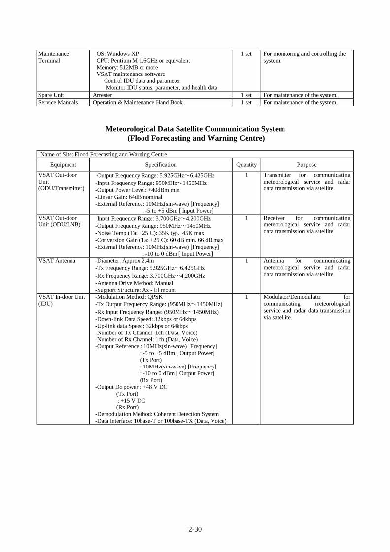
2-30
Maintenance Terminal
OS: Windows XP CPU: Pentium M 1.6GHz or equivalent Memory: 512MB or more VSAT maintenance software Control IDU data and parameter
Monitor IDU status, parameter, and health data
1 set For monitoring and controlling the system.
Spare Unit Arrester 1 set For maintenance of the system. Service Manuals Operation & Maintenance Hand Book 1 set For maintenance of the system.
Meteorological Data Satellite Communication System (Flood Forecasting and Warning Centre)
Name of Site: Flood Forecasting and Warning Centre
Equipment Specification Quantity Purpose
VSAT Out-door Unit (ODU/Transmitter)
-Output Frequency Range: 5.925GHz~6.425GHz -Input Frequency Range: 950MHz~1450MHz -Output Power Level: +40dBm min -Linear Gain: 64dB nominal -External Reference: 10MHz(sin-wave) [Frequency]
: -5 to +5 dBm [ Input Power]
1 Transmitter for communicating meteorological service and radar data transmission via satellite.
VSAT Out-door Unit (ODU/LNB)
-Input Frequency Range: 3.700GHz~4.200GHz -Output Frequency Range: 950MHz~1450MHz -Noise Temp (Ta: +25 C): 35K typ. 45K max -Conversion Gain (Ta: +25 C): 60 dB min. 66 dB max -External Reference: 10MHz(sin-wave) [Frequency]
: -10 to 0 dBm [ Input Power]
1 Receiver for communicating meteorological service and radar data transmission via satellite.
VSAT Antenna -Diameter: Approx 2.4m -Tx Frequency Range: 5.925GHz~6.425GHz -Rx Frequency Range: 3.700GHz~4.200GHz -Antenna Drive Method: Manual -Support Structure: Az - El mount
1 Antenna for communicating meteorological service and radar data transmission via satellite.
VSAT In-door Unit (IDU)
-Modulation Method: QPSK -Tx Output Frequency Range: (950MHz~1450MHz) -Rx Input Frequency Range: (950MHz~1450MHz) -Down-link Data Speed: 32kbps or 64kbps -Up-link data Speed: 32kbps or 64kbps -Number of Tx Channel: 1ch (Data, Voice) -Number of Rx Channel: 1ch (Data, Voice) -Output Reference : 10MHz(sin-wave) [Frequency]
: -5 to +5 dBm [ Output Power] (Tx Port) : 10MHz(sin-wave) [Frequency] : -10 to 0 dBm [ Output Power] (Rx Port)
-Output Dc power : +48 V DC (Tx Port) : +15 V DC
(Rx Port) -Demodulation Method: Coherent Detection System -Data Interface: 10base-T or 100base-TX (Data, Voice)
1 Modulator/Demodulator forcommunicating meteorologicalservice and radar data transmission via satellite.
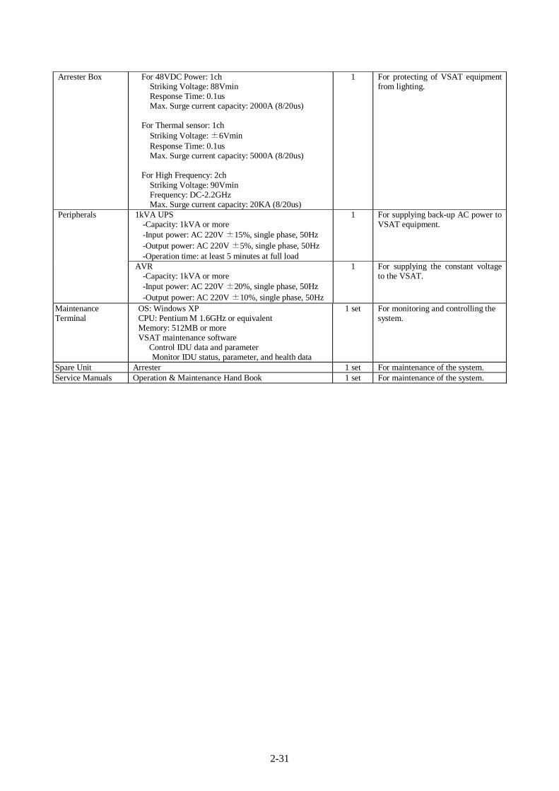
2-31
Arrester Box For 48VDC Power: 1ch Striking Voltage: 88Vmin Response Time: 0.1us Max. Surge current capacity: 2000A (8/20us)
For Thermal sensor: 1ch
Striking Voltage: ±6Vmin Response Time: 0.1us Max. Surge current capacity: 5000A (8/20us)
For High Frequency: 2ch
Striking Voltage: 90Vmin Frequency: DC-2.2GHz Max. Surge current capacity: 20KA (8/20us)
1 For protecting of VSAT equipment from lighting.
1kVA UPS -Capacity: 1kVA or more -Input power: AC 220V ±15%, single phase, 50Hz -Output power: AC 220V ±5%, single phase, 50Hz -Operation time: at least 5 minutes at full load
1 For supplying back-up AC power to VSAT equipment.
Peripherals
AVR -Capacity: 1kVA or more -Input power: AC 220V ±20%, single phase, 50Hz -Output power: AC 220V ±10%, single phase, 50Hz
1 For supplying the constant voltage to the VSAT.
Maintenance Terminal
OS: Windows XP CPU: Pentium M 1.6GHz or equivalent Memory: 512MB or more VSAT maintenance software Control IDU data and parameter
Monitor IDU status, parameter, and health data
1 set For monitoring and controlling the system.
Spare Unit Arrester 1 set For maintenance of the system. Service Manuals Operation & Maintenance Hand Book 1 set For maintenance of the system.

2-32
Meteorological Data Satellite Communication System (Dhaka Head Office, Strom Warning Centre)
Name of Site: Dhaka Strom Warning Centre
Equipment Specification Quantity Purpose
HUB In-door Unit (IDU)
-Modulation Method: QPSK -Tx Output Frequency Range: (950MHz~1450MHz) -Rx Input Frequency Range: (950MHz~1450MHz) -Down-link Data Speed: 32kbps or 64kbps -Up-link data Speed: 32kbps -Number of Tx Channel: 3ch (Data, Voice) -Number of Rx Channel: 3ch (Data, Voice) -Connectable with the Dhaka existing Comstream DT-8000 for communicating with Rangpur Meteorological Radar
-Output Reference : 10MHz(sin-wave) [Frequency] : -5 to +5 dBm [ Output Power] (Tx Port) : 10MHz(sin-wave) [Frequency] : -10 to 0 dBm [ Output Power] (Rx Port)
-Output Dc power : +48 V DC (Tx Port) : +15 V DC
(Rx Port) -Demodulation Method: Coherent Detection System -Data Interface: 10base-T or 100base-TX (Data, Voice)-Equipment Rack: 19 inch Rack -Power Consumption: 800VA or less including ODU
1 Modulator/Demodulator for communicating meteorological service and radar data transmission via satellite.
Maintenance Terminal
OS: Windows XP CPU: Pentium M 1.6GHz or equivalent Memory: 512MB or more VSAT maintenance software Control IDU data and parameter
Monitor IDU status, parameter, and health data
1 set For monitoring and controlling the system.
Spare Unit Combiner/Divider 1 set For maintenance of the system. Service Manuals Operation & Maintenance Hand Book 1 set For maintenance of the system.
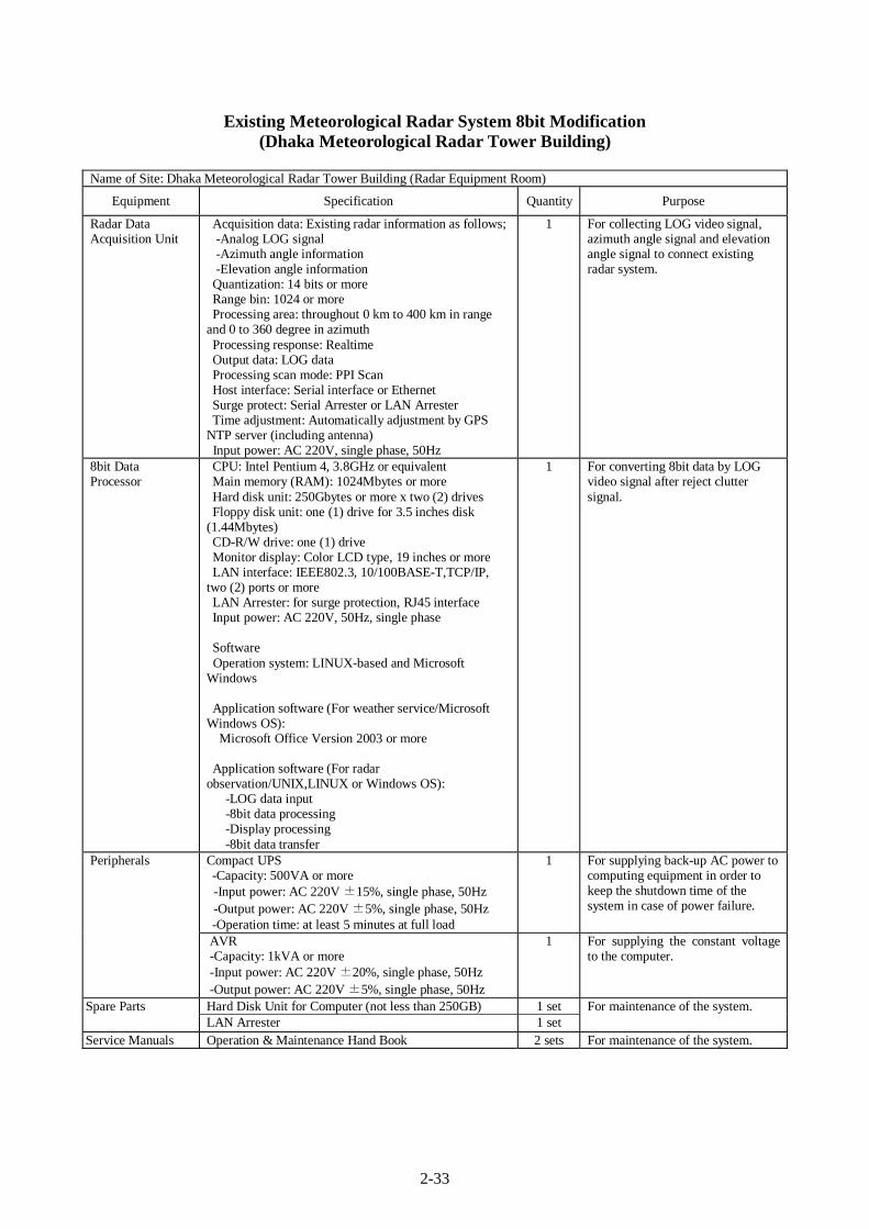
2-33
Existing Meteorological Radar System 8bit Modification (Dhaka Meteorological Radar Tower Building)
Name of Site: Dhaka Meteorological Radar Tower Building (Radar Equipment Room)
Equipment Specification Quantity Purpose
Radar Data Acquisition Unit
Acquisition data: Existing radar information as follows; -Analog LOG signal -Azimuth angle information -Elevation angle information Quantization: 14 bits or more Range bin: 1024 or more Processing area: throughout 0 km to 400 km in range
and 0 to 360 degree in azimuth Processing response: Realtime Output data: LOG data Processing scan mode: PPI Scan Host interface: Serial interface or Ethernet Surge protect: Serial Arrester or LAN Arrester Time adjustment: Automatically adjustment by GPS
NTP server (including antenna) Input power: AC 220V, single phase, 50Hz
1 For collecting LOG video signal, azimuth angle signal and elevation angle signal to connect existing radar system.
8bit Data Processor
CPU: Intel Pentium 4, 3.8GHz or equivalent Main memory (RAM): 1024Mbytes or more Hard disk unit: 250Gbytes or more x two (2) drives Floppy disk unit: one (1) drive for 3.5 inches disk
(1.44Mbytes) CD-R/W drive: one (1) drive Monitor display: Color LCD type, 19 inches or more LAN interface: IEEE802.3, 10/100BASE-T,TCP/IP,
two (2) ports or more LAN Arrester: for surge protection, RJ45 interface Input power: AC 220V, 50Hz, single phase Software Operation system: LINUX-based and Microsoft
Windows Application software (For weather service/Microsoft
Windows OS): Microsoft Office Version 2003 or more Application software (For radar
observation/UNIX,LINUX or Windows OS): -LOG data input -8bit data processing -Display processing -8bit data transfer
1 For converting 8bit data by LOG video signal after reject clutter signal.
Compact UPS -Capacity: 500VA or more -Input power: AC 220V ±15%, single phase, 50Hz -Output power: AC 220V ±5%, single phase, 50Hz -Operation time: at least 5 minutes at full load
1 For supplying back-up AC power to computing equipment in order to keep the shutdown time of the system in case of power failure.
Peripherals
AVR -Capacity: 1kVA or more -Input power: AC 220V ±20%, single phase, 50Hz -Output power: AC 220V ±5%, single phase, 50Hz
1 For supplying the constant voltage to the computer.
Hard Disk Unit for Computer (not less than 250GB) 1 set Spare Parts LAN Arrester 1 set
For maintenance of the system.
Service Manuals Operation & Maintenance Hand Book 2 sets For maintenance of the system.
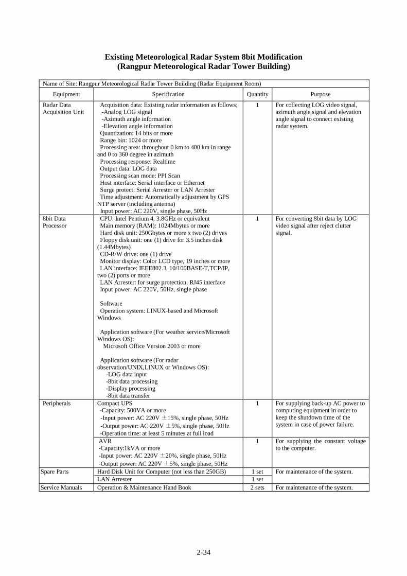
2-34
Existing Meteorological Radar System 8bit Modification (Rangpur Meteorological Radar Tower Building)
Name of Site: Rangpur Meteorological Radar Tower Building (Radar Equipment Room)
Equipment Specification Quantity Purpose
Radar Data Acquisition Unit
Acquisition data: Existing radar information as follows; -Analog LOG signal -Azimuth angle information -Elevation angle information Quantization: 14 bits or more Range bin: 1024 or more Processing area: throughout 0 km to 400 km in range
and 0 to 360 degree in azimuth Processing response: Realtime Output data: LOG data Processing scan mode: PPI Scan Host interface: Serial interface or Ethernet Surge protect: Serial Arrester or LAN Arrester Time adjustment: Automatically adjustment by GPS
NTP server (including antenna) Input power: AC 220V, single phase, 50Hz
1 For collecting LOG video signal, azimuth angle signal and elevation angle signal to connect existing radar system.
8bit Data Processor
CPU: Intel Pentium 4, 3.8GHz or equivalent Main memory (RAM): 1024Mbytes or more Hard disk unit: 250Gbytes or more x two (2) drives Floppy disk unit: one (1) drive for 3.5 inches disk
(1.44Mbytes) CD-R/W drive: one (1) drive Monitor display: Color LCD type, 19 inches or more LAN interface: IEEE802.3, 10/100BASE-T,TCP/IP,
two (2) ports or more LAN Arrester: for surge protection, RJ45 interface Input power: AC 220V, 50Hz, single phase Software Operation system: LINUX-based and Microsoft
Windows Application software (For weather service/Microsoft
Windows OS): Microsoft Office Version 2003 or more Application software (For radar
observation/UNIX,LINUX or Windows OS): -LOG data input -8bit data processing -Display processing -8bit data transfer
1 For converting 8bit data by LOG video signal after reject clutter signal.
Compact UPS -Capacity: 500VA or more -Input power: AC 220V ±15%, single phase, 50Hz -Output power: AC 220V ±5%, single phase, 50Hz -Operation time: at least 5 minutes at full load
1 For supplying back-up AC power to computing equipment in order to keep the shutdown time of the system in case of power failure.
Peripherals
AVR -Capacity:1kVA or more -Input power: AC 220V ±20%, single phase, 50Hz -Output power: AC 220V ±5%, single phase, 50Hz
1 For supplying the constant voltage to the computer.
Hard Disk Unit for Computer (not less than 250GB) 1 set Spare Parts LAN Arrester 1 set
For maintenance of the system.
Service Manuals Operation & Maintenance Hand Book 2 sets For maintenance of the system.
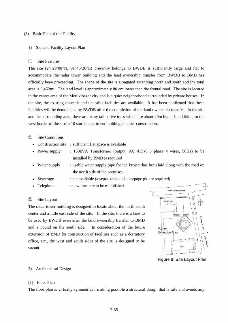
2-35
(3) Basic Plan of the Facility
1) Site and Facility Layout Plan ① Site Features The site (24°29’08”N, 91°46’30”E) presently belongs to BWDB is sufficiently large and flat to accommodate the radar tower building and the land ownership transfer from BWDB to BMD has officially been proceeding. The shape of the site is elongated extending north and south and the total area is 3,452m2. The land level is approximately 80 cm lower than the frontal road. The site is located in the center area of the Moulvibazar city and is a quiet neighborhood surrounded by private houses. In the site, the existing decrepit and unusable facilities are available. It has been confirmed that these facilities will be demolished by BWDB after the completion of the land ownership transfer. In the site and the surrounding area, there are many tall native trees which are about 20m high. In addition, to the west border of the site, a 10 storied apartment building is under construction.
② Site Conditions
• Construction site : sufficient flat space is available • Power supply : 150kVA Transformer (output: AC 415V, 3 phase 4 wires, 50Hz) to be
installed by BMD is required • Water supply : usable water supply pipe for the Project has been laid along with the road on
the north side of the premises • Sewerage : not available (a septic tank and a seepage pit are required) • Telephone : new lines are to be established
③ Site Layout The radar tower building is designed to locate about the north-south center and a little east side of the site. In the site, there is a land to be used by BWDB even after the land ownership transfer to BMD and a pound on the south side. In consideration of the future extension of BMD for construction of facilities such as a dormitory office, etc., the west and south sides of the site is designed to be vacant.
2) Architectural Design
[1] Floor Plan The floor plan is virtually symmetrical, making possible a structural design that is safe and avoids any
Future
Extension Area
Figure 9: Site Layout Plan

2-36
kind of eccentricity. The floor plan for the central portion of the radar tower building allows the various rooms to be arranged with great flexibility, since there are no structures such as columns and beams protruding into the internal staircase (which is also to serve as an evacuation route). Construction methods and materials follow local practice and the building is of standard grade in Bangladesh. The following table shows total floor area of the radar tower building constructed in recent years by the Japan’s Grant Aid and the Moulvibazar which is a standard size.
Table 16: Floor Area of Radar Tower Buildings (by the Japan’s Grant Aid Assistance)
Radar Tower Building Lao, Vientiane Cox’s Bazar Khepupara Moulvibazar Total Floor Area 309.97m2 323.35 m2 350.81 m2 350.06 m2
The floor area of each room, the number of working staff, the room’s function and the method of calculation of the size of each room are shown in the following tables.
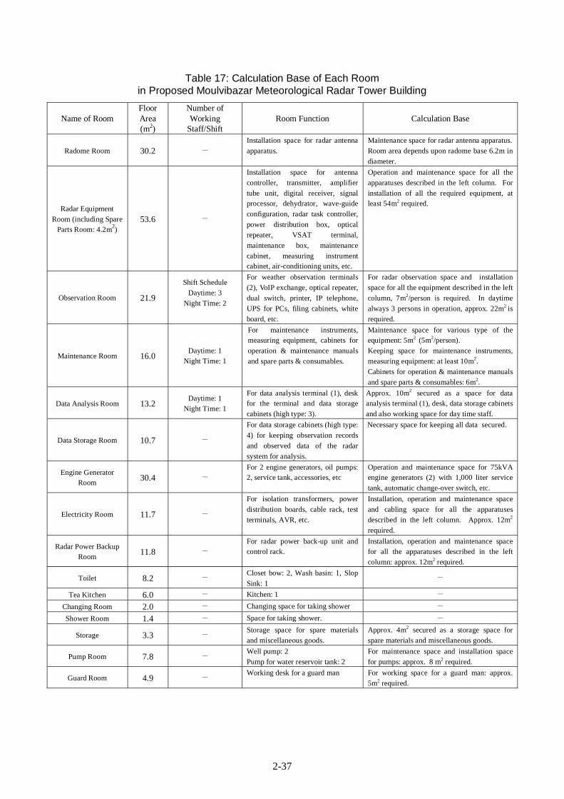
2-37
Table 17: Calculation Base of Each Room in Proposed Moulvibazar Meteorological Radar Tower Building
Name of Room Floor Area (m2)
Number of Working
Staff/Shift Room Function Calculation Base
Radome Room 30.2 - Installation space for radar antenna apparatus.
Maintenance space for radar antenna apparatus. Room area depends upon radome base 6.2m in diameter.
Radar Equipment Room (including Spare
Parts Room: 4.2m2) 53.6 -
Installation space for antenna controller, transmitter, amplifier tube unit, digital receiver, signal processor, dehydrator, wave-guide configuration, radar task controller, power distribution box, optical repeater, VSAT terminal, maintenance box, maintenance cabinet, measuring instrument cabinet, air-conditioning units, etc.
Operation and maintenance space for all the apparatuses described in the left column. For installation of all the required equipment, at least 54m2 required.
Observation Room 21.9
Shift Schedule Daytime: 3
Night Time: 2
For weather observation terminals (2), VoIP exchange, optical repeater, dual switch, printer, IP telephone, UPS for PCs, filing cabinets, white board, etc.
For radar observation space and installation space for all the equipment described in the left column, 7m2/person is required. In daytime always 3 persons in operation, approx. 22m2 is required.
Maintenance Room 16.0 Daytime: 1
Night Time: 1
For maintenance instruments, measuring equipment, cabinets for operation & maintenance manuals and spare parts & consumables.
Maintenance space for various type of the equipment: 5m2 (5m2/person). Keeping space for maintenance instruments, measuring equipment: at least 10m2.
Cabinets for operation & maintenance manuals and spare parts & consumables: 6m2.
Data Analysis Room 13.2 Daytime: 1
Night Time: 1
For data analysis terminal (1), desk for the terminal and data storage cabinets (high type: 3).
Approx. 10m2 secured as a space for data analysis terminal (1), desk, data storage cabinets and also working space for day time staff.
Data Storage Room 10.7 -
For data storage cabinets (high type: 4) for keeping observation records and observed data of the radar system for analysis.
Necessary space for keeping all data secured.
Engine Generator Room 30.4 -
For 2 engine generators, oil pumps: 2, service tank, accessories, etc
Operation and maintenance space for 75kVA engine generators (2) with 1,000 liter service tank, automatic change-over switch, etc.
Electricity Room 11.7 -
For isolation transformers, power distribution boards, cable rack, test terminals, AVR, etc.
Installation, operation and maintenance space and cabling space for all the apparatuses described in the left column. Approx. 12m2 required.
Radar Power Backup Room 11.8 -
For radar power back-up unit and control rack.
Installation, operation and maintenance space for all the apparatuses described in the left column: approx. 12m2 required.
Toilet 8.2 - Closet bow: 2, Wash basin: 1, Slop Sink: 1
-
Tea Kitchen 6.0 - Kitchen: 1 - Changing Room 2.0 - Changing space for taking shower - Shower Room 1.4 - Space for taking shower. -
Storage 3.3 - Storage space for spare materials and miscellaneous goods.
Approx. 4m2 secured as a storage space for spare materials and miscellaneous goods.
Pump Room 7.8 - Well pump: 2 Pump for water reservoir tank: 2
For maintenance space and installation space for pumps: approx. 8 m2 required.
Guard Room 4.9 - Working desk for a guard man For working space for a guard man: approx. 5m2 required.
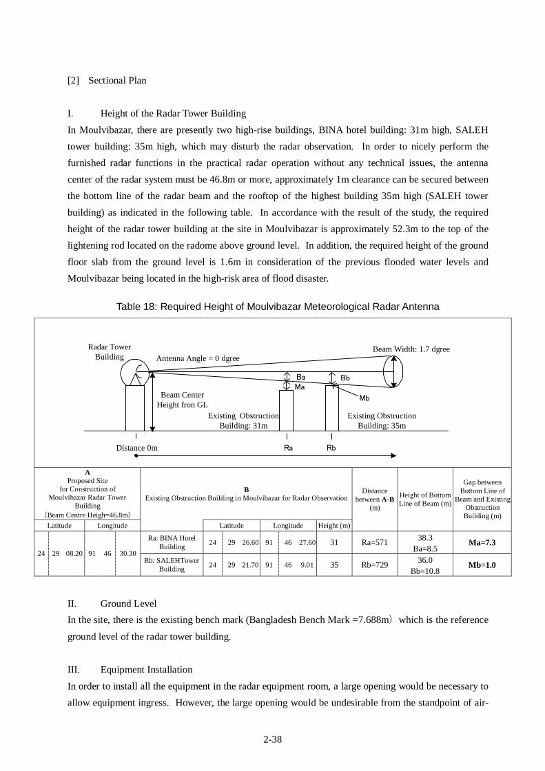
2-38
[2] Sectional Plan I. Height of the Radar Tower Building In Moulvibazar, there are presently two high-rise buildings, BINA hotel building: 31m high, SALEH tower building: 35m high, which may disturb the radar observation. In order to nicely perform the furnished radar functions in the practical radar operation without any technical issues, the antenna center of the radar system must be 46.8m or more, approximately 1m clearance can be secured between the bottom line of the radar beam and the rooftop of the highest building 35m high (SALEH tower building) as indicated in the following table. In accordance with the result of the study, the required height of the radar tower building at the site in Moulvibazar is approximately 52.3m to the top of the lightening rod located on the radome above ground level. In addition, the required height of the ground floor slab from the ground level is 1.6m in consideration of the previous flooded water levels and Moulvibazar being located in the high-risk area of flood disaster.
Table 18: Required Height of Moulvibazar Meteorological Radar Antenna
A Proposed Site
for Construction of Moulvibazar Radar Tower
Building (Beam Centre Heigh=46.8m)
B Existing Obstruction Building in Moulvibazar for Radar Observation
Latitude Longitude Latitude Longitude Height (m)
Distance between A-B
(m)
Height of Bottom Line of Beam (m)
Gap between Bottom Line of
Beam and Existing Obstruction Building (m)
Ra: BINA Hotel Building 24 29 26.60 91 46 27.60 31 Ra=571 38.3
Ba=8.5 Ma=7.3
24 29 08.20 91 46 30.30 Rb: SALEHTower
Building 24 29 21.70 91 46 9.01 35 Rb=729 36.0 Bb=10.8
Mb=1.0
II. Ground Level In the site, there is the existing bench mark (Bangladesh Bench Mark =7.688m)which is the reference
ground level of the radar tower building.
III. Equipment Installation In order to install all the equipment in the radar equipment room, a large opening would be necessary to allow equipment ingress. However, the large opening would be undesirable from the standpoint of air-
Ra RbDistance 0m
Beam CenterHeight fron GL
Existing ObstructionBuilding: 31m
Radar TowerBuilding Antenna Angle = 0 dgree
Ba Bb
Existing ObstructionBuilding: 35m
Ma
Mb
Beam Width: 1.7 dgree
2-39
tightness and dust proofing. The equipment will, therefore, be brought in via a loading balcony at the adjacent staircase room. For lifting the equipment, a lifting hook with a capacity of 2-tons will be installed on the upper part of this balcony.
[3] Elevation Plan The structural columns and beams will extend outside the building, enhancing the building design. Because of this, since columns and beams will not intrude into the staircase, the staircase will be able to comfortably handle traffic in both directions.
[4] Construction Method The structural beams, external stairs, floor slabs, elevated parapet walls (observation deck and radome) will be made by the cast-in-place pre-cast concrete construction method. This construction method will shorten the construction period by 13 months. In case that the normal concrete construction method is applied, the construction period is estimated 14.5 months. Considering 6 months of the equipment installation period, it is rather difficult to complete the Project in the stated implementation period of in the Exchange of Notes to be signed by both Governments. Therefore, use of the cast-in-place pre-cast concrete construction method for the Project is quite important. The structural member size and shape are unified as many as possible for effectively utilizing merits of the cast-in-place pre-cast concrete construction method.
[5] Internal and External Finishing Plan
I. Finishing of Major Rooms (Radar Observation Room and Observation Room)
a) Floor The radar equipment room and the observation room will have an access floor with a clearance of 15cm for easy wiring of power and signal cables, easy maintenance and easy future expansion. An antistatic, heavy-duty access floor has been selected for the radar equipment room in which a high power radar transmitter weighting about 1 ton is to be installed.
b) External Walls To combat the effects of local temperature and humidity, the external walls of the radar equipment room are designed as cavity walls in which glass wool is sandwiched for heat insulation. Because of the thermal insulation provided by the building design, the recurrent cost to BMD of power for air-conditioning systems will be minimized.
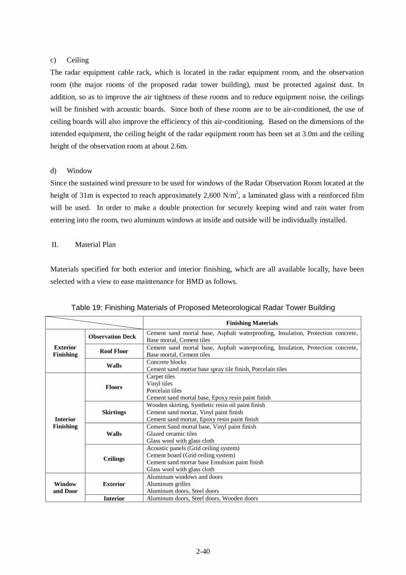
2-40
c) Ceiling The radar equipment cable rack, which is located in the radar equipment room, and the observation room (the major rooms of the proposed radar tower building), must be protected against dust. In addition, so as to improve the air tightness of these rooms and to reduce equipment noise, the ceilings will be finished with acoustic boards. Since both of these rooms are to be air-conditioned, the use of ceiling boards will also improve the efficiency of this air-conditioning. Based on the dimensions of the intended equipment, the ceiling height of the radar equipment room has been set at 3.0m and the ceiling height of the observation room at about 2.6m.
d) Window Since the sustained wind pressure to be used for windows of the Radar Observation Room located at the height of 31m is expected to reach approximately 2,600 N/m2, a laminated glass with a reinforced film will be used. In order to make a double protection for securely keeping wind and rain water from entering into the room, two aluminum windows at inside and outside will be individually installed.
II. Material Plan
Materials specified for both exterior and interior finishing, which are all available locally, have been selected with a view to ease maintenance for BMD as follows.
Table 19: Finishing Materials of Proposed Meteorological Radar Tower Building Finishing Materials
Observation Deck Cement sand mortal base, Asphalt waterproofing, Insulation, Protection concrete, Base mortal, Cement tiles
Roof Floor Cement sand mortal base, Asphalt waterproofing, Insulation, Protection concrete, Base mortal, Cement tiles
Exterior Finishing
Walls Concrete blocks Cement sand mortar base spray tile finish, Porcelain tiles
Floors
Carpet tiles Vinyl tiles Porcelain tiles Cement sand mortal base, Epoxy resin paint finish
Skirtings Wooden skirting, Synthetic resin oil paint finish Cement sand mortar, Vinyl paint finish Cement sand mortar, Epoxy resin paint finish
Walls Cement Sand mortal base, Vinyl paint finish Glazed ceramic tiles Glass wool with glass cloth
Interior Finishing
Ceilings
Acoustic panels (Grid ceiling system) Cement board (Grid ceiling system) Cement sand mortar base Emulsion paint finish Glass wool with glass cloth
Exterior Aluminum windows and doors Aluminum grilles Aluminum doors, Steel doors
Window and Door
Interior Aluminum doors, Steel doors, Wooden doors
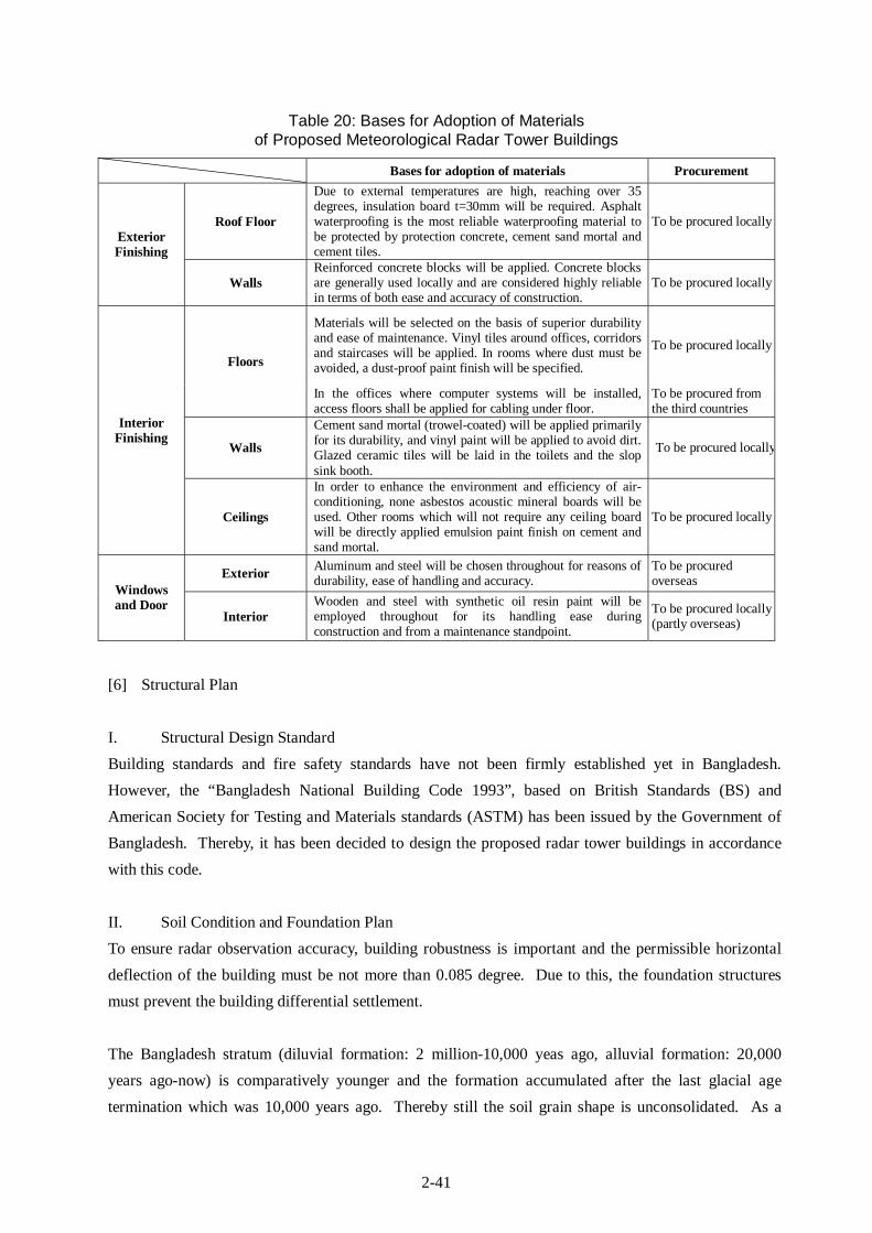
2-41
Table 20: Bases for Adoption of Materials of Proposed Meteorological Radar Tower Buildings
Bases for adoption of materials Procurement
Roof Floor
Due to external temperatures are high, reaching over 35 degrees, insulation board t=30mm will be required. Asphalt waterproofing is the most reliable waterproofing material to be protected by protection concrete, cement sand mortal and cement tiles.
To be procured locally Exterior Finishing
Walls Reinforced concrete blocks will be applied. Concrete blocks are generally used locally and are considered highly reliable in terms of both ease and accuracy of construction.
To be procured locally
Materials will be selected on the basis of superior durability and ease of maintenance. Vinyl tiles around offices, corridors and staircases will be applied. In rooms where dust must be avoided, a dust-proof paint finish will be specified.
To be procured locally Floors
In the offices where computer systems will be installed, access floors shall be applied for cabling under floor.
To be procured from the third countries
Walls
Cement sand mortal (trowel-coated) will be applied primarily for its durability, and vinyl paint will be applied to avoid dirt. Glazed ceramic tiles will be laid in the toilets and the slop sink booth.
To be procured locally
Interior Finishing
Ceilings
In order to enhance the environment and efficiency of air-conditioning, none asbestos acoustic mineral boards will be used. Other rooms which will not require any ceiling board will be directly applied emulsion paint finish on cement and sand mortal.
To be procured locally
Exterior Aluminum and steel will be chosen throughout for reasons of durability, ease of handling and accuracy.
To be procured overseas
Windows and Door
Interior Wooden and steel with synthetic oil resin paint will be employed throughout for its handling ease during construction and from a maintenance standpoint.
To be procured locally (partly overseas)
[6] Structural Plan I. Structural Design Standard Building standards and fire safety standards have not been firmly established yet in Bangladesh. However, the “Bangladesh National Building Code 1993”, based on British Standards (BS) and American Society for Testing and Materials standards (ASTM) has been issued by the Government of Bangladesh. Thereby, it has been decided to design the proposed radar tower buildings in accordance with this code.
II. Soil Condition and Foundation Plan To ensure radar observation accuracy, building robustness is important and the permissible horizontal deflection of the building must be not more than 0.085 degree. Due to this, the foundation structures must prevent the building differential settlement. The Bangladesh stratum (diluvial formation: 2 million-10,000 yeas ago, alluvial formation: 20,000 years ago-now) is comparatively younger and the formation accumulated after the last glacial age termination which was 10,000 years ago. Thereby still the soil grain shape is unconsolidated. As a
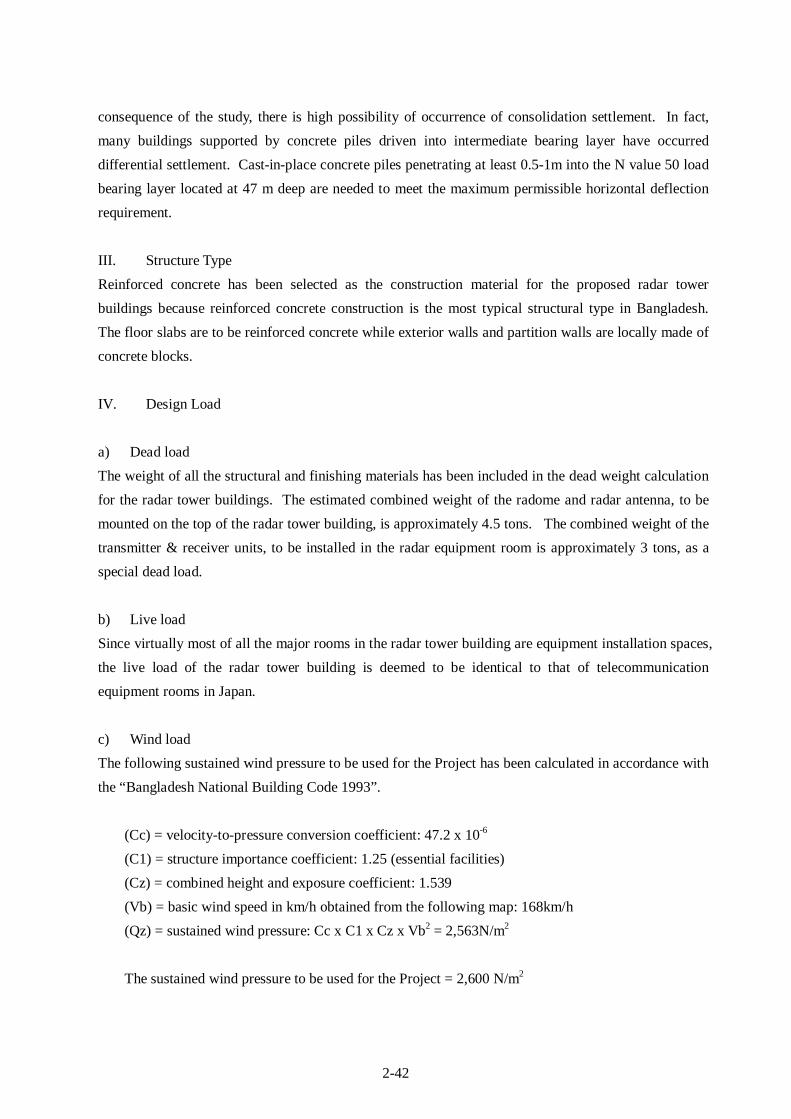
2-42
consequence of the study, there is high possibility of occurrence of consolidation settlement. In fact, many buildings supported by concrete piles driven into intermediate bearing layer have occurred differential settlement. Cast-in-place concrete piles penetrating at least 0.5-1m into the N value 50 load bearing layer located at 47 m deep are needed to meet the maximum permissible horizontal deflection requirement.
III. Structure Type Reinforced concrete has been selected as the construction material for the proposed radar tower buildings because reinforced concrete construction is the most typical structural type in Bangladesh. The floor slabs are to be reinforced concrete while exterior walls and partition walls are locally made of concrete blocks.
IV. Design Load a) Dead load The weight of all the structural and finishing materials has been included in the dead weight calculation for the radar tower buildings. The estimated combined weight of the radome and radar antenna, to be mounted on the top of the radar tower building, is approximately 4.5 tons. The combined weight of the transmitter & receiver units, to be installed in the radar equipment room is approximately 3 tons, as a special dead load. b) Live load Since virtually most of all the major rooms in the radar tower building are equipment installation spaces, the live load of the radar tower building is deemed to be identical to that of telecommunication equipment rooms in Japan.
c) Wind load The following sustained wind pressure to be used for the Project has been calculated in accordance with the “Bangladesh National Building Code 1993”.
(Cc) = velocity-to-pressure conversion coefficient: 47.2 x 10⁻⁶ (C1) = structure importance coefficient: 1.25 (essential facilities) (Cz) = combined height and exposure coefficient: 1.539 (Vb) = basic wind speed in km/h obtained from the following map: 168km/h (Qz) = sustained wind pressure: Cc x C1 x Cz x Vb2 = 2,563N/m2
The sustained wind pressure to be used for the Project = 2,600 N/m2
2-43
d) Seismic load According to the “Bangladesh National Building Code 1993”, Bangladesh is classified into three (3) seismic zones with seismic zone coefficients. Moulvibazar is located in Zone 3. The Basic Seismic Coefficient of Zone 3 is Z=0.25 which is equivalent to C=0.14 of the standardized shear coefficient specified in the Japan Building Code.
V. Structural Building Material All the materials for the building structure will be procured in Bangladesh. • Concrete : conventional concrete specified concrete strength Fc= 21N/mm2 • Cement : Japan Industrial Standard (JIS) or equivalent • Deformed reinforcing bars : ditto
[7] Electrical Facility Design
I. Power intake facility The required commercial power for the radar tower building will be stepped down to low-voltage by a new transformer (capacity: 150kVA, output: AC 415V, 3 phase 4 wires, 50Hz) to be installed by BMD at the site and will be connected through the existing power meters to the radar tower building. The power inlet to the radar tower building, including wiring and power connection to a low-voltage switchboard, through a hand-hole to be installed under the Project, is one of the major scopes of work to be undertaken by BMD at its own expense.
II. Power generating facility To ensure uninterrupted operation of the meteorological radar system and the other equipment, two engine generators with the following capacity are required for the radar tower building, as a back-up
Moulvibazar
Figure 10: Seismic Zoning Map ”Bangladesh National Building Code 1993”

2-44
power source during commercial power supply failures. During a flood, refueling for the engine generator is difficult. To ensure uninterrupted radar operation for 3 days a 1,000 liter service tank will be installed in the engine generator room of the building.
Capacity : 75 kVA Output : 415V, 3 phase 4 wire, 50 Hz
III. Trunk line and power facility Power will be distributed to the switchboard for lighting and to the electricity control panel from the distribution panel in the electrical room. The trunk line for distribution and the power line will use suitable cabling through conduits. An alarm for the power equipment will be shown on an alarm panel in the observation room. The electrical systems for the trunk line and branch circuits are as follows.
• Trunk line for lighting and power : 415V/240V, 3 phase 4 wire • Branch power circuits : 415V, 3 phase 4 wire • Branch lighting circuits : 240V, single phase 2 wire • Branch equipment circuits : 415V, 3 phase 4 wire
IV. Lighting and power outlet The voltage required for lighting and power sockets is single-phase 240V and all the fixtures must be grounded. Steel pipes will be used for wiring conduits. Lighting fixtures will be mainly fluorescent, for their low power consumption, though incandescent fixtures will also be used to some extent, depending on the particular application.
The lighting levels in the various rooms will be approximately as shown below.
Radome Room: 200 Lx Engine Generator Room 200 Lx
Radar Equipment Room: 300 Lx Electricity Room: 200 Lx Observation Room: 300 Lx Pump Room: 200 Lx
Data Analysis Room: 300 Lx Radar Power Backup Room: 200 Lx Data Storage Room: 300 Lx Entrance Hall: 200 Lx Maintenance Room: 300 Lx Other Rooms: 200 Lx
General-purpose power outlets will be equipped with switches. Dedicated power outlets are required in the radar equipment room, the observation room, the data analysis room, the data storage room and the maintenance room for the Project computing equipment.
V. Telephone system The required lines will be extended to each site through the overhead cable lines available in the
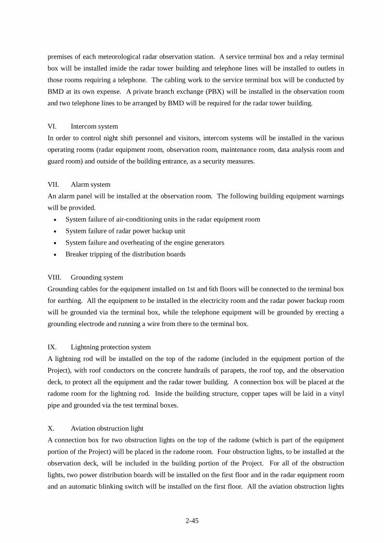
2-45
premises of each meteorological radar observation station. A service terminal box and a relay terminal box will be installed inside the radar tower building and telephone lines will be installed to outlets in those rooms requiring a telephone. The cabling work to the service terminal box will be conducted by BMD at its own expense. A private branch exchange (PBX) will be installed in the observation room and two telephone lines to be arranged by BMD will be required for the radar tower building. VI. Intercom system In order to control night shift personnel and visitors, intercom systems will be installed in the various operating rooms (radar equipment room, observation room, maintenance room, data analysis room and guard room) and outside of the building entrance, as a security measures.
VII. Alarm system An alarm panel will be installed at the observation room. The following building equipment warnings will be provided. • System failure of air-conditioning units in the radar equipment room • System failure of radar power backup unit • System failure and overheating of the engine generators • Breaker tripping of the distribution boards
VIII. Grounding system Grounding cables for the equipment installed on 1st and 6th floors will be connected to the terminal box for earthing. All the equipment to be installed in the electricity room and the radar power backup room will be grounded via the terminal box, while the telephone equipment will be grounded by erecting a grounding electrode and running a wire from there to the terminal box.
IX. Lightning protection system A lightning rod will be installed on the top of the radome (included in the equipment portion of the Project), with roof conductors on the concrete handrails of parapets, the roof top, and the observation deck, to protect all the equipment and the radar tower building. A connection box will be placed at the radome room for the lightning rod. Inside the building structure, copper tapes will be laid in a vinyl pipe and grounded via the test terminal boxes.
X. Aviation obstruction light A connection box for two obstruction lights on the top of the radome (which is part of the equipment portion of the Project) will be placed in the radome room. Four obstruction lights, to be installed at the observation deck, will be included in the building portion of the Project. For all of the obstruction lights, two power distribution boards will be installed on the first floor and in the radar equipment room and an automatic blinking switch will be installed on the first floor. All the aviation obstruction lights

2-46
will be furnished with surge arresters. Connecting work between the obstruction lights on the top of radome and a connection box placed in the radome will be included in the equipment portion of the Project.
XI. Fire detection and alarm system Fire detectors will be installed in the radar equipment room, the electricity room, the radar power backup room and the engine generator room, and an alarm system will be installed in the observation room.
[8] Water Supply, Drainage and Sanitary Fixture Design
I. Water supply system The public water supply pipe has been laid along the frontal road on the north side of the project site in Moulvibazar. For the water intake for the radar tower building, a water supply gate valve will be installed. BMD will be responsible for connecting the plumbing to a gate valve.
II. Drainage system Drainage will be divided into 2 systems - sewage and miscellaneous drainage. Sewage will primarily be treated in a septic tank and then be permeated by a seepage pit into the ground. Miscellaneous drainage will be fed directly into a seepage pit. A septic tank and a seepage pit must be constructed. The capacity of the septic tank and seepage pit for the radar tower building has been designed for 12 BMD personnel in the operations area and for some visitors.
III. Sanitary fixtures • Closet bowl: Bangladesh local style and European style individually • Washbasin: wall-mounted type • Slop sink: wall-mounted type
IV. Fire extinguisher Fire extinguishers will be supplied in the following rooms.
Radome Room: CO2 type Engine Generator Room: ABC type
Radar Equipment Room: CO2 type Electricity Room: CO2 type
Observation Room: CO2 type Pump Room: CO2 type
Data Analysis Room: CO2 type Radar Power Backup Room: CO2 type
Data Storage Room: CO2 type Tea Kitchen: ABC type
Maintenance Room: CO2 type

2-47
[9] Air-conditioning and Ventilation System Design
Air-conditioning systems will be installed in the rooms listed below. It is essential to have a good operating environment, especially for the equipment in the radar equipment room and the observation room; therefore the plural number of air-conditioning systems is indispensable. Package type air-conditioning systems have been selected to minimize any impact to the operation of the radar system if an air-conditioning system fails. • Radar Equipment Room • Observation Room • Data Analysis Room • Data Storage Room • Maintenance Room
Ceiling fan forced ventilation will be installed in the tea kitchen and the toilets. Due to the heat generated by the equipment in the radar equipment room, the engine generator room, the radar power backup room, the electricity room, pump room, etc., forced ventilation systems will be adopted. Furthermore, appropriate ventilation systems will be installed in other rooms to meet the following conditions.
<Environmental conditions>
• Outside condition: 35°C (maximum temperature) • Indoor condition: temperature 26°C humidity 40-60%
In the radar equipment room: temperature 25°C humidity 40-60%

2-48
The following diagrams of the building equipment plan for the radar tower building are attached from the next page. <Moulvibazar Meteorological Radar Tower Building>
• Power Feeder Diagram System Diagram 1 (SD-01) • Power Riser System System Diagram 2 (SD -02) • Interphone System & Tel Diagram System Diagram 3 (SD -03) • Riser Fire Alarm System System Diagram 4 (SD -04) • Alarm System Diagram System Diagram 5 (SD -05) • Riser Diagram Lightning Protection & Grounding System System Diagram 6 (SD -06) • Riser Diagram Obstruction Lighting System Diagram 7 (SD -07) • Water Supply & Drainage System System Diagram 8 (SD -08) • Air-Conditioning & Ventilation System Diagram System Diagram 9 (SD -09)
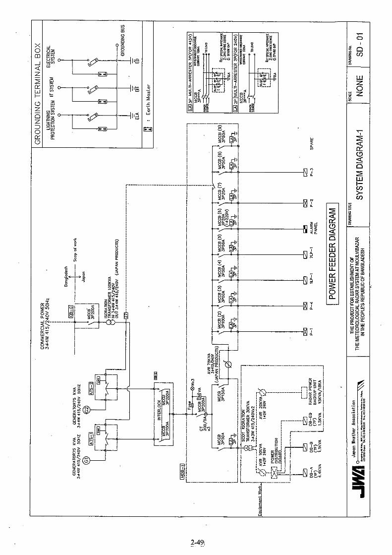
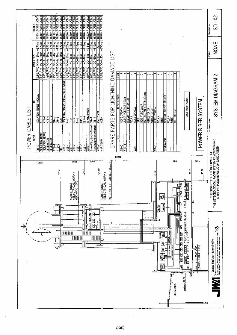
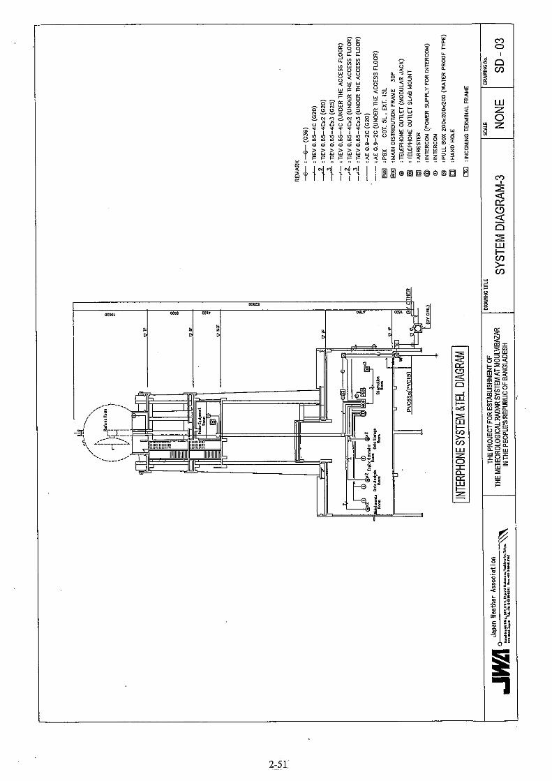
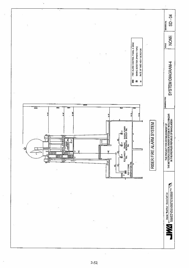
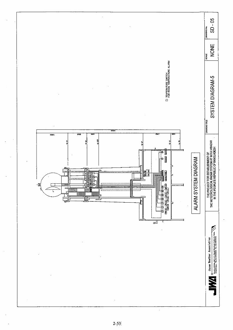
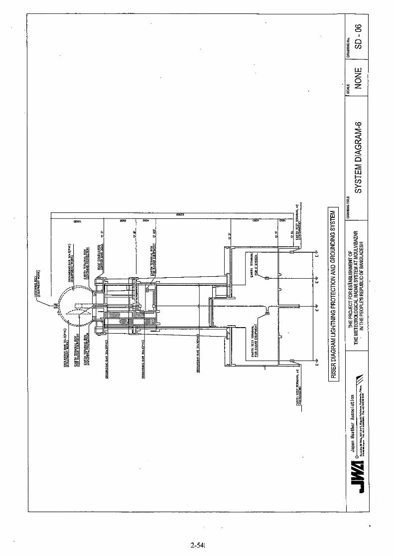
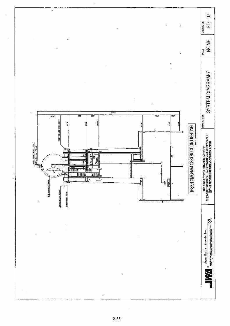
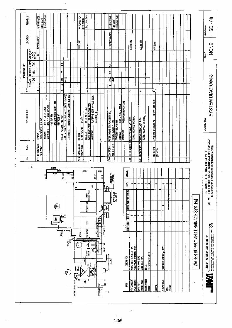
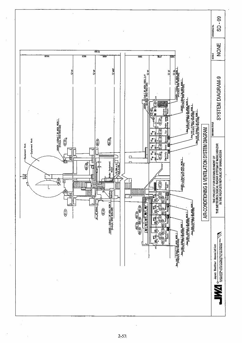


![BASIC EDUCATION SECTOR ANALYSIS REPORT - RWANDA …open_jicareport.jica.go.jp/pdf/12083317.pdf · basic education sector analysis report ... [learning outcomes] ... basic education](https://img.pdfslide.us/doc/110x75/5acfb6dc7f8b9a8b1e8d08b3/basic-education-sector-analysis-report-rwanda-open-education-sector-analysis.jpg)