Embed Size (px)
Citation preview

User Manual
Basic ConfigurationRail Switch Power Smart (RSPS)
UM BasicConfig RSPSRelease 2.0 02/2013
Technical Supporthttps://hirschmann-support.belden.eu.com

The naming of copyrighted trademarks in this manual, even when not specially indicated, should not be taken to mean that these names may be considered as free in the sense of the trademark and tradename protection law and hence that they may be freely used by anyone.
© 2013 Hirschmann Automation and Control GmbH
Manuals and software are protected by copyright. All rights reserved. The copying, reproduction, translation, conversion into any electronic medium or machine scannable form is not permitted, either in whole or in part. An exception is the preparation of a backup copy of the software for your own use. For devices with embedded software, the end-user license agreement on the enclosed CD/DVD applies.
The performance features described here are binding only if they have been expressly agreed when the contract was made. This document was produced by Hirschmann Automation and Control GmbH according to the best of the company's knowledge. Hirschmann reserves the right to change the contents of this document without prior notice. Hirschmann can give no guarantee in respect of the correctness or accuracy of the information in this document.
Hirschmann can accept no responsibility for damages, resulting from the use of the network components or the associated operating software. In addition, we refer to the conditions of use specified in the license contract.
You can get the latest version of this manual on the Internet at the Hirschmann product site (www.hirschmann.com).
Printed in GermanyHirschmann Automation and Control GmbHStuttgarter Str. 45-5172654 NeckartenzlingenGermanyTel.: +49 1805 141538
Rel. 2.0 - 02/2013 – 21.02.2013
Contents
Contents
About this Manual 9
Key 11
Introduction 13
1 User interfaces 15
1.1 Graphical user interface (GUI) 161.1.1 HiView 161.1.2 Web browser 17
1.2 Command Line Interface 191.2.1 Preparing the connection 191.2.2 CLI access via telnet 201.2.3 CLI via SSH (Secure Shell) 251.2.4 CLI via the V.24 port 29
1.3 System Monitor 331.3.1 Functional scope 331.3.2 Starting the System Monitor 33
2 Entering IP Parameters 35
2.1 IP Parameter Basics 362.1.1 IP Address (Version 4) 362.1.2 Netmask 372.1.3 Classless Inter-Domain Routing 40
2.2 Entering IP parameters via CLI 42
2.3 Entering the IP Parameters via HiDiscovery 45
2.4 Enter the IP Parameter using the web-based interface 47
2.5 Entering IP Parameters per BOOTP 49
2.6 Entering IP Parameters per DHCP 50
2.7 Management Address Conflict Detection 532.7.1 Active and Passive detection 53
UM BasicConfig RSPSRelease 2.0 02/2013 3
Contents
3 Access to the device 55
3.1 Authentication lists 563.1.1 Applications 563.1.2 Methods 563.1.3 Default setting 573.1.4 Managing authentication lists 583.1.5 Adjusting the settings 59
3.2 User Management 663.2.1 Privilege Levels 663.2.2 Managing user accounts 683.2.3 Default setting 703.2.4 Changing standard passwords 703.2.5 Setting up a new user account 733.2.6 Deactivating the user account 763.2.7 Adjusting policies for passwords 77
3.3 SNMP Access 803.3.1 SNMPv1/v2 Community 803.3.2 SNMPv3 access 84
4 Managing configuration profiles 87
4.1 Detecting changed settings 88
4.2 Saving settings 904.2.1 Saving the configuration profile in the device 904.2.2 Saving the configuration profile in external memory 964.2.3 Exporting a configuration profile 98
4.3 Loading settings 1004.3.1 Activating a configuration profile 1004.3.2 Loading the configuration profile from the external
memory 1034.3.3 Importing a configuration profile 106
4.4 Resetting the device to the factory defaults 1094.4.1 With the graphical user interface or CLI 1094.4.2 In the System Monitor 111
4UM BasicConfig RSPS
Release 2.0 02/2013
Contents
5 Synchronizing the System Time in the Network 113
5.1 Basic settings 1145.1.1 Setting the time 1145.1.2 Automatic daylight saving time changeover 116
5.2 SNTP 1185.2.1 Preparation 1205.2.2 Defining settings of the SNTP client 1215.2.3 Specifying SNTP server settings 124
5.3 PTP 1265.3.1 Types of clocks 1265.3.2 Best Master Clock algorithm 1285.3.3 Delay measurement 1295.3.4 PTP domains 1305.3.5 Using PTP 131
6 Network Load Control 133
6.1 Direct Packet Distribution 1346.1.1 Learning MAC addresses 1356.1.2 Aging of learned MAC addresses 1356.1.3 Static address entries 136
6.2 Multicasts 1416.2.1 Example of a Multicast Application 1416.2.2 IGMP snooping 142
6.3 Rate limiter 150
6.4 QoS/Priority 1526.4.1 Description of Prioritization 1536.4.2 Handling of Received Priority Information 1546.4.3 VLAN tagging 1556.4.4 IP ToS / DiffServ 1576.4.5 Handling of traffic classes 1596.4.6 Management prioritization 1606.4.7 Setting prioritization 161
6.5 Flow Control 1676.5.1 Halfduplex or fullduplex link. 1686.5.2 Setting the Flow Control 169
UM BasicConfig RSPSRelease 2.0 02/2013 5
Contents
7 VLANs 171
7.1 Examples of VLANs 1727.1.1 Example 1 1727.1.2 Example 2 178
7.2 Creating a Voice VLAN 185
7.3 VLAN unaware mode 186
8 Operation Diagnosis 187
8.1 Sending Traps 1888.1.1 List of SNMP traps 1898.1.2 Traps for configuration activity 1908.1.3 Configuring Traps 1918.1.4 ICMP Messaging 192
8.2 Monitoring the Device Status 1938.2.1 Events which can be monitored 1948.2.2 Configuring the Device Status 1948.2.3 Displaying the Device Status 196
8.3 Security Status (DEVMON) 1978.3.1 Events which can be monitored 1988.3.2 Configuring the Security Status 1998.3.3 Displaying the Security Status 200
8.4 Out-of-band Signalling 2018.4.1 Controlling the Signal Contact 2028.4.2 Monitoring the Device Status via the Signal Contact 203
8.5 Port Status Indication 205
8.6 Event Counter at Port Level 2068.6.1 Detecting Non-matching Duplex Modes 207
8.7 Displaying the SFP Status 209
8.8 Topology Discovery 2108.8.1 Displaying the Topology Discovery Results 2118.8.2 LLDP-Med 212
8.9 Detecting Loops 213
8.10 Reports 2148.10.1 Global Settings 2158.10.2 Syslog 2178.10.3 System Log 2188.10.4 Audit Trail 219
6UM BasicConfig RSPS
Release 2.0 02/2013
Contents
8.11 Network Analysis with TCPDump 220
8.12 Monitoring Data Traffic on the Ports (Port Mirroring) 221
8.13 Cause and Action management during Selftest 223
9 Advanced functions of the device 225
9.1 Telnet Client 226
A Setting up the Configuration Environment 227
A.1 Setting up a DHCP/BOOTP Server 228
B General Information 235
B.1 Management Information Base (MIB) 236
B.2 Abbreviations used 239
B.3 Technical Data 240
B.4 Maintenance 241
B.5 Readers’ Comments 242
C Index 245
D Further Support 247
UM BasicConfig RSPSRelease 2.0 02/2013 7

Contents
8UM BasicConfig RSPS
Release 2.0 02/2013
About this Manual
About this Manual
The “Basic Configuration” user manual contains the information you need to start operating the device. It takes you step by step from the first startup operation through to the basic settings for operation in your environment.
The “Installation” user manual contains a device description, safety instructions, a description of the display, and the other information that you need to install the device.
The “GUI” reference manual contains detailed information on using the graphical interface to operate the individual functions of the device.
The “Command Line Interface” reference manual contains detailed information on using the Command Line Interface to operate the individual functions of the device.
The “Redundancy Configuration” user manual document contains the information you require to select the suitable redundancy procedure and configure it.
The “HiView” user manual contains information for using the HiView GUI application. This application allows you to use the graphical user interface of Hirschmann devices with management independently of other applications, such as a browser.
UM BasicConfig RSPSRelease 2.0 02/2013 9
About this Manual
The Industrial HiVision Network Management Software provides you with additional options for smooth configuration and monitoring:
Simultaneous configuration of multiple devices Graphical user interface with network layout Auto-topology discovery Event log Event handling Client/server structure Browser interface ActiveX control for SCADA integration SNMP/OPC gateway.
10UM BasicConfig RSPS
Release 2.0 02/2013
Key
Key
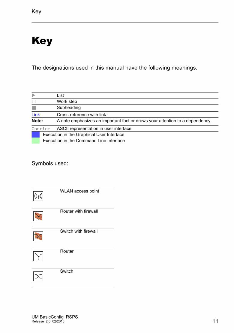
The designations used in this manual have the following meanings:
Symbols used:
List Work step
Subheading
Link Cross-reference with linkNote: A note emphasizes an important fact or draws your attention to a dependency.
Courier ASCII representation in user interfaceExecution in the Graphical User InterfaceExecution in the Command Line Interface
WLAN access point
Router with firewall
Switch with firewall
Router
Switch
UM BasicConfig RSPSRelease 2.0 02/2013 11
Key
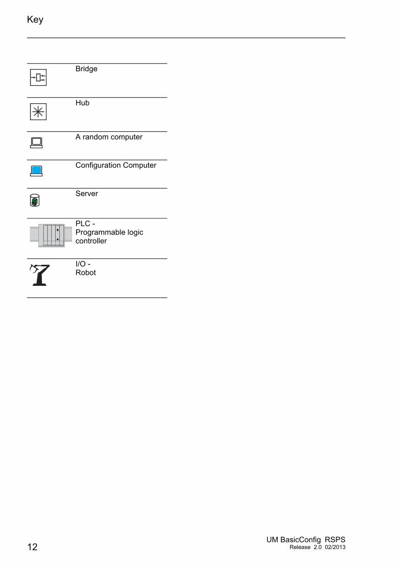
Bridge
Hub
A random computer
Configuration Computer
Server
PLC -Programmable logic controller
I/O -Robot
12UM BasicConfig RSPS
Release 2.0 02/2013
Introduction
Introduction
The device has been developed for use in a harsh industrial environment. Accordingly, the installation process has been kept simple. Thanks to the selected default settings, you only have to enter a few settings before starting to operate the device.
Note: The changes you make in the dialogs are copied into the volatile memory of the device when you click on "Set".To save the changes to the device into permanent memory, select the saving location in the Basic Settings:Load/Save dialog box and click on "Save".
UM BasicConfig RSPSRelease 2.0 02/2013 13

Introduction
14UM BasicConfig RSPS
Release 2.0 02/2013
User interfaces
1 User interfaces
The device allows you to specify the settings of the device using the following user interfaces.
User interface Can be reached through …
Prerequisite
Graphical user interface (GUI) Ethernet (in-band) HiView orWeb browser and Java
Command Line Interface (CLI) Ethernet (in-band)V.24 (out-of-band)
Terminal emulation software
System Monitor V.24 (out-of-band) Terminal emulation software
Table 1: User interfaces for accessing the management of the device
UM BasicConfig RSPSRelease 2.0 02/2013 15
User interfaces 1.1 Graphical user interface (GUI)
1.1 Graphical user interface (GUI)
The graphical user Interface (GUI) allows you to conveniently define and monitor the settings of the device from a computer on the network.
You reach the graphical user interface (GUI) with the following programs: HiView Web browser
1.1.1 HiView
HiView is a stand-alone application. HiView thus allows you to use the graphical user interface of Hirschmann Ethernet devices with management independently of other applications, such as a browser.The portability of HiView enables you to store HiView on a portable storage medium and start it on other computers in your data network.
You will find a detailed description of the HiView GUI application in the „HiView“ user manual.
16UM BasicConfig RSPS
Release 2.0 02/2013
User interfaces 1.1 Graphical user interface (GUI)
1.1.2 Web browser
System requirementsTo open the graphical user interface, you need a Web browser, for example Mozilla Firefox version 3.5 or later, or Microsoft Internet Explorer version 6 or later.
Installation
Note: The graphical user interface uses Java 6 or Java 7.
Install the software from the enclosed CD-ROM. To do this, you go to “Additional Software”, select Java Runtime Environment and click on “Installation”.
UM BasicConfig RSPSRelease 2.0 02/2013 17
User interfaces 1.1 Graphical user interface (GUI)
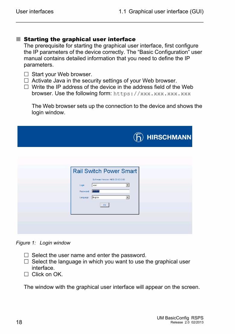
Starting the graphical user interfaceThe prerequisite for starting the graphical user interface, first configure the IP parameters of the device correctly. The “Basic Configuration” user manual contains detailed information that you need to define the IP parameters.
Start your Web browser. Activate Java in the security settings of your Web browser. Write the IP address of the device in the address field of the Web
browser. Use the following form: https://xxx.xxx.xxx.xxx
The Web browser sets up the connection to the device and shows the login window.
Figure 1: Login window
Select the user name and enter the password. Select the language in which you want to use the graphical user
interface. Click on OK.
The window with the graphical user interface will appear on the screen.
18UM BasicConfig RSPS
Release 2.0 02/2013
User interfaces 1.2 Command Line Interface
1.2 Command Line Interface
The Command Line Interface enables you to use the functions of the device through a local or remote connection.
The Command Line Interface provides IT specialists with a familiar environment for configuring IT devices. As an experienced user or administrator, you have knowledge about the basics and about using Rail Switch Power Smart devices.
The “Command Line Interface” reference manual gives you step-by-step information on using the Command Line Interface (CLI) and its commands.
1.2.1 Preparing the connection
Information for assembling and starting up your RSPS device can be found in the “Installation” user manual.
UM BasicConfig RSPSRelease 2.0 02/2013 19
User interfaces 1.2 Command Line Interface
You will find information for configuring your RSPS device in the “Configuration” user manual
Connect your Switch with the network. The network parameters must be set correctly for the connection to be successful.
You can access the user interface of the Command Line Interface with the freeware program PuTTY.
Install PuTTY on your computer.
1.2.2 CLI access via telnet
Telnet connection via Windows
Note: Telnet is only installed as standard in Windows versions before Windows Vista.
Start screen
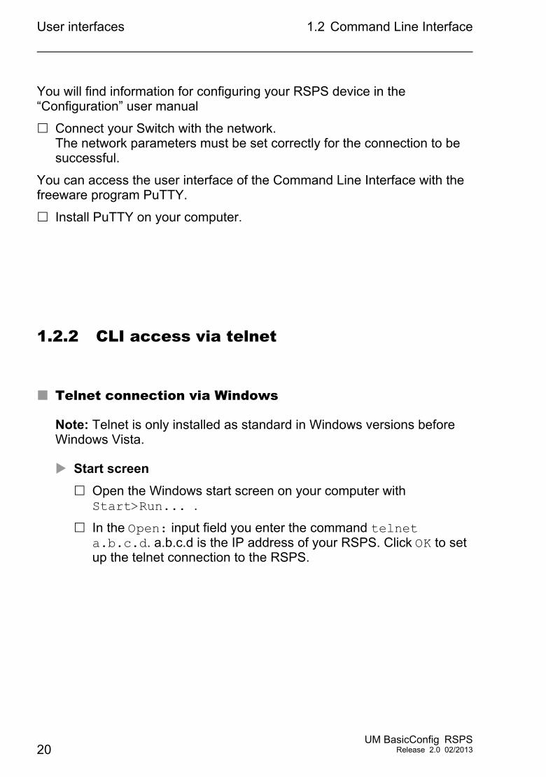
Open the Windows start screen on your computer with Start>Run... .
In the Open: input field you enter the command telnet a.b.c.d. a.b.c.d is the IP address of your RSPS. Click OK to set up the telnet connection to the RSPS.
20UM BasicConfig RSPS
Release 2.0 02/2013
User interfaces 1.2 Command Line Interface
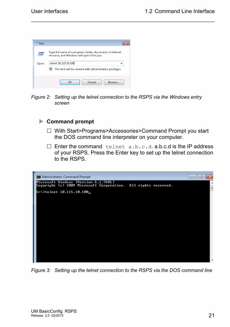
Figure 2: Setting up the telnet connection to the RSPS via the Windows entry screen
Command prompt
With Start>Programs>Accessories>Command Prompt you start the DOS command line interpreter on your computer.
Enter the command telnet a.b.c.d. a.b.c.d is the IP address of your RSPS. Press the Enter key to set up the telnet connection to the RSPS.
Figure 3: Setting up the telnet connection to the RSPS via the DOS command line
UM BasicConfig RSPSRelease 2.0 02/2013 21
User interfaces 1.2 Command Line Interface
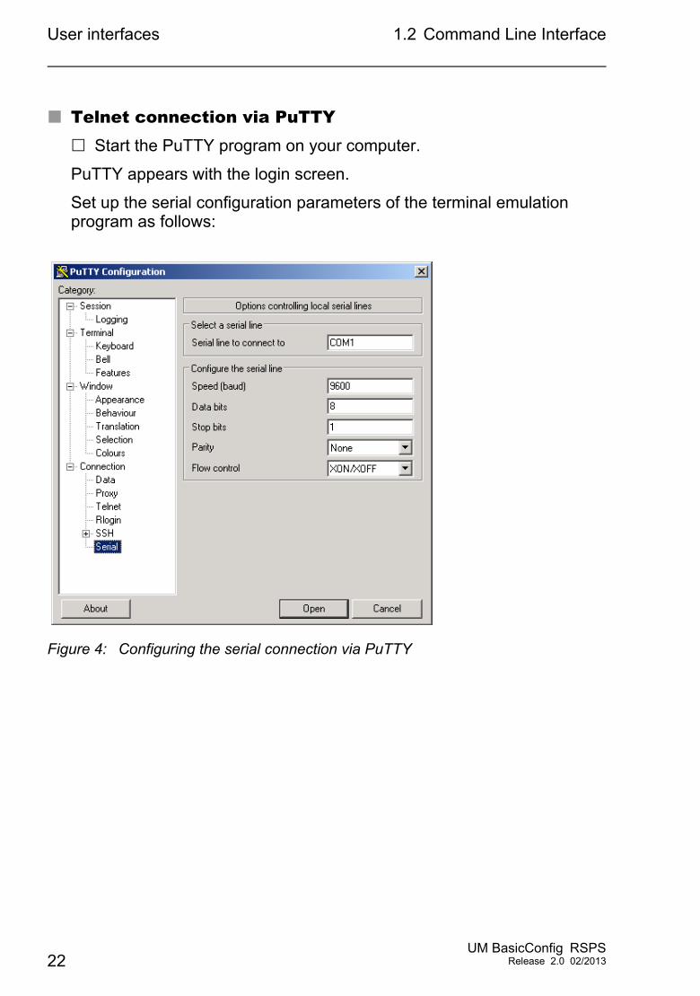
Telnet connection via PuTTY Start the PuTTY program on your computer.
PuTTY appears with the login screen.
Set up the serial configuration parameters of the terminal emulation program as follows:
Figure 4: Configuring the serial connection via PuTTY
22UM BasicConfig RSPS
Release 2.0 02/2013
User interfaces 1.2 Command Line Interface
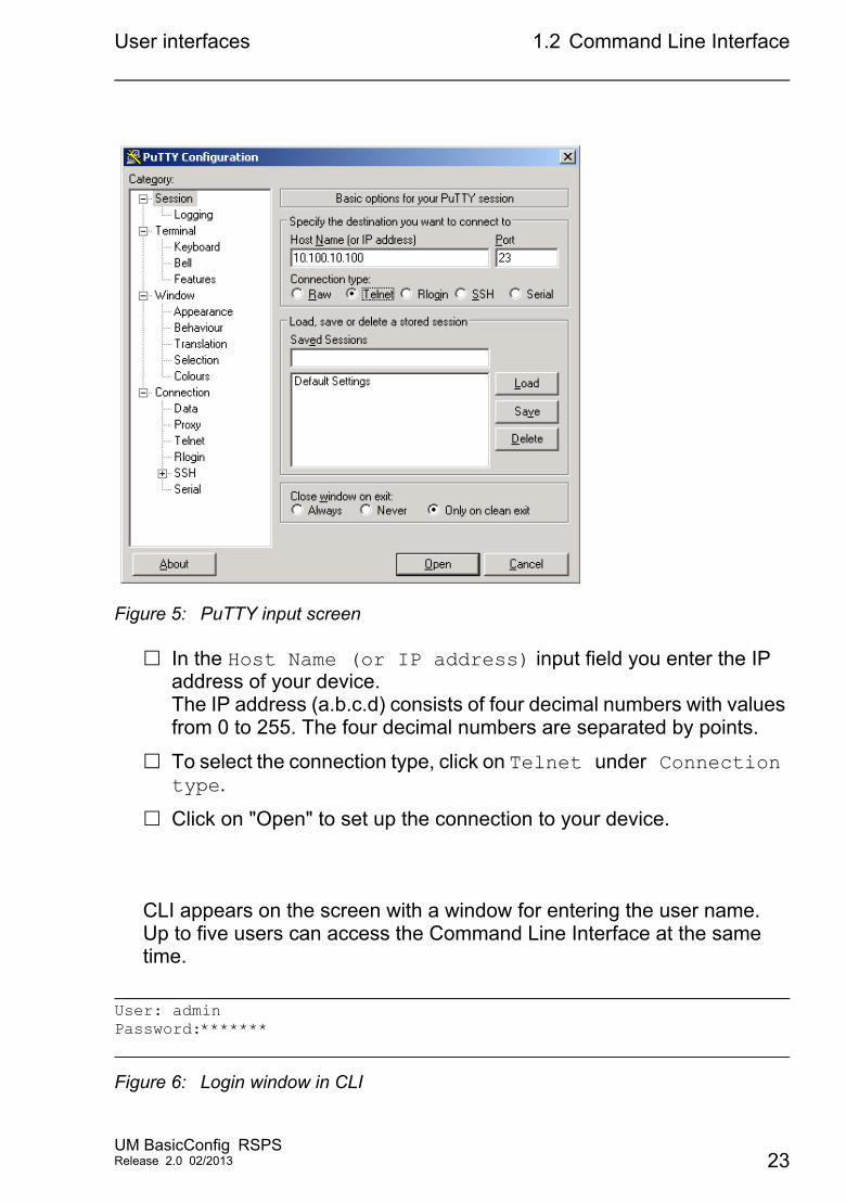
Figure 5: PuTTY input screen
In the Host Name (or IP address) input field you enter the IP address of your device.The IP address (a.b.c.d) consists of four decimal numbers with values from 0 to 255. The four decimal numbers are separated by points.
To select the connection type, click on Telnet under Connection type.
Click on "Open" to set up the connection to your device.
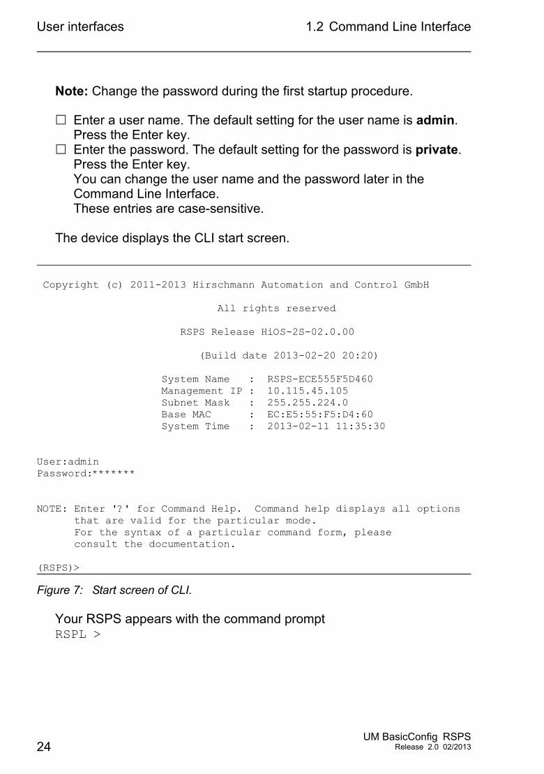
CLI appears on the screen with a window for entering the user name. Up to five users can access the Command Line Interface at the same time.
Figure 6: Login window in CLI
User: adminPassword:*******
UM BasicConfig RSPSRelease 2.0 02/2013 23
User interfaces 1.2 Command Line Interface
Note: Change the password during the first startup procedure.
Enter a user name. The default setting for the user name is admin. Press the Enter key.
Enter the password. The default setting for the password is private. Press the Enter key.You can change the user name and the password later in the Command Line Interface.These entries are case-sensitive.
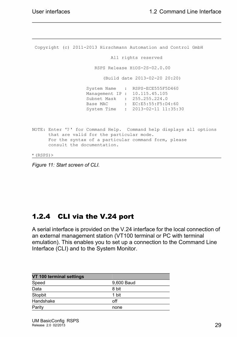
The device displays the CLI start screen.
Figure 7: Start screen of CLI.
Your RSPS appears with the command prompt RSPL >
Copyright (c) 2011-2013 Hirschmann Automation and Control GmbH
All rights reserved
RSPS Release HiOS-2S-02.0.00
(Build date 2013-02-20 20:20)
System Name : RSPS-ECE555F5D460 Management IP : 10.115.45.105 Subnet Mask : 255.255.224.0 Base MAC : EC:E5:55:F5:D4:60 System Time : 2013-02-11 11:35:30
User:adminPassword:*******
NOTE: Enter '?' for Command Help. Command help displays all options that are valid for the particular mode. For the syntax of a particular command form, please consult the documentation.
(RSPS)>
24UM BasicConfig RSPS
Release 2.0 02/2013

User interfaces 1.2 Command Line Interface
1.2.3 CLI via SSH (Secure Shell)
Start the PuTTY program on your computer.
PuTTY appears with the login screen.
UM BasicConfig RSPSRelease 2.0 02/2013 25
User interfaces 1.2 Command Line Interface
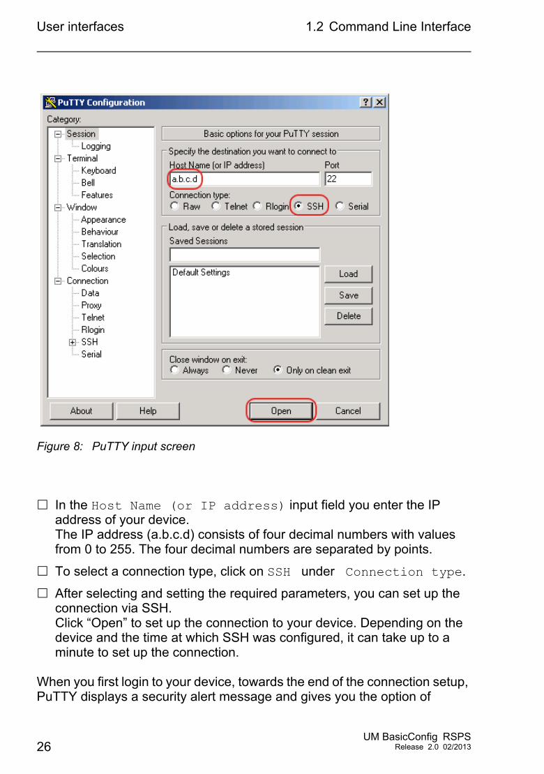
Figure 8: PuTTY input screen
In the Host Name (or IP address) input field you enter the IP address of your device.The IP address (a.b.c.d) consists of four decimal numbers with values from 0 to 255. The four decimal numbers are separated by points.
To select a connection type, click on SSH under Connection type.
After selecting and setting the required parameters, you can set up the connection via SSH. Click “Open” to set up the connection to your device. Depending on the device and the time at which SSH was configured, it can take up to a minute to set up the connection.
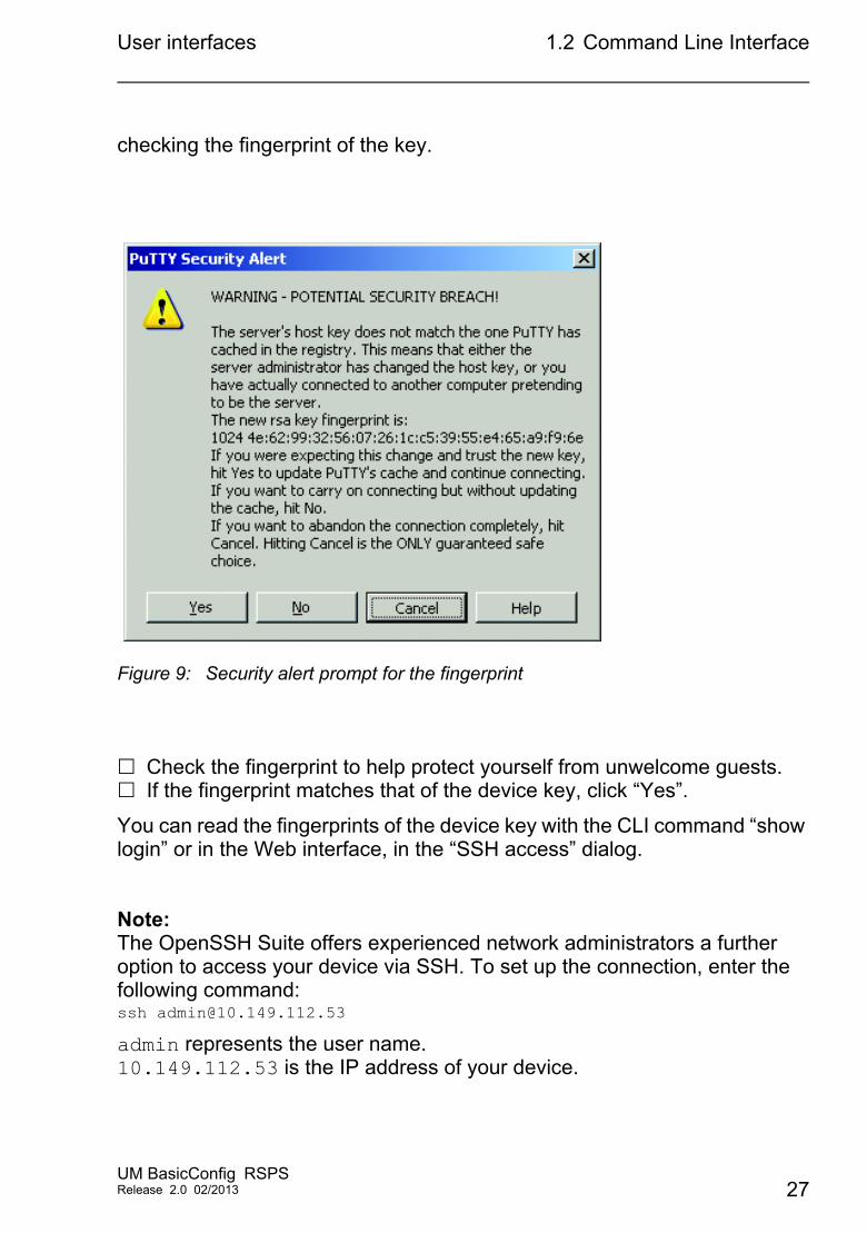
When you first login to your device, towards the end of the connection setup, PuTTY displays a security alert message and gives you the option of
26UM BasicConfig RSPS
Release 2.0 02/2013
User interfaces 1.2 Command Line Interface
checking the fingerprint of the key.
Figure 9: Security alert prompt for the fingerprint
Check the fingerprint to help protect yourself from unwelcome guests. If the fingerprint matches that of the device key, click “Yes”.
You can read the fingerprints of the device key with the CLI command “show login” or in the Web interface, in the “SSH access” dialog.
Note:The OpenSSH Suite offers experienced network administrators a further option to access your device via SSH. To set up the connection, enter the following command: ssh [email protected]
admin represents the user name.10.149.112.53 is the IP address of your device.
UM BasicConfig RSPSRelease 2.0 02/2013 27
User interfaces 1.2 Command Line Interface
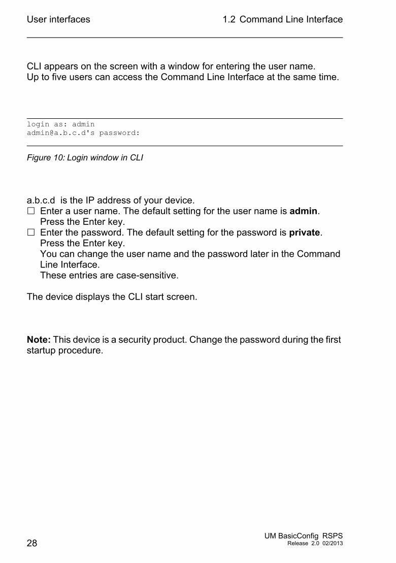
CLI appears on the screen with a window for entering the user name. Up to five users can access the Command Line Interface at the same time.
Figure 10: Login window in CLI
a.b.c.d is the IP address of your device. Enter a user name. The default setting for the user name is admin.
Press the Enter key. Enter the password. The default setting for the password is private.
Press the Enter key.You can change the user name and the password later in the Command Line Interface.These entries are case-sensitive.
The device displays the CLI start screen.
Note: This device is a security product. Change the password during the first startup procedure.
login as: [email protected]'s password:
28UM BasicConfig RSPS
Release 2.0 02/2013
User interfaces 1.2 Command Line Interface
Figure 11: Start screen of CLI.
1.2.4 CLI via the V.24 port
A serial interface is provided on the V.24 interface for the local connection of an external management station (VT100 terminal or PC with terminal emulation). This enables you to set up a connection to the Command Line Interface (CLI) and to the System Monitor.
Copyright (c) 2011-2013 Hirschmann Automation and Control GmbH
All rights reserved
RSPS Release HiOS-2S-02.0.00
(Build date 2013-02-20 20:20)
System Name : RSPS-ECE555F5D460 Management IP : 10.115.45.105 Subnet Mask : 255.255.224.0 Base MAC : EC:E5:55:F5:D4:60 System Time : 2013-02-11 11:35:30
NOTE: Enter '?' for Command Help. Command help displays all options that are valid for the particular mode. For the syntax of a particular command form, please consult the documentation.
*(RSPS)>
VT 100 terminal settingsSpeed 9,600 BaudData 8 bitStopbit 1 bitHandshake offParity none
UM BasicConfig RSPSRelease 2.0 02/2013 29
User interfaces 1.2 Command Line Interface
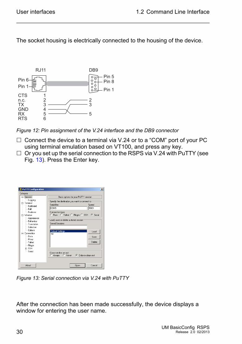
The socket housing is electrically connected to the housing of the device.
Figure 12: Pin assignment of the V.24 interface and the DB9 connector
Connect the device to a terminal via V.24 or to a “COM” port of your PC using terminal emulation based on VT100, and press any key.
Or you set up the serial connection to the RSPS via V.24 with PuTTY (see Fig. 13). Press the Enter key.
Figure 13: Serial connection via V.24 with PuTTY
After the connection has been made successfully, the device displays a window for entering the user name.
Pin 1Pin 1
Pin 8Pin 5
Pin 6
RJ11 DB9
23
5
123456
CTSn.c.TXGNDRXRTS
30UM BasicConfig RSPS
Release 2.0 02/2013
User interfaces 1.2 Command Line Interface
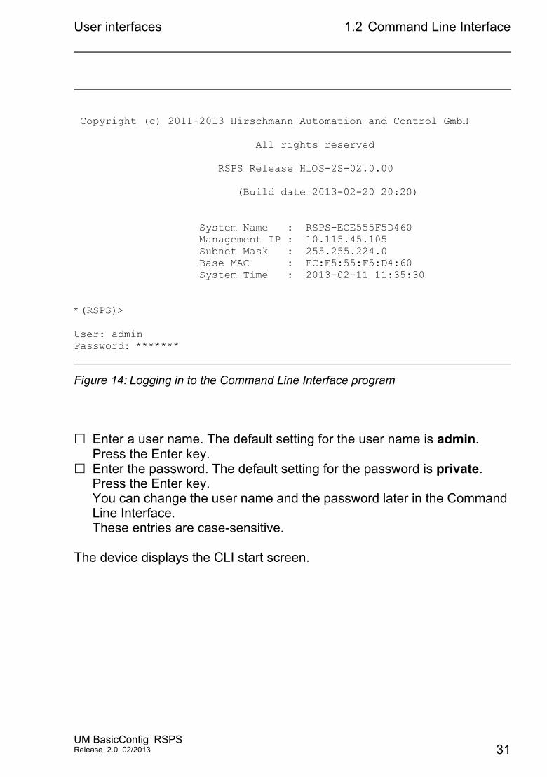
Figure 14: Logging in to the Command Line Interface program
Enter a user name. The default setting for the user name is admin. Press the Enter key.
Enter the password. The default setting for the password is private. Press the Enter key.You can change the user name and the password later in the Command Line Interface.These entries are case-sensitive.
The device displays the CLI start screen.
Copyright (c) 2011-2013 Hirschmann Automation and Control GmbH
All rights reserved
RSPS Release HiOS-2S-02.0.00
(Build date 2013-02-20 20:20)
System Name : RSPS-ECE555F5D460 Management IP : 10.115.45.105 Subnet Mask : 255.255.224.0 Base MAC : EC:E5:55:F5:D4:60 System Time : 2013-02-11 11:35:30
*(RSPS)>
User: adminPassword: *******
UM BasicConfig RSPSRelease 2.0 02/2013 31
User interfaces 1.2 Command Line Interface
Figure 15: CLI screen after login
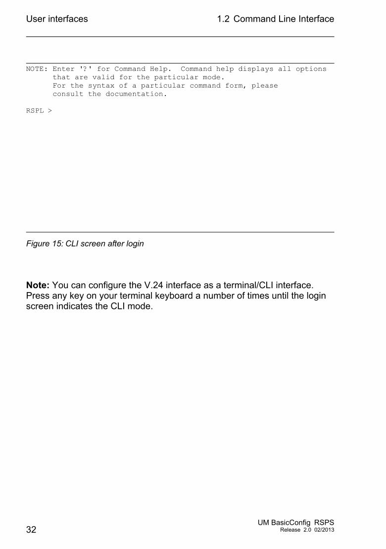
Note: You can configure the V.24 interface as a terminal/CLI interface.Press any key on your terminal keyboard a number of times until the login screen indicates the CLI mode.
NOTE: Enter '?' for Command Help. Command help displays all options that are valid for the particular mode. For the syntax of a particular command form, please consult the documentation.
RSPL >
32UM BasicConfig RSPS
Release 2.0 02/2013
User interfaces 1.3 System Monitor
1.3 System Monitor
The System Monitor allows you to set basic operating parameters before starting the operating system.
1.3.1 Functional scope
In the System Monitor, you carry out the following tasks, for example: Updating the operating system Starting the operating system Deleting configuration profiles, resetting the device to the factory defaults Checking boot code information
1.3.2 Starting the System Monitor
Prerequisites Terminal cable for connecting the device to your PC (available as an
optional accessory). PC with VT100 terminal emulation (such as PuTTY) or serial terminal
Perform the following work steps:
Use the terminal cable to connect the V.24 port of the device with the “COM” port of the PC.
Start the VT100 terminal emulation on the PC. Define the following transmission parameters:
– Speed: 9600 Baud– Data: 8 bit– Parity: None
UM BasicConfig RSPSRelease 2.0 02/2013 33
User interfaces 1.3 System Monitor
– Stopbit: 1 bit– Flow control: None
Set up a connection to the device. Switch on the device. If the device is already on, reboot it.
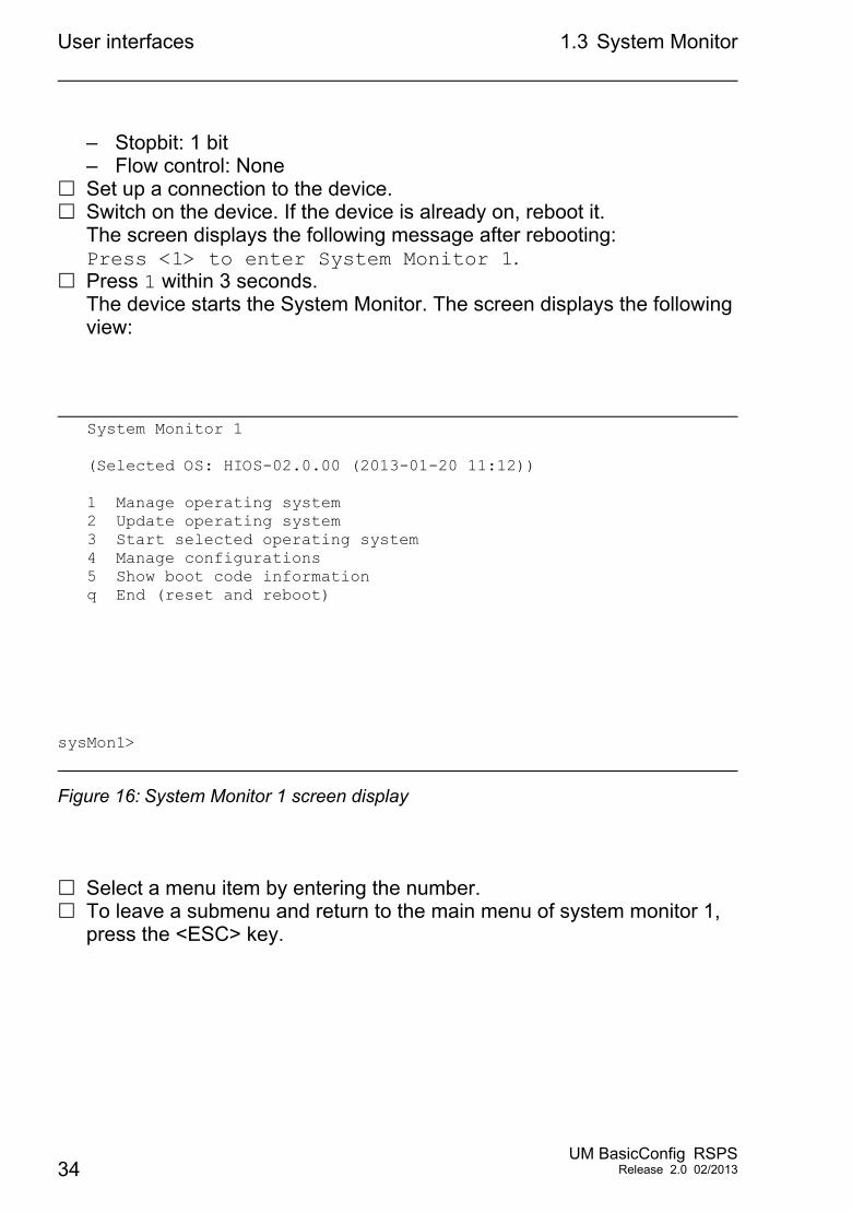
The screen displays the following message after rebooting:Press <1> to enter System Monitor 1.
Press 1 within 3 seconds.The device starts the System Monitor. The screen displays the following view:
Figure 16: System Monitor 1 screen display
Select a menu item by entering the number. To leave a submenu and return to the main menu of system monitor 1,
press the <ESC> key.
System Monitor 1
(Selected OS: HIOS-02.0.00 (2013-01-20 11:12))
1 Manage operating system 2 Update operating system 3 Start selected operating system 4 Manage configurations 5 Show boot code information q End (reset and reboot)
sysMon1>
34UM BasicConfig RSPS
Release 2.0 02/2013
Entering IP Parameters
2 Entering IP Parameters
When you install the device for the first time enter the IP parameters.
The device provides the following options for entering the IP parameters during the first installation:
Entry using the Command Line Interface (CLI).You choose this “out of band” method if you preconfigure your device outside its operating environment, or you restore network access (“in-band”) to the device
Entry using the HiDiscovery protocol.You choose this “in-band” method on a previously installed network device or if you have another Ethernet connection between your PC and the device
Configuration using the external memory.You choose this method if you are replacing a device with a device of the same type and have already saved the configuration in the external memory.
Using BOOTP.You choose this “in-band” method to configure the installed device using BOOTP. You need a BOOTP server for this method. The BOOTP server assigns the configuration data to the device using its MAC address. The DHCP mode is the default mode for the configuration data reference, set the parameter to the BOOTP mode for this method.
Configuration via DHCP.You choose this “in-band” method to configure the installed device using DHCP. You need a DHCP server for this method. The DHCP server assigns the configuration data to the device using its MAC address or its system name.
Configuration via the web-based interface.If the device already has an IP address and is reachable via the network, then the web-based interface provides you with another option for configuring the IP parameters.
UM BasicConfig RSPSRelease 2.0 02/2013 35
Entering IP Parameters 2.1 IP Parameter Basics
2.1 IP Parameter Basics
2.1.1 IP Address (Version 4)
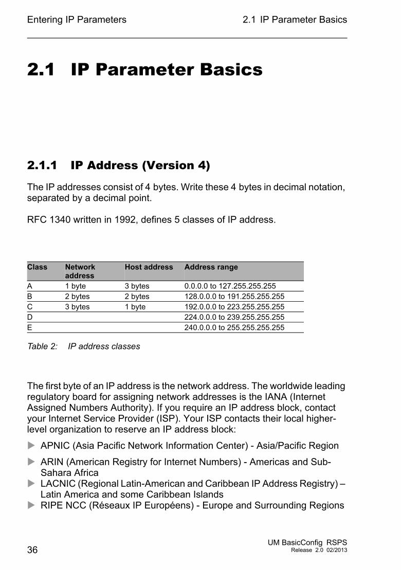
The IP addresses consist of 4 bytes. Write these 4 bytes in decimal notation, separated by a decimal point.
RFC 1340 written in 1992, defines 5 classes of IP address.
The first byte of an IP address is the network address. The worldwide leading regulatory board for assigning network addresses is the IANA (Internet Assigned Numbers Authority). If you require an IP address block, contact your Internet Service Provider (ISP). Your ISP contacts their local higher-level organization to reserve an IP address block:
APNIC (Asia Pacific Network Information Center) - Asia/Pacific Region
ARIN (American Registry for Internet Numbers) - Americas and Sub-Sahara Africa
LACNIC (Regional Latin-American and Caribbean IP Address Registry) – Latin America and some Caribbean Islands
RIPE NCC (Réseaux IP Européens) - Europe and Surrounding Regions
Class Network address
Host address Address range
A 1 byte 3 bytes 0.0.0.0 to 127.255.255.255B 2 bytes 2 bytes 128.0.0.0 to 191.255.255.255C 3 bytes 1 byte 192.0.0.0 to 223.255.255.255D 224.0.0.0 to 239.255.255.255E 240.0.0.0 to 255.255.255.255
Table 2: IP address classes
36UM BasicConfig RSPS
Release 2.0 02/2013
Entering IP Parameters 2.1 IP Parameter Basics
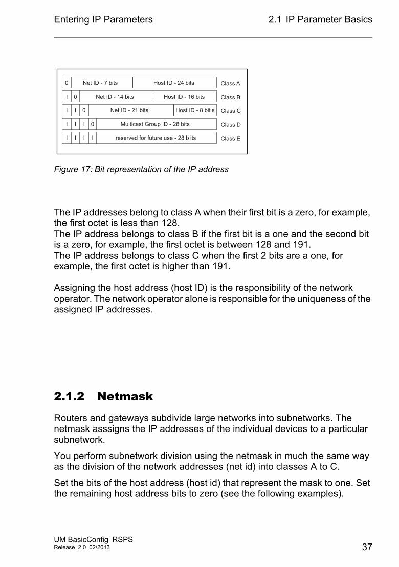
Figure 17: Bit representation of the IP address
The IP addresses belong to class A when their first bit is a zero, for example, the first octet is less than 128.The IP address belongs to class B if the first bit is a one and the second bit is a zero, for example, the first octet is between 128 and 191.The IP address belongs to class C when the first 2 bits are a one, for example, the first octet is higher than 191.
Assigning the host address (host ID) is the responsibility of the network operator. The network operator alone is responsible for the uniqueness of the assigned IP addresses.
2.1.2 Netmask
Routers and gateways subdivide large networks into subnetworks. The netmask asssigns the IP addresses of the individual devices to a particular subnetwork.
You perform subnetwork division using the netmask in much the same way as the division of the network addresses (net id) into classes A to C.
Set the bits of the host address (host id) that represent the mask to one. Set the remaining host address bits to zero (see the following examples).
Net ID - 7 bits Host ID - 24 bits0
I
I
I
0
I
I I I
0
I I I 0
Net ID - 14 bits
Net ID - 21 bits
Multicast Group ID - 28 bits
reserved for future use - 28 b its
Class A
Class BHost ID - 16 bits
Host ID - 8 bit s Class C
Class D
Class E
UM BasicConfig RSPSRelease 2.0 02/2013 37
Entering IP Parameters 2.1 IP Parameter Basics
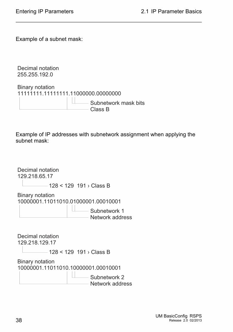
Example of a subnet mask:
Example of IP addresses with subnetwork assignment when applying the subnet mask:
255.255.192.0Decimal notation
11111111.11111111.11000000.00000000Binary notation
Subnetwork mask bitsClass B
129.218.65.17Decimal notation
10000001.11011010.01000001.00010001Binary notation
128 < 129 191 › Class B
Subnetwork 1Network address
129.218.129.17Decimal notation
10000001.11011010.10000001.00010001Binary notation
128 < 129 191 › Class B
Subnetwork 2Network address
38UM BasicConfig RSPS
Release 2.0 02/2013
Entering IP Parameters 2.1 IP Parameter Basics
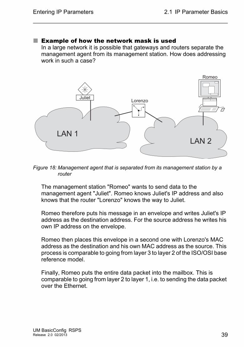
Example of how the network mask is usedIn a large network it is possible that gateways and routers separate the management agent from its management station. How does addressing work in such a case?
Figure 18: Management agent that is separated from its management station by a router
The management station "Romeo" wants to send data to the management agent "Juliet". Romeo knows Juliet's IP address and also knows that the router "Lorenzo" knows the way to Juliet.
Romeo therefore puts his message in an envelope and writes Juliet's IP address as the destination address. For the source address he writes his own IP address on the envelope.
Romeo then places this envelope in a second one with Lorenzo's MAC address as the destination and his own MAC address as the source. This process is comparable to going from layer 3 to layer 2 of the ISO/OSI base reference model.
Finally, Romeo puts the entire data packet into the mailbox. This is comparable to going from layer 2 to layer 1, i.e. to sending the data packet over the Ethernet.
Romeo
LAN 1
Lorenzo
LAN 2
Juliet
UM BasicConfig RSPSRelease 2.0 02/2013 39
Entering IP Parameters 2.1 IP Parameter Basics
Lorenzo receives the letter and removes the outer envelope. From the inner envelope he recognizes that the letter is meant for Juliet. He places the inner envelope in a new outer envelope and searches his address list (the ARP table) for Juliet's MAC address. He writes her MAC address on the outer envelope as the destination address and his own MAC address as the source address. He then places the entire data packet in the mail box.
Juliet receives the letter and removes the outer envelope. She finds the inner envelope with Romeo's IP address. Opening the inner envelope and reading its contents corresponds to transferring the message to the higher protocol layers of the SO/OSI layer model.
Juliet would now like to send a reply to Romeo. She places her reply in an envelope with Romeo's IP address as destination and her own IP address as source. But where is she to send the answer? For she did not receive Romeo's MAC address. It was lost when Lorenzo replaced the outer envelope.
In the MIB, Juliet finds Lorenzo listed under the variable hmNetGatewayIPAddr as a means of communicating with Romeo. She therefore puts the envelope with the IP addresses in a further envelope with Lorenzo's MAC destination address.
The letter now travels back to Romeo via Lorenzo, the same way the first letter traveled from Romeo to Juliet.
2.1.3 Classless Inter-Domain Routing
Class C with a maximum of 254 addresses was too small, and class B with a maximum of 65,534 addresses was too large for most users. Resulting in an ineffective usage of the available class B addresses.Class D contains reserved multicast addresses. Class E is for experimental purposes. A non-participating gateway ignores experimental datagrams with these destination addresses.
40UM BasicConfig RSPS
Release 2.0 02/2013
Entering IP Parameters 2.1 IP Parameter Basics
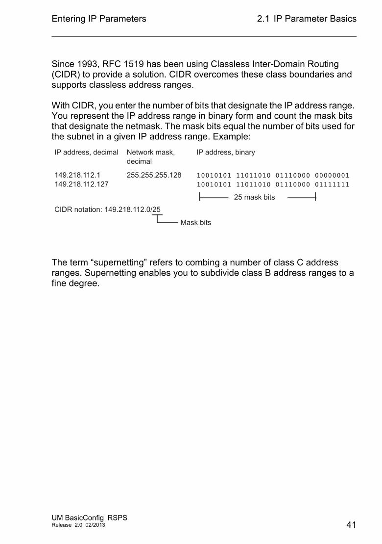
Since 1993, RFC 1519 has been using Classless Inter-Domain Routing (CIDR) to provide a solution. CIDR overcomes these class boundaries and supports classless address ranges.
With CIDR, you enter the number of bits that designate the IP address range. You represent the IP address range in binary form and count the mask bits that designate the netmask. The mask bits equal the number of bits used for the subnet in a given IP address range. Example:
The term “supernetting” refers to combing a number of class C address ranges. Supernetting enables you to subdivide class B address ranges to a fine degree.
IP address, decimal
149.218.112.1149.218.112.127
CIDR notation: 149.218.112.0/25
Mask bits
Network mask, decimal
255.255.255.128
IP address, binary
10010101 11011010 01110000 0000000110010101 11011010 01110000 01111111
25 mask bits
UM BasicConfig RSPSRelease 2.0 02/2013 41
Entering IP Parameters 2.2 Entering IP parameters via CLI
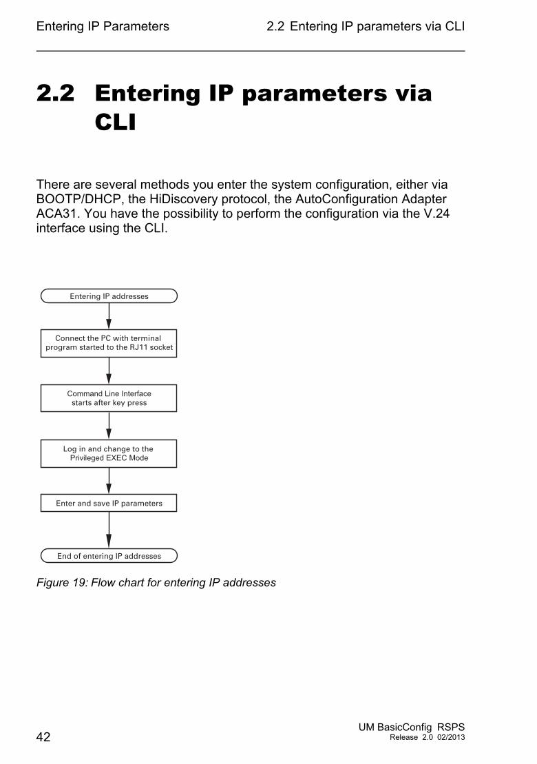
2.2 Entering IP parameters via CLI
There are several methods you enter the system configuration, either via BOOTP/DHCP, the HiDiscovery protocol, the AutoConfiguration Adapter ACA31. You have the possibility to perform the configuration via the V.24 interface using the CLI.
Figure 19: Flow chart for entering IP addresses
Entering IP addresses
Connect the PC with terminal program started to the RJ11 socket
Command Line Interfacestarts after key press
Log in and change to the Privileged EXEC Mode
Enter and save IP parameters
End of entering IP addresses
42UM BasicConfig RSPS
Release 2.0 02/2013
Entering IP Parameters 2.2 Entering IP parameters via CLI
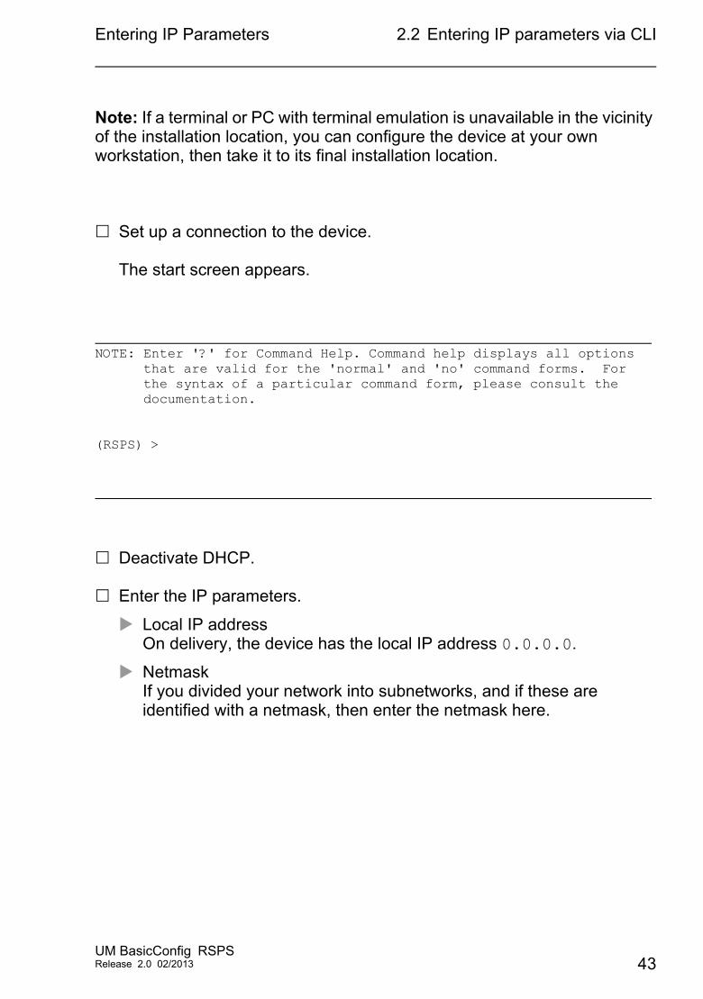
Note: If a terminal or PC with terminal emulation is unavailable in the vicinity of the installation location, you can configure the device at your own workstation, then take it to its final installation location.
Set up a connection to the device.
The start screen appears.
Deactivate DHCP.
Enter the IP parameters.
Local IP addressOn delivery, the device has the local IP address 0.0.0.0.
NetmaskIf you divided your network into subnetworks, and if these are identified with a netmask, then enter the netmask here.
NOTE: Enter '?' for Command Help. Command help displays all options that are valid for the 'normal' and 'no' command forms. For the syntax of a particular command form, please consult the documentation.
(RSPS) >
UM BasicConfig RSPSRelease 2.0 02/2013 43
Entering IP Parameters 2.2 Entering IP parameters via CLI
The default setting of the netmask is 0.0.0.0.
IP address of the gateway.You require this entry when installing the device in a different subnetwork as the management station or TFTP server (see page 39 “Example of how the network mask is used”).Enter the IP address of the gateway between the subnetwork with the device and the path to the management station.The default setting of the IP address is 0.0.0.0.
Save the configuration entered using copy config running-config nvm.
After entering the IP parameters, you easily configure the device via the graphical user interface (see the “GUI” reference manual).
enable Switch to the privileged EXEC mode.network protocol none Deactivate DHCP.network parms 10.0.1.23 255.255.255.0
Assign the device the IP address 10.0.1.23 and the netmask 255.255.255.0. You have the option of also assigning a gateway address.
copy config running-config nvm
Save the current configuration to the non-volatile memory.
44UM BasicConfig RSPS
Release 2.0 02/2013
Entering IP Parameters 2.3 Entering the IP Parameters viaHiDiscovery
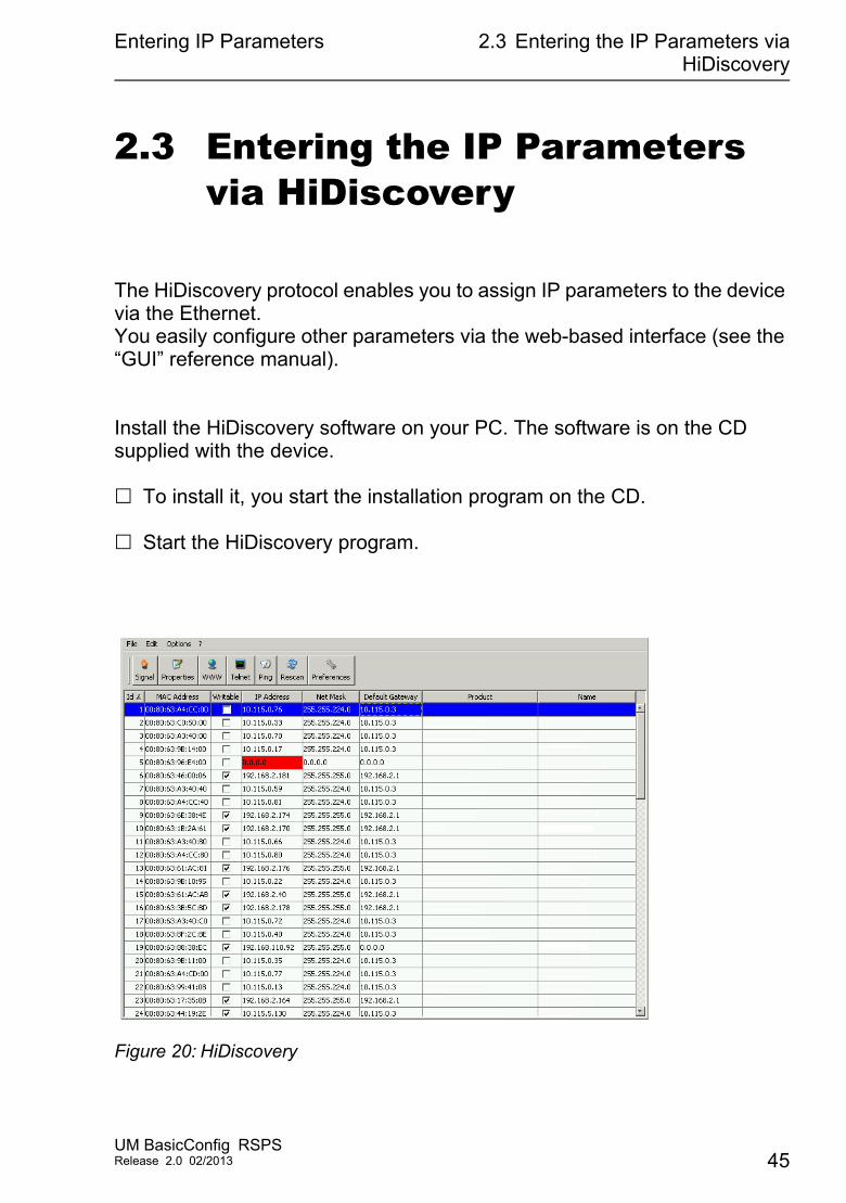
2.3 Entering the IP Parameters via HiDiscovery
The HiDiscovery protocol enables you to assign IP parameters to the device via the Ethernet.You easily configure other parameters via the web-based interface (see the “GUI” reference manual).
Install the HiDiscovery software on your PC. The software is on the CD supplied with the device.
To install it, you start the installation program on the CD.
Start the HiDiscovery program.
Figure 20: HiDiscovery
UM BasicConfig RSPSRelease 2.0 02/2013 45
Entering IP Parameters 2.3 Entering the IP Parameters viaHiDiscovery
When you start HiDiscovery, it automatically searches the network for those devices which support the HiDiscovery protocol.HiDiscovery uses the first network interface found for the PC. If your computer has several network cards, you select the one you desire in the HiDiscovery toolbar.
HiDiscovery displays a line for every device that reacts to the HiDiscovery protocol.
HiDiscovery enables you to identify the devices displayed.
Select a device line.
Click the „Signal“ symbol on the tool bar to set the LEDs for the selected device to flashing on. To switch off the flashing, click on the symbol again.
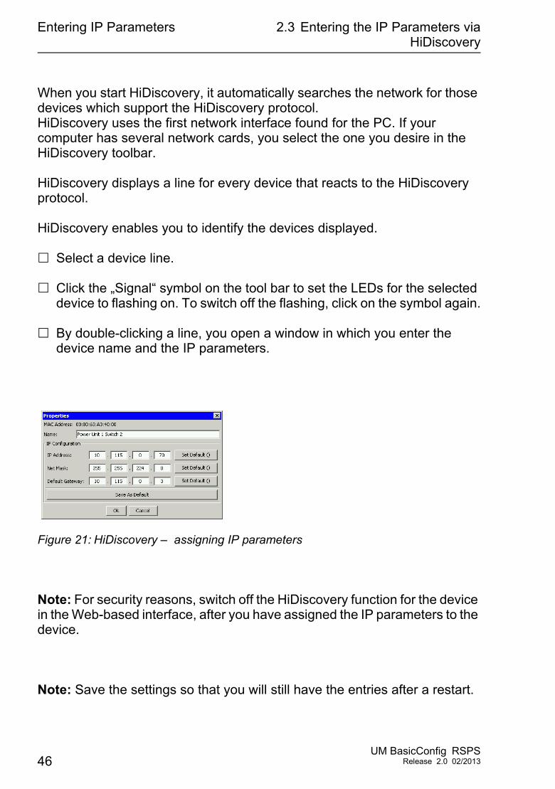
By double-clicking a line, you open a window in which you enter the device name and the IP parameters.
Figure 21: HiDiscovery – assigning IP parameters
Note: For security reasons, switch off the HiDiscovery function for the device in the Web-based interface, after you have assigned the IP parameters to the device.
Note: Save the settings so that you will still have the entries after a restart.
46UM BasicConfig RSPS
Release 2.0 02/2013
Entering IP Parameters 2.4 Enter the IP Parameter using theweb-based interface
2.4 Enter the IP Parameter using the web-based interface
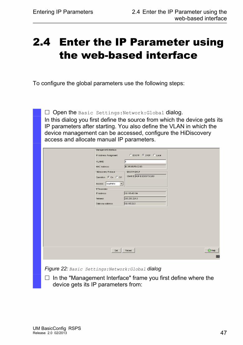
To configure the global parameters use the following steps:
Open the Basic Settings:Network:Global dialog.In this dialog you first define the source from which the device gets its IP parameters after starting. You also define the VLAN in which the device management can be accessed, configure the HiDiscovery access and allocate manual IP parameters.
Figure 22: Basic Settings:Network:Global dialog
In the "Management Interface" frame you first define where the device gets its IP parameters from:
UM BasicConfig RSPSRelease 2.0 02/2013 47
Entering IP Parameters 2.4 Enter the IP Parameter using theweb-based interface
In the "BOOTP" mode, the configuration is via a BOOTP or DHCP server on the basis of the MAC address of the device.
In the "DHCP" mode, the configuration is via a DHCP server on the basis of the MAC address or the name of the device.
In the "Local" mode, the device uses the network parameters from the internal device memory.
Note: When you change the allocation mode of the IP address, the device activates the new mode immediately after the "Write" button is pressed.
In the "VLAN ID" field you enter the ID of the VLAN in which the device management can be accessed via the network.
Note here that you can only access the management via device ports that are members of the relevant VLAN.
The "MAC address" field shows the MAC address of the device with which you access the device via the network. In the "HiDiscovery Protocol" frame you define the settings for
accessing the device via the HiDiscovery software. The HiDiscovery protocol allows you to allocate an IP address to the
device on the basis of its MAC address . Activate the HiDiscovery protocol if you want to allocate an IP address to the device from your PC with the supplied HiDiscovery software (default setting: "Admin Status" On, "Access" read-write).
If required, you can manually enter the IP address, the netmask and the gateway in the "IP Parameter" frame.
To temporarily save the changes, click "Set".Note: Um die Konfiguration auch nach einem Neustart noch verfügbar zu haben, speichern Sie die Einstellungen permanent über den Dialog Grundeinstellungen:Laden/Speichern.
48UM BasicConfig RSPS
Release 2.0 02/2013
Entering IP Parameters 2.5 Entering IP Parameters perBOOTP
2.5 Entering IP Parameters per BOOTP
With the BOOTP function activated the device sends a boot request message to the BOOTP server. The boot request message contains the Client ID configured in the Basic Settings:Network:Global dialog. The BOOTP server enters the Client ID into a database and assigns an IP address. The server answers with a boot reply message. The boot reply message contains the assigned IP address.
UM BasicConfig RSPSRelease 2.0 02/2013 49
Entering IP Parameters 2.6 Entering IP Parameters per DHCP
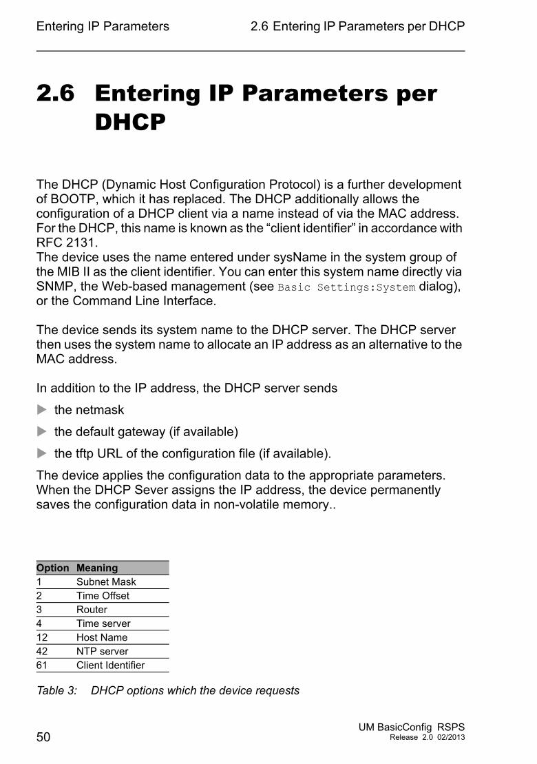
2.6 Entering IP Parameters per DHCP
The DHCP (Dynamic Host Configuration Protocol) is a further development of BOOTP, which it has replaced. The DHCP additionally allows the configuration of a DHCP client via a name instead of via the MAC address.For the DHCP, this name is known as the “client identifier” in accordance with RFC 2131.The device uses the name entered under sysName in the system group of the MIB II as the client identifier. You can enter this system name directly via SNMP, the Web-based management (see Basic Settings:System dialog), or the Command Line Interface.
The device sends its system name to the DHCP server. The DHCP server then uses the system name to allocate an IP address as an alternative to the MAC address.
In addition to the IP address, the DHCP server sends
the netmask
the default gateway (if available)
the tftp URL of the configuration file (if available).
The device applies the configuration data to the appropriate parameters. When the DHCP Sever assigns the IP address, the device permanently saves the configuration data in non-volatile memory..
Option Meaning1 Subnet Mask2 Time Offset3 Router4 Time server12 Host Name42 NTP server61 Client Identifier
Table 3: DHCP options which the device requests
50UM BasicConfig RSPS
Release 2.0 02/2013
Entering IP Parameters 2.6 Entering IP Parameters per DHCP
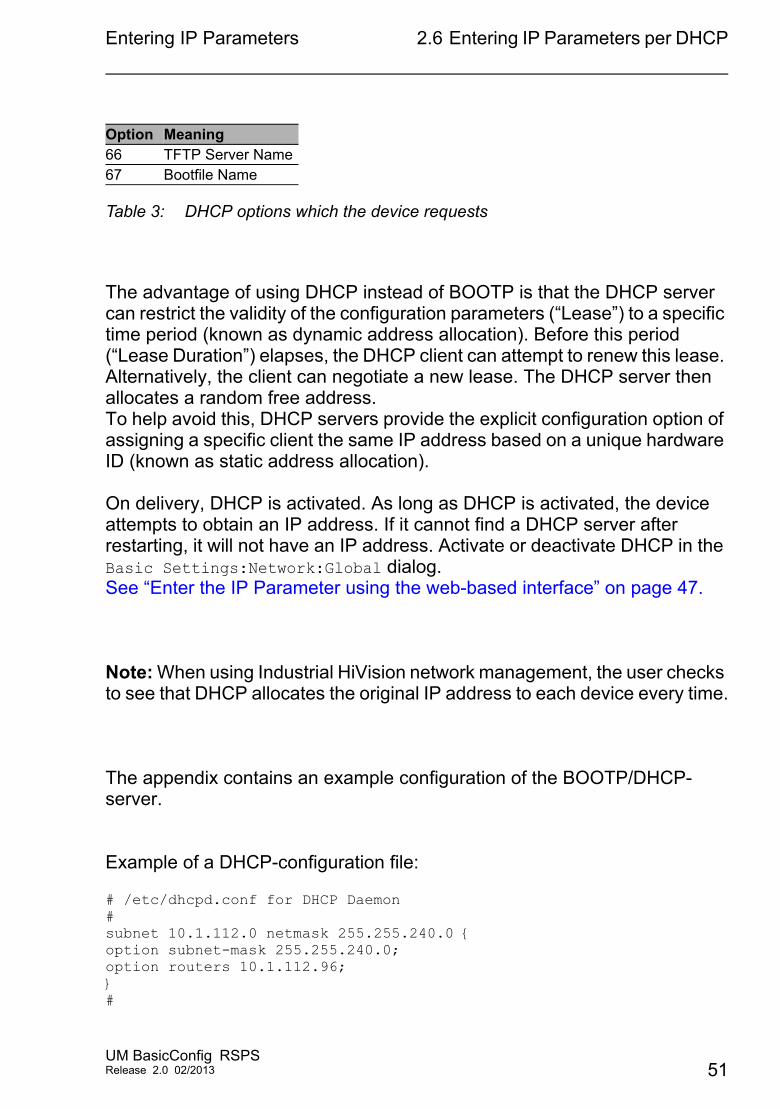
The advantage of using DHCP instead of BOOTP is that the DHCP server can restrict the validity of the configuration parameters (“Lease”) to a specific time period (known as dynamic address allocation). Before this period (“Lease Duration”) elapses, the DHCP client can attempt to renew this lease. Alternatively, the client can negotiate a new lease. The DHCP server then allocates a random free address.To help avoid this, DHCP servers provide the explicit configuration option of assigning a specific client the same IP address based on a unique hardware ID (known as static address allocation).
On delivery, DHCP is activated. As long as DHCP is activated, the device attempts to obtain an IP address. If it cannot find a DHCP server after restarting, it will not have an IP address. Activate or deactivate DHCP in the Basic Settings:Network:Global dialog.See “Enter the IP Parameter using the web-based interface” on page 47.
Note: When using Industrial HiVision network management, the user checks to see that DHCP allocates the original IP address to each device every time.
The appendix contains an example configuration of the BOOTP/DHCP-server.
Example of a DHCP-configuration file:
# /etc/dhcpd.conf for DHCP Daemon#subnet 10.1.112.0 netmask 255.255.240.0 {option subnet-mask 255.255.240.0;option routers 10.1.112.96;}#
66 TFTP Server Name67 Bootfile Name
Option Meaning
Table 3: DHCP options which the device requests
UM BasicConfig RSPSRelease 2.0 02/2013 51
Entering IP Parameters 2.6 Entering IP Parameters per DHCP
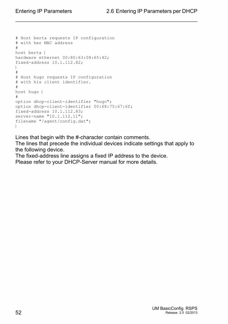
# Host berta requests IP configuration # with her MAC address# host berta {hardware ethernet 00:80:63:08:65:42;fixed-address 10.1.112.82;}# # Host hugo requests IP configuration # with his client identifier.# host hugo {#option dhcp-client-identifier "hugo";option dhcp-client-identifier 00:68:75:67:6f;fixed-address 10.1.112.83;server-name "10.1.112.11";filename "/agent/config.dat";}
Lines that begin with the #-character contain comments.The lines that precede the individual devices indicate settings that apply to the following device.The fixed-address line assigns a fixed IP address to the device.Please refer to your DHCP-Server manual for more details.
52UM BasicConfig RSPS
Release 2.0 02/2013
Entering IP Parameters 2.7 Management Address ConflictDetection
2.7 Management Address Conflict Detection
You assign an IP address to the device using several different methods. This function helps the device detect IP address conflicts on a network after boot up and the device also checks periodically during operation. This function is described in RFC 5227.
When enabled, the device sends an SNMP trap informing you that it detected an IP address conflict.
The follow list contains the default settings for this function: Operation setting:
– Operation: Enabled Configuration settings:
– Detection Mode: Active and Passive– Send Periodic ARP Probes: Enabled– Detection Delay [ms]: 200– Release Delay [s]: 15– Number of Address Protections: 3– Protection Interval [ms]: 200– Send Trap: Enabled
2.7.1 Active and Passive detection
Actively checking the network helps prevent the device from connecting to the network with a duplicate IP address. After connecting the device to a network or after configuring the IP address, the device immediately checks whether its IP address exists within the network. To check the network for address conflicts, the device sends 4 ARP probes with the detection delay of 200 ms into the network. If the IP address exists, the device returns to the previous configuration, if possible, and makes another check after the configured release delay time.
UM BasicConfig RSPSRelease 2.0 02/2013 53
Entering IP Parameters 2.7 Management Address ConflictDetection
When you disable active detection, the device sends 2 gratuitous APR announcements in 2 s intervals. Using the ARP announcements with passive detection enabled, the device polls the network to determine whether there is an address conflict. After resolving an address conflict or after expired release delay time, the device reconnects to the network. Following 10 detected conflicts, if the configured release delay interval is less than 60 s, then the device sets the release delay interval to 60 s.
After the device performs active detection or you disable the active detection function, with passive detection enabled the device listens on the network for other devices using the same IP address. If the device detects a duplicate IP address, it initially defends its address by employing the ACD mechanism in the passive detection mode and sends out gratuitous ARPs. The number of protections that the device sends and the protection interval are configurable. To resolve conflicts, if the remote device remains connected to the network, the network interface of the local device disconnects from the network.
When a DHCP server assigns an IP address to the device, the device returns a DHCP decline message when an address conflict occurs.
The device uses the ARP probe method which has the following advantages: ARP caches on other devices remain unchanged the method is robust through multiple ARP probe transmissions
54UM BasicConfig RSPS
Release 2.0 02/2013

Access to the device
3 Access to the device
UM BasicConfig RSPSRelease 2.0 02/2013 55
Access to the device 3.1 Authentication lists
3.1 Authentication lists
The device allows you to use authentication lists to specify which method it uses for the authentication. For every application with which someone accesses the device, a separate policy is possible.
3.1.1 Applications
The device supports the following applications, with which the device management can be accessed: Access using CLI via a serial connection Access using CLI via SSH Access using CLI via Telnet Access using the graphical user interface (GUI)
3.1.2 Methods
When users login, the device uses one of the following methods for the authentication: local
The device authenticates the users by using the local user management - see the Security:User Management dialog.
radiusThe device forwards authentication requests to a RADIUS server in the network.
56UM BasicConfig RSPS
Release 2.0 02/2013
Access to the device 3.1 Authentication lists
3.1.3 Default setting
In the default settings of the device, the following lists are already set up and active: defaultLoginAuthList
This list specifies the methods for the authentication for users that log in using the graphical user interface (GUI) or using the CLI via SSH or Telnet. The SSH, Telnet and Web Interface applications are allocated to the list
defaultV24AuthListThis list specifies the methods for the authentication for users that log in using the CLI via a serial connection. The Console(V.24) application is allocated to the list.
UM BasicConfig RSPSRelease 2.0 02/2013 57
Access to the device 3.1 Authentication lists
3.1.4 Managing authentication lists
You manage the authentication lists in the graphical user interface (GUI) or in the CLI.
Prerequisite: User account with authorization profile administrator.
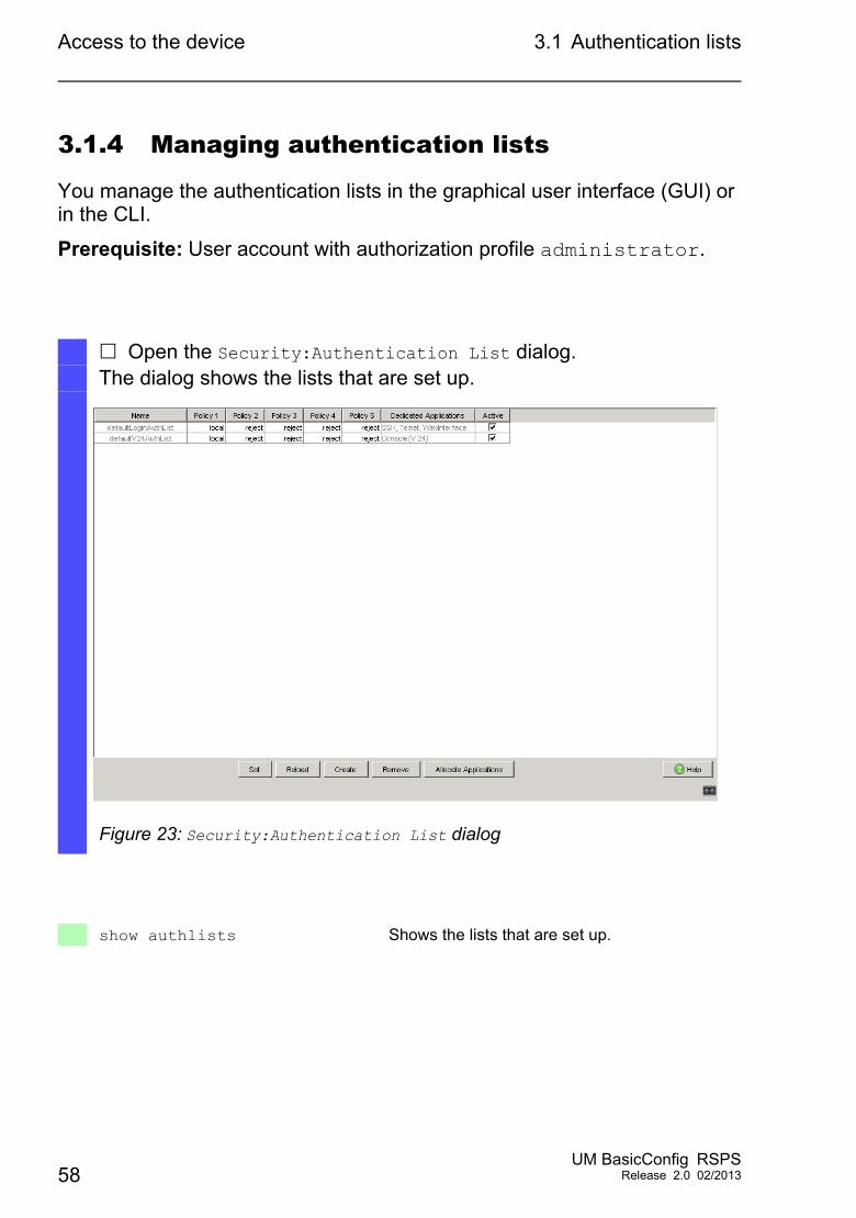
Open the Security:Authentication List dialog.The dialog shows the lists that are set up.
Figure 23: Security:Authentication List dialog
show authlists Shows the lists that are set up.
58UM BasicConfig RSPS
Release 2.0 02/2013
Access to the device 3.1 Authentication lists
3.1.5 Adjusting the settings
The device allows you to allocate a separate policy for the authentication to every application with which someone accesses the device.
In the following example, we will set up a separate list for each of the applications included in the default list defaultLoginAuthList.
Prerequisite: User account with authorization profile administrator.
Perform the following work steps:
Create new lists.
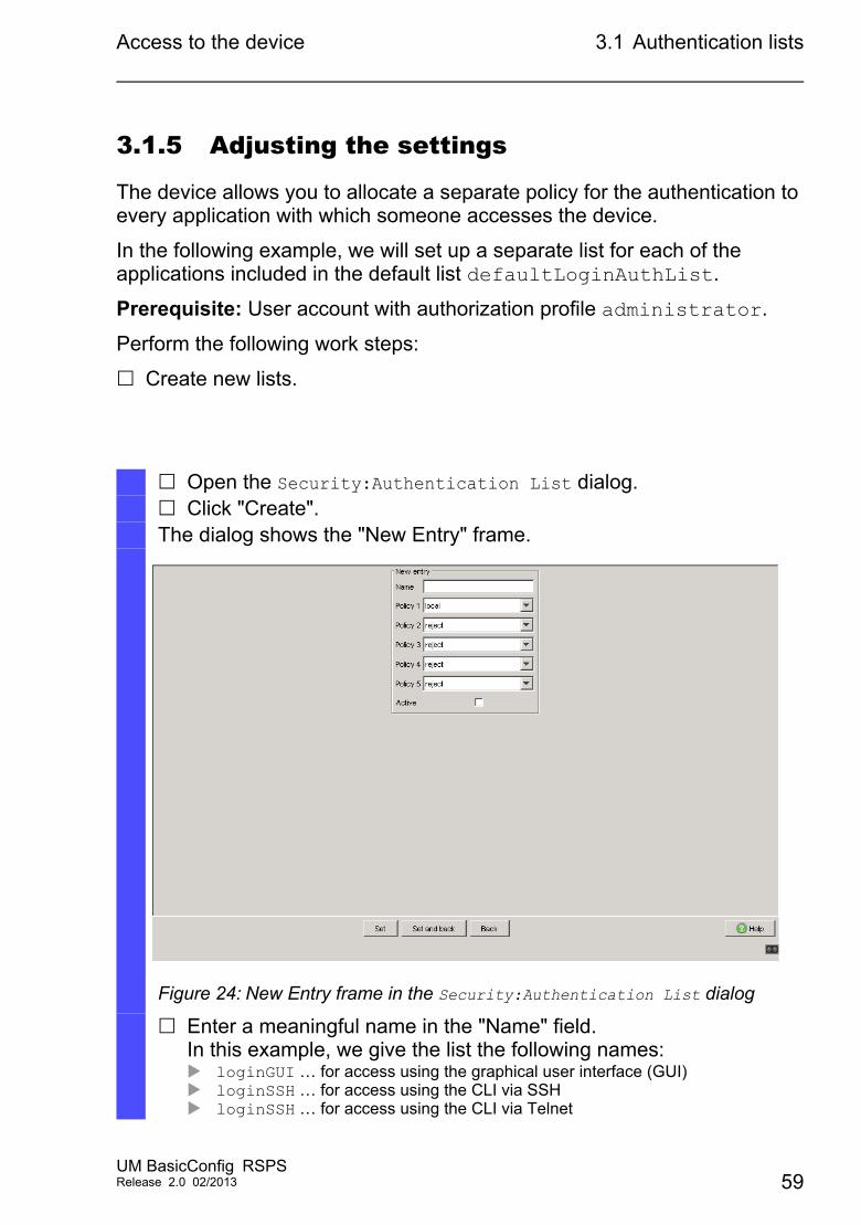
Open the Security:Authentication List dialog. Click "Create".The dialog shows the "New Entry" frame.
Figure 24: New Entry frame in the Security:Authentication List dialog
Enter a meaningful name in the "Name" field.In this example, we give the list the following names: loginGUI … for access using the graphical user interface (GUI) loginSSH … for access using the CLI via SSH loginSSH … for access using the CLI via Telnet
UM BasicConfig RSPSRelease 2.0 02/2013 59
Access to the device 3.1 Authentication lists
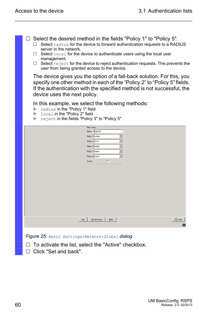
Select the desired method in the fields "Policy 1" to "Policy 5". Select radius for the device to forward authentication requests to a RADIUS
server in the network. Select local for the device to authenticate users using the local user
management. Select reject for the device to reject authentication requests. This prevents the
user from being granted access to the device.
The device gives you the option of a fall-back solution. For this, you specify one other method in each of the “Policy 2” to “Policy 5” fields. If the authentication with the specified method is not successful, the device uses the next policy.
In this example, we select the following methods: radius in the "Policy 1" field local in the "Policy 2" field reject in the fields "Policy 3" to "Policy 5"
Figure 25: Basic Settings:Network:Global dialog
To activate the list, select the "Active" checkbox. Click "Set and back".
60UM BasicConfig RSPS
Release 2.0 02/2013
Access to the device 3.1 Authentication lists
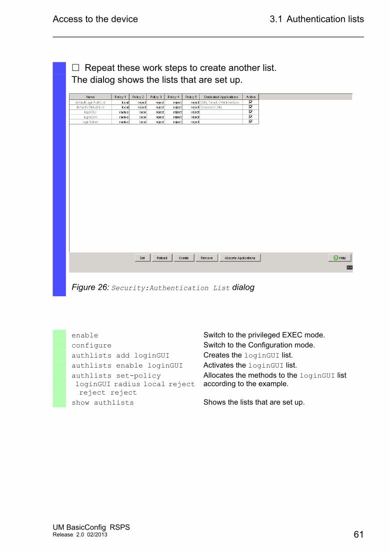
Repeat these work steps to create another list.The dialog shows the lists that are set up.
Figure 26: Security:Authentication List dialog
enable Switch to the privileged EXEC mode.configure Switch to the Configuration mode.authlists add loginGUI Creates the loginGUI list.authlists enable loginGUI Activates the loginGUI list.authlists set-policy loginGUI radius local reject reject reject
Allocates the methods to the loginGUI list according to the example.
show authlists Shows the lists that are set up.
UM BasicConfig RSPSRelease 2.0 02/2013 61
Access to the device 3.1 Authentication lists
Connect the list with an application.
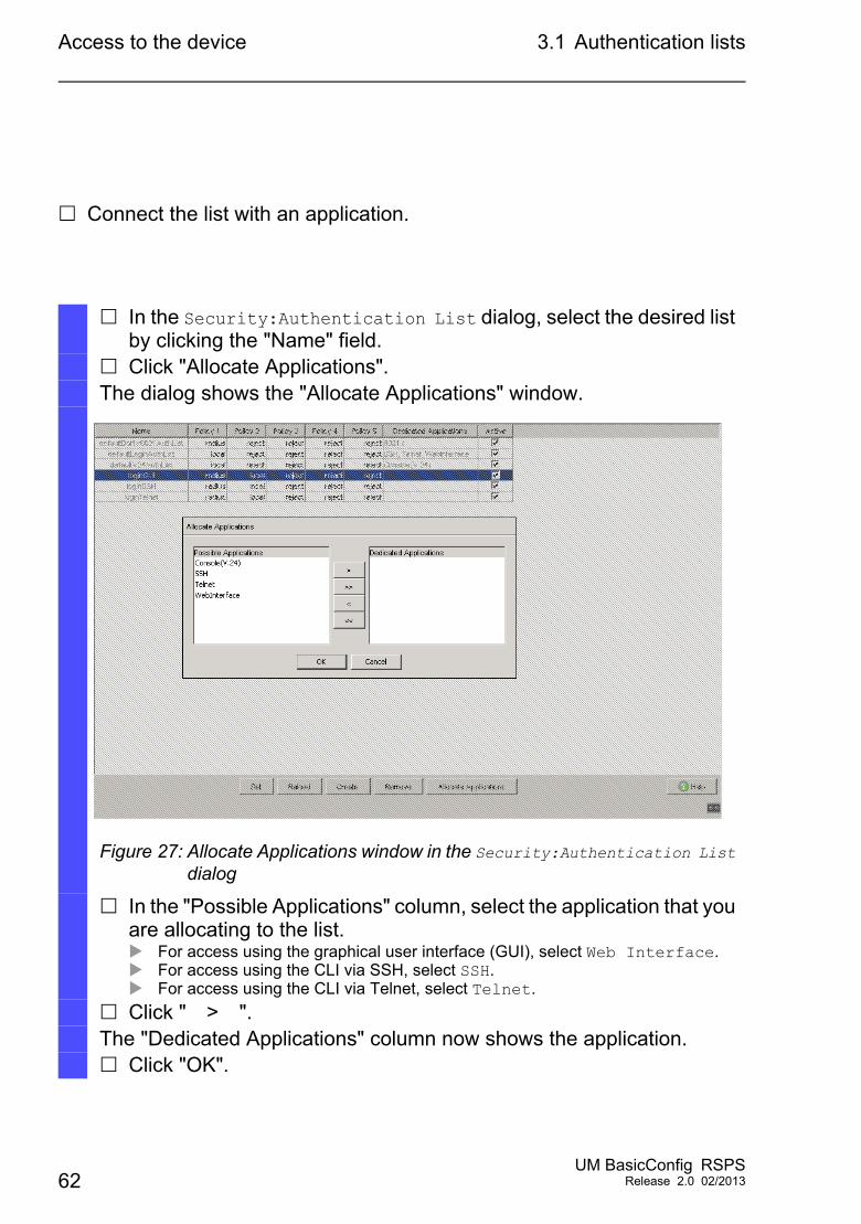
In the Security:Authentication List dialog, select the desired list by clicking the "Name" field.
Click "Allocate Applications".The dialog shows the "Allocate Applications" window.
Figure 27: Allocate Applications window in the Security:Authentication List dialog
In the "Possible Applications" column, select the application that you are allocating to the list. For access using the graphical user interface (GUI), select Web Interface. For access using the CLI via SSH, select SSH. For access using the CLI via Telnet, select Telnet.
Click " > ".The "Dedicated Applications" column now shows the application. Click "OK".
62UM BasicConfig RSPS
Release 2.0 02/2013
Access to the device 3.1 Authentication lists
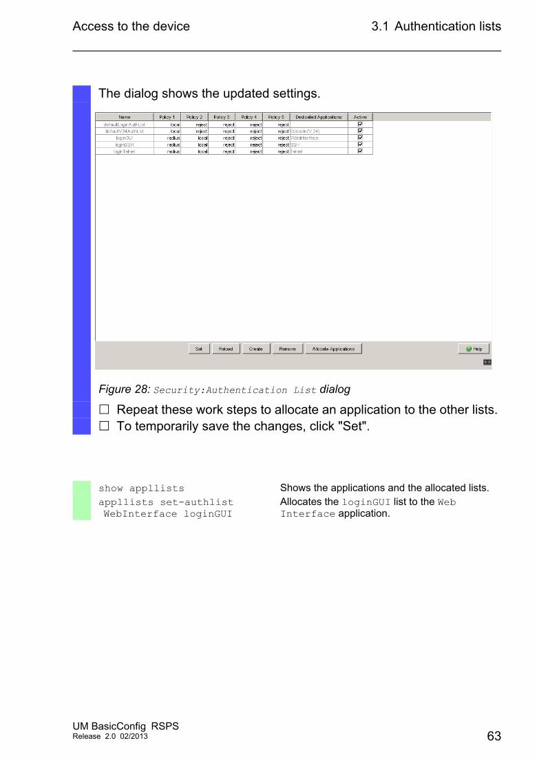
The dialog shows the updated settings.
Figure 28: Security:Authentication List dialog
Repeat these work steps to allocate an application to the other lists. To temporarily save the changes, click "Set".
show appllists Shows the applications and the allocated lists.appllists set-authlist WebInterface loginGUI
Allocates the loginGUI list to the Web Interface application.
UM BasicConfig RSPSRelease 2.0 02/2013 63
Access to the device 3.1 Authentication lists
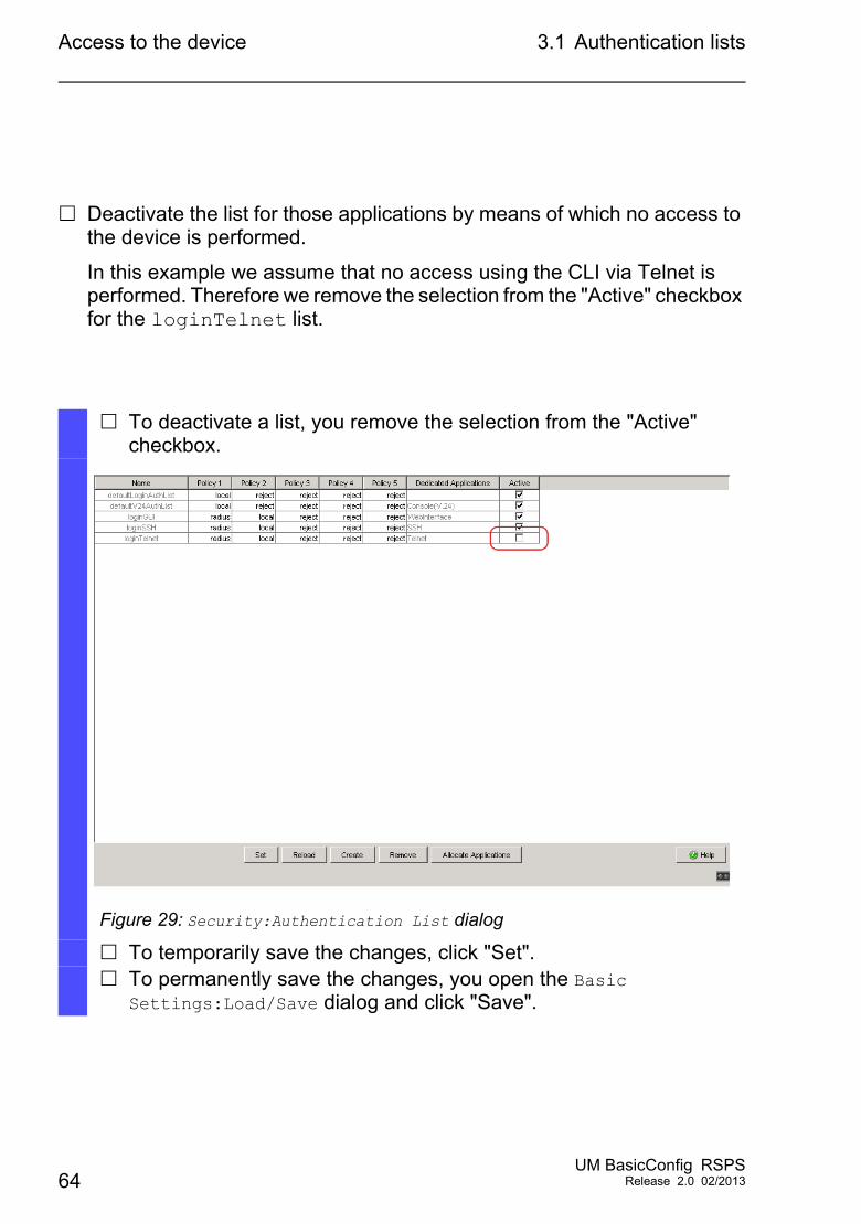
Deactivate the list for those applications by means of which no access to the device is performed.
In this example we assume that no access using the CLI via Telnet is performed. Therefore we remove the selection from the "Active" checkbox for the loginTelnet list.
To deactivate a list, you remove the selection from the "Active" checkbox.
Figure 29: Security:Authentication List dialog
To temporarily save the changes, click "Set". To permanently save the changes, you open the Basic
Settings:Load/Save dialog and click "Save".
64UM BasicConfig RSPS
Release 2.0 02/2013
Access to the device 3.1 Authentication lists
authlists disable loginTelnet
Deactivates the loginTelnet list.
save Saves the settings in the non-volatile memory of the device (NVM) in the “selected” configuration profile.
UM BasicConfig RSPSRelease 2.0 02/2013 65
Access to the device 3.2 User Management
3.2 User Management
The device allows users to access its management functions when they log in with valid login data. The device authenticates the users either using the local user management or with a RADIUS server in the network. To get the device to use the user management, allocate the local method to an authentication list - see the Security:Authentication List dialog.
In the local user management, you manage the user accounts. One user account is usually allocated to each user.
3.2.1 Privilege Levels
The device allows you to use a role-based authorization model to specifically control the access to the management functions. Users to whom a specific authorization profile is allocated are allowed to use commands and functions from the same authorization profile or a lower one.
The device uses the authorization profiles on all applications with which the management functions can be accessed.
66UM BasicConfig RSPS
Release 2.0 02/2013
Access to the device 3.2 User Management
Every user account is linked to an authorization profile that regulates the access to the individual functions of the device. Depending on the planned activity for the respective user, you assign a predefined authorization profile to the user. The device differentiates between the following authorization profiles.
Authorization Description Authorized for the following activitiesAdministrator The user is authorized to
monitor and administer the device.
All activities with read/write access, including the following activities reserved for an administrator: Add, modify or delete user accounts Activate, deactivate or unlock user
accounts Change all passwords Configure password management Set or change system time Load files to the device, e.g. device
configurations, certificates or software images
Reset settings and security-related settings to the state on delivery
Configure RADIUS server and authentication lists
Apply CLI scripts Switch CLI logging and SNMP logging
on and off External memory activation and
deactivation System monitor activation and
deactivation Switch the services for the management
access (e. g. SNMP) on and off. Configure access restrictions to the user
interfaces or the CLI based on the IP addresses
Operator The user is authorized to monitor and configure the device - with the exception of security-related settings.
All activities with read/write access, with the exception of the above-named activities, which are reserved for an administrator:
Table 4: Authorization profiles for user accounts
UM BasicConfig RSPSRelease 2.0 02/2013 67
Access to the device 3.2 User Management
3.2.2 Managing user accounts
You manage the user accounts in the graphical user interface (GUI) or in the CLI.
Prerequisite: User account with authorization profile administrator.
Guest The user is authorized to monitor the device - with the exception of security-related settings.
Monitoring activtities with read access.
Unauthorized No access to the device possible. As an administrator you
assign this authorization to temporarily lock a user account.
The device assigns this authorization to a user account if an error occurs when assigning a different authorization profile.
No activities allowed.
Open the Security:User Management dialog.
Authorization Description Authorized for the following activities
Table 4: Authorization profiles for user accounts (cont.)
68UM BasicConfig RSPS
Release 2.0 02/2013
Access to the device 3.2 User Management
The dialog shows the user accounts that are set up.
Figure 30: Security:User Management dialog
show users Shows the user accounts that are set up.
UM BasicConfig RSPSRelease 2.0 02/2013 69
Access to the device 3.2 User Management
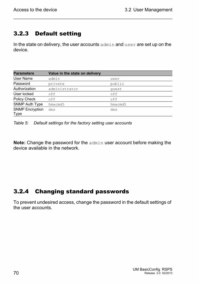
3.2.3 Default setting
In the state on delivery, the user accounts admin and user are set up on the device.
Note: Change the password for the admin user account before making the device available in the network.
3.2.4 Changing standard passwords
To prevent undesired access, change the password in the default settings of the user accounts.
Parameters Value in the state on deliveryUser Name admin userPassword private publicAuthorization administrator guestUser locked off offPolicy Check off offSNMP Auth Type hmacmd5 hmacmd5SNMP Encryption Type
des des
Table 5: Default settings for the factory setting user accounts
70UM BasicConfig RSPS
Release 2.0 02/2013
Access to the device 3.2 User Management
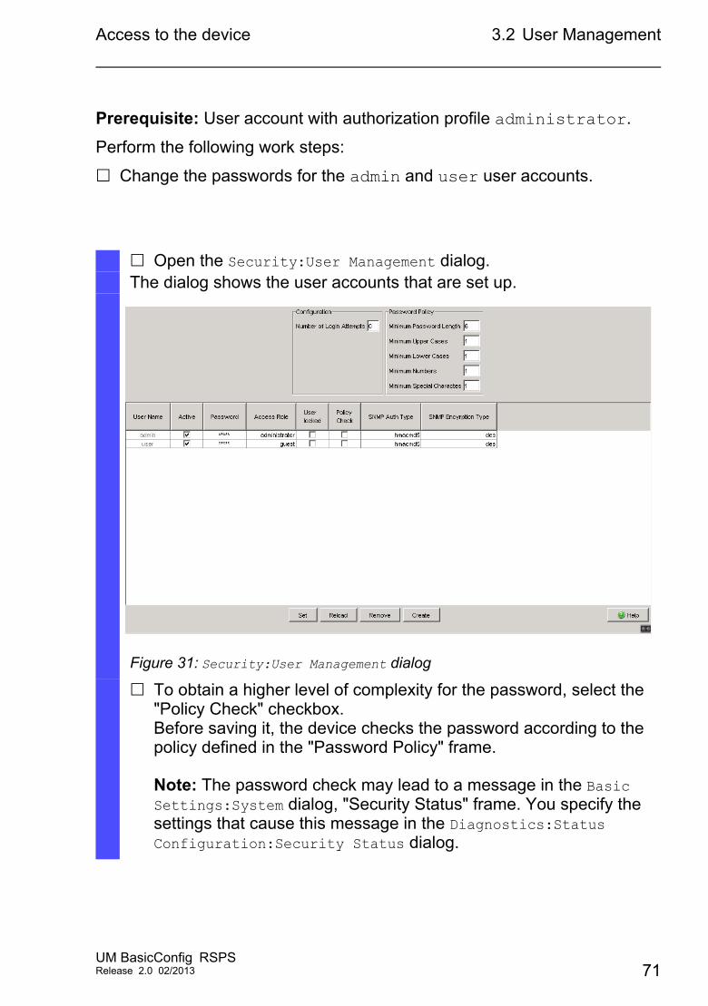
Prerequisite: User account with authorization profile administrator.
Perform the following work steps:
Change the passwords for the admin and user user accounts.
Open the Security:User Management dialog.The dialog shows the user accounts that are set up.
Figure 31: Security:User Management dialog
To obtain a higher level of complexity for the password, select the "Policy Check" checkbox.Before saving it, the device checks the password according to the policy defined in the "Password Policy" frame.
Note: The password check may lead to a message in the Basic Settings:System dialog, "Security Status" frame. You specify the settings that cause this message in the Diagnostics:Status Configuration:Security Status dialog.
UM BasicConfig RSPSRelease 2.0 02/2013 71
Access to the device 3.2 User Management
Click the row of the relevant user account in the "Password" field. Enter a password of at least 6 characters.Up to 64 alphanumeric characters are allowed. The device differentiates between upper and lower case. The minimum length of the password is defined in the "Password Policy" frame.
The device always checks the minimum length of the password.
To temporarily save the changes, click "Set". To permanently save the changes, you open the Basic
Settings:Load/Save dialog and click "Save".
enable Switch to the privileged EXEC mode.configure Switch to the Configuration mode.users password-policy-check <user> enable
Activates the checking of the password for the <user> user account based on the specified policy. In this way, you obtain a higher level of complexity for the password.
Note: The password check may lead to a message when you display the security status (show security-status all). You specify the settings that cause this message with the command security-status monitor bypass-pwd-strength.
users password <user> SECRET Specifies the password “SECRET” for the <user> user account. Enter at least 6 characters.
save Saves the settings in the non-volatile memory of the device (NVM) in the “selected” configuration profile.
72UM BasicConfig RSPS
Release 2.0 02/2013
Access to the device 3.2 User Management
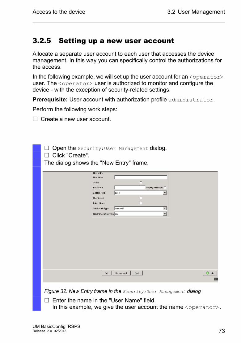
3.2.5 Setting up a new user account
Allocate a separate user account to each user that accesses the device management. In this way you can specifically control the authorizations for the access.
In the following example, we will set up the user account for an <operator> user. The <operator> user is authorized to monitor and configure the device - with the exception of security-related settings.
Prerequisite: User account with authorization profile administrator.
Perform the following work steps:
Create a new user account.
Open the Security:User Management dialog. Click "Create".The dialog shows the "New Entry" frame.
Figure 32: New Entry frame in the Security:User Management dialog
Enter the name in the "User Name" field.In this example, we give the user account the name <operator>.
UM BasicConfig RSPSRelease 2.0 02/2013 73
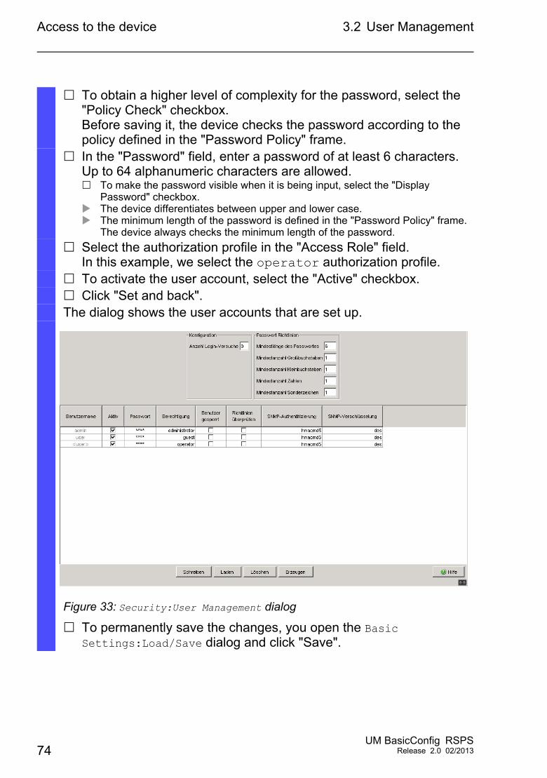
Access to the device 3.2 User Management
To obtain a higher level of complexity for the password, select the "Policy Check" checkbox.Before saving it, the device checks the password according to the policy defined in the "Password Policy" frame.
In the "Password" field, enter a password of at least 6 characters.Up to 64 alphanumeric characters are allowed. To make the password visible when it is being input, select the "Display
Password" checkbox. The device differentiates between upper and lower case. The minimum length of the password is defined in the "Password Policy" frame.
The device always checks the minimum length of the password.
Select the authorization profile in the "Access Role" field.In this example, we select the operator authorization profile.
To activate the user account, select the "Active" checkbox. Click "Set and back".The dialog shows the user accounts that are set up.
Figure 33: Security:User Management dialog
To permanently save the changes, you open the Basic Settings:Load/Save dialog and click "Save".
74UM BasicConfig RSPS
Release 2.0 02/2013
Access to the device 3.2 User Management
Note: Remember to allocate the password when you are setting up a new user account in the CLI.
enable Switch to the privileged EXEC mode.configure Switch to the Configuration mode.users add <operator> Creates the <operator> user account.users password-policy-check <operator> enable
Activates the checking of the password for the <operator> user account based on the specified policy. In this way, you obtain a higher level of complexity for the password.
users password <operator> SECRET
Specifies the password “SECRET” for the <operator> user account. Enter at least 6 characters.
users access-role <operator> operator
Allocates the operator authorization profile to the <operator> user account.
users enable <operator> Activates the <operator> user account.show users Shows the user accounts that are set up.save Saves the settings in the non-volatile memory of
the device (NVM) in the “selected” configuration profile.
UM BasicConfig RSPSRelease 2.0 02/2013 75
Access to the device 3.2 User Management
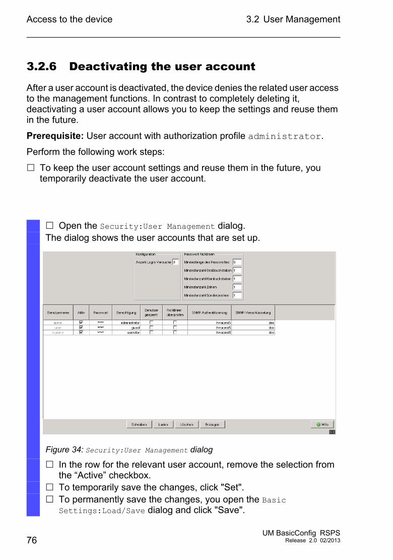
3.2.6 Deactivating the user account
After a user account is deactivated, the device denies the related user access to the management functions. In contrast to completely deleting it, deactivating a user account allows you to keep the settings and reuse them in the future.
Prerequisite: User account with authorization profile administrator.
Perform the following work steps:
To keep the user account settings and reuse them in the future, you temporarily deactivate the user account.
Open the Security:User Management dialog.The dialog shows the user accounts that are set up.
Figure 34: Security:User Management dialog
In the row for the relevant user account, remove the selection from the “Active” checkbox.
To temporarily save the changes, click "Set". To permanently save the changes, you open the Basic
Settings:Load/Save dialog and click "Save".
76UM BasicConfig RSPS
Release 2.0 02/2013
Access to the device 3.2 User Management
To permanently deactivate the user account settings, you delete the user account.
3.2.7 Adjusting policies for passwords
The device allows you to check whether the passwords for the user accounts adhere to the specified policy. You obtain a higher level of complexity for the passwords when they adhere to the policy.
The user management of the device allows you to activate or deactivate the check separately in each user account. When the check is activated, the device accepts a changed password only if it fulfills the requirements of the policy.
enable Switch to the privileged EXEC mode.configure Switch to the Configuration mode.users disable <user> To disable user account.show users Shows the user accounts that are set up.save Saves the settings in the non-volatile memory of
the device (NVM) in the “selected” configuration profile.
Select the relevant user and click "Clear". To permanently save the changes, you open the Basic
Settings:Load/Save dialog and click "Save".
users delete <user> Deletes the <user> user account.show users Shows the user accounts that are set up.save Saves the settings in the non-volatile memory of
the device (NVM) in the “selected” configuration profile.
UM BasicConfig RSPSRelease 2.0 02/2013 77
Access to the device 3.2 User Management
In the default settings, practical values for the policy are set up on the device. You have the option of adjusting the policy to meet your requirements.
Prerequisite: User account with authorization profile administrator.
Perform the following work steps:
Adjust the policy for passwords to meet your requirements.
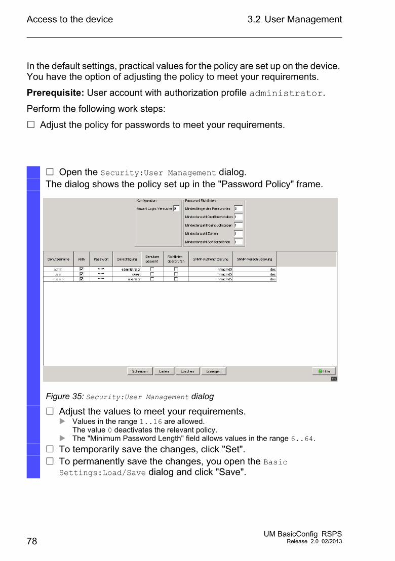
Open the Security:User Management dialog.The dialog shows the policy set up in the "Password Policy" frame.
Figure 35: Security:User Management dialog
Adjust the values to meet your requirements. Values in the range 1..16 are allowed.
The value 0 deactivates the relevant policy. The "Minimum Password Length" field allows values in the range 6..64.
To temporarily save the changes, click "Set". To permanently save the changes, you open the Basic
Settings:Load/Save dialog and click "Save".
78UM BasicConfig RSPS
Release 2.0 02/2013
Access to the device 3.2 User Management
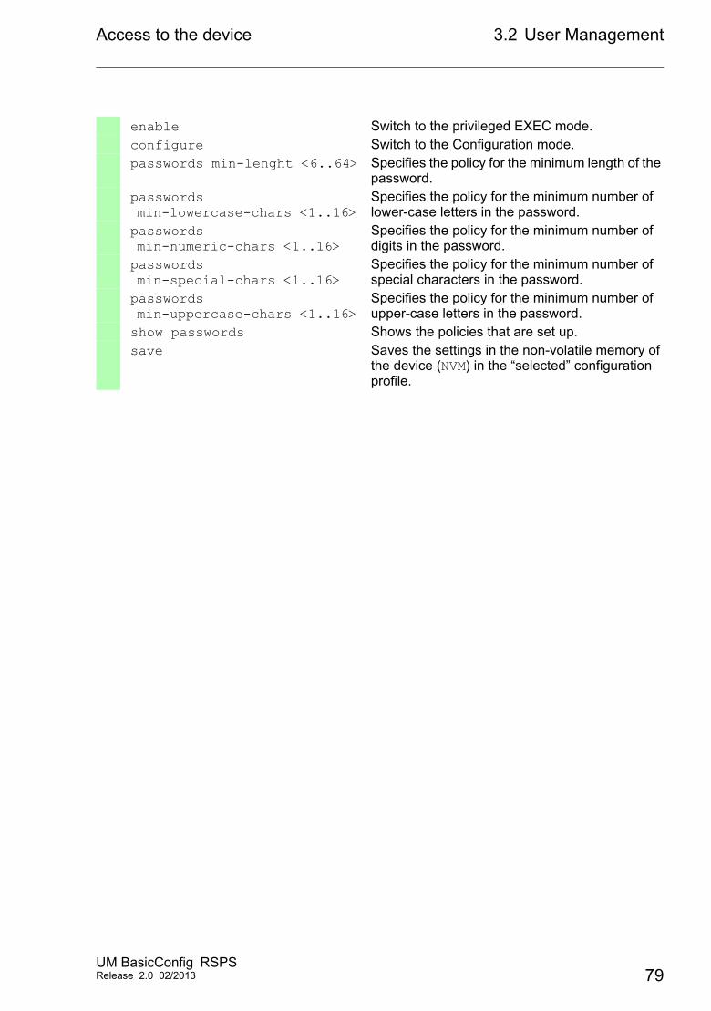
enable Switch to the privileged EXEC mode.configure Switch to the Configuration mode.passwords min-lenght <6..64> Specifies the policy for the minimum length of the
password.passwords min-lowercase-chars <1..16>
Specifies the policy for the minimum number of lower-case letters in the password.
passwords min-numeric-chars <1..16>
Specifies the policy for the minimum number of digits in the password.
passwords min-special-chars <1..16>
Specifies the policy for the minimum number of special characters in the password.
passwords min-uppercase-chars <1..16>
Specifies the policy for the minimum number of upper-case letters in the password.
show passwords Shows the policies that are set up.save Saves the settings in the non-volatile memory of
the device (NVM) in the “selected” configuration profile.
UM BasicConfig RSPSRelease 2.0 02/2013 79
Access to the device 3.3 SNMP Access
3.3 SNMP Access
3.3.1 SNMPv1/v2 Community
The SNMP protocol allows you to monitor and configure the device via the network with a network management system (NMS). When the NMS accesses the device via SNMPv1 or SNMPv2, the NMS authenticates itself with the community.
With the default settings, you access the device via the public (read access) and private (read/write access) communities.
The community is contained in every SNMP packet. When it receives a packet, the device compares this community with the communities specified in the device. If the communities match, the device accepts the SNMP packet and grants access.
Make the following basic provisions to make undesired access to the device more difficult:
Change the community for read/write access. Treat this community confidentially. Everyone who knows the community has the option to change the settings for the device.
Specify a different community for read/write access than for read access.
Use SNMPv1 or SNMPv2 only in environments protected from eavesdropping. The protocols do not use encryption. The SNMP packets contain the community in clear text. We recommend using SNMPv3 and deactivating the access via SNMPv1 and SNMPv2 in the device.
80UM BasicConfig RSPS
Release 2.0 02/2013
Access to the device 3.3 SNMP Access
Prerequisite: User account with authorization profile administrator.
Perform the following work steps:
Change the community for read/write access.
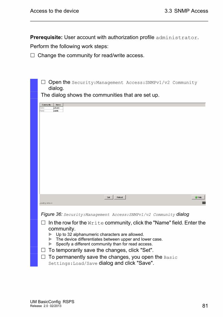
Open the Security:Management Access:SNMPv1/v2 Community dialog.
The dialog shows the communities that are set up.
Figure 36: Security:Management Access:SNMPv1/v2 Community dialog
In the row for the Write community, click the "Name" field. Enter the community. Up to 32 alphanumeric characters are allowed. The device differentiates between upper and lower case. Specify a different community than for read access.
To temporarily save the changes, click "Set". To permanently save the changes, you open the Basic
Settings:Load/Save dialog and click "Save".
UM BasicConfig RSPSRelease 2.0 02/2013 81
Access to the device 3.3 SNMP Access
Deactivate the access via SNMPv1 or SNMPv2 in the device.
enable Switch to the privileged EXEC mode.configure Switch to the Configuration mode.snmp community rw <community name>
Specifies the community for read/write access.
show snmp community Shows the communities that are set up.save Saves the settings in the non-volatile memory of
the device (NVM) in the “selected” configuration profile.
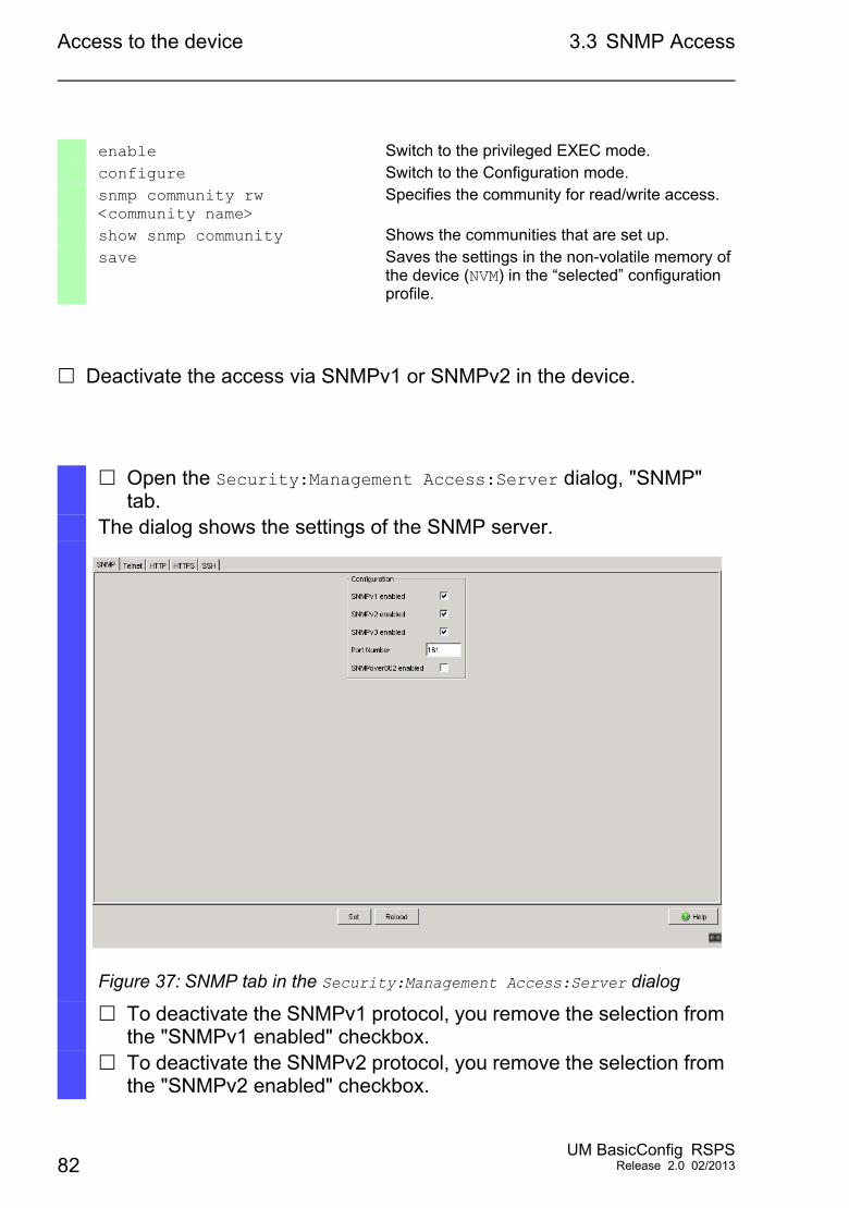
Open the Security:Management Access:Server dialog, "SNMP" tab.
The dialog shows the settings of the SNMP server.
Figure 37: SNMP tab in the Security:Management Access:Server dialog
To deactivate the SNMPv1 protocol, you remove the selection from the "SNMPv1 enabled" checkbox.
To deactivate the SNMPv2 protocol, you remove the selection from the "SNMPv2 enabled" checkbox.
82UM BasicConfig RSPS
Release 2.0 02/2013
Access to the device 3.3 SNMP Access
To temporarily save the changes, click "Set". To permanently save the changes, you open the Basic
Settings:Load/Save dialog and click "Save".
enable Switch to the privileged EXEC mode.configure Switch to the Configuration mode.no snmp access version v1 Deactivates the SNMPv1 protocol.no snmp access version v2 Deactivates the SNMPv2 protocol.show snmp access Shows the settings of the SNMP server.save Saves the settings in the non-volatile memory of
the device (NVM) in the “selected” configuration profile.
UM BasicConfig RSPSRelease 2.0 02/2013 83
Access to the device 3.3 SNMP Access
3.3.2 SNMPv3 access
The SNMP protocol allows you to monitor and configure the device via the network with a network management system (NMS). When the NMS accesses the device via SNMPv3, the NMS authenticates itself with a user’s login data.
The prerequisite for network management access is that the same SNMPv3 parameters are specified in the device and in the NMS. When a new user account is being set up in the device, the default
settings for the "SNMP Auth Type" and "SNMP Encryption Type" parameters are such that the Industrial HiVision network management software can access the device with it immediately.
To monitor or configure the device with a different NMS, you adjust the following parameters in the relevant user account to match the settings in your NMS.
"SNMP Auth Type" parameter– hmacmd5
Authentication with HMAC-MD5– hmacsha
Authentication with HMAC-SHA
"SNMP Encryption Type" parameter– none
Authentication unencrypted– des
Authentication encrypted with DES– aesCfb128
Authentication encrypted with AES-128 in Cipher Feedback mode.
84UM BasicConfig RSPS
Release 2.0 02/2013
Access to the device 3.3 SNMP Access
The device allows you to specify the "SNMP Auth Type" and "SNMP Encryption Type" parameters individually in each user account.
Prerequisite: User account with authorization profile administrator.
Perform the following work steps:
Adjust the SNMPv3 parameters in the user account to match the settings in your NMS.
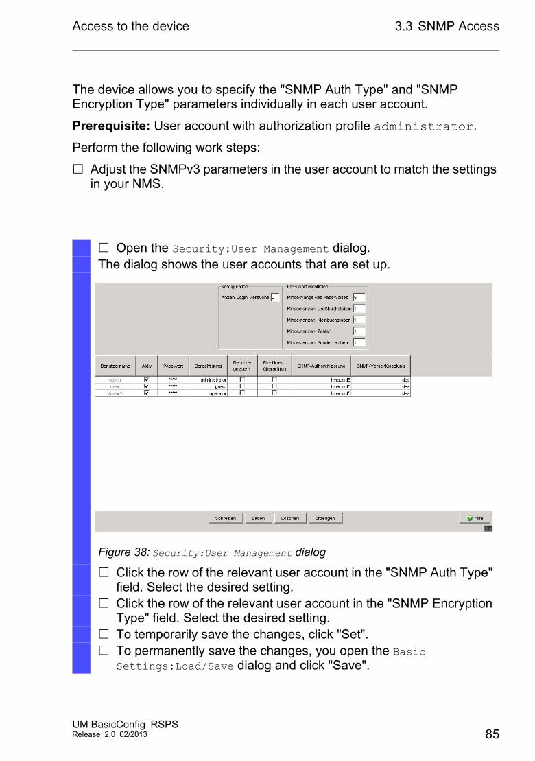
Open the Security:User Management dialog.The dialog shows the user accounts that are set up.
Figure 38: Security:User Management dialog
Click the row of the relevant user account in the "SNMP Auth Type" field. Select the desired setting.
Click the row of the relevant user account in the "SNMP Encryption Type" field. Select the desired setting.
To temporarily save the changes, click "Set". To permanently save the changes, you open the Basic
Settings:Load/Save dialog and click "Save".
UM BasicConfig RSPSRelease 2.0 02/2013 85
Access to the device 3.3 SNMP Access
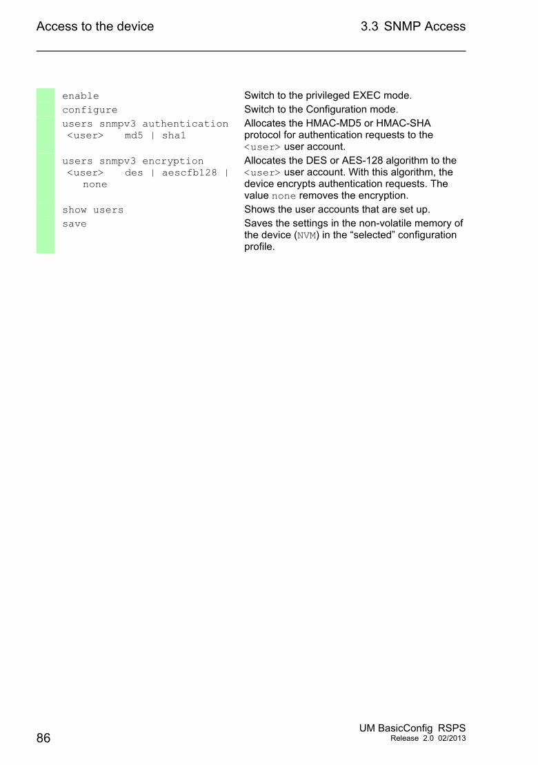
enable Switch to the privileged EXEC mode.configure Switch to the Configuration mode.users snmpv3 authentication <user> md5 | sha1
Allocates the HMAC-MD5 or HMAC-SHA protocol for authentication requests to the <user> user account.
users snmpv3 encryption <user> des | aescfb128 |
none
Allocates the DES or AES-128 algorithm to the <user> user account. With this algorithm, the device encrypts authentication requests. The value none removes the encryption.
show users Shows the user accounts that are set up.save Saves the settings in the non-volatile memory of
the device (NVM) in the “selected” configuration profile.
86UM BasicConfig RSPS
Release 2.0 02/2013
Managing configuration profiles
4 Managing configuration profiles
If you change the settings of the device during operation, the device stores the changes in its memory (RAM). After a reboot the settings are lost.
In order to keep the changes after a reboot, the device offers the possibility of saving additional settings in a configuration profile in the non-volatile memory (NVM). In order to make it possible to quickly switch to other settings, the non-volatile memory offers storage space for multiple configuration profiles.
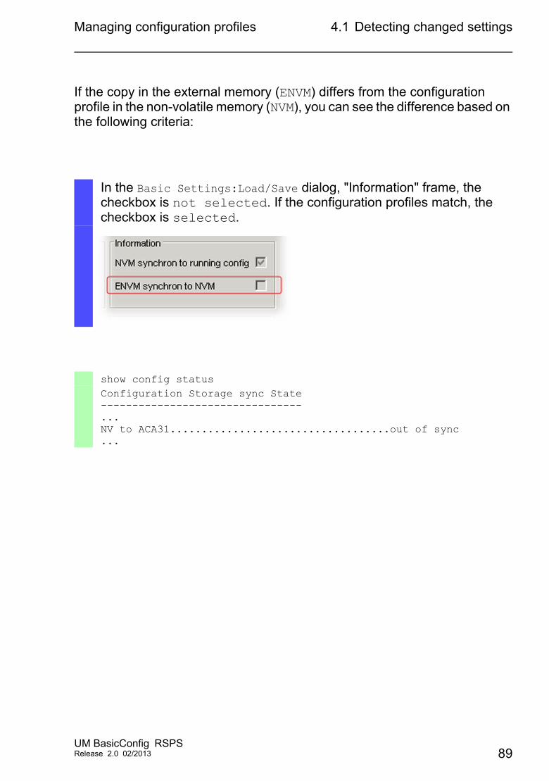
If external memory (ENVM) is connected, the device automatically generates a copy in the external memory when saving a configuration profile. This function can be deactivated.
UM BasicConfig RSPSRelease 2.0 02/2013 87
Managing configuration profiles 4.1 Detecting changed settings
4.1 Detecting changed settings
Changes made to settings during operation are stored by the device in its memory (RAM). The configuration profile in non-volatile memory (NVM) remains unchanged until you explicitly save it. Until then, the configuration profiles in memory and non-volatile memory differ.
This device helps you recognize changed settings. If the configuration profile in the memory (RAM) differs from the "selected" configuration profile in the non-volatile memory (NVM), you can recognize the difference based on the following criteria:
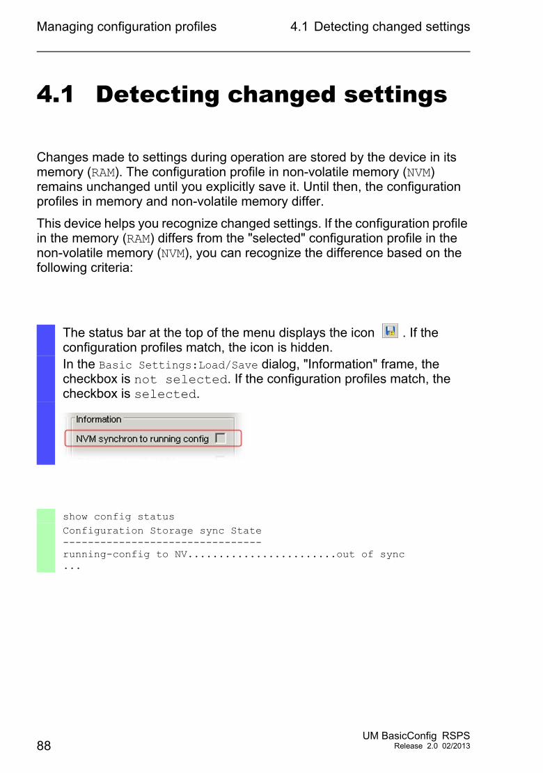
The status bar at the top of the menu displays the icon . If the configuration profiles match, the icon is hidden.In the Basic Settings:Load/Save dialog, "Information" frame, the checkbox is not selected. If the configuration profiles match, the checkbox is selected.
show config statusConfiguration Storage sync State--------------------------------running-config to NV........................out of sync...
88UM BasicConfig RSPS
Release 2.0 02/2013
Managing configuration profiles 4.1 Detecting changed settings
If the copy in the external memory (ENVM) differs from the configuration profile in the non-volatile memory (NVM), you can see the difference based on the following criteria:
In the Basic Settings:Load/Save dialog, "Information" frame, the checkbox is not selected. If the configuration profiles match, the checkbox is selected.
show config statusConfiguration Storage sync State--------------------------------...NV to ACA31...................................out of sync...
UM BasicConfig RSPSRelease 2.0 02/2013 89
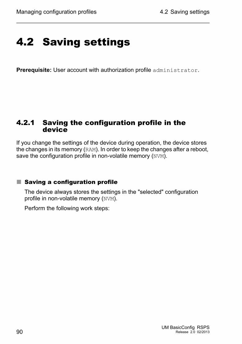
Managing configuration profiles 4.2 Saving settings
4.2 Saving settings
Prerequisite: User account with authorization profile administrator.
4.2.1 Saving the configuration profile in the device
If you change the settings of the device during operation, the device stores the changes in its memory (RAM). In order to keep the changes after a reboot, save the configuration profile in non-volatile memory (NVM).
Saving a configuration profileThe device always stores the settings in the "selected" configuration profile in non-volatile memory (NVM).
Perform the following work steps:
90UM BasicConfig RSPS
Release 2.0 02/2013
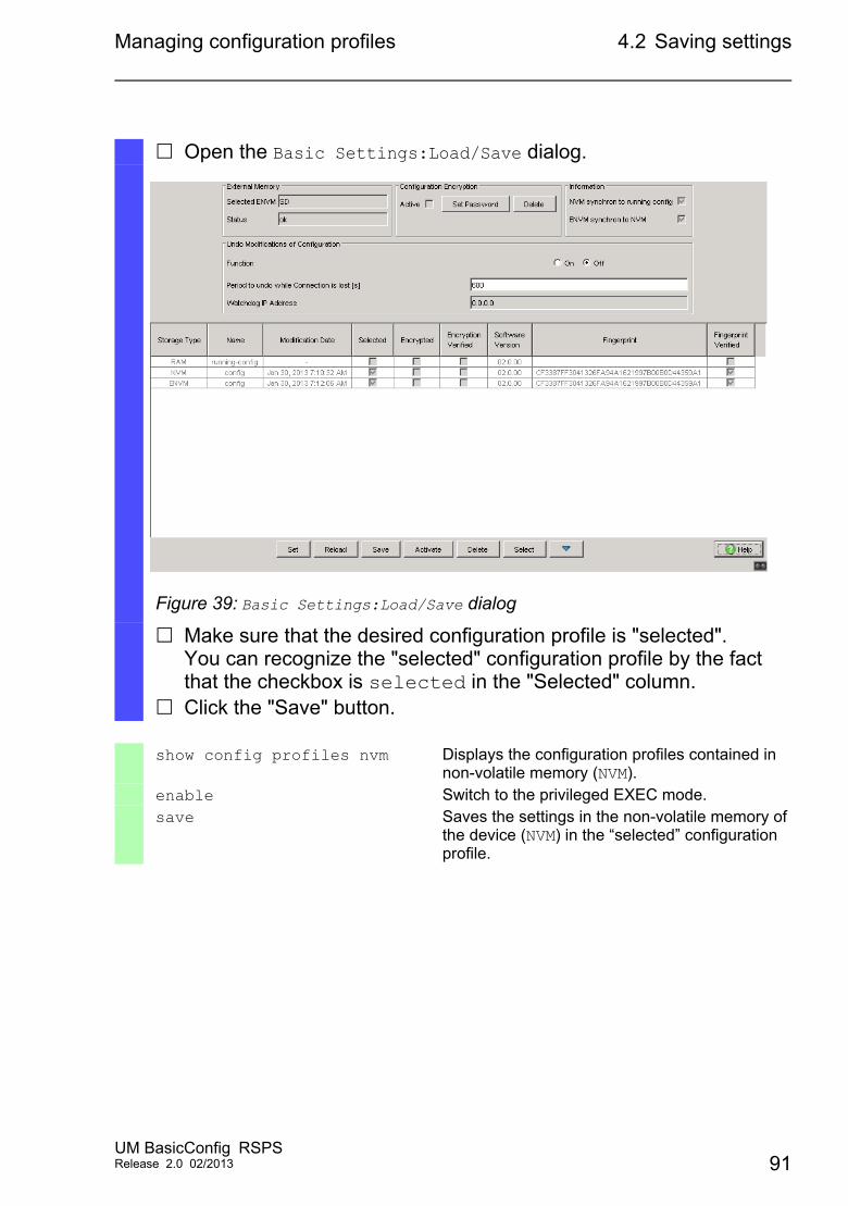
Managing configuration profiles 4.2 Saving settings
Open the Basic Settings:Load/Save dialog.
Figure 39: Basic Settings:Load/Save dialog
Make sure that the desired configuration profile is "selected".You can recognize the "selected" configuration profile by the fact that the checkbox is selected in the "Selected" column.
Click the "Save" button.
show config profiles nvm Displays the configuration profiles contained in non-volatile memory (NVM).
enable Switch to the privileged EXEC mode.save Saves the settings in the non-volatile memory of
the device (NVM) in the “selected” configuration profile.
UM BasicConfig RSPSRelease 2.0 02/2013 91
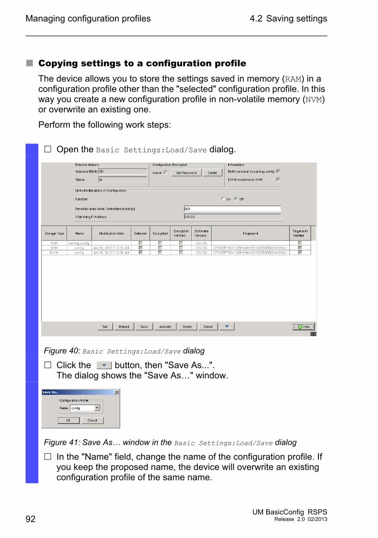
Managing configuration profiles 4.2 Saving settings
Copying settings to a configuration profileThe device allows you to store the settings saved in memory (RAM) in a configuration profile other than the "selected" configuration profile. In this way you create a new configuration profile in non-volatile memory (NVM) or overwrite an existing one.
Perform the following work steps:
Open the Basic Settings:Load/Save dialog.
Figure 40: Basic Settings:Load/Save dialog
Click the button, then "Save As...".The dialog shows the "Save As…" window.
Figure 41: Save As… window in the Basic Settings:Load/Save dialog
In the "Name" field, change the name of the configuration profile. If you keep the proposed name, the device will overwrite an existing configuration profile of the same name.
92UM BasicConfig RSPS
Release 2.0 02/2013
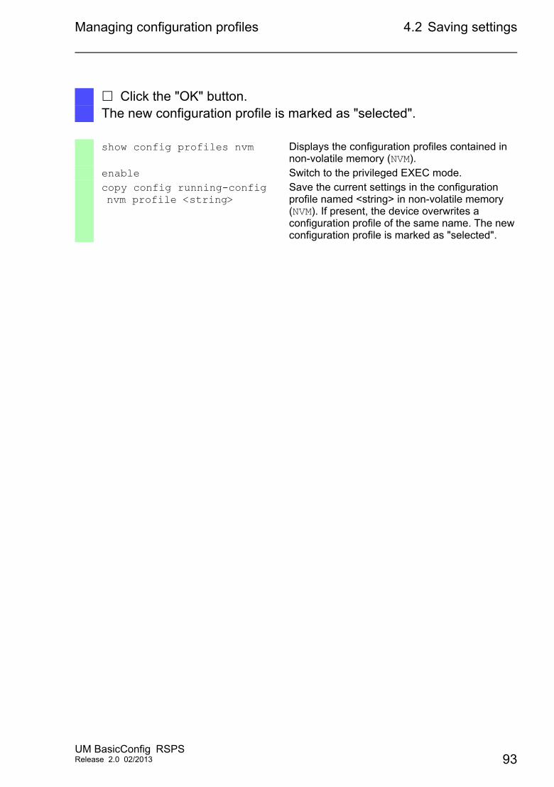
Managing configuration profiles 4.2 Saving settings
Click the "OK" button.The new configuration profile is marked as "selected".
show config profiles nvm Displays the configuration profiles contained in non-volatile memory (NVM).
enable Switch to the privileged EXEC mode.copy config running-config nvm profile <string>
Save the current settings in the configuration profile named <string> in non-volatile memory (NVM). If present, the device overwrites a configuration profile of the same name. The new configuration profile is marked as "selected".
UM BasicConfig RSPSRelease 2.0 02/2013 93
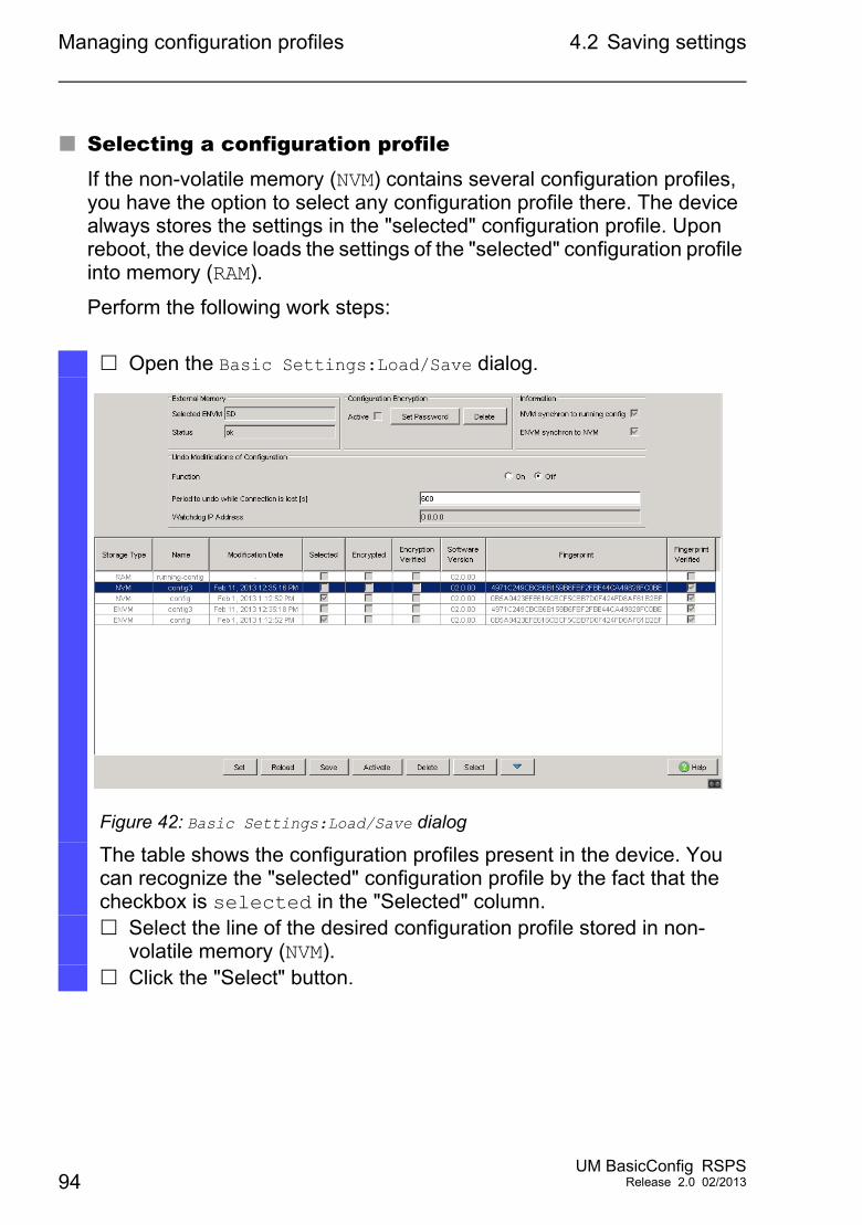
Managing configuration profiles 4.2 Saving settings
Selecting a configuration profileIf the non-volatile memory (NVM) contains several configuration profiles, you have the option to select any configuration profile there. The device always stores the settings in the "selected" configuration profile. Upon reboot, the device loads the settings of the "selected" configuration profile into memory (RAM).
Perform the following work steps:
Open the Basic Settings:Load/Save dialog.
Figure 42: Basic Settings:Load/Save dialog
The table shows the configuration profiles present in the device. You can recognize the "selected" configuration profile by the fact that the checkbox is selected in the "Selected" column. Select the line of the desired configuration profile stored in non-
volatile memory (NVM). Click the "Select" button.
94UM BasicConfig RSPS
Release 2.0 02/2013
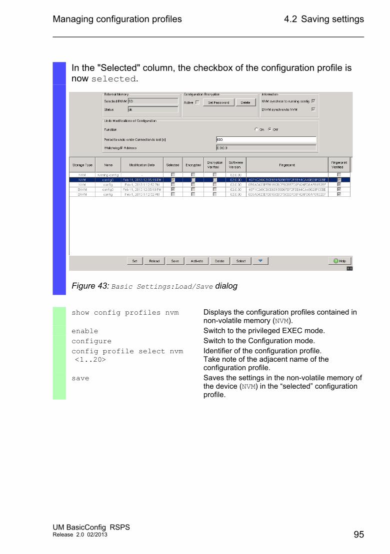
Managing configuration profiles 4.2 Saving settings
In the "Selected" column, the checkbox of the configuration profile is now selected.
Figure 43: Basic Settings:Load/Save dialog
show config profiles nvm Displays the configuration profiles contained in non-volatile memory (NVM).
enable Switch to the privileged EXEC mode.configure Switch to the Configuration mode.config profile select nvm <1..20>
Identifier of the configuration profile.Take note of the adjacent name of the configuration profile.
save Saves the settings in the non-volatile memory of the device (NVM) in the “selected” configuration profile.
UM BasicConfig RSPSRelease 2.0 02/2013 95
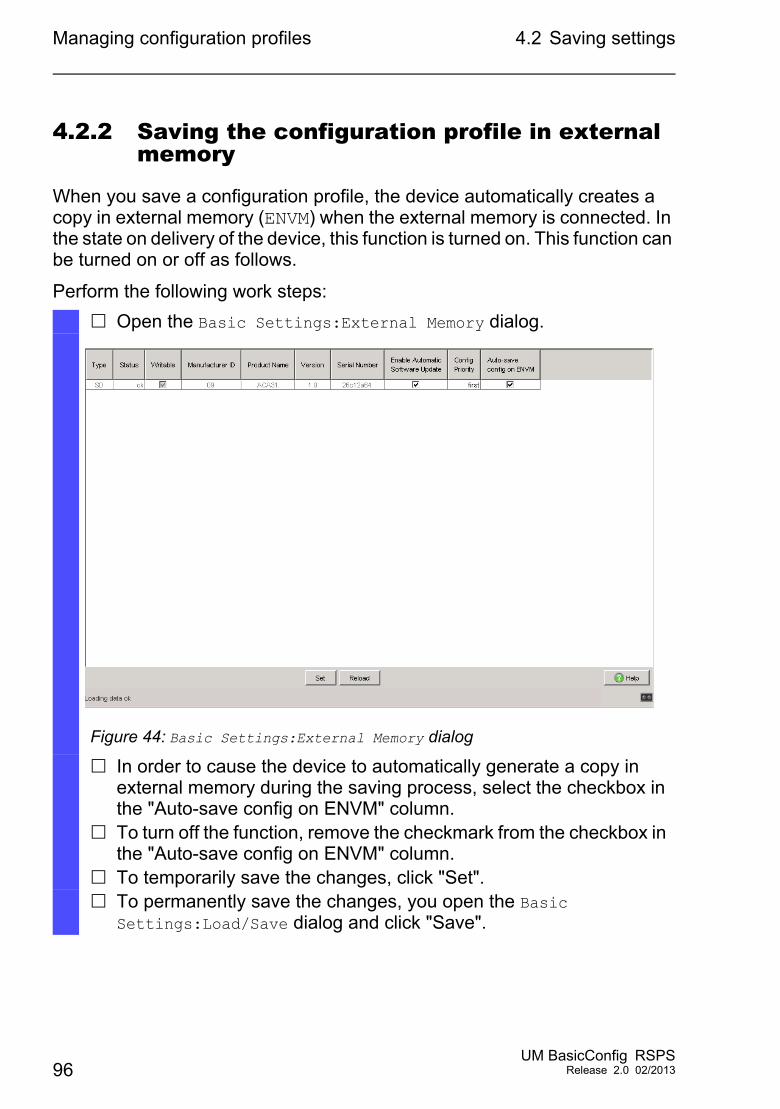
Managing configuration profiles 4.2 Saving settings
4.2.2 Saving the configuration profile in external memory
When you save a configuration profile, the device automatically creates a copy in external memory (ENVM) when the external memory is connected. In the state on delivery of the device, this function is turned on. This function can be turned on or off as follows.
Perform the following work steps:
Open the Basic Settings:External Memory dialog.
Figure 44: Basic Settings:External Memory dialog
In order to cause the device to automatically generate a copy in external memory during the saving process, select the checkbox in the "Auto-save config on ENVM" column.
To turn off the function, remove the checkmark from the checkbox in the "Auto-save config on ENVM" column.
To temporarily save the changes, click "Set". To permanently save the changes, you open the Basic
Settings:Load/Save dialog and click "Save".
96UM BasicConfig RSPS
Release 2.0 02/2013
Managing configuration profiles 4.2 Saving settings
enable Switch to the privileged EXEC mode.configure Switch to the Configuration mode.config envm config-save sd Turn on the function. When you save a
configuration profile, the device creates a copy in external memory ACA31.
no config envm config-save sd Turn off the function. The device does not create a copy in external memory ACA31.
save Saves the settings in the non-volatile memory of the device (NVM) in the “selected” configuration profile.
UM BasicConfig RSPSRelease 2.0 02/2013 97
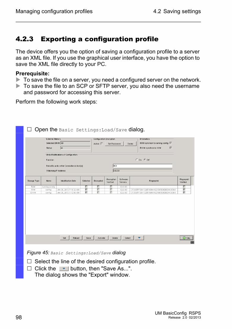
Managing configuration profiles 4.2 Saving settings
4.2.3 Exporting a configuration profile
The device offers you the option of saving a configuration profile to a server as an XML file. If you use the graphical user interface, you have the option to save the XML file directly to your PC.
Prerequisite: To save the file on a server, you need a configured server on the network. To save the file to an SCP or SFTP server, you also need the username
and password for accessing this server.
Perform the following work steps:
Open the Basic Settings:Load/Save dialog.
Figure 45: Basic Settings:Load/Save dialog
Select the line of the desired configuration profile. Click the button, then "Save As...".
The dialog shows the "Export" window.
98UM BasicConfig RSPS
Release 2.0 02/2013
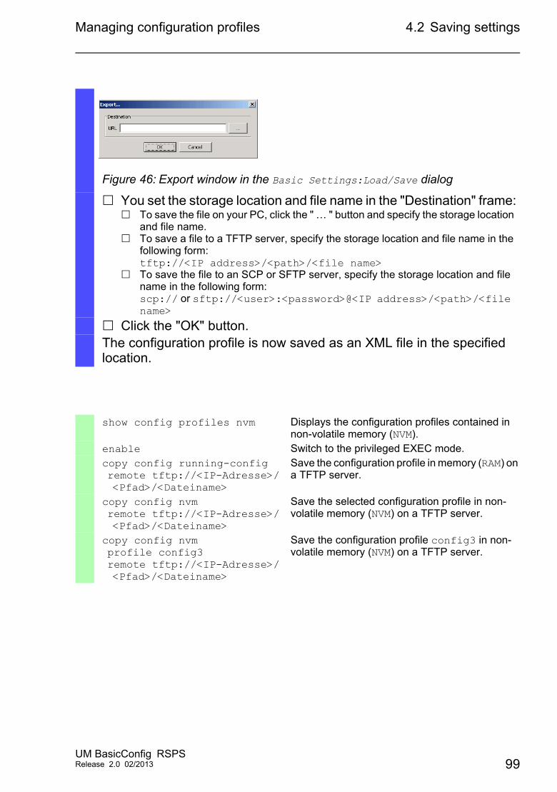
Managing configuration profiles 4.2 Saving settings
Figure 46: Export window in the Basic Settings:Load/Save dialog
You set the storage location and file name in the "Destination" frame: To save the file on your PC, click the " … " button and specify the storage location
and file name. To save a file to a TFTP server, specify the storage location and file name in the
following form:tftp://<IP address>/<path>/<file name>
To save the file to an SCP or SFTP server, specify the storage location and file name in the following form:scp:// or sftp://<user>:<password>@<IP address>/<path>/<file name>
Click the "OK" button.The configuration profile is now saved as an XML file in the specified location.
show config profiles nvm Displays the configuration profiles contained in non-volatile memory (NVM).
enable Switch to the privileged EXEC mode.copy config running-config remote tftp://<IP-Adresse>/ <Pfad>/<Dateiname>
Save the configuration profile in memory (RAM) on a TFTP server.
copy config nvm remote tftp://<IP-Adresse>/ <Pfad>/<Dateiname>
Save the selected configuration profile in non-volatile memory (NVM) on a TFTP server.
copy config nvm profile config3 remote tftp://<IP-Adresse>/ <Pfad>/<Dateiname>
Save the configuration profile config3 in non-volatile memory (NVM) on a TFTP server.
UM BasicConfig RSPSRelease 2.0 02/2013 99
Managing configuration profiles 4.3 Loading settings
4.3 Loading settings
Through loading of settings, the device allows you to quickly switch to other settings if required.
Prerequisite: User account with authorization profile administrator.
4.3.1 Activating a configuration profile
The non-volatile memory of the device can accommodate several configuration profiles. If you activate a configuration profile stored there, you change the settings on the device on the fly without rebooting.
Perform the following work steps:
100UM BasicConfig RSPS
Release 2.0 02/2013
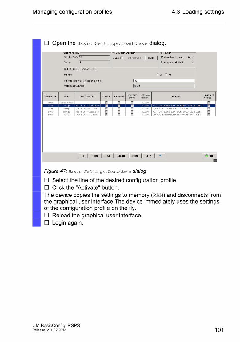
Managing configuration profiles 4.3 Loading settings
Open the Basic Settings:Load/Save dialog.
Figure 47: Basic Settings:Load/Save dialog
Select the line of the desired configuration profile. Click the "Activate" button.The device copies the settings to memory (RAM) and disconnects from the graphical user interface.The device immediately uses the settings of the configuration profile on the fly. Reload the graphical user interface. Login again.
UM BasicConfig RSPSRelease 2.0 02/2013 101
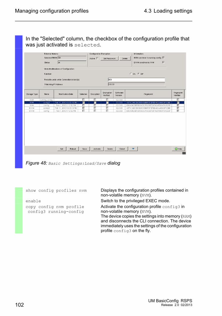
Managing configuration profiles 4.3 Loading settings
In the "Selected" column, the checkbox of the configuration profile that was just activated is selected.
Figure 48: Basic Settings:Load/Save dialog
show config profiles nvm Displays the configuration profiles contained in non-volatile memory (NVM).
enable Switch to the privileged EXEC mode.copy config nvm profile config3 running-config
Activate the configuration profile config3 in non-volatile memory (NVM).The device copies the settings into memory (RAM) and disconnects the CLI connection. The device immediately uses the settings of the configuration profile config3 on the fly.
102UM BasicConfig RSPS
Release 2.0 02/2013
Managing configuration profiles 4.3 Loading settings
4.3.2 Loading the configuration profile from the external memory
Upon reboot, the device automatically loads a configuration profile from the external memory (ENVM) if the external memory is connected. The device offers you the option of saving these settings in a configuration profile in non-volatile memory (NVM).
If the external memory contains the configuration profile of an identical device, this allows you to transfer the settings from one device to another.
Perform the following work steps:
Make sure that the device loads a configuration profile from the external memory (ENVM) upon reboot.
In the state on delivery of the device, this function is turned on. If the function is turned off, turn it on again as follows:
UM BasicConfig RSPSRelease 2.0 02/2013 103
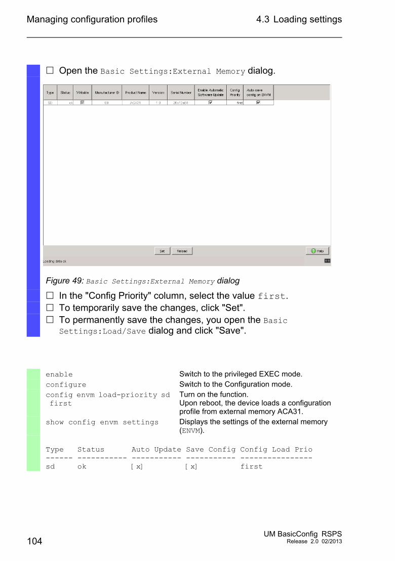
Managing configuration profiles 4.3 Loading settings
Open the Basic Settings:External Memory dialog.
Figure 49: Basic Settings:External Memory dialog
In the "Config Priority" column, select the value first. To temporarily save the changes, click "Set". To permanently save the changes, you open the Basic
Settings:Load/Save dialog and click "Save".
enable Switch to the privileged EXEC mode.configure Switch to the Configuration mode.config envm load-priority sd first
Turn on the function.Upon reboot, the device loads a configuration profile from external memory ACA31.
show config envm settings Displays the settings of the external memory (ENVM).
Type Status Auto Update Save Config Config Load Prio------ ----------- ----------- ----------- ----------------sd ok [x] [x] first
104UM BasicConfig RSPS
Release 2.0 02/2013
Managing configuration profiles 4.3 Loading settings
Save the settings of the device in a configuration profile in non-volatile memory (NVM).See “Saving the configuration profile in the device” on page 90.
With CLI, the device offers the option of copying the settings from the external memory (ENVM) directly into non-volatile memory (NVM).
show config profiles nvm Displays the configuration profiles contained in non-volatile memory (NVM).
enable Switch to the privileged EXEC mode.copy config envm profile config3 nvm
Copy the configuration profile config3 from the external memory (ENVM) to the non-volatile memory (NVM).
UM BasicConfig RSPSRelease 2.0 02/2013 105
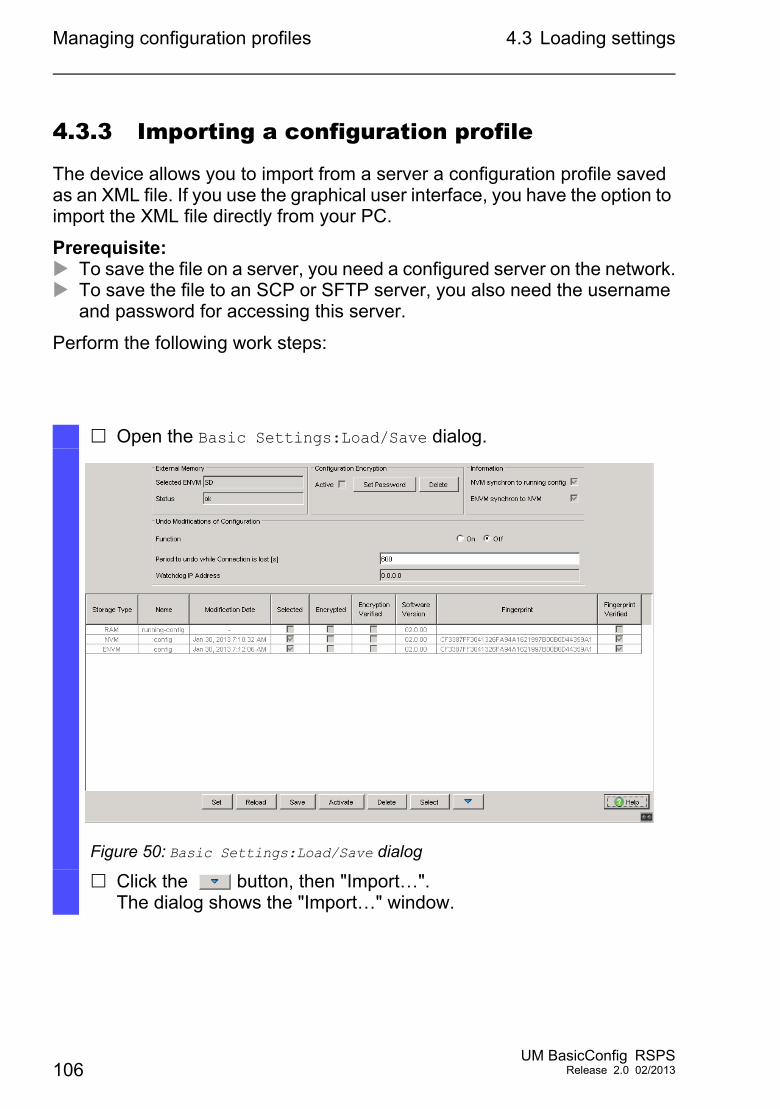
Managing configuration profiles 4.3 Loading settings
4.3.3 Importing a configuration profile
The device allows you to import from a server a configuration profile saved as an XML file. If you use the graphical user interface, you have the option to import the XML file directly from your PC.
Prerequisite: To save the file on a server, you need a configured server on the network. To save the file to an SCP or SFTP server, you also need the username
and password for accessing this server.
Perform the following work steps:
Open the Basic Settings:Load/Save dialog.
Figure 50: Basic Settings:Load/Save dialog
Click the button, then "Import…".The dialog shows the "Import…" window.
106UM BasicConfig RSPS
Release 2.0 02/2013
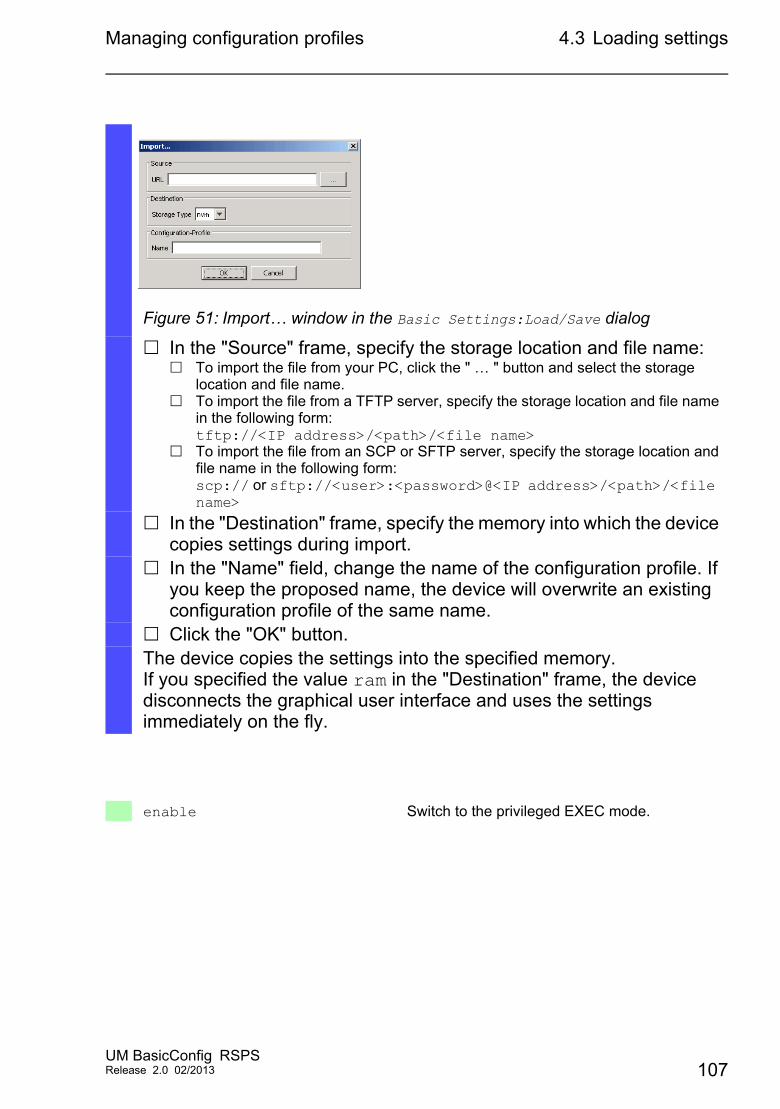
Managing configuration profiles 4.3 Loading settings
Figure 51: Import… window in the Basic Settings:Load/Save dialog
In the "Source" frame, specify the storage location and file name: To import the file from your PC, click the " … " button and select the storage
location and file name. To import the file from a TFTP server, specify the storage location and file name
in the following form:tftp://<IP address>/<path>/<file name>
To import the file from an SCP or SFTP server, specify the storage location and file name in the following form:scp:// or sftp://<user>:<password>@<IP address>/<path>/<file name>
In the "Destination" frame, specify the memory into which the device copies settings during import.
In the "Name" field, change the name of the configuration profile. If you keep the proposed name, the device will overwrite an existing configuration profile of the same name.
Click the "OK" button.The device copies the settings into the specified memory.If you specified the value ram in the "Destination" frame, the device disconnects the graphical user interface and uses the settings immediately on the fly.
enable Switch to the privileged EXEC mode.
UM BasicConfig RSPSRelease 2.0 02/2013 107
Managing configuration profiles 4.3 Loading settings
copy config remote tftp://<IP-Adresse>/ <Pfad>/<Dateiname> running-config
Import a configuration profile from a TFTP server into memory (RAM).The device copies the settings into memory (RAM) and disconnects the CLI connection. The device immediately uses these settings on the fly.
copy config remote sftp://<Benutzername>:<Passwort>@<IP-Adresse>/<pfad>/ <Dateiname> running-config
Import a configuration profile from an SFTP server to memory (RAM).The device copies the settings into memory (RAM) and disconnects the CLI connection. The device immediately uses these settings on the fly.
copy config remote tftp://<IP-Adresse>/ <Pfad>/<Dateiname> nvm profile config3
Import a configuration profile from a TFTP server, save in non-volatile memory (NVM) as configuration profile config3.
108UM BasicConfig RSPS
Release 2.0 02/2013
Managing configuration profiles 4.4 Resetting the device to the factorydefaults
4.4 Resetting the device to the factory defaults
If you reset the settings in the device to the factory defaults, the device deletes the configuration profile in the memory (RAM) and in the non-volatile memory (NVM).
If external memory is connected, the device also deletes the configuration profiles saved in the external memory (ENVM).
The device then reboots and loads the factory settings.
4.4.1 With the graphical user interface or CLI
Prerequisite: User account with authorization profile administrator.
Perform the following work steps:
UM BasicConfig RSPSRelease 2.0 02/2013 109
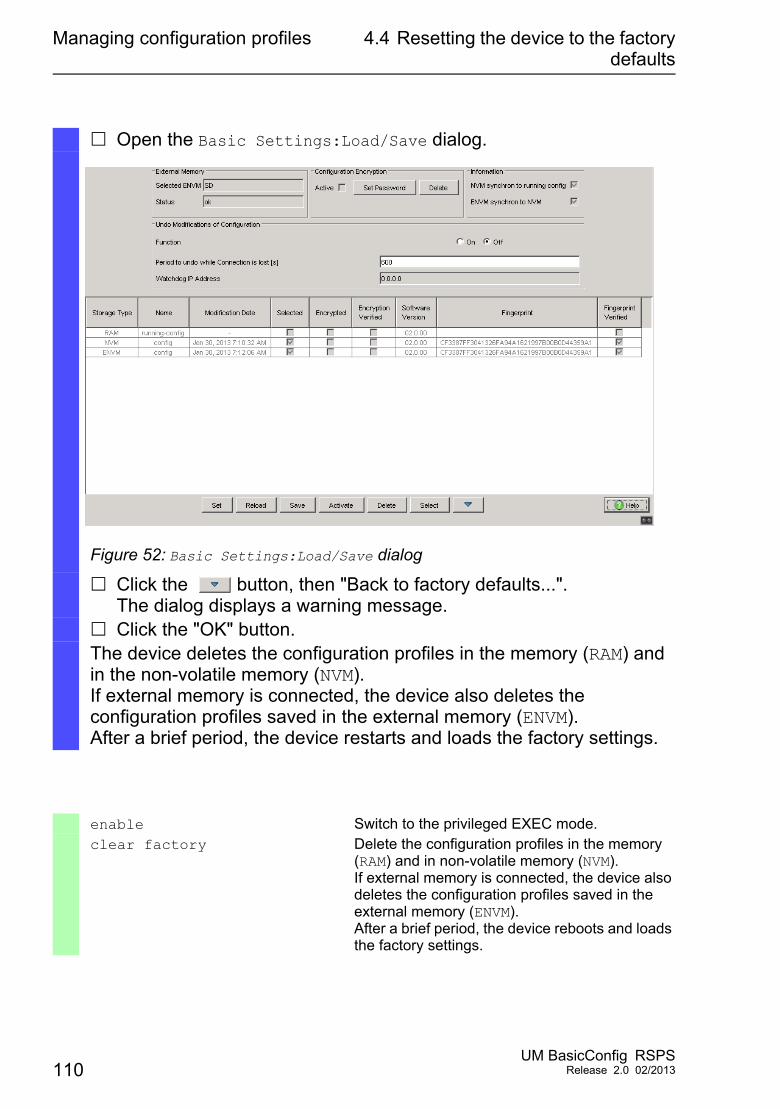
Managing configuration profiles 4.4 Resetting the device to the factorydefaults
Open the Basic Settings:Load/Save dialog.
Figure 52: Basic Settings:Load/Save dialog
Click the button, then "Back to factory defaults...".The dialog displays a warning message.
Click the "OK" button.The device deletes the configuration profiles in the memory (RAM) and in the non-volatile memory (NVM).If external memory is connected, the device also deletes the configuration profiles saved in the external memory (ENVM).After a brief period, the device restarts and loads the factory settings.
enable Switch to the privileged EXEC mode.clear factory Delete the configuration profiles in the memory
(RAM) and in non-volatile memory (NVM).If external memory is connected, the device also deletes the configuration profiles saved in the external memory (ENVM).After a brief period, the device reboots and loads the factory settings.
110UM BasicConfig RSPS
Release 2.0 02/2013
Managing configuration profiles 4.4 Resetting the device to the factorydefaults
4.4.2 In the System Monitor
Prerequisite: Your PC is connected via terminal cable with the V.24 connection of the device.
Perform the following work steps:
Restart the device.
To switch to the System Monitor, press 1 within 3 seconds when prompted during reboot.The device loads the System Monitor.
To switch from the main menu to the Manage configurations menu, press 4.
To execute the Clear configs and boot params command, press 1.
To load the factory settings, press the Enter key.The device deletes the configuration profiles in the memory (RAM) and in the non-volatile memory (NVM).
If external memory is connected, the device also deletes the configuration profiles saved in the external memory (ENVM).
To switch to the main menu, press q.
To reboot the device with factory settings, press q.
UM BasicConfig RSPSRelease 2.0 02/2013 111

Managing configuration profiles 4.4 Resetting the device to the factorydefaults
112UM BasicConfig RSPS
Release 2.0 02/2013
Synchronizing the System Time in the Network
5 Synchronizing the System Time in the Network
Many applications rely on a time that is as correct as possible. The necessary accuracy, and thus the allowable deviation from the actual time, depends on the application area.
Examples of application areas include: Log entries Time stamping of production data Process control
The device offers the following options for synchronizing the time on the network:
The Simple Network Time Protocol (SNTP) is a simple solution for low accuracy requirements. Under ideal conditions, SNTP achieves an accuracy in the millisecond range. The accuracy depends on the signal delay.
IEEE 1588 with the Precision Time Protocol (PTP) achieves accuracies on the order of fractions of microseconds. This method is suitable even for demanding applications up to and including process control.
PTP is always the better choice if the involved devices support this protocol. PTP is more accurate, has advanced methods of error correction, and causes a low network load. The implementation of PTP is comparatively easy.
Note: According to the PTP and SNTP standards, both protocols function in parallel in the same network. However, since both protocols influence the system time of the device, situations may occur in which the two protocols conflict with each other.
UM BasicConfig RSPSRelease 2.0 02/2013 113
Synchronizing the System Time in the Network
5.1 Basic settings
5.1 Basic settings
In the Time:Basic Settings dialog, you define general settings for the time.
5.1.1 Setting the time
If no reference time source is available to you, you have the option to set the time in the device.
After a cold start or reboot, if no real-time clock is available or if the real-time clock contains an invalid time, the device initializes its clock with January 1, 00:00h. After the power supply is switched off, the device buffers the settings of the real-time clock up to 24 hours.Alternatively, you configure the settings in the device so that it automatically obtains the current time from a PTP clock or from an SNTP server.
114UM BasicConfig RSPS
Release 2.0 02/2013
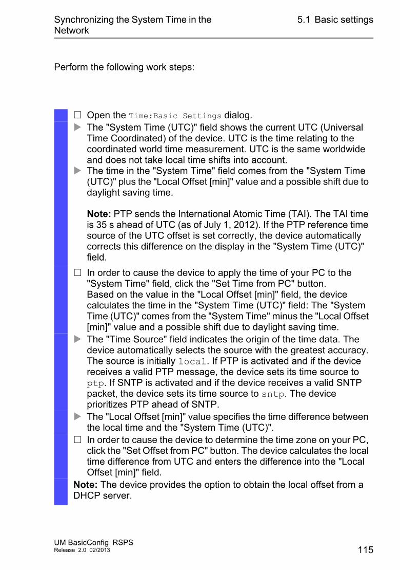
Synchronizing the System Time in the Network
5.1 Basic settings
Perform the following work steps:
Open the Time:Basic Settings dialog. The "System Time (UTC)" field shows the current UTC (Universal
Time Coordinated) of the device. UTC is the time relating to the coordinated world time measurement. UTC is the same worldwide and does not take local time shifts into account.
The time in the "System Time" field comes from the "System Time (UTC)" plus the "Local Offset [min]" value and a possible shift due to daylight saving time.
Note: PTP sends the International Atomic Time (TAI). The TAI time is 35 s ahead of UTC (as of July 1, 2012). If the PTP reference time source of the UTC offset is set correctly, the device automatically corrects this difference on the display in the "System Time (UTC)" field.
In order to cause the device to apply the time of your PC to the "System Time" field, click the "Set Time from PC" button.Based on the value in the "Local Offset [min]" field, the device calculates the time in the "System Time (UTC)" field: The "System Time (UTC)" comes from the "System Time" minus the "Local Offset [min]" value and a possible shift due to daylight saving time.
The "Time Source" field indicates the origin of the time data. The device automatically selects the source with the greatest accuracy.The source is initially local. If PTP is activated and if the device receives a valid PTP message, the device sets its time source to ptp. If SNTP is activated and if the device receives a valid SNTP packet, the device sets its time source to sntp. The device prioritizes PTP ahead of SNTP.
The "Local Offset [min]" value specifies the time difference between the local time and the "System Time (UTC)".
In order to cause the device to determine the time zone on your PC, click the "Set Offset from PC" button. The device calculates the local time difference from UTC and enters the difference into the "Local Offset [min]" field.
Note: The device provides the option to obtain the local offset from a DHCP server.
UM BasicConfig RSPSRelease 2.0 02/2013 115
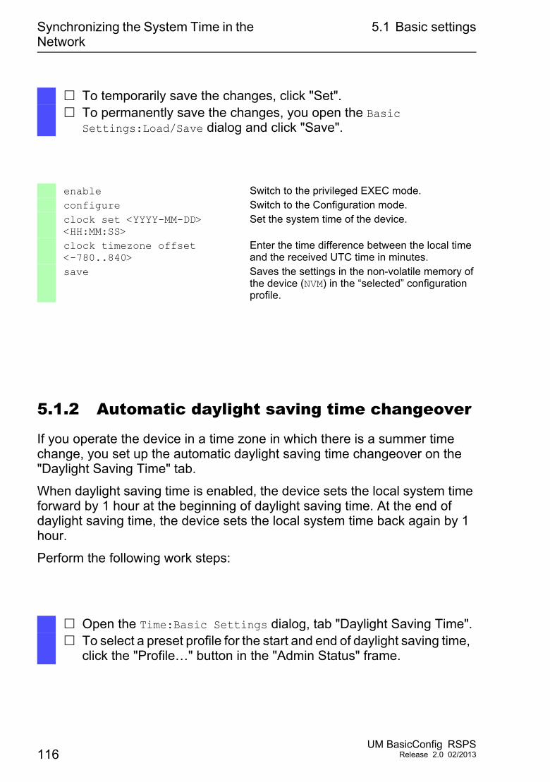
Synchronizing the System Time in the Network
5.1 Basic settings
5.1.2 Automatic daylight saving time changeover
If you operate the device in a time zone in which there is a summer time change, you set up the automatic daylight saving time changeover on the "Daylight Saving Time" tab.
When daylight saving time is enabled, the device sets the local system time forward by 1 hour at the beginning of daylight saving time. At the end of daylight saving time, the device sets the local system time back again by 1 hour.
Perform the following work steps:
To temporarily save the changes, click "Set". To permanently save the changes, you open the Basic
Settings:Load/Save dialog and click "Save".
enable Switch to the privileged EXEC mode.configure Switch to the Configuration mode.clock set <YYYY-MM-DD> <HH:MM:SS>
Set the system time of the device.
clock timezone offset <-780..840>
Enter the time difference between the local time and the received UTC time in minutes.
save Saves the settings in the non-volatile memory of the device (NVM) in the “selected” configuration profile.
Open the Time:Basic Settings dialog, tab "Daylight Saving Time". To select a preset profile for the start and end of daylight saving time,
click the "Profile…" button in the "Admin Status" frame.
116UM BasicConfig RSPS
Release 2.0 02/2013
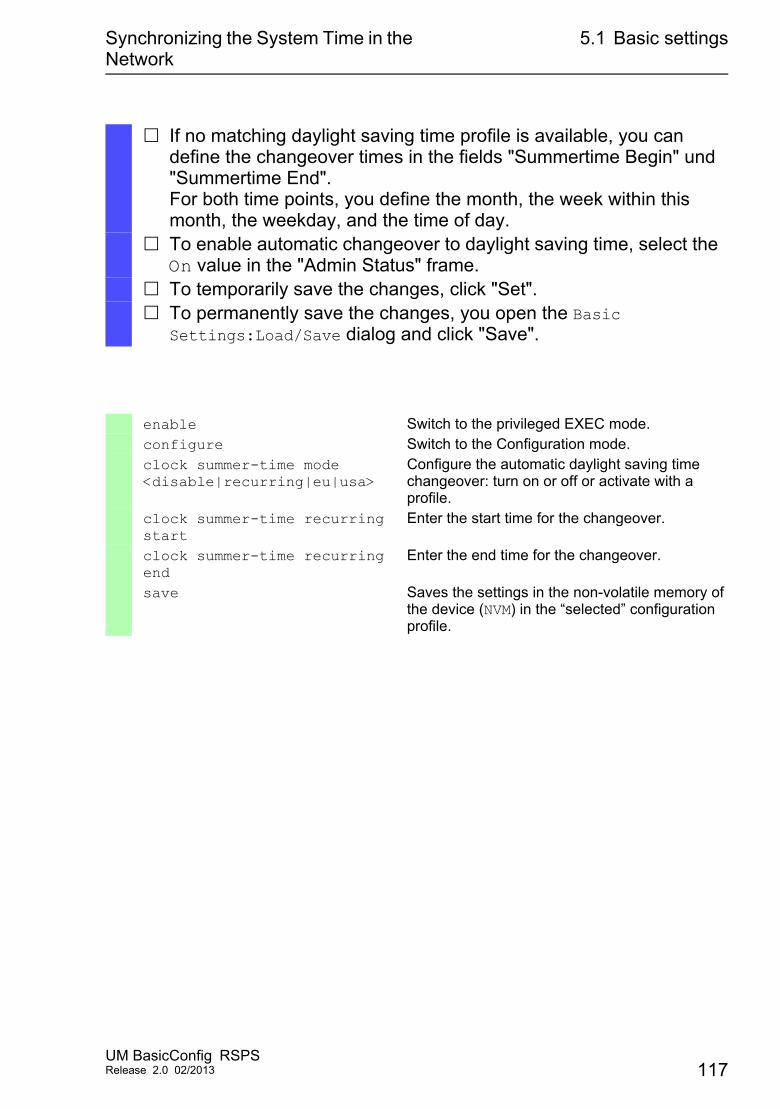
Synchronizing the System Time in the Network
5.1 Basic settings
If no matching daylight saving time profile is available, you can define the changeover times in the fields "Summertime Begin" und "Summertime End".For both time points, you define the month, the week within this month, the weekday, and the time of day.
To enable automatic changeover to daylight saving time, select the On value in the "Admin Status" frame.
To temporarily save the changes, click "Set". To permanently save the changes, you open the Basic
Settings:Load/Save dialog and click "Save".
enable Switch to the privileged EXEC mode.configure Switch to the Configuration mode.clock summer-time mode <disable|recurring|eu|usa>
Configure the automatic daylight saving time changeover: turn on or off or activate with a profile.
clock summer-time recurring start
Enter the start time for the changeover.
clock summer-time recurring end
Enter the end time for the changeover.
save Saves the settings in the non-volatile memory of the device (NVM) in the “selected” configuration profile.
UM BasicConfig RSPSRelease 2.0 02/2013 117
Synchronizing the System Time in the Network
5.2 SNTP
5.2 SNTP
The Simple Network Time Protocol (SNTP) allows you to synchronize the system time in your network. The device supports the SNTP client and the SNTP server function.
The SNTP server makes the UTC (Universal Time Coordinated) available. UTC is the time relating to the coordinated world time measurement. The UTC is the same worldwide and ignores local time shifts.
SNTP is a simplified version of NTP (Network Time Protocol). The data packets are identical with SNTP and NTP. Accordingly, both NTP and SNTP servers serve as a time source for SNTP clients.
Note: Statements in this chapter relating to external SNTP servers also apply to NTP servers.
SNTP knows the following operation modes for the transmission of time:
Unicast: In unicast operation mode, an SNTP client sends requests to an SNTP server and expects a response from this server.
Broadcast: In broadcast operation mode, an SNTP server sends SNTP messages to the network in defined intervals. SNTP clients receive these SNTP messages and evaluate them.
IP destination address Send SNTP packets to0.0.0.0 Nobody224.0.1.1 Multicast address for SNTP messages255.255.255.255 Broadcast address
Table 6: Target address classes for broadcast operation mode
118UM BasicConfig RSPS
Release 2.0 02/2013
Synchronizing the System Time in the Network
5.2 SNTP
Note: An SNTP server in broadcast operation mode also responds to direct requests via unicast from SNTP clients. In contrast, SNTP clients work in either unicast or broadcast operation mode.
UM BasicConfig RSPSRelease 2.0 02/2013 119
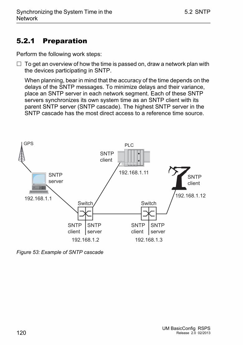
Synchronizing the System Time in the Network
5.2 SNTP
5.2.1 Preparation
Perform the following work steps:
To get an overview of how the time is passed on, draw a network plan with the devices participating in SNTP.
When planning, bear in mind that the accuracy of the time depends on the delays of the SNTP messages. To minimize delays and their variance, place an SNTP server in each network segment. Each of these SNTP servers synchronizes its own system time as an SNTP client with its parent SNTP server (SNTP cascade). The highest SNTP server in the SNTP cascade has the most direct access to a reference time source.
Figure 53: Example of SNTP cascade
GPS
Switch
192.168.1.2
192.168.1.1
192.168.1.11
192.168.1.12
SNTPserver
SNTPclient
SNTPserver
SNTPclient
Switch
192.168.1.3
SNTPserver
SNTPclient
PLC
SNTPclient
120UM BasicConfig RSPS
Release 2.0 02/2013
Synchronizing the System Time in the Network
5.2 SNTP
Note: For precise time distribution, between SNTP servers and SNTP clients you preferably use network components (routers and switches) that forward the SNTP packets with a low and uniform transmission time (latency).
An SNTP client sends its requests to up to 4 configured SNTP servers. If there is no response from the 1st SNTP server, the SNTP client sends its requests to the 2nd SNTP server. If this request is also unsuccessful, it sends the request to the 3rd and finally the 4th SNTP server. If none of these SNTP servers responds, the SNTP client loses its synchronization. The SNTP client periodically sends requests to each SNTP server until a server delivers a valid time.
Note: The device provides the option of obtaining a list of SNTP server IP addresses from a DHCP server.
If no reference time source is available to you, determine a device with an SNTP server as a reference time source. Adjust its system time at regular intervals.
5.2.2 Defining settings of the SNTP client
As an SNTP client, the device obtains the time information from SNTP or NTP servers and synchronizes its system clock accordingly.
Perform the following work steps:
UM BasicConfig RSPSRelease 2.0 02/2013 121
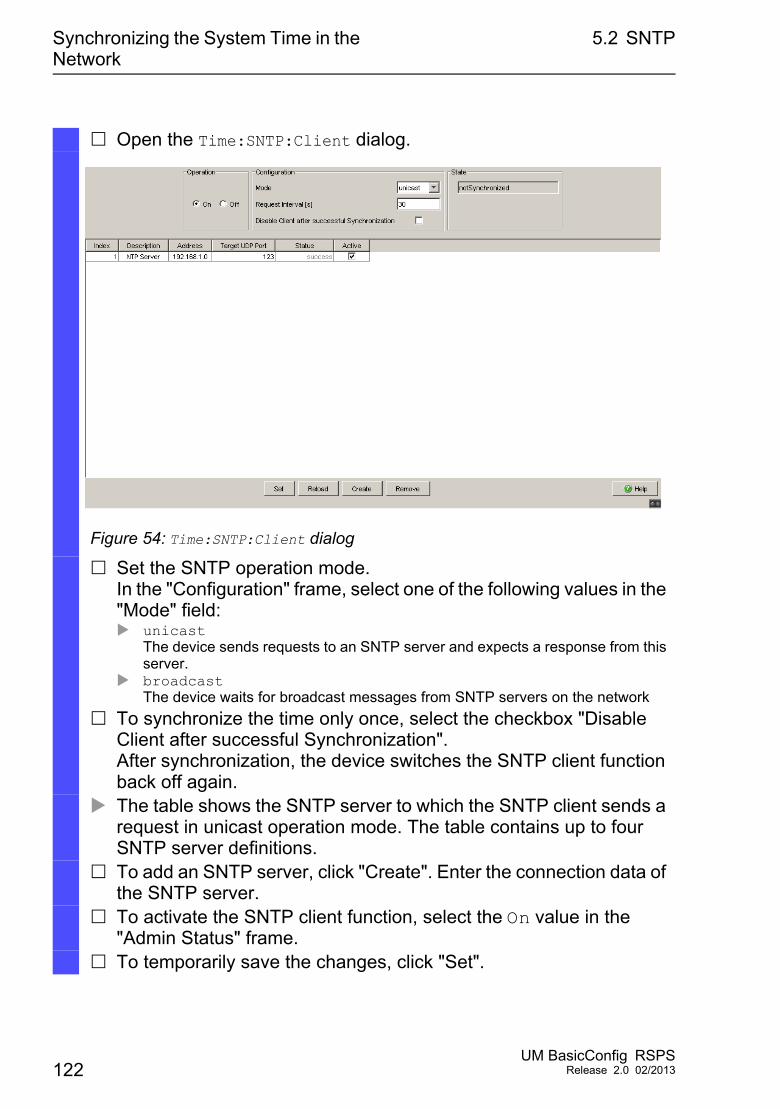
Synchronizing the System Time in the Network
5.2 SNTP
Open the Time:SNTP:Client dialog.
Figure 54: Time:SNTP:Client dialog
Set the SNTP operation mode.In the "Configuration" frame, select one of the following values in the "Mode" field: unicast
The device sends requests to an SNTP server and expects a response from this server.
broadcastThe device waits for broadcast messages from SNTP servers on the network
To synchronize the time only once, select the checkbox "Disable Client after successful Synchronization".After synchronization, the device switches the SNTP client function back off again.
The table shows the SNTP server to which the SNTP client sends a request in unicast operation mode. The table contains up to four SNTP server definitions.
To add an SNTP server, click "Create". Enter the connection data of the SNTP server.
To activate the SNTP client function, select the On value in the "Admin Status" frame.
To temporarily save the changes, click "Set".
122UM BasicConfig RSPS
Release 2.0 02/2013
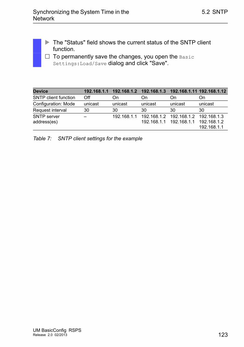
Synchronizing the System Time in the Network
5.2 SNTP
The "Status" field shows the current status of the SNTP client function.
To permanently save the changes, you open the Basic Settings:Load/Save dialog and click "Save".
Device 192.168.1.1 192.168.1.2 192.168.1.3 192.168.1.11 192.168.1.12SNTP client function Off On On On OnConfiguration: Mode unicast unicast unicast unicast unicastRequest interval 30 30 30 30 30SNTP server address(es)
– 192.168.1.1 192.168.1.2192.168.1.1
192.168.1.2192.168.1.1
192.168.1.3192.168.1.2192.168.1.1
Table 7: SNTP client settings for the example
UM BasicConfig RSPSRelease 2.0 02/2013 123
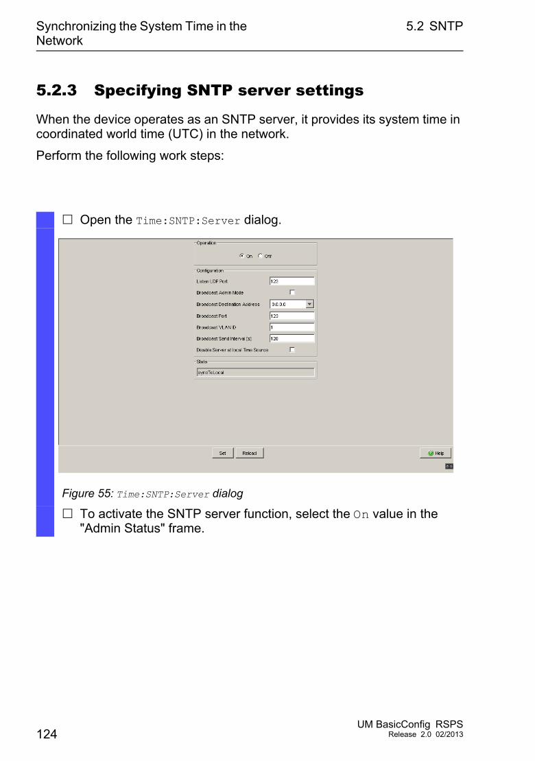
Synchronizing the System Time in the Network
5.2 SNTP
5.2.3 Specifying SNTP server settings
When the device operates as an SNTP server, it provides its system time in coordinated world time (UTC) in the network.
Perform the following work steps:
Open the Time:SNTP:Server dialog.
Figure 55: Time:SNTP:Server dialog
To activate the SNTP server function, select the On value in the "Admin Status" frame.
124UM BasicConfig RSPS
Release 2.0 02/2013
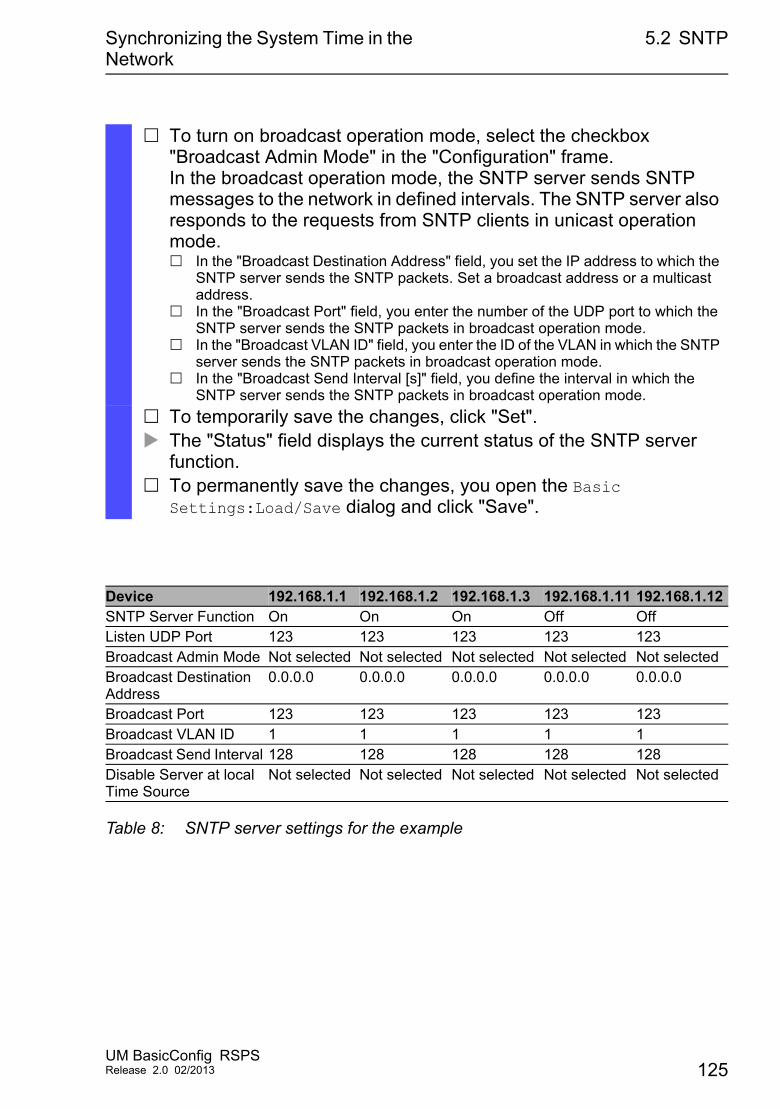
Synchronizing the System Time in the Network
5.2 SNTP
To turn on broadcast operation mode, select the checkbox "Broadcast Admin Mode" in the "Configuration" frame.In the broadcast operation mode, the SNTP server sends SNTP messages to the network in defined intervals. The SNTP server also responds to the requests from SNTP clients in unicast operation mode. In the "Broadcast Destination Address" field, you set the IP address to which the
SNTP server sends the SNTP packets. Set a broadcast address or a multicast address.
In the "Broadcast Port" field, you enter the number of the UDP port to which the SNTP server sends the SNTP packets in broadcast operation mode.
In the "Broadcast VLAN ID" field, you enter the ID of the VLAN in which the SNTP server sends the SNTP packets in broadcast operation mode.
In the "Broadcast Send Interval [s]" field, you define the interval in which the SNTP server sends the SNTP packets in broadcast operation mode.
To temporarily save the changes, click "Set". The "Status" field displays the current status of the SNTP server
function. To permanently save the changes, you open the Basic
Settings:Load/Save dialog and click "Save".
Device 192.168.1.1 192.168.1.2 192.168.1.3 192.168.1.11 192.168.1.12SNTP Server Function On On On Off OffListen UDP Port 123 123 123 123 123Broadcast Admin Mode Not selected Not selected Not selected Not selected Not selectedBroadcast Destination Address
0.0.0.0 0.0.0.0 0.0.0.0 0.0.0.0 0.0.0.0
Broadcast Port 123 123 123 123 123Broadcast VLAN ID 1 1 1 1 1Broadcast Send Interval 128 128 128 128 128Disable Server at local Time Source
Not selected Not selected Not selected Not selected Not selected
Table 8: SNTP server settings for the example
UM BasicConfig RSPSRelease 2.0 02/2013 125
Synchronizing the System Time in the Network
5.3 PTP
5.3 PTP
In order for LAN-controlled applications to work without latency, precise time management is required. With PTP (Precision Time Protocol), IEEE 1588 describes a method that enables precise synchronization of clocks in the network.
PTP enables synchronization with an accuracy of a few 100 ns. PTP uses multicast for the synchronization messages, which keeps the network load low.
5.3.1 Types of clocks
PTP defines the roles of “master” and “slave” for the clocks in the network: A master clock (reference time source) distributes its time. A slave clock synchronizes itself with the timing signal received from the
master clock.
126UM BasicConfig RSPS
Release 2.0 02/2013
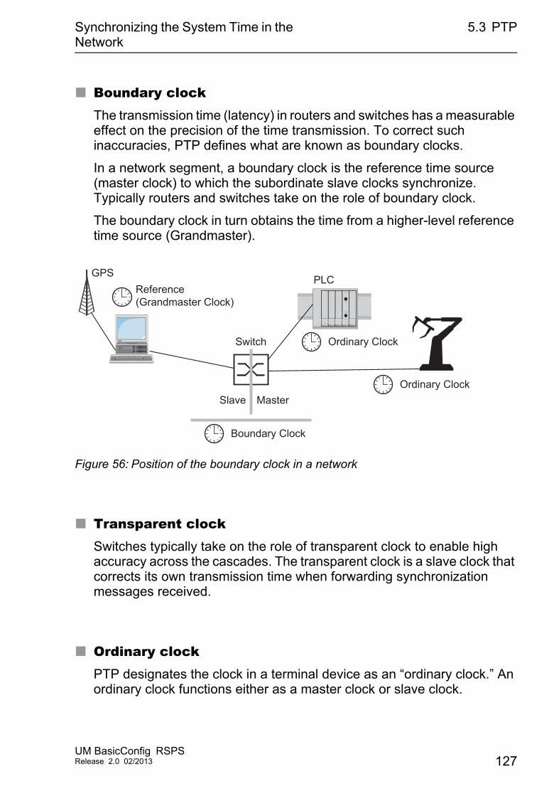
Synchronizing the System Time in the Network
5.3 PTP
Boundary clockThe transmission time (latency) in routers and switches has a measurable effect on the precision of the time transmission. To correct such inaccuracies, PTP defines what are known as boundary clocks.
In a network segment, a boundary clock is the reference time source (master clock) to which the subordinate slave clocks synchronize. Typically routers and switches take on the role of boundary clock.
The boundary clock in turn obtains the time from a higher-level reference time source (Grandmaster).
Figure 56: Position of the boundary clock in a network
Transparent clockSwitches typically take on the role of transparent clock to enable high accuracy across the cascades. The transparent clock is a slave clock that corrects its own transmission time when forwarding synchronization messages received.
Ordinary clockPTP designates the clock in a terminal device as an “ordinary clock.” An ordinary clock functions either as a master clock or slave clock.
GPSReference(Grandmaster Clock)
MasterSlave
Boundary Clock
Ordinary Clock
Ordinary Clock
Switch
PLC
UM BasicConfig RSPSRelease 2.0 02/2013 127
Synchronizing the System Time in the Network
5.3 PTP
5.3.2 Best Master Clock algorithm
The devices participating in PTP designate a device in the network as a reference time source (Grandmaster). Here the “Best Master Clock” algorithm is used, which determines the accuracy of the clocks available in the network.
The “Best Master Clock” algorithm evaluates the following criteria: "Priority 1" "Class" "Clock Accuracy" "Clock Variance" "Priority 2"
The algorithm first evaluates priority 1 of the participating devices. The device with the smallest value for priority 1 becomes the reference time source (Grandmaster).If the value is the same for multiple devices, the algorithm takes the next criterion, and if this is also the same, it takes the next criterion after this one. If all the values are the same for multiple devices, the smallest value in the "Clock Identifier" field decides which device becomes the reference time source (Grandmaster).
The device offers you the option in the settings of the boundary clock to individually define the values for "Priority 1" and "Priority 2". This allows you to influence which device will be the reference time source (Grandmaster) in the network.
128UM BasicConfig RSPS
Release 2.0 02/2013
Synchronizing the System Time in the Network
5.3 PTP
5.3.3 Delay measurement
The delay of the synchronization messages between the devices affects the accuracy. The delay measurement allows the devices to take into account the average delay.
PTP version 2 offers the following methods for delay measurement: End-to-End (E2E)
The slave clock measures the delay of synchronization messages to the master clock.
End-to-End optimized (E2E-optimized)The slave clock measures the delay of synchronization messages to the master clock.This method is available only for transparent clocks. The device sends the synchronization messages sent via multicast only to the master clock, keeping the network load low. If the device receives a synchronization message from another master clock, it sends the synchronization messages only to this new port.If the device knows no master clock, it sends synchronization messages to all device ports.
Peer-to-Peer (P2P)The slave clock measures the delay of synchronization messages to the master clock.In addition, the master clock measures the delay to each slave clock, even across blocked ports. This requires that the master and slave clock support Peer-to-Peer (P2P).In case of interruption of a redundant ring, for example, the slave clock becomes the master clock and the master clock becomes the slave clock. This switch occurs without loss of precision, because the clocks already know the delay in the other direction.
UM BasicConfig RSPSRelease 2.0 02/2013 129
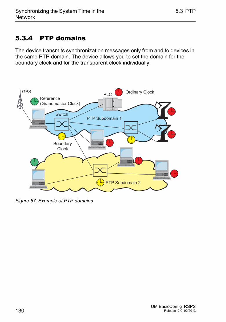
Synchronizing the System Time in the Network
5.3 PTP
5.3.4 PTP domains
The device transmits synchronization messages only from and to devices in the same PTP domain. The device allows you to set the domain for the boundary clock and for the transparent clock individually.
Figure 57: Example of PTP domains
GPSReference(Grandmaster Clock)
BoundaryClock
Ordinary Clock
Switch
PTP Subdomain 2
PTP Subdomain 1
PLC
130UM BasicConfig RSPS
Release 2.0 02/2013
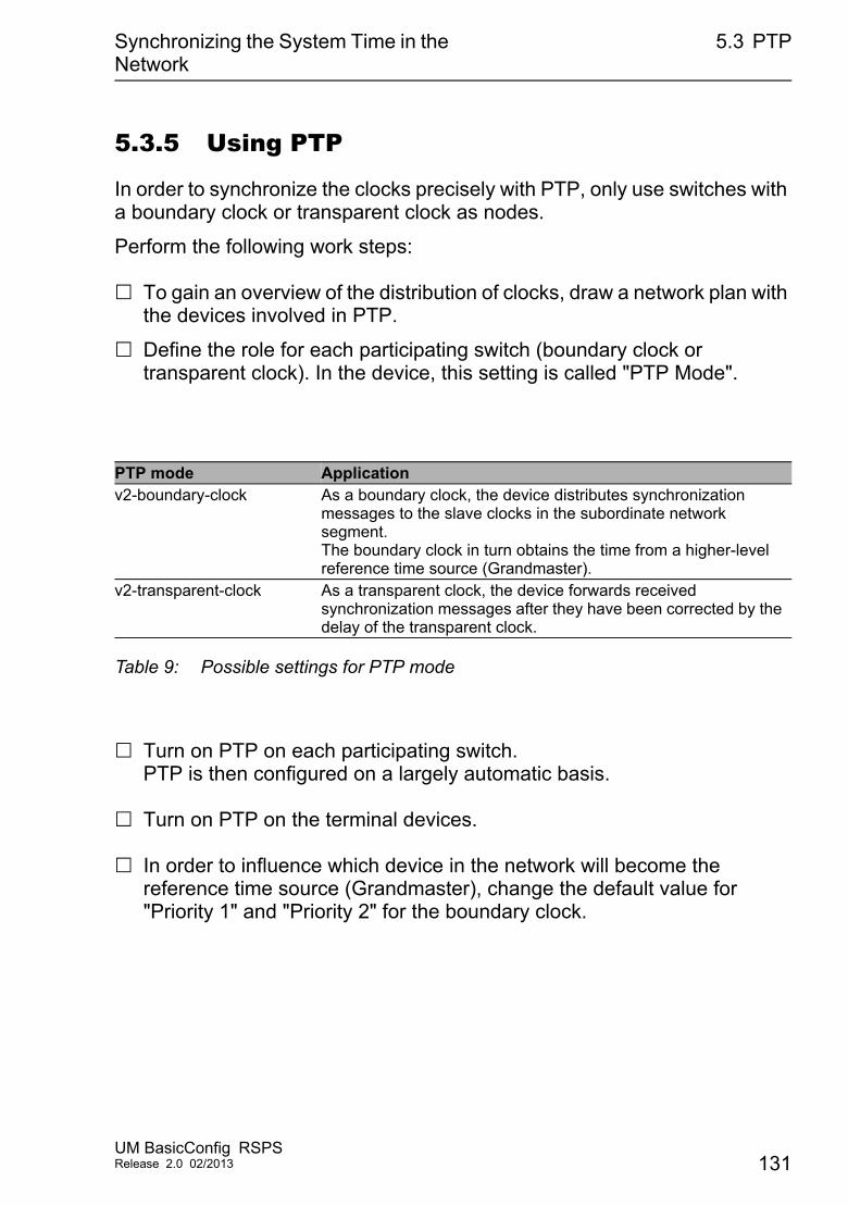
Synchronizing the System Time in the Network
5.3 PTP
5.3.5 Using PTP
In order to synchronize the clocks precisely with PTP, only use switches with a boundary clock or transparent clock as nodes.
Perform the following work steps:
To gain an overview of the distribution of clocks, draw a network plan with the devices involved in PTP.
Define the role for each participating switch (boundary clock or transparent clock). In the device, this setting is called "PTP Mode".
Turn on PTP on each participating switch.PTP is then configured on a largely automatic basis.
Turn on PTP on the terminal devices.
In order to influence which device in the network will become the reference time source (Grandmaster), change the default value for "Priority 1" and "Priority 2" for the boundary clock.
PTP mode Applicationv2-boundary-clock As a boundary clock, the device distributes synchronization
messages to the slave clocks in the subordinate network segment. The boundary clock in turn obtains the time from a higher-level reference time source (Grandmaster).
v2-transparent-clock As a transparent clock, the device forwards received synchronization messages after they have been corrected by the delay of the transparent clock.
Table 9: Possible settings for PTP mode
UM BasicConfig RSPSRelease 2.0 02/2013 131

Synchronizing the System Time in the Network
5.3 PTP
132UM BasicConfig RSPS
Release 2.0 02/2013
Network Load Control
6 Network Load Control
The device features a number of functions that reduce the network load:
Direct packet distribution Multicasts Rate limiter Prioritization - QoS Flow control
UM BasicConfig RSPSRelease 2.0 02/2013 133
Network Load Control 6.1 Direct Packet Distribution
6.1 Direct Packet Distribution
The device reduces the network load with direct packet distribution.
On each of its ports, the device learns the sender MAC address of received data packets. The device stores the combination “port and MAC address” in its MAC address table (FDB).
By applying the “store-and-forward” method, the device buffers data received and checks it for validity before forwarding it. The device rejects invalid and defective data packets.
134UM BasicConfig RSPS
Release 2.0 02/2013
Network Load Control 6.1 Direct Packet Distribution
6.1.1 Learning MAC addresses
If the device receives a data packet, it checks whether the MAC address of the sender is already stored in the MAC address table (FDB). If the MAC address of the sender is unknown, the device generates a new entry. The device then compares the destination MAC address of the data packet with the entries stored in the MAC address table (FDB): The device sends packets with a known destination MAC address directly
to ports that have already received data packets from this MAC address. The device floods data packets with unknown destination addresses, that
is, the device forwards these data packets to all ports.
6.1.2 Aging of learned MAC addresses
Addresses that have not been detected by the device for an adjustable period of time (aging time) are deleted from the MAC address table (FDB) by the device. A reboot or resetting of the MAC address table deletes the entries in the MAC address table (FDB).
UM BasicConfig RSPSRelease 2.0 02/2013 135
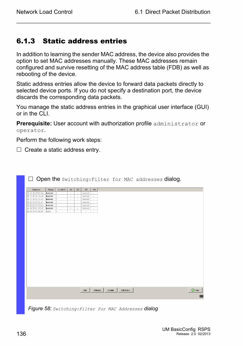
Network Load Control 6.1 Direct Packet Distribution
6.1.3 Static address entries
In addition to learning the sender MAC address, the device also provides the option to set MAC addresses manually. These MAC addresses remain configured and survive resetting of the MAC address table (FDB) as well as rebooting of the device.
Static address entries allow the device to forward data packets directly to selected device ports. If you do not specify a destination port, the device discards the corresponding data packets.
You manage the static address entries in the graphical user interface (GUI) or in the CLI.
Prerequisite: User account with authorization profile administrator or operator.
Perform the following work steps:
Create a static address entry.
Open the Switching:Filter for MAC addresses dialog.
Figure 58: Switching:Filter for MAC Addresses dialog
136UM BasicConfig RSPS
Release 2.0 02/2013
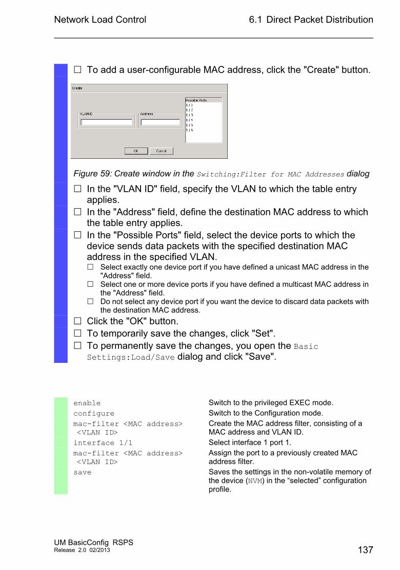
Network Load Control 6.1 Direct Packet Distribution
To add a user-configurable MAC address, click the "Create" button.
Figure 59: Create window in the Switching:Filter for MAC Addresses dialog
In the "VLAN ID" field, specify the VLAN to which the table entry applies.
In the "Address" field, define the destination MAC address to which the table entry applies.
In the "Possible Ports" field, select the device ports to which the device sends data packets with the specified destination MAC address in the specified VLAN. Select exactly one device port if you have defined a unicast MAC address in the
"Address" field. Select one or more device ports if you have defined a multicast MAC address in
the "Address" field. Do not select any device port if you want the device to discard data packets with
the destination MAC address.
Click the "OK" button. To temporarily save the changes, click "Set". To permanently save the changes, you open the Basic
Settings:Load/Save dialog and click "Save".
enable Switch to the privileged EXEC mode.configure Switch to the Configuration mode.mac-filter <MAC address> <VLAN ID>
Create the MAC address filter, consisting of a MAC address and VLAN ID.
interface 1/1 Select interface 1 port 1.mac-filter <MAC address> <VLAN ID>
Assign the port to a previously created MAC address filter.
save Saves the settings in the non-volatile memory of the device (NVM) in the “selected” configuration profile.
UM BasicConfig RSPSRelease 2.0 02/2013 137
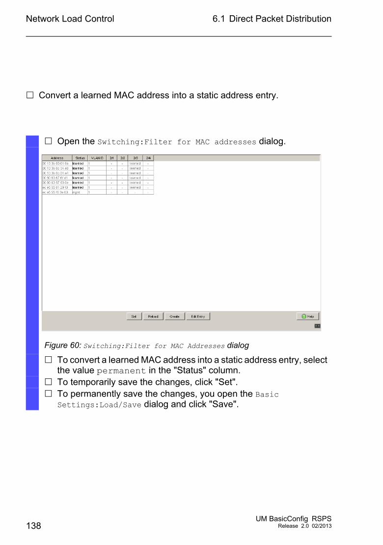
Network Load Control 6.1 Direct Packet Distribution
Convert a learned MAC address into a static address entry.
Open the Switching:Filter for MAC addresses dialog.
Figure 60: Switching:Filter for MAC Addresses dialog
To convert a learned MAC address into a static address entry, select the value permanent in the "Status" column.
To temporarily save the changes, click "Set". To permanently save the changes, you open the Basic
Settings:Load/Save dialog and click "Save".
138UM BasicConfig RSPS
Release 2.0 02/2013
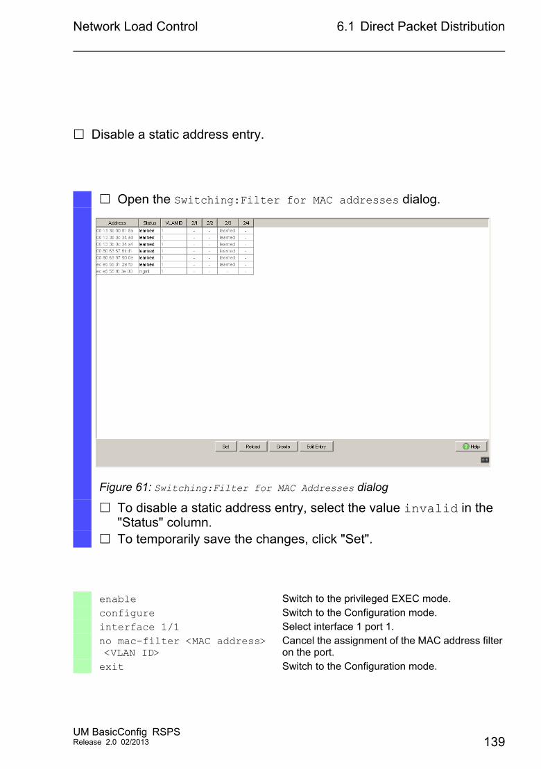
Network Load Control 6.1 Direct Packet Distribution
Disable a static address entry.
Open the Switching:Filter for MAC addresses dialog.
Figure 61: Switching:Filter for MAC Addresses dialog
To disable a static address entry, select the value invalid in the "Status" column.
To temporarily save the changes, click "Set".
enable Switch to the privileged EXEC mode.configure Switch to the Configuration mode.interface 1/1 Select interface 1 port 1.no mac-filter <MAC address> <VLAN ID>
Cancel the assignment of the MAC address filter on the port.
exit Switch to the Configuration mode.
UM BasicConfig RSPSRelease 2.0 02/2013 139
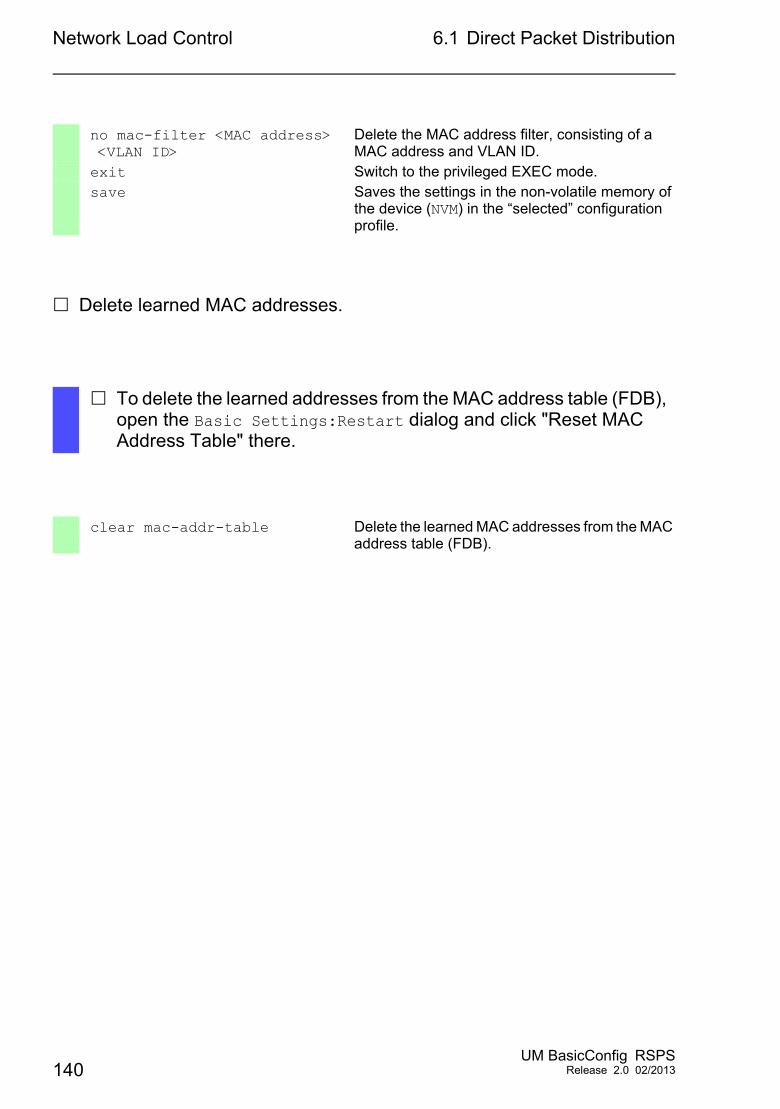
Network Load Control 6.1 Direct Packet Distribution
Delete learned MAC addresses.
no mac-filter <MAC address> <VLAN ID>
Delete the MAC address filter, consisting of a MAC address and VLAN ID.
exit Switch to the privileged EXEC mode.save Saves the settings in the non-volatile memory of
the device (NVM) in the “selected” configuration profile.
To delete the learned addresses from the MAC address table (FDB), open the Basic Settings:Restart dialog and click "Reset MAC Address Table" there.
clear mac-addr-table Delete the learned MAC addresses from the MAC address table (FDB).
140UM BasicConfig RSPS
Release 2.0 02/2013
Network Load Control 6.2 Multicasts
6.2 Multicasts
By default, the device floods data packets with a multicast address, that is, the device forwards the data packets to all ports. This leads to an increased network load.
The use of IGMP snooping can reduce the network load caused by multicast data traffic. IGMP snooping allows the device to send multicast data packets only on those ports to which devices “interested” in multicast are connected.
6.2.1 Example of a Multicast Application
Surveillance cameras transmit images to monitors in the machine room and in the monitoring room. With an IP multicast transmission, the cameras transmit their graphic data over the network in multicast packets.
The Internet Group Management Protocol (IGMP) organizes the multicast data traffic between the multicast routers and the monitors. The switches in the network between the multicast routers and the monitors monitor the IGMP data traffic continuously (“IGMP snooping”).
Switches register logins for receiving a multicast stream (IGMP report). The device then creates an entry in the MAC address table (FDB) and forwards multicast packets only to the ports on which it has previously received IGMP reports.
UM BasicConfig RSPSRelease 2.0 02/2013 141
Network Load Control 6.2 Multicasts
6.2.2 IGMP snooping
The Internet Group Management Protocol (IGMP) describes the distribution of multicast information between routers and connected receivers on Layer 3. “IGMP snooping” describes the function of a switch of continuously monitoring IGMP traffic and optimizing its own transmission settings for this data traffic.
The IGMP snooping function in the device operates according to RFC 4541 (Considerations for Internet Group Management Protocol (IGMP) and Multicast Listener Discovery (MLD) Snooping Switches).
Multicast routers with an active IGMP function periodically request (query) registration of multicast streams in order to determine the associated IP multicast group members. IP multicast group members reply with a Report message. This Report message contains all the parameters required by IGMP. The multicast router enters the IP multicast group address from the Report message in its routing table. This causes it to forward data packets with this IP multicast group in the destination address field according to its routing table.
Receivers log out with a “Leave” message when leaving a multicast group (IGMP version 2 and higher) and do not send any more Report messages. The multicast router removes the routing table entry of a receiver if it does not receive any more Report messages from this receiver within a certain time (aging time).
If several IGMP multicast routers are in the same network, then the device with the smaller IP address takes over the query function. If there are no multicast routers on the network, then you have the option to turn on the query function in an appropriately equipped switch.
A switch that connects one multicast receiver with a multicast router analyzes the IGMP information with the IGMP snooping method.
The IGMP snooping method also makes it possible for switches to use the IGMP function. A switch stores the MAC addresses derived from IP addresses of the multicast receivers as recognized multicast addresses in its MAC address table (FDB). In addition, the switch identifies the ports on which it has received reports for a specific multicast address. In this way the switch transmits multicast packets exclusively on ports to which multicast receivers are connected. The other ports do not receive these packets.
142UM BasicConfig RSPS
Release 2.0 02/2013
Network Load Control 6.2 Multicasts
A special feature of the device is the possibility of determining the processing of data packets with unknown multicast addresses. Depending on the setting, the device discards these data packets or forwards them to all ports. By default, the device transmits the data packets only to ports with connected devices, which in turn receive query packets. You also have the option of additionally sending known multicast packets to query ports.
UM BasicConfig RSPSRelease 2.0 02/2013 143
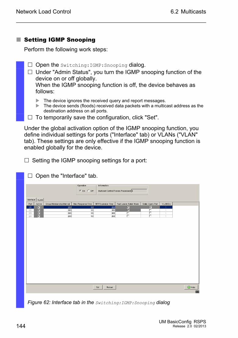
Network Load Control 6.2 Multicasts
Setting IGMP SnoopingPerform the following work steps:
Under the global activation option of the IGMP snooping function, you define individual settings for ports ("Interface" tab) or VLANs ("VLAN" tab). These settings are only effective if the IGMP snooping function is enabled globally for the device.
Setting the IGMP snooping settings for a port:
Open the Switching:IGMP:Snooping dialog. Under "Admin Status", you turn the IGMP snooping function of the
device on or off globally.When the IGMP snooping function is off, the device behaves as follows:
The device ignores the received query and report messages. The device sends (floods) received data packets with a multicast address as the
destination address on all ports.
To temporarily save the configuration, click "Set".
Open the "Interface" tab.
Figure 62: Interface tab in the Switching:IGMP:Snooping dialog
144UM BasicConfig RSPS
Release 2.0 02/2013
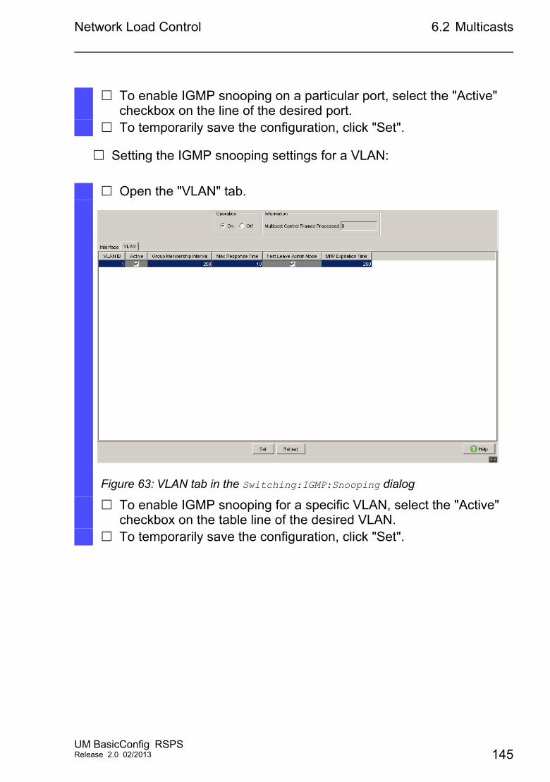
Network Load Control 6.2 Multicasts
Setting the IGMP snooping settings for a VLAN:
To enable IGMP snooping on a particular port, select the "Active" checkbox on the line of the desired port.
To temporarily save the configuration, click "Set".
Open the "VLAN" tab.
Figure 63: VLAN tab in the Switching:IGMP:Snooping dialog
To enable IGMP snooping for a specific VLAN, select the "Active" checkbox on the table line of the desired VLAN.
To temporarily save the configuration, click "Set".
UM BasicConfig RSPSRelease 2.0 02/2013 145
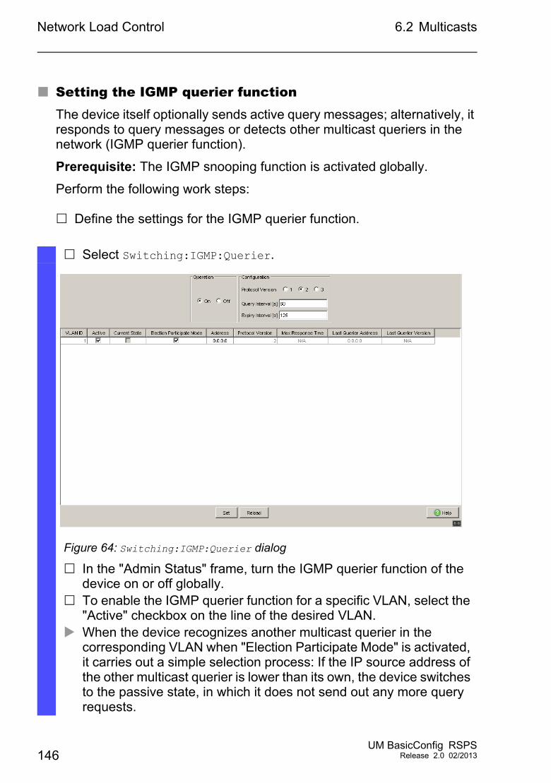
Network Load Control 6.2 Multicasts
Setting the IGMP querier functionThe device itself optionally sends active query messages; alternatively, it responds to query messages or detects other multicast queriers in the network (IGMP querier function).
Prerequisite: The IGMP snooping function is activated globally.
Perform the following work steps:
Define the settings for the IGMP querier function.
Select Switching:IGMP:Querier.
Figure 64: Switching:IGMP:Querier dialog
In the "Admin Status" frame, turn the IGMP querier function of the device on or off globally.
To enable the IGMP querier function for a specific VLAN, select the "Active" checkbox on the line of the desired VLAN.
When the device recognizes another multicast querier in the corresponding VLAN when "Election Participate Mode" is activated, it carries out a simple selection process: If the IP source address of the other multicast querier is lower than its own, the device switches to the passive state, in which it does not send out any more query requests.
146UM BasicConfig RSPS
Release 2.0 02/2013
Network Load Control 6.2 Multicasts
IGMP Snooping Enhancements (Table)The Switching:IGMP:Snooping Enhancements dialog gives you access to enhanced settings for the IGMP snooping function. You enable or disable the settings on a per port basis in a VLAN.
The following settings are possible:
StaticUse this setting to set the port as a static query port. The device sends all IGMP messages on a static query port, even if it has previously received no IGMP query messages on this port. If the static option is disabled, the device sends IGMP messages on this port only if it has previously received IGMP query messages. If that is the case, the entry shows L (“learned”).
Learn by LLDPA port with this setting automatically discovers other Hirschmann devices via LLDP (Link Layer Discovery Protocol). The device then learns the IGMP query status of this port from these Hirschmann devices and configures the IGMP query function accordingly. The ALA entry indicates that the Learn by LLDP function is enabled. If the device has found another Hirschmann device on this port in this VLAN, the entry also shows an A (“Automatic”).
Forward AllWith this setting, the device sends the data packets addressed to a multicast address on this port. The setting is suitable in the following situations, for example:– For diagnostic purposes.– For devices in an MRP ring: After the ring is switched, the Forward
All function allows rapid reconfiguration of the network for data packets with registered multicast destination addresses. Activate the Forward All function on all ring ports.
Under "Address", you specify the IP multicast address that the device inserts as the sender address in generated query requests. You use the address of the multicast router.
To temporarily save the configuration, click "Set".
UM BasicConfig RSPSRelease 2.0 02/2013 147
Network Load Control 6.2 Multicasts
Prerequisite: The IGMP snooping function is activated globally.
To configure enhanced IGMP snooping settings, proceed as follows:
Configuring multicastsThe device allows you to configure the exchange of multicast data packets. The device provides different options depending on whether the data packets are to be sent to unknown or known multicast receivers.
The settings for unknown multicast addresses are global for the entire device. The following options can be selected:
The device discards unknown multicasts.
The device sends unknown multicasts on all ports.
The device sends unknown multicasts exclusively on ports that have previously received query messages (query ports).
Note: The exchange settings for unknown multicast addresses also apply to the reserved IP addresses from the “Local Network Control Block” (224.0.0.0-224.0.0.255). This behavior may affect higher-level routing protocols.
Open the Switching:IGMP:Snooping Enhancements dialog. Double-click the desired port in the desired VLAN. To activate one or more functions, select the corresponding options. Click the "OK" button. To temporarily save the configuration, click "Set".enable Switch to the privileged EXEC mode.vlan database Switch to the VLAN mode.igmp-snooping vlan-id 1 forward-all 1/1
Activate the Forward All function for slot 1 / port 1 in VLAN 1.
148UM BasicConfig RSPS
Release 2.0 02/2013
Network Load Control 6.2 Multicasts
For each VLAN, you define the sending of multicast packets to known multicast addresses individually. The following options can be selected:
The device sends known multicasts on the ports that have previously received query messages (query ports) and to the registered ports. Registered ports are ports with multicast receivers registered with the corresponding multicast group. This option ensures that the transfer works with basic applications without further configuration.
The device sends out known multicasts only on the registered ports. The advantage of this setting is that it uses the available bandwidth optimally through direct distribution.
Prerequisite: The IGMP snooping function is activated globally.
To configure multicasts, proceed as follows:
Open the Switching:IGMP:Multicasts dialog. In the "Configuration" frame, you specify how the device sends data
packets to unknown multicast addresses. Send to Query Ports
The device sends packets with unknown multicast address to all query ports. Send to All Ports
The device sends data packets with an unknown multicast address to all ports. Discard
The device discards all packets with an unknown multicast address.
In the "Known Multicasts" column, you specify how the device sends data packets to known multicast addresses in the corresponding VLAN. Click the relevant field and select the desired option.
To temporarily save the configuration, click "Set".
UM BasicConfig RSPSRelease 2.0 02/2013 149
Network Load Control 6.3 Rate limiter
6.3 Rate limiter
The rate limiter function allows you to limit the data traffic on the ports in order to ensure stable operation even when there is a high level of traffic. The rate limitation is performed individually for each port, as well as separately for inbound and outbound traffic.
If the data rate on a port exceeds the defined limit, the device discards the overload on this port.
Rate limitation occurs entirely on layer 2. In the process, the rate limiter function ignores protocol information on higher levels such as IP or TCP. This may affect the TCP traffic.
To minimize these effects, use the following options: Limit the rate limitation to certain frame types, for example, broadcasts,
multicasts, and unicasts with unknown destination addresses. Limit the outbound data traffic instead of the inbound traffic. The outbound
rate limitation works better with TCP flow control due to device-internal buffering of the data packets.
Increase the aging time for learned unicast addresses (see on page 135 “Aging of learned MAC addresses”).
To configure the rate limiter function, proceed as follows:
150UM BasicConfig RSPS
Release 2.0 02/2013
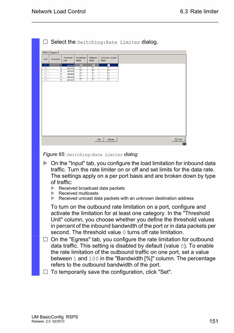
Network Load Control 6.3 Rate limiter
Select the Switching:Rate Limiter dialog.
Figure 65: Switching:Rate Limiter dialog
On the "Input" tab, you configure the load limitation for inbound data traffic. Turn the rate limiter on or off and set limits for the data rate. The settings apply on a per port basis and are broken down by type of traffic: Received broadcast data packets Received multicasts Received unicast data packets with an unknown destination address
To turn on the outbound rate limitation on a port, configure and activate the limitation for at least one category. In the "Threshold Unit" column, you choose whether you define the threshold values in percent of the inbound bandwidth of the port or in data packets per second. The threshold value 0 turns off rate limitation.
On the "Egress" tab, you configure the rate limitation for outbound data traffic. This setting is disabled by default (value 0). To enable the rate limitation of the outbound traffic on one port, set a value between 1 and 100 in the "Bandwidth [%]" column. The percentage refers to the outbound bandwidth of the port.
To temporarily save the configuration, click "Set".
UM BasicConfig RSPSRelease 2.0 02/2013 151
Network Load Control 6.4 QoS/Priority
6.4 QoS/Priority
QoS (Quality of Service) is a procedure defined in IEEE 802.1D. It is used to distribute resources in the network. QoS allows you to prioritize the data of important applications.
Prioritizing prevents data traffic with lower priority from interfering with delay-sensitive data traffic, especially when there is a heavy network load. Delay-sensitive data traffic includes, for example, voice, video, and real-time data.
152UM BasicConfig RSPS
Release 2.0 02/2013
Network Load Control 6.4 QoS/Priority
6.4.1 Description of Prioritization
For data traffic prioritization, traffic classes are defined in the device. The device prioritizes higher traffic classes over lower traffic classes. The number of traffic classes depends on the device type.
To provide for optimal data flow for delay-sensitive data, you assign higher traffic classes to this data. You assign lower traffic classes to data that is less sensitive to delay.
Assigning traffic classes to the dataThe device automatically assigns traffic classes to inbound data (traffic classification). The device takes the following classification criteria into account: Methods according to which the device carries out assignment of
received data packets to traffic classes: trustDot1p: The device uses the priority of the data packet
contained in the VLAN tag. trustIpDscp: The device uses the QoS information contained in
the IP header (ToS/DiffServ). untrusted: The device ignores possible priority information within
the data packets and uses the priority of the receiving port directly. The priority assigned to the receiving port.
Both classification criteria are configurable.
During traffic classification, the device uses the following rules: When the receiving port is set to trustDot1p (state on delivery), the
device uses the data packet priority contained in the VLAN tag. When the data packets do not contain a VLAN tag, the device is guided by the priority of the receiving port.
When the receiving port is set to trustIpDscp, the device uses the QoS information (ToS/DiffServ) in the IP header. When the data packets do not contain IP packets, the device is guided by the priority of the receiving port.
When the receiving port is set to untrusted, the device is guided by the priority of the receiving port.
UM BasicConfig RSPSRelease 2.0 02/2013 153
Network Load Control 6.4 QoS/Priority
Prioritizing traffic classesFor prioritization of traffic classes, the device uses the following methods:
„Strict“When transmission of data of a higher traffic class is no longer taking place or the relevant data is still in the queue, the device sends data of the corresponding traffic class. If all traffic classes are prioritized according to the “strict” method, under high network load the device may permanently block the data of lower traffic classes.
„Weighted Fair Queuing“The traffic class is assigned a guaranteed bandwidth. This ensures that the device sends the data traffic of this traffic class even if there is a great deal of data traffic in higher traffic classes.
6.4.2 Handling of Received Priority Information
Applications label data packets with the following prioritization information: VLAN priority based on IEEE 802.1Q/ 802.1D (Layer 2) Type-of-Service (ToS) or DiffServ (DSCP) for VLAN Management IP
packets (Layer 3)
The device offers the following options for evaluating this priority information: trustDot1p
The device assigns VLAN-tagged data packets to the different traffic classes according to their VLAN priorities. The corresponding allocation is configurable. The device assigns the priority of the receiving port to data packets it receives without a VLAN tag.
trustIpDscpThe device assigns the IP packets to the different traffic classes according to the DSCP value in the IP header, even if the packet was also VLAN-tagged. The corresponding allocation is configurable. The device prioritizes non-IP packets according to the priority of the receiving port.
untrustedThe device ignores the priority information in the data packets and assigns the priority of the receiving port to them.
154UM BasicConfig RSPS
Release 2.0 02/2013
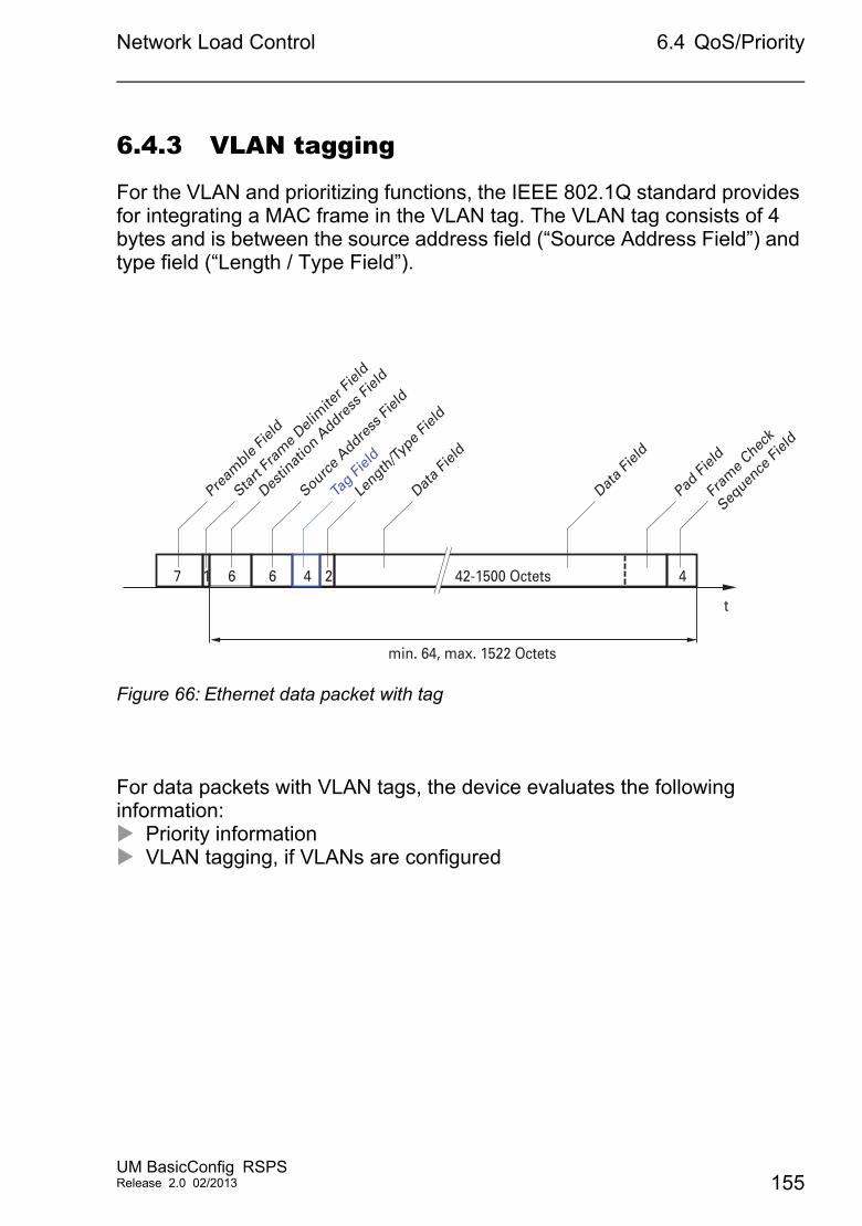
Network Load Control 6.4 QoS/Priority
6.4.3 VLAN tagging
For the VLAN and prioritizing functions, the IEEE 802.1Q standard provides for integrating a MAC frame in the VLAN tag. The VLAN tag consists of 4 bytes and is between the source address field (“Source Address Field”) and type field (“Length / Type Field”).
Figure 66: Ethernet data packet with tag
For data packets with VLAN tags, the device evaluates the following information: Priority information VLAN tagging, if VLANs are configured
t
min. 64, max. 1522 Octets
Pream
ble Fie
ld
Start
Fram
e Deli
mite
r Fiel
d
Destin
atio
n Addre
ss Fi
eld
Source A
ddress
Field
Tag Fi
eld
Data F
ield
Length
/Type F
ield
Data F
ield
Pad Fi
eld
Fram
e Chec
k
Sequen
ce Fi
eld
42-1500 Octets 424667 1
UM BasicConfig RSPSRelease 2.0 02/2013 155
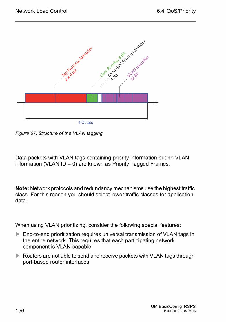
Network Load Control 6.4 QoS/Priority
Figure 67: Structure of the VLAN tagging
Data packets with VLAN tags containing priority information but no VLAN information (VLAN ID = 0) are known as Priority Tagged Frames.
Note: Network protocols and redundancy mechanisms use the highest traffic class. For this reason you should select lower traffic classes for application data.
When using VLAN prioritizing, consider the following special features:
End-to-end prioritization requires universal transmission of VLAN tags in the entire network. This requires that each participating network component is VLAN-capable.
Routers are not able to send and receive packets with VLAN tags through port-based router interfaces.
t
4 Octets
User P
riorit
y, 3 B
it
Canonica
l Form
at Id
entif
ier
1 Bit VLA
N Iden
tifier
12 B
itTag P
roto
col Id
entif
ier
2 x 8
Bit
156UM BasicConfig RSPS
Release 2.0 02/2013
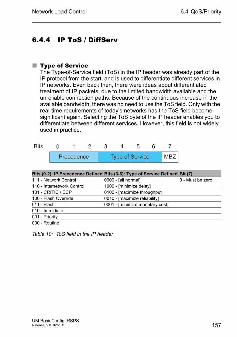
Network Load Control 6.4 QoS/Priority
6.4.4 IP ToS / DiffServ
Type of ServiceThe Type-of-Service field (ToS) in the IP header was already part of the IP protocol from the start, and is used to differentiate different services in IP networks. Even back then, there were ideas about differentiated treatment of IP packets, due to the limited bandwidth available and the unreliable connection paths. Because of the continuous increase in the available bandwidth, there was no need to use the ToS field. Only with the real-time requirements of today’s networks has the ToS field become significant again. Selecting the ToS byte of the IP header enables you to differentiate between different services. However, this field is not widely used in practice.
Bits (0-2): IP Precedence Defined Bits (3-6): Type of Service Defined Bit (7) 111 - Network Control 0000 - [all normal] 0 - Must be zero110 - Internetwork Control 1000 - [minimize delay]101 - CRITIC / ECP 0100 - [maximize throughput100 - Flash Override 0010 - [maximize reliability]011 - Flash 0001 - [minimize monetary cost]010 - Immidiate001 - Priority000 - Routine
Table 10: ToS field in the IP header
Bits 0 1 32 4 5 6 7
MBZPrecedence Type of Service
UM BasicConfig RSPSRelease 2.0 02/2013 157
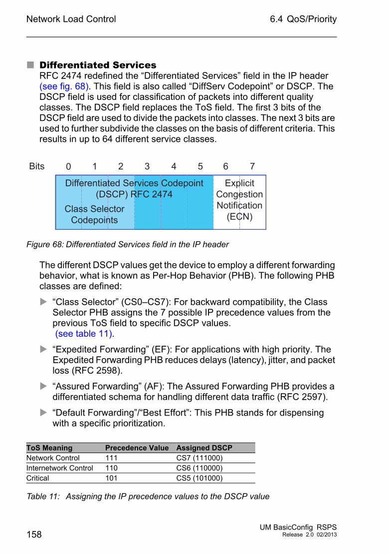
Network Load Control 6.4 QoS/Priority
Differentiated ServicesRFC 2474 redefined the “Differentiated Services” field in the IP header (see fig. 68). This field is also called “DiffServ Codepoint” or DSCP. The DSCP field is used for classification of packets into different quality classes. The DSCP field replaces the ToS field. The first 3 bits of the DSCP field are used to divide the packets into classes. The next 3 bits are used to further subdivide the classes on the basis of different criteria. This results in up to 64 different service classes.
Figure 68: Differentiated Services field in the IP header
The different DSCP values get the device to employ a different forwarding behavior, what is known as Per-Hop Behavior (PHB). The following PHB classes are defined:
“Class Selector” (CS0–CS7): For backward compatibility, the Class Selector PHB assigns the 7 possible IP precedence values from the previous ToS field to specific DSCP values. (see table 11).
“Expedited Forwarding” (EF): For applications with high priority. The Expedited Forwarding PHB reduces delays (latency), jitter, and packet loss (RFC 2598).
“Assured Forwarding” (AF): The Assured Forwarding PHB provides a differentiated schema for handling different data traffic (RFC 2597).
“Default Forwarding”/“Best Effort”: This PHB stands for dispensing with a specific prioritization.
ToS Meaning Precedence Value Assigned DSCPNetwork Control 111 CS7 (111000)Internetwork Control 110 CS6 (110000)Critical 101 CS5 (101000)
Table 11: Assigning the IP precedence values to the DSCP value
Bits 0 1 32 4 5 6 7
ExplicitCongestionNotification
(ECN)
Differentiated Services Codepoint(DSCP) RFC 2474
Class SelectorCodepoints
158UM BasicConfig RSPS
Release 2.0 02/2013
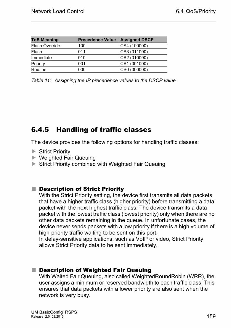
Network Load Control 6.4 QoS/Priority
6.4.5 Handling of traffic classes
The device provides the following options for handling traffic classes:
Strict Priority Weighted Fair Queuing Strict Priority combined with Weighted Fair Queuing
Description of Strict PriorityWith the Strict Priority setting, the device first transmits all data packets that have a higher traffic class (higher priority) before transmitting a data packet with the next highest traffic class. The device transmits a data packet with the lowest traffic class (lowest priority) only when there are no other data packets remaining in the queue. In unfortunate cases, the device never sends packets with a low priority if there is a high volume of high-priority traffic waiting to be sent on this port.In delay-sensitive applications, such as VoIP or video, Strict Priority allows Strict Priority data to be sent immediately.
Description of Weighted Fair QueuingWith Waited Fair Queuing, also called WeightedRoundRobin (WRR), the user assigns a minimum or reserved bandwidth to each traffic class. This ensures that data packets with a lower priority are also sent when the network is very busy.
Flash Override 100 CS4 (100000)Flash 011 CS3 (011000)Immediate 010 CS2 (010000)Priority 001 CS1 (001000)Routine 000 CS0 (000000)
ToS Meaning Precedence Value Assigned DSCP
Table 11: Assigning the IP precedence values to the DSCP value
UM BasicConfig RSPSRelease 2.0 02/2013 159
Network Load Control 6.4 QoS/Priority
The weighting values range from 0% to 100% of the available bandwidth, in steps of 1%.
A weighting of 0 is equivalent to a "no bandwidth" setting.
The sum of the individual bandwidths may add up to 100%.
If you assign Weighted Fair Queuing to all traffic classes, the entire bandwidth of the corresponding port is available to you.
When combining Weighted Fair Queuing with Strict Priority, ensure that the highest traffic class of Weighted Fair Queuing is lower than the lowest traffic class of Strict Priority.
When you combine Weighted Fair Queuing with Strict Priority, a high Strict Priority network load can significantly reduce the bandwidth available for Weighted Fair Queuing.
6.4.6 Management prioritization
In order for you to have full access to the management of the device, even when there is a high network load, the device allows you to prioritize management packets.When prioritizing management packets, the device sends the management packets with priority information.
On Layer 2, the device modifies the VLAN priority in the VLAN tag.For this function to be useful, the configuration of the corresponding ports must permit the sending of packets with a VLAN tag.
On Layer 3, the device modifies the IP-DSCP value.
160UM BasicConfig RSPS
Release 2.0 02/2013
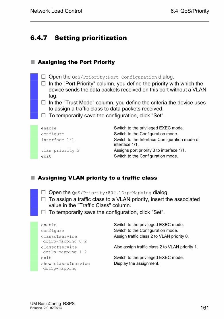
Network Load Control 6.4 QoS/Priority
6.4.7 Setting prioritization
Assigning the Port Priority
Assigning VLAN priority to a traffic class
Open the QoS/Priority:Port Configuration dialog. In the "Port Priority" column, you define the priority with which the
device sends the data packets received on this port without a VLAN tag.
In the "Trust Mode" column, you define the criteria the device uses to assign a traffic class to data packets received.
To temporarily save the configuration, click "Set".
enable Switch to the privileged EXEC mode.configure Switch to the Configuration mode.interface 1/1 Switch to the Interface Configuration mode of
interface 1/1.vlan priority 3 Assigns port priority 3 to interface 1/1.exit Switch to the Configuration mode.
Open the QoS/Priority:802.1D/p-Mapping dialog. To assign a traffic class to a VLAN priority, insert the associated
value in the "Traffic Class" column. To temporarily save the configuration, click "Set".
enable Switch to the privileged EXEC mode.configure Switch to the Configuration mode.classofservice dot1p-mapping 0 2
Assign traffic class 2 to VLAN priority 0.
classofservice dot1p-mapping 1 2
Also assign traffic class 2 to VLAN priority 1.
exit Switch to the privileged EXEC mode.show classofservice dot1p-mapping
Display the assignment.
UM BasicConfig RSPSRelease 2.0 02/2013 161
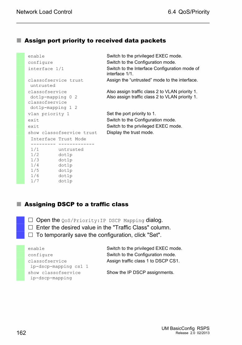
Network Load Control 6.4 QoS/Priority
Assign port priority to received data packets
Assigning DSCP to a traffic class
enable Switch to the privileged EXEC mode.configure Switch to the Configuration mode.interface 1/1 Switch to the Interface Configuration mode of
interface 1/1.classofservice trust untrusted
Assign the “untrusted” mode to the interface.
classofservice dot1p-mapping 0 2classofservice dot1p-mapping 1 2
Also assign traffic class 2 to VLAN priority 1.Also assign traffic class 2 to VLAN priority 1.
vlan priority 1 Set the port priority to 1.exit Switch to the Configuration mode.exit Switch to the privileged EXEC mode.show classofservice trust Display the trust mode. Interface Trust Mode --------- ------------- 1/1 untrusted 1/2 dot1p 1/3 dot1p 1/4 dot1p 1/5 dot1p 1/6 dot1p 1/7 dot1p
Open the QoS/Priority:IP DSCP Mapping dialog. Enter the desired value in the "Traffic Class" column. To temporarily save the configuration, click "Set".
enable Switch to the privileged EXEC mode.configure Switch to the Configuration mode.classofservice ip-dscp-mapping cs1 1
Assign traffic class 1 to DSCP CS1.
show classofservice ip-dscp-mapping
Show the IP DSCP assignments.
162UM BasicConfig RSPS
Release 2.0 02/2013
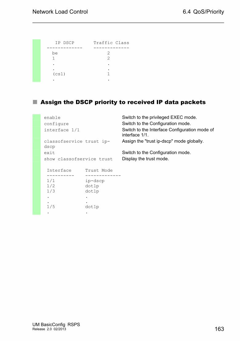
Network Load Control 6.4 QoS/Priority
Assign the DSCP priority to received IP data packets
IP DSCP Traffic Class ------------- ------------- be 2 1 2 . . . . (cs1) 1 . .
enable Switch to the privileged EXEC mode.configure Switch to the Configuration mode.interface 1/1 Switch to the Interface Configuration mode of
interface 1/1.classofservice trust ip-dscp
Assign the "trust ip-dscp" mode globally.
exit Switch to the Configuration mode.show classofservice trust Display the trust mode.
Interface Trust Mode ---------- ------------- 1/1 ip-dscp 1/2 dot1p 1/3 dot1p . . . . 1/5 dot1p . .
UM BasicConfig RSPSRelease 2.0 02/2013 163
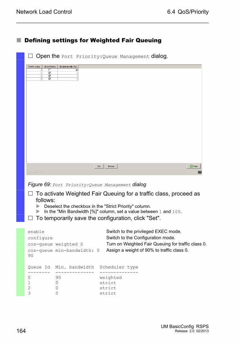
Network Load Control 6.4 QoS/Priority
Defining settings for Weighted Fair Queuing
Open the Port Priority:Queue Management dialog.
Figure 69: Port Priority:Queue Management dialog
To activate Weighted Fair Queuing for a traffic class, proceed as follows: Deselect the checkbox in the "Strict Priority" column. In the "Min Bandwidth [%]" column, set a value between 1 and 100.
To temporarily save the configuration, click "Set".
enable Switch to the privileged EXEC mode.configure Switch to the Configuration mode.cos-queue weighted 0 Turn on Weighted Fair Queuing for traffic class 0.cos-queue min-bandwidth: 0 90
Assign a weight of 90% to traffic class 0.
Queue Id Min. bandwidth Scheduler type-------- -------------- --------------0 90 weighted1 0 strict2 0 strict3 0 strict
164UM BasicConfig RSPS
Release 2.0 02/2013
Network Load Control 6.4 QoS/Priority
Configuring Traffic Shaping on a port
Configuring Layer 2 management priority
enable Switch to the privileged EXEC mode.configure Switch to the Configuration mode.interface 1/2 Switch to the interface configuration mode for
port 1.2.traffic-shape bw 50 Limit the maximum bandwidth of port 1/2 to 50%.exit Switch to the Configuration mode.exit Switch to the privileged EXEC mode.show traffic-shape Display the traffic shaping configuration.
Interface Shaping rate--------- ------------1/1 0 %1/2 50 %1/3 0 %1/4 0 %
Open the QoS/Priority:Global dialog. In the "VLAN Priority for Management packets" field, set the VLAN
priority with which the device sends management data packets. To temporarily save the configuration, click "Set".
enable Switch to the privileged EXEC mode.network management priority dot1p 7
Assign the VLAN priority of 7 to management packets. The device sends management packets with the highest priority.
show network parms Displays the management VLAN priority.
IPv4 Network------------...Management VLAN priority....................7...
UM BasicConfig RSPSRelease 2.0 02/2013 165
Network Load Control 6.4 QoS/Priority
Configuring Layer 3 management priority
Open the QoS/Priority:Global dialog. In the "IP DSCP Value for Management packets" field, set the DSCP
value with which the device sends management data packets. To temporarily save the configuration, click "Set".
enable Switch to the privileged EXEC mode.network management priority ip-dscp 56
Assign the DSCP value of 56 to management packets. The device sends management packets with the highest priority.
show network parms Displays the management VLAN priority.
IPv4 Network------------...Management IP-DSCP value....................56
166UM BasicConfig RSPS
Release 2.0 02/2013
Network Load Control 6.5 Flow Control
6.5 Flow Control
If a large number of data packets are received in the sending queue of a port at the same time, this can cause the port memory to overflow. This happens, for example, when the device receives data on a Gigabit port and forwards it to a port with a lower bandwidth. The device discards surplus data packets.
The flow control mechanism described in standard IEEE 802.3 ensures that no data packets are lost due to a port memory overflowing. Shortly before a port memory is completely full, the device signals to the connected devices that it is not accepting any more data packets from them. In full-duplex mode, the device sends a pause data packet. In half-duplex mode, the device simulates a collision.
The following figure shows how flow control works. Workstations 1, 2, and 3 want to simultaneously transmit a large amount of data to Workstation 4. The combined bandwidth of Workstations 1, 2, and 3 is greater than the bandwidth of Workstation 4. This causes an overflow on the receive queue of port 4. The left funnel symbolizes this status.
If the flow control function on ports 1, 2 and 3 of the device is turned on. The device reacts before the funnel overflows. The funnel on the right illustrates ports 1, 2 and 3 sending a message to the transmitting devices to control the transmition speed. This results in the receiving port no longer being overwhelmed and is able to process the incoming traffic.
UM BasicConfig RSPSRelease 2.0 02/2013 167
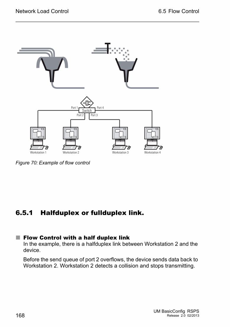
Network Load Control 6.5 Flow Control
Figure 70: Example of flow control
6.5.1 Halfduplex or fullduplex link.
Flow Control with a half duplex linkIn the example, there is a halfduplex link between Workstation 2 and the device.
Before the send queue of port 2 overflows, the device sends data back to Workstation 2. Workstation 2 detects a collision and stops transmitting.
SwitchPort 3Port 2
Port 1 Port 4
Workstation 1 Workstation 2 Workstation 3 Workstation 4
168UM BasicConfig RSPS
Release 2.0 02/2013
Network Load Control 6.5 Flow Control
Flow Control with a full duplex linkIn the example, there is a fullduplex link between Workstation 2 and the device.
Before the send queue of port 2 overflows, the device sends a request to Workstation 2 to include a small break in the sending transmission.
6.5.2 Setting the Flow Control
Perform the following work steps:
Note: When you are using a redundancy function, you deactivate the flow control on the participating device ports. If the flow control and the redundancy function are active at the same time, there is a risk that the redundancy function will not operate as intended.
Open the Switching:Global dialog. Select the "Activate Flow Control" checkbox.
With this setting you activate flow control in the device. Open the Basic Settings:Port Configuration dialog. To turn on the flow control on a port, select the "Flow Control" option
on the corresponding table line. To temporarily save the configuration, click "Set".
UM BasicConfig RSPSRelease 2.0 02/2013 169

Network Load Control 6.5 Flow Control
170UM BasicConfig RSPS
Release 2.0 02/2013
VLANs
7 VLANs
In the simplest case, a virtual LAN (VLAN) consists of a group of network participants in one network segment who can communicate with each other as if they belonged to a separate LAN.
More complex VLANs span out over multiple network segments and are also based on logical (instead of only physical) connections between network participants. VLANs are an element of flexible network design. It is easier to reconfiguring logical connections centrally than cable connections.
The device supports independent VLAN learning in accordance with the IEEE 802.1Q standard which defines the VLAN function.
Although there are many benefits of using VLANs, the following lists the top benefits:
Network load limitingVLANs reduce the network load considerably as the devices transmit broadcast, multicast, and unicast packets with unknown (unlearned) destination addresses exclusively inside the virtual LAN. The rest of the data network forwards traffic as normal.
FlexibilityYou have the option of forming user groups based on the function of the participants apart from their physical location or medium.
ClarityVLANs give networks a clear structure and make maintenance easier.
UM BasicConfig RSPSRelease 2.0 02/2013 171
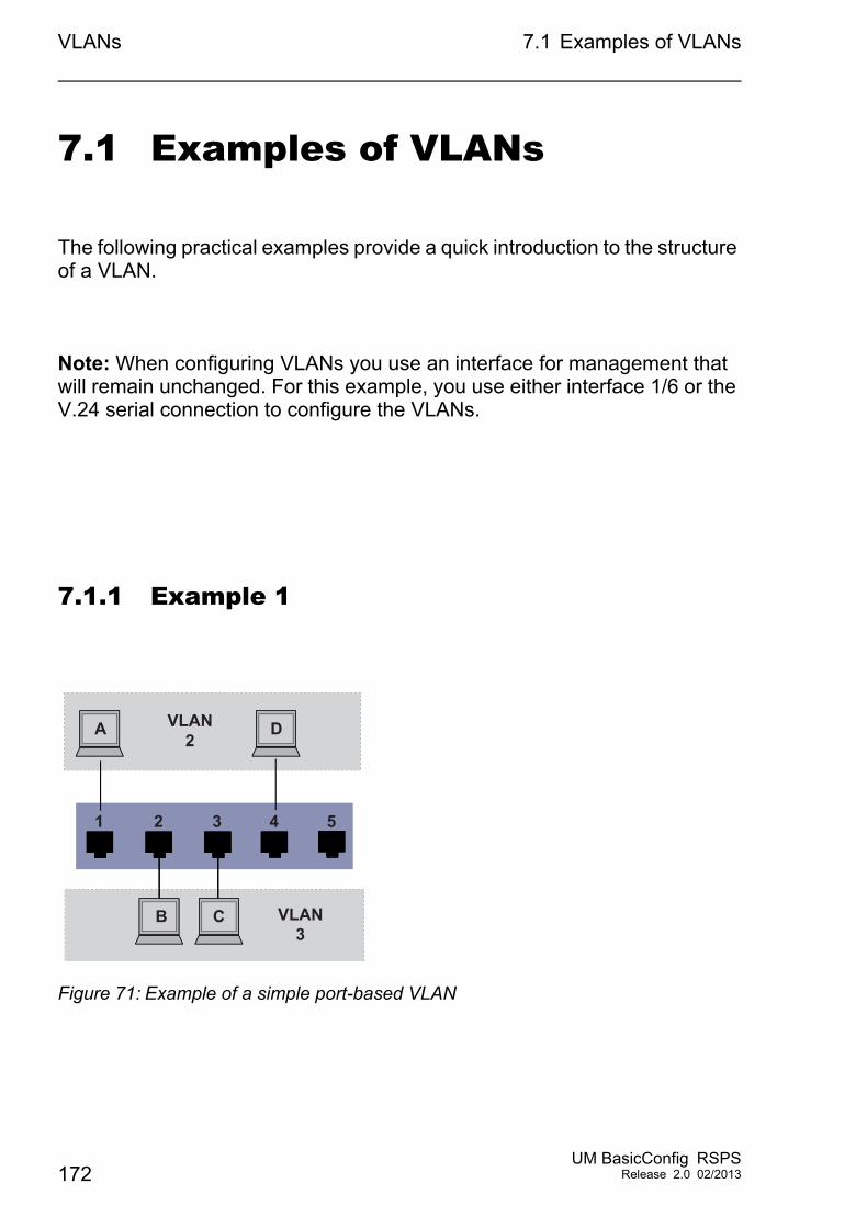
VLANs 7.1 Examples of VLANs
7.1 Examples of VLANs
The following practical examples provide a quick introduction to the structure of a VLAN.
Note: When configuring VLANs you use an interface for management that will remain unchanged. For this example, you use either interface 1/6 or the V.24 serial connection to configure the VLANs.
7.1.1 Example 1
Figure 71: Example of a simple port-based VLAN
1 32
VLAN2
VLAN3
A
B C
D
4 5
172UM BasicConfig RSPS
Release 2.0 02/2013
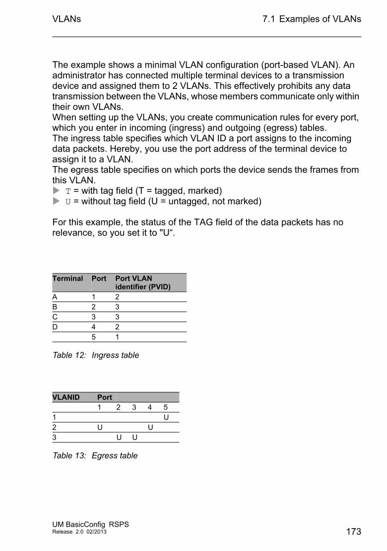
VLANs 7.1 Examples of VLANs
The example shows a minimal VLAN configuration (port-based VLAN). An administrator has connected multiple terminal devices to a transmission device and assigned them to 2 VLANs. This effectively prohibits any data transmission between the VLANs, whose members communicate only within their own VLANs. When setting up the VLANs, you create communication rules for every port, which you enter in incoming (ingress) and outgoing (egress) tables. The ingress table specifies which VLAN ID a port assigns to the incoming data packets. Hereby, you use the port address of the terminal device to assign it to a VLAN.The egress table specifies on which ports the device sends the frames from this VLAN. T = with tag field (T = tagged, marked) U = without tag field (U = untagged, not marked)
For this example, the status of the TAG field of the data packets has no relevance, so you set it to "U“.
Terminal Port Port VLAN identifier (PVID)
A 1 2B 2 3C 3 3D 4 2
5 1
Table 12: Ingress table
VLANID Port1 2 3 4 5
1 U2 U U3 U U
Table 13: Egress table
UM BasicConfig RSPSRelease 2.0 02/2013 173
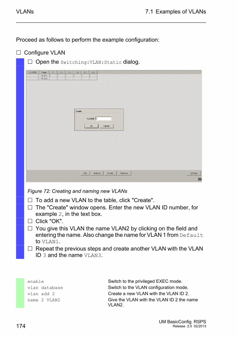
VLANs 7.1 Examples of VLANs
Proceed as follows to perform the example configuration:
Configure VLAN
Open the Switching:VLAN:Static dialog.
Figure 72: Creating and naming new VLANs
To add a new VLAN to the table, click "Create". The "Create" window opens. Enter the new VLAN ID number, for
example 2, in the text box. Click "OK". You give this VLAN the name VLAN2 by clicking on the field and
entering the name. Also change the name for VLAN 1 from Default to VLAN1.
Repeat the previous steps and create another VLAN with the VLAN ID 3 and the name VLAN3.
enable Switch to the privileged EXEC mode.vlan database Switch to the VLAN configuration mode.vlan add 2 Create a new VLAN with the VLAN ID 2.name 2 VLAN2 Give the VLAN with the VLAN ID 2 the name
VLAN2.
174UM BasicConfig RSPS
Release 2.0 02/2013
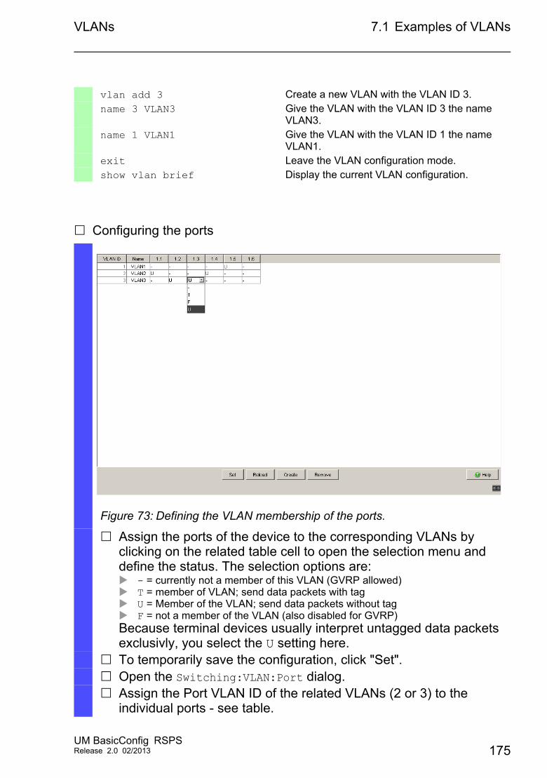
VLANs 7.1 Examples of VLANs
Configuring the ports
vlan add 3 Create a new VLAN with the VLAN ID 3.name 3 VLAN3 Give the VLAN with the VLAN ID 3 the name
VLAN3.name 1 VLAN1 Give the VLAN with the VLAN ID 1 the name
VLAN1.exit Leave the VLAN configuration mode.show vlan brief Display the current VLAN configuration.
Figure 73: Defining the VLAN membership of the ports.
Assign the ports of the device to the corresponding VLANs by clicking on the related table cell to open the selection menu and define the status. The selection options are: - = currently not a member of this VLAN (GVRP allowed) T = member of VLAN; send data packets with tag U = Member of the VLAN; send data packets without tag F = not a member of the VLAN (also disabled for GVRP)Because terminal devices usually interpret untagged data packets exclusivly, you select the U setting here.
To temporarily save the configuration, click "Set". Open the Switching:VLAN:Port dialog. Assign the Port VLAN ID of the related VLANs (2 or 3) to the
individual ports - see table.
UM BasicConfig RSPSRelease 2.0 02/2013 175
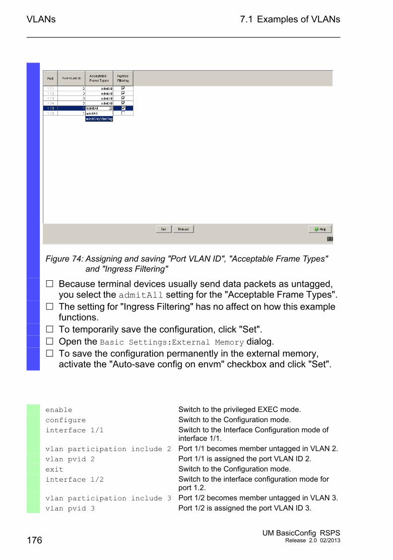
VLANs 7.1 Examples of VLANs
Figure 74: Assigning and saving "Port VLAN ID", "Acceptable Frame Types" and "Ingress Filtering"
Because terminal devices usually send data packets as untagged, you select the admitAll setting for the "Acceptable Frame Types".
The setting for "Ingress Filtering" has no affect on how this example functions.
To temporarily save the configuration, click "Set". Open the Basic Settings:External Memory dialog. To save the configuration permanently in the external memory,
activate the "Auto-save config on envm" checkbox and click "Set".
enable Switch to the privileged EXEC mode.configure Switch to the Configuration mode.interface 1/1 Switch to the Interface Configuration mode of
interface 1/1.vlan participation include 2 Port 1/1 becomes member untagged in VLAN 2.vlan pvid 2 Port 1/1 is assigned the port VLAN ID 2.exit Switch to the Configuration mode.interface 1/2 Switch to the interface configuration mode for
port 1.2.vlan participation include 3 Port 1/2 becomes member untagged in VLAN 3.vlan pvid 3 Port 1/2 is assigned the port VLAN ID 3.
176UM BasicConfig RSPS
Release 2.0 02/2013
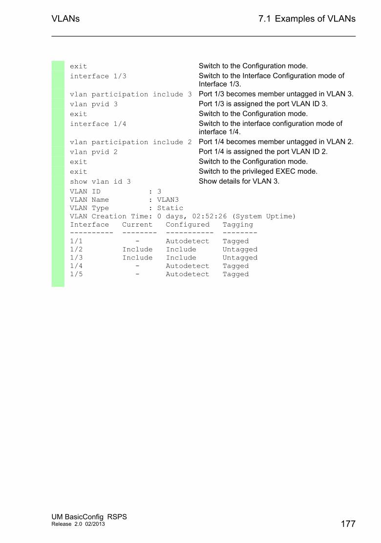
VLANs 7.1 Examples of VLANs
exit Switch to the Configuration mode.interface 1/3 Switch to the Interface Configuration mode of
Interface 1/3.vlan participation include 3 Port 1/3 becomes member untagged in VLAN 3.vlan pvid 3 Port 1/3 is assigned the port VLAN ID 3.exit Switch to the Configuration mode.interface 1/4 Switch to the interface configuration mode of
interface 1/4.vlan participation include 2 Port 1/4 becomes member untagged in VLAN 2.vlan pvid 2 Port 1/4 is assigned the port VLAN ID 2.exit Switch to the Configuration mode.exit Switch to the privileged EXEC mode.show vlan id 3 Show details for VLAN 3.VLAN ID : 3VLAN Name : VLAN3VLAN Type : StaticVLAN Creation Time: 0 days, 02:52:26 (System Uptime)Interface Current Configured Tagging---------- -------- ----------- --------1/1 - Autodetect Tagged1/2 Include Include Untagged1/3 Include Include Untagged1/4 - Autodetect Tagged1/5 - Autodetect Tagged
UM BasicConfig RSPSRelease 2.0 02/2013 177
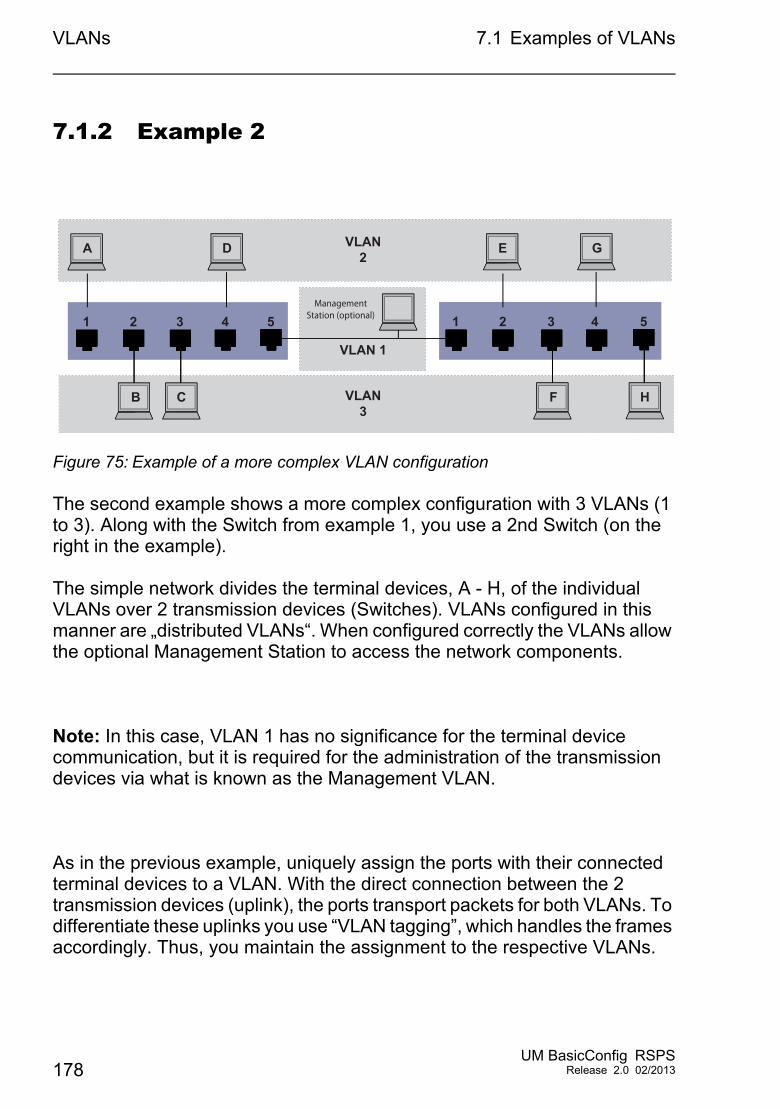
VLANs 7.1 Examples of VLANs
7.1.2 Example 2
Figure 75: Example of a more complex VLAN configuration
The second example shows a more complex configuration with 3 VLANs (1 to 3). Along with the Switch from example 1, you use a 2nd Switch (on the right in the example).
The simple network divides the terminal devices, A - H, of the individual VLANs over 2 transmission devices (Switches). VLANs configured in this manner are „distributed VLANs“. When configured correctly the VLANs allow the optional Management Station to access the network components.
Note: In this case, VLAN 1 has no significance for the terminal device communication, but it is required for the administration of the transmission devices via what is known as the Management VLAN.
As in the previous example, uniquely assign the ports with their connected terminal devices to a VLAN. With the direct connection between the 2 transmission devices (uplink), the ports transport packets for both VLANs. To differentiate these uplinks you use “VLAN tagging”, which handles the frames accordingly. Thus, you maintain the assignment to the respective VLANs.
1 32
VLAN2
VLAN3
A
B C
D
1 432
E
F H
G
4 5 5Management
Station (optional)
VLAN 1
178UM BasicConfig RSPS
Release 2.0 02/2013
VLANs 7.1 Examples of VLANs
Proceed as follows to perform the example configuration: Add Uplink Port 5 to the ingress and egress tables from example 1. Create new ingress and egress tables for the right switch, as described in
the first example.The egress table specifies on which ports the device sends the frames from this VLAN. T = with tag field (T = tagged, marked) U = without tag field (U = untagged, not marked)
In this example, the devices use tagged frames in the communication between the transmission devices (uplink), the ports differentiate the frames for different VLANs.
Terminal Port Port VLAN identifier (PVID)
A 1 2B 2 3C 3 3D 4 2Uplink 5 1
Table 14: Ingress table for device on left
Terminal Port Port VLAN identifier (PVID)
Uplink 1 1E 2 2F 3 3G 4 2H 5 3
Table 15: Ingress table for device on right
VLAN ID Port1 2 3 4 5
1 U
Table 16: Egress table for device on left
UM BasicConfig RSPSRelease 2.0 02/2013 179
VLANs 7.1 Examples of VLANs
The communication relationships here are as follows: terminal devices on ports 1 and 4 of the left device and terminal devices on ports 2 and 4 of the right device are members of VLAN 2 and can thus communicate with each other. The behavior is the same for the terminal devices on ports 2 and 3 of the left device and the terminal devices on ports 3 and 5 of the right device. These belong to VLAN 3.
The terminal devices “see” their respective part of the network. Participants outside this VLAN cannot be reached. The device also sends broadcast, multicast, and unicast packets with unknown (unlearned) destination addresses exclusively inside a VLAN.
Here, the devices use VLAN tagging (IEEE 801.1Q) within the VLAN with the ID 1 (Uplink). The letter T in the egress table of the ports indicates VLAN tagging.
The configuration of the example is the same for the device on the right. Proceed in the same way, using the ingress and egress tables created above to adapt the previously configured left device to the new environment.
2 U U T3 U U T
VLAN ID Port1 2 3 4 5
1 U2 T U U3 T U U
Table 17: Egress table for device on right
VLAN ID Port
Table 16: Egress table for device on left
180UM BasicConfig RSPS
Release 2.0 02/2013
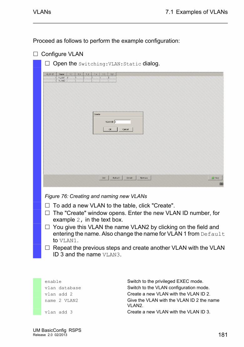
VLANs 7.1 Examples of VLANs
Proceed as follows to perform the example configuration:
Configure VLAN
Open the Switching:VLAN:Static dialog.
Figure 76: Creating and naming new VLANs
To add a new VLAN to the table, click "Create". The "Create" window opens. Enter the new VLAN ID number, for
example 2, in the text box. You give this VLAN the name VLAN2 by clicking on the field and
entering the name. Also change the name for VLAN 1 from Default to VLAN1.
Repeat the previous steps and create another VLAN with the VLAN ID 3 and the name VLAN3.
enable Switch to the privileged EXEC mode.vlan database Switch to the VLAN configuration mode.vlan add 2 Create a new VLAN with the VLAN ID 2.name 2 VLAN2 Give the VLAN with the VLAN ID 2 the name
VLAN2.vlan add 3 Create a new VLAN with the VLAN ID 3.
UM BasicConfig RSPSRelease 2.0 02/2013 181
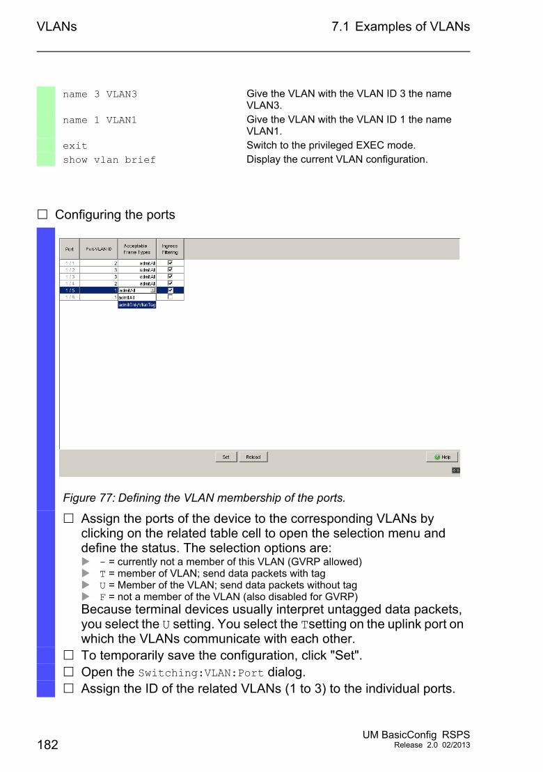
VLANs 7.1 Examples of VLANs
Configuring the ports
name 3 VLAN3 Give the VLAN with the VLAN ID 3 the name VLAN3.
name 1 VLAN1 Give the VLAN with the VLAN ID 1 the name VLAN1.
exit Switch to the privileged EXEC mode.show vlan brief Display the current VLAN configuration.
Figure 77: Defining the VLAN membership of the ports.
Assign the ports of the device to the corresponding VLANs by clicking on the related table cell to open the selection menu and define the status. The selection options are: - = currently not a member of this VLAN (GVRP allowed) T = member of VLAN; send data packets with tag U = Member of the VLAN; send data packets without tag F = not a member of the VLAN (also disabled for GVRP)Because terminal devices usually interpret untagged data packets, you select the U setting. You select the Tsetting on the uplink port on which the VLANs communicate with each other.
To temporarily save the configuration, click "Set". Open the Switching:VLAN:Port dialog. Assign the ID of the related VLANs (1 to 3) to the individual ports.
182UM BasicConfig RSPS
Release 2.0 02/2013
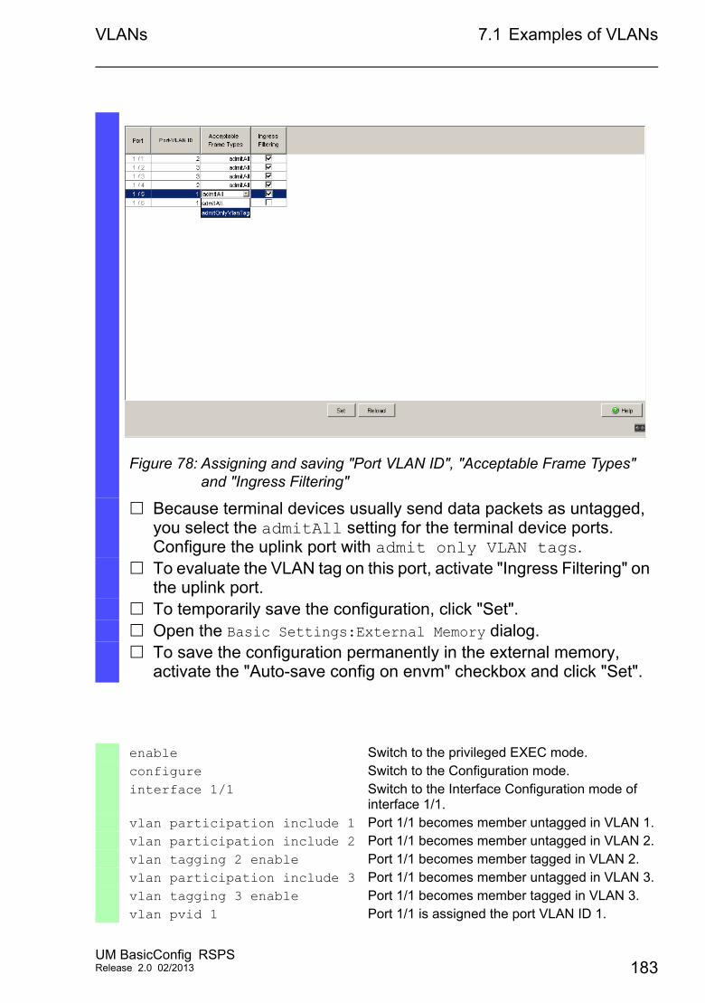
VLANs 7.1 Examples of VLANs
Figure 78: Assigning and saving "Port VLAN ID", "Acceptable Frame Types" and "Ingress Filtering"
Because terminal devices usually send data packets as untagged, you select the admitAll setting for the terminal device ports. Configure the uplink port with admit only VLAN tags.
To evaluate the VLAN tag on this port, activate "Ingress Filtering" on the uplink port.
To temporarily save the configuration, click "Set". Open the Basic Settings:External Memory dialog. To save the configuration permanently in the external memory,
activate the "Auto-save config on envm" checkbox and click "Set".
enable Switch to the privileged EXEC mode.configure Switch to the Configuration mode.interface 1/1 Switch to the Interface Configuration mode of
interface 1/1.vlan participation include 1 Port 1/1 becomes member untagged in VLAN 1.vlan participation include 2 Port 1/1 becomes member untagged in VLAN 2.vlan tagging 2 enable Port 1/1 becomes member tagged in VLAN 2.vlan participation include 3 Port 1/1 becomes member untagged in VLAN 3.vlan tagging 3 enable Port 1/1 becomes member tagged in VLAN 3.vlan pvid 1 Port 1/1 is assigned the port VLAN ID 1.
UM BasicConfig RSPSRelease 2.0 02/2013 183
VLANs 7.1 Examples of VLANs
For further information on VLANs, see the reference manual and the integrated help function in the program.
vlan ingressfilter Port 1/1 ingress filtering is activated.vlan acceptframe vlanonly Port 1/1 only forwards frames with a VLAN tag.exit Switch to the Configuration mode.interface 1/2 Switch to the interface configuration mode for
port 1.2.vlan participation include 2 Port 1/2 becomes member untagged in VLAN 2.vlan pvid 2 Port 1/2 is assigned the port VLAN ID 2.exit Switch to the Configuration mode.interface 1/3 Switch to the Interface Configuration mode of
Interface 1/3.vlan participation include 3 Port 1/3 becomes member untagged in VLAN 3.vlan pvid 3 Port 1/3 is assigned the port VLAN ID 3.exit Switch to the Configuration mode.interface 1/4 Switch to the interface configuration mode of
interface 1/4.vlan participation include 2 Port 1/4 becomes member untagged in VLAN 2.vlan pvid 2 Port 1/4 is assigned the port VLAN ID 2.exit Switch to the Configuration mode.interface 1/5 Switch to the interface configuration mode for port
1.5.vlan participation include 3 Port 1/5 becomes member untagged in VLAN 3.vlan pvid 3 Port 1/5 is assigned the port VLAN ID 3.exit Switch to the Configuration mode.exit Switch to the privileged EXEC mode.show vlan id 3 Show details for VLAN 3.VLAN ID......................3VLAN Name....................VLAN3VLAN Type....................StaticVLAN Creation Time...........0 days, 00:07:47 (System Uptime)VLAN Routing.................disabled
Interface Current Configured Tagging---------- -------- ----------- --------1/1 Include Include Tagged1/2 - Autodetect Untagged1/3 Include Include Untagged1/4 - Autodetect Untagged1/5 Include Include Untagged
184UM BasicConfig RSPS
Release 2.0 02/2013
VLANs 7.2 Creating a Voice VLAN
7.2 Creating a Voice VLAN
Use the Voice VLAN feature to separate voice and data traffic on a port, by VLAN and/or priority. A primary benefit of using Voice VLAN is to safeguard the sound quality of an IP phone when the data traffic on the port is high.
The device uses the source MAC address to identify and prioritize the voice data flow. Using a MAC address to identify devices helps prevent a rogue client from connecting to the same port causing the voice traffic to deteriorate.
Another benefit of the Voice VLAN feature is that a VoIP phone obtains a VLAN ID or priority information using LLDP-MED. As a result, the VoIP phone sends voice data as tagged, priority tagged or untagged depending on the Voice VLAN Interface configuration.
The following Voice VLAN interface modes are possible. The first 3 methods segregate and prioritize voice and data traffic. Traffic segregation results in an increased voice traffic quality during high traffic periods. Configuring the port to using the vlan mode allows the device to tag the
voice data coming from a VOIP phone with the user-defined voice VLAN ID. The device assigns regular data to the port default PVID.
Configuring the port to use the dot1p-priority mode allows the device to tag the data coming from a VOIP phone with VLAN 0 and the user-defined priority. The device assigns the default priority of the port to regular data.
Configure both the voice VLAN ID and the priority using the vlan/dot1p-priority mode. In this mode the VOIP phone sends voice data with the user-defined voice VLAN ID and priority information. The device assigns the default PVID and priority of the port to regular data.
When configured as untagged, the phone sends untagged frames. When configured as none, the phone uses its own configuration to send
voice traffic.
UM BasicConfig RSPSRelease 2.0 02/2013 185
VLANs 7.3 VLAN unaware mode
7.3 VLAN unaware mode
The VLAN-unaware function defines the operation of the device in a LAN segmented by VLANs. The device accepts packets and frames and processes them according to its inbound rules. Based on the IEEE 802.1Q specifications, the function governs how the device processes VLAN tagged frames or packets.
Use the VLAN aware mode to apply the user-defined VLAN topology configured by the network administrator. The device uses VLAN tagging in combination with the IP or Ethernet address when forwarding packets or frames. The device processes inbound and outbound frames or packets according to the defined rules. VLAN configuration is a manual process.
Use the VLAN unaware mode to forward traffic as received, without any modification. For example, the device transmits tagged packets when received as tagged and transmits untagged packets when received as untagged. Regardless of VLAN assignment mechanisms, the device assigns packets to VLAN ID 1 and to a multicast group, indicating that the packet flood domain is according to the VLAN.
186UM BasicConfig RSPS
Release 2.0 02/2013
Operation Diagnosis
8 Operation Diagnosis
The device provides you with the following diagnostic tools:
Sending traps Monitoring the device status Out-of-band signaling via signal contact Port status indication Event counter at port level Detecting non-matching duplex modes SFP status display Topology Discovery Detecting IP address conflicts Detecting loops Reports Monitoring data traffic on a port (port mirroring) Syslog Event log Cause and Action management during Selftest
UM BasicConfig RSPSRelease 2.0 02/2013 187
Operation Diagnosis 8.1 Sending Traps
8.1 Sending Traps
The device reports unusual events which occur during normal operation immediately to the management station. This is done by messages called traps that bypass the polling procedure ("Polling" means querying the data stations at regular intervals). Traps make it possible to react quickly to unusual events.
Examples of such events are:
a hardware reset changes to the configuration segmentation of a port …
The device sends traps to various hosts to increase the transmission reliability for the messages. The unacknowleged trap message consists of a packet containing information about an unusual event.
The device sends traps to those hosts entered in the trap destination table. The device allows you to configure the trap destination table with the management station via SNMP.
188UM BasicConfig RSPS
Release 2.0 02/2013
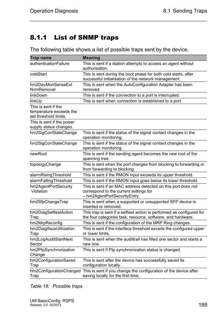
Operation Diagnosis 8.1 Sending Traps
8.1.1 List of SNMP traps
The following table shows a list of possible traps sent by the device.
Trap name MeaningauthenticationFailure This is sent if a station attempts to access an agent without
authorisation.coldStart This is sent during the boot phase for both cold starts, after
successful initialisation of the network management.hm2DevMonSenseExtNvmRemoval
This is sent when the AutoConfiguration Adapter has been removed.
linkDown This is sent if the connection to a port is interrupted.linkUp This is sent when connection is established to a port.This is sent if the temperature exceeds the set threshold limits.This is sent if the power supply status changes.hm2SigConStateChange This is sent if the status of the signal contact changes in the
operation monitoring.hm2SigConStateChange This is sent if the status of the signal contact changes in the
operation monitoring.newRoot This is sent if the sending agent becomes the new root of the
spanning tree.topologyChange This is sent when the port changes from blocking to forwarding or
from forwarding to blocking.alarmRisingThreshold This is sent if the RMON input exceeds its upper threshold.alarmFallingThreshold This is sent if the RMON input goes below its lower threshold.hm2AgentPortSecurity Violation
This is sent if an MAC address detected on this port does not correspond to the current settings for – hm2AgentPortSecurityEntry.
hm2SfpChangeTrap This is sent when a supported or unsupported SFP device is inserted or removed.
hm2DiagSelftestActionTrap
This trap is sent if a selftest action is performed as configured for the four categories task, resource, software, and hardware.
hm2MrpReconfig This is sent if the configuration of the MRP Ring changes.hm2DiagIfaceUtilizationTrap
This is sent if the interface threshold exceds the configured upper or lower limits.
hm2LogAuditStartNextSector
This is sent when the audittrail has filled one sector and starts a new one.
hm2PtpSynchronizationChange
This is sent if Ptp synchronization status is changed.
hm2ConfigurationSavedTrap
This is sent after the device has successfully saved its configuration locally.
hm2ConfigurationChangedTrap
This is sent if you change the configuration of the device after saving locally for the first time.
Table 18: Possible traps
UM BasicConfig RSPSRelease 2.0 02/2013 189
Operation Diagnosis 8.1 Sending Traps
8.1.2 Traps for configuration activity
After you save a configuration in memory, the device sends a hm2ConfigurationSavedTrap. This trap contains both the Non-Volatile Memory (NVM) and External Non-Volatile Memory (ENVM) state variables indicating whether the running configuration is in sync with the NVM, and with the ENVM. You also trigger this trap by copying a config file to the device replacing the active saved configuration.
Furthermore, the device sends a hm2ConfigurationChangedTrap, whenever you change the local configuration, indicating a mismatch between the running and saved configuration.
hm2PlatformStpInstanceLoopInconsistentStartTrap
This is sent if this port in this STP instance enters loop inconsistent state.
hm2PlatformStpInstanceLoopInconsistentEndTrap
This is sent if this port in this STP instance exits loop inconsistent state upon reception of a BPDU.
Trap name Meaning
Table 18: Possible traps (cont.)
190UM BasicConfig RSPS
Release 2.0 02/2013
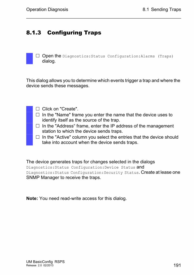
Operation Diagnosis 8.1 Sending Traps
8.1.3 Configuring Traps
This dialog allows you to determine which events trigger a trap and where the device sends these messages.
The device generates traps for changes selected in the dialogs Diagnostics:Status Configuration:Device Status and Diagnostics:Status Configuration:Security Status. Create at lease one SNMP Manager to receive the traps.
Note: You need read-write access for this dialog.
Open the Diagnostics:Status Configuration:Alarms (Traps) dialog.
Click on "Create". In the "Name" frame you enter the name that the device uses to
identify itself as the source of the trap. In the "Address“ frame, enter the IP address of the management
station to which the device sends traps. In the "Active" column you select the entries that the device should
take into account when the device sends traps.
UM BasicConfig RSPSRelease 2.0 02/2013 191
Operation Diagnosis 8.1 Sending Traps
8.1.4 ICMP Messaging
The device allows you to use the Internet Control Message Protocol (ICMP) for diagnostic applications, for example ping and trace route. The device also uses ICMP for time-to-live and discarding messages in which the device forwards an ICMP message back to the packet source device.
Use the ping network tool to test the path to a particular host across an IP network. The traceroute diagnostic tool displays paths and transit delays of packets across a network. The CLI handbook contains a description of the ping and traceroute tools.
Figure 79: Alarms dialog
192UM BasicConfig RSPS
Release 2.0 02/2013
Operation Diagnosis 8.2 Monitoring the Device Status
8.2 Monitoring the Device Status
The device status provides an overview of the overall condition of the device. Many process visualization systems record the device status for a device in order to present its condition in graphic form.
The device displays its current status as "Error" or "OK" in the "Device Status" frame. The device determines this status from the individual monitoring results.
The device enables you to:
signal the out-of-band device status via a signal contact
signal the device status by sending a trap when the device status changes
detect the device status in the Web-based interface in the Basic Settings:System dialog
query the device status in the Command Line Interface
The Diagnostics:Status Configuration:Device Status dialog allows you to configure the device to send a trap to the management station for the following events:
Incorrect supply voltage - at least one of the 2 supply voltages is not operating - the internal supply voltage is not operating
When the device is operating outside of the user-defined temperature threshold
Loss of the redundancy (in ring manager mode) The interruption of link connection(s). Configure at least one port for this
feature. In the Diagnostics:Status Configuration:Device Status "Propagate Connection Error" column, you define which ports the device signals if the connection is down .
The removal of the external memory. The configuration in the external memory is out-of-sync with the
configuration in the device.
Select the corresponding entries to decide which events the device status includes.
UM BasicConfig RSPSRelease 2.0 02/2013 193
Operation Diagnosis 8.2 Monitoring the Device Status
Note: With a non-redundant voltage supply, the device reports the absence of a supply voltage. To disable this message, feed the supply voltage over both inputs or ignore the monitoring.
8.2.1 Events which can be monitored
8.2.2 Configuring the Device Status
Name MeaningTemperature If the temperature exceeds or falls below the value specified.Connection error Enable this functioin to monitor every port link event in which the
"Propagate Connection Error" checkbox is active.ENVM removal Enable this functioin to monitor the presence of an external
memory storage device.ENVM not in Sync The device monitors sychronization between the device
configuration and the configuration stored on the ENVM.Ring redundancy Enable this function to monitor the connected ports for a possible
ring. Power Supply Select the "Propagate State" check box to monitor the power
supply.
Table 19: "Device Status" events
Select the Diagnostics:Status Configuration:Device Status dialog.
In the "Monitoring" field, you select the events you want to monitor. To monitor the temperature, you also set the temperature thresholds
in the Basic Settings:System dialog at the bottom of the "System Data" frame.
194UM BasicConfig RSPS
Release 2.0 02/2013
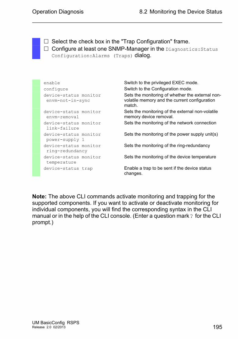
Operation Diagnosis 8.2 Monitoring the Device Status
Note: The above CLI commands activate monitoring and trapping for the supported components. If you want to activate or deactivate monitoring for individual components, you will find the corresponding syntax in the CLI manual or in the help of the CLI console. (Enter a question mark ? for the CLI prompt.)
Select the check box in the "Trap Configuration" frame. Configure at least one SNMP-Manager in the Diagnostics:Status
Configuration:Alarms (Traps) dialog.
enable Switch to the privileged EXEC mode.configure Switch to the Configuration mode.device-status monitor envm-not-in-sync
Sets the monitoring of whether the external non-volatile memory and the current configuration match.
device-status monitor envm-removal
Sets the monitoring of the external non-volatile memory device removal.
device-status monitor link-failure
Sets the monitoring of the network connection
device-status monitor power-supply 1
Sets the monitoring of the power supply unit(s)
device-status monitor ring-redundancy
Sets the monitoring of the ring-redundancy
device-status monitor temperature
Sets the monitoring of the device temperature
device-status trap Enable a trap to be sent if the device status changes.
UM BasicConfig RSPSRelease 2.0 02/2013 195
Operation Diagnosis 8.2 Monitoring the Device Status
8.2.3 Displaying the Device Status
Open the Basic Settings:System dialog.
Figure 80: Device status and alarm display1 - Start of the oldest existing device alarm2 - The symbol displays the security status3 - Start of the oldest existing security alarm4 - Cause of the oldest existing security alarm5 - Cause of the oldest existing device alarm6 - The symbol displays the device status
show device-status all In the EXEC Privilege mode, display the device status and the setting for the device status determination.
1 2 3
456
196UM BasicConfig RSPS
Release 2.0 02/2013
Operation Diagnosis 8.3 Security Status (DEVMON)
8.3 Security Status (DEVMON)
The Security Status provides an overview of the overall security of the device. Many processes aid in system visualization by recording the security status of the device and then presenting its condition in graphic form. The device displays the overall security status in the Basic Settings:System dialog, "Security Status" frame.
In the Diagnostics:Status Configuration:Security Status dialog the device displays its current status as Error or Ok in the "Security Status" frame. The device determines this status from the individual monitoring results.The device enables you to configure the following functions.
signal the device security status out-of-band via a signal contact
signal the device security status by sending a trap when the device status changes
detect the device security status in the Web-based interface in the Basic Settings:System dialog.
query the security status in the Command Line Interface.
The device monitors the following security statuses: Default passwords unchanged. Configured minimum password length. Password strength incorrect Password strength check inactive. Telnet Enabled. HTTP Enabled. Unsecure SNMP Configuration. SysMon active. Active Port without link. HiDiscovery Enabled. Config load from external NVM unsecure.
Select the events which the device includes in the security status alert by activating the "Monitor" radio button in the "Monitoring" frame.
UM BasicConfig RSPSRelease 2.0 02/2013 197
Operation Diagnosis 8.3 Security Status (DEVMON)
8.3.1 Events which can be monitored
Name MeaningDefault Password not changed
After installation change the passwords to increase security. The device monitors if the default passwords remain unchanged.hm2DevSecSensePasswordChange
Configured min. password length < 8
Create passwords more than 8 characters long to maintain a high security posture. When active the device monitors the "Minimum Password Length" setting.hm2DevSecSensePasswordMinLenght
Password strength not configured
The device monitors the settings located in the Security:User Management dialog for password strength requirements.hm2DevSecSensePasswordStrengthNotConfigured
Password strength check inactive
The device monitors the settings of the "Policy Check" control box, when inactive the device sends a trap. hm2DevSecSenseBypassPasswordStrength
Telnet Enabled The device monitors when you enable the Telnet function. hm2DevSecSenseTelnetEnabled
HTTP Enabled The device monitors when you enable the HTTP connection function. hm2DevSecSenseHTTPEnabled
Unsecure SNMP Configuration
The device monitors when you enable the SNMPv1 or v2 connection function. hm2DevSecSenseSnmpUnsecure
SysMon active The device monitors the System Monitor status. hm2DevSecSenseSysmonEnabled
External NVM Update possible
The device monitors the possibility to save configurations to the External non-volatile Memory. hm2DevSecSenseExtNvmUpdateEnabled
Active Port without link The device monitors the link status of active ports. hm2DevSecSenseNoLinkEnabled
HiDiscovery Enabled The device monitors when you enable the HiDiscovery read/write access function. hm2DevSecSenseHiDiscoveryEnabled
Config load from external NVM unsecure
The device monitors the security settings for loading the configuration from the external NVM. hm2DevSecSenseExtNvmConfigLoadUnsecure
Table 20: "Security Status" events
198UM BasicConfig RSPS
Release 2.0 02/2013
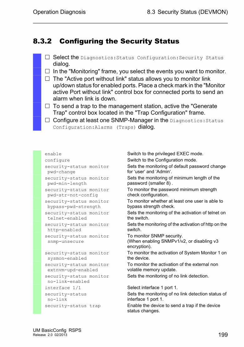
Operation Diagnosis 8.3 Security Status (DEVMON)
8.3.2 Configuring the Security Status
Select the Diagnostics:Status Configuration:Security Status dialog.
In the "Monitoring" frame, you select the events you want to monitor. The "Active port without link" status allows you to monitor link
up/down status for enabled ports. Place a check mark in the "Monitor active Port without link" control box for connected ports to send an alarm when link is down.
To send a trap to the management station, active the "Generate Trap" control box located in the "Trap Configuration" frame.
Configure at least one SNMP-Manager in the Diagnostics:Status Configuration:Alarms (Traps) dialog.
enable Switch to the privileged EXEC mode.configure Switch to the Configuration mode.security-status monitor pwd-change
Sets the monitoring of default password change for ‘user‘ and ‘Admin‘.
security-status monitor pwd-min-length
Sets the monitoring of minimum length of the password (smaller 8) .
security-status monitor pwd-str-not-config
To monitor the password minimum strength check configuration.
security-status monitor bypass-pwd-strength
To monitor whether at least one user is able to bypass strength check.
security-status monitor telnet-enabled
Sets the monitoring of the activation of telnet on the switch.
security-status monitor http-enabled
Sets the monitoring of the activation of http on the switch.
security-status monitor snmp-unsecure
To monitor SNMP security.(When enabling SNMPv1/v2, or disabling v3 encryption).
security-status monitor sysmon-enabled
To monitor the activation of System Monitor 1 on the device.
security-status monitor extnvm-upd-enabled
To monitor the activation of the external non volatile memory update.
security-status monitor no-link-enabled
Sets the monitoring of no link detection.
interface 1/1 Select interface 1 port 1.security-status no-link
Sets the monitoring of no link detection status of interface 1 port 1.
security-status trap Enable the device to send a trap if the device status changes.
UM BasicConfig RSPSRelease 2.0 02/2013 199
Operation Diagnosis 8.3 Security Status (DEVMON)
8.3.3 Displaying the Security Status
Open the Basic Settings:System dialog.
show security-status all In the EXEC Privilege mode, display the device status and the setting for the device status determination.
200UM BasicConfig RSPS
Release 2.0 02/2013
Operation Diagnosis 8.4 Out-of-band Signalling
8.4 Out-of-band Signalling
The device uses the signal contact to control external devices and monitor device functions. Function monitoring enables you to perform remote diagnostics.The device reports the operating status via a break in the potential-free signal contact (relay contact, closed circuit):The device monitors the following functions:
Incorrect supply voltage - at least one of the 2 supply voltages is not operating, - the internal supply voltage is not operating.
When the device is operating outside of the user-defined temperature threshold
Event in the ring redundancy:Loss of the redundancy (in ring manager mode). On delivery, there is no ring redundancy monitoring.
The interruption of link connection(s). Configure at least one port for this feature. In the "Propagate Connection Error" frame, you define which ports the device signals if the connection is down. On delivery, there is no link monitoring.
The removal of the external memory. The configuration on the external memory does not match that in the
device.
Select the corresponding entries to decide which events the device status includes.
Note: With a non-redundant voltage supply, the device reports the absence of a supply voltage. To disable this message, feed the supply voltage over both inputs or ignore the monitoring.
UM BasicConfig RSPSRelease 2.0 02/2013 201
Operation Diagnosis 8.4 Out-of-band Signalling
8.4.1 Controlling the Signal Contact
With this mode you control this signal contact remotely.
Application options:
Simulation of an error detected during SPS error monitoring
Remote control of a device via SNMP, such as switching on a camera
Open the Diagnostics:Status Configuration:Signal Contact dialog.
To activate the signal contact manually, you select the "Manual Setting" option in the Signal Contact Mode frame.
To open the signal contact, you select the "Opened" option in the Manual Setting frame.
To close the signal contact, you select the "Closed" option in the Manual Setting frame.
enable Switch to the privileged EXEC mode.configure Switch to the Configuration mode.signal-contact 1 mode manual Select the manual setting mode for signal contact
1.signal-contact 1 state open Open signal contact 1.signal-contact 1 state closed Close signal contact 1.
202UM BasicConfig RSPS
Release 2.0 02/2013
Operation Diagnosis 8.4 Out-of-band Signalling
8.4.2 Monitoring the Device Status via the Signal Contact
The "Device Status" option enables you, like in the function monitoring, to monitor the device status via the signal contact.
Configuring the operation monitoring Open the Diagnostics:Status Configuration:Signal Contact
dialog. Select the Monitoring Correct Operation option in the
"Signal Contact Mode" frame to use the signal contact to monitor the device functions.
Select the Monitoring option in the "Monitoring Correct Operation" frame for the events to be monitored.
You define the temperature thresholds for the temperature monitoring in the Basics Settings:System dialog.
enable Switch to the privileged EXEC mode.configure Switch to the Configuration mode.signal-contact 1 monitor envm-not-in-sync
Sets the monitoring of synchronization between the external non-volatile memory and the current configuration.
signal-contact 1 monitor envm-removal
Sets the monitoring of the external non-volatile memory device removal.
signal-contact 1 monitor link-failure
Sets the monitoring of the network connection
signal-contact 1 monitor power-supply
Sets the monitoring of the power supply
signal-contact 1 monitor ring-rundancy
Sets the monitoring of the ring-redundancy
signal-contact 1 monitor temperature
Sets the monitoring of the device temperature
signal-contact 1 monitor temperature
Sets the monitoring of the device temperature
signal-contact 1 trap Enables the device to send a trap the status of the operation monitoring changes.
no signal-contact 1 trap Disables a trap messaging.
UM BasicConfig RSPSRelease 2.0 02/2013 203
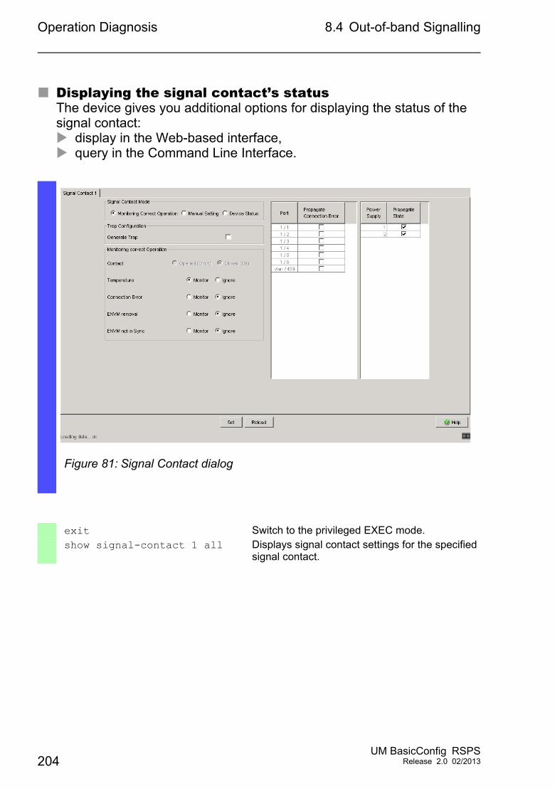
Operation Diagnosis 8.4 Out-of-band Signalling
Displaying the signal contact’s statusThe device gives you additional options for displaying the status of the signal contact: display in the Web-based interface, query in the Command Line Interface.
Figure 81: Signal Contact dialog
exit Switch to the privileged EXEC mode.show signal-contact 1 all Displays signal contact settings for the specified
signal contact.
204UM BasicConfig RSPS
Release 2.0 02/2013
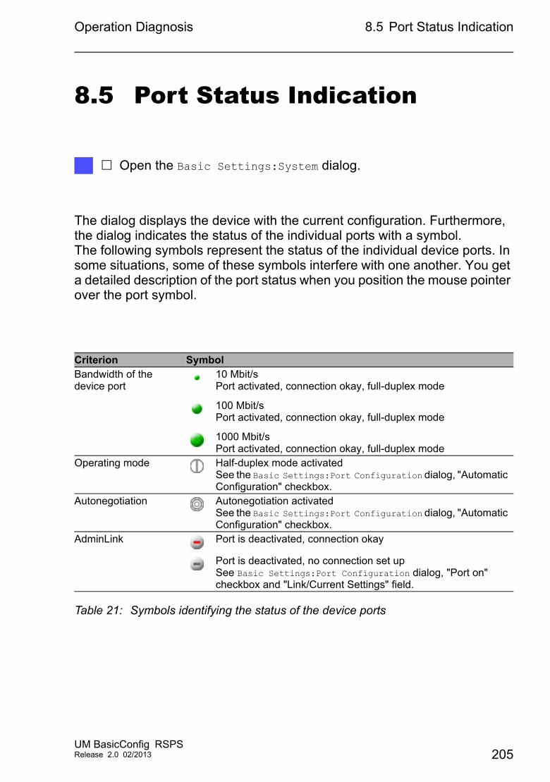
Operation Diagnosis 8.5 Port Status Indication
8.5 Port Status Indication
The dialog displays the device with the current configuration. Furthermore, the dialog indicates the status of the individual ports with a symbol. The following symbols represent the status of the individual device ports. In some situations, some of these symbols interfere with one another. You get a detailed description of the port status when you position the mouse pointer over the port symbol.
Open the Basic Settings:System dialog.
Criterion SymbolBandwidth of the device port
10 Mbit/sPort activated, connection okay, full-duplex mode
100 Mbit/sPort activated, connection okay, full-duplex mode
1000 Mbit/sPort activated, connection okay, full-duplex mode
Operating mode Half-duplex mode activatedSee the Basic Settings:Port Configuration dialog, "Automatic Configuration" checkbox.
Autonegotiation Autonegotiation activatedSee the Basic Settings:Port Configuration dialog, "Automatic Configuration" checkbox.
AdminLink Port is deactivated, connection okay
Port is deactivated, no connection set upSee Basic Settings:Port Configuration dialog, "Port on" checkbox and "Link/Current Settings" field.
Table 21: Symbols identifying the status of the device ports
UM BasicConfig RSPSRelease 2.0 02/2013 205
Operation Diagnosis 8.6 Event Counter at Port Level
8.6 Event Counter at Port Level
The port statistics table enables experienced network administrators to identify possible detected problems in the network.This table shows you the contents of various event counters. In the Basic Settings:Restart dialog, you can reset the event counters to zero using "Cold start" or "Reset port counters". The packet counters add up the events sent and the events received.The event counters may be obseverd by selecting the Diagnostics:Ports:Statistics Table dialog.
Counter Indication of known possible weaknessReceived fragments – Non-functioning controller of the connected device
– Electromagnetic interference in the transmission mediumCRC error – Non-functioning controller of the connected device
– Electromagnetic interference in the transmission medium– Inoperable component in the network
Collisions – Non-functioning controller of the connected device– Network over extended/lines too long– Collision or a detected fault with a data packet
Table 22: Examples indicating known weaknesses
To reset the counters, click on "Reset port counters" in the Basic Settings:Restart dialog.
To monitor the current status of the event counters, open the Diagnostics:Ports:Statistics Table dialog and click the "Reload" button.
206UM BasicConfig RSPS
Release 2.0 02/2013
Operation Diagnosis 8.6 Event Counter at Port Level
8.6.1 Detecting Non-matching Duplex Modes
Problems occur when 2 ports directly connected to each other have mismatching duplex modes. These problems are difficult to track down. The automatic detection and reporting of this situation has the benefit of recognizing mismatching duplex modes before problems occur.
This situation arises from an incorrect configuration, for example, if you deactivate the automatic configuration on the remote port.
A typical effect of this non-matching is that at a low data rate, the connection seems to be functioning, but at a higher bi-directional traffic level the local device records a lot of CRC errors, and the connection falls significantly below its nominal capacity.
The device allows you to detect this situation and report it to the network management station. In the process, the device evaluates the error counters of the port in the context of the port settings.
Possible causes of port error eventsThe following table lists the duplex operating modes for TX ports, with the possible fault events. The meanings of terms used in the table are as follows:
Collisions: In half-duplex mode, collisions mean normal operation. Duplex problem: Mismatching duplex modes. EMI: Electromagnetic interference. Network extension: The network extension is too great, or too many
cascading hubs. Collisions, late collisions: In full-duplex mode, no incremation of the
port counters for collisions or late collisions. CRC error: The device evaluates these errors as non-matching duplex
modes in the manual full duplex mode.
No. Automatic configuration
Current duplex mode
Detected error events (≥ 10 after link up)
Duplex modes Possible causes
1 On Half duplex None OK2 On Half duplex Collisions OK
Table 23: Evaluation of non-matching of the duplex mode
UM BasicConfig RSPSRelease 2.0 02/2013 207
Operation Diagnosis 8.6 Event Counter at Port Level
3 On Half duplex Late collisions Duplex problem detected
Duplex problem, EMI, network extension
4 On Half duplex CRC error OK EMI5 On Full duplex None OK6 On Full duplex Collisions OK EMI7 On Full duplex Late collisions OK EMI8 On Full duplex CRC error OK EMI9 Off Half duplex None OK10 Off Half duplex Collisions OK11 Off Half duplex Late collisions Duplex problem
detectedDuplex problem, EMI, network extension
12 Off Half duplex CRC error OK EMI13 Off Full duplex None OK14 Off Full duplex Collisions OK EMI15 Off Full duplex Late collisions OK EMI16 Off Full duplex CRC error Duplex problem
detectedDuplex problem, EMI
No. Automatic configuration
Current duplex mode
Detected error events (≥ 10 after link up)
Duplex modes Possible causes
Table 23: Evaluation of non-matching of the duplex mode (cont.)
208UM BasicConfig RSPS
Release 2.0 02/2013
Operation Diagnosis 8.7 Displaying the SFP Status
8.7 Displaying the SFP Status
The SFP status display allows you to look at the current SFP module connections and their properties. The properties include:
module type serial number of media module temperature in º C transmission power in mW receive power in mW
Open the Diagnostics:Ports:SFP dialog.
UM BasicConfig RSPSRelease 2.0 02/2013 209
Operation Diagnosis 8.8 Topology Discovery
8.8 Topology Discovery
IEEE 802.1AB defines the Link Layer Discovery Protocol (LLDP). LLDP allows the user to automatically detect the LAN network topology.
Devices with LLDP active
broadcast their connection and management information to neighboring devices on the shared LAN. Evaluation of the devices occur when the receiving device has its LLDP function active.
receive connection and management information from neighbor devices on the shared LAN, provided these adjacent devices also have LLDP active.
build a management-information database and object definitions for storing information about adjacent devices with LLDP active.
As the main element, the connection information contains an exact, unique identifier for the connection end point: MAC (Service Access Point). This is made up of a device identifier which is unique on the entire network and a unique port identifier for this device.Content of the connection and management-information:
Chassis identifier (its MAC address) Port identifier (its port-MAC address) Description of port System name System description Supported system capabilities System capabilities currently active Interface ID of the management address VLAN-ID of the port Auto-negotiation status at the port Medium, half/full duplex setting and port speed setting Information about the VLANs installed in the device (VLAN-ID and VLAN
name, irrespective of whether the port is a VLAN participant).
A network management station querys this information from devices that have LLDP active. This information allows the network management station to form a description of the network topology.
210UM BasicConfig RSPS
Release 2.0 02/2013
Operation Diagnosis 8.8 Topology Discovery
802.1d devices normally block the special multicast LLDP IEEE MAC address used for information exchange. Non-LLDP devices therefore discard LLDP packets. When positioning a non-LLDP capable device between 2 LLDP capable devices, the non-LLDP capable device prohibits information exchanges between the 2 LLDP capable devices.
The Management Information Base (MIB) for a device with LLDP capability holds the LLDP information in the lldp MIB and in the private hmLLDPInterfaceTable.
8.8.1 Displaying the Topology Discovery Results
To show the topology of the network:
If you use a port to connect several devices, for example via a hub, the table contains a line for each connected device.
Activating "Display FDB Entries" at the bottom of the table allows you to display devices without active LLDP support in the table. In this case, the device also includes information from its FDB (forwarding database).
If you connect the port to: devices with the topology discovery function active and devices with the topology discovery function inactive the topology table hides the devices without an active topology discovery.
When a port connects devices without an active topology discovery exclusively, the table contains a line for this port to represent the connected devices. This line contains the number of connected devices.
The FDB address table contains MAC addresses of devices that the topology table hides for the sake of clarity.
Open the "LLDP" tab in the Diagnostics:LLDP:Topology Discovery dialog.
UM BasicConfig RSPSRelease 2.0 02/2013 211
Operation Diagnosis 8.8 Topology Discovery
8.8.2 LLDP-Med
LLDP for Media Endpoint Devices (LLDP-MED) is an extension to LLDP that operates between endpoint devices. Endpoints include devices such as IP phones, or other Voice over IP (VoIP) devices or servers and network devices such as switches. It specifically provides support for VoIP applications. LLDP-MED provides this support using an additional set of common type-length-value (TLV) advertisement messages, for capabilities discovery, network policy, Power over Ethernet, inventory management and location information.
The device supports the following TLV messages: capabilities TLV
Allows LLDP-MED endpoints to determine the capabilities that the connected device supports and what capabilities the device has enabled.
Network policy TLVAllows both network connectivity devices and endpoints to advertise VLAN configurations and associated attributes for the specific application on that port. For example, the device notifies a phone of the VLAN number. The phone connects to a switch, obtain its VLAN number, and then starts communicating with the call control.
LLDP-MED provides the following functions: Network policy discovery, including VLAN ID, 802.1p priority and Diffserv
code point (DSCP) Device location and topology discovery based on LAN-level MAC/port
information Endpoint move detection notification, from network connectivity device to
the associated VoIP management application Extended device identification for inventory management Identification of endpoint network connectivity capabilities, for example,
multi-port IP Phone with embedded switch or bridge capability Application level interactions with the LLDP protocol elements to provide
timely startup of LLDP to support rapid availability of an Emergency Call Service
Applicability of LLDP-MED to Wireless LAN environments, support for Voice over Wireless LAN
212UM BasicConfig RSPS
Release 2.0 02/2013
Operation Diagnosis 8.9 Detecting Loops
8.9 Detecting Loops
Loops in the network, even temporary loops, cause connection interruptions or data losses. The automatic detection and reporting of this situation allows you to detect it faster and diagnose it more easily.
An incorrect configuration causes loops, for example, if you deactivate Spanning Tree.
The device allows you to detect the effects typically caused by loops and report this situation automatically to the network management station. You have the option here to specify the magnitude of the loop effects that trigger the device to send a report.
BPDU frames sent from the designated port and received on either a different port of the same device or the same port within a short time, is a typical effect of a loop.
UM BasicConfig RSPSRelease 2.0 02/2013 213
Operation Diagnosis 8.10 Reports
8.10 Reports
The following lists reports and buttons available for diagnostics:
System Log fileThe log file is an HTML file in which the device writes every important device-internal event.
Audit TrailLogs successful CLI commands and user comments. The file also includes SNMP logging.
Persistent Logging The device saves log entries in a file in the external memory, when present. These files are available after power down. The maximum size, maximum number of retainable files and the severity of logged events are configurable. After obtaining the user-defined maximum size or maximum number of retainable files, the device archives the entries and starts a new file. The device deletes the oldest file and renames the other files to maintain the configured number of files. To review these files use the CLI or copy them to an external server for future reference.
System informationThe system information is an HTML file containing the system-relevant data.
Download Support Information This button allows you to download system information as files in a ZIP archive.
In service situations, these reports provide the technician with the necessary information.
214UM BasicConfig RSPS
Release 2.0 02/2013
Operation Diagnosis 8.10 Reports
8.10.1 Global Settings
Using this dialog you enable or disable where the device sends reports. For example, to a Console, a Syslog Server, or a CLI connection. You also set at which severity level the device writes events into the reports.
The device buffers logged events in 2 separate storage areas so that the device keeps log entries for urgent events.Define the minimum severity for events that the device logs to the buffered storage area with a higher priority.
When you activate the logging of SNMP requests, the device logs the requests as events in the syslog. SNMP Get requests log a user requests for device configuration information. SNMP Set requests log device configuration events. Define the minimum level for events that the device logs in the syslog.
When active the device logs configuration changes, made using the CLI commands, to the audit trail. This feature is based on the IEEE 1686 standard for Substation Intelligent Electronic Devices.
Open the Diagnostics:Report:Global dialog. To send a report to the console configure the desired level in the
"Console Logging" frame "Severity" text box using the pull down menu.
To enable the operation, click On.
To send events to the buffer, configure the desired level in the "Buffered Logging" frame "Severity" text box using the pull down menu.
Activate “Log SNMP Get Request” if you want to send reading SNMP requests to the device as events to the syslog server.
Activate “Log SNMP Set Request” if you want to send writing SNMP requests to the device as events to the syslog server.
Choose the desired severity level for the get and set requests.
Open the Diagnostics:Report:Global dialog. To activate the function, in the "CLI Logging" frame, click On.
UM BasicConfig RSPSRelease 2.0 02/2013 215
Operation Diagnosis 8.10 Reports
The "Download JAR-File" button allows you to save a Java Applet of the graphic user interface (GUI) on your PC as a JAR file. This applet allows you have the option of administering the device, even if its HTTP server is switched off for security reasons.
The device creates the file name of the applet automatically in the format <device type><software version)>_<software revision of applet>.jar.
The "Download Support Information" button allows you to save the following system information data in one ZIP file on your PC: System log (systemlog.html) System information (systeminfo.html) Audit trail (audittrail.html) Support information (supportinfo.html) Running configuration (runningconfig.xml) Default configuration (defaultconfig.xml)
The device creates the file name of the support information automatically in the format <IP address>_<system name>.zip.
Click on "Download JAR-File". Select the directory in which you want to save the applet. Click “Save”.
Click on "Download Support Information". Select the directory in which you want to save the support
information. Click on "Save".
216UM BasicConfig RSPS
Release 2.0 02/2013
Operation Diagnosis 8.10 Reports
8.10.2 Syslog
The device enables you to send messages about important device-internal events to one or more syslog servers (up to 8). Additionally, you also include SNMP requests to the device as events in the syslog.
Note: To view the actual logged events, open the Diagnostics:Report:Audit Trail dialog or the Diagnostics:Report:System Log dialog.
Configure the following settings for read and write SNMP requests in the "SNMP Logging" frame:
Open the Diagnostics:Report:Syslog dialog. Activate the syslog function in the "Operation" frame. Click on “Create”. Enter the IP address of the syslog server, in the “IP Address”
column. Enter the UDP port on which the syslog server receives log entries,
in the "Port" column. Enter the minimum seriousness level an event must attain for the
device to send a log entry to this syslog server in the “Minimum Severity” column.
To enable the syslog server entry to which the device sends the logs, select the “Active” control box.
Select the Diagnostics:Report:Global dialog. Activate “Log SNMP Get Request” if you want to send reading
SNMP requests to the device as events to the syslog server. Activate “Log SNMP Set Request” if you want to send writing SNMP
requests to the device as events to the syslog server. Choose the desired severity level for the get and set requests.
UM BasicConfig RSPSRelease 2.0 02/2013 217
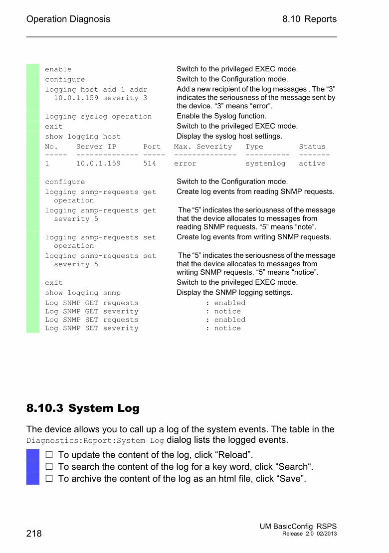
Operation Diagnosis 8.10 Reports
8.10.3 System Log
The device allows you to call up a log of the system events. The table in the Diagnostics:Report:System Log dialog lists the logged events.
enable Switch to the privileged EXEC mode.configure Switch to the Configuration mode.logging host add 1 addr 10.0.1.159 severity 3
Add a new recipient of the log messages . The “3” indicates the seriousness of the message sent by the device. “3” means “error”.
logging syslog operation Enable the Syslog function.exit Switch to the privileged EXEC mode.show logging host Display the syslog host settings.No. Server IP Port Max. Severity Type Status----- -------------- ----- -------------- ---------- -------1 10.0.1.159 514 error systemlog active
configure Switch to the Configuration mode.logging snmp-requests get operation
Create log events from reading SNMP requests.
logging snmp-requests get severity 5
The “5” indicates the seriousness of the message that the device allocates to messages from reading SNMP requests. “5” means “note”.
logging snmp-requests set operation
Create log events from writing SNMP requests.
logging snmp-requests set severity 5
The “5” indicates the seriousness of the message that the device allocates to messages from writing SNMP requests. “5” means “notice”.
exit Switch to the privileged EXEC mode.show logging snmp Display the SNMP logging settings.Log SNMP GET requests : enabled Log SNMP GET severity : notice Log SNMP SET requests : enabled Log SNMP SET severity : notice
To update the content of the log, click “Reload”. To search the content of the log for a key word, click “Search“. To archive the content of the log as an html file, click “Save”.
218UM BasicConfig RSPS
Release 2.0 02/2013
Operation Diagnosis 8.10 Reports
Note: You have the option to also send the logged events to one or more syslog servers.
8.10.4 Audit Trail
The Diagnostics:Report:Audit Trail dialog containssystem information and changes to the device configuration using CLI and SNMP. In the case of device configuration changes, the dialog displays Who changed What and When. To log changes to the device configuration, use the "SNMP Get Request" and "SNMP Set Request" functions located in the Diagnostics:Report:Global dialog.
The Diagnostics:Report:Syslog dialog allows you to configure up to 8 Syslog servers to which the device sends the Audit Trail.
The following list contains log events: changes to configuration parameters CLI commands except show commands automatic changes to the System Time watchdog events locking a user after several unsuccessful login attempts special CLI command 'logging audit-trail <string>' which logs the
comment user login, either locally or remote, via CLI manual, user-initiated, logout timed logout after a user-defined period of CLI inactivity file transfer operation including a Firmware Update configuration changes via HiDiscovery automatic configuration or firmware updates via the external memory blocked management access due to invalid login rebooting opening and closing SNMP over HTTPS tunnels detected power failures
UM BasicConfig RSPSRelease 2.0 02/2013 219
Operation Diagnosis 8.11 Network Analysis with TCPDump
8.11 Network Analysis with TCPDump
Tcpdump is a packet-sniffing UNIX utility used by network administrators to sniff and analyze traffic on a network. A couple of reasons for sniffing traffic on a network is to verify connectivity between hosts, or to analyze the traffic traversing the network.
Tcpdump on the device provides the possibility to decode or capture packets received and transmitted by the Management CPU. This function is available using the debug CLI command. Refer to the CLI Handbook for further information about the Tcpdump function.
220UM BasicConfig RSPS
Release 2.0 02/2013
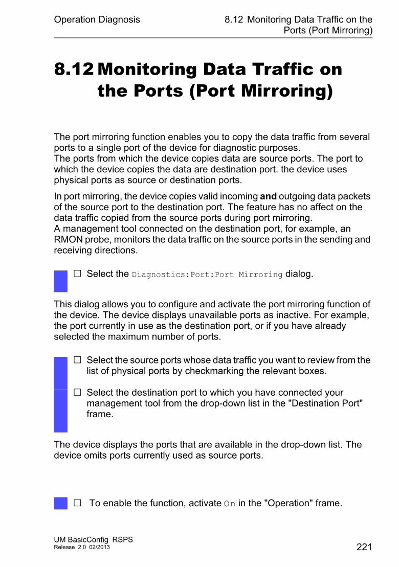
Operation Diagnosis 8.12 Monitoring Data Traffic on thePorts (Port Mirroring)
8.12 Monitoring Data Traffic on the Ports (Port Mirroring)
The port mirroring function enables you to copy the data traffic from several ports to a single port of the device for diagnostic purposes.The ports from which the device copies data are source ports. The port to which the device copies the data are destination port. the device uses physical ports as source or destination ports.
In port mirroring, the device copies valid incoming and outgoing data packets of the source port to the destination port. The feature has no affect on the data traffic copied from the source ports during port mirroring.A management tool connected on the destination port, for example, an RMON probe, monitors the data traffic on the source ports in the sending and receiving directions.
This dialog allows you to configure and activate the port mirroring function of the device. The device displays unavailable ports as inactive. For example, the port currently in use as the destination port, or if you have already selected the maximum number of ports.
The device displays the ports that are available in the drop-down list. The device omits ports currently used as source ports.
Select the Diagnostics:Port:Port Mirroring dialog.
Select the source ports whose data traffic you want to review from the list of physical ports by checkmarking the relevant boxes.
Select the destination port to which you have connected your management tool from the drop-down list in the "Destination Port" frame.
To enable the function, activate On in the "Operation" frame.
UM BasicConfig RSPSRelease 2.0 02/2013 221
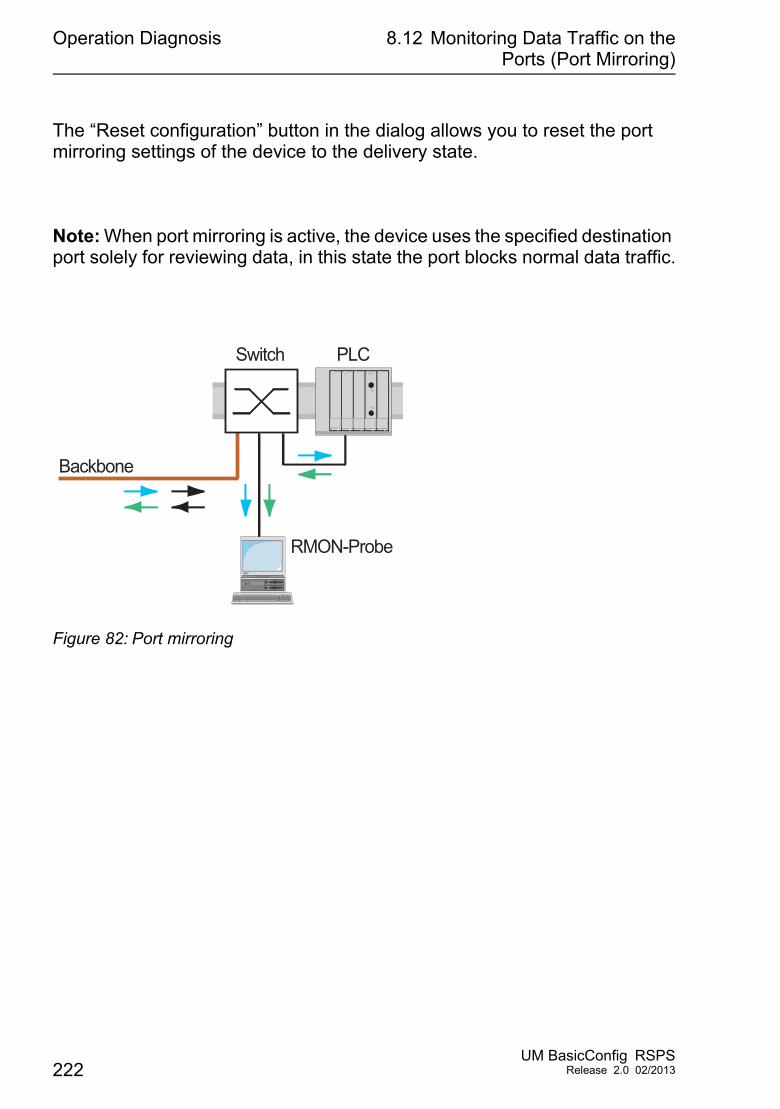
Operation Diagnosis 8.12 Monitoring Data Traffic on thePorts (Port Mirroring)
The “Reset configuration” button in the dialog allows you to reset the port mirroring settings of the device to the delivery state.
Note: When port mirroring is active, the device uses the specified destination port solely for reviewing data, in this state the port blocks normal data traffic.
Figure 82: Port mirroring
PLCSwitch
Backbone
RMON-Probe
222UM BasicConfig RSPS
Release 2.0 02/2013
Operation Diagnosis 8.13 Cause and Action managementduring Selftest
8.13 Cause and Action management during Selftest
The device checks its assets during the boot process and occasionally thereafter. The device checks system task availability or termination and the available amount of memory. Furthermore, the device checks for application functionality and if there is any hardware degradation in the chip set.
When the device detects a loss in integrity, the device responds to the degradation with a user-defined action. The following categories are available for configuration. "Task" - action to be taken when a task is unsuccessful. "Resources" - action to be taken due to the lack of resources. "Software" - action taken for loss of software integrity. For example, code
segment checksum or access violations. "Hardware" - action taken due to hardware degradation
Configure each category to produce an action when the device detects a loss in integrity. The following actions are available for configuration. log only - this action writes a message to the logging file. send trap - a trap will be sent to the management station. reboot - an error in the category, when activated, will cause the device
to reboot
Open the Diagnostics:System:Selftest dialog. Select the action to perform for a cause, in the "Action" column.
enable Switch to the privileged EXEC mode.configure Switch to the Configuration mode.selftest action task log-only
To send a message to the event log when a task is unsuccessful.
selftest action resource send-trap
To send a flag to the manamgement station when there is a lack of resources.
selftest action software send-trap
To send a flag to the manamgement station when there is a loss of software integrity.
selftest action hardware reboot
To reboot the device when hardware degradation occurs.
UM BasicConfig RSPSRelease 2.0 02/2013 223
Operation Diagnosis 8.13 Cause and Action managementduring Selftest
Disabling these functions lets you decrease the time required to reboot the device after a cold start. You find these options in the Diagnostics:System:Selftest dialog, located in the "Configuration" frame. "RAM Test" - to enable or disable the ramtest function during a cold start. "Activate SysMon1" - to enable or disable the System Monitor function
during a cold start. "Reload default config on error" - to enable or disable the reloading of the
standard device configuration if no readable configuration is available during a restart.
Note: Device access is in jeopardy when you disable the System Monitor 1, for example, misplacement or misconfiguration of the administrator password.
selftest ramtest Enable RAM selftest on cold start. no selftest ramtest Switch off the "ramtest“ function.selftest system-monitor Enable the "SysMon1“ function.no selftest system-monitor Switch off the "SysMon1“ function.show selftest action Show status of the actions to be taken in the event
of device degradation.show selftest settings Show ramtest and sysmon settings in event of a
cold start.
224UM BasicConfig RSPS
Release 2.0 02/2013

Advanced functions of the device
9 Advanced functions of the device
UM BasicConfig RSPSRelease 2.0 02/2013 225
Advanced functions of the device 9.1 Telnet Client
9.1 Telnet Client
The device supports a Telnet client that directly opens a connection to the Telnet server using TCP Port 23. The Telnet client allows you to configure the device using CLI commands.
For detailed information on CLI commands, review the “Command Line Interface” reference manual.
226UM BasicConfig RSPS
Release 2.0 02/2013

Setting up the Configuration Environ-ment
A Setting up the Configuration Environment
UM BasicConfig RSPSRelease 2.0 02/2013 227
Setting up the Configuration Environ-ment
A.1 Setting up a DHCP/BOOTPServer
A.1 Setting up a DHCP/BOOTP Server
On the product CD supplied with the device you will find the software for a DHCP server from the software development company IT-Consulting Dr. Herbert Hanewinkel. You can test the software for 30 calendar days from the date of the first installation, and then decide whether you want to purchase a license. To install the DHCP servers on your PC
put the product CD in the CD drive of your PC andunder Additional Software select “haneWIN DHCP-Server”.To carry out the installation, follow the installation assistant.
Start the DHCP Server program.
Figure 83: Start window of the DHCP server
228UM BasicConfig RSPS
Release 2.0 02/2013
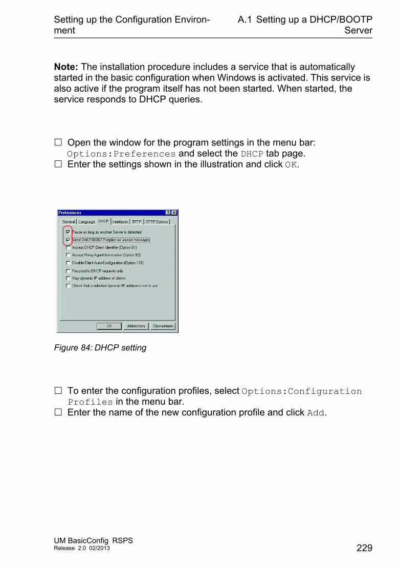
Setting up the Configuration Environ-ment
A.1 Setting up a DHCP/BOOTPServer
Note: The installation procedure includes a service that is automatically started in the basic configuration when Windows is activated. This service is also active if the program itself has not been started. When started, the service responds to DHCP queries.
Open the window for the program settings in the menu bar: Options:Preferences and select the DHCP tab page.
Enter the settings shown in the illustration and click OK.
Figure 84: DHCP setting
To enter the configuration profiles, select Options:Configuration Profiles in the menu bar.
Enter the name of the new configuration profile and click Add.
UM BasicConfig RSPSRelease 2.0 02/2013 229
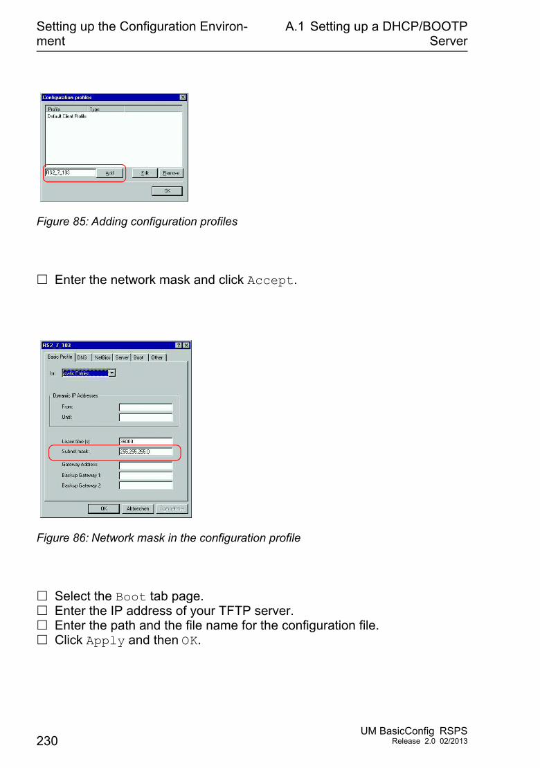
Setting up the Configuration Environ-ment
A.1 Setting up a DHCP/BOOTPServer
Figure 85: Adding configuration profiles
Enter the network mask and click Accept.
Figure 86: Network mask in the configuration profile
Select the Boot tab page. Enter the IP address of your TFTP server. Enter the path and the file name for the configuration file. Click Apply and then OK.
230UM BasicConfig RSPS
Release 2.0 02/2013
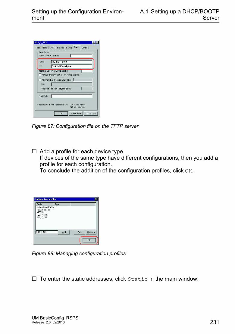
Setting up the Configuration Environ-ment
A.1 Setting up a DHCP/BOOTPServer
Figure 87: Configuration file on the TFTP server
Add a profile for each device type. If devices of the same type have different configurations, then you add a profile for each configuration.To conclude the addition of the configuration profiles, click OK.
Figure 88: Managing configuration profiles
To enter the static addresses, click Static in the main window.
UM BasicConfig RSPSRelease 2.0 02/2013 231
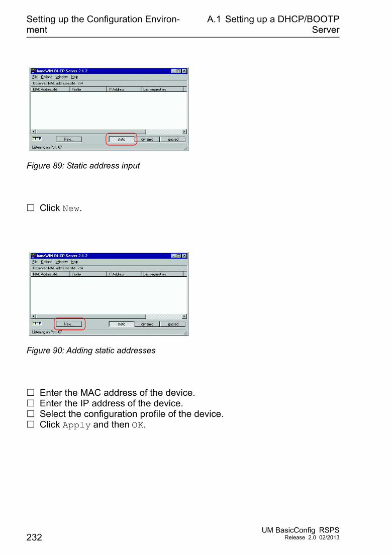
Setting up the Configuration Environ-ment
A.1 Setting up a DHCP/BOOTPServer
Figure 89: Static address input
Click New.
Figure 90: Adding static addresses
Enter the MAC address of the device. Enter the IP address of the device. Select the configuration profile of the device. Click Apply and then OK.
232UM BasicConfig RSPS
Release 2.0 02/2013
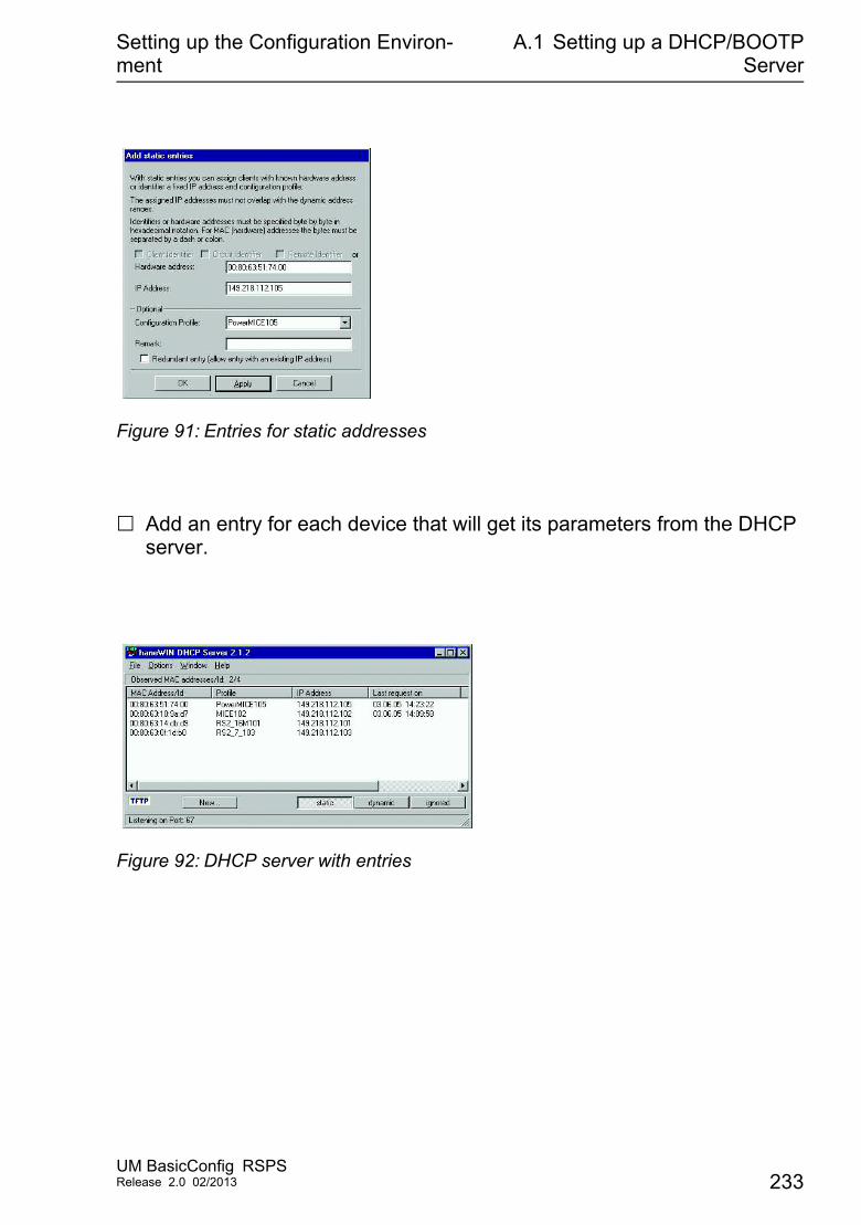
Setting up the Configuration Environ-ment
A.1 Setting up a DHCP/BOOTPServer
Figure 91: Entries for static addresses
Add an entry for each device that will get its parameters from the DHCP server.
Figure 92: DHCP server with entries
UM BasicConfig RSPSRelease 2.0 02/2013 233

Setting up the Configuration Environ-ment
A.1 Setting up a DHCP/BOOTPServer
234UM BasicConfig RSPS
Release 2.0 02/2013

General Information
B General Information
UM BasicConfig RSPSRelease 2.0 02/2013 235
General Information B.1 Management Information Base(MIB)
B.1 Management Information Base (MIB)
The Management Information Base (MIB) is designed in the form of an abstract tree structure.The branching points are the object classes. The "leaves" of the MIB are called generic object classes.If this is required for unique identification, the generic object classes are instantiated, i.e. the abstract structure is mapped onto reality, by specifying the port or the source address.Values (integers, time ticks, counters or octet strings) are assigned to these instances; these values can be read and, in some cases, modified. The object description or object ID (OID) identifies the object class. The subidentifier (SID) is used to instantiate them.
Example:The generic object classhm2PSState (OID = 1.3.6.1.4.1.248.11.11.1.1.1.1.2)is the description of the abstract information "power supply status". However, it is not possible to read any information from this, as the system does not know which power supply is meant.Specifying the subidentifier (2) maps this abstract information onto reality (instantiates it), thus indicating the operating status of power supply 2. A value is assigned to this instance and can then be read. The instance "get 1.3.6.1.4.1.248.11.11.1.1.1.1.2.1“ returns the response "1", which means that the power supply is ready for operation.
Definition of the syntax terms used:Integer An integer in the range -231 - 231-1IP Address xxx.xxx.xxx.xxx
(xxx = integer in the range 0-255)MAC Address 12-digit hexadecimal number in accordance with ISO/IEC 8802-3Object identifier x.x.x.x… (e.g. 1.3.6.1.1.4.1.248…)Octet string ASCII character stringPSID Power supply identifier
(number of the power supply unit)
236UM BasicConfig RSPS
Release 2.0 02/2013
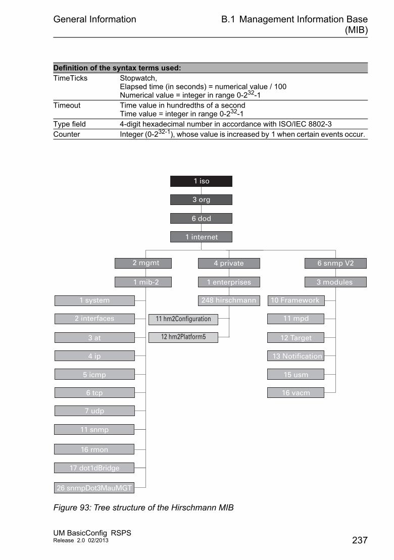
General Information B.1 Management Information Base(MIB)
Figure 93: Tree structure of the Hirschmann MIB
TimeTicks Stopwatch, Elapsed time (in seconds) = numerical value / 100Numerical value = integer in range 0-232-1
Timeout Time value in hundredths of a secondTime value = integer in range 0-232-1
Type field 4-digit hexadecimal number in accordance with ISO/IEC 8802-3Counter Integer (0-232-1), whose value is increased by 1 when certain events occur.
Definition of the syntax terms used:
1 internet
1 iso
3 org
6 dod
2 mgmt
1 enterprises
248 hirschmann
4 private
3 modules
10 Framework
6 snmp V2
1 mib-2
4 ip
2 interfaces
1 system
5 icmp
6 tcp
7 udp
16 rmon
11 snmp
26 snmpDot3MauMGT
17 dot1dBridge
11 hm2Configuration
12 hm2Platform53 at
13 Notification
11 mpd
15 usm
16 vacm
12 Target
UM BasicConfig RSPSRelease 2.0 02/2013 237

General Information B.1 Management Information Base(MIB)
A description of the MIB can be found on the product CD provided with the device.
238UM BasicConfig RSPS
Release 2.0 02/2013
General Information B.2 Abbreviations used
B.2 Abbreviations used
ACA31 AutoConfiguration AdapterACL Access Control ListBOOTP Bootstrap ProtocolCLI Command Line InterfaceDHCP Dynamic Host Configuration ProtocolFDB Forwarding DatabaseGUI Graphical User InterfaceHTTP Hypertext Transfer ProtocolHTTPS Hypertext Transfer Protocol SecureICMP Internet Control Message ProtocolIEEE Institute of Electrical and Electronics EngineersIGMP Internet Group Management ProtocolIP Internet ProtocolLED Light Emitting DiodeLLDP Link Layer Discovery ProtocolF/O Optical FiberMAC Media Access ControlMIB Management Information BaseMSTP Multiple Spanning Tree ProtocolNMS Network Management SystemNTP Network Time ProtocolPC Personal ComputerPTP Precision Time ProtocolQoS Quality of ServiceRFC Request For CommentRM Redundancy ManagerRSTP Rapid Spanning Tree ProtocolSCP Secure CopySFP Small Form-factor PluggableSFTP SSH File Transfer ProtocolSNMP Simple Network Management ProtocolSNTP Simple Network Time ProtocolTCP Transmission Control ProtocolTFTP Trivial File Transfer ProtocolTP Twisted PairUDP User Datagramm ProtocolURL Uniform Resource LocatorUTC Coordinated Universal TimeVLAN Virtual Local Area Network
UM BasicConfig RSPSRelease 2.0 02/2013 239

General Information B.3 Technical Data
B.3 Technical Data
You will find the technical data in the document “GUI Reference Manual”.
240UM BasicConfig RSPS
Release 2.0 02/2013

General Information B.4 Maintenance
B.4 Maintenance
Hirschmann is continually working to improve and develop our software. You should regularly check whether there is a new version of the software that provides you with additional benefits. You will find software information and downloads on the product pages of the Hirschmann website.
UM BasicConfig RSPSRelease 2.0 02/2013 241
General Information B.5 Readers’ Comments
B.5 Readers’ Comments
What is your opinion of this manual? We are constantly striving to provide as comprehensive a description of our product as possible, as well as important information to assist you in the operation of this product. Your comments and suggestions help us to further improve the quality of our documentation.
Your assessment of this manual:
Did you discover any errors in this manual?If so, on what page?
Very Good
Good Satisfactory Mediocre Poor
Precise description O O O O OReadability O O O O OUnderstandability O O O O OExamples O O O O OStructure O O O O OComprehensive O O O O OGraphics O O O O ODrawings O O O O OTables O O O O O
242UM BasicConfig RSPS
Release 2.0 02/2013

General Information B.5 Readers’ Comments
Suggestions for improvement and additional information:
General comments:
Sender:
Dear User,
Please fill out and return this page
as a fax to the number +49 (0)7127/14-1600 or per mail to
Hirschmann Automation and Control GmbHDepartment 01RD-NTStuttgarter Str. 45-5172654 Neckartenzlingen
Company / Department:
Name / Telephone number:
Street:
Zip code / City:
E-mail:
Date / Signature:
UM BasicConfig RSPSRelease 2.0 02/2013 243

General Information B.5 Readers’ Comments
244UM BasicConfig RSPS
Release 2.0 02/2013
Index
C Index
AAF 158Aging time 142Alarm 191Alarm messages 188APNIC 36ARIN 36ARP 40Assured Forwarding 158Authorization profiles 67
BBandwidth 167Best Master Clock algorithm 128BOOTP 35, 50Boundary clock (PTP) 127
CCD-ROM 228Classless Inter-Domain Routing 40Class Selector 158Closed circuit 201Command Line Interface 19Configuration changes 188Configuration file 50
DDaylight saving time 116Delay measurement (PTP) 129Delay (PTP) 129Destination table 188Device Status 193DHCP 35DHCP client 50DHCP server 115, 121, 228Differentiated services 158DiffServ 153DiffServ Codepoint 158DSCP 153, 158, 163
EEF 158Event Log 218Expedited Forwarding 158
FFAQ 247First installation 35Flow control 167
GGateway 37, 44Generic object classes 236Grandmaster (PTP) 128
HHaneWin 228Hardware reset 188HiDiscovery 45HiView 9HiVision 51Host address 37
IIANA 36IEEE MAC Address 211IGMP snooping 141, 142Industrial HiVision 10Installation (GUI) 17Instantiation 236IP Address 36, 43, 50IP header 153, 157, 158ISO/OSI layer model 40
JJava Runtime Environment 17
LLACNIC 36Leave message 142Link monitoring 193, 201Login window 18
MMAC address filter 134MAC destination address 40Memory (RAM) 87Message 188Multicast 142
NNetmask 37, 44Network Management 51Non-volatile memory (NVM) 87NVM (non-volatile memory) 87
OObject classes 236Object description 236
UM BasicConfig RSPSRelease 2.0 02/2013 245
Index
Object ID 236OpenSSH Suite 27Operation monitoring 201Ordinary clock (PTP) 127
PPassword 24, 28, 31PHB 158Polling 188Port Mirroring 221Port Priority 162Precedence 158Priority 156Priority Tagged Frames 156PTP 113PTP domain 130PuTTY 20
QQoS 154Query 142Queue 159
RRAM (memory) 87Real time 152Redundancy 9Reference time source 114, 121, 128Relay contact 201Remote diagnostics 201Report 214Report message 142RIPE NCC 36RMON probe 221Router 37
SSecure Shell 20, 25Secure Shell 19Security Status 197Segmentation 188Service 214Setting the time 114SFP module 209Signal contact 201SNMP 16, 188SNMPv1/v2 80SNTP 113SSH 19, 20, 25Starting the graphical user interface (GUI) 18Store-and-forward 134Strict Priority 159Subidentifier 236Subnet 44
Symbol 11System Monitor 33System Name 50System requirements (GUI) 17
TTechnical Questions 247ToS 153, 157, 158Traffic class 159, 162Traffic Shaping 165Training Courses 247Transmission reliability 188Transparent clock (PTP) 127Trap 188, 191Trap Destination Table 188Type of Service 157
UUpdate 33User name 24, 28, 31
VVideo 159VLAN 171VLAN priority 161VLAN tag 171VoIP 159VT100 30V.24 19, 29
WWeighted Fair Queuing 159Weighted Round Robin 159
246UM BasicConfig RSPS
Release 2.0 02/2013

Further Support
D Further Support
Technical QuestionsFor technical questions, please contact any Hirschmann dealer in your area or Hirschmann directly.
You will find the addresses of our partners on the Internet athttp://www.hirschmann.com
Contact our support athttps://hirschmann-support.belden.eu.com
You can contact us
in the EMEA region at Tel.: +49 (0)1805 14-1538 E-mail: [email protected]
in the America region at Tel.: +1 (717) 217-2270 E-mail: [email protected]
in the Asia-Pacific region at Tel.: +65 6854 9860 E-mail: [email protected]
Hirschmann Competence CenterThe Hirschmann Competence Center is ahead of its competitors:
Consulting incorporates comprehensive technical advice, from system evaluation through network planning to project planning.
Training offers you an introduction to the basics, product briefing and user training with certification.The current technology and product training courses can be found at http://www.hicomcenter.com
Support ranges from the first installation through the standby service to maintenance concepts.
UM BasicConfig RSPSRelease 2.0 02/2013 247

Further Support
With the Hirschmann Competence Center, you have decided against making any compromises. Our client-customized package leaves you free to choose the service components you want to use.Internet: http://www.hicomcenter.com
248UM BasicConfig RSPS
Release 2.0 02/2013

Further Support
UM BasicConfig RSPSRelease 2.0 02/2013 249