Embed Size (px)
Citation preview

Basic - L2ERelease 3.1 06/07
Technical [email protected]
User ManualBasic Configuration Industrial ETHERNET Gigabit Switch RS20/RS30/RS40, MS20/MS30,
The naming of copyrighted trademarks in this manual, even when not specially indicated, should not be taken to mean that these names may be considered as free in the sense of the trademark and tradename protection law and hence that they may be freely used by anyone.
© 2007 Hirschmann Automation and Control GmbH
Manuals and software are protected by copyright. All rights reserved. The copying, reproduction, translation, conversion into any electronic medium or machine scannable form is not permitted, either in whole or in part. An exception is the preparation of a backup copy of the software for your own use. For devices with embedded software, the end-user license agreement on the enclosed CD applies.
The performance features described here are binding only if they have been expressly guaranteed in the contract. This publication has been created by Hirschmann Automation and Control GmbH according to the best of our knowledge. Hirschmann reserves the right to change the contents of this manual without prior notice. Hirschmann can give no guarantee in respect of the correctness or accuracy of the details in this publication.
Hirschmann can accept no responsibility for damages, resulting from the use of the network components or the associated operating software. In addition, we refer to the conditions of use specified in the license contract.
Printed in Germany (9.7.07)
Hirschmann Automation and Control GmbHStuttgarter Straße 45-5172654 NeckartenzlingenTel. +49 1805 141538 -01-0607
Contents
Contents
Contents 3
About this Manual 9
Key 11
Introduction 13
1 Access to the user interfaces 15
1.1 System monitor 16
1.2 Command Line Interface 19
1.3 Web based Interface 22
2 Entering the IP parameters 25
2.1 Basics IP parameter 272.1.1 IP address (version 4) 272.1.2 Network mask 282.1.3 Example of how the network mask is used 30
2.2 Entering the IP parameters via CLI 32
2.3 Entering the IP parameters via HiDiscovery 35
2.4 Loading the system configuration from the ACA 37
2.5 System configuration via BOOTP 39
2.6 System configuration via DHCP 43
2.7 System Configuration via DHCP Option 82 46
2.8 System configuration via the Web-based Interface 47
2.9 Faulty Device Replacement 49
Basic - L2ERelease 3.1 06/07 3
Contents
3 Loading/saving settings 51
3.1 Loading settings 523.1.1 Loading from the local non-volatile memory 533.1.2 Loading from the AutoConfiguration Adapter 533.1.3 Loading from a file 543.1.4 Resetting the configuration to the state on delivery 56
3.2 Saving settings 573.2.1 Saving Locally (and on the ACA) 573.2.2 Saving into a file on URL 583.2.3 Saving into a binary file on the PC 593.2.4 Saving as script on the PC 59
4 Loading Software Updates 61
4.1 Loading the Software from the ACA 634.1.1 Swapping the software available 634.1.2 Starting the software 654.1.3 Performing a cold start 65
4.2 Loading the Software from the tftp Server 66
4.3 Loading Software via file selector 68
5 Configuring ports 69
6 Protection from unauthorized access 73
6.1 Password for SNMP access 746.1.1 Description Password for SNMP access 746.1.2 Entering password for SNMP access 75
6.2 Setting Telnet/Web access 796.2.1 Description Telnet/Web access 796.2.2 Description Web access 796.2.3 Enabling/disabling Telnet/Web access 80
6.3 Disabling HiDiscovery function 816.3.1 Description HiDiscovery protocol 816.3.2 Disabling HiDiscovery function 82
6.4 Port access control 836.4.1 Description port access control 836.4.2 Defining port access control 84
4Basic - L2E
Release 3.1 06/07
Contents
7 Synchronizing the System Time of the Network 87
7.1 Entering the Time 88
7.2 SNTP 907.2.1 Descripton SNTP 907.2.2 Preparing the SNTP configuration 917.2.3 Configuring SNTP 92
7.3 Precison Time Protocol 957.3.1 Funtion description PTP 957.3.2 Preparing the PTP configuration 987.3.3 Configuring PTP 99
7.4 Interaction PTP and SNTP 102
8 Traffic control 105
8.1 Directed frame forwarding 1068.1.1 Store-and-forward 1068.1.2 Multi-address capability 1068.1.3 Aging of learned addresses 1078.1.4 Entering static address entries 1088.1.5 Disabling the specific packet distribution 109
8.2 Multicast application 1108.2.1 Description multicast application 1108.2.2 Example of a multicast application 1118.2.3 Description IGMP snooping 1128.2.4 Setting multicast applications 112
8.3 Rate Limiter 1168.3.1 Description Rate Limiter 1168.3.2 Setting Rate Limiter for RS20/RS30/40,
MS20/30, MACH 1000 116
8.4 Prioritization 1198.4.1 Description Prioritization 1198.4.2 Tagging 1198.4.3 Handling of priority classes 1218.4.4 Setting Prioritization 122
8.5 Flow control 1248.5.1 Description Flow control 1248.5.2 Setting flow control 125
Basic - L2ERelease 3.1 06/07 5
Contents
8.6 VLANs 1268.6.1 Description VLANs 1268.6.2 Configuring VLANs 1298.6.3 Setting up VLANs 1318.6.4 Displaying the VLAN configuration 1318.6.5 Deleting the VLAN settings 1328.6.6 Example of a simple VLAN 133
9 Operation Diagnostics 141
9.1 Sending traps 1429.1.1 SNMP trap listing 1439.1.2 SNMP traps when booting 1449.1.3 Configuring traps 144
9.2 Monitoring Device Status 147
9.3 Out-of-band signaling 1509.3.1 Manual setting the signal contact 1519.3.2 Monitoring correct operation via the signal contact 1529.3.3 Monitoring the Device Status with a signal contact 153
9.4 Port status indication 154
9.5 Event counter on port level 156
9.6 Displaying the SFP Status 158
9.7 Topology discovery 1599.7.1 Description Topology discovery 1599.7.2 Displaying the topology discovery 161
9.8 IP Address Conflict Detection 1639.8.1 Description of IP address conflicts 1639.8.2 Configuring ACD 1649.8.3 Displaying ACD 164
9.9 Reports 166
9.10 Monitoring port traffic (port mirroring) 167
Apendix A:Setting up the configuration environment 169
A.1 Setting up DHCP/BOOTP Server 170
A.2 Setting up DHCP Server Option 82 176
6Basic - L2E
Release 3.1 06/07
Contents
A.3 tftp server for software updates 181A.3.1 Setting up the tftp process 182A.3.2 Software access rights 185
Appendix B:General Information 187
B.1 Hirschmann Competence 188
B.2 FAQ 189
B.3 Management Information BASE MIB 190
B.4 Used abbreviations 193
B.5 List of RFC's 194
B.6 Based IEEE standards 196
B.7 Technical Data 197
B.8 Copyright of integrated software 198B.8.1 Bouncy Castle Crypto APIs (Java) 198B.8.2 LVL7 Systems, Inc. 198
B.9 Reader's comments 199
Appendix C:Index 201
Basic - L2ERelease 3.1 06/07 7

Contents
8Basic - L2E
Release 3.1 06/07
About this Manual
About this Manual
The “Basic Configuration” user manual contains all the information you need to start operating the switch. It takes you step by step from the first startup operation through to the basic settings for operation in your environment.
The following thematic sequence has proven itself in practice:
D Set up device access for operation by entering the IP parameters
D Check the status of the software and update it if necessary
D Load/Save the configuration
D Configure the ports
D Set up protection from unauthorized access
D Optimize the data transmission with network load control
D Synchronize system time in the network
D Function diagnosis
The “Installation” user manual contains a device description, safety instructions, a description of the display, and all the other information that you need to install the device before you begin with the configuration of the device.
The “Redundancy Configuration” user manual contains all the information you need to select a suitable redundancy procedure and configure it.
The “Industrial Protocols” user manual describes how the Switch is connected by means of a communication protocol commonly used in the industry, such as EtherNet/IP or PROFINET.
You will find detailed descriptions of how to operate the individual functions in the “Web-based Interface” and “Command Line Interface” reference manuals.
If you use Network Management Software HiVision you have further opportunities to:
D have an event logbook.
Basic - L2ERelease 3.1 06/07 9

About this Manual
D configure the „System Location“ and „System Name“.D configure the network address range and SNMP parameters.D save the configuration on the Switch.D simultaneous configuration of several Switches.D configure the relevant ports to be displayed red if there is no link state.
10Basic - L2E
Release 3.1 06/07
Key
Key
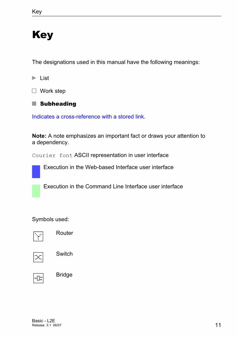
The designations used in this manual have the following meanings:
D List
V Work step
U Subheading
Indicates a cross-reference with a stored link.
Note: A note emphasizes an important fact or draws your attention to a dependency.
Courier font ASCII representation in user interface
Symbols used:
Execution in the Web-based Interface user interface
Execution in the Command Line Interface user interface
Router
Switch
Bridge
Basic - L2ERelease 3.1 06/07 11

Key
Hub
A random computer
Configuration computer
Server
12Basic - L2E
Release 3.1 06/07

Introduction
Introduction
The Switch has been developed for practical application in a harsh industrial environment. Accordingly, the installation process has been kept simple. Thanks to the selected default settings, you only have to enter a few settings before starting to operate the Switch.
Basic - L2ERelease 3.1 06/07 13

Introduction
14Basic - L2E
Release 3.1 06/07
Access to the user interfaces
1 Access to the user interfaces
The Switch has three user interfaces, which you can access via different interfaces:
D System monitor via the V.24 interface (out-of-band)
D Command Line Interface (CLI) via the V.24 connection (out-of-band) and Telnet (in-band)
D Web-based interface via Ethernet (in-band)
Basic - L2ERelease 3.1 06/07 15
Access to the user interfaces 1.1 System monitor
1.1 System monitor
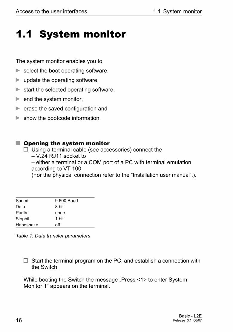
The system monitor enables you to
D select the boot operating software,
D update the operating software,
D start the selected operating software,
D end the system monitor,
D erase the saved configuration and
D show the bootcode information.
U Opening the system monitorV Using a terminal cable (see accessories) connect the
– V.24 RJ11 socket to – either a terminal or a COM port of a PC with terminal emulation according to VT 100 (For the physical connection refer to the “Installation user manual“.).
V Start the terminal program on the PC, and establish a connection with the Switch.
While booting the Switch the message „Press <1> to enter System Monitor 1“ appears on the terminal.
Speed 9.600 BaudData 8 bitParity noneStopbit 1 bitHandshake off
Table 1: Data transfer parameters
16Basic - L2E
Release 3.1 06/07
Access to the user interfaces 1.1 System monitor
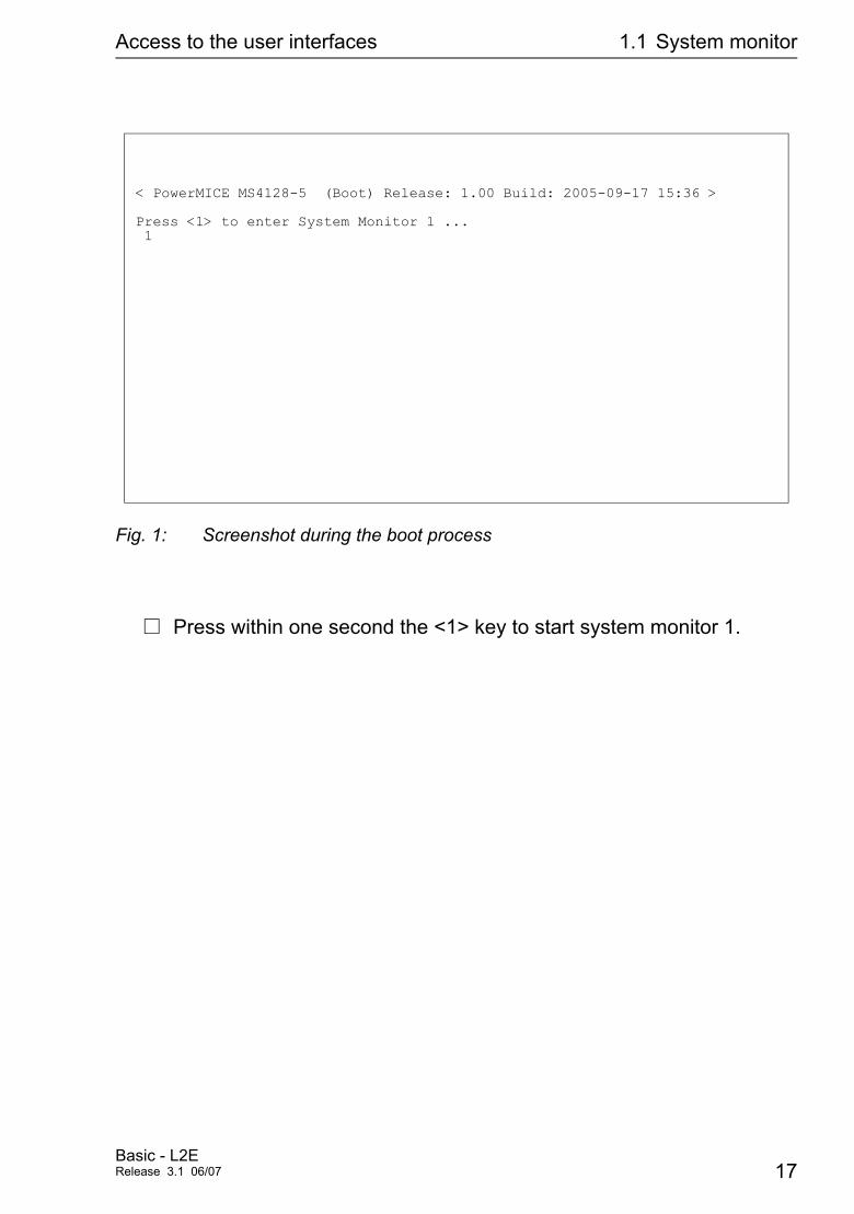
Fig. 1: Screenshot during the boot process
V Press within one second the <1> key to start system monitor 1.
< PowerMICE MS4128-5 (Boot) Release: 1.00 Build: 2005-09-17 15:36 >
Press <1> to enter System Monitor 1 ... 1
Basic - L2ERelease 3.1 06/07 17
Access to the user interfaces 1.1 System monitor
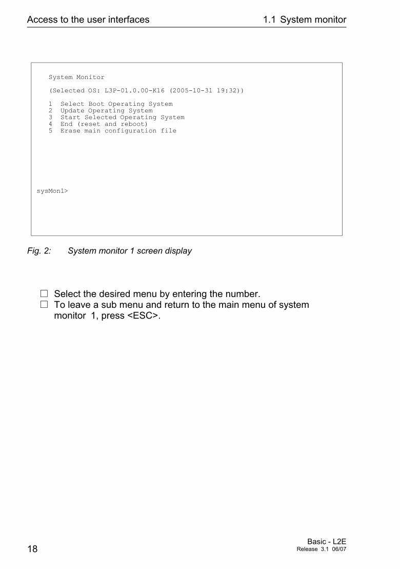
Fig. 2: System monitor 1 screen display
V Select the desired menu by entering the number.V To leave a sub menu and return to the main menu of system
monitor 1, press <ESC>.
System Monitor
(Selected OS: L3P-01.0.00-K16 (2005-10-31 19:32))
1 Select Boot Operating System 2 Update Operating System 3 Start Selected Operating System 4 End (reset and reboot) 5 Erase main configuration file
sysMon1>
18Basic - L2E
Release 3.1 06/07
Access to the user interfaces 1.2 Command Line Interface
1.2 Command Line Interface
The Command Line Interface allows you to use all device functions via a local or a remote connection. The command line interface provides IT specialists with a familiar environ-ment for configuring IT devices. The script ability of the Command Line Interfaces allows to feed several devices with identical configuration data.
For a detailed description of the Command Line Interface, see the Reference Guide „Command Line Interface“.
The Command Line Interface can be accessed via
D the V.24 (out-of-band) port orD Telnet (in-band).
Note: To facilitate making entries, the CLI offers the option of abreviating keywords. Type in the first letters of the keyword. If you now press the Tab key, the CLI will complete the keyword, i.e. add the remaining letters for you.
U Opening the Command Line InterfaceV Connect the Switch via the V.24 interface to a terminal or to a COM
port of a PC with terminal emulation according to VT 100 and press any key (see “Opening the system monitor” on page 16) or start the Command Line Interface via Telnet. A window in which you are asked to enter your username appears on the screen. A maximum of five users are permitted to access the Command Line Interface.
Basic - L2ERelease 3.1 06/07 19
Access to the user interfaces 1.2 Command Line Interface
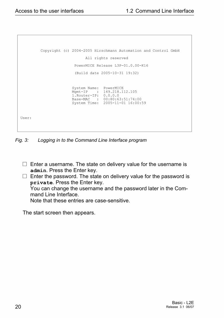
Fig. 3: Logging in to the Command Line Interface program
V Enter a username. The state on delivery value for the username is admin. Press the Enter key.
V Enter the password. The state on delivery value for the password is private. Press the Enter key. You can change the username and the password later in the Com-mand Line Interface. Note that these entries are case-sensitive.
The start screen then appears.
Copyright (c) 2004-2005 Hirschmann Automation and Control GmbH
All rights reserved
PowerMICE Release L3P-01.0.00-K16
(Build date 2005-10-31 19:32)
System Name: PowerMICE Mgmt-IP : 149.218.112.105 1.Router-IP: 0.0.0.0 Base-MAC : 00:80:63:51:74:00 System Time: 2005-11-01 16:00:59
User:
20Basic - L2E
Release 3.1 06/07
Access to the user interfaces 1.2 Command Line Interface
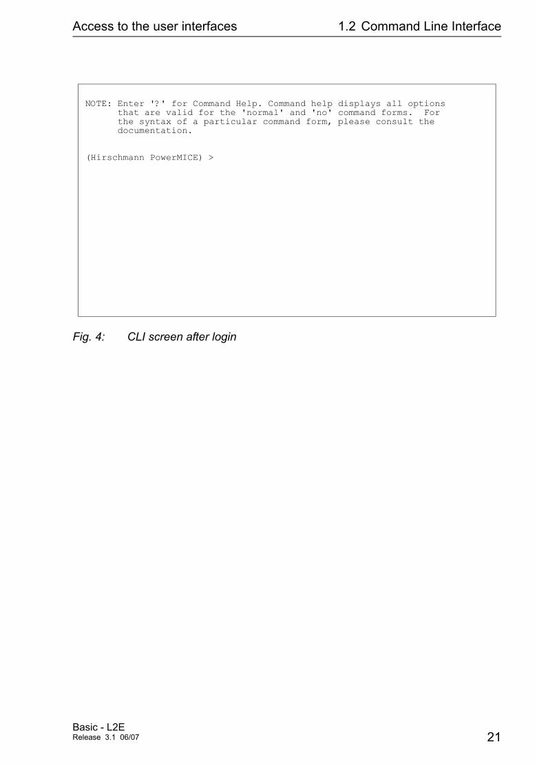
Fig. 4: CLI screen after login
NOTE: Enter '?' for Command Help. Command help displays all options that are valid for the 'normal' and 'no' command forms. For the syntax of a particular command form, please consult the documentation.
(Hirschmann PowerMICE) >
Basic - L2ERelease 3.1 06/07 21
Access to the user interfaces 1.3 Web based Interface
1.3 Web based Interface
The user-friendly Web-based interface gives you the option of operating the Switch from any location in the network via a standard browser such as the Mozilla Firefox or the Microsoft Internet Explorer. As a universal access tool, the Web browser uses an applet which commu-nicates with the Switch via the Simple Network Management Protocol (SNMP). The Web-based interface allows you to graphically configure the Switch.
U Opening the Web-based InterfaceTo open the Web-based interface, you will need a Web browser (a pro-gram that can read hypertext), for example Mozilla Firefox version 1 or higher or Microsoft Internet Explorer version 6 or higher.
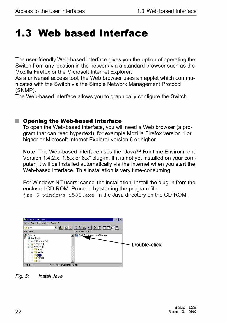
Note: The Web-based interface uses the “Java™ Runtime Environment Version 1.4.2.x, 1.5.x or 6.x” plug-in. If it is not yet installed on your com-puter, it will be installed automatically via the Internet when you start the Web-based interface. This installation is very time-consuming. For Windows NT users: cancel the installation. Install the plug-in from the enclosed CD-ROM. Proceed by starting the program file jre-6-windows-i586.exe in the Java directory on the CD-ROM.
Fig. 5: Install Java
Double-click
22Basic - L2E
Release 3.1 06/07
Access to the user interfaces 1.3 Web based Interface
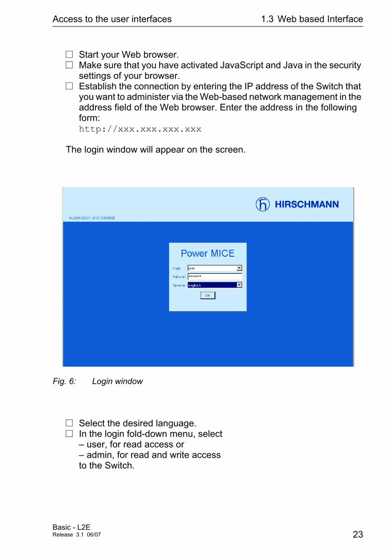
V Start your Web browser.V Make sure that you have activated JavaScript and Java in the security
settings of your browser.V Establish the connection by entering the IP address of the Switch that
you want to administer via the Web-based network management in the address field of the Web browser. Enter the address in the following form:http://xxx.xxx.xxx.xxx
The login window will appear on the screen.
Fig. 6: Login window
V Select the desired language.V In the login fold-down menu, select
– user, for read access or – admin, for read and write access to the Switch.
Basic - L2ERelease 3.1 06/07 23
Access to the user interfaces 1.3 Web based Interface
V The password “public”, with which you have read permission, appears in the password field. If you wish to access the Switch with write per-mission, then highlight the contents of the password field and overwri-te it with the password “private” (state on delivery). Changing the password protects the Switch against unauthorized access.
V Click on OK.
The Website of the Switch appears on the screen.
Note: The changes you make in the dialogs are taken over by the Switch when you click on “Write”. Click on “Load” to update the display.
Note: You can block your access to the Switch by entering an incorrect configuration. Activating the function “Cancel configuration change” in the “Load/Save” dialog enables you to return automatically to the last configuration after a set time period has elapsed. This gives you back your access to the Switch.
24Basic - L2E
Release 3.1 06/07
Entering the IP parameters
2 Entering the IP parameters
IP address(es) must be entered when the Switch is installed for the first time.
The Switch provides 6 options for entering the IP parameters during the first installation:
D Using the Command Line Interfaces (CLI). Choose this “out-of-band” method if – you preconfigure your Switch outside its operating environment, or – you have no network access (“in-band”) to the Switch (see “Entering the IP parameters via CLI” on page 32).
D Using the HiDiscovery protocol. Choose this “in-band” method if – the Switch is already installed on your network, or – if there is another Ethernet connection between your PC and the Switch available. (see “Entering the IP parameters via HiDiscovery” on page 35).
D Using the AutoConfiguration Adapter (ACA). Choose this method if you are replacing the Switch with a Switch of the same type and have already saved the configuration on an ACA (see “Loading from the AutoConfiguration Adapter” on page 53).
D Using BOOTP. Choose this “in-band” method if you want to configure the installed Switch using BOOTP. You need a BOOTP server for this. The BOOTP server as-signs the configuration data to the Switch using its MAC address (see “System configuration via BOOTP” on page 39). Because the Switch is delivered with “DHCP mode” as the entry for the configuration data re-ference, you have to reset this to the BOOTP mode for this method.
D Using DHCP. Choose this “in-band” method if you want to configure the installed Switch using DHCP. You need a DHCP server for this. The DHCP server assigns the configuration data to the Switch using its MAC address or its system name (see “System configuration via DHCP” on page 43).
Basic - L2ERelease 3.1 06/07 25
Entering the IP parameters
D Using DHCP Option 82. Choose this “in-band” method if you want to configure the installed Switch using DHCP Option 82. You need a DHCP server with Option 82 for this. The DHCP server assigns the configuration data to the Switch using its physical connection (see “System Configuration via DHCP Option 82” on page 46).
If the Switch already has an IP address and can be reached via the network, then the Web-based interface provides you with another option for configuring the IP parameters.
26Basic - L2E
Release 3.1 06/07
Entering the IP parameters 2.1 Basics IP parameter
2.1 Basics IP parameter
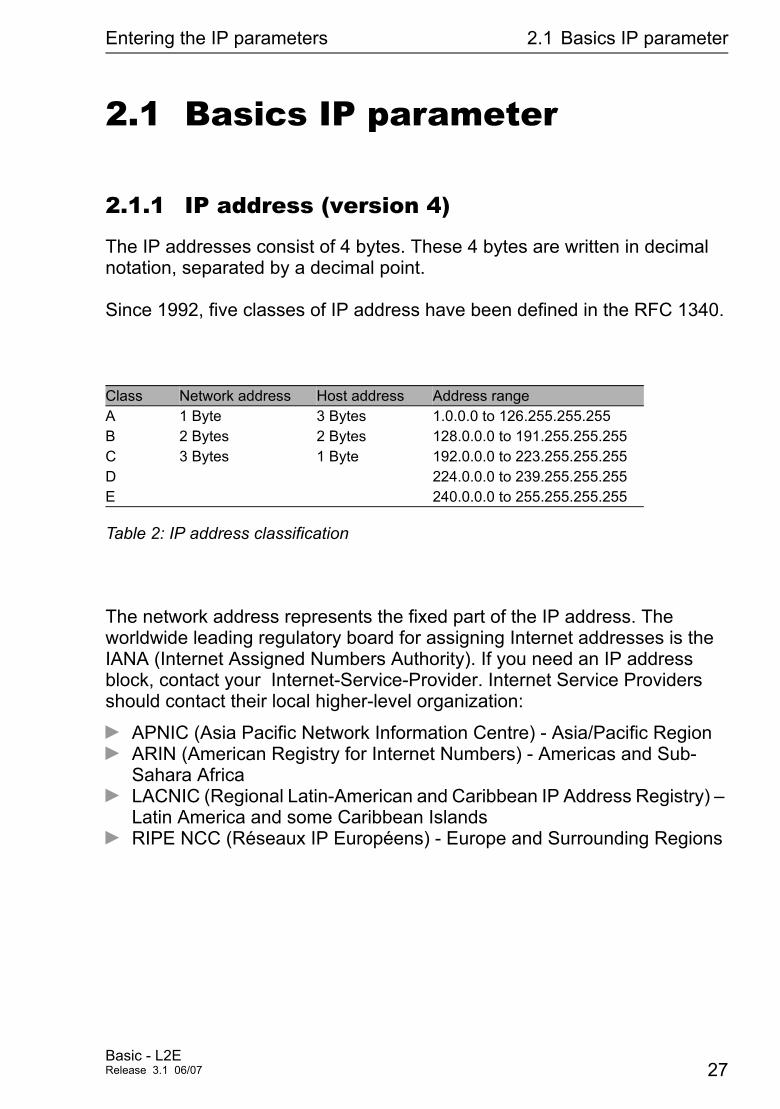
2.1.1 IP address (version 4)
The IP addresses consist of 4 bytes. These 4 bytes are written in decimal notation, separated by a decimal point.
Since 1992, five classes of IP address have been defined in the RFC 1340.
The network address represents the fixed part of the IP address. The worldwide leading regulatory board for assigning Internet addresses is the IANA (Internet Assigned Numbers Authority). If you need an IP address block, contact your Internet-Service-Provider. Internet Service Providers should contact their local higher-level organization:
D APNIC (Asia Pacific Network Information Centre) - Asia/Pacific RegionD ARIN (American Registry for Internet Numbers) - Americas and Sub-
Sahara AfricaD LACNIC (Regional Latin-American and Caribbean IP Address Registry) –
Latin America and some Caribbean IslandsD RIPE NCC (Réseaux IP Européens) - Europe and Surrounding Regions
Class Network address Host address Address rangeA 1 Byte 3 Bytes 1.0.0.0 to 126.255.255.255B 2 Bytes 2 Bytes 128.0.0.0 to 191.255.255.255C 3 Bytes 1 Byte 192.0.0.0 to 223.255.255.255D 224.0.0.0 to 239.255.255.255E 240.0.0.0 to 255.255.255.255
Table 2: IP address classification
Basic - L2ERelease 3.1 06/07 27
Entering the IP parameters 2.1 Basics IP parameter
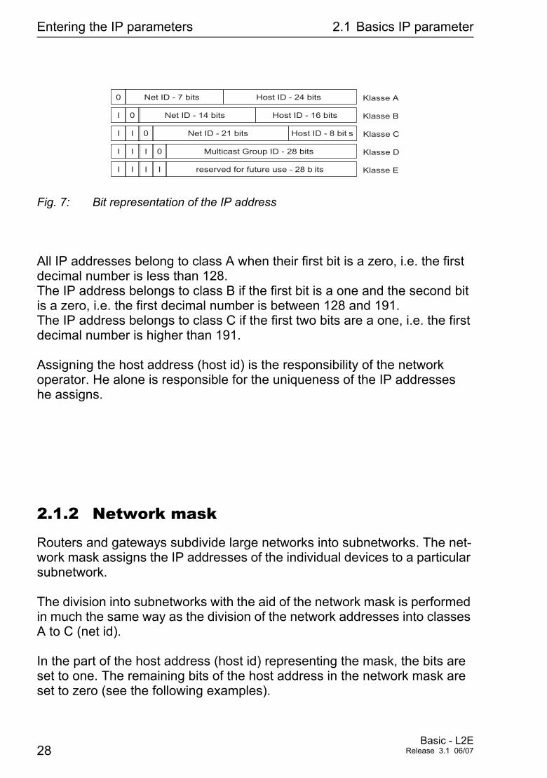
Fig. 7: Bit representation of the IP address
All IP addresses belong to class A when their first bit is a zero, i.e. the first decimal number is less than 128. The IP address belongs to class B if the first bit is a one and the second bit is a zero, i.e. the first decimal number is between 128 and 191. The IP address belongs to class C if the first two bits are a one, i.e. the first decimal number is higher than 191.
Assigning the host address (host id) is the responsibility of the network operator. He alone is responsible for the uniqueness of the IP addresses he assigns.
2.1.2 Network mask
Routers and gateways subdivide large networks into subnetworks. The net-work mask assigns the IP addresses of the individual devices to a particular subnetwork.
The division into subnetworks with the aid of the network mask is performed in much the same way as the division of the network addresses into classes A to C (net id).
In the part of the host address (host id) representing the mask, the bits are set to one. The remaining bits of the host address in the network mask are set to zero (see the following examples).
Net ID - 7 bits Host ID - 24 bits0
I
I
I
0
I
I I I
0
I I I 0
Net ID - 14 bits
Net ID - 21 bits
Multicast Group ID - 28 bits
reserved for future use - 28 b its
Klasse A
Klasse BHost ID - 16 bits
Host ID - 8 bit s Klasse C
Klasse D
Klasse E
28Basic - L2E
Release 3.1 06/07
Entering the IP parameters 2.1 Basics IP parameter
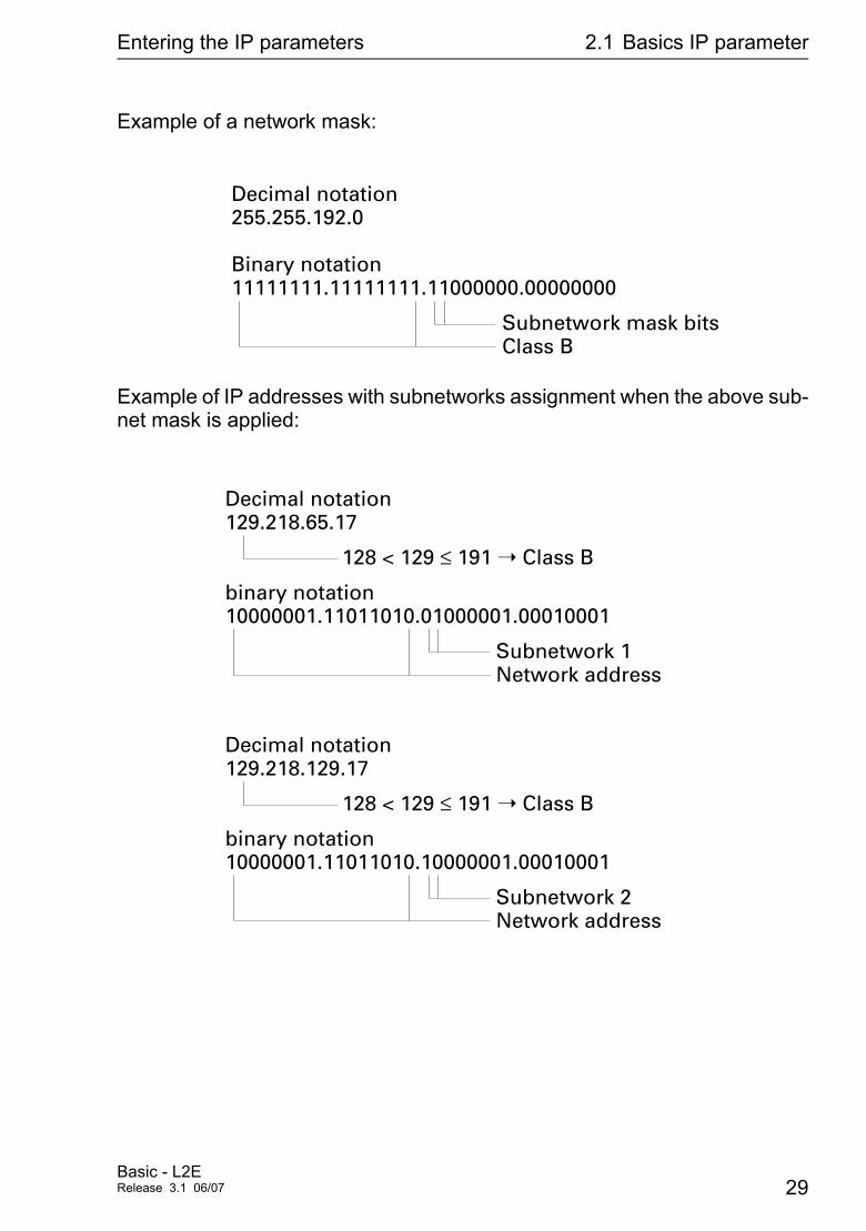
Example of a network mask:
Example of IP addresses with subnetworks assignment when the above sub-net mask is applied:
255.255.192.0Decimal notation
11111111.11111111.11000000.00000000Binary notation
Subnetwork mask bitsClass B
129.218.65.17Decimal notation
10000001.11011010.01000001.00010001binary notation
128 < 129 ≤ 191 ➝ Class B
Subnetwork 1Network address
129.218.129.17Decimal notation
10000001.11011010.10000001.00010001binary notation
128 < 129 ≤ 191 ➝ Class B
Subnetwork 2Network address
Basic - L2ERelease 3.1 06/07 29
Entering the IP parameters 2.1 Basics IP parameter
2.1.3 Example of how the network mask is used
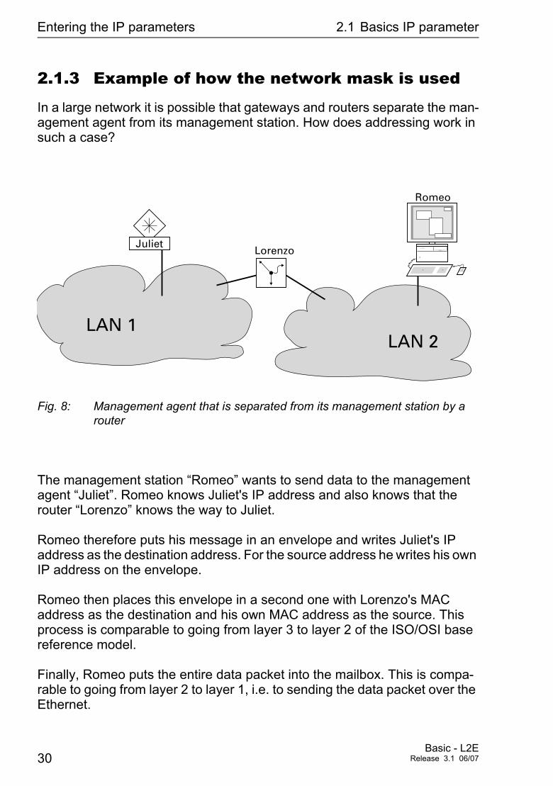
In a large network it is possible that gateways and routers separate the man-agement agent from its management station. How does addressing work in such a case?
Fig. 8: Management agent that is separated from its management station by a router
The management station “Romeo” wants to send data to the management agent “Juliet”. Romeo knows Juliet's IP address and also knows that the router “Lorenzo” knows the way to Juliet.
Romeo therefore puts his message in an envelope and writes Juliet's IP address as the destination address. For the source address he writes his own IP address on the envelope.
Romeo then places this envelope in a second one with Lorenzo's MAC address as the destination and his own MAC address as the source. This process is comparable to going from layer 3 to layer 2 of the ISO/OSI base reference model.
Finally, Romeo puts the entire data packet into the mailbox. This is compa-rable to going from layer 2 to layer 1, i.e. to sending the data packet over the Ethernet.
Romeo
LAN 1
Lorenzo
LAN 2
Juliet
30Basic - L2E
Release 3.1 06/07

Entering the IP parameters 2.1 Basics IP parameter
Lorenzo receives the letter and removes the outer envelope. From the inner envelope he recognizes that the letter is meant for Juliet. He places the inner envelope in a new outer envelope and searches his address list (the ARP table) for Juliet's MAC address. He writes her MAC address on the outer envelope as the destination address and his own MAC address as the source address. He then places the entire data packet in the mail box.
Juliet receives the letter and removes the outer envelope. She finds the inner envelope with Romeo's IP address. Opening the inner envelope and reading its contents corresponds to transferring the message to the higher protocol layers of the ISO/OSI layer model.
Juliet would now like to send a reply to Romeo. She places her reply in an envelope with Romeo's IP address as destination and her own IP address as source. But where is she to send the answer? For she did not receive Romeo's MAC address. It was lost when Lorenzo replaced the outer envelope.
In the MIB, Juliet finds Lorenzo listed under the variable hmNetGateway IPAddr as a means of communicating with Romeo. She therefore puts the envelope with the IP addresses in a further envelope with Lorenzo's MAC destination address.
The letter then travels back to Romeo via Lorenzo, the same way the first letter traveled from Romeo to Juliet.
Basic - L2ERelease 3.1 06/07 31
Entering the IP parameters 2.2 Entering the IP parameters via CLI
2.2 Entering the IP parameters via CLI
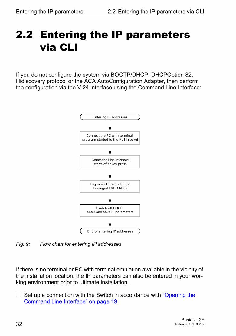
If you do not configure the system via BOOTP/DHCP, DHCPOption 82, Hidiscovery protocol or the ACA AutoConfiguration Adapter, then perform the configuration via the V.24 interface using the Command Line Interface:
Fig. 9: Flow chart for entering IP addresses
If there is no terminal or PC with terminal emulation available in the vicinity of the installation location, the IP parameters can also be entered in your wor-king environment prior to ultimate installation.
V Set up a connection with the Switch in accordance with “Opening the Command Line Interface” on page 19.
Entering IP addresses
Connect the PC with terminal program started to the RJ11 socket
Command Line Interfacestarts after key press
Log in and change to the Privileged EXEC Mode
Switch off DHCP, enter and save IP parameters
End of entering IP addresses
32Basic - L2E
Release 3.1 06/07
Entering the IP parameters 2.2 Entering the IP parameters via CLI
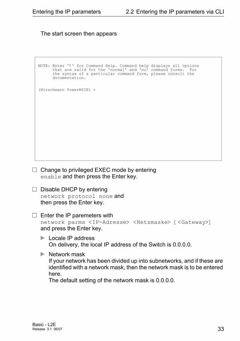
The start screen then appears
V Change to privileged EXEC mode by entering enable and then press the Enter key.
V Disable DHCP by entering network protocol none and then press the Enter key.
V Enter the IP paremeters with network parms <IP-Adresse> <Netzmaske> [<Gateway>] and press the Enter key.
D Locale IP address On delivery, the local IP address of the Switch is 0.0.0.0.
D Network mask If your network has been divided up into subnetworks, and if these are identified with a network mask, then the network mask is to be entered here. The default setting of the network mask is 0.0.0.0.
NOTE: Enter '?' for Command Help. Command help displays all options that are valid for the 'normal' and 'no' command forms. For the syntax of a particular command form, please consult the documentation.
(Hirschmann PowerMICE) >
Basic - L2ERelease 3.1 06/07 33
Entering the IP parameters 2.2 Entering the IP parameters via CLI
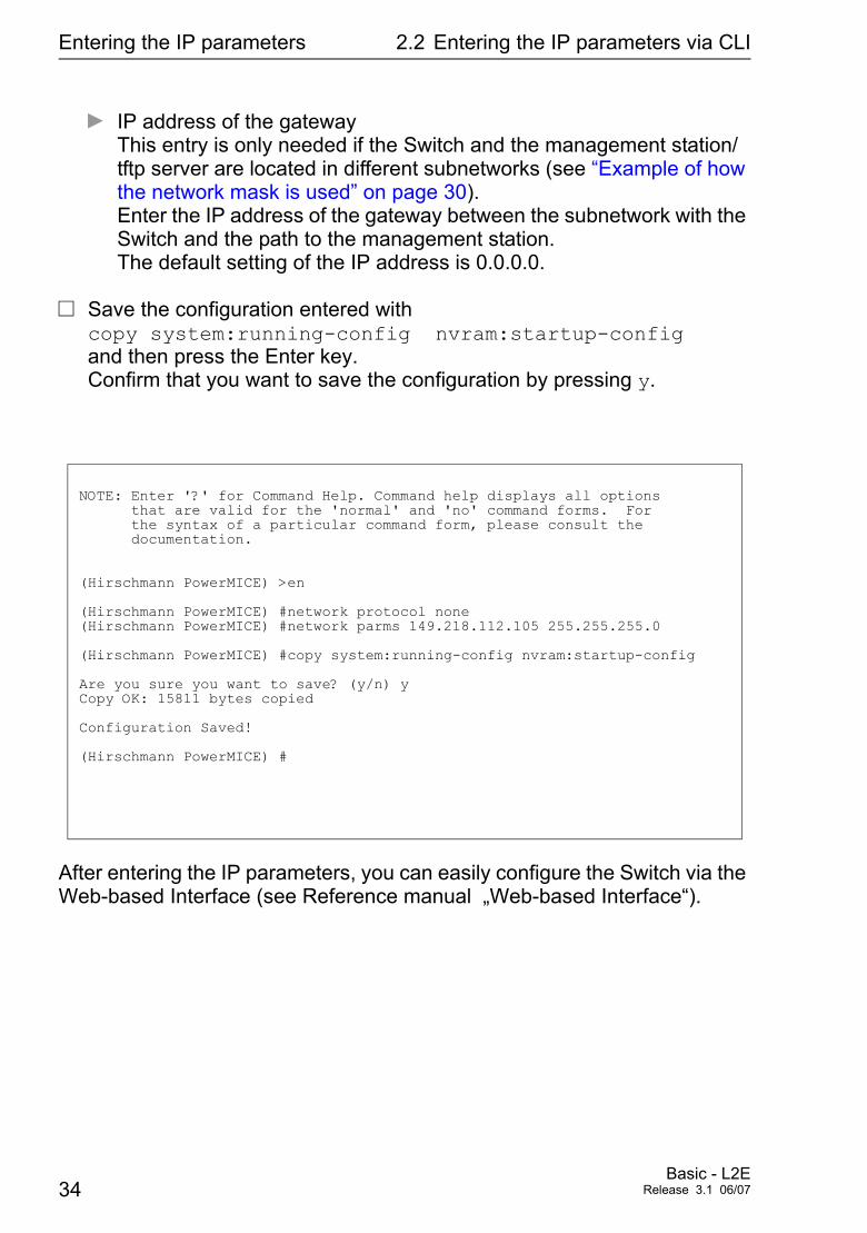
D IP address of the gateway This entry is only needed if the Switch and the management station/tftp server are located in different subnetworks (see “Example of how the network mask is used” on page 30). Enter the IP address of the gateway between the subnetwork with the Switch and the path to the management station. The default setting of the IP address is 0.0.0.0.
V Save the configuration entered with copy system:running-config nvram:startup-config and then press the Enter key. Confirm that you want to save the configuration by pressing y.
After entering the IP parameters, you can easily configure the Switch via the Web-based Interface (see Reference manual „Web-based Interface“).
NOTE: Enter '?' for Command Help. Command help displays all options that are valid for the 'normal' and 'no' command forms. For the syntax of a particular command form, please consult the documentation.
(Hirschmann PowerMICE) >en
(Hirschmann PowerMICE) #network protocol none(Hirschmann PowerMICE) #network parms 149.218.112.105 255.255.255.0
(Hirschmann PowerMICE) #copy system:running-config nvram:startup-config
Are you sure you want to save? (y/n) yCopy OK: 15811 bytes copied
Configuration Saved!
(Hirschmann PowerMICE) #
34Basic - L2E
Release 3.1 06/07
Entering the IP parameters 2.3 Entering the IP parameters via HiDiscovery
2.3 Entering the IP parameters via HiDiscovery
The HiDiscovery protocol enables you to assign IP parameters to the Switch via the Ethernet. You can easily configure additional parameters with the Web-based mana-gement (see Reference manual „Web-based Interface“).
Install the HiDiscovery software on your PC. The software is on the CD sup-plied with the Switch.
V To install it, you start the installation program on the CD.
Note: The installation of HiDiscovery involves installing the WinPcap Version 3.0 software package. If an earlier version of WinPcap is already installed on the PC, then you must first uninstall it. A newer version remains intact when you install HiDiscovery. However, this can not be guaranteed for all future versions of WinPcap. In the event that the installation of HiDiscovery has overwritten a newer version of WinPcap, then you uninstall WinPcap 3.0 and then re-install the new ver-sion.
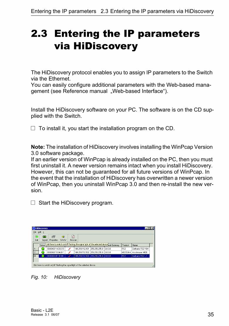
V Start the HiDiscovery program.
Fig. 10: HiDiscovery
Basic - L2ERelease 3.1 06/07 35
Entering the IP parameters 2.3 Entering the IP parameters via HiDiscovery
When HiDiscovery is started, it automatically searches the network for those devices which support the HiDiscovery protocol.HiDiscovery uses the first PC network card found. If your computer has se-veral network cards, you can select these in HiDiscovery on the toolbar.
HiDiscovery displays a line for every device which reacts to the HiDiscovery protocol.
HiDiscovery enables you to identify the devices displayed. V Select a device line. V Click on the symbol with the two green dots in the tool bar to set the LEDs
for the selected device flashing. To Switch off the flashing, click on the symbol again.
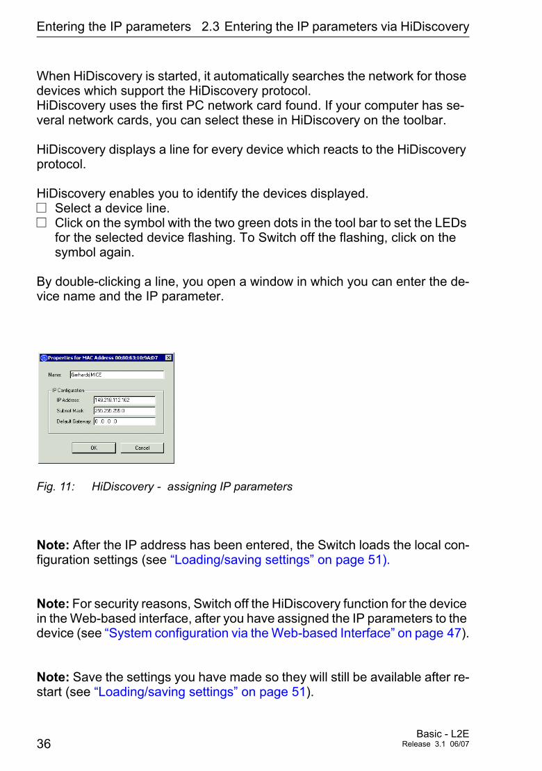
By double-clicking a line, you open a window in which you can enter the de-vice name and the IP parameter.
Fig. 11: HiDiscovery - assigning IP parameters
Note: After the IP address has been entered, the Switch loads the local con-figuration settings (see “Loading/saving settings” on page 51).
Note: For security reasons, Switch off the HiDiscovery function for the device in the Web-based interface, after you have assigned the IP parameters to the device (see “System configuration via the Web-based Interface” on page 47).
Note: Save the settings you have made so they will still be available after re-start (see “Loading/saving settings” on page 51).
36Basic - L2E
Release 3.1 06/07
Entering the IP parameters 2.4 Loading the system configuration from the
2.4 Loading the system configuration from the ACA
The ACA is a device for
D storing the configuration data of a Switch. D storing the Switch software.
In the case of a Switch failure, the ACA enables a very simple configuration data transfer by means of a substitute Switch of the same type.
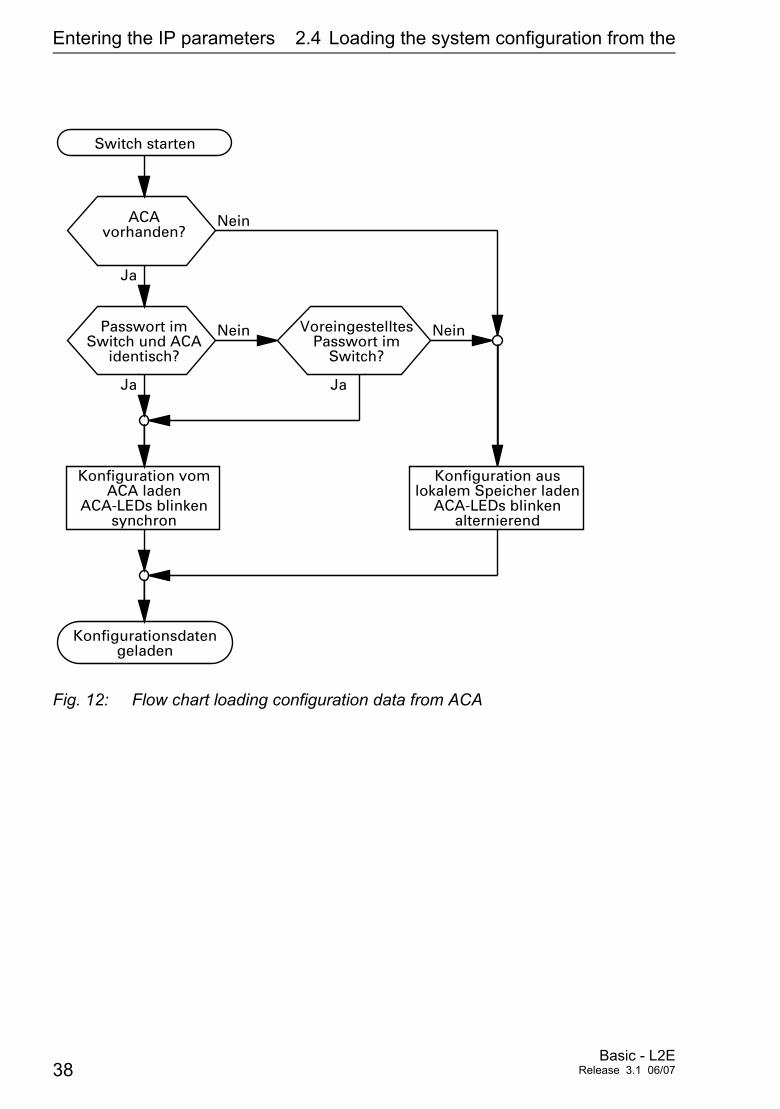
When you start the switch, it checks for an ACA. If it detects an ACA with a valid password and valid software, the Switch loads the configuration data from the ACA.
The password is valid if
D the password on the Switch matches the password on the ACA, orD the preset password is entered on the Switch.
To save the configuration data in the ACA see “Saving Locally (and on the ACA)” on page 57
Basic - L2ERelease 3.1 06/07 37
Entering the IP parameters 2.4 Loading the system configuration from the
Fig. 12: Flow chart loading configuration data from ACA
ACAvorhanden?
Ja
Konfiguration vomACA laden
ACA-LEDs blinkensynchron
Nein
Passwort imSwitch und ACA
identisch?
Ja
Nein VoreingestelltesPasswort im
Switch?
Ja
Nein
Switch starten
Konfigurationsdatengeladen
Konfiguration auslokalem Speicher laden
ACA-LEDs blinkenalternierend
38Basic - L2E
Release 3.1 06/07
Entering the IP parameters 2.5 System configuration via BOOTP
2.5 System configuration via BOOTP
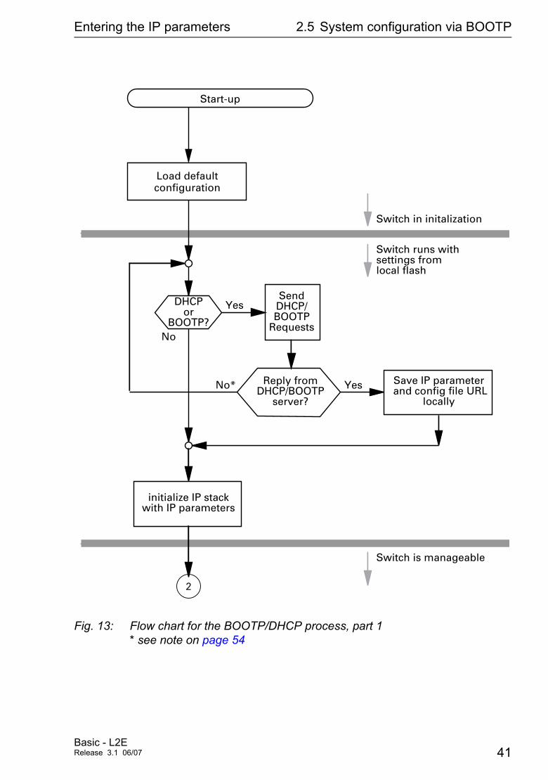
During startup operation via BOOTP (bootstrap protocol) the Switch receives its configuration data according to the “BOOTP process” flowchart (see Fig. 13).
Note: In its state on delivery, the Switch gets its configuration data from the BOOTP server.
V Activate BOOTP to receive the configuration data, see “System configu-ration via the Web-based Interface” on page 47 or see in the CLI:
V Make the following data for the Switch available to the BOOTP server:
# /etc/bootptab for BOOTP-daemon bootpd## gw -- gateways# ha -- hardware address# ht -- hardware type# ip -- IP address# sm -- subnet mask# tc -- template
.global:\:gw=0.0.0.0:\:sm=255.255.240.0:
V Change to the Priviledged EXEC mode by entering enable and then press the enter key.
V Enable BOOTP by entering configure protocol bootp an then press the enter key.
V Save the configuration entered with copy system:running-config nvram:startup-config and then press the Enter key. Confirm that you want to save the configuration by pressing y.
Basic - L2ERelease 3.1 06/07 39
Entering the IP parameters 2.5 System configuration via BOOTP
switch_01:ht=ether net:ha=008063086501:ip=149.218.17.83:tc=.global:switch_02:ht=ether net:ha=008063086502:ip=149.218.17.84:tc=.global:..
Lines that start with a '#' character are comment lines.
The lines under “.global:” make the configuration of several devices easier. With the template (tc) you allocate the global configuration data (tc=.global:). The direct allocation of hardware address and IP address occurs in the de-vice lines (switch-0...).
V Enter one line for each device.V After ha= enter the hardware address of the device.V After ip= enter the IP address of the device.
Refer to “Setting up DHCP/BOOTP Server” on page 170) for a BOOTP/DHCP server configuration example.
40Basic - L2E
Release 3.1 06/07
Entering the IP parameters 2.5 System configuration via BOOTP
Fig. 13: Flow chart for the BOOTP/DHCP process, part 1 * see note on page 54
2
DHCPor
BOOTP?
SendDHCP/BOOTP
Requests
Reply fromDHCP/BOOTP
server?
Yes
Yes Save IP parameter and config file URL
locally
initialize IP stackwith IP parameters
No
No*
Start-up
Switch in initalization
Switch runs with settings from local flash
Switch is manageable
Load defaultconfiguration
Basic - L2ERelease 3.1 06/07 41
Entering the IP parameters 2.5 System configuration via BOOTP
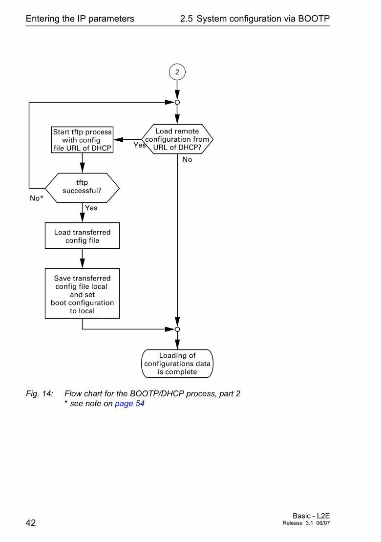
Fig. 14: Flow chart for the BOOTP/DHCP process, part 2 * see note on page 54
Load transferredconfig file
No
Yes
Load remoteconfiguration from
URL of DHCP?
No*Yes
Start tftp processwith config
file URL of DHCP
tftpsuccessful?
Save transferredconfig file local
and setboot configuration
to local
2
Loading ofconfigurations data
is complete
42Basic - L2E
Release 3.1 06/07
Entering the IP parameters 2.6 System configuration via DHCP
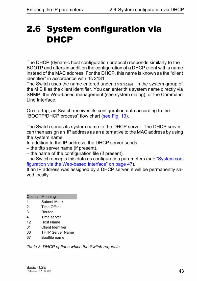
2.6 System configuration via DHCP
The DHCP (dynamic host configuration protocol) responds similarly to the BOOTP and offers in addition the configuration of a DHCP client with a name instead of the MAC address. For the DHCP, this name is known as the “client identifier” in accordance with rfc 2131. The Switch uses the name entered under sysName in the system group of the MIB II as the client identifier. You can enter this system name directly via SNMP, the Web-based management (see system dialog), or the Command Line Interface.
On startup, an Switch receives its configuration data according to the “BOOTP/DHCP process” flow chart (see Fig. 13).
The Switch sends its system name to the DHCP server. The DHCP server can then assign an IP address as an alternative to the MAC address by using the system name. In addition to the IP address, the DHCP server sends – the tftp server name (if present), – the name of the configuration file (if present). The Switch accepts this data as configuration parameters (see “System con-figuration via the Web-based Interface” on page 47). If an IP address was assigned by a DHCP server, it will be permanently sa-ved locally.
Option Meaning1 Subnet Mask2 Time Offset3 Router4 Time server12 Host Name61 Client Identifier66 TFTP Server Name67 Bootfile name
Table 3: DHCP options which the Switch requests
Basic - L2ERelease 3.1 06/07 43
Entering the IP parameters 2.6 System configuration via DHCP
The special feature of DHCP in contrast to BOOTP is that the server can only provide the configuration parameters for a certain period of time (“lease”). When this time period (“lease duration”) expires, the DHCP client must at-tempt to renew the lease or negotiate a new one. A response similar to BOOTP can be set on the server (i.e. the same IP address is always assi-gned to a particular client using the MAC address), but this requires the ex-plicit configuration of a DHCP server in the network. If this configuration was not performed, a random IP address – whichever one happens to be availa-ble – is assigned.
On delivery DHCP is enabled.
As long as DHCP is activated, the Switch attempts to obtain an IP address. If it cannot find a DHCP server after restarting, it will not have an IP address. To activate/deactivate DHCP, see “System configuration via the Web-based Interface” on page 47.
Note: When using HiVision network management, ensure that DHCP always assigns the original IP address to each Switch.
Refer to “Setting up DHCP/BOOTP Server” on page 170) for a BOOTP/DHCP server configuration example.
Example of a DHCP configuration file:
# /etc/dhcpd.conf for DHCP Daemon#subnet 149.218.112.0 netmask 255.255.240.0 {
option subnet-mask 255.255.240.0;option routers 149.218.112.96;
}# # Host berta requests IP configuration # with her MAC address# host berta {
hardware ethernet 00:80:63:08:65:42;fixed-address 149.218.112,82;}
44Basic - L2E
Release 3.1 06/07
Entering the IP parameters 2.6 System configuration via DHCP
# # Host hugo requests IP configuration # with his client identifier.# host hugo {# option dhcp-client-identifier "hugo";
option dhcp-client-identifier 00:68:75:67:6f;fixed-address 149.218.112.83;server-name "149.218.112.11";filename "/agent/config.dat";}
Lines that start with a '#' character are comment lines. The lines preceding the individually listed devices refer to settings that apply to all the following devices. The fixed-address line assigns a permanent IP address to the device. For further information, please refer to the DHCP server manual.
Basic - L2ERelease 3.1 06/07 45
Entering the IP parameters 2.7 System Configuration via DHCP Option 82
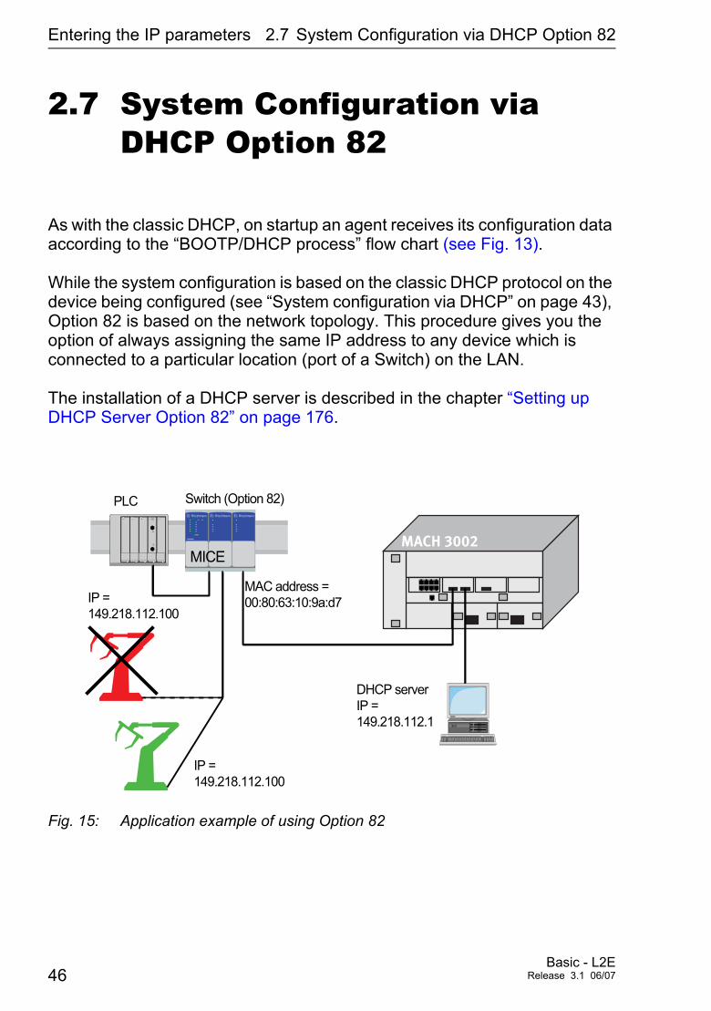
2.7 System Configuration via DHCP Option 82
As with the classic DHCP, on startup an agent receives its configuration data according to the “BOOTP/DHCP process” flow chart (see Fig. 13).
While the system configuration is based on the classic DHCP protocol on the device being configured (see “System configuration via DHCP” on page 43), Option 82 is based on the network topology. This procedure gives you the option of always assigning the same IP address to any device which is connected to a particular location (port of a Switch) on the LAN.
The installation of a DHCP server is described in the chapter “Setting up DHCP Server Option 82” on page 176.
Fig. 15: Application example of using Option 82
PLC Switch (Option 82)
IP =149.218.112.100
IP =149.218.112.100
MAC address =00:80:63:10:9a:d7
DHCP serverIP =149.218.112.1
�� �� ��
MACH 3002MICE
46Basic - L2E
Release 3.1 06/07
Entering the IP parameters 2.8 System configuration via the Web-based
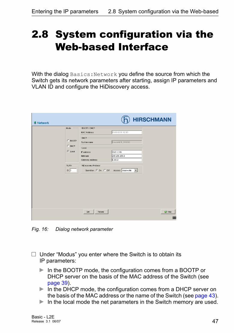
2.8 System configuration via the Web-based Interface
With the dialog Basics:Network you define the source from which the Switch gets its network parameters after starting, assign IP parameters and VLAN ID and configure the HiDiscovery access.
Fig. 16: Dialog network parameter
V Under “Modus” you enter where the Switch is to obtain its IP parameters:
D In the BOOTP mode, the configuration comes from a BOOTP or DHCP server on the basis of the MAC address of the Switch (see page 39).
D In the DHCP mode, the configuration comes from a DHCP server on the basis of the MAC address or the name of the Switch (see page 43).
D In the local mode the net parameters in the Switch memory are used.
Basic - L2ERelease 3.1 06/07 47
Entering the IP parameters 2.8 System configuration via the Web-based
V Enter the parameters according to the selected mode on the right.
V You enter the system name applicable to the DHCP protocol in the Sy stem dialog of the Web-based Interfaces, in the “Name” line.
V In the “Local” frame assign – an IP address, – a Netmask and – a Gateway Address to the Switch.
V With the “VLAN ID” frame you can assign a VLAN to the Switch. If you enter the illegal VLAN ID “0” here, the agent can be accessed by all VLANs.
V The HiDiscovery protocol (see “Entering the IP parameters via HiDiscov-ery” on page 35) allows you to assign an IP address to the Switch on the basis of its MAC address. Activate the HiDiscovery protocol if you want to assign an IP address to the Switch from your PC with the HiDiscovery software delivered (setting on delivery: active).
Note: Save the settings you have made to ensure they are still available after restart (see “Loading/saving settings” on page 51).
48Basic - L2E
Release 3.1 06/07
Entering the IP parameters 2.9 Faulty Device Replacement
2.9 Faulty Device Replacement
There are two plug-and-play solutions available for replacing a faulty Switch with a Switch of the same type (Faulty Device Replacement):
D First, you can configure the new switch using an AutoConfiguration Adapter (see “Loading the system configuration from the ACA” on page 37) or
D Second, you can configure the new switch using DHCP Option 82 (see “System Configuration via DHCP Option 82” on page 46).
In both cases, the same configuration data which the faulty Switch had are transferred to the new Switch during booting.
Basic - L2ERelease 3.1 06/07 49

Entering the IP parameters 2.9 Faulty Device Replacement
50Basic - L2E
Release 3.1 06/07

Loading/saving settings
3 Loading/saving settings
The Switch saves settings such as the IB parameters and the port configuration in the temporary memory. These settings are lost when you switch off or reboot the device.The Switch enables you to
D save settings from the temporary memory in a permanent memory
D load settings from a permanent memory into the temporary memory.
Basic - L2ERelease 3.1 06/07 51
Loading/saving settings 3.1 Loading settings
3.1 Loading settings
During restart, the Switch automatically loads its configuration data from the local non-volatile memory, provided that you have not activated BOOTP/DHCP and that no ACA is connected to the Switch.
During operation, the Switch enables you to load settings from the following sources:
D the local non-volatile memory,
D the AutoConfiguration Adapter. If an ACA is connected to the Switch, the Switch always loads its configuration from the ACA.
D a file in the connected network (= state on delivery)
D a binary file or an editable and readable script on the PC and
D the state on delivery.
Note: When loading a configuration, do not access the Switch until it has loaded the configuration file and has made the new configuration settings. Depending on the complexity of the configuration settings, this procedure can last between 10-200 seconds.
52Basic - L2E
Release 3.1 06/07
Loading/saving settings 3.1 Loading settings
3.1.1 Loading from the local non-volatile memory
When loading the configuration data locally, the Switch loads the configuration data from the local permanent memory if no ACA is connected to the Switch.
3.1.2 Loading from the AutoConfiguration Adapter
If an ACA is connected to the Switch, the Switch always loads its configura-tion from the ACA. For information on how to save a configuration file onto an ACA, refer to “Sa-ving Locally (and on the ACA)” on page 57.
V Select the Basics:Load/Save dialog. V Click in the “Load”-frame “Local”.V Click “Load configuration”.
V Enter the command enable to change to the Privileged EXEC mode.
V Enter the command copy nvram:startup-config system:running-config to load the configuration data from the local non-volatile memory.
Basic - L2ERelease 3.1 06/07 53
Loading/saving settings 3.1 Loading settings
3.1.3 Loading from a file
The Switch allows you to load the configuration data from a file in the connected network if there is no AutoConfiguration Adapter connected to the Switch.
V Select the Basics:Load/Save dialog.V Click in the Load"-frame “fromURL”, if you want the Switch to load
the configuration data from a file and to retain the locally saved con-figuration. Click in the Load"-frame “from URL & save local”, if you want the Switch to load the configuration data from a file and to save this con-figuration locally. “via PC (script/binary)” when you want the Switch to load the con-figuration data from a file from the PC and retain the locally saved configuration.
V In the “URL” edit box, type the field path under which the Switch finds the configuration file if you want to load from URL.
V Click “Load configuration”.
The URL identifies the path to the tftp server from which the Switch loads the configuration file. The URL is in the form tftp://IP address of the tftp server/path name/file name (e.g. tftp://149.218.112.5/switch/config.dat).
Example of loading a file from the TFTPServerV To enable yourself to download a file from the tftp server, save the
configuration file into the corresponding path of the tftp server with the file name, e.g.. switch/switch_01.cfg (see “Saving into a file on URL” on page 58).
V Enter the path to the tftp server into the line “URL”, e.g. tftp://149.218.112.214/switch/switch_01.cfg .
Note: The status of the load, started by DHCP/BOOTP (see “System configuration via BOOTP” on page 39), is displayed in the selected op-tion “from URL & save local” in the “Load” frame. If you get an error mes-sage while saving the configuration, one reason may be that loading is not completed. DHCP/BOOTP does not finish loading until a valid confi-guration is loaded. If DHCP/BOOTP does not find any valid configuration you can stop the active loading by loading the local configuration in the “Load” frame.
54Basic - L2E
Release 3.1 06/07
Loading/saving settings 3.1 Loading settings
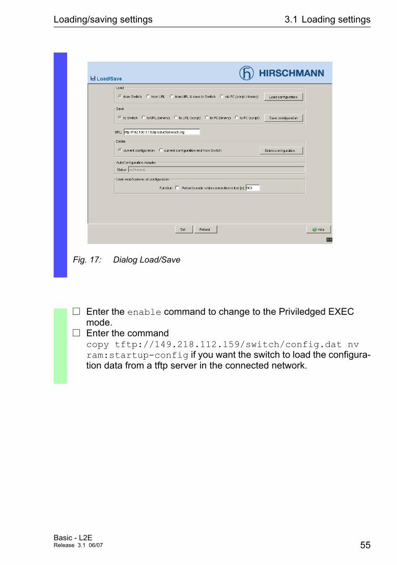
Fig. 17: Dialog Load/Save
V Enter the enable command to change to the Priviledged EXEC mode.
V Enter the command copy tftp://149.218.112.159/switch/config.dat nv ram:startup-config if you want the switch to load the configura-tion data from a tftp server in the connected network.
Basic - L2ERelease 3.1 06/07 55
Loading/saving settings 3.1 Loading settings
3.1.4 Resetting the configuration to the state on delivery
The Switch gives you the option to,
D reset the current configuration to the state on delivery. The locally saved configuration remains.
D reset the Switch to the state on delivery. After restarting, the IP address is also in the original delivery state.
Setting in the System Monitor:V Select 5 “Erase main configuration file”
This menu offers you the possibility to set the Switch to its state of delivery. Configurations being different from the state of delivery are saved in the flash memory in the switch.cfg file by the Switch.
V Press the enter key to erase the switch.cfg file.
V Select the Basics:Load/Save dialog.V Make your choice in the “Delete”-frame.V Click“Delete configuration”.
56Basic - L2E
Release 3.1 06/07
Loading/saving settings 3.2 Saving settings
3.2 Saving settings
The Switch enables you to save the settings you have madeD locallyD locally and on the ACA, orD into a file.
3.2.1 Saving Locally (and on the ACA)
The Switch allows you to save the current configuration data in the local permanent memory and the ACA.
V Select the Basics:Load/Save dialog.V Click in the “Save”-frame “to Switch”.V Click “Save configuration”.
As a result, the Switch saves the current configuration data into the local nonvolatile memory and, provided that an ACA is connected, also into the ACA.
V Enter the enable command to change to the Priviledged EXEC mode.
V Enter the command copy system:running-config nvram:startup-config to save the current configuration data into both the local non-volatile memory and into the ACA if an ACA is connected.
Basic - L2ERelease 3.1 06/07 57
Loading/saving settings 3.2 Saving settings
3.2.2 Saving into a file on URL
The Switch allows you to save the current configuration data in a file in the connected network.
V Select the Basics:Load/Save dialog.V In the “Save” frame, click on
“in URL (binary)” to receive a binary file, or “in URL (script)” to receive an editable and readable script.
V Type in the “URL” edit field the path under which you want the Switch to save the configuration file.
V Click “Save configuration”.
The URL marks the path to the tftp server on which the Switch saves the configuration file. The URL is written as follows: tftp://IP address of the tftp server/path name/file name, (e.g. tftp://149.218.112.5/switch/config.dat).
Note: The configuration file contains all configuration data, including the password. Thus, note the access rights on the tftp server..
V Enter the enable command to change to the Priviledged EXEC mode.
V Enter the command copy nvram:startup-config tftp://149.218.112.159/switch/config.dat if you want the Switch to save the current configuration data into a binary file on a tftp server in the connected network.
V Enter the command copy nvram:startup-config tftp://149.218.112.159/switch/config.txt if you want the Switch to save the current configuration data into a script file on a tftp server in the connected network.
58Basic - L2E
Release 3.1 06/07
Loading/saving settings 3.2 Saving settings
3.2.3 Saving into a binary file on the PC
The Switch allows you to save the current configuration data in a binary file on your PC.
3.2.4 Saving as script on the PC
The Switch allows you to save the current configuration data in a editable and readable file on your PC.
V Select the Basics:Load/Save dialog.V Click in the “Save”-frame „to PC (binary)“.V Enter in the "Save"-window the file name under which you want the
Switch to save the configuration file.V Click “Save configuration”.
V Select the Basics:Load/Save dialog.V Click in the “Save”-frame „to PC (script)“.V Enter in the "Save"-window the file name under which you want the
Switch to save the configuration file.V Click “Save configuration”.
Basic - L2ERelease 3.1 06/07 59

Loading/saving settings 3.2 Saving settings
60Basic - L2E
Release 3.1 06/07
Loading Software Updates
4 Loading Software Updates
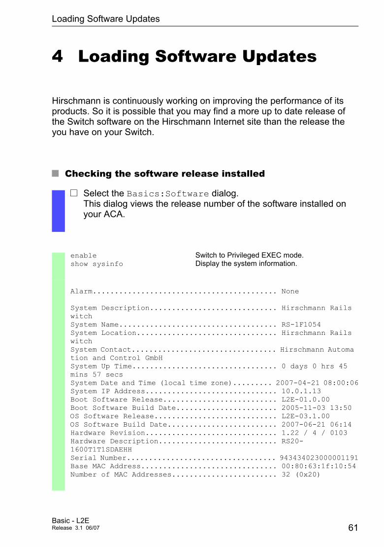
Hirschmann is continuously working on improving the performance of its products. So it is possible that you may find a more up to date release of the Switch software on the Hirschmann Internet site than the release the you have on your Switch.
U Checking the software release installed
V Select the Basics:Software dialog. This dialog views the release number of the software installed on your ACA.
enable show sysinfo
Switch to Privileged EXEC mode. Display the system information.
Alarm.......................................... None
System Description............................. Hirschmann Rails witchSystem Name.................................... RS-1F1054System Location................................ Hirschmann Rails witchSystem Contact................................. Hirschmann Automa tion and Control GmbHSystem Up Time................................. 0 days 0 hrs 45 mins 57 secsSystem Date and Time (local time zone)......... 2007-04-21 08:00:06System IP Address.............................. 10.0.1.13Boot Software Release.......................... L2E-01.0.00Boot Software Build Date....................... 2005-11-03 13:50OS Software Release............................ L2E-03.1.00OS Software Build Date......................... 2007-06-21 06:14Hardware Revision.............................. 1.22 / 4 / 0103Hardware Description........................... RS20-1600T1T1SDAEHHSerial Number.................................. 943434023000001191Base MAC Address............................... 00:80:63:1f:10:54Number of MAC Addresses........................ 32 (0x20)
Basic - L2ERelease 3.1 06/07 61

Loading Software Updates
U Loading the softwareThe Switch gives you three options for loading the software:D From the ACA 21-USB (out-of-band)D Via tftp from a tftp server (in-band)D Via a file selector window from your PC
Note: The existing configuration of the Switch is still there after the new software is installed.
62Basic - L2E
Release 3.1 06/07
Loading Software Updates 4.1 Loading the Software from the ACA
4.1 Loading the Software from the ACA
Like an usual USB stick, you can also connect the ACA 21-USB to an USB port of your PC and copy the Switch software to the main directory of the ACA 21-USB.
V Connect the ACA 21-USB, to which you have copied the Switch software, to the USB port of the Switch.
V Open the system monitor. (see “Opening the system monitor” on page 16).
V Select 2, and press the ENTER key to copy the software from the ACA 21-USB into the local memory of the Switch. On concluding the update, the System Monitor prompts you to press any key to continue..
V Select 3 to start the new software on the Switch.
In addition, the system monitor features further options in connection with your Switch software:
D Swapping the software images availableD Starting the software,D Performing a cold start.
4.1.1 Swapping the software available
In this menu item of the system monitor you select one of two possible software releases that you want to load.The following window appears on the screen:
Basic - L2ERelease 3.1 06/07 63
Loading Software Updates 4.1 Loading the Software from the ACA
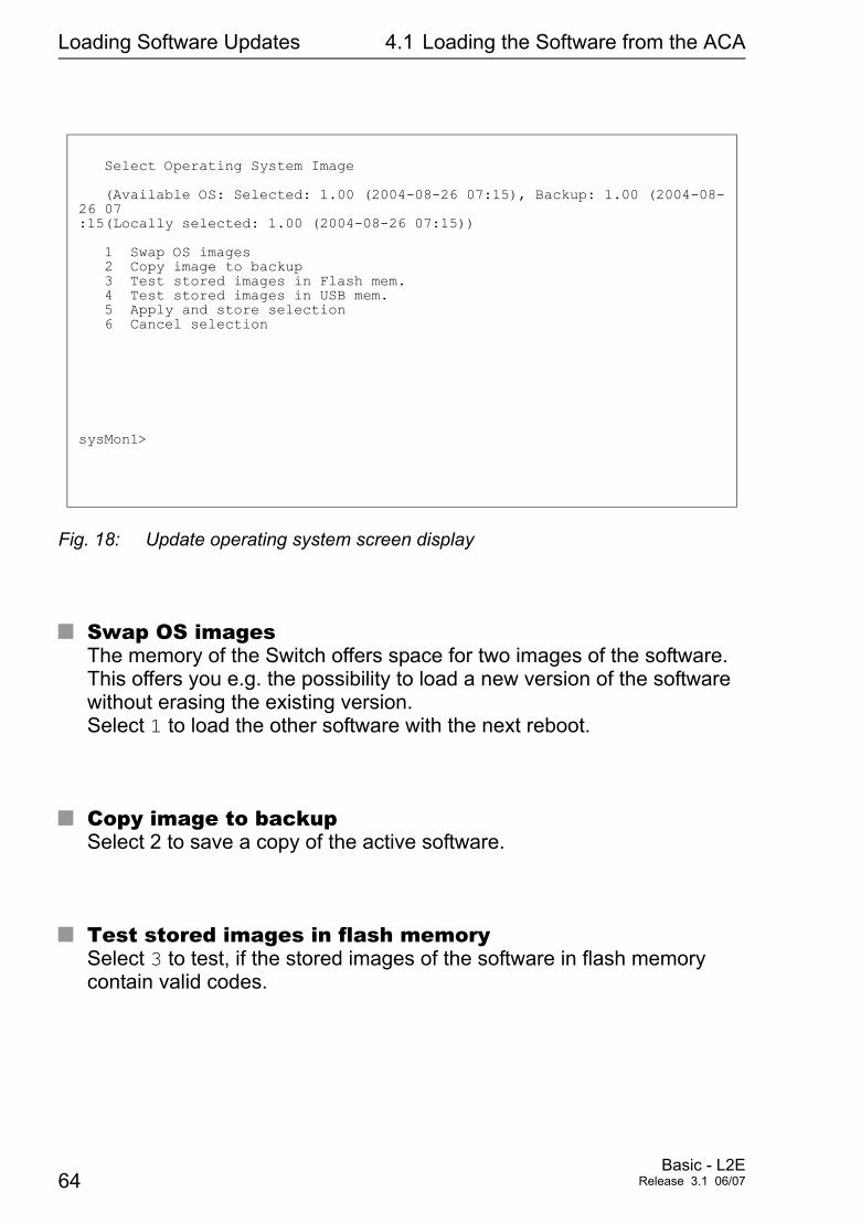
Fig. 18: Update operating system screen display
U Swap OS imagesThe memory of the Switch offers space for two images of the software. This offers you e.g. the possibility to load a new version of the software without erasing the existing version. Select 1 to load the other software with the next reboot.
U Copy image to backupSelect 2 to save a copy of the active software.
U Test stored images in flash memorySelect 3 to test, if the stored images of the software in flash memory contain valid codes.
Select Operating System Image
(Available OS: Selected: 1.00 (2004-08-26 07:15), Backup: 1.00 (2004-08-26 07:15(Locally selected: 1.00 (2004-08-26 07:15))
1 Swap OS images 2 Copy image to backup 3 Test stored images in Flash mem. 4 Test stored images in USB mem. 5 Apply and store selection 6 Cancel selection
sysMon1>
64Basic - L2E
Release 3.1 06/07
Loading Software Updates 4.1 Loading the Software from the ACA
U Test stored images in USB memorySelect 4 to test, if the stored images of the software in ACA 21-USB con-tain valid codes.
U Apply and store selectionSelect 5 to apply and store the selection of the software.
U Cancel selectionSelect Sie 6 to cancel selection and leave this dialogue without changes.
4.1.2 Starting the software
This menu of the System monitor offers you the possibility to start the selec-ted software.
4.1.3 Performing a cold start
This menu of the system monitor offers you the possibility to reset the hard-ware of the Switch and to reboot.
Basic - L2ERelease 3.1 06/07 65
Loading Software Updates 4.2 Loading the Software from the tftp Server
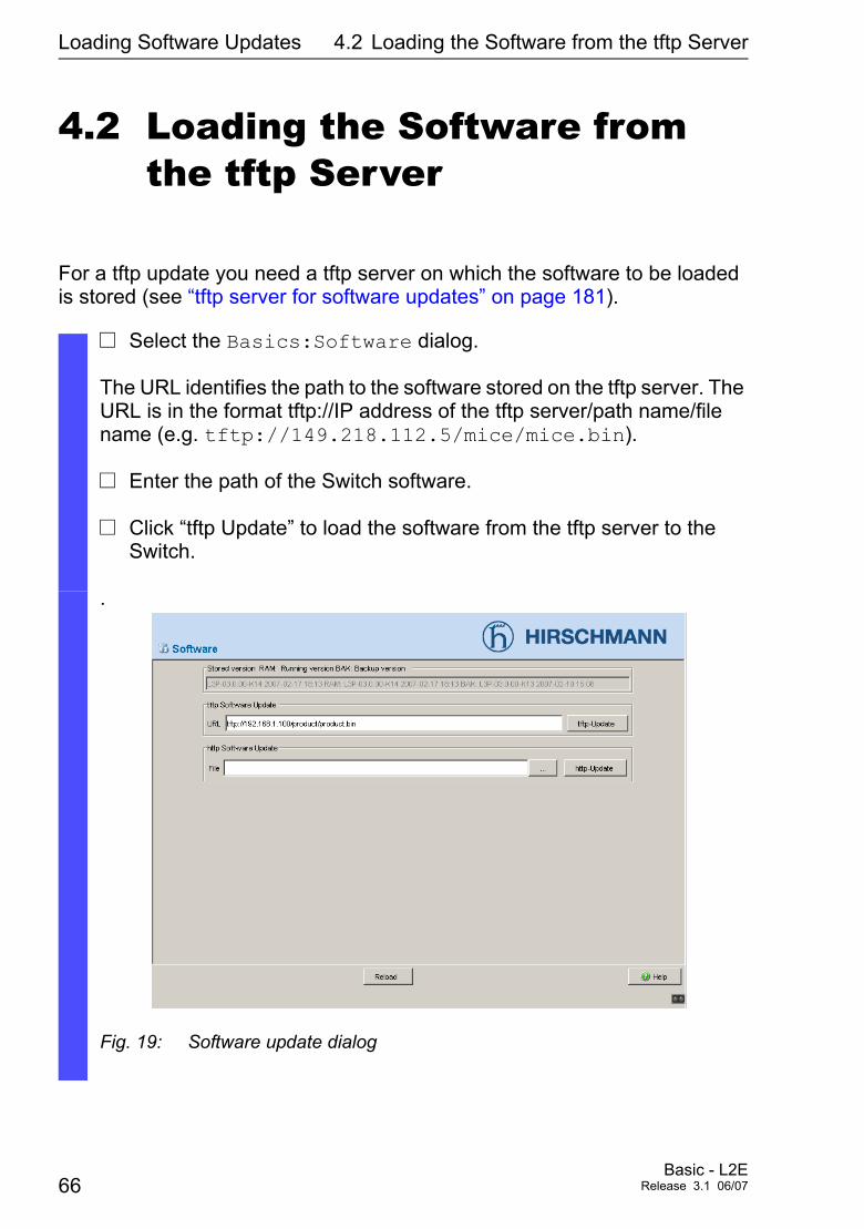
4.2 Loading the Software from the tftp Server
For a tftp update you need a tftp server on which the software to be loaded is stored (see “tftp server for software updates” on page 181).
V Select the Basics:Software dialog.
The URL identifies the path to the software stored on the tftp server. The URL is in the format tftp://IP address of the tftp server/path name/file name (e.g. tftp://149.218.112.5/mice/mice.bin).
V Enter the path of the Switch software.
V Click “tftp Update” to load the software from the tftp server to the Switch.
.
Fig. 19: Software update dialog
66Basic - L2E
Release 3.1 06/07
Loading Software Updates 4.2 Loading the Software from the tftp Server
V After the loading procedure has been completed successfully, activa-te the new software as follows: Select the Basics:Restart dialog und and perform a cold start.
V After booting the switch, click “Reload” in your browser to re-enable your access to the Switch.
enable copy tftp://10.0.1.159/rsL2E.bin system:image
Switch to the Privileged EXEC mode. Transfer the software file „rsL2E.bin” from the tftp server with the IP address 10.0.1.159 to the Switch.
Basic - L2ERelease 3.1 06/07 67
Loading Software Updates 4.3 Loading Software via file selector
4.3 Loading Software via file selector
For an update via a file selector window you need the Switch software on a drive which you can reach via your PC.
V Select the Basics:Software dialog.
V In the file selection frame, click on “...”.
V In the file selection window, select the Switch software (switch.bin) and click on “Open”.
V Click “Update”, to transfer the software to the Switch.
The end of the update is indicated by one of the following messages:D Update completed successfully.D Update failed. Reason: incorrect file.D Update failed. Reason: file damaged.D Update failed. Reason: flash error.
V After the software procedure has been completed successfully, go to Basics:Restart, and perform a cold start (“Restart Switch”).
V Click “Reload” in your browser to re-enable Switch access after boo-ting.
68Basic - L2E
Release 3.1 06/07
Configuring ports
5 Configuring ports
The port configuration consists of:
D Switching the port on and off,D Selecting the operation mode,D Displaying connection error messages,D Configuring Power over Ethernet.
U Switching the port on and offIn the state on delivery, all ports are switched on. To enhance access security, switch off the ports which you do not wish to connect..
U Selecting the Operation ModeIn the state on delivery, all ports are switched to the “Automatic Configu-ration” mode.
V Select the Basics:Port Configuration dialog..V Select in the “Port on” column the ports which are connected to a
device.
V Select the Basics:Port Configuration Table dialog.V If the device connected to this port requires a fixed setting
– select the operation mode (transmission rate, duplex operation) in the “Manual Configuration” colimn, and – deactivate the port in the “Autonegotiation” column.
Note: The active automatic configuration has priority over the manual configuration.
Basic - L2ERelease 3.1 06/07 69
Configuring ports
U Displaying connection error messagesIn the state on delivery the Switch displays a connection error via the signal contact and the LED display. The Switch allows you to disable the displaying of connection error messages, for instance to prevent a device that has been turned off from being interpreted as an interrupted line.
U Configuring Power over ETHERNETIf the Switch is equipped with PoE media modules, it will then offer you the option of supplying current to devices such as IP phones via the twisted-pair cable. PoE media modules support Power over ETHERNET according to IEEE 802.3af. The Power over Ethernet function is activated global and on all ports by default.
Systempower for MS20/MS30 and Power MICE The Switch provides the rated system performance for the sum of all PoE ports plus a surplus. Because the PoE media module gets its operating voltage externally, the Switch does not know the possible system power. The Switch therefore assumes a “nominal system power” of 60 Watt per PoE media module for now.
System power for MACH 4000 The Switch provides the rated system performance for the sum of all PoE ports plus a surplus. Should the connected devices require more power than is provided by the system, the Switch will then disable the ports. Initially, the Switch disables the ports with the lowest PoE priority. If several ports have the same priority, the switch will first disable the ports with the higher port number.
V Select the Basics:Port Configuration dialog.V In the “Signal Contact mask” column, select the ports whose connec-
tions you want to have monitored.
70Basic - L2E
Release 3.1 06/07

Configuring ports
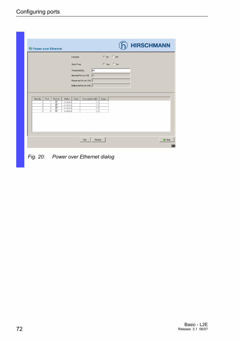
V Select the dialog Basics: Power over Ethernet.V With “Function On/Off” you turn PoE either on or off.V “Send trap” allows the switch to send a trap in the following cases:
– Whenever a value exceeds or falls below the performance threshold. – When switching the PoE supply voltage on or off on at least one port.
V Enter the power threshold in “Threshold”. When this value is exceeded/not achieved, the switch will send a trap, provided that “Send trap” is enabled. You enter the power threshold as a percentage of the nominal power in relation to the power yielded.
V “Nominal Power” displays the performance that the switch nominally provides for all PoE ports together.
V “Reserved Power” displays the maximum power that the Switch provides to all the connected PoE devices together on the basis of their classification.
V “Delivered Power” indicates how large the current power requirement is at all PoE ports.
The difference between the “nominal” and “reserved” power indicates how much power is still available to the free PoE ports.
V In the “Port on” column, you can enable/disable the port.V The “Status” column indicates the PoE status of the port.V In the “Priority” column (MACH 4000), set the PoE priority of the port
to either low, high or critical. V The class of the connected device is indicated in the “Class” column:
Class Maximum power provided 0 15.4 W = State on delivery 1 4.0 W 2 7.0 W 3 15.4 W 4 reserved, treat as class 0
V The “Name” column indicates the name of the port, see Basic settings:Port configuration.
Basic - L2ERelease 3.1 06/07 71
Configuring ports
Fig. 20: Power over Ethernet dialog
72Basic - L2E
Release 3.1 06/07

Protection from unauthorized access
6 Protection from unauthorized access
Protect your network from unauthorized access. The Switch provides you with the following functions for protecting against unauthorized access.
D Password for SNMP access,D Setting the Telnet/Web-Based access,D Disabling the HiDiscovery function,D Port access control via IP- or MAC-address,
Basic - L2ERelease 3.1 06/07 73
Protection from unauthorized access 6.1 Password for SNMP access
6.1 Password for SNMP access
6.1.1 Description Password for SNMP access
A network management station communicates with the Switch via the Simple Network Management Protocol. Every SNMP packet contains the IP address of the sending computer and the password under which the sender of the packet wants to access the Switch MIB.
The Switch receives the SNMP packet and compares the IP address of the sending computer and the password with the entries in the MIB of the Switch (see “Management Information BASE MIB” on page 190). If the password has the appropriate access right, and if the IP address of the sending com-puter has been entered, then the Switch will allow access.
In the delivery state, the Switch is accessible via the “public” password (read only) and the “private” one (read and write) from every computer.
To protect your Switch from unwanted access:
V First define a new password which you can access from your computer with all rights.
V Treat this community with discretion. Because everyone who knows the password can access the Switch MIB with the IP address of your computer.
V Limit the access rights of the known passwords or delete their entries.
74Basic - L2E
Release 3.1 06/07
Protection from unauthorized access 6.1 Password for SNMP access
6.1.2 Entering password for SNMP access
V Select the Security:Password / SNMPv3 access dialog. This dialog gives you the option of changing the read and read/write passwords for access to the Switch via Web-based Interface/CLI/SNMP. Please note that passwords are case-sensitive. For security reasons, the read password and the read/write pass-word must not be identical.
V The Web-based Interface and the User Interface communicate via SNMP version 3.
V Select "Modify read-only password" to enter the read-only password.
V Enter the new read-only password in the line "New password" and re-peat the entry in the line “Please retype".
V Select "Modify read-write password" to enter the read-write pass-word.
V Enter the new read-write password in the line "New password" and repeat the entry in the line “Please retype”.
Basic - L2ERelease 3.1 06/07 75

Protection from unauthorized access 6.1 Password for SNMP access
Fig. 21: Password dialog
Important: If you do not know a password with read/write access, you will not have write access to the Switch!
Note: After changing the password for write access, restart the Web in-terface in order to access the Switch.
Note: For security reasons, the passwords are not displayed. Make a note of every change! You cannot access the Switch without a valid password!
Note: For security reasons, SNMP version 3 encrypts the password. With the setting SNMPv1 or SNMPv2 in the Security:SNMPv1/v2 Access dialog, the password becomes readable again.
Note: In SNMP version 3, use 5 up to 32 characters for the password, because many applications do not accept shorter passwords.
76Basic - L2E
Release 3.1 06/07
Protection from unauthorized access 6.1 Password for SNMP access
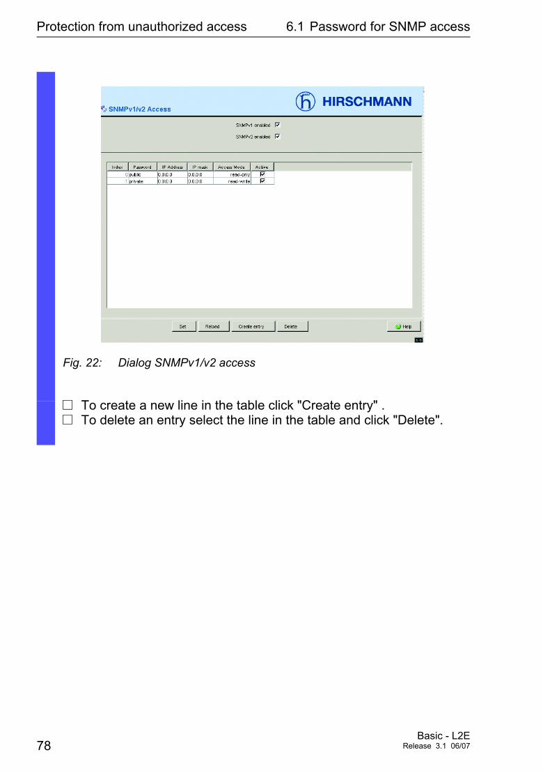
V Select the Security:SNMPv1/v2 Access dialog. This dialog gives you the option to select the access via SNMPv1 or SNMPv2. In the state on delivery both protocols are enabled. Thus you can manage the Switch via HiVision and communicate with earlier versions of SNMP.
Please note that passwords are case-sensitive. Select “SNMPv1/2c on” to be able to communicate with earlier versions of SNMP. If you select SNMPv1 or SNMPv2 in the table you can determine which IP addresses are allowed to access the Switch and which kind of pass-words are to be used. The table allows up to 8 entries. For security reasons, the read password and the read/write password must not be identical. Please note that passwords are case-sensitive.
Index Current number for this table entryPassword Password, the computer has to use, to have access to the Switch. This
password is indepentent of the SNMPv3 password.IP address IP address of the computer that is allowed to access the Switch.IP mask IP mask to the IP address.Access Mode Access Mode determines if the computer has read-only or read-write
access.Active Enabling/Disabling this table entry.
Basic - L2ERelease 3.1 06/07 77
Protection from unauthorized access 6.1 Password for SNMP access
Fig. 22: Dialog SNMPv1/v2 access
V To create a new line in the table click "Create entry" .V To delete an entry select the line in the table and click "Delete".
78Basic - L2E
Release 3.1 06/07
Protection from unauthorized access 6.2 Setting Telnet/Web access
6.2 Setting Telnet/Web access
6.2.1 Description Telnet/Web access
The Telnet server of the Switch allows you to configure the Switch using the Command Line Interface (in-band). You can switch off the Telnet server to prevent Telnet access to the Switch. In the state of delivery, the server is switched on.
After the Telnet server has been switched off, a new access to the Switch with a Telnet connection is not possible. An existing Telnet connection remains.
Note: The command line interface (out-of-band) and the Security:Tel net/Web Access dialog in the Web-based Interface allow you to to activate the telnet server again.
6.2.2 Description Web access
The Web server of the Switch allows you to configure the Switch using the Web-based interface. You can switch off the Web server to prevent Web access to the Switch. In the state of delivery, the server is switched on.
After the Web server has been switched off, a new logon with a Web browser is not possible. The logon in the opened browser window keeps active.
Note: The command line interface allows you to activate the Web server again.
Basic - L2ERelease 3.1 06/07 79
Protection from unauthorized access 6.2 Setting Telnet/Web access
6.2.3 Enabling/disabling Telnet/Web access
V Select the Security:Telnet/Web Access dialog.
V Switch off the server to which you wish to disable access.
V Enter the command enable to switch to the privileged EXEC mode.
V Enter the command transport input telnet to switch on the telnet server.
V Enter the command no transport input telnet to switch off the telnet server.
V Enter the command ip http server to switch on the Web server.
V Enter the command no ip http server to switch off the Web server.
80Basic - L2E
Release 3.1 06/07

Protection from unauthorized access 6.3 Disabling HiDiscovery function
6.3 Disabling HiDiscovery function
6.3.1 Description HiDiscovery protocol
The HiDiscovery protocol (see “Entering the IP parameters via HiDiscovery” on page 35) allows you to assign an IP address to the Switch on the basis of its MAC address. HiDiscovery is a layer 2 protocol.
Note: For security reasons, either limit or switch off completely the HiDisco-very function of the Switch after assigning the IP parameters.
Basic - L2ERelease 3.1 06/07 81
Protection from unauthorized access 6.3 Disabling HiDiscovery function
6.3.2 Disabling HiDiscovery function
V Select the Basics:Network. dialog.
V Switch off the HiDiscovery function in the “HiDiscovery Protocol” frame, or limit access to “read-only”.
V Enter the command enable to switch to the privileged EXEC mode.
V Enter the command network protocol hidiscovery off to switch off the HiDiscovery function.
V Enter the command network protocol hidiscovery read-only to switch on.the HiDiscovery function with the read-only access right.
V Enter the commandnetwork protocol hidiscovery read-write to switch on the HiDiscovery function with the read-write access right.
82Basic - L2E
Release 3.1 06/07
Protection from unauthorized access 6.4 Port access control
6.4 Port access control
6.4.1 Description port access control
The Switch protects every port from unauthorized access. Depending of your choice the Switch checks the MAC address or the IP address of the connected device. The following functions are available for monitoring every individual port:
D Who has access to this port?The Switch recognizes 2 classes of access control: – All: no access restriction
MAC address 00:00:00:00:00:00 oder IP address 0.0.0.0.
– User: only an assigned user has access. the user you define by his MAC address or his
IP address.
D What should happen after an unauthorized access attempt?The Switch can respond in three selectable ways to an unauthorized access attempt: – non: no response – trapOnly: message by sending a trap – portDisable: message by sending a trap and
disabling a port
Note: Since the Switch is a layer 2 device, it translates the stored IP addres-ses into MAC addresses. This requires that a MAC address be assigned to exactly one IP address. Please keep in mind that when using a router, several IP addresses can be assigned to one MAC address, namely that of the router. This means that all packets of the router will pass the port unchecked if the permitted IP address is that of the router. If a connected device sends packets with other MAC addresses and a per-mitted IP address, the Switch will disable the port.
Basic - L2ERelease 3.1 06/07 83
Protection from unauthorized access 6.4 Port access control
6.4.2 Defining port access control
V Select the Security:Port Security dialog.
V First select, whether you wish the MAC based or the IP based port security.
V If you have selected MAC based you enter in the “Allowed MAC addresses” column the the MAC addresses of the devices with which a data exchange at this port is permitted. You can enter up to 10 MAC addresses each ot these seperated with a space character. Without entry, reception from all devices is allowed.
D The “Current MAC address” column shows the MAC address of the device from which data was last received. By pressing the left mouse button, you can copy an entry from the “Current MAC address” column into the “Allowed MAC address” column.
V If you selected IP based, enter in the column “Allowed IP addesses” the IP addresses of the devices, with which data exchange at this port is allowed. You can enter up to 10 IP addresses each ot these seperated with a space character. Without entry, reception from all devices is allowed.
V In the “Action” column you select whether an unauthorized access at-tempt should be followed by – no action (none) or – the sending of an alarm (trapOnly) or – switching off the port by making a corresponding entry in the port configuration table (see “Configuring ports” on page 69) and sending an alarm (trap) (portDisable).
84Basic - L2E
Release 3.1 06/07
Protection from unauthorized access 6.4 Port access control
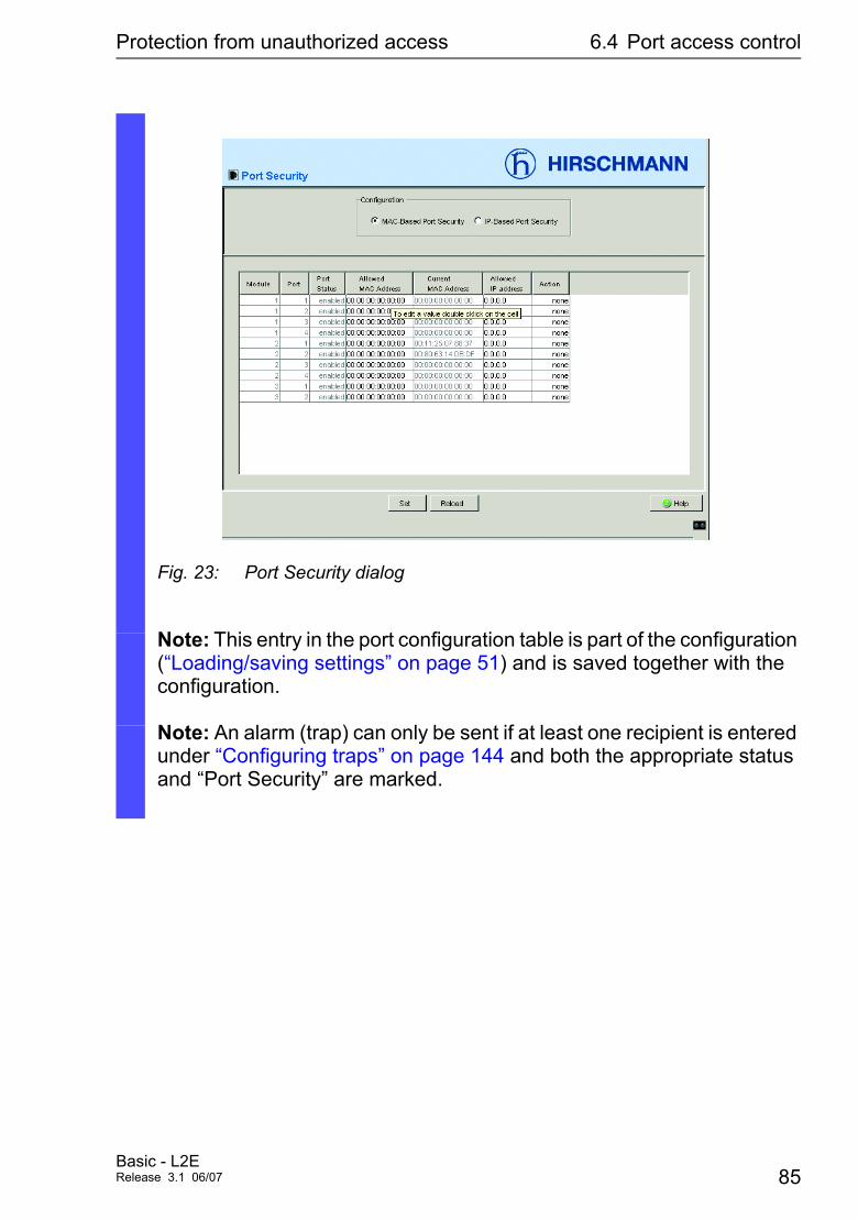
Fig. 23: Port Security dialog
Note: This entry in the port configuration table is part of the configuration (“Loading/saving settings” on page 51) and is saved together with the configuration.
Note: An alarm (trap) can only be sent if at least one recipient is entered under “Configuring traps” on page 144 and both the appropriate status and “Port Security” are marked.
Basic - L2ERelease 3.1 06/07 85

Protection from unauthorized access 6.4 Port access control
86Basic - L2E
Release 3.1 06/07
Synchronizing the System Time of the
7 Synchronizing the System Time of the Network
The real meaning of the term real time depends on the time requirements of the application.
The Switch provides two options with different levels of accuracy for synchronizing the time in your network.
If you only require accuracies in the order of milliseconds, the Simple Net-work Time Protocol (SNTP) offers a low-cost solution. Accuracy depends on signal running time. Areas of application of this protocol are: – log entries, – time stamping of production data, – production control, etc.
The Precision Time Protocol (PTP), which is described in the IEEE 1588 standard, achieves accuracies in the order of fractions of microseconds. This superior method is suitable for process control, for example.
Choose the protocol which best meets your requirements. When using both protocols at the same time, bear in mind that they interact.
Basic - L2ERelease 3.1 06/07 87
Synchronizing the System Time of the 7.1 Entering the Time
7.1 Entering the Time
If there is no reference clock available, you can enter the system time in the Switch so that you can use it like a reference clock (see “PTP Global” on page 99 and “Configuring SNTP” on page 92).
V Select the Time dialog.
This dialog offers you the option of making time-related settings inde-pendent of the selected time syncronization protocol.
D The “IEEE 1588 time” displays the time received via PTP. The “SNTP time” displays the time with reference to Universal Time Coordinated (UTC). The display is the same worldwide. Local time differences are not taken into account.
D The “System time” uses “IEEE 1588 / SNTPtime”, allowing for the lo-cal time difference from “IEEE 1588 / SNTPtime”. “System time” = “IEEE 1588 / SNTPtime” + “Local offset”
D „Time Source“ displays the origin of the following time. The Switch automatically selects the source with the highest precision.
V With “Set time from PC”, the Switch takes the PC time as the system time and calculates the IEEE 1588 / SNTP time using the local time difference. “IEEE 1588 / SNTP time” = “System time” - “Local offset”
V “Local Offset” is for displaying/entering the time difference between the local time and the “IEEE 1588 / SNTPtime” With “Set offset from PC”, the Switch determines the time zone on your PC and then calculates the local time difference.
Note: When setting the time in zones with summer and winter times, make an adjustment for the local offset. The Switch can also get the SNTP server IP address and the local offset from a DHCP server.
88Basic - L2E
Release 3.1 06/07

Synchronizing the System Time of the 7.1 Entering the Time
V Enter the command enable to switch to the privileged EXEC mode.V Enter the command configure to change to the configuration mo-
de.V Enter the command sntp time <YYYY-MM-DD HH:MM:SS> to set
the Switch system time.V Enter the command sntp client offset <-1000 to 1000> to
enter the time offset between local time and “IEEE1588/SNTP Time”.
Basic - L2ERelease 3.1 06/07 89
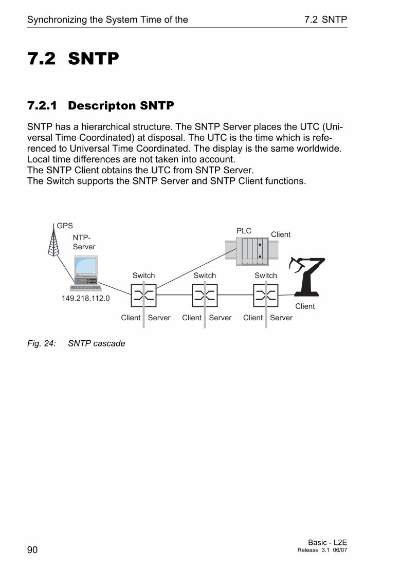
Synchronizing the System Time of the 7.2 SNTP
7.2 SNTP
7.2.1 Descripton SNTP
SNTP has a hierarchical structure. The SNTP Server places the UTC (Uni-versal Time Coordinated) at disposal. The UTC is the time which is refe-renced to Universal Time Coordinated. The display is the same worldwide. Local time differences are not taken into account. The SNTP Client obtains the UTC from SNTP Server. The Switch supports the SNTP Server and SNTP Client functions.
Fig. 24: SNTP cascade
GPS
NTP-
Server
ServerClient
Client
Client
Switch
PLC
ServerClient
Switch
ServerClient
Switch
149.218.112.0
90Basic - L2E
Release 3.1 06/07
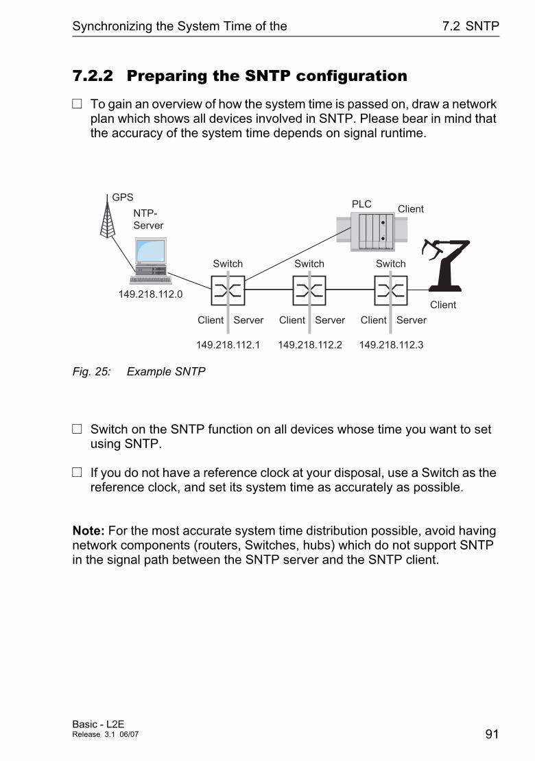
Synchronizing the System Time of the 7.2 SNTP
7.2.2 Preparing the SNTP configuration
V To gain an overview of how the system time is passed on, draw a network plan which shows all devices involved in SNTP. Please bear in mind that the accuracy of the system time depends on signal runtime.
Fig. 25: Example SNTP
V Switch on the SNTP function on all devices whose time you want to set using SNTP.
V If you do not have a reference clock at your disposal, use a Switch as the reference clock, and set its system time as accurately as possible.
Note: For the most accurate system time distribution possible, avoid having network components (routers, Switches, hubs) which do not support SNTP in the signal path between the SNTP server and the SNTP client.
GPS
NTP-
Server
ServerClient
Client
Client
Switch
PLC
ServerClient
Switch
ServerClient
Switch
149.218.112.1 149.218.112.2 149.218.112.3
149.218.112.0
Basic - L2ERelease 3.1 06/07 91
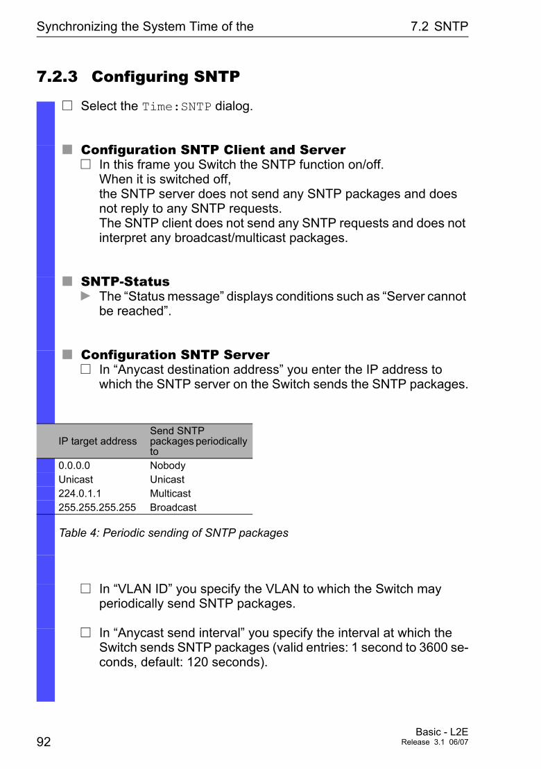
Synchronizing the System Time of the 7.2 SNTP
7.2.3 Configuring SNTP
V Select the Time:SNTP dialog.
U Configuration SNTP Client and ServerV In this frame you Switch the SNTP function on/off.
When it is switched off, the SNTP server does not send any SNTP packages and does not reply to any SNTP requests. The SNTP client does not send any SNTP requests and does not interpret any broadcast/multicast packages.
U SNTP-StatusD The “Status message” displays conditions such as “Server cannot
be reached”.
U Configuration SNTP ServerV In “Anycast destination address” you enter the IP address to
which the SNTP server on the Switch sends the SNTP packages.
IP target address Send SNTP packages periodically to
0.0.0.0 NobodyUnicast Unicast224.0.1.1 Multicast255.255.255.255 Broadcast
Table 4: Periodic sending of SNTP packages
V In “VLAN ID” you specify the VLAN to which the Switch may periodically send SNTP packages.
V In “Anycast send interval” you specify the interval at which the Switch sends SNTP packages (valid entries: 1 second to 3600 se-conds, default: 120 seconds).
92Basic - L2E
Release 3.1 06/07
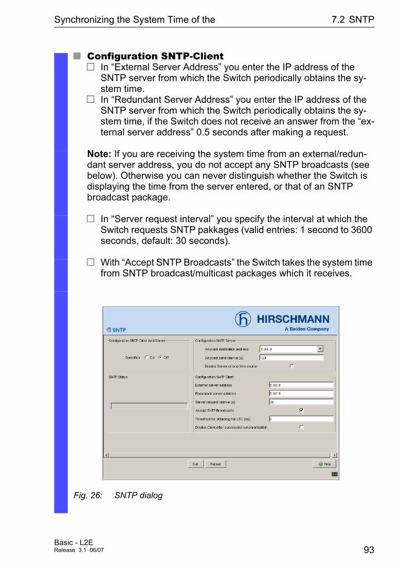
Synchronizing the System Time of the 7.2 SNTP
U Configuration SNTP-ClientV In “External Server Address” you enter the IP address of the
SNTP server from which the Switch periodically obtains the sy-stem time.
V In “Redundant Server Address” you enter the IP address of the SNTP server from which the Switch periodically obtains the sy-stem time, if the Switch does not receive an answer from the “ex-ternal server address” 0.5 seconds after making a request.
Note: If you are receiving the system time from an external/redun-dant server address, you do not accept any SNTP broadcasts (see below). Otherwise you can never distinguish whether the Switch is displaying the time from the server entered, or that of an SNTP broadcast package.
V In “Server request interval” you specify the interval at which the Switch requests SNTP pakkages (valid entries: 1 second to 3600 seconds, default: 30 seconds).
V With “Accept SNTP Broadcasts” the Switch takes the system time from SNTP broadcast/multicast packages which it receives.
Fig. 26: SNTP dialog
Basic - L2ERelease 3.1 06/07 93

Synchronizing the System Time of the 7.2 SNTP
Switch 149.218.112.1 149.218.112.2 149.218.112.3Function on on onAnycast destination address 0.0.0.0 0.0.0.0 0.0.0.0Server VLAN ID 1 1 1Anycast send interval 120 120 120Client External server address 149.218.112.0 149.218.112.1 149.218.112.2Server request interval 30 30 30Accept SNTP Broadcasts no no no
Tab. 5: Settings for the example (see Fig. 32)
94Basic - L2E
Release 3.1 06/07
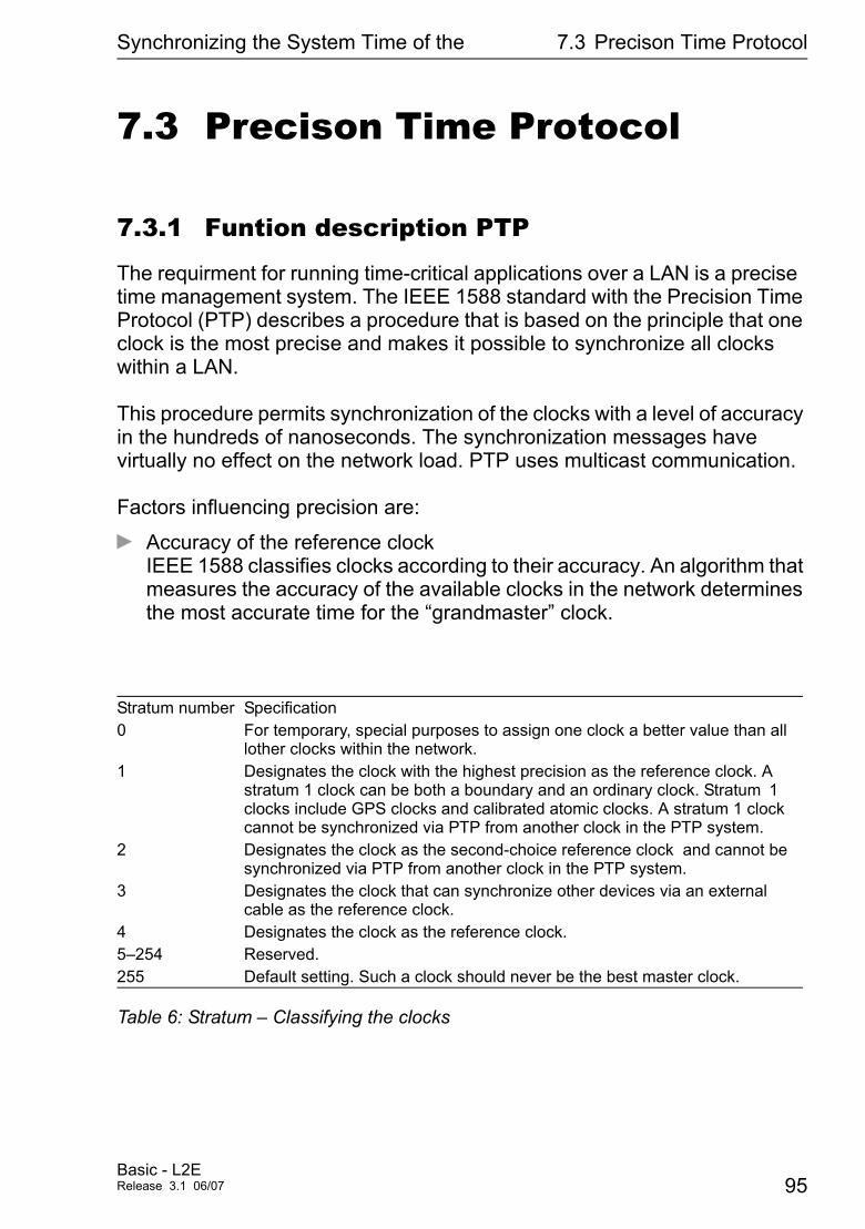
Synchronizing the System Time of the 7.3 Precison Time Protocol
7.3 Precison Time Protocol
7.3.1 Funtion description PTP
The requirment for running time-critical applications over a LAN is a precise time management system. The IEEE 1588 standard with the Precision Time Protocol (PTP) describes a procedure that is based on the principle that one clock is the most precise and makes it possible to synchronize all clocks within a LAN.
This procedure permits synchronization of the clocks with a level of accuracy in the hundreds of nanoseconds. The synchronization messages have virtually no effect on the network load. PTP uses multicast communication.
Factors influencing precision are:
D Accuracy of the reference clock IEEE 1588 classifies clocks according to their accuracy. An algorithm that measures the accuracy of the available clocks in the network determines the most accurate time for the “grandmaster” clock.
Stratum number Specification0 For temporary, special purposes to assign one clock a better value than all
lother clocks within the network.1 Designates the clock with the highest precision as the reference clock. A
stratum 1 clock can be both a boundary and an ordinary clock. Stratum 1 clocks include GPS clocks and calibrated atomic clocks. A stratum 1 clock cannot be synchronized via PTP from another clock in the PTP system.
2 Designates the clock as the second-choice reference clock and cannot be synchronized via PTP from another clock in the PTP system.
3 Designates the clock that can synchronize other devices via an external cable as the reference clock.
4 Designates the clock as the reference clock.5–254 Reserved.255 Default setting. Such a clock should never be the best master clock.
Table 6: Stratum – Classifying the clocks
Basic - L2ERelease 3.1 06/07 95
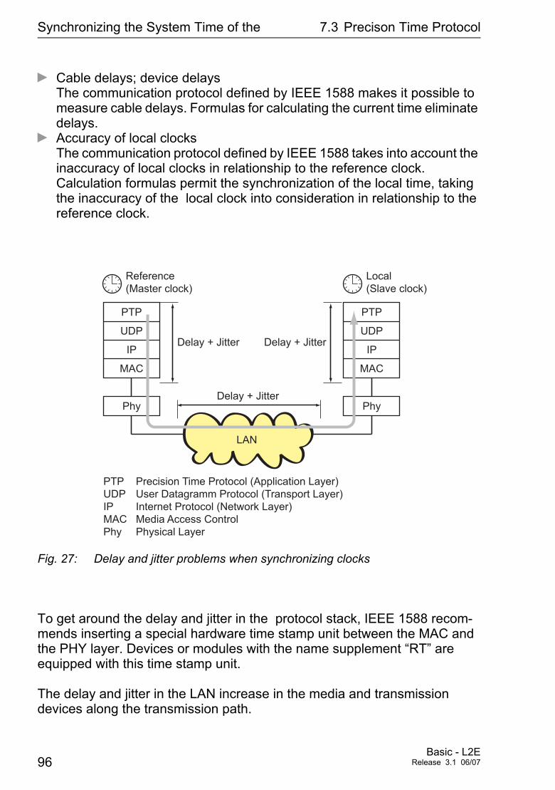
Synchronizing the System Time of the 7.3 Precison Time Protocol
D Cable delays; device delays The communication protocol defined by IEEE 1588 makes it possible to measure cable delays. Formulas for calculating the current time eliminate delays.
D Accuracy of local clocks The communication protocol defined by IEEE 1588 takes into account the inaccuracy of local clocks in relationship to the reference clock. Calculation formulas permit the synchronization of the local time, taking the inaccuracy of the local clock into consideration in relationship to the reference clock.
Fig. 27: Delay and jitter problems when synchronizing clocks
To get around the delay and jitter in the protocol stack, IEEE 1588 recom-mends inserting a special hardware time stamp unit between the MAC and the PHY layer. Devices or modules with the name supplement “RT” are equipped with this time stamp unit.
The delay and jitter in the LAN increase in the media and transmission devices along the transmission path.
PTP
Reference
(Master clock)
UDP
IP
MAC
Phy
PTP
UDP
IP
MAC
Phy
Local
(Slave clock)
LAN
PTP Precision Time Protocol (Application Layer)
UDP User Datagramm Protocol (Transport Layer)
IP Internet Protocol (Network Layer)
MAC Media Access Control
Phy Physical Layer
Delay + Jitter
Delay + Jitter Delay + Jitter
96Basic - L2E
Release 3.1 06/07
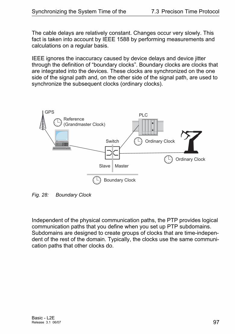
Synchronizing the System Time of the 7.3 Precison Time Protocol
The cable delays are relatively constant. Changes occur very slowly. This fact is taken into account by IEEE 1588 by performing measurements and calculations on a regular basis.
IEEE ignores the inaccuracy caused by device delays and device jitter through the definition of “boundary clocks”. Boundary clocks are clocks that are integrated into the devices. These clocks are synchronized on the one side of the signal path and, on the other side of the signal path, are used to synchronize the subsequent clocks (ordinary clocks).
Fig. 28: Boundary Clock
Independent of the physical communication paths, the PTP provides logical communication paths that you define when you set up PTP subdomains. Subdomains are designed to create groups of clocks that are time-indepen-dent of the rest of the domain. Typically, the clocks use the same communi-cation paths that other clocks do.
GPS
Reference
(Grandmaster Clock)
MasterSlave
Boundary Clock
Ordinary Clock
Ordinary Clock
Switch
PLC
Basic - L2ERelease 3.1 06/07 97
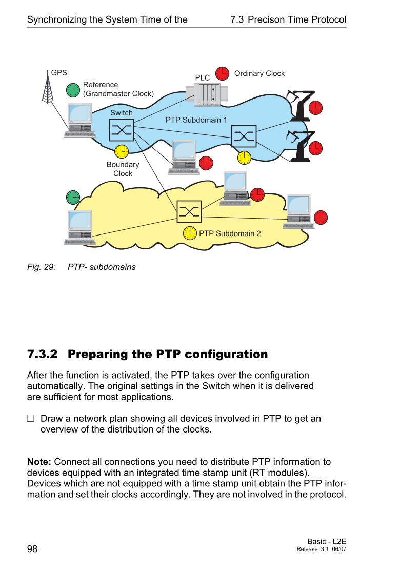
Synchronizing the System Time of the 7.3 Precison Time Protocol
Fig. 29: PTP- subdomains
7.3.2 Preparing the PTP configuration
After the function is activated, the PTP takes over the configuration automatically. The original settings in the Switch when it is delivered are sufficient for most applications.
V Draw a network plan showing all devices involved in PTP to get an overview of the distribution of the clocks.
Note: Connect all connections you need to distribute PTP information to devices equipped with an integrated time stamp unit (RT modules). Devices which are not equipped with a time stamp unit obtain the PTP infor-mation and set their clocks accordingly. They are not involved in the protocol.
GPS
Reference
(Grandmaster Clock)
Boundary
Clock
Ordinary Clock
Switch
PTP Subdomain 2
PTP Subdomain 1
PLC
98Basic - L2E
Release 3.1 06/07
Synchronizing the System Time of the 7.3 Precison Time Protocol
V Switch on the PTP function on all devices whose time you want to syn-chronize using PTP.
V If there is no reference clock available, designate a Switch as reference clock, and set the system time as precisely as possible.
7.3.3 Configuring PTP
In the dialog Time:PTP:Global, you can enable/disable the function and make the PTP settings on the devices MS20/30 and Power MICE which are to apply to all ports.
U PTP GlobalV Select the Time:PTP:Global dialog.V Switch on the function in the “Operation IEEE 1588 / PTP” frame.V If you have designated this Switch to be the PTP reference clock,
click in the “Configuration IEEE 1588 / PTP” frame in the “Prefer-red Master” line the value “true”.
D By selecting “Reinitialize” you restart the synchronization of the local clock.
D ConfigurationClock Mode: Mode of the local clock. Possible options are: – ptp-mode-Boundary-clock, – ptp-mode-simple-ptp (without runtime correction, without determining the best clock) Select this mode, if the Switch has no time stamp unit (RT module).
Preferred Master: Defines the local clock as the Preferred Master.
Basic - L2ERelease 3.1 06/07 99
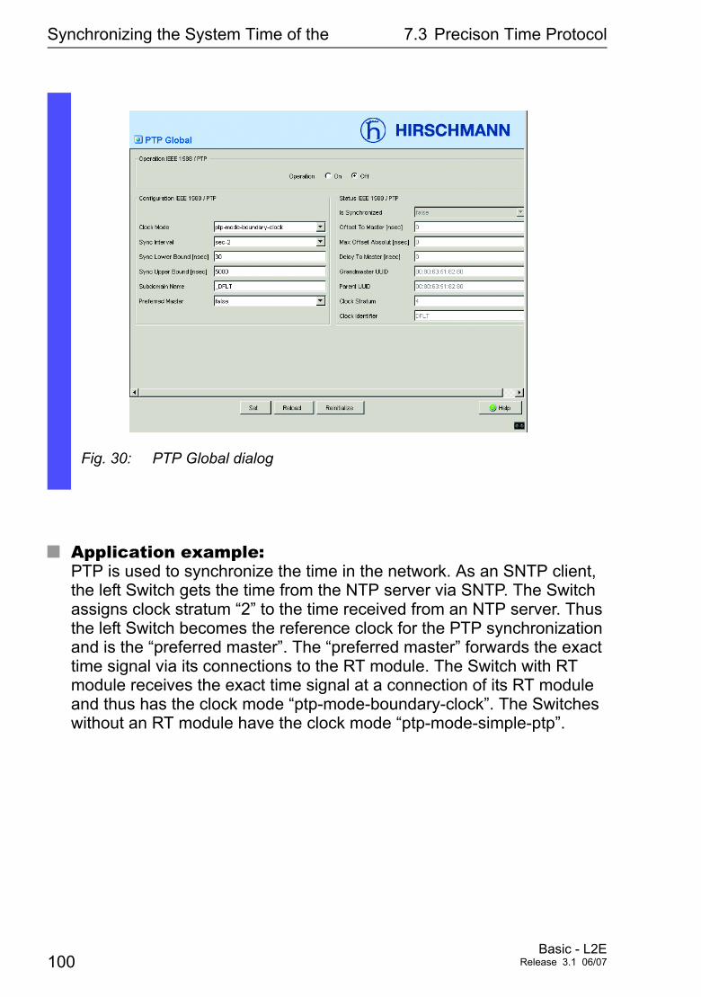
Synchronizing the System Time of the 7.3 Precison Time Protocol
U Application example:PTP is used to synchronize the time in the network. As an SNTP client, the left Switch gets the time from the NTP server via SNTP. The Switch assigns clock stratum “2” to the time received from an NTP server. Thus the left Switch becomes the reference clock for the PTP synchronization and is the “preferred master”. The “preferred master” forwards the exact time signal via its connections to the RT module. The Switch with RT module receives the exact time signal at a connection of its RT module and thus has the clock mode “ptp-mode-boundary-clock”. The Switches without an RT module have the clock mode “ptp-mode-simple-ptp”.
Fig. 30: PTP Global dialog
100Basic - L2E
Release 3.1 06/07
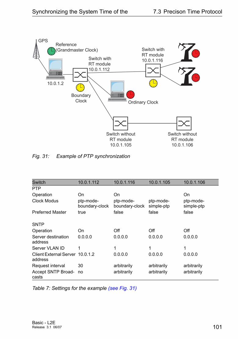
Synchronizing the System Time of the 7.3 Precison Time Protocol
Fig. 31: Example of PTP synchronization
Switch 10.0.1.112 10.0.1.116 10.0.1.105 10.0.1.106PTPOperation On On OnClock Modus ptp-mode-
boundary-clockptp-mode-boundary-clock
ptp-mode-simple-ptp
ptp-mode-simple-ptp
Preferred Master true false false false
SNTPOperation On Off Off OffServer destination address
0.0.0.0 0.0.0.0 0.0.0.0 0.0.0.0
Server VLAN ID 1 1 1 1Client External Server address
10.0.1.2 0.0.0.0 0.0.0.0 0.0.0.0
Request interval 30 arbitrarily arbitrarily arbitrarilyAccept SNTP Broad-casts
no arbitrarily arbitrarily arbitrarily
Table 7: Settings for the example (see Fig. 31)
GPSReference(Grandmaster Clock)
BoundaryClock Ordinary Clock
Switch withRT module 10.0.1.112
Switch withRT module 10.0.1.116
Switch withoutRT module10.0.1.105
Switch withoutRT module10.0.1.106
10.0.1.2
Basic - L2ERelease 3.1 06/07 101
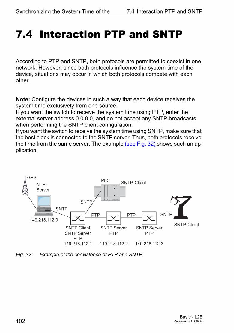
Synchronizing the System Time of the 7.4 Interaction PTP and SNTP
7.4 Interaction PTP and SNTP
According to PTP and SNTP, both protocols are permitted to coexist in one network. However, since both protocols influence the system time of the device, situations may occur in which both protocols compete with each other.
Note: Configure the devices in such a way that each device receives the system time exclusively from one source. If you want the switch to receive the system time using PTP, enter the external server address 0.0.0.0, and do not accept any SNTP broadcasts when performing the SNTP client configuration. If you want the switch to receive the system time using SNTP, make sure that the best clock is connected to the SNTP server. Thus, both protocols receive the time from the same server. The example (see Fig. 32) shows such an ap-plication.
Fig. 32: Example of the coexistence of PTP and SNTP.
GPS
NTP-
Server
SNTP Client
SNTP Server
PTP
SNTP Server
PTP
SNTP Server
PTP
SNTP-Client
SNTP-Client
PLC
PTP
SNTP
SNTP
SNTPPTP
149.218.112.1 149.218.112.2 149.218.112.3
149.218.112.0
102Basic - L2E
Release 3.1 06/07
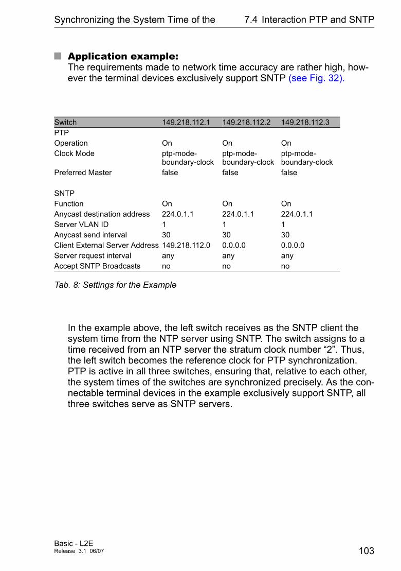
Synchronizing the System Time of the 7.4 Interaction PTP and SNTP
U Application example:The requirements made to network time accuracy are rather high, how-ever the terminal devices exclusively support SNTP (see Fig. 32).
In the example above, the left switch receives as the SNTP client the system time from the NTP server using SNTP. The switch assigns to a time received from an NTP server the stratum clock number “2”. Thus, the left switch becomes the reference clock for PTP synchronization. PTP is active in all three switches, ensuring that, relative to each other, the system times of the switches are synchronized precisely. As the con-nectable terminal devices in the example exclusively support SNTP, all three switches serve as SNTP servers.
Switch 149.218.112.1 149.218.112.2 149.218.112.3PTPOperation On On OnClock Mode ptp-mode-
boundary-clockptp-mode-boundary-clock
ptp-mode-boundary-clock
Preferred Master false false false
SNTPFunction On On OnAnycast destination address 224.0.1.1 224.0.1.1 224.0.1.1Server VLAN ID 1 1 1Anycast send interval 30 30 30Client External Server Address 149.218.112.0 0.0.0.0 0.0.0.0Server request interval any any anyAccept SNTP Broadcasts no no no
Tab. 8: Settings for the Example
Basic - L2ERelease 3.1 06/07 103

Synchronizing the System Time of the 7.4 Interaction PTP and SNTP
104Basic - L2E
Release 3.1 06/07

Traffic control
8 Traffic control
To optimize the data transmission, the Switch provides you with the following functions for controlling the network load:
D Settings for directed frame forwarding (MAC address filter)D Multicast settingsD Rate LimiterD PrioritizationD Flow controlD Virtual LANs
Basic - L2ERelease 3.1 06/07 105
Traffic control 8.1 Directed frame forwarding
8.1 Directed frame forwarding
Directed frame forwarding is a method used by the Switch to avoid unneces-sary increases in the network load. The Switch features the following directed frame forwarding functions:
D Store-and-forwardD Multiadress capabilityD Aging of learned addressesD Static address entriesD Disabling the specific packet distribution
8.1.1 Store-and-forward
All data received by the Switch is stored, and its validity is checked. Invalid and defective data packets (> 1,522 Bytes or CRC errors) as well as frag-ments (< 64 Bytes) are discarded. Valid data packets are forwarded by the Switch.
8.1.2 Multi-address capability
The Switch learns all the source addresses for a port. Only packets with
D unknown addressesD these addresses orD a multi/broadcast address
in the destination address field are sent to this port. The Switch enters learned source addresses in its filter table (see “Entering static address ent-ries” on page 108).
106Basic - L2E
Release 3.1 06/07
Traffic control 8.1 Directed frame forwarding
The Switch can learn up to 8000 addresses. This becomes necessary if more than one terminal device is connected to one or more ports. It is thus possible to connect several independent subnetworks to the Switch.
8.1.3 Aging of learned addresses
The Switch monitors the age of the learned addresses. Address entries which exceed a certain age (30 seconds, aging time) are deleted by the Switch from its address table.The Switch floods data packets with an unknown target address. The Switch transmits data pakets with known target addresses to specific destinations.
Note: A reboot deletes the learned address entries.
V Select the Switching:Global dialog.
V Enter the Aging Time for all dynamic entries in the range from 10 to 630 seconds (Unit: 1 second, default setting: 30). In connection with the router redundancy (see MACH 3000), set the time greater/equal than 30 seconds.
Basic - L2ERelease 3.1 06/07 107
Traffic control 8.1 Directed frame forwarding
8.1.4 Entering static address entries
One of the most important functions of a Switch is the filter function. It selects data packets according to certain defined patterns called filters. These patterns are associated with switching rules. This means that a data packet received at the port of a Switch is compared to the patterns. If there is a pattern which matches the data packet, the Switch will either transmit or re-ject the packet according to the switching rules for the affected ports.
The following are valid filter criteria:
D Destination address,D Broadcast address,D Multicast address,D VLAN membership.
The individual filters are stored in the filter table (Forwarding Database, FDB). The table has three parts, a static part and two dynamic parts.
D The management administrator describes the static part of the filter table (dot1qStaticTable).
D During operation, the Switch is capable of learning which ports will receive data packets from which source addresses (see “Multi-address capability” on page 106). This information is stored in the dynamic part of the table (dot1qTpFdbTable).
D Addresses learned from the neighbouring agent and those learned by GMRP are written to another dynamic part.
Addresses already located in the static filter table, are automatically transferred by a Switch into the dynamic part. An address entered statically cannot be overwritten through learning.
Note: If the redundancy manager is active, it is not possible to make perma-nent unicast entries.
Note: In the filtering database you can create up to 100 filter for multicast addresses.
108Basic - L2E
Release 3.1 06/07
Traffic control 8.1 Directed frame forwarding
8.1.5 Disabling the specific packet distribution
To enable you to observe the data at all the ports, the Switch allows you to disable the learning of addresses. When the learning of addresses is disabled, the Switch transfers all the data from all ports to all ports.
V Select the Switching:Filter for MAC addresses dialog.
In the filtering table each row represents one filter. Filters specify the way in which data packets are sent. They are set automatically by the Switch (learned status) or manually. Data packets whose destination addresses are entered in the table are sent from the receiving port to the ports marked in the table. Data packets whose destination addresses are not in the table are sent from the receiving port to all other ports. In the “Create static entry” dialog you can set up new filters. The following status settings are possible:
D learned: the filter was created automatically by the Switch.D invalid: with this status you delete a manually created filter.D permanent: the filter is stored permanently in the Switch or on the
URL (see “Saving settings” on page 57).D gmrp: the filter was created by GMRP.D gmrp/permanent: GMRP added further port markings to the filter
after it was created by the administrator. The port markings added by the GMRP are deleted by a restart.
D igmp: the filter was created by IGMP.
V To delete entries with the status “learned” from the filtering table select the Basics:Restart dialog and click on “Reset MAC address table”.
V Select the Switching:global dialog.
V Checkmark “Address Learning” to observe the data of all ports.
Basic - L2ERelease 3.1 06/07 109
Traffic control 8.2 Multicast application
8.2 Multicast application
8.2.1 Description multicast application
The data distribution in the LAN distinguishes between three distribution classes with reference to the addressed recipient:
D Unicast - one recipientD Multicast - a group of recipientsD Broadcast - every recipient that can be reached
In the case of a Multicast address, Switches pass on all the data packets with a Multicast address to all the ports. This leads to an increased bandwidth re-quirement. Protocols such as GMRP and processes such as IGMP Snooping enable the Switches to exchange information by means of the targeted distribution of Multicast data packets. The distribution of the Multicast data packets exclu-sively to those ports to which the recipients of these Multicast data packets are connected, reduces the bandwith required.
You can recognize IGMP Multicast addresses by the area in which an address is located:
D MAC multicast address 01:00:5E:00:00:00 - 01:00:5E:FF:FF:FF
D IP multicast address class D 224.0.0.0 - 239.255.255.255
110Basic - L2E
Release 3.1 06/07
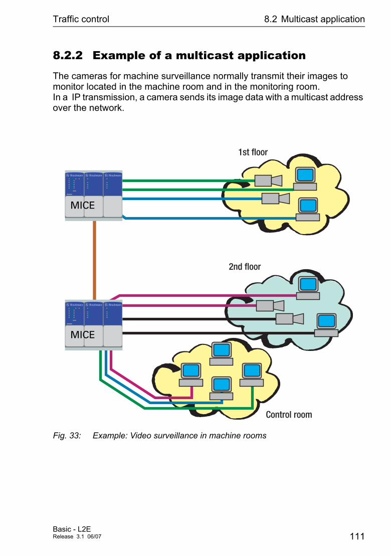
Traffic control 8.2 Multicast application
8.2.2 Example of a multicast application
The cameras for machine surveillance normally transmit their images to monitor located in the machine room and in the monitoring room.In a IP transmission, a camera sends its image data with a multicast address over the network.
Fig. 33: Example: Video surveillance in machine rooms
1st floor
Control room
2nd floor
MICE
h H h H h H
MICE
h H h H h H
Basic - L2ERelease 3.1 06/07 111
Traffic control 8.2 Multicast application
8.2.3 Description IGMP snooping
The Internet Group Management Protocol (IGMP) describes the distribution of Multicast information between routers and terminal devices on the Layer 3 level. Routers with an active IGMP function periodically send queries to find out which IP Multicast group members are connected to the LAN. Multicast group members reply with a Report message. This Report message contains all the parameters required by the IGMP. The router records the IP Multicast group address from the Report message in its routing table. The result of this is that it transfers frames with this IP Multicast group address in the target address field only in accordance with the routing table. Devices which no longer want to be members of a Multicast group can cancel their membership by means of a Leave message (from IGMP version 2), and they do not transmit any more Report messages. In IGMP versions 1 and 2, the router removes the routing table entry if it does not receive any Report messages within a specified period of time (aging time). If there are a number of routers with an active IGMP function in the network, then they work out among themselves which router carries out the Query function when using IGMP version 2. If there is no router in the network, then a suitably equipped Switch can carry out the Query function.
A Switch that connects a Multicast receiver with a router can evaluate the IGMP information with the aid of the IGMP Snooping procedure. IGMP Snooping translates IP Multicast group addresses into MAC Multicast addresses, so that the IGMP functions can also be used by Layer 2 Switches. The Switch records the MAC addresses of the Multicast receivers, which are obtained by the IGMP Snooping from the IP addresses, in the static address table. Thus the Switch blocks Multicast packets at the ports at which no Multicast receivers are connected.
8.2.4 Setting multicast applications
V Select the Switching:Multicasts dialog.
112Basic - L2E
Release 3.1 06/07
Traffic control 8.2 Multicast application
U Global ConfigurationWith “IGMP Snooping” check box you can switch IGMP Snooping on/off globally for the entire Switch. If IGMP Snooping is switched off, then:
D the Switch does not evaluate Query and Report packets received and
D it sends (floods) received data packets with a Multicast address as the target address to all ports.
U IGMP QuerierWith “IGMP Querier active” you can switch the Query function on/off. The Protocol check boxes allow you to select IGMP version 1, 2 or version 3.
U Unknown Multicasts"Send to Query Ports", the Switch sends the packets with an unknown MAC/IP multicast address to all query ports."Send to All Ports", the Switch sends the packets with an unknown MAC/IP multicast address to all ports."Discard", the Switch discards all packets with an unknown MAC/IP multicast address.
Note: The way in which unlearned multicast addresses are handled also applies to the reserved addresses from the "Local Network Con-trol Block" (224.0.0.0 - 224.0.0.255). This can have an effect on the higher-level routing protocol.
U IGMP on per portThis table column enables you to switch on/off the IGMP for each port when the global IGMP Snooping is switched on. When you switch off the IGMP at a port, no registrations can be made for this port.
Basic - L2ERelease 3.1 06/07 113
Traffic control 8.2 Multicast application
U IGMP Forward All per portThis column of the table allows you to switch on/off the IGMP Snoo-ping function “Forward All” when the global IGMP Snooping is swit-ched on. With the “Forward All” setting, the Switch forwards all the data packets with a Multicast address in the target address field to this port.
Note: If a number of routers are connected to a subnetwork, then you must use IGMP version 1, so that all the routers receive all the IGMP reports.
Note: If you use IGMP version 1 in a subnetwork, then you must also use IGMP version 1 in the entire network.
U Static Query PortA Switch sends IGMP report messages to the ports at which it receives IGMP queries. This column allows you to also send IGMP report messages to other selected ports.
U Learned Query PortA Switch sends IGMP report messages to the ports at which it receives IGMP queries. This column displays the ports on which the Switch has received IGMP queries.
Note: If the Switch is connected to a HIPER-Ring, in the case of a ring interruption you can ensure quick reconfiguration of the network for data packets with registered multicast target addresses by:
D switching on the IGMP at the ring ports and globally, andD switching on the “IGMP Forward All” per port on the ring ports.
114Basic - L2E
Release 3.1 06/07
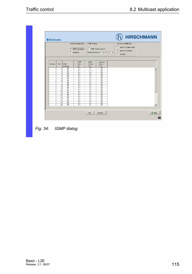
Traffic control 8.2 Multicast application
Fig. 34: IGMP dialog
Basic - L2ERelease 3.1 06/07 115
Traffic control 8.3 Rate Limiter
8.3 Rate Limiter
8.3.1 Description Rate Limiter
To guarantee reliable data exchange during high traffic, the Switch can limit traffic. Entering a limit rate for each port determines the amount of traffic the switch is permitted to transmit and receive. If the data load transmitted on this port exeeds the maximum load, the Switch will discard the excessive data on this port. A global setting activates/deactivates the rate limiter function at all ports.
8.3.2 Setting Rate Limiter for RS20/RS30/40, MS20/30, MACH 1000
V Select the Switching:Rate Limiter dialog.
With “Ingress Limiter” you can enable or disable the input limiting function for all ports.
With “Egress Limiter (p/s)” you can enable or disable the broadcast output limit on all ports.
With “Egress Limiter (kbit/s)” you can enable or disable the output limit for all packet types on all ports.
116Basic - L2E
Release 3.1 06/07
Traffic control 8.3 Rate Limiter
Setting options per port:
D “Ingress Packet Types” offers the option of selecting the packet type(s) for which the limit is to apply:D All, limits all packets received at this port.D BC, limits only broadcast packets received at this port.D BC + MC, limits broadcast packets and multicast packets received
at this port.D BC + MC + uUC, limits broadcast packets, multicast packets and
unknown unicast packets received at this port.
D Ingress Limiter Rate for the selected packet type(s):D = 0, no ingress limit at this port.D > 0, maximum inbound traffic rate (in kbit/s) that is allowed to be
received by and forwarded from this port.
D Egress Limiter rate for broadcast packets:D = 0, no rate limit for outbound broadcast packets at this port.D > 0, maximum broadcast rate that is sent on this port.
D Egress Limiter for all packet types:D = 0, no rate limit for outbound packets at this port.D > 0, maximum packet rate that is sent on this port.
Basic - L2ERelease 3.1 06/07 117
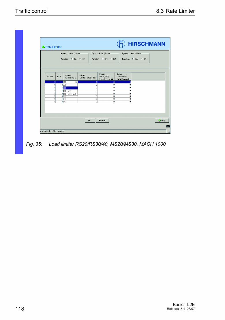
Traffic control 8.3 Rate Limiter
Fig. 35: Load limiter RS20/RS30/40, MS20/MS30, MACH 1000
118Basic - L2E
Release 3.1 06/07
Traffic control 8.4 Prioritization
8.4 Prioritization
8.4.1 Description Prioritization
This function prevents time-critical data traffic such as language/video or real time data from being disrupted by less time-critical data traffic during periods of heavy traffic. By assigning high priority classes for time-critical data and low priority classes for less time-critical data, you ensure optimal data flow for time-critical data traffic.
The Switch supports four priority queues (traffic classes in compliance with IEEE 802.1D-1998). The assignment of received data packets to these clas-ses depends on
D
D the priority of the data packet contained in the VLAN tag.
D the port priority for receiving the data packets that do not contain a tag (see “Configuring ports” on page 69).
Data packets can contain prioritizing/QoS information:
D VLAN priority based on IEEE 802.1Q/ 802.1D-1998 (Layer 2)
8.4.2 Tagging
The VLAN tag is integrated into the MAC data frame for the VLAN and prio-ritization functions in accordance with the IEEE 802.1 Q standard. The VLAN tag consists of 4 Bytes. It is inserted between the source address field and the type field.
With data packets with VLAN tag, the Switch evaluates D the priority information at all times, andD the VLAN information, if VLANs have been set up.
Basic - L2ERelease 3.1 06/07 119
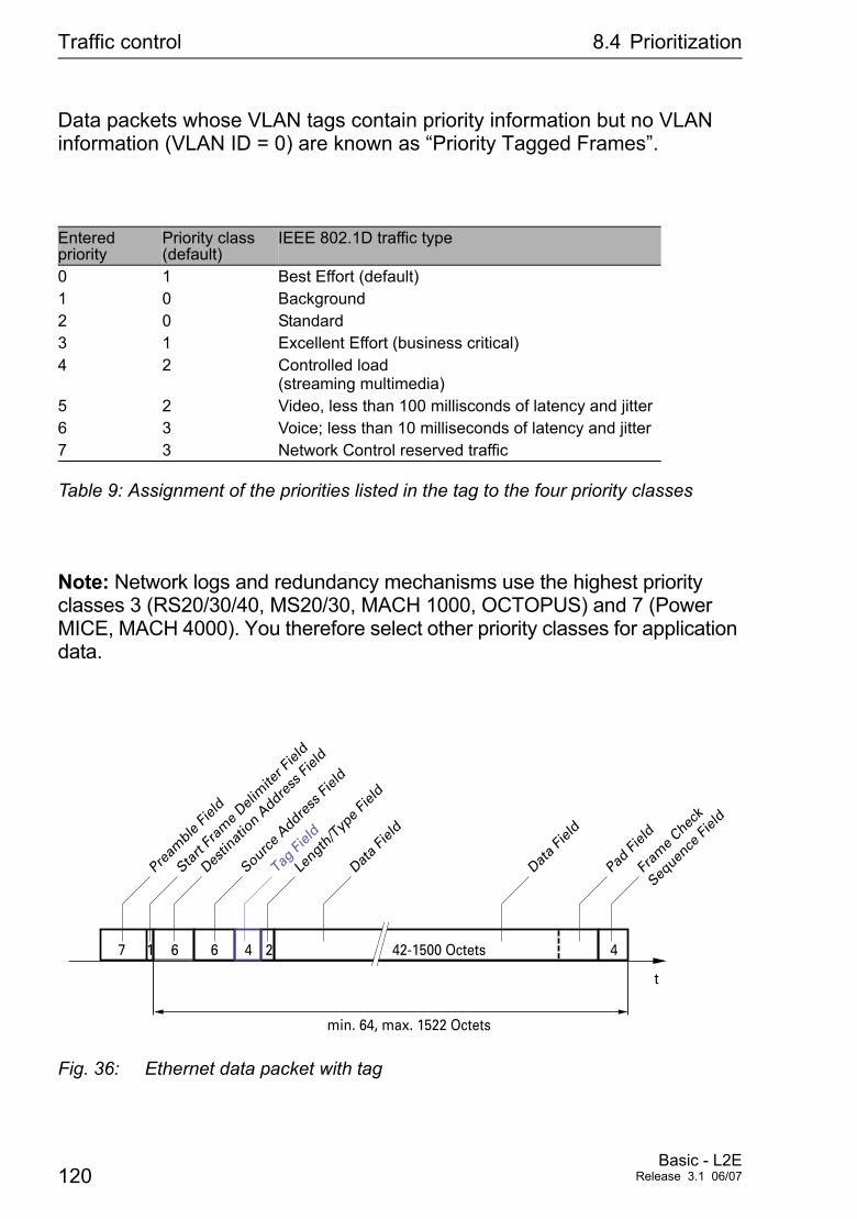
Traffic control 8.4 Prioritization
Data packets whose VLAN tags contain priority information but no VLAN information (VLAN ID = 0) are known as “Priority Tagged Frames”.
Note: Network logs and redundancy mechanisms use the highest priority classes 3 (RS20/30/40, MS20/30, MACH 1000, OCTOPUS) and 7 (Power MICE, MACH 4000). You therefore select other priority classes for application data.
Fig. 36: Ethernet data packet with tag
Entered priority
Priority class (default)
IEEE 802.1D traffic type
0 1 Best Effort (default)1 0 Background2 0 Standard3 1 Excellent Effort (business critical)4 2 Controlled load
(streaming multimedia)5 2 Video, less than 100 millisconds of latency and jitter6 3 Voice; less than 10 milliseconds of latency and jitter7 3 Network Control reserved traffic
Table 9: Assignment of the priorities listed in the tag to the four priority classes
t
min. 64, max. 1522 Octets
Pream
ble Fie
ld
Start
Fram
e Deli
mite
r Fiel
d
Destin
atio
n Addre
ss Fi
eld
Source A
ddress
Field
Tag Fi
eld
Data F
ield
Length
/Typ
e Fiel
d
Data F
ield
Pad Fi
eld
Fram
e Chec
k
Sequen
ce Fi
eld
42-1500 Octets 424667 1
120Basic - L2E
Release 3.1 06/07
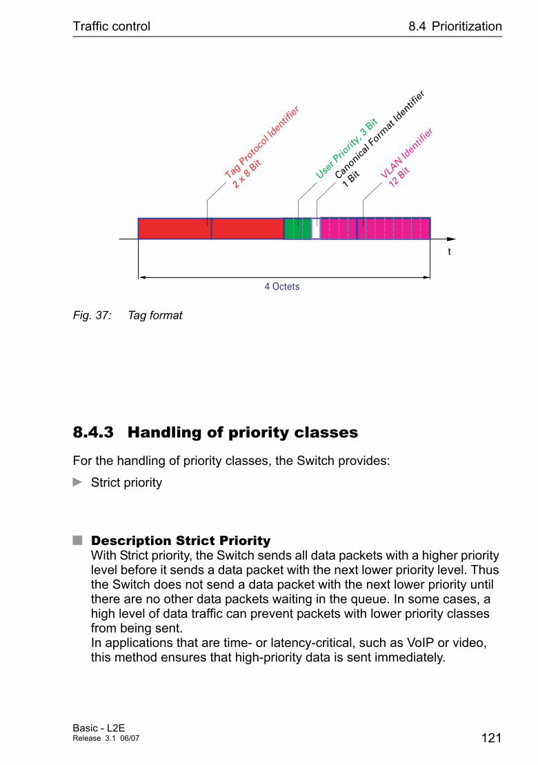
Traffic control 8.4 Prioritization
Fig. 37: Tag format
8.4.3 Handling of priority classes
For the handling of priority classes, the Switch provides:
D Strict priority
U Description Strict PriorityWith Strict priority, the Switch sends all data packets with a higher priority level before it sends a data packet with the next lower priority level. Thus the Switch does not send a data packet with the next lower priority until there are no other data packets waiting in the queue. In some cases, a high level of data traffic can prevent packets with lower priority classes from being sent.In applications that are time- or latency-critical, such as VoIP or video, this method ensures that high-priority data is sent immediately.
t
4 Octets
User P
riorit
y, 3 B
it
Canonica
l Form
at Id
entif
ier
1 Bit VLA
N Iden
tifier
12 B
itTag P
roto
col Id
entif
ier
2 x 8
Bit
Basic - L2ERelease 3.1 06/07 121
Traffic control 8.4 Prioritization
8.4.4 Setting Prioritization
V Select the Basics:Port Configuration.dialog.
V In the “Port Priority” column, you can specify the priority (0-7) with which the Switch sends data packets which it receives without a VLAN tag at this port.
Note: If you have set up VLANs, please observe the “Transparent Mode” under “Configuring VLANs” on page 129.
Setting the priority enable configure interface 1/1
vlan priority 3 ex
Switch to the privileged EXEC mode. Switch to the configuration mode. Switch to the interface configuration mode for Interface 1/1. Assign the port priority 3 to the interface 1/1. Switch to the configuration mode.
Assigning the VLAN priority to the priority classes
enable configure classofservice dot1p-map ping 0 4 classofservice dot1p-map ping 1 4 ex show classofservice dot1p-mapping
Switch to the privileged EXEC mode. Switch to the configuration mode. Assign the priority class 4 to the VLAN priority 0. Assign the priority class 4 to the VLAN priority 1. Switch to the privileged EXEC mode. Display the assignment.
122Basic - L2E
Release 3.1 06/07
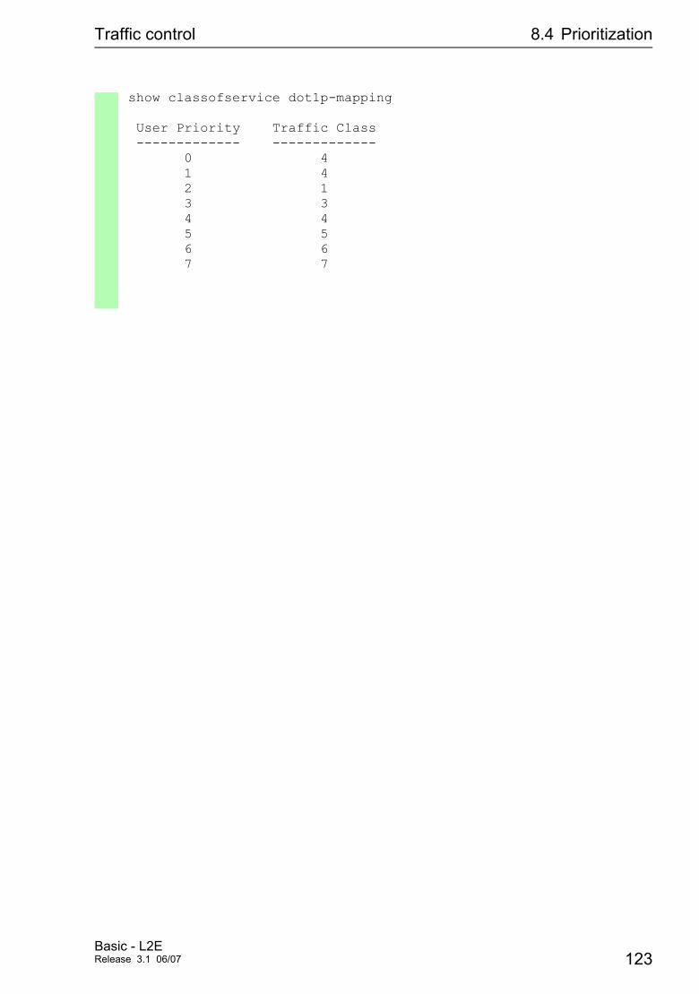
Traffic control 8.4 Prioritization
show classofservice dot1p-mapping
User Priority Traffic Class ------------- ------------- 0 4 1 4 2 1 3 3 4 4 5 5 6 6 7 7
Basic - L2ERelease 3.1 06/07 123
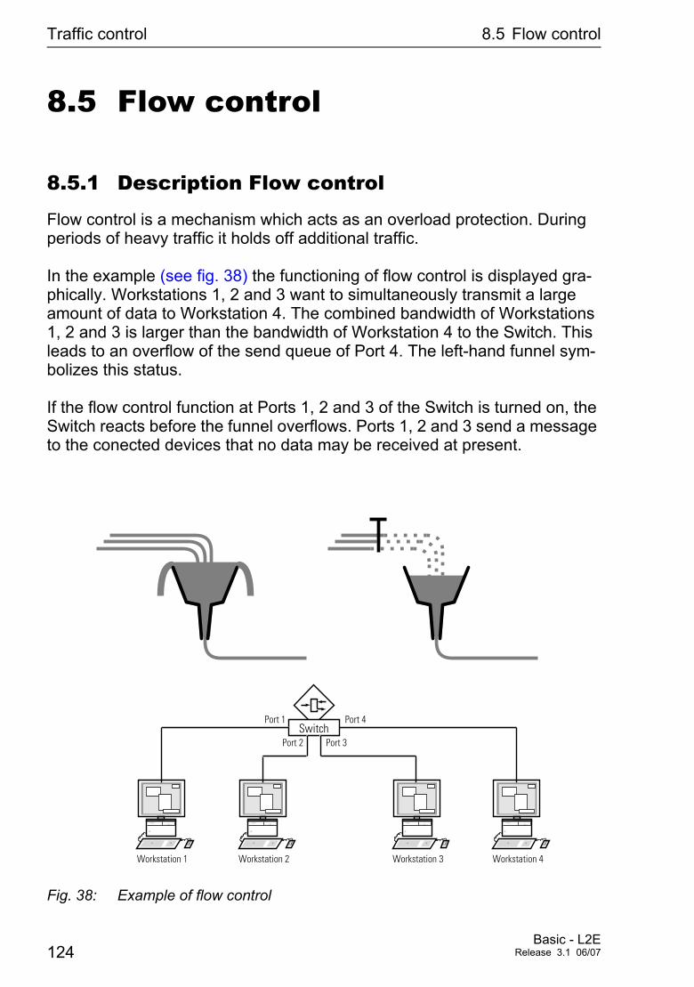
Traffic control 8.5 Flow control
8.5 Flow control
8.5.1 Description Flow control
Flow control is a mechanism which acts as an overload protection. During periods of heavy traffic it holds off additional traffic.
In the example (see fig. 38) the functioning of flow control is displayed gra-phically. Workstations 1, 2 and 3 want to simultaneously transmit a large amount of data to Workstation 4. The combined bandwidth of Workstations 1, 2 and 3 is larger than the bandwidth of Workstation 4 to the Switch. This leads to an overflow of the send queue of Port 4. The left-hand funnel sym-bolizes this status.
If the flow control function at Ports 1, 2 and 3 of the Switch is turned on, the Switch reacts before the funnel overflows. Ports 1, 2 and 3 send a message to the conected devices that no data may be received at present.
Fig. 38: Example of flow control
SwitchPort 3Port 2
Port 1 Port 4
Workstation 1 Workstation 2 Workstation 3 Workstation 4
124Basic - L2E
Release 3.1 06/07
Traffic control 8.5 Flow control
U Flow control with a full duplex linkIn the example (see fig. 38) there is a full duplex link between Work-station 2 and the Switch. Before the send queue of Port 2 overflows, the Switch sends a request to Workstation 2 to include a small break in the sending transmission.
U Flow control with a half duplex linkIn the example (see fig. 38) there is a half duplex link between Work-station 2 and the Switch. Before the send queue of Port 2 overflows, the Switch sends data so that workstation 2 detects a collision and thus interrupts the transmis-sion.
8.5.2 Setting flow control
V Select the Basics:Port Configuration. dialog. In the “Flow Control” column, you mark this port to specify that flow control is active. Activate for this also the global switch “Flow Control” in the Switching:Global dialog.
V Select the Switching:Global dialog. This dialog enables you to – switch off flow control at all ports, or – switch on flow control at all ports which have been selected for flow control in the configuration table.
Basic - L2ERelease 3.1 06/07 125
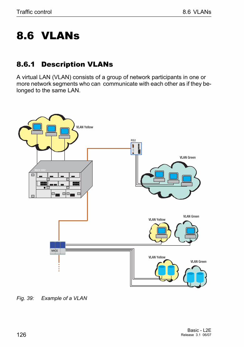
Traffic control 8.6 VLANs
8.6 VLANs
8.6.1 Description VLANs
A virtual LAN (VLAN) consists of a group of network participants in one or more network segments who can communicate with each other as if they be-longed to the same LAN.
Fig. 39: Example of a VLAN
MACH 3002
RS2
MICE
VLAN Yellow
VLAN Green
VLAN Green
VLAN Green
VLAN Yellow
VLAN Yellow
126Basic - L2E
Release 3.1 06/07
Traffic control 8.6 VLANs
VLANs are based on logical (instead of physical) links and are flexible elements in the network design. The biggest advantage of VLANs is the possibility of forming user groups based on the participant function and not on their physical location or medium.Since broad/multicast data packets are transmitted exclusively within a virtual LAN, the remaining data network is unaffected.
The VLAN function is defined in the IEEE 802.1Q standard. The maximum number of VLANs is limited by the structure of the VLAN tag (see fig. 37) to 4094.
Key words often used in association with VLANs are:
U Ingress RuleThe ingress rules stipulate how incoming data is to be handled by the Switch.
U Egress RuleThe egress rules stipulate how outgoing data is to be handled by the Switch.
U VLAN identifierThe assignment to a VLAN is effected via a VLAN ID. Every VLAN exi-sting in a network is identified by an ID. This ID must be unique, i.e. every ID may only be assigned once in the network.
U Port VLAN identifier (PVID)The management assigns a VLAN ID for every port. It is known, there-fore, as the port VLAN ID. The Switch adds a tag to every data packet received with no tag. This tag contains a valid VLAN ID. When a data packet is received with a priority tag the Switch adds the port VLAN ID.
Basic - L2ERelease 3.1 06/07 127

Traffic control 8.6 VLANs
U Member setThe member set is list of ports belonging to a VLAN. Every VLAN has a member set.
U Untagged setThe untagged set is a list of the ports of a VLAN which send data packets without a tag. Every VLAN has an untagged set.
128Basic - L2E
Release 3.1 06/07
Traffic control 8.6 VLANs
8.6.2 Configuring VLANs
V Select the Switching:VLAN. Dialog.
Under VLAN you will find all tables and attributes to configure and mo-nitor the VLAN functions complying with IEEE 802.1Q standard.
V Select the dialog Switching:VLAN:Global.V Activate “VLAN Transparent Mode” to transmit priority-tagged
packets that are not a member of a VLAN, i.e. have a VLAN-ID of “0”. In this mode the VLAN-ID “0” is retained in the packet, regardless of the setting of the port VLAN ID in the “VLAN Port” dialog.
Note: For RS20/RS30/RS40, MS20/MS30, MACH 1000 and OCTOPUS In “transparent mode”, the devices ignore the set port VLAN-ID. Set the VLAN membership of the ports of VLAN 1 to member or untagged.
Note:
Note: When configuring the VLAN, ensure that the port to which your management station is connected, can still send the data of the mana-gement station after saving the VLAN configuration. Assigning the port to the VLAN with ID 1 always ensures that the management station data can be sent.
After changing entries:
Set The agent saves the new entry. The modification will take effect immediately.
Reload Displays the updated configuration.
Note: Save the VLAN configuration to non-volatile memory (see fig. 45).
Note: The 256 available VLANs can use any VLAN ID in the range 1 to 4042.
Basic - L2ERelease 3.1 06/07 129
Traffic control 8.6 VLANs
Note: In a HIPER-Ring with VLANs you should only operate devices with the software that supports this function, namely:
D RS2 xx/xx (from Vers. 7.00),D RS2-16M,D RS 20, RS 30, RS 40D MICE (from Rel. 3.0) orD Power MICED MS 20, MS 30D MACH 1000D MACH 3000 (from Rel. 3.3)D MACH 4000D OCTOPUS
Note: In the HIPER-Ring configuration, select for the ring ports – VLAN ID 1 and “Ingress Filtering” disabled in the port table and – VLAN affiliation U in the static table.
Note: In the Ring/Network Coupling configuration, select for the cou-pling and partner coupling ports – VLAN ID 1 and “Ingress Filtering” disabled in the port table and – VLAN affiliation U in the static table.
130Basic - L2E
Release 3.1 06/07
Traffic control 8.6 VLANs
8.6.3 Setting up VLANs
8.6.4 Displaying the VLAN configuration
V Select the Switching:VLAN:Static dialog.
To set up VLANs, you first specify the desired VLANs in the VLAN static table:
V After clicking on “Create”, you enter the appropriate VLAN ID. A new line appears in the table.
V Enter the name of your choice for this VLAN.
V Define the affiliation of the ports you require. - not a member of the VLAN. M a member of the VLAN - packet is transmitted with tag . F not a member of the VLAN U a member of the VLAN - packet is transmitted without tag.
V After setting up VLANs, you specify the rules for received data in the VLAN Port table (port):
D Port VLAN ID specifies to which VLAN a received untagged data packet is assi-gned.
D Acceptable Frame Types detemines if data packets can also be received untagged.
D Ingress Filtering specifies whether the received tags are evaluated.
V Select the Switching:VLAN:Current dialog. The Current table displays all locally configured VLANs.
Basic - L2ERelease 3.1 06/07 131

Traffic control 8.6 VLANs
8.6.5 Deleting the VLAN settings
V Select the Switching:VLAN:Global dialog. The “Delete” button in the VLAN global dialog allows you to restore all the default VLAN settings of the device (state on delivery).
V Select the Switching:VLAN:Static dialog. The “Delete” button in the VLAN static dialog allows you to delete a selected row of the table.
132Basic - L2E
Release 3.1 06/07
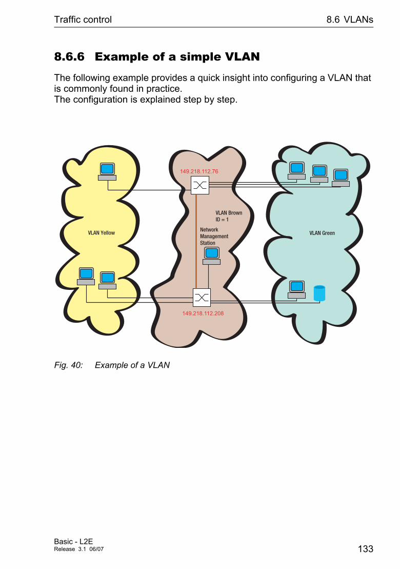
Traffic control 8.6 VLANs
8.6.6 Example of a simple VLAN
The following example provides a quick insight into configuring a VLAN that is commonly found in practice. The configuration is explained step by step.
Fig. 40: Example of a VLAN
149.218.112.208
149.218.112.76
VLAN Yellow VLAN Green
VLAN Brown ID = 1
Network Management Station
Basic - L2ERelease 3.1 06/07 133
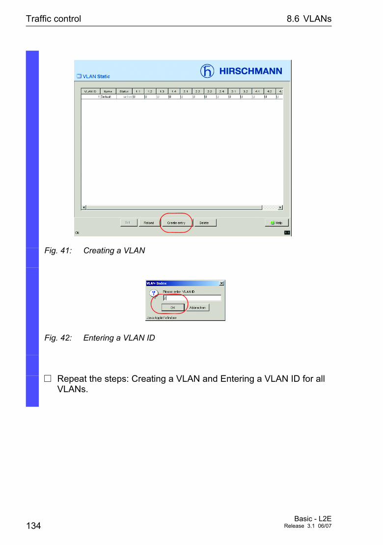
Traffic control 8.6 VLANs
Fig. 41: Creating a VLAN
Fig. 42: Entering a VLAN ID
V Repeat the steps: Creating a VLAN and Entering a VLAN ID for all VLANs.
134Basic - L2E
Release 3.1 06/07
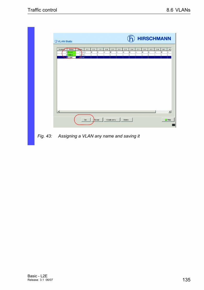
Traffic control 8.6 VLANs
Fig. 43: Assigning a VLAN any name and saving it
Basic - L2ERelease 3.1 06/07 135
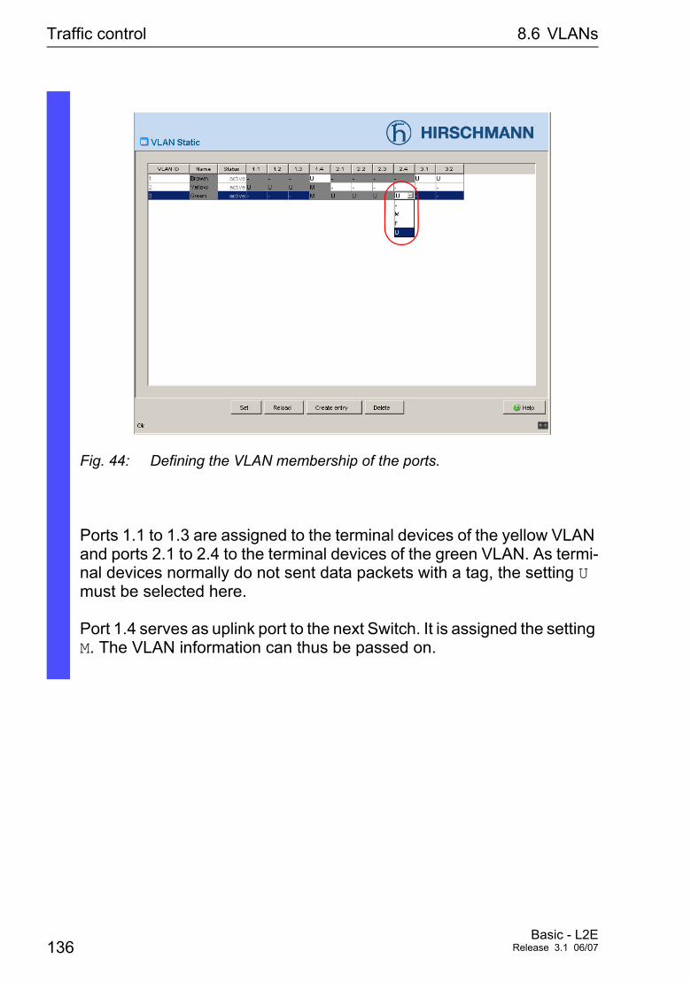
Traffic control 8.6 VLANs
Fig. 44: Defining the VLAN membership of the ports.
Ports 1.1 to 1.3 are assigned to the terminal devices of the yellow VLAN and ports 2.1 to 2.4 to the terminal devices of the green VLAN. As termi-nal devices normally do not sent data packets with a tag, the setting U must be selected here.
Port 1.4 serves as uplink port to the next Switch. It is assigned the setting M. The VLAN information can thus be passed on.
136Basic - L2E
Release 3.1 06/07
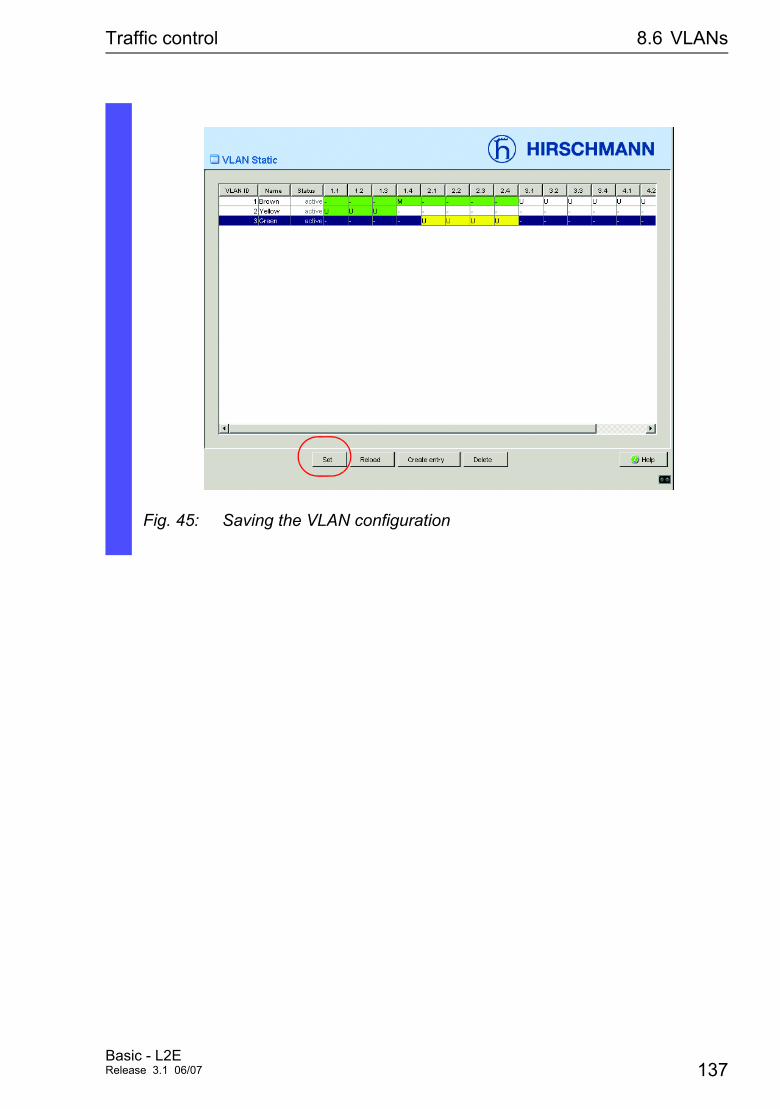
Traffic control 8.6 VLANs
Fig. 45: Saving the VLAN configuration
Basic - L2ERelease 3.1 06/07 137
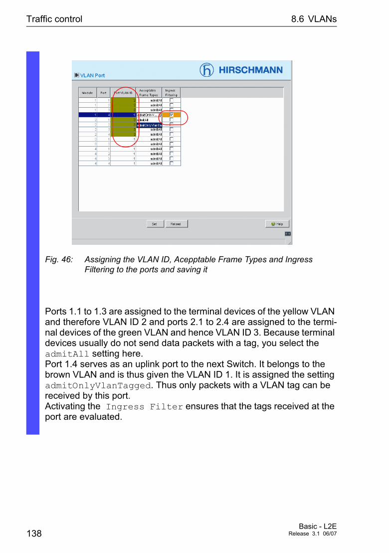
Traffic control 8.6 VLANs
Fig. 46: Assigning the VLAN ID, Acepptable Frame Types and Ingress Filtering to the ports and saving it
Ports 1.1 to 1.3 are assigned to the terminal devices of the yellow VLAN and therefore VLAN ID 2 and ports 2.1 to 2.4 are assigned to the termi-nal devices of the green VLAN and hence VLAN ID 3. Because terminal devices usually do not send data packets with a tag, you select the admitAll setting here.Port 1.4 serves as an uplink port to the next Switch. It belongs to the brown VLAN and is thus given the VLAN ID 1. It is assigned the setting admitOnlyVlanTagged. Thus only packets with a VLAN tag can be received by this port. Activating the Ingress Filter ensures that the tags received at the port are evaluated.
138Basic - L2E
Release 3.1 06/07
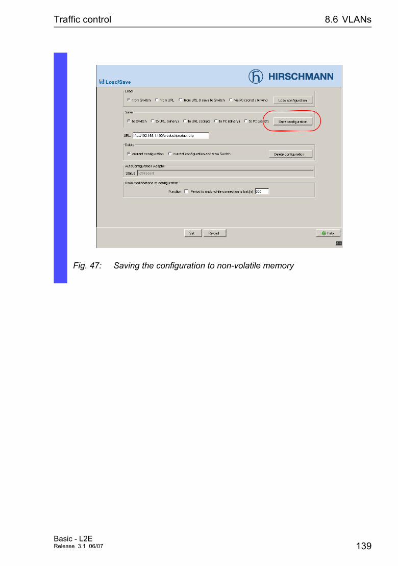
Traffic control 8.6 VLANs
Fig. 47: Saving the configuration to non-volatile memory
Basic - L2ERelease 3.1 06/07 139

Traffic control 8.6 VLANs
140Basic - L2E
Release 3.1 06/07

Operation Diagnostics
9 Operation Diagnostics
The Switch provides you with the following diagnostic tools for the function diagnosis:
D Sending trapsD Monitoring Device StatusD Out-of-band signaling via signal contactD Port status indicationD Event counter on port levelD SFP status indicationD Topology discoveryD ReportsD Monitoring the traffic of a port (Portmirroring)
Basic - L2ERelease 3.1 06/07 141
Operation Diagnostics 9.1 Sending traps
9.1 Sending traps
If unusual events occur during normal operation of the Switch, they are reported immediately to the management station. This is done by means of so-called traps - alarm messages - that bypass the polling procedure (“Polling” means querying the data stations at regular intervals). Traps make it possible to react quickly to critical situations.
Examples of such events are:
D a hardware resetD changing the basic device configurationD segmentation of a portD ...
Traps can be sent to various hosts to increase the transmission reliability for the messages. A trap message consists of a packet that is not acknowl-edged. The Switch sends traps to those hosts that are entered in the trap destination table. The trap destination table can be configured with the management sta-tion via SNMP.
142Basic - L2E
Release 3.1 06/07
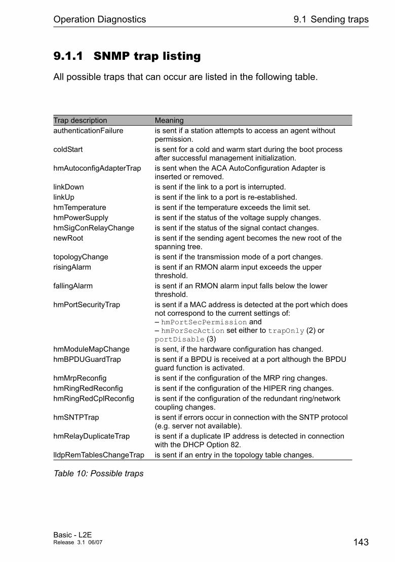
Operation Diagnostics 9.1 Sending traps
9.1.1 SNMP trap listing
All possible traps that can occur are listed in the following table.
Trap description MeaningauthenticationFailure is sent if a station attempts to access an agent without
permission.coldStart is sent for a cold and warm start during the boot process
after successful management initialization.hmAutoconfigAdapterTrap is sent when the ACA AutoConfiguration Adapter is
inserted or removed.linkDown is sent if the link to a port is interrupted.linkUp is sent if the link to a port is re-established.hmTemperature is sent if the temperature exceeds the limit set.hmPowerSupply is sent if the status of the voltage supply changes.hmSigConRelayChange is sent if the status of the signal contact changes.newRoot is sent if the sending agent becomes the new root of the
spanning tree.topologyChange is sent if the transmission mode of a port changes.risingAlarm is sent if an RMON alarm input exceeds the upper
threshold.fallingAlarm is sent if an RMON alarm input falls below the lower
threshold.hmPortSecurityTrap is sent if a MAC address is detected at the port which does
not correspond to the current settings of: – hmPortSecPermission and – hmPorSecAction set either to trapOnly (2) or portDisable (3)
hmModuleMapChange is sent, if the hardware configuration has changed.hmBPDUGuardTrap is sent if a BPDU is received at a port although the BPDU
guard function is activated.hmMrpReconfig is sent if the configuration of the MRP ring changes.hmRingRedReconfig is sent if the configuration of the HIPER ring changes.hmRingRedCplReconfig is sent if the configuration of the redundant ring/network
coupling changes.hmSNTPTrap is sent if errors occur in connection with the SNTP protocol
(e.g. server not available).hmRelayDuplicateTrap is sent if a duplicate IP address is detected in connection
with the DHCP Option 82.lldpRemTablesChangeTrap is sent if an entry in the topology table changes.
Table 10: Possible traps
Basic - L2ERelease 3.1 06/07 143
Operation Diagnostics 9.1 Sending traps
9.1.2 SNMP traps when booting
The ColdStart trap is sent during every boot procedure.
9.1.3 Configuring traps
V Select the Diagnostics:Alarms (Traps) dialog.
This dialog allows you to specify which events trigger an alarm (trap) and to whom these alarms should be sent.
V In the “IP Address” column, enter the IP address of a network management station to which the traps should be sent.
V In the “Active” column, you mark the entries which should be taken into account when traps are being sent.
V In the frame “Selection” select these trap catagories from which you want to send traps
Note: Access this dialog with read-write password.
144Basic - L2E
Release 3.1 06/07
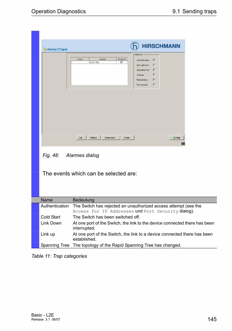
Operation Diagnostics 9.1 Sending traps
Fig. 48: Alarmes dialog
The events which can be selected are:
Name BedeutungAuthentication The Switch has rejected an unauthorized access attempt (see the
Access for IP Addresses und Port Security dialog).Cold Start The Switch has been switched off.Link Down At one port of the Switch, the link to the device connected there has been
interrupted.Link up At one port of the Switch, the link to a device connected there has been
established.Spanning Tree The topology of the Rapid Spanning Tree has changed.
Table 11: Trap categories
Basic - L2ERelease 3.1 06/07 145
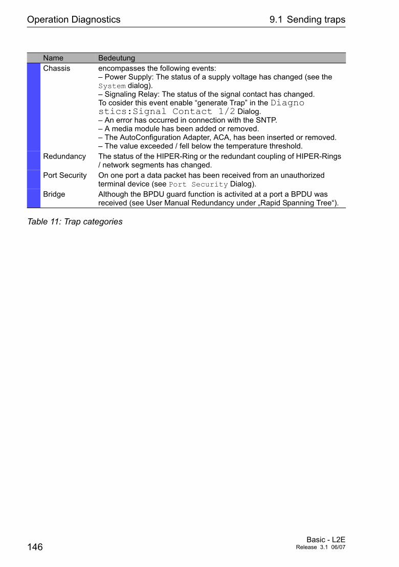
Operation Diagnostics 9.1 Sending traps
Chassis encompasses the following events: – Power Supply: The status of a supply voltage has changed (see the System dialog). – Signaling Relay: The status of the signal contact has changed. To cosider this event enable “generate Trap” in the Diagno stics:Signal Contact 1/2 Dialog. – An error has occurred in connection with the SNTP. – A media module has been added or removed. – The AutoConfiguration Adapter, ACA, has been inserted or removed. – The value exceeded / fell below the temperature threshold.
Redundancy The status of the HIPER-Ring or the redundant coupling of HIPER-Rings / network segments has changed.
Port Security On one port a data packet has been received from an unauthorized terminal device (see Port Security Dialog).
Bridge Although the BPDU guard function is activited at a port a BPDU was received (see User Manual Redundancy under „Rapid Spanning Tree“).
Name Bedeutung
Table 11: Trap categories
146Basic - L2E
Release 3.1 06/07
Operation Diagnostics 9.2 Monitoring Device Status
9.2 Monitoring Device Status
The device status provides an overview of the overall condition of the Switch. Many process visualization systems record the device status for a device in order to present its condition in graphic form. The Switch enables you to
D signal the device status out-of-band via a signal contact (see “Monitoring the Device Status with a signal contact” on page 153).
D signal the device status by sending a trap when the device status changes.
D detect the device status in the Web-based interface on the system side.
D query the device status in the Command Line Interface.
The device status of the Switch includes:
D Incorrect supply voltage, the failure of at least one of the two supply voltages or a permanent fault in the Switch (internal supply voltage).
D The temperature threshold has been exceeded or has not been reached.
D Removing a module (at modulare devices).
D Removing the ACA.
D Failure of a fan (MACH 4000).
D The defective link status of at least one port. With the Switch, the indica-tion of link status can be masked by the management for each port (see “Displaying connection error messages” on page 70). Link status is not monitored in the delivery condition.
D HIPER-Ring event: the loss of redundancy guarantee (in Redundancy Manager mode). Ring redundancy is not monitored in the delivery condition.
D Redundant Ring/Netcoupling event: the loss of redundancy guarantee. Ring redundancy is not monitored in the delivery condition. In Stand-by mode the Switch reports additionally the following conditions: – the faulty link status of the control line – partner device is in stand-by mode
Basic - L2ERelease 3.1 06/07 147
Operation Diagnostics 9.2 Monitoring Device Status
It depends on the management setting which events cause a contact to switch.
Note: With non-redundant supply of the mains voltage, the Switch reports a power failure. You can prevent this message by applying the supply voltage over the two inputs or by switching off the monitoring (see “Monitoring correct operation via the signal contact” on page 152).
V Select the Diagnostics:Device Status.V Select in the frame “Monitoring correct operation” the events which
you want to have monitored.V For temperature monitoring set in the Basics:System dialog at the
end of the system data the temperature thresholds..
Configure Device Status
enable configure device-status monitor all en able device-status trap enable
Switch to the privileged EXEC mode. Switch to the configuration mode. Includes all the possible events in the device sta-tus determination. Enables a trap to be sent if the device status changes.
Display Device Status
exit show device-status
Switch to the privileged EXEC mode. Displays the device status and the setting for the device status determination.
148Basic - L2E
Release 3.1 06/07
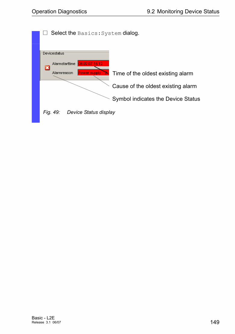
Operation Diagnostics 9.2 Monitoring Device Status
V Select the Basics:System dialog.
Fig. 49: Device Status display
Time of the oldest existing alarm
Cause of the oldest existing alarm
Symbol indicates the Device Status
Basic - L2ERelease 3.1 06/07 149
Operation Diagnostics 9.3 Out-of-band signaling
9.3 Out-of-band signaling
The signal contacts are for
D controlling external devices by manually setting the signal contacts.D monitoring proper functioning of the Switch which makes it possible to
perform remote diagnostics.
A break in contact is reported via the potential-free signal contact (relay contact, closed circuit):
D Faulty power supply: the failure of the supply voltage 1/2, a continuous malfunction in the Switch (internal supply voltage).
D Values that exceed or fall below the set temperature threshold.
D Removing a module.
D Removing the ACA.
D The defective link status of at least one port. With the Switch, the indica-tion of link status can be masked by the management for each port (see “Displaying connection error messages” on page 70). Link status is not monitored in the delivery condition.
D HIPER-Ring event: the loss of redundancy guarantee (in Redundancy Manager mode). Ring redundancy is not monitored in the delivery condition.
D Redundant Ring/Netcoupling event: the loss of redundancy guarantee. Ring redundancy is not monitored in the delivery condition. In Stand-by mode the Switch reports additionally the following conditions: – the faulty link status of the control line – partner device is in stand-by mode
It depends on the management setting which events cause a contact to switch.
Note: With non-redundant supply of the mains voltage, the Switch reports a power failure. You can prevent this message by applying the supply voltage over the two inputs or by switching off the monitoring (see “Monitoring correct operation via the signal contact” on page 152).
150Basic - L2E
Release 3.1 06/07
Operation Diagnostics 9.3 Out-of-band signaling
9.3.1 Manual setting the signal contact
This mode gives you the option of remote switching each signal individually.
Application options:
D Simulation of an error during SPS error monitoring.
D Remote control of a device via SNMP, such as switching on a camera..
V Select the Diagnostics:Signal Contact 1/2 dialog.
V Select “Manual setting” in the “Mode Signal Contact” frame, to switch the contact manually.
V Select “Opened” in the “Manual setting” frame to open the contact.
V Select “Closed” in the “Manual setting” frame to close the contact.
Configure signal contact
enable configure signal-contact 1 mode manual signal-contact 1 state open signal-contact 1 state closed
Switch to the privileged EXEC mode. Switch to the configuration mode. Selects the manual setting mode for signal contact 1.Opens signal contact 1.Closes signal contact 1.
Basic - L2ERelease 3.1 06/07 151
Operation Diagnostics 9.3 Out-of-band signaling
9.3.2 Monitoring correct operation via the signal contact
U Configuring the monitoring correct operation
U Signal contact displayYou can view the signal contact status in three ways:D using the LED display,D using the web-based interface,D executing a query in the command line interface.
V Select the Diagnostics:Signal Contact dialog.V Select “Monitoring correct operation” in the frame “Mode Signal con-
tact”, to use the contact for function monitoring.V Select in the frame “Monitoring correct operation” the events which
you want to have monitored.V For temperature monitoring set in the Basics:System dialog at the
end of the system data the temperature thresholds..
Configuing the monitoring correct operation
enable configure signal-contact 1 monitor all signal-contact 1 trap enable
Switch to the privileged EXEC mode. Switch to the configuration mode. Includes all the possible events in the function monitoring. Enables a trap to be sent if the status of the function monitoring changes.
152Basic - L2E
Release 3.1 06/07
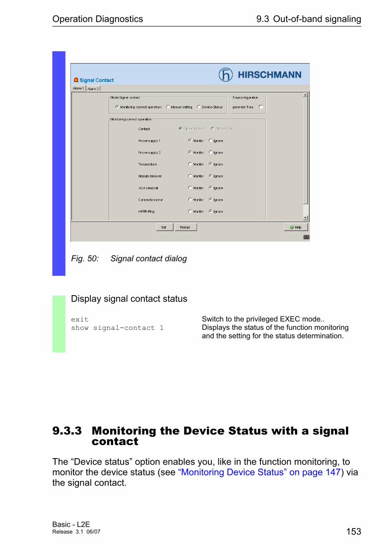
Operation Diagnostics 9.3 Out-of-band signaling
9.3.3 Monitoring the Device Status with a signal contact
The “Device status” option enables you, like in the function monitoring, to monitor the device status (see “Monitoring Device Status” on page 147) via the signal contact.
Fig. 50: Signal contact dialog
Display signal contact status
exit show signal-contact 1
Switch to the privileged EXEC mode.. Displays the status of the function monitoring and the setting for the status determination.
Basic - L2ERelease 3.1 06/07 153
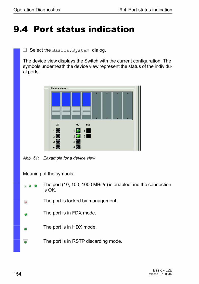
Operation Diagnostics 9.4 Port status indication
9.4 Port status indication
V Select the Basics:System dialog.
The device view displays the Switch with the current configuration. The symbols underneath the device view represent the status of the individu-al ports.
Abb. 51: Eaxample for a device view
Meaning of the symbols:
The port (10, 100, 1000 MBit/s) is enabled and the connection is OK.
The port is locked by management.
The port is in FDX mode.
The port is in HDX mode.
The port is in RSTP discarding mode.
154Basic - L2E
Release 3.1 06/07

Operation Diagnostics 9.4 Port status indication
The port is in autonegotiation mode.
Basic - L2ERelease 3.1 06/07 155
Operation Diagnostics 9.5 Event counter on port level
9.5 Event counter on port level
The port statistics table allows experienced network administrators to identify possible problems occuring in the network.This table shows you the contents of various event counters. In the menü item restart with "Restart Switch", "Hot restart" or "Reset port counters" you can reset all event counters to zero. The counters add up the events transmitted and the events received.
Counter Possible ProblemsReceived Fragments – The controller of the connected device is faulty.
– Electromagnetic interference is injected into transfer medium.CRC error – The controller of the connected device is faulty.
– Electromagnetic interference is injected into transfer medium - there is a faulty component in the network.
Collisions – The controller of the connected device is faulty. – The network expansion is too big or the line is too long. – A packet has collided with an intererence signal.
Table 12: Examples indicating possible problems
V Select the Diagnostics:Ports:Statistics dialog.
V For reseting port counters select “Reset port counters” in the Ba sics:Restart dialog.
156Basic - L2E
Release 3.1 06/07
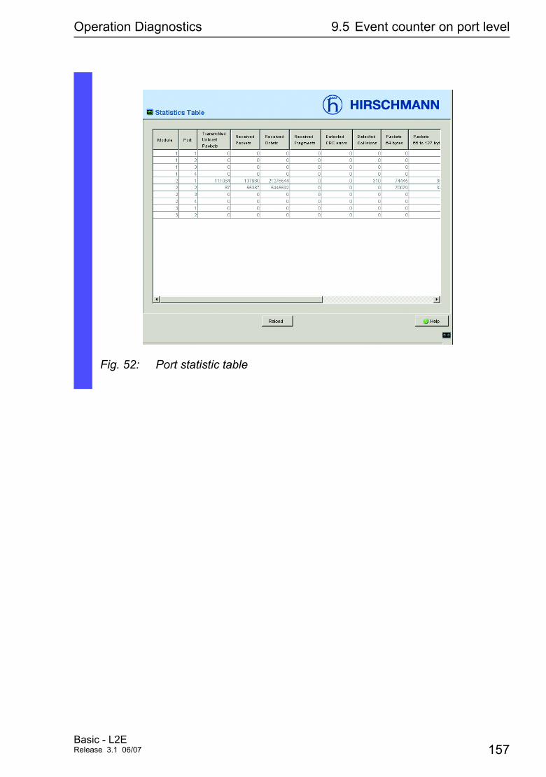
Operation Diagnostics 9.5 Event counter on port level
Fig. 52: Port statistic table
Basic - L2ERelease 3.1 06/07 157
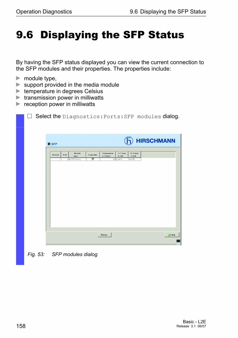
Operation Diagnostics 9.6 Displaying the SFP Status
9.6 Displaying the SFP Status
By having the SFP status displayed you can view the current connection to the SFP modules and their properties. The properties include:
D module type,D support provided in the media module D temperature in degrees Celsius D transmission power in milliwatts D reception power in milliwatts
V Select the Diagnostics:Ports:SFP modules dialog.
Fig. 53: SFP modules dialog
158Basic - L2E
Release 3.1 06/07
Operation Diagnostics 9.7 Topology discovery
9.7 Topology discovery
9.7.1 Description Topology discovery
IEEE 802.1AB describes the Link Layer Discovery Protocol (LLDP). LLDP allows users to automatically detect the topology of their LANs.
A device with active LLDP
D sends its own connection and management information to neighboring devices of the shared LAN, in as far as they have also LLDP activated.
D receives connection and management information from neighboring de-vices of the shared LAN, in as far as they have also LLDP activated.
D sets up a management information scheme and object definitions for saving connection information of neighboring devices that have LLDP activated.
The connection information contains as its most significant element the precise and unique ID of a connection endpoint: MSAP (MAC Service Access Point). This is composed of the MAC address of the device and a port ID that is unique to this device. Contents of the connection and management information:
D Chassis ID (its MAC address)D Port ID (its port MAC address)D Description of the portD System nameD System descriptionD Supported “system capabilities” (e.g. router = 14 or switch = 4)D Currently activated “system capabilities”D Interface ID of the management addressD VLAN-ID of the portD Status of autonegotiation on the portD Medium, half/full duplex setting and transmission speed setting of the portD Information about the redundancy protocol (STP, RSTP, HIPER-Ring,
ring coupling, dual homing) which is activated at this port.D VLAN information concerning the port (VLAN ID and VLAN name).
Basic - L2ERelease 3.1 06/07 159
Operation Diagnostics 9.7 Topology discovery
This information can be called up from a network management station. With this information, the network management station is able to display the topo-logy of the network.
LLDP uses an IEEE-MAC address for exchanging information. This address is normally not routed by switches. This is why switches without LLDP support drop the LLDP packets. Consequently, a non-LLDP-capable device between two LLDP-capable devices prevents the exchange of LLDP infor-mation. To avoid this, Hirschmann Switch send additional LLDP packets to the Hirschmann Multicast-MAC address 01:80:63:2F:FF:0B. Hirschmann Switch with the LLDP function are thus also able to exchange LLDP informa-tion with each other via devices which themselves are not LLDP-capable.
The Management Information Base (MIB) of an LLDP capable Hirschmann Switch holds out the LLDP information in the lldp-MIB and in the private hmlldp-MIB.
160Basic - L2E
Release 3.1 06/07
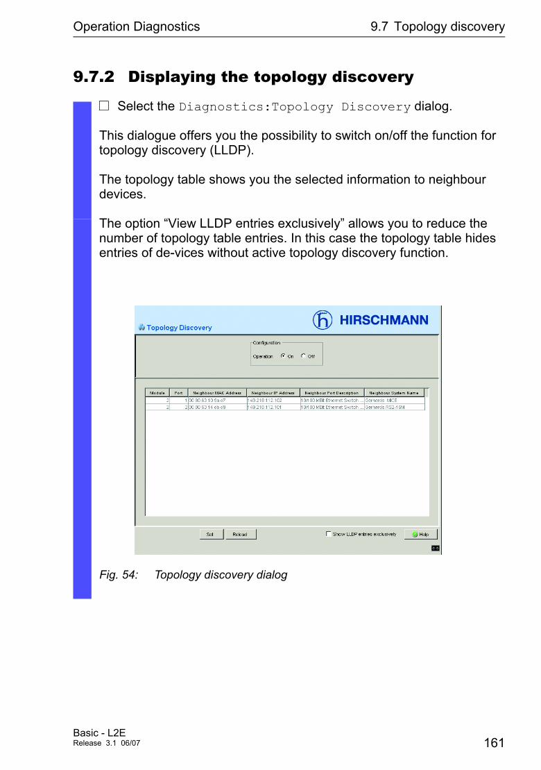
Operation Diagnostics 9.7 Topology discovery
9.7.2 Displaying the topology discovery
V Select the Diagnostics:Topology Discovery dialog.
This dialogue offers you the possibility to switch on/off the function for topology discovery (LLDP).
The topology table shows you the selected information to neighbour devices.
The option “View LLDP entries exclusively” allows you to reduce the number of topology table entries. In this case the topology table hides entries of de-vices without active topology discovery function.
Fig. 54: Topology discovery dialog
Basic - L2ERelease 3.1 06/07 161
Operation Diagnostics 9.7 Topology discovery
If several devices are connected to a port, for example via a hub, the table shows one line for each connected device.
IfD devices with active topology discovery function andD devices without active topology discovery functionare connected to a port, the topology table hides the devices without ac-tive topology discovery.
IfD only devices without active topology discoveryare connected to a port, the table will contain one line for this port sym-boli-cally for all devices. The line contains the number of connected de-vices.MAC addresses of devices that the topology table hides for the sake of clarity, are located in the Address Table (FDB, see “Entering static address entries” on page 108).
162Basic - L2E
Release 3.1 06/07
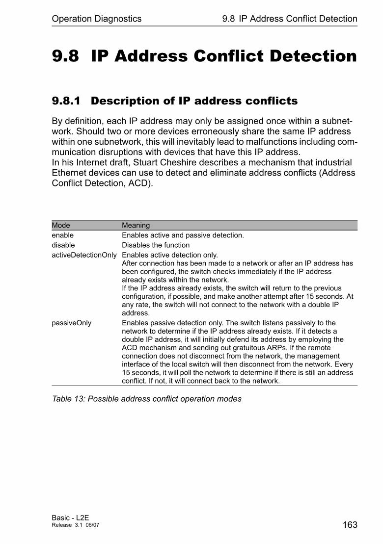
Operation Diagnostics 9.8 IP Address Conflict Detection
9.8 IP Address Conflict Detection
9.8.1 Description of IP address conflicts
By definition, each IP address may only be assigned once within a subnet-work. Should two or more devices erroneously share the same IP address within one subnetwork, this will inevitably lead to malfunctions including com-munication disruptions with devices that have this IP address. In his Internet draft, Stuart Cheshire describes a mechanism that industrial Ethernet devices can use to detect and eliminate address conflicts (Address Conflict Detection, ACD).
Mode Meaningenable Enables active and passive detection.disable Disables the functionactiveDetectionOnly Enables active detection only.
After connection has been made to a network or after an IP address has been configured, the switch checks immediately if the IP address already exists within the network. If the IP address already exists, the switch will return to the previous configuration, if possible, and make another attempt after 15 seconds. At any rate, the switch will not connect to the network with a double IP address.
passiveOnly Enables passive detection only. The switch listens passively to the network to determine if the IP address already exists. If it detects a double IP address, it will initially defend its address by employing the ACD mechanism and sending out gratuitous ARPs. If the remote connection does not disconnect from the network, the management interface of the local switch will then disconnect from the network. Every 15 seconds, it will poll the network to determine if there is still an address conflict. If not, it will connect back to the network.
Table 13: Possible address conflict operation modes
Basic - L2ERelease 3.1 06/07 163
Operation Diagnostics 9.8 IP Address Conflict Detection
9.8.2 Configuring ACD
9.8.3 Displaying ACD
V Select the dialog Diagnostics:IP Address Conflict Detection.
V With “Status” you can enable or disable IP address conflict detection or select the operating mode (see Tab. 13 on page 163).
V Select the dialog Diagnostics:IP Address Conflict Detection.
V This dialog logs the IP address conflicts which the Switch detects, if it detects a conflict with its IP address. For each conflict, the Switch: – logs the time, – the conflicting IP address, – the MAC address of the device with which the IP address conflicted. The Switch writes one line to the log for each IP address that represents the last conflict that occurred.
V You can delete this table by restarting the Switch.
164Basic - L2E
Release 3.1 06/07
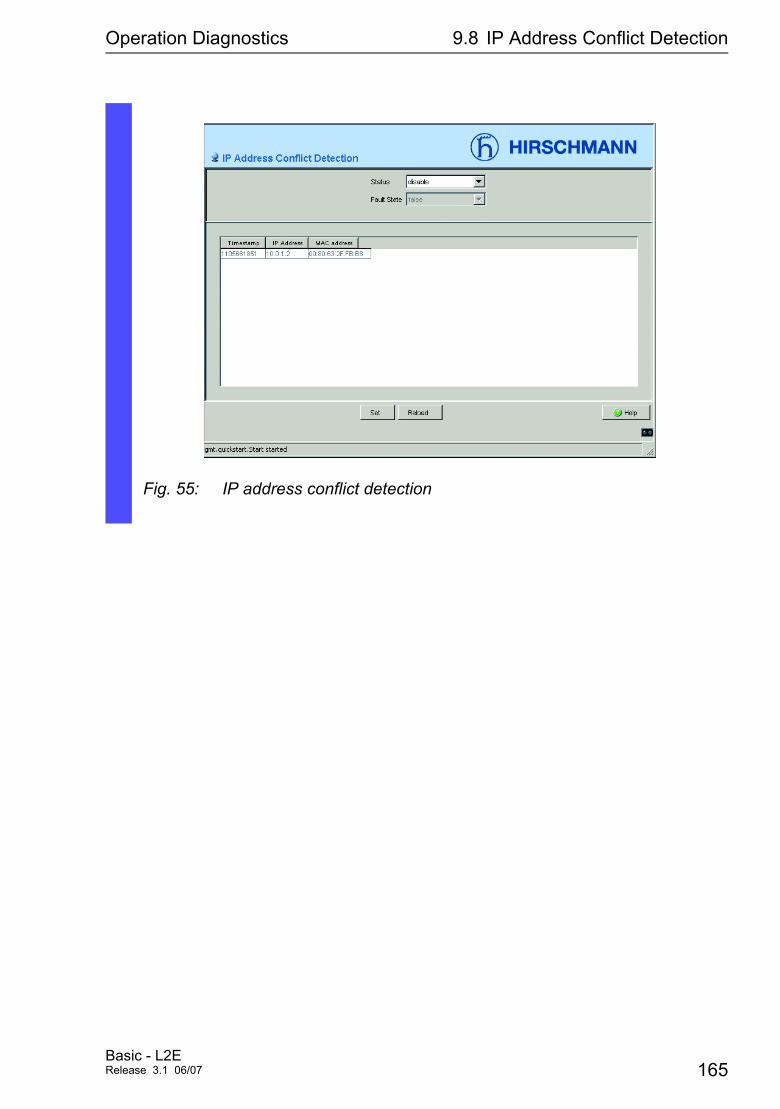
Operation Diagnostics 9.8 IP Address Conflict Detection
Fig. 55: IP address conflict detection
Basic - L2ERelease 3.1 06/07 165
Operation Diagnostics 9.9 Reports
9.9 Reports
For diagnosis purposes, the Switch allows you to use the following reports:
D Log Filei The Log File is an HTML file in which the Switch records all important device internal events.
D System Information The system information in an HTML file containing all system relevant data.
D System Information The security data sheet IAONA is a data sheet in the XML format that has been standardized by IAONA (Industrial Automation Open Networking Alliance). Among other data, it contains security-related information on the accessible ports and the associated protocols.
D Diagnostic table The diagnostic table lists the alarms that were generated (traps).
These reports are available for diagnosis purposes. In service situations they report necessary information to the technician.
V Select the Diagnostics:Report dialog.
V Click “Log File” to open the HTML file in a new browser window.
V Click “System information” to open the HTML file in a new browser window.
166Basic - L2E
Release 3.1 06/07
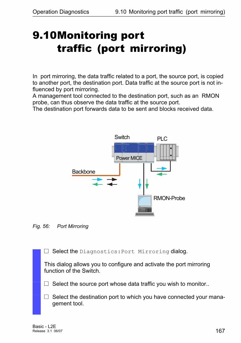
Operation Diagnostics 9.10 Monitoring port traffic (port mirroring)
9.10Monitoring port traffic (port mirroring)
In port mirroring, the data traffic related to a port, the source port, is copied to another port, the destination port. Data traffic at the source port is not in-fluenced by port mirroring. A management tool connected to the destination port, such as an RMON probe, can thus observe the data traffic at the source port. The destination port forwards data to be sent and blocks received data.
Fig. 56: Port Mirroring
V Select the Diagnostics:Port Mirroring dialog.
This dialog allows you to configure and activate the port mirroring function of the Switch.
V Select the source port whose data traffic you wish to monitor..
V Select the destination port to which you have connected your mana-gement tool.
PLCSwitch
Backbone
RMON-Probe
�� �� ����
Power MICE
Basic - L2ERelease 3.1 06/07 167
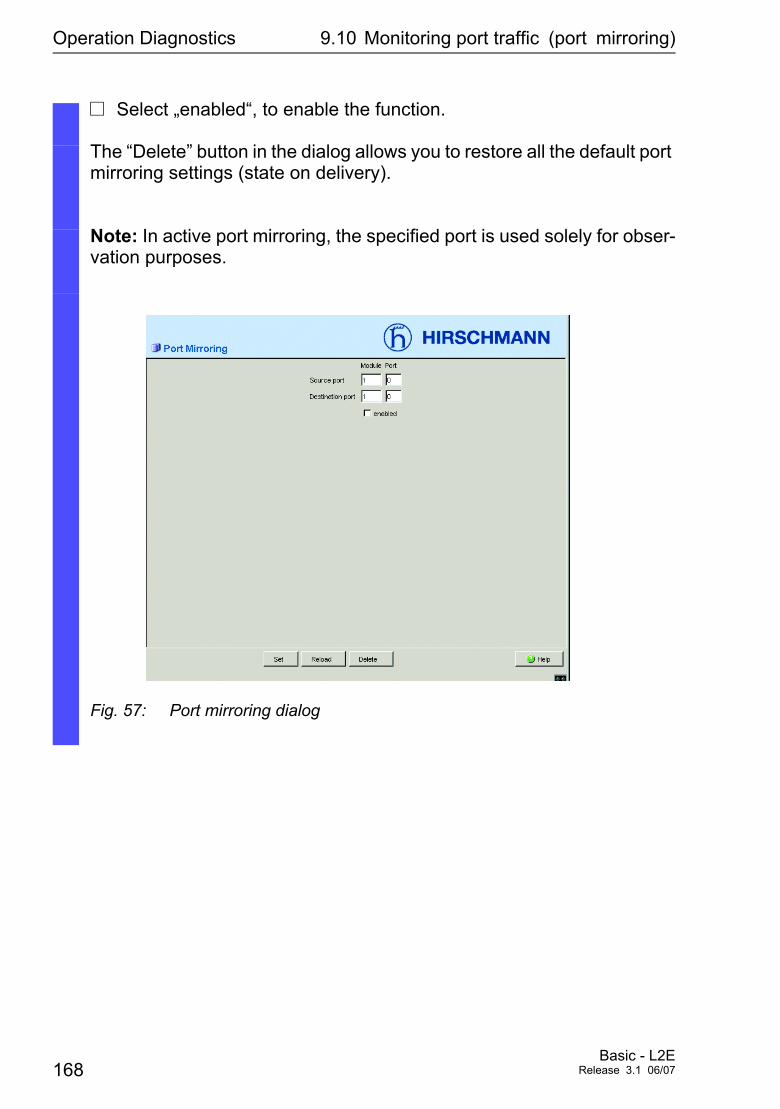
Operation Diagnostics 9.10 Monitoring port traffic (port mirroring)
V Select „enabled“, to enable the function.
The “Delete” button in the dialog allows you to restore all the default port mirroring settings (state on delivery).
Note: In active port mirroring, the specified port is used solely for obser-vation purposes.
Fig. 57: Port mirroring dialog
168Basic - L2E
Release 3.1 06/07

Setting up the configuration
Apendix A: Setting up the configuration environment
Basic - L2ERelease 3.1 06/07 169
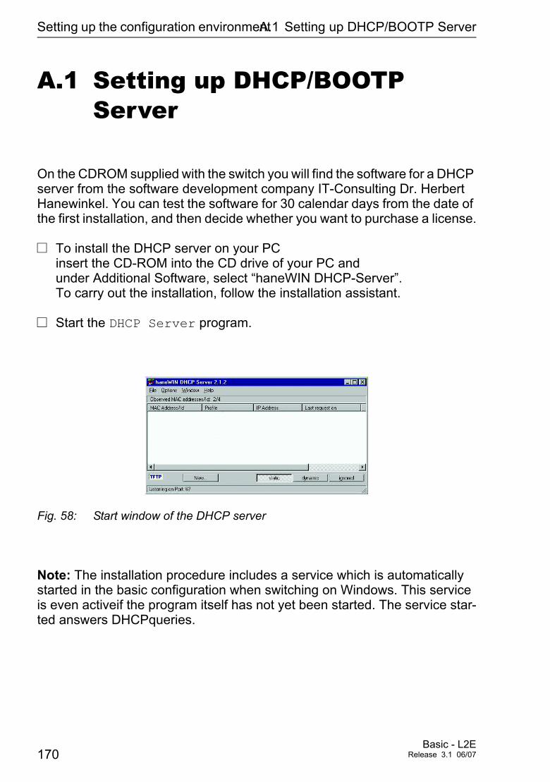
Setting up the configuration environmentA.1 Setting up DHCP/BOOTP Server
A.1 Setting up DHCP/BOOTP Server
On the CDROM supplied with the switch you will find the software for a DHCP server from the software development company IT-Consulting Dr. Herbert Hanewinkel. You can test the software for 30 calendar days from the date of the first installation, and then decide whether you want to purchase a license.
V To install the DHCP server on your PC insert the CD-ROM into the CD drive of your PC and under Additional Software, select “haneWIN DHCP-Server”. To carry out the installation, follow the installation assistant.
V Start the DHCP Server program.
Fig. 58: Start window of the DHCP server
Note: The installation procedure includes a service which is automatically started in the basic configuration when switching on Windows. This service is even activeif the program itself has not yet been started. The service star-ted answers DHCPqueries.
170Basic - L2E
Release 3.1 06/07
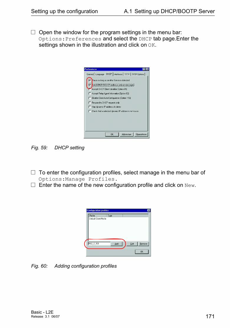
Setting up the configuration A.1 Setting up DHCP/BOOTP Server
V Open the window for the program settings in the menu bar: Options:Preferences and select the DHCP tab page.Enter the settings shown in the illustration and click on OK.
Fig. 59: DHCP setting
V To enter the configuration profiles, select manage in the menu bar of Options:Manage Profiles.
V Enter the name of the new configuration profile and click on New.
Fig. 60: Adding configuration profiles
Basic - L2ERelease 3.1 06/07 171
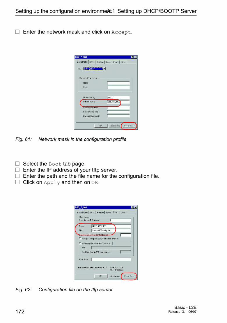
Setting up the configuration environmentA.1 Setting up DHCP/BOOTP Server
V Enter the network mask and click on Accept.
Fig. 61: Network mask in the configuration profile
V Select the Boot tab page. V Enter the IP address of your tftp server.V Enter the path and the file name for the configuration file.V Click on Apply and then on OK.
Fig. 62: Configuration file on the tftp server
172Basic - L2E
Release 3.1 06/07
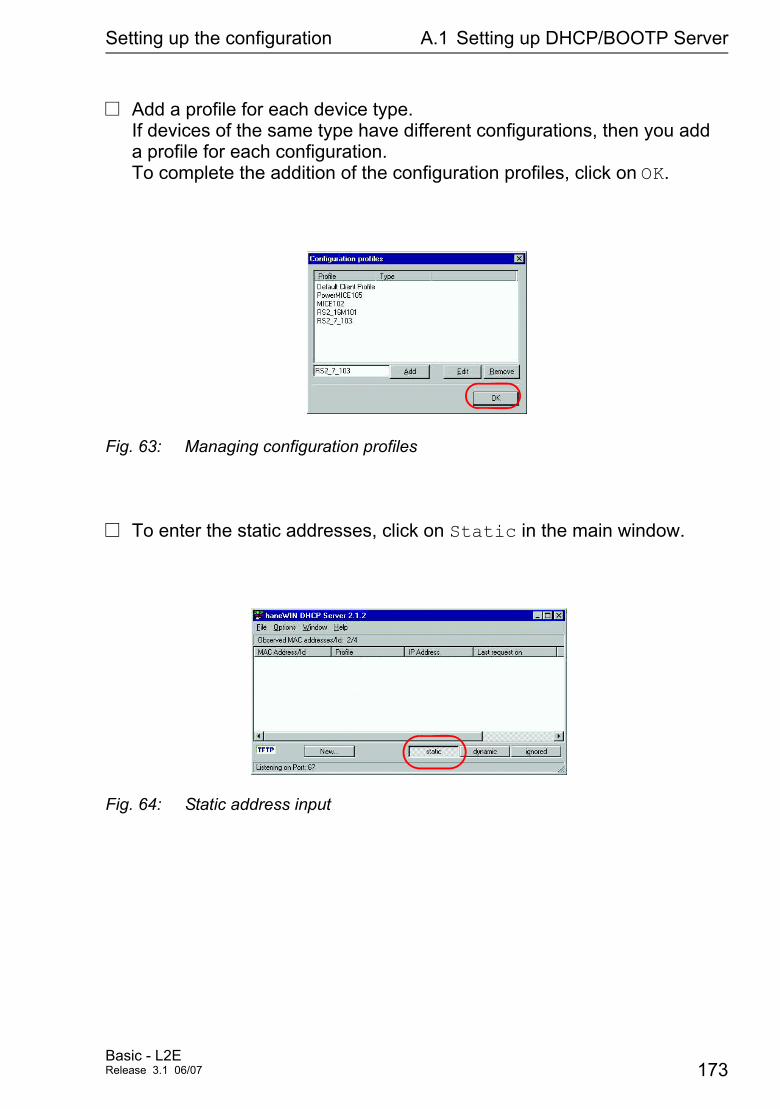
Setting up the configuration A.1 Setting up DHCP/BOOTP Server
V Add a profile for each device type. If devices of the same type have different configurations, then you add a profile for each configuration. To complete the addition of the configuration profiles, click on OK.
Fig. 63: Managing configuration profiles
V To enter the static addresses, click on Static in the main window.
Fig. 64: Static address input
Basic - L2ERelease 3.1 06/07 173
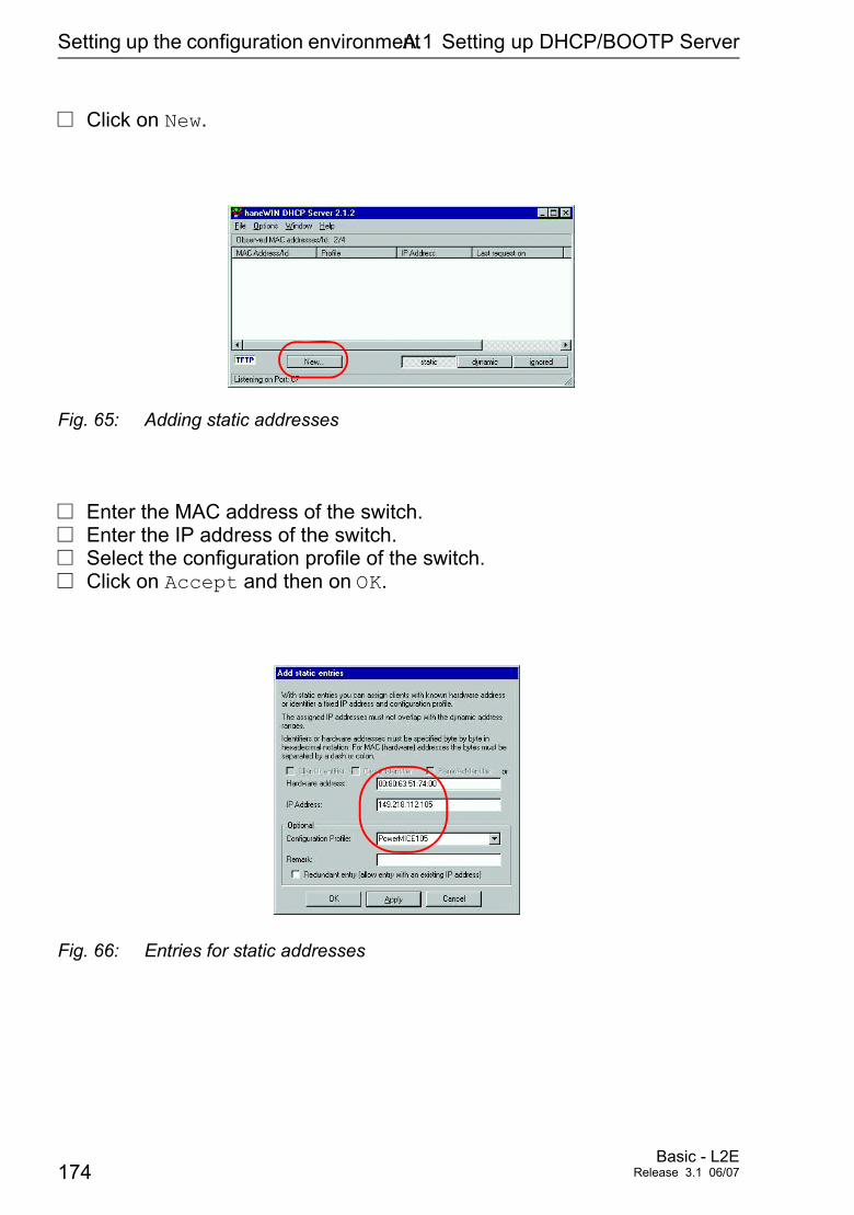
Setting up the configuration environmentA.1 Setting up DHCP/BOOTP Server
V Click on New.
Fig. 65: Adding static addresses
V Enter the MAC address of the switch.V Enter the IP address of the switch.V Select the configuration profile of the switch.V Click on Accept and then on OK.
Fig. 66: Entries for static addresses
174Basic - L2E
Release 3.1 06/07
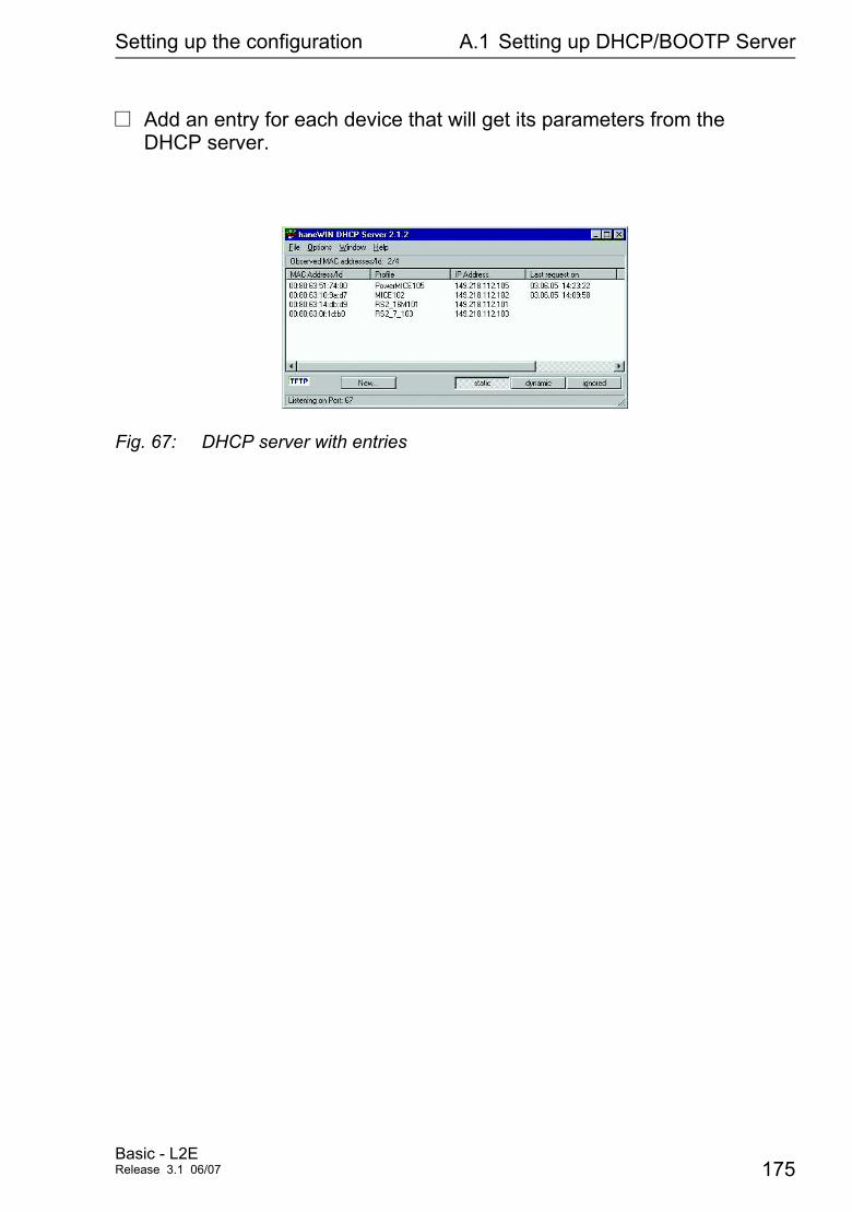
Setting up the configuration A.1 Setting up DHCP/BOOTP Server
V Add an entry for each device that will get its parameters from the DHCP server.
Fig. 67: DHCP server with entries
Basic - L2ERelease 3.1 06/07 175
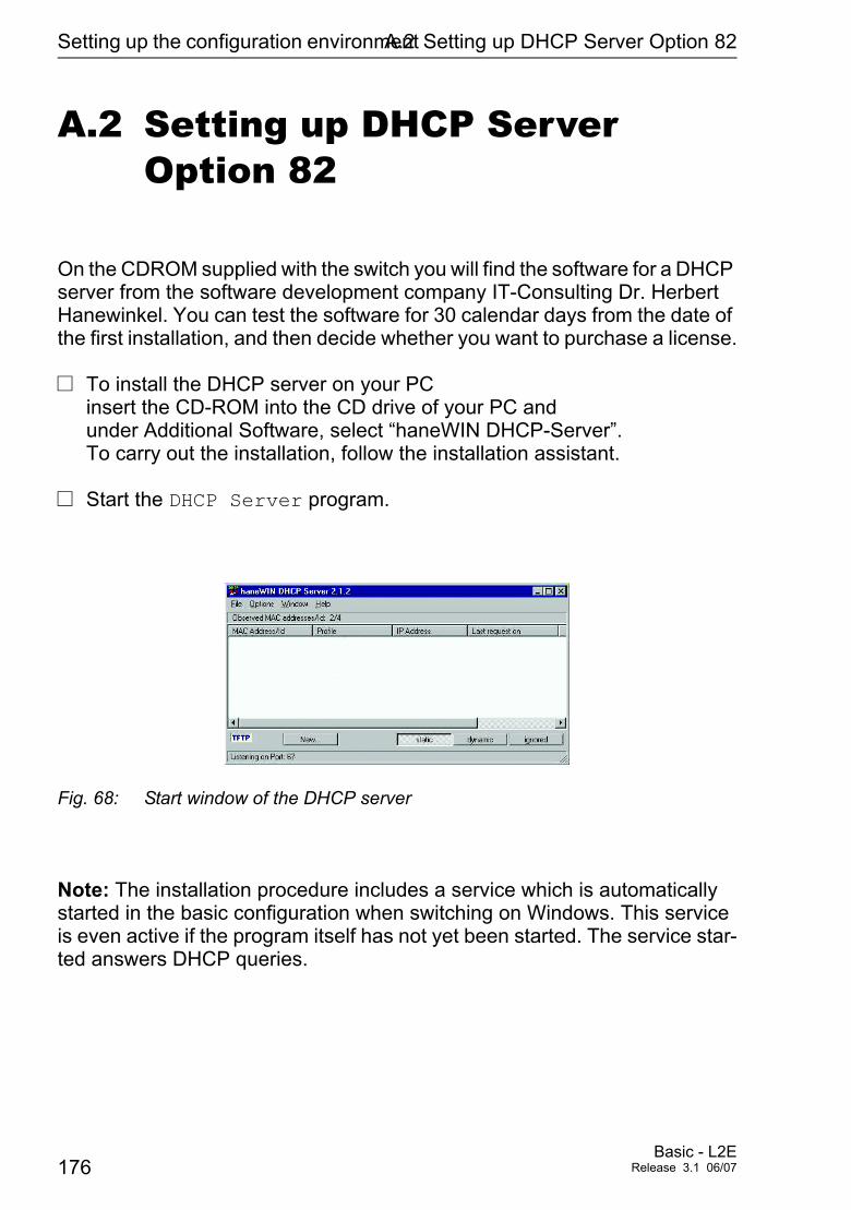
Setting up the configuration environmentA.2 Setting up DHCP Server Option 82
A.2 Setting up DHCP Server Option 82
On the CDROM supplied with the switch you will find the software for a DHCP server from the software development company IT-Consulting Dr. Herbert Hanewinkel. You can test the software for 30 calendar days from the date of the first installation, and then decide whether you want to purchase a license.
V To install the DHCP server on your PC insert the CD-ROM into the CD drive of your PC and under Additional Software, select “haneWIN DHCP-Server”. To carry out the installation, follow the installation assistant.
V Start the DHCP Server program.
Fig. 68: Start window of the DHCP server
Note: The installation procedure includes a service which is automatically started in the basic configuration when switching on Windows. This service is even active if the program itself has not yet been started. The service star-ted answers DHCP queries.
176Basic - L2E
Release 3.1 06/07
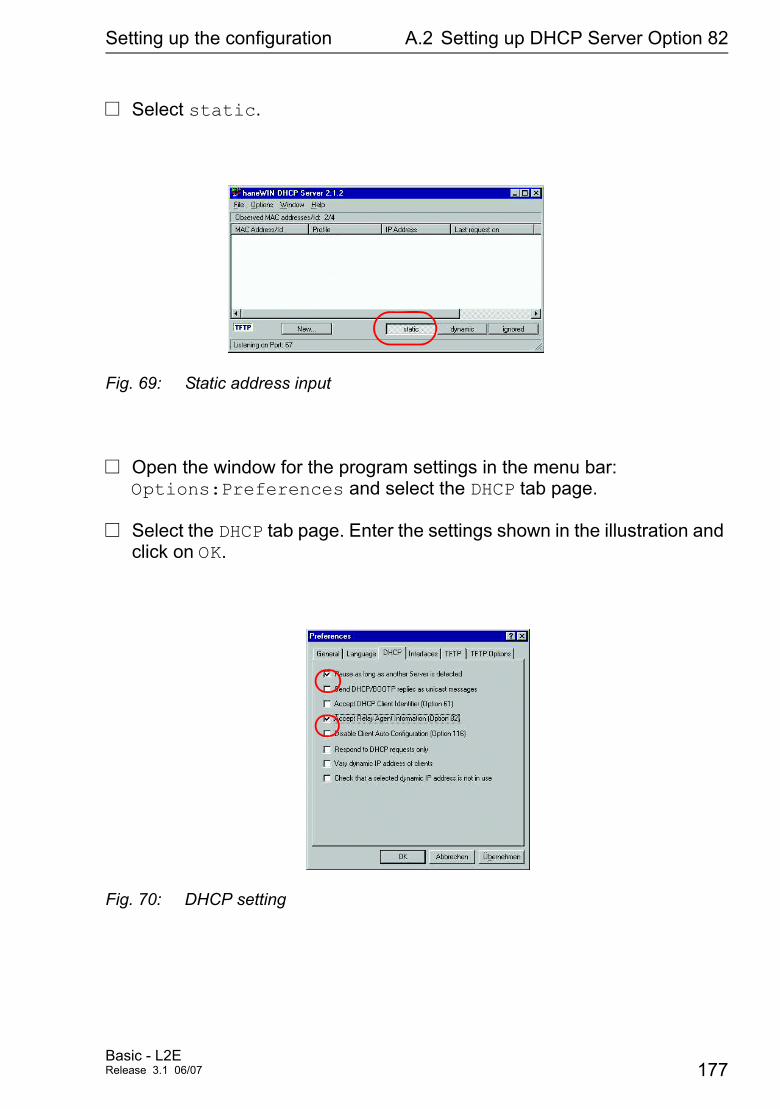
Setting up the configuration A.2 Setting up DHCP Server Option 82
V Select static.
Fig. 69: Static address input
V Open the window for the program settings in the menu bar: Options:Preferences and select the DHCP tab page.
V Select the DHCP tab page. Enter the settings shown in the illustration and click on OK.
Fig. 70: DHCP setting
Basic - L2ERelease 3.1 06/07 177
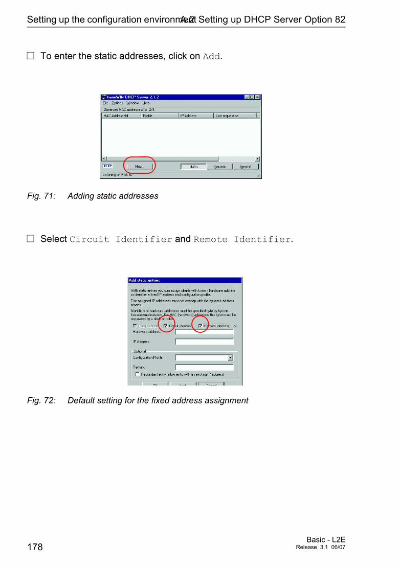
Setting up the configuration environmentA.2 Setting up DHCP Server Option 82
V To enter the static addresses, click on Add.
Fig. 71: Adding static addresses
V Select Circuit Identifier and Remote Identifier.
Fig. 72: Default setting for the fixed address assignment
178Basic - L2E
Release 3.1 06/07
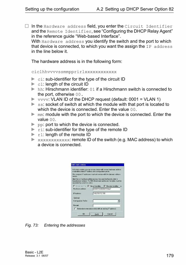
Setting up the configuration A.2 Setting up DHCP Server Option 82
V In the Hardware address field, you enter the Circuit Identifier and the Remote Identifier, see “Configuring the DHCP Relay Agent” in the reference guide “Web-based Interface”. With Hardware address you identify the switch and the port to which that device is connected, to which you want the assign the IP address in the line below it.
The hardware address is in the following form:
ciclhhvvvvssmmpprirlxxxxxxxxxxxx
D ci: sub-identifier for the type of the circuit IDD cl: length of the circuit IDD hh: Hirschmann identifier: 01 if a Hirschmann switch is connected to
the port, otherwise 00.D vvvv: VLAN ID of the DHCP request (default: 0001 = VLAN 1)D ss: socket of switch at which the module with that port is located to
which the device is connected. Enter the value 00.D mm: module with the port to which the device is connected. Enter the
value 00.D pp: port to which the device is connected.D ri: sub-identifier for the type of the remote IDD rl: length of the remote IDD xxxxxxxxxxxx: remote ID of the switch (e.g. MAC address) to which
a device is connected.
Fig. 73: Entering the addresses
Basic - L2ERelease 3.1 06/07 179
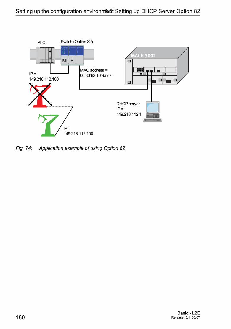
Setting up the configuration environmentA.2 Setting up DHCP Server Option 82
Fig. 74: Application example of using Option 82
PLC Switch (Option 82)
IP =149.218.112.100
IP =149.218.112.100
MAC address =00:80:63:10:9a:d7
DHCP serverIP =149.218.112.1
�� �� ��
MACH 3002MICE
180Basic - L2E
Release 3.1 06/07
Setting up the configuration A.3 tftp server for software updates
A.3 tftp server for software updates
On delivery, the switch software is held in the flash memory. The Switch boots the software from the flash memory.
Software updates can be realized via a tftp server. This presupposes that a tftp server has been installed in the connected network and that it is active.
Note: An alternative to the tftp update is the http update. The http update saves you having to configure the tftp server.
The Switch requires the following information to be able to make a software update from the tftp server:D its own IP address (entered permanently),D the IP address of the tftp server or gateway to the tftp server,D the path in which the operating system of the tftp server is kept
File transfer between Switch and tftp server is handled by way of the Trivial File Transfer Protocol (tftp).
Management station and tftp server may be made up of one or more computers.
Preparation of the tftp server for the Switch software involves the following steps:
D Setting-up the Switch directories and copying the Switch software
D Setting-up the tftp process
Basic - L2ERelease 3.1 06/07 181
Setting up the configuration environmentA.3 tftp server for software updates
A.3.1 Setting up the tftp process
General prerequisites:
D The local address of the Switch and the IP address of the tftp servers or the gateway are known to the Switch.
D The TCP/IP stack with tftp is installed on tftp server.
The following sections contain information on setting up the tftp process, arranged according to operating system and application.
U SunOS and HPV First check whether the tftp daemon (background process) is running,
i.e. whether the file /etc/inetd.conf contains the following line (see Fig. 75) and whether the status of this process is “IW”:
SunOS
tftp dgram udp wait root /usr/etc/in.tftpd in.tftpd -s /tftpboot
HP
tftp dgram udp wait root /usr/etc/in.tftpd tftpd
If the process is not in the file, or if the related line is commented out (#), modify /etc/inetd.conf accordingly and then re-initialize the INET daemon. This is done with the command “kill -1 PID”, where PID is the process ID of inetd. This re-initialization can be executed automatically by inputting the following UNIX commands:
SunOS
ps -ax | grep inetd | head -1 | awk -e {print $1} | kill -1
HP
/etc/inetd -c
182Basic - L2E
Release 3.1 06/07
Setting up the configuration A.3 tftp server for software updates
You can obtain additional information about the tftpd daemon tftpd with the UNIX command “man tftpd”.
Hinweis: The command “ps” does not always show the tftp daemon, alt-hough it is actually running.
Special steps for HP workstations:V During installation on an HP workstation, enter the user tftp in the
/etc/passwd file.
For example:
tftp:*:510:20:tftp server:/usr/tftpdir:/bin/false
tftp user ID, * is in the password field, 510 sample user ID, 20 sample group ID, tftp serverfreely selectable designation, /bin/falsemandatory entry (login shell)
V Test the tftp process with, for example: cd /tftpboot/mice tftp <tftp-Servername> get mice/mice.bin rm mice.bin
Basic - L2ERelease 3.1 06/07 183
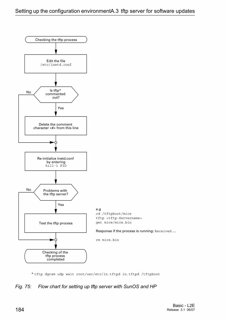
Setting up the configuration environmentA.3 tftp server for software updates
Fig. 75: Flow chart for setting up tftp server with SunOS and HP
Yes
Problems with the tftp server?
Edit the file/etc/inetd.conf
No
Delete the comment character »#« from this line
Yes
Re-initialize inetd.conf by enteringkill-1 PID
Is tftp* commented
out?
* tftp dgram udp wait root/usr/etc/in.tftpd in.tftpd /tftpboot
Checking the tftp process
No
Checking of the tftp process completed
Test the tftp process
e.gcd /tftpboot/micetftp <tftp-Servername>get mice/mice.bin
Response if the process is running: Received …
rm mice.bin
184Basic - L2E
Release 3.1 06/07
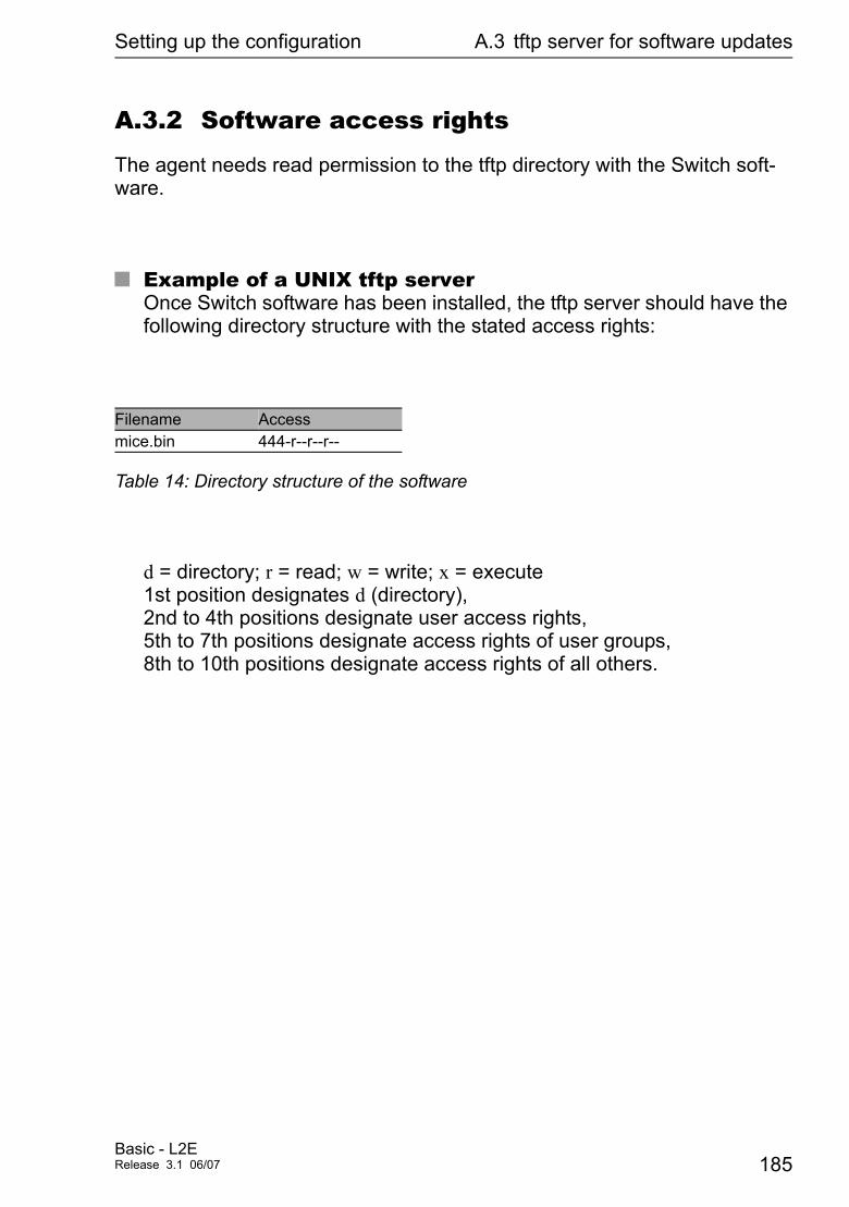
Setting up the configuration A.3 tftp server for software updates
A.3.2 Software access rights
The agent needs read permission to the tftp directory with the Switch soft-ware.
U Example of a UNIX tftp serverOnce Switch software has been installed, the tftp server should have the following directory structure with the stated access rights:
d = directory; r = read; w = write; x = execute1st position designates d (directory),2nd to 4th positions designate user access rights,5th to 7th positions designate access rights of user groups,8th to 10th positions designate access rights of all others.
Filename Accessmice.bin 444-r--r--r--
Table 14: Directory structure of the software
Basic - L2ERelease 3.1 06/07 185

Setting up the configuration environmentA.3 tftp server for software updates
186Basic - L2E
Release 3.1 06/07

General Information
Appendix B: General Information
Basic - L2ERelease 3.1 06/07 187

General Information B.1 Hirschmann Competence
B.1 Hirschmann Competence
In the longterm, product excellence alone is not an absolute guarantee of a successful project implementation. Comprehensive service makes a diffe-rence worldwide. In the current scenario of global competition, the Hirsch-mann Competence Center stands head and shoulders above the competition with its comprehensive spectrum of innovative services:
D Consulting incorporates comprehensive technical advice, from system evaluation through network planning to project planning.
D Training offers you an introduction to the technological fundamentals, pro-duct briefing and user training with certification.
D Support ranges from commissioning through the standby service to maintenance concepts.
With the Competence Center, you firmly rule out any compromise: the client-specific package leaves you free to choose the service components that you will use.
Internet: http://www.hicomcenter.com
188Basic - L2E
Release 3.1 06/07

General Information B.2 FAQ
B.2 FAQ
Answers to frequently asked questions can be found at the Hirschmann Website:
www.hirschmann.com
Under Products/Support inside Automation and Network Soluti ons is located on the pages Products the area FAQ.
For detailed information on all services offered by the Hirschmann Competence Center, please visit the Web site http://www.hicomcenter.com/.
Basic - L2ERelease 3.1 06/07 189
General Information B.3 Management Information BASE MIB
B.3 Management Information BASE MIB
The Management Information Base (MIB) is designed in the form of an ab-stract tree structure.The branching points are the object classes. The “leaves” of the MIB are called generic object classes.Wherever necessary for unambiguous identification, the generic object clas-ses are instantiated, i.e. the abstract structure is imaged on the reality, by specifying the port or the source address.Values (integers, time ticks, counters or octet strings) are assigned to these instances; these values can be read and, in some cases, modified. The object description or the object ID (OID) identifies the object class. The subidentifier (SID) is used for instantiation.
Example:The generic object class
hmPSState (OID = 1.3.6.1.4.1.248.14.1.2.1.3)
is the description of the abstract information “power supply state”. However, it is not possible to read any information from this, as the system does not know which power supply is meant.Specification of the subidentifier (2) images this abstract information onto reality (instantiates it), which means that it refers to power supply 2. A value is assigned to this instance and can then be read. The instance “get 1.3.6.1.4.1.248.14.1.2.1.3.2”, for example, returns the response “1”, which means that the power supply unit is ready for operation.
The following abbreviations are used in the MIB:
Comm Group access rightscon ConfigurationDescr DescriptionFan FanID IdentifierLwr Lower (e.g. threshold value)PS Power supplyPwr Power
190Basic - L2E
Release 3.1 06/07
General Information B.3 Management Information BASE MIB
sys SystemUI User InterfaceUpr Upper (e.g. threshold value)ven Vendor = manufacturer (Hirschmann)
Definition of the syntax terms used:
Integer An integer in the range 0 - 232
IP address xxx.xxx.xxx.xxx (xxx = integer in the range 0-255)
MAC address 12-digit hexadecimal number in accordance with ISO / IEC 8802-3
Object Identifier x.x.x.x… (e.g. 1.3.6.1.1.4.1.248…)
Octet String ASCII character string
PSID Power Supply Identification (number of the power supply unit)
TimeTicks Stopwatch Elapsed time (in seconds) = numerical value / 100 Numerical value = integer in the range 0 - 232
Timeout Time value in hundredths of a second Time value = integer in the range 0-232
Type field 4-digit hexadecimal number in accordance with ISO / IEC 8802-3
Counter Integer (0 - 232) whose value is incremented by 1 when certain events occur.
Basic - L2ERelease 3.1 06/07 191
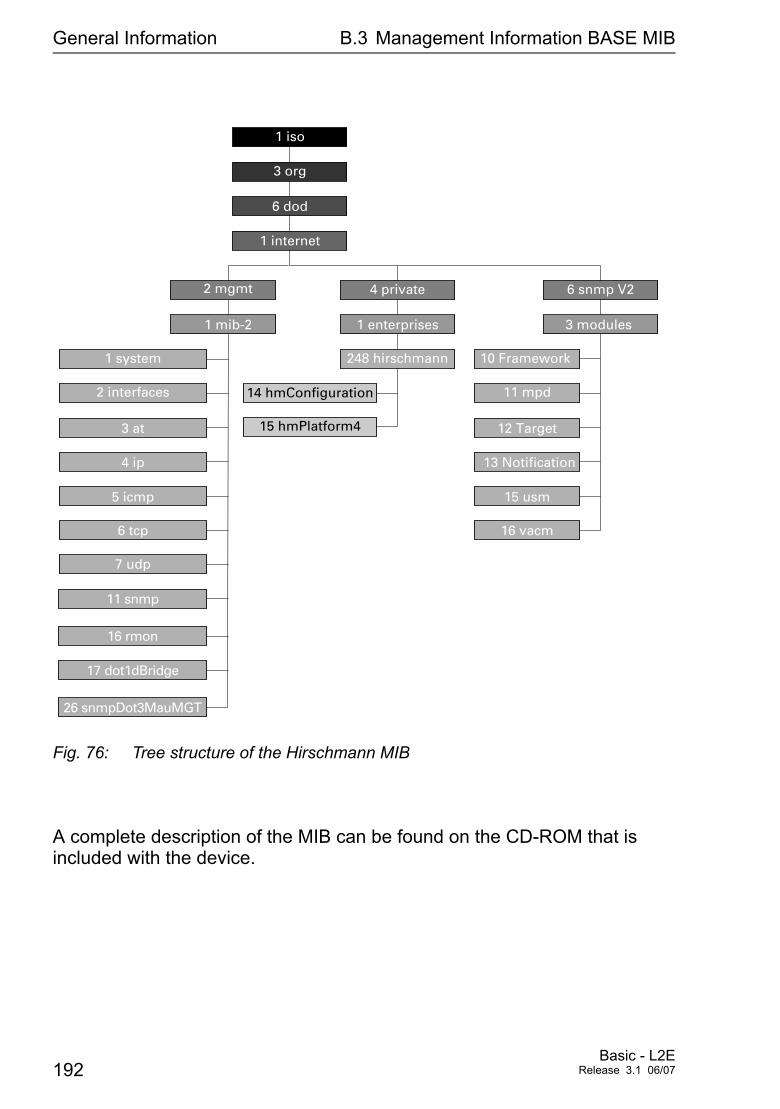
General Information B.3 Management Information BASE MIB
Fig. 76: Tree structure of the Hirschmann MIB
A complete description of the MIB can be found on the CD-ROM that is included with the device.
1 internet
1 iso
3 org
6 dod
2 mgmt
1 enterprises
248 hirschmann
4 private
3 modules
10 Framework
6 snmp V2
1 mib-2
4 ip
2 interfaces
1 system
5 icmp
6 tcp
7 udp
16 rmon
11 snmp
26 snmpDot3MauMGT
17 dot1dBridge
14 hmConfiguration
15 hmPlatform43 at
13 Notification
11 mpd
15 usm
16 vacm
12 Target
192Basic - L2E
Release 3.1 06/07
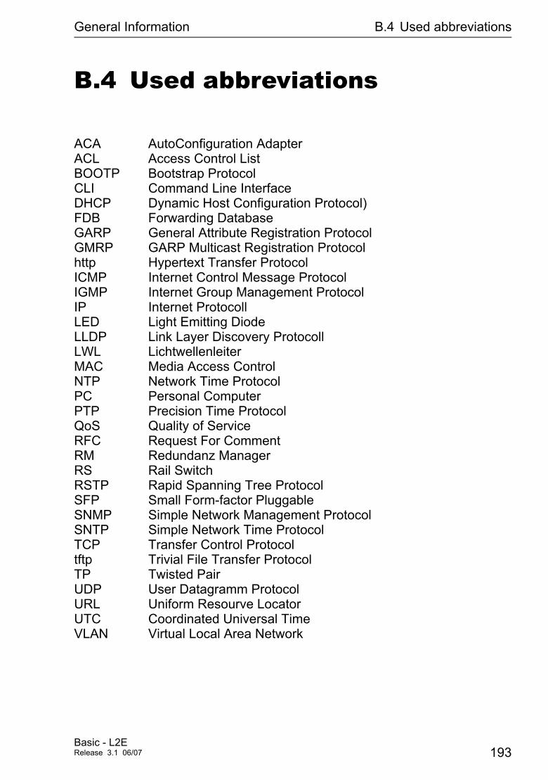
General Information B.4 Used abbreviations
B.4 Used abbreviations
ACA AutoConfiguration AdapterACL Access Control ListBOOTP Bootstrap ProtocolCLI Command Line InterfaceDHCP Dynamic Host Configuration Protocol)FDB Forwarding DatabaseGARP General Attribute Registration ProtocolGMRP GARP Multicast Registration Protocolhttp Hypertext Transfer ProtocolICMP Internet Control Message ProtocolIGMP Internet Group Management ProtocolIP Internet ProtocollLED Light Emitting DiodeLLDP Link Layer Discovery ProtocollLWL LichtwellenleiterMAC Media Access ControlNTP Network Time ProtocolPC Personal ComputerPTP Precision Time ProtocolQoS Quality of ServiceRFC Request For CommentRM Redundanz ManagerRS Rail SwitchRSTP Rapid Spanning Tree ProtocolSFP Small Form-factor PluggableSNMP Simple Network Management ProtocolSNTP Simple Network Time ProtocolTCP Transfer Control Protocoltftp Trivial File Transfer ProtocolTP Twisted PairUDP User Datagramm ProtocolURL Uniform Resourve LocatorUTC Coordinated Universal TimeVLAN Virtual Local Area Network
Basic - L2ERelease 3.1 06/07 193
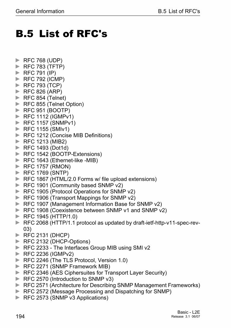
General Information B.5 List of RFC's
B.5 List of RFC's
D RFC 768 (UDP)D RFC 783 (TFTP)D RFC 791 (IP)D RFC 792 (ICMP)D RFC 793 (TCP)D RFC 826 (ARP)D RFC 854 (Telnet)D RFC 855 (Telnet Option)D RFC 951 (BOOTP)D RFC 1112 (IGMPv1)D RFC 1157 (SNMPv1)D RFC 1155 (SMIv1)D RFC 1212 (Concise MIB Definitions)D RFC 1213 (MIB2)D RFC 1493 (Dot1d)D RFC 1542 (BOOTP-Extensions)D RFC 1643 (Ethernet-like -MIB)D RFC 1757 (RMON)D RFC 1769 (SNTP)D RFC 1867 (HTML/2.0 Forms w/ file upload extensions)D RFC 1901 (Community based SNMP v2)D RFC 1905 (Protocol Operations for SNMP v2)D RFC 1906 (Transport Mappings for SNMP v2)D RFC 1907 (Management Information Base for SNMP v2)D RFC 1908 (Coexistence between SNMP v1 and SNMP v2)D RFC 1945 (HTTP/1.0)D RFC 2068 (HTTP/1.1 protocol as updated by draft-ietf-http-v11-spec-rev-
03)D RFC 2131 (DHCP)D RFC 2132 (DHCP-Options)D RFC 2233 - The Interfaces Group MIB using SMI v2D RFC 2236 (IGMPv2)D RFC 2246 (The TLS Protocol, Version 1.0)D RFC 2271 (SNMP Framework MIB)D RFC 2346 (AES Ciphersuites for Transport Layer Security)D RFC 2570 (Introduction to SNMP v3)D RFC 2571 (Architecture for Describing SNMP Management Frameworks)D RFC 2572 (Message Processing and Dispatching for SNMP)D RFC 2573 (SNMP v3 Applications)
194Basic - L2E
Release 3.1 06/07
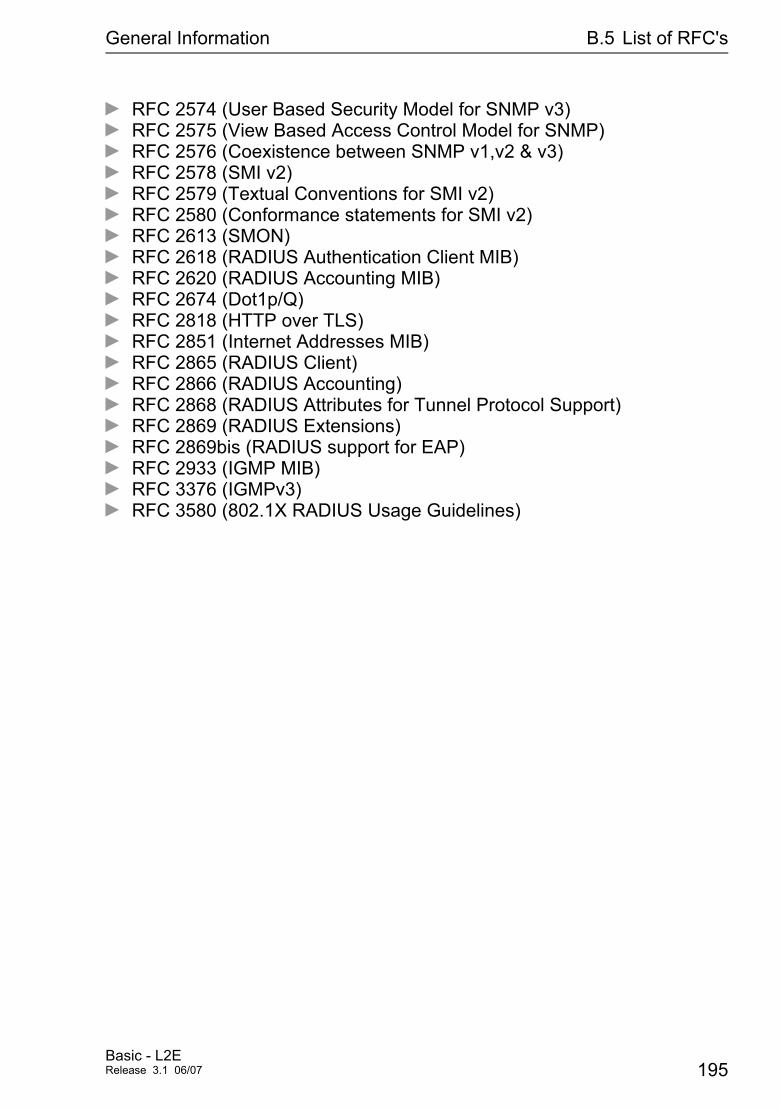
General Information B.5 List of RFC's
D RFC 2574 (User Based Security Model for SNMP v3)D RFC 2575 (View Based Access Control Model for SNMP)D RFC 2576 (Coexistence between SNMP v1,v2 & v3)D RFC 2578 (SMI v2)D RFC 2579 (Textual Conventions for SMI v2)D RFC 2580 (Conformance statements for SMI v2)D RFC 2613 (SMON)D RFC 2618 (RADIUS Authentication Client MIB)D RFC 2620 (RADIUS Accounting MIB)D RFC 2674 (Dot1p/Q)D RFC 2818 (HTTP over TLS)D RFC 2851 (Internet Addresses MIB)D RFC 2865 (RADIUS Client)D RFC 2866 (RADIUS Accounting)D RFC 2868 (RADIUS Attributes for Tunnel Protocol Support)D RFC 2869 (RADIUS Extensions)D RFC 2869bis (RADIUS support for EAP)D RFC 2933 (IGMP MIB)D RFC 3376 (IGMPv3)D RFC 3580 (802.1X RADIUS Usage Guidelines)
Basic - L2ERelease 3.1 06/07 195

General Information B.6 Based IEEE standards
B.6 Based IEEE standards
D IEEE 802.1AB Topologie Discovery (LLDP)D IEEE 802.1 D Switching, GARP, GMRP, Spanning Tree
(Supported via 802.1S implementationD IEEE 802.1 D-1998 Media access control (MAC) bridges
(includes IEEE 802.1p Priority and Dynamic Multi-cast Filtering, GARP, GMRP)
D IEEE 802.1 Q-1998 Virtual Bridged Local Area Networks (VLAN Tagging, Port Based VLANs, GVRP)
D IEEE 802.1 w.2001 Rapid Reconfiguration (RSTP)D IEEE 802.1 X Port AuthenticationD IEEE 802.3 - 2002 EthernetD IEEE 802.3 ac VLAN TaggingD IEEE 802.3 ad Link Aggregation with Static LAG and LACP sup-
port (Power MICE and MACH 4000)D IEEE 802.3 x Flow ControlD IEEE 802.1 af Power over Ethernet
196Basic - L2E
Release 3.1 06/07
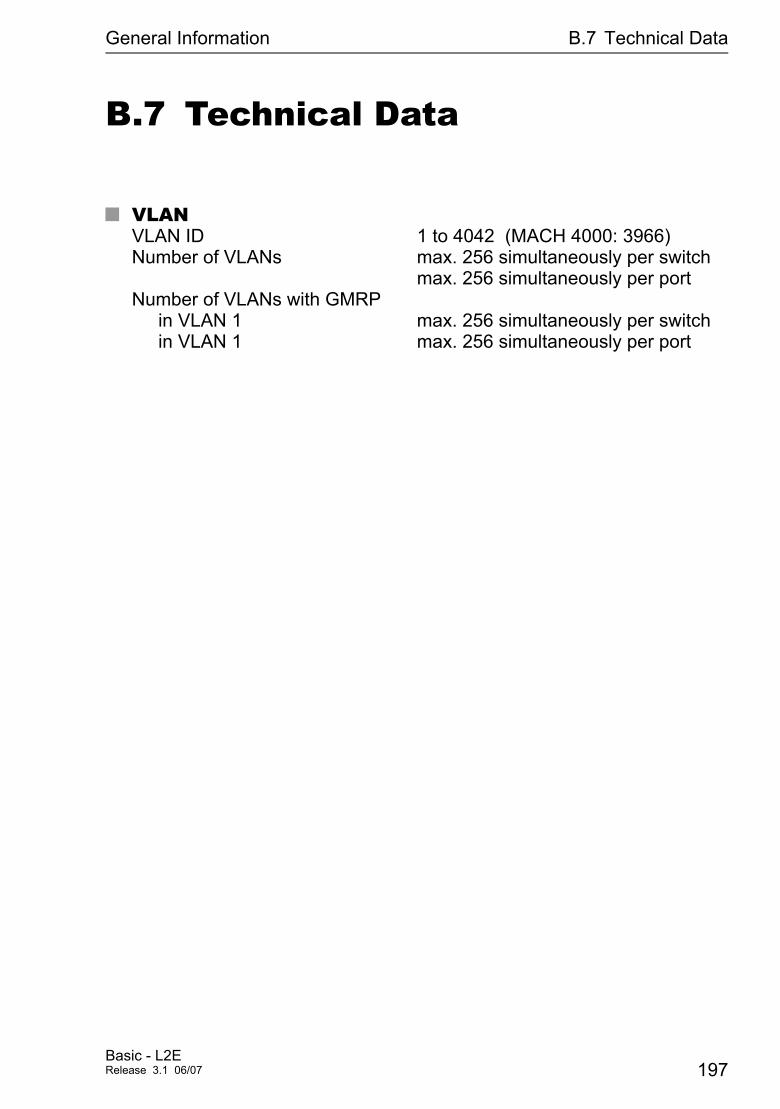
General Information B.7 Technical Data
B.7 Technical Data
U VLANVLAN ID 1 to 4042 (MACH 4000: 3966) Number of VLANs max. 256 simultaneously per switch
max. 256 simultaneously per port Number of VLANs with GMRP
in VLAN 1 max. 256 simultaneously per switch in VLAN 1 max. 256 simultaneously per port
Basic - L2ERelease 3.1 06/07 197

General Information B.8 Copyright of integrated software
B.8 Copyright of integrated soft-ware
B.8.1 Bouncy Castle Crypto APIs (Java)
The Legion Of The Bouncy CastleCopyright (c) 2000 The Legion Of The Bouncy Castle (http://www.bouncycastle.org)
Permission is hereby granted, free of charge, to any person obtaining a copy of this software and associated documentation files (the “Software”), to deal in the Software without restriction, including without limitation the rights to use, copy, modify, merge, publish, distribute, sublicense, and/or sell copies of the Software, and to permit persons to whom the Software is furnished to do so, subject to the following conditions:
The above copyright notice and this permission notice shall be included in all copies or substantial portions of the Software.
THE SOFTWARE IS PROVIDED “AS IS”, WITHOUT WARRANTY OF ANY KIND, EXPRESS OR IMPLIED, INCLUDING BUT NOT LIMITED TO THE WARRANTIES OF MERCHANTABILITY, FITNESS FOR A PARTICULAR PURPOSE AND NONINFRINGEMENT. IN NO EVENT SHALL THE AU-THORS OR COPYRIGHT HOLDERS BE LIABLE FOR ANY CLAIM, DAMA-GES OR OTHER LIABILITY, WHETHER IN AN ACTION OF CONTRACT, TORT OR OTHERWISE, ARISING FROM, OUT OF OR IN CONNECTION WITH THE SOFTWARE OR THE USE OR OTHER DEALINGS IN THE SOFTWARE.
B.8.2 LVL7 Systems, Inc.
(c) Copyright 1999-2006 LVL7 Systems, Inc. All Rights Reserved.
198Basic - L2E
Release 3.1 06/07

General Information B.9 Reader's comments
B.9 Reader's comments
What is your opinion of this manual? We are always striving to provide as comprehensive a description of our product as possible, as well as important information that will ensure trouble-free operation. Your comments and suggestions help us to further improve the quality of our documentation.
Your assessment of this manual:
excellent good satisfactory mediocre poor
Accuracy O O O O O
Readability O O O O O
Comprehensibility O O O O O
Examples O O O O O
Structure/Layout O O O O O
Completeness O O O O O
Graphics O O O O O
Drawings O O O O O
Tables O O O O O
Did you discover an error in the manual? If so, on what page?
.......................................................................................................................
.......................................................................................................................
.......................................................................................................................
.......................................................................................................................
.......................................................................................................................
.......................................................................................................................
.......................................................................................................................
Basic - L2ERelease 3.1 06/07 199

General Information B.9 Reader's comments
Suggestions for improvement and additional information:.......................................................................................................................
.......................................................................................................................
.......................................................................................................................
.......................................................................................................................
General comments:.......................................................................................................................
.......................................................................................................................
.......................................................................................................................
.......................................................................................................................
Company / Department ..........................................................................................................
Name / Telephone number ..........................................................................................................
Street ..........................................................................................................
Zip code / City ..........................................................................................................
Date / Signature ..........................................................................................................
Dear User,
Please fill out and return this page
− by fax to the number +49 (0)7127/14-1798 or − by mail to
Hirschmann Automation and Control GmbH Department AMM Stuttgarter Str. 45 - 51 72654 Neckartenzlingen Germany
200Basic - L2E
Release 3.1 06/07
Index
Appendix C: Index
AACA 37, 53, 63, 65, 146Access right 74ACD 163Address conflict 163Address Conflict Detection 163Address table 107Aging Time 107, 112Alarm 84, 144Alarm messages 142Allowed IP addesses 84Allowed MAC addresses 84APNIC 27ARIN 27Authentication 145AutoConfiguration Adapter 146
BBandwidth 110, 124Booting 16BOOTP 25, 44, 47Boundary 99Boundary clock 97Broadcast 93, 106, 110, 127Broadcast address 108Browser 22
CCD-ROM 170, 176Chassis 146CLI 75Clock 95Closed circuit 150Cold Start 145Configuration data 39, 46, 54, 57Configuration modifications 142Coupling 146
DDestination address 108, 109Destination address field 106Destination port 167Device state 147DHCP 25, 33DHCP client 43DHCP Option 82 46DHCP server 170, 176
EEgress rule 127
EtherNet/IP 9Event counters 156
FFAQ 189Faulty Device Replacement 49FDB 108Filter 108Filter table 108First installation 25Flow control 124Forwarding Database 108
Ggateway 34Generic object classes 190GMRP 109, 110Grandmaster 95
HHaneWin 170, 176Hardware address 40Hardware reset 142HiDiscovery 48, 81HIPER-Ring 146HiVision 44
IIANA 27IAONA 166IEEE 802.1 Q 119IEEE-MAC address 160IGMP 109IGMP Snooping 110Industry Protocols 9Ingress Filter 131, 138Ingress rule 127Instantiation 190Internet Assigned Numbers Authority 27Internet Service Provider 27IP address 25, 27, 33, 40, 43, 48, 81, 84, 163,
181ISO/OSI layer model 31
JJavaScript 23
LLACNIC 27Leave 112
201Basic - L2ERelease 3.1 06/07
Index
Link Down 145Link up 145LLDP 161Local clock 96Logical communication path 97Login 23
MMAC 96MAC address 43, 48, 81, 84MAC destination address 31Media module 146Member 131Member set 128Message 142Multicast 93, 110, 112, 127Multicast address 108
NNetwork address 27Network management 44Network mask 33Network topology 46NTP 90
OObject classes 190Object description 190Object ID 190Option 82 26, 46, 176Ordinary clock 97Overload protection 124
PPassword 20, 74, 75PHY layer 96Polling 142Port Configuration 69Port Mirroring 167Port Security 85, 146Port VLAN ID 127Power Supply 146Precision Time Protocol 95Preferred Master 99Priority 119, 120Priority queues 119Priority tagged frames 120PROFINET 9Protocol stack 96PTP 95PTP Preferred Master 99PTP-Subdomain 97
QQoS 119Queue 121
RReal time 87, 119Receiving port 109Redundancy 146Redundancy manager 108Reference clock 95Relay contact 150Release 61Report 112Restart 109, 156RFC 194RIPE NCC 27RMON probe 167
SSecurity Data Sheet IAONA 166Segmentation 142Service provider 27Signaling Relay 146Simple PTP Mode 99SNMP 22, 74, 75, 77, 142SNMPv1/2c 77SNTP cascade 90SNTP Client 90SNTP Server 90Software 185Source address 106Source port 167State on delivery 74Static 108Strict priority 121Subdomain 97Subidentifier 190Subnetwork 33, 107Support 189Synchronizing clocks 96System monitor 16System name 43System time 93
TTCP/IP stack 182Telnet 19Temperature threshold 146Time management 95Time stamp unit 96Topology 46Traffic classes 119Transmission security 142Trap 84, 142, 144
202Basic - L2E
Release 3.1 06/07
Index
Trap destination table 142Trivial File Transfer Protocol 181Type field 119
UUnicast 110Universal Time Coordinated 90Untagged set 128User group 127Username 20UTC 90
VV.24 19Video 121VLAN 92, 119, 126VLAN ID 47VLAN identification 127VLAN tag 119, 120, 127VoIP 121
WWeb-based interface 22Web-based management 23
Basic - L2ERelease 3.1 06/07 203

Index
204Basic - L2E
Release 3.1 06/07