Embed Size (px)
Citation preview

1
Basic Concepts in Electrochemistry

2
Electrochemical Cell ElectronsCurrent
+ -
ANODE CATHODECurrent
Voltage Source

3
Fuel Cell Electrons (2 e)Current
- +
ANODE CATHODECurrent
Electrical Load
H2 2H + + 2e ½ O2 + 2H + + 2e H2O

4
Electrolysis Cell Electrons (2 e)Current
+ -
ANODE CATHODECurrent
Voltage Source
2 H+; SO4 2-
H2O ½ O2 + 2H + + 2e 2H + + 2e H2

5
What is electrochemistry?
Electrochemistry is defined as the branch of chemistry that examines the
phenomena resulting from combined chemical and electrical effects.

6
Types of processes• This field covers:
- Electrolytic processes: Reactions in which chemical changes occur on the passage of an electrical current
- Galvanic or Voltaic processes: Chemical reactions that result in the production of electrical energy

7
Electrochemical cell
An electrochemical cell typically consists of:
- Two electronic conductors (also called electrodes)
- An ionic conductor (called an electrolyte)

8
Modes of charge transport
Charge transport in the electrodes occurs via the motion of electrons (or holes),
Charge transport in the electrolyte occurs via the motion of ions (positive
and negative)

9
Reactions – half cell and overall
At each electrode, an electrochemical reaction occurs. This reaction is called a half cell
reaction (since there are two electrodes in a typical cell at which reactions occur)
The overall chemical reaction of the cell is given by combining the two individual half
cell reactions

10
Half cell reaction types• There are two fundamental types of half cell
reactions:- Oxidation reactions - Reduction reactions
A reaction is classified as oxidation or reduction depending on the direction of electron transfer

11
Oxidation and reduction energetics

12
Oxidation• Involves the loss of an electron• Involves the transfer of electrons from the species
to the electrode
R = O + ne (1)
Oxidation is an energetic process, and occurs when the energy of the electrode dips below the
highest occupied molecular orbital of the compound – see figure part b

13
Reduction• Involves the gain of an electron• Involves the transfer of electrons from the
electrode to the species
O + ne = R (2)
Reduction is also an energetic process, and occurs when the energy of the electrode increases
above the lowest vacant molecular orbital of the compound – see figure part a

14
Example of electrochemical cell
Zinc and copper metals placed in a solution of their
respective sulfates, and separated by a
semi permeable membrane

15
Reactions• Zinc metal gets oxidized - goes into solution:
Zn = Zn 2+ + 2e (3)• Copper ions in solution – reduced; copper metal -
deposited on the copper electrode Cu2+ + 2e = Cu (4)
• Electrons for reduction obtained from the zinc electrode - external wire
• Sulfate ions [reaction (4)] migrate through the membrane, - react with the zinc ions [from (3)] -zinc sulfate
16
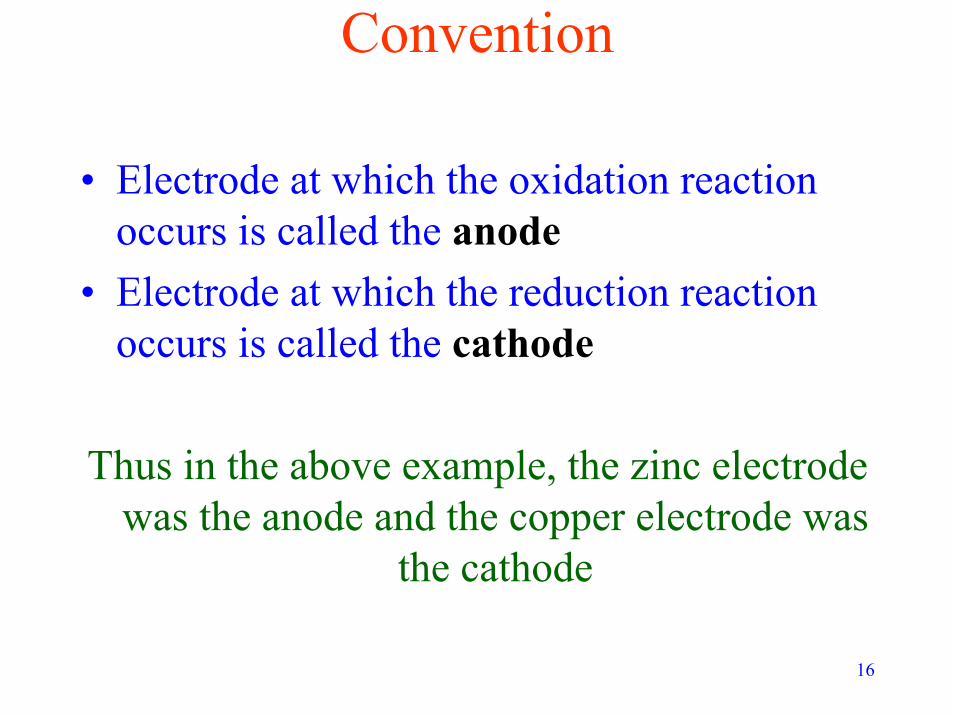
Convention
• Electrode at which the oxidation reaction occurs is called the anode
• Electrode at which the reduction reaction occurs is called the cathode
Thus in the above example, the zinc electrode was the anode and the copper electrode was
the cathode

17
Working and counter electrodesThe electrode at which the reaction of interest
occurs is called the working electrode
The electrode at which the other (coupled) reaction occurs is called the counter
electrode
A third electrode, called the reference electrode may also be used

18
What gets oxidized?• In previous example:
- Zn was oxidized- Cu was reduced
For a given set of two reversible redox reactions, Thermodynamics predicts
which reaction proceeds as an oxidation and which proceeds as a reduction
19
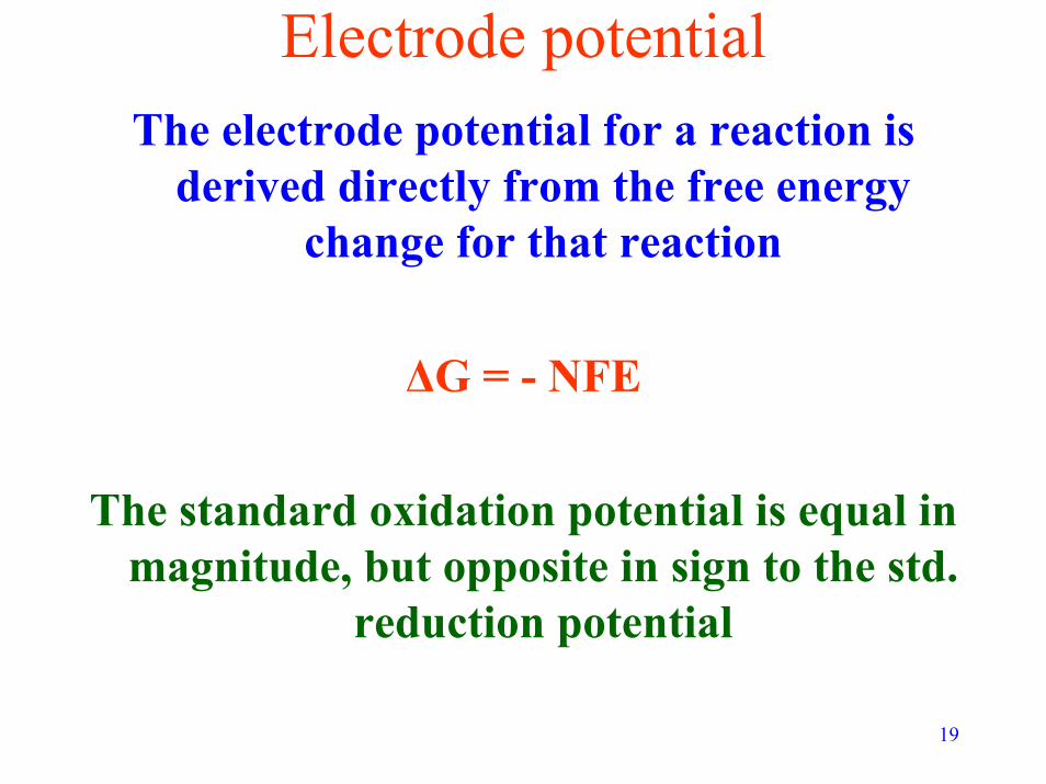
Electrode potentialThe electrode potential for a reaction is
derived directly from the free energy change for that reaction
∆G = - NFE
The standard oxidation potential is equal in magnitude, but opposite in sign to the std.
reduction potential

20
Competing reactions• For a set of 2 competing reactions:
The reaction with the lower standard reduction potential gets oxidized - the other reaction
proceeds as a reduction
Zn = Zn 2+ + 2e (3) E°red = --0.7618 V
Cu2+ + 2e = Cu (4) E°red = 0.341 V
Thus, in the above example, Zn is oxidized, and Cu is reduced

21
Rationale∆Gcell = - NFEcell
Ecell = Ecathode – E anode
For a feasible reaction: Ecell must be positive (so that ∆Gcell is negative – recall thermodynamic criterion for feasibility)
Therefore: Ecathode – E anode > 0 or Ecathode > E anode

22
• Since oxidation occurs at the anode – the species with the lower reduction potential will get oxidized
• This is to ensure that ∆Gcell is negative• This is why Zn got oxidized (and Cu
reduced) in the above example. • In this case: Ecell = 1.102. • If the reverse were to occur, Ecell would
be: -1.102, leading to a positive ∆Gcell
23
Sources of E°red values
Comprehensive listings of E°red values for
most half cell reactions are available in:
- The Lange’s Handbook of chemistry- The CRC Handbook of chemistry
and physics

24
Faraday’s law
Relationship between the quantity of current (charge) passed through a
system, and the quantity of (electro) chemical change that occurs due to the
passage of the current
25
Mathematical statementm = M I t /n F (5)
m - mass of substanceM - molecular weight of the substanceI - current passed (A)t - time for which the current is passed
(s)n - number of electrons transferred
F - Faraday constant (96475 C / eqv)

26
Key concept
The amount of chemical change is proportional to the amount of
current passed

27
Faraday’s second law
Restatement of the first law for a fixed quantity of charge passing through
the system

28
Faradaic processesAll processes that obey Faraday’s law are termed
faradaic processes
All these processes involve electron transfer at an electrode / electrolyte interface
These reactions are also called electron / charge transfer reactions
Electrodes at which these processes occur are called charge transfer electrodes

29
Nonfaradaic processesSometimes changes exist in the electrode /
electrolyte interface without charge transfer taking place
These changes are due to processes such as adsorption and desorption
Such processes are called nonfaradaicprocesses

30
No electrons flow through the electrode / electrolyte interface during nonfaradaic
processes
However, transient external currents can be generated by nonfaradaic processes

31
More on nonfaradaic processesFaradaic processes interest us the most!
Therefore, care must be taken to ensure that the effects of the nonfaradaic
processes are understood and quantified.
Some examples of nonfaradaic processes are discussed in the following slides

32
Ideally polarized electrodes
An electrode at which there is no charge transfer across the electrode / electrolyte
interface over all potential ranges is called an ideally polarized electrode
(IPE)

33
Examples of IPEsNone exist that can cover the entire potential
range in solution
A mercury electrode in contact with deaerated KCl behaves as an IPE over a potential
range of ~ 2V
Other electrodes are ideally polarized over much smaller ranges
34
Behaviour of an IPERecall – no charge transfer possible at IPE /
electrolyte interface
The behaviour of such an interface when the potential across the electrode is changed
resembles that of a plain capacitor
An IPE follows the standard capacitor equation

35
Mathematical treatmentQ = CdE (6) – capacitor equation
Q - charge stored in coloumbs (C)Cd - capacitance in farads (F) E - potential across the capacitor /IPE (V)
When voltage is applied across an IPE, the “electrical double layer” is charged until eqn. 6 is
obeyed
During charging a charging current flows through the system

36
Significance of charging currents• Contributes to total current measured• Cannot be ignored– especially for low
faradaic currents – may exceed faradaic currents in such cases
To better understand the effect of charging, we need to examine mathematically the
responses of an IPE to various electrochemical stimuli

37
Model representation of an IPE
Cd Rs
The IPE system can be represented as a capacitance (Cd) in series with the
electrolyte resistance (Rs)

38
Application of a potential step

39
Input
A potential step is applied – i.e. the potential is raised from an initial value to
a higher value, and held at the higher value
See previous fig. , bottom graph

40
Result of potential step application• The double layer is charged
Q = Cd E (6)
NOTE:The applied voltage must equal the sum of the
voltage drops across the resistor (Er) and capacitor (Ec), we have

41
E = Er + Ec (7)Applying Ohm’s law,
Er = I Rs (8)from (6),
Ec = Q/Cd (9)Therefore:
E = IRs + Q/Cd (10)

42
By definition, current is the rate of flow of charge
Therefore:I = dQ/dt (11)
Equation 10 can be rewritten as:
I = dQ/dt = -Q/RsCd + E/Rs

43
SolutionInitial condition: that the capacitor is initially
uncharged (Q = 0 at t = 0)
solution of eqn. 2 is:
Q = E Cd [1 – e (-t/RsC
d)] (13)

44
Time dependence of charging current
Differentiating eqn. 13 w.r.t. time, we get:
I = (E/Rs) * e (-t/RsC
d) (14)
Equation 14 describes the time dependence of the charging current in response to a potential step – also see following figure,
top graph

45
Graphical representation

46
Practical significanceProduct of Rs and Cd has units of time – called time
constant (τ)
For typical values of Rs and Cd, the charging current dies down to an insignificant level in a few
hundred microseconds
Any faradaic current must be measured after this time period to avoid the influence of the
charging current

47
Back to faradaic processes

48
Investigation of electrochemical behaviour
Involves holding certain variables constant while observing the trends in others
Typical variable shown in diagram

49
Variables to be consideredV
ALoad / Power Supply

50
Main aspects of interest• From a fuel cell point of view, the main
aspects of interest are:- Electrochemical kinetics- Ionic and electronic resistances
a. In electrolyte b. In electrodes
- Mass transport through the electrodes
These processes are illustrated in the following schematic

51

52
CurrentCurrent may be written as the rate of change
of charge:I = dQ/dt (15)
The number of moles (N) participating in an n electron electrochemical reaction is given
by N = Q/nF (16)

53
Reaction rate• The electrochemical reaction rate can be
written as:Rate (mol/s) = dN/dt
From 16,Rate = (1/nF) dQ/dt
From 15,Rate = I/nF (17)
Thus the current is a direct measure of the rate of electrochemical reaction

54
Reaction flux• Sometimes, it is convenient to express
quantities as a flux:• Dividing the rate (17) by the active area of
the electrode (A, cm2), we get:Flux (J, mol/cm2.s) = I/nFA
• Replacing I/A by i (current density A/cm2), we get:Flux (J, mol/cm2.s) = I/nFA = i/nF (18)

55
Polarization and overpotential• Faradaic reactions – have an equilibrium potential -
based upon reaction free energy• On passing faradaic current - the potential shifts from
this equilibrium potential• This shift is termed polarization• Extent of shift - measured by the overpotential (ή)
ή = E – Eeq, (19)

56
Polarization curvesInformation about the faradaic reaction is gained by determining current as a function
of potential or vice versa.
The resulting curves (see following figure) are called polarization curves (or V-I curves or
E-I curves).
Obtaining such curves is a critical part of fuel cell research.

57
Typical fuel cell polarization curve

58
Current Density (mA/cm2)0 5 10 15 20 25 30 35
Cel
l Vol
tage
(V)
0.0
0.5
1.0
0.0
0.5
1.0
Pola
rizat
ion
(V)
Ideal Potential
Region of Activation Polarization(Reaction Rate Loss)
Total Loss
Region of Ohmic Polarization(Resistance Loss)
Region of Concentration Polarization
(Gas Transport Loss)
Cathode Loss
Membrane Internal Resistance Loss
Anode Loss

59
Resistance in electrochemical cells

60
Types of resistance
• Electronic resistance – due to electronic current through electrodes and external circuit – can be minimized by using electron conducting materials
• Ionic resistance - due to ionic current through electrolyte – needs to be considered seriously as it leads to losses

61
Ion transport• At the anode - excess of positive ions –
build up of positive charge• At the cathode – excess of negative ions -
build up of negative charge • Buildup of ionic charge - released by the
ion transport• Positive ions move from anode to cathode
and vice versa

62
Transport numbersThe fractions of current carried by the positive and
negative ions are given by their transport numbers t+ + t- respectively
Each mole of current passed corresponds to 1 mole of electrochemical change at each electrode.
Therefore the amount of ions transported in the electrolyte also equals 1 mol. Thus:
t+ + t- = 1 (20).

63
For multiple speciesMore generally,Σ ti = 1 (21)
This equation is valid when more than one type of ion is in solution.
The transport numbers of ions are determined by the conductance (L) of the electrolyte
64
Conductance and conductivity• . The conductance of an electrolyte is given
by:L = κ A / l (22)
A - active area of contactl - length (thickness) of electrolyte matrix κ – conductivity - intrinsic property of the
electrolyte
Conductance has units of Seimens (S), and conductivity of S/cm

65
ConductivityThe conductivity of the electrolyte has a
contribution from every ion in solution
• Conductivity is proportional to:- concentration of the ion (C)- charge of ion (z) - a property that determines its migration velocity – also called mobility

66
MobilityMobility is defined as the limiting velocity
of the ion in an electric field of unit strength
Now, force exerted by an electric field of strength E is given by:
F = eE*z (23)Where e is the electronic charge

67
Opposing force • An opposing force exists due to frictional
drag. • This is represented by the Stokes equation:
Fopp = 6Πνrv (24)ν - viscosity of the solutionr - ionic radius v - velocity of the ion in solution

68
Terminal velocity of ionWhen the forces exactly counterbalance each
other, the ion attains a steady state velocity called the terminal velocity
This terminal velocity is termed the mobility (u) when the electric field
strength is unity:
u = z e / 6Πνr (25)
69
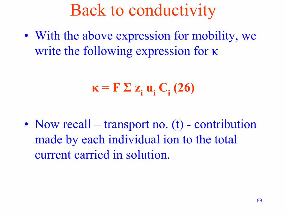
Back to conductivity• With the above expression for mobility, we
write the following expression for κ
κ = F Σ zi ui Ci (26)
• Now recall – transport no. (t) - contribution made by each individual ion to the total current carried in solution.

70
Expression for transport no.The transport no. may be represented as
the ratio of the contribution to conductivity made by a particular ion to
the total conductivity of the solution
Thus:ti = zi ui Ci / Σ zi ui Ci (27)
71
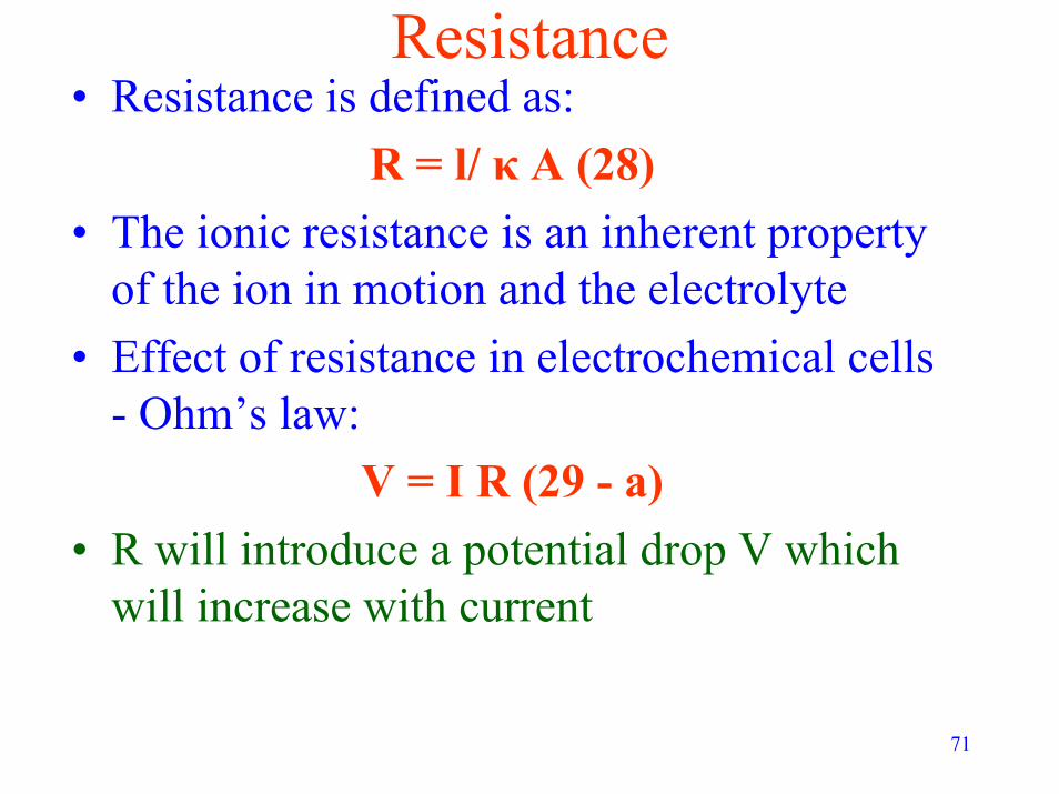
Resistance• Resistance is defined as:
R = l/ κ A (28)• The ionic resistance is an inherent property
of the ion in motion and the electrolyte• Effect of resistance in electrochemical cells
- Ohm’s law:V = I R (29 - a)
• R will introduce a potential drop V which will increase with current

72
Ohm’s Law• More appropriately Ohm’s law is expressed
as:
I = κ (dΦ/dx) (29-b)
where δφ(x)/δx - potential gradient

73
Minimizing R, IR Compensation• R can be minimized by:
- minimizing distance between electrodes- increasing area of contact (not preferred –
this is governed by many other factors)• Need to realize – some portion of R will always
remain. So realistically:Emeasured = Ecathode – E anode – IR (30)
• If the value of R is known, one can compensate for ohmic drop – the compensated E is a closer representation of the actual E:
Ecompensated /actual = Emeasured + IR (31)

74
Sources of IR in the fuel cellIR compensation is critical while analyzing fuel cell
data for kinetic and transport parameters.
Ohmic drops occur due to IR in the electrolyte and the electrodes – the IR in the electrode
should not be neglected!
IR compensation in both the electrolyte and the electrode shall be discussed in future lectures

75
Typical fuel cell polarization curve

76
Current Density (mA/cm2)0 5 10 15 20 25 30 35
Cel
l Vol
tage
(V)
0.0
0.5
1.0
0.0
0.5
1.0
Pola
rizat
ion
(V)
Ideal Potential
Region of Activation Polarization(Reaction Rate Loss)
Total Loss
Region of Ohmic Polarization(Resistance Loss)
Region of Concentration Polarization
(Gas Transport Loss)
Cathode Loss
Membrane Internal Resistance Loss
Anode Loss

77
Mass transport in electrochemical cells

78
Modes of mass transport • There are 3 fundamental modes of mass transport
in solution. They are:- Migration – this is the motion of a charge
body (such as an ion) under the influence of an electrical potential gradient
- Diffusion – this is the motion of a species under the influence of a chemical potential gradient
- Convection – this is hydrodynamic transport either due to density gradients (natural convection) or due to external means such as stirring (forced convection)

79
Governing equation• The governing equation for mass transfer is the Nernst
–Plank equation. For one (x) dimension (and one species):
J (x) = -D [δC(x)/δx] – [z F/RT][D*C δφ(x)/δx] + C*v(x) (32)
J - flux in mol / cm2.sD - diffusion coefficient (cm2/s)δC(x)/δx - concentration gradientδφ(x)/δx - potential gradientv - velocity with which an element of solution moves in the x
dimension

80
Current vs. flux• Faraday’s law - current produced– proportional
to the number of moles of reactant in solutionm = M I t /n F (5)
Can rewrite as: I / nFA = m/MtA = N/tA = J (33)
Where N = no. of moles
Do not confuse N with n, the no. of electrons transferred

81
The mass transport limit

82
The mass transport limit• Recall – also see previous diagram – that
reactants are consumed at the electrode
• The larger the current, the faster the rate of consumption – Faraday’s law
• The reactants arrive at the electrode via transport from the bulk
83
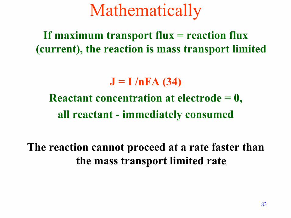
MathematicallyIf maximum transport flux = reaction flux
(current), the reaction is mass transport limited
J = I /nFA (34)Reactant concentration at electrode = 0,
all reactant - immediately consumed
The reaction cannot proceed at a rate faster than the mass transport limited rate

84
• Assume - no convective mass transport, negligible transport due to migration
• Flux at the electrode may be written as:
J = - D(dC/dx)x=0 (35)
D is the diffusion coefficient of the reactant

85
The Nernst diffusion layerThin layer that lies intermediate bounds the
electrodes and the bulk)

86
Nernst diffusion theory
• A thin layer of electrolyte (thickness δ) in contact with the electrode surface - ion transfer controlled solely by diffusion.
• Concentration of species - maintained constant outside this layer (in the “bulk”) by convective transfer.

87
• Assume - linear conc. gradient in the Nernst diffusion layer
• Eqn. 35 can be rewritten as:
J = [D/δ][C* -C(x=0)] (36)
δ - thickness of the Nernst diffusion layerC* - bulk concentration of the reactant

88
The mass transfer coefficient• Difficult to obtain precisely values of δ• Therefore δ is grouped along with D to
yield a new constant
km = D/ δ (37)
km is called the mass transfer coefficient (units: cm/s)

89
• Now:J = I /nFA (34)
• Combining eqns. 34, 36 and 37, we have:
I/nFA = km[C* -C(x=0)] (38)
Current dependence on reactant concentration

90
The limiting currentAs reaction proceeds faster- at some point all the
reactant that reaches the electrode - consumedimmediately
At this point [C(x=0)] is zero, and the current levels off. Can be written as:
Il = nFAkmC* (39)
Il is called the limiting current

91
• Relationship between surface and bulk concentrations – from equations 38 and 39:
C(x=0)/C* = [1 – (I/Il)] (40)• Substituting for C* (39),
C(x=0)= [(Il – I)/(nFAkm)] (41)
Both equations reiterate that surface concentration = 0 at the limiting current

92
Significance of Il • Maximum current obtainable for given set
of conditions• Very important in fuel cell operation• Generally, higher Il implies lower mass
transport losses – higher efficiency
Significant research efforts devoted to enhancing Il in PEM systems

93
Typical fuel cell polarization curve
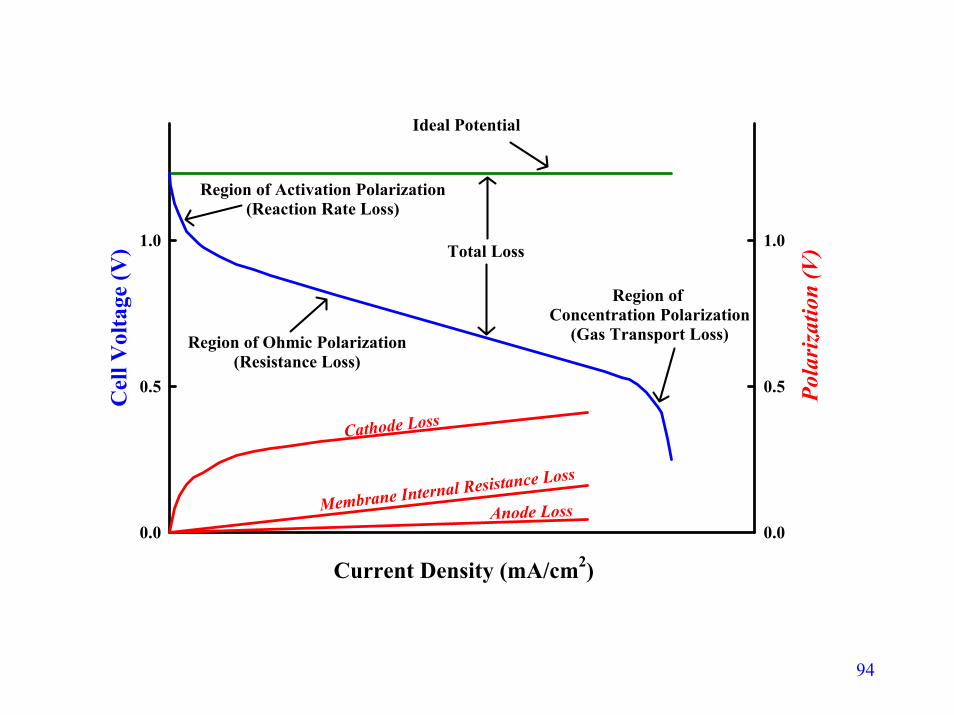
94
Current Density (mA/cm2)0 5 10 15 20 25 30 35
Cel
l Vol
tage
(V)
0.0
0.5
1.0
0.0
0.5
1.0
Pola
rizat
ion
(V)
Ideal Potential
Region of Activation Polarization(Reaction Rate Loss)
Total Loss
Region of Ohmic Polarization(Resistance Loss)
Region of Concentration Polarization
(Gas Transport Loss)
Cathode Loss
Membrane Internal Resistance Loss
Anode Loss

95
Common electrochemical experiments

96
Potentiostat
Reference Electrode
E
POTENTIAL MONITOR
Feedback Control Signal I
Working Electrode
Counter Electrode

97
Reference electrodes - SHEAn ideal reference electrode is one that
maintains a constant potential irrespective of the amount of current (if any) that is
passed through it
• Standard hydrogen electrode (NHE) –simplest reference electrodes
• This electrodes potential (by definition) is 0 V

98
• Electrode process in SHE:H+ (aq, a=1) ½ H2 (g, 1atm)
• Consists of a platinum electrode immersed in a solution with a hydrogen ion concentration of 1M.
• The platinum electrode is made of a small square of platinum foil which is
• Hydrogen gas, at a pressure of 1 atmosphere, is bubbled around the electrode
± e

http://www.owlnet.rice.edu 99
SHE
Very difficult to obtain unit activity in
practice

100
Other reference electrodes• The SHE – not widely used – difficult to
obtain solution of 1M activity.• Saturated Calomel Electrode (SCE)– very
popular:- Electrode is mercury coated with
calomel (Hg2Cl2)- Electrolyte is a solution of potassium
chloride and saturated calomelHg2Cl2(s) 2 Hg (l) +2 Cl- (aq)±2 e

http://everyscience.com/Chemistry 101
SCE
l

102
Linear Sweep Voltammetry (LSV)• Hydrogen gas passed through counter /
reference electrode (anode) nitrogen passed through cathode
• Working electrode – fuel cell cathode subjected to a potential sweep from an initial to a final voltage (typically 1 –800 mV)
• Sweep done using a potentiostat• Fixed sweep rate – 4 mV/s• Faradaic current monitored

103
Input Function
E2 = 800 mV
4 mV/sV
E1 = 1 mV
t
Hydrogen – only species present – crosses over from anode to cathode through the membrane –gets oxidized at the cathode at positive potentials (above 0 V)

104
Output
Working Electrode Potential (V)
0.0 0.2 0.4 0.6 0.8 1.0
Cur
rent
Den
sity
(mA
/cm
2 )
-100
-80
-60
-40
-20
0
20
Data obtained in a PEM fuel cell at room temperature

105
Response• When the potential is 0 V
- no net faradaic current
• When the potential exceeds 0V- faradaic oxidation H2 = H+ + e
• As potential moves to more positive values- “overpotential” / electrochemical driving
force for oxidation increases- reaction proceeds faster until it hits the mass
transport limit – since hydrogen oxidation kinetics are fast, this limit is quickly attained

106
Mass transport limit• Above a certain E, reaction becomes mass transport
limited – see output figure
In the case of limiting current behaviour, the current can be converted into a reactant flux
using Faraday’s law
J (H2) [mols/cm2-s] = * i /n F
Where i = 1 mA/cm2 (from voltammogram)

107
Additional details• The experiment is typically done at a low sweep
rate ( 1- 4 mV/s or even lower)• This is to ensure that the Nernst diffusion layer
has the time required to grow out from the electrode
• This results in “true” limiting current behaviour• In practice, it is better to start the sweep at higher
potentials to avoid effects of hydrogen evolution
The utility of LSV in fuel cell research will be further discussed in future lectures
108
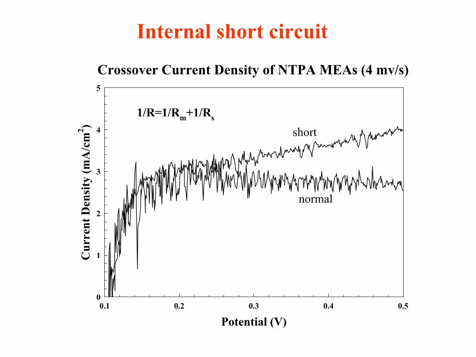
Internal short circuit
Crossover Current Density of NTPA MEAs (4 mv/s)
Potential (V)0.1 0.2 0.3 0.4 0.5
Cur
rent
Den
sity
(mA
/cm
2 )
0
1
2
3
4
5
normal
short1/R=1/Rm+1/Rs

109
Cyclic voltammetry• Potential sweep experiment (similar to LSV)• Additional reverse sweep incorporated• Input function:
- start from E = E1- sweep up to E = E2 - sweep down, back to E = E1
• Done using a potentiostat• Fixed sweep rate• Faradaic current monitored

http://www-biol.paisley.ac.uk/marco 110
E1
E2 Typical voltammogram in electrochemical systems
Input
O + ne R
R O + ne
ERedox Reaction :
O + ne R
Output
111
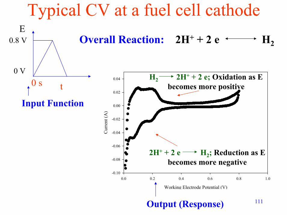
Typical CV at a fuel cell cathode
Working Electrode Potential (V)
0.0 0.2 0.4 0.6 0.8 1.0
Cur
rent
(A)
-0.10
-0.08
-0.06
-0.04
-0.02
0.00
0.02
0.04
2H+ + 2 e H2
H2 2H+ + 2 e; Oxidation as E becomes more positive
2H+ + 2 e H2; Reduction as E becomes more negative
Overall Reaction:
Input Function
0 s
E0.8 V
0 V
t
Output (Response)

112
Response – Fuel cell cathode CV• Resultant current behaviour on the forward
sweep - same as discussed for LSV – H2gets oxidized to give H+ and electrons
• Behaviour on the reverse sweep – the opposite redox phenomenon occurs – H+
gets reduced (gaining electrons in the process) to give H2
• Peak symmetry – indication of reaction reversibility

113
Additional details• Sweep rates (v) employed are typically
higher than those in LSV (~ 20-30mV/s as opposed to 1-4 mV/s)
• peak height scales as v 0.5
• Thus larger v – better defined peaks
Need to ensure sweep rate is not too high -system tends to become quasi-reversible
or irreversible

114
Applications• Studying the reversibility of reactions and
redox behaviour of compounds• Used to obtain quantitative information
about the extent of reaction occurring on a surface
• In fuel cells – used to determine electrochemically active surface area of catalyst