Embed Size (px)
Citation preview
1
BASIC CIVIL ENGINEERING
RBC2B002
2-0-0
B.Tech 2nd SEMESTER
All Branches
Prepared by
Rajesh Kumar Sahu
Sr. Lect Dept.of Civil Engineering
P.K.A.C.E., Bargarh
2
MODULE 1
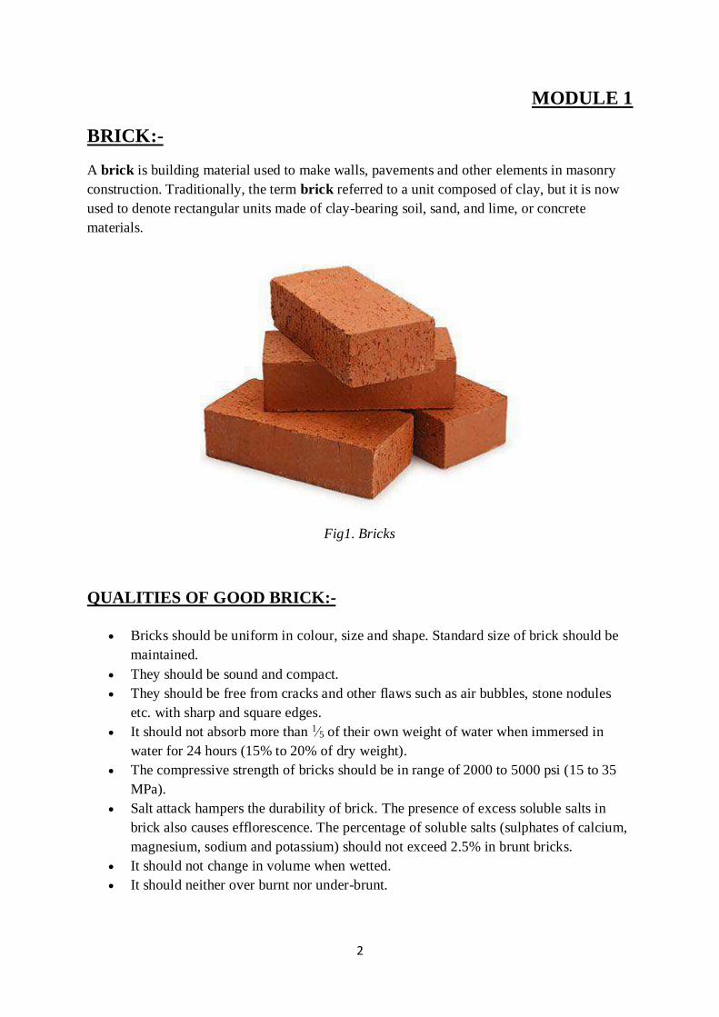
BRICK:-
A brick is building material used to make walls, pavements and other elements in masonry
construction. Traditionally, the term brick referred to a unit composed of clay, but it is now
used to denote rectangular units made of clay-bearing soil, sand, and lime, or concrete
materials.
Fig1. Bricks
QUALITIES OF GOOD BRICK:-
Bricks should be uniform in colour, size and shape. Standard size of brick should be
maintained.
They should be sound and compact.
They should be free from cracks and other flaws such as air bubbles, stone nodules
etc. with sharp and square edges.
It should not absorb more than 1⁄5 of their own weight of water when immersed in
water for 24 hours (15% to 20% of dry weight).
The compressive strength of bricks should be in range of 2000 to 5000 psi (15 to 35
MPa).
Salt attack hampers the durability of brick. The presence of excess soluble salts in
brick also causes efflorescence. The percentage of soluble salts (sulphates of calcium,
magnesium, sodium and potassium) should not exceed 2.5% in brunt bricks.
It should not change in volume when wetted.
It should neither over burnt nor under-brunt.
3
Generally, the weight per brick should be 6 lbs. and the unit weight should be less
than 125 lbs. per cubic ft.
The thermal conductivity of bricks should be low as it is desirable that the building
built with them should be cool in summer and warm in winter.
It should be sound proof.
It should be non-inflammable and incombustible.
It should be free from lime pitting.
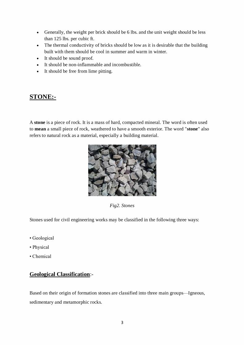
STONE:-
A stone is a piece of rock. It is a mass of hard, compacted mineral. The word is often used
to mean a small piece of rock, weathered to have a smooth exterior. The word "stone" also
refers to natural rock as a material, especially a building material.
Fig2. Stones
Stones used for civil engineering works may be classified in the following three ways:
• Geological
• Physical
• Chemical
Geological Classification:-
Based on their origin of formation stones are classified into three main groups—Igneous,
sedimentary and metamorphic rocks.
4
(i)Igneous Rocks:
These rocks are formed by cooling and solidifying of the rock masses from
their molten magmatic condition of the material of the earth. Generally igneous
rocks are strong and durable. Granite, trap and basalt are the rocks belonging to
this category, Granites are formed by slow cooling of the lava under thick cover on
the top. Hence they have crystalline surface. The cooling of lava at the top surface
of earth results into non-crystalline and glassy texture.
Example includes Trap and basalt.
(ii)Sedimentary Rocks:
Due to weathering action of water, wind and frost existing rocks
disintegrates. The disintegrated material is carried by wind and water; the water
being most powerful medium. Flowing water deposits its suspended materials at
some points of obstacles to its flow. These deposited layers of materials get
consolidated under pressure and by heat. Chemical agents also contribute
to the cementing of the deposits. The rocks thus formed are more uniform, fine
grained and compact in their nature. They represent a bedded or stratified structure
in general.
Example includes Sand stones, lime stones, mudstones etc.
(iii)Metamorphic Rocks:
Igneous and sedimentary rocks undergo changes due to metamorphic action of
pressure and internal heat. For example due to metamorphic action granite
becomes greisses, trap and basalt change to schist and laterite, lime stone changes
to marble, sand stone becomes quartzite and mud stone becomes slate.

5
Physical Classification:-
Based on the structure, the rocks may be classified as:
• Stratified rocks
• Unstratified rocks
(i)Stratified Rocks:
These rocks are having layered structure. They possess planes of stratification or
cleavage. They can be easily split along these planes. Sand stones, lime stones,
slate etc. are the examples of this class of stones.
(ii) Unstratified Rocks:
These rocks are not stratified. They possess crystalline and compact
grains. They cannot be split in to thin slab. Granite, trap, marble etc. are the
examples of this type of rocks.
(iii)Foliated Rocks:
These rocks have a tendency to split along a definite direction only. The direction
need not be parallel to each other as in case of stratified rocks. This type of
structure is very common in case of metamorphic rocks.
Chemical Classification:-
(a) Siliceous rocks: These rocks have silica (and, quartz and flint) as their principal
constituent and are very hard and durable, unaffected by weathering. Chief types of
siliceous rocks are Granites, Traps, Quartzite and Sandstones.
(b) Calcareous rocks: Calcium carbonate or lime is the main constituent of these
rocks. Crystalline and compact types are hard and durable. Clay is very often found
mixed in such rocks. Marbles and limestone are calcareous rocks.
6
(c) Argillaceous rocks: Rocks of the clayey types which are more or less composed
of alumina mixed with small quantities of other minerals. Slates and laterites belong
to this group.
Characteristics of Rocks:-
1. Colour
2. Streak
3. Hardness
4. Cleavage
5. Luster
Colour:
1. Some minerals have characteristics colour due to composition of the minerals and the
arrangement of the constituent atoms: for example black colour of magnetite, green of
chlorite and brassy yellow of pyrite
2. Minerals like quartz and calcite have variable colour
3. Colour can’t be sole identification property
Streak:
1. Colour of mineral in powder form is called streak
2. Powder is obtained by crushing the mineral.
3. Colour of the streak differs from colour of mineral: for example the colour of pyrite is
brass yellow and its streak is dark green.
Cleavage:
1. The cleavage of the minerals is its capacity to split more readily in certain directions
than in others, due to the arrangement of the atoms.
2. Minerals break with ease producing smooth surfaces is called perfect cleavage. It can
be good, distinct, indistinct and imperfect.
3. Some minerals such as mica have perfect cleavage in one direction. The feldspars,
which is the most abundant of all minerals, have two cleavages.
Luster:
1. Appearance of mineral in ordinary light (that is the appearance due to reflected light).
Luster may be metallic, glassy, earthy, pearly or silky
2. If the minerals looks metal as do galena and pyrite, its luster is said to be metallic. If
the minerals look glassy, like quartz, its luster is glassy.
Hardness:
1. The hardness of a mineral, as commonly determined on fresh material, is measured by
its ability to resist scratching. If a mineral is scratched by a knife, it is softer than the
7
knife. If it cannot be scratched by a knife, the two are equal hardness or the mineral is
the harder.
2. In order to have a standard method of expressing hardness of minerals, a simple scale,
known as the Mohr’s scale, has been universally adopted.
3. In sequence of increasing hardness from 1 to 10, the following minerals are used as
standard of comparison:
4. Talc, Gypsum, Calcite, Fluorite, Apatite, Orthoclase (feldspar), Quartz, Topaz,
Corundum and Diamond
CEMENT:-
Cement is a binder, a substance used for construction that sets, hardens, and adheres to
other materials to bind them together. Cement mixed with fine aggregate produces mortar for
masonry, or with sand and gravel, produces concrete. Concrete is the most widely used
material in existence and is only behind water as the planet's most-consumed resource.[1]
Cements used in construction are usually inorganic, often lime or calcium silicate based, and
can be characterized as either hydraulic or non-hydraulic, depending on the ability of the
cement to set in the presence of water (see hydraulic and non-hydraulic lime plaster).
TYPES OF CEMENT AND THEIR USES:-
1. Ordinary Portland Cement (OPC)
2. Portland Pozzolana Cement (PPC)
3. Rapid Hardening Cement
4. Quick setting cement
5. Low Heat Cement
6. Sulphates resisting cement
7. Blast Furnace Slag Cement
8. High Alumina Cement
9. White Cement
10. Coloured cement
11. Air Entraining Cement
12. Expansive cement
13. Hydro graphic cement

8
1. Ordinary Portland Cement (OPC):-
Ordinary Portland cement is the most widely used type of cement which is suitable for all
general concrete construction. It is most widely produced and used type of cement around the
world with annual global production of around 3.8 million cubic meters per year. This
cement is suitable for all type of concrete construction.
2. Portland Pozzolana Cement (PPC):-
Portland pozzolana cement is prepared by grinding pozzolanic clinker with Portland cement.
It is also produced by adding pozzolana with the addition of gypsum or calcium sulphate or
by intimately and uniformly blending Portland cement and fine pozzolana.
This cement has high resistance to various chemical attacks on concrete compared with
ordinary Portland cement and thus it is widely used. It is used in marine structures, sewage
works, sewage works and for laying concrete under water such as bridges, piers, dams and
mass concrete works etc.
3. Rapid Hardening Cement:-
Rapid hardening cement attains high strength in early days it is used in concrete where
formworks are removed at an early stage and is similar to ordinary portland cement (OPC).
This cement has increased lime content and contains higher c3s content and finer grinding
which gives greater strength development than OPC at an early stage.
The strength of rapid hardening cement at the 3 days is similar to 7 days strength of OPC
with the same water-cement ratio. Thus, advantage of this cement is that formwork can be
removed earlier which increases the rate of construction and decreases cost of construction by
saving formwork cost. Rapid hardening cement is used in prefabricated concrete
construction, road works, etc.
9
4. Quick setting cement:-
The difference between the quick setting cement and rapid hardening cement is that quick
setting cement sets earlier while rate of gain of strength is similar to Ordinary Portland
Cement, while rapid hardening cement gains strength quickly. Formworks in both cases can
be removed earlier.Quick setting cement is used where works is to be completed in very short
period and for concreting in static or running water.
5. Low Heat Cement:-
Low heat cement is prepared by maintaining the percentage of tricalcium aluminate below
6% by increasing the proportion of C2S. This makes the concrete to produce low heat of
hydration and thus is used in mass concrete construction like gravity dams, as the low heat of
hydration prevents the cracking of concrete due to heat.This cement has increased power
against sulphates and is less reactive and initial setting time is greater than OPC.
6. Sulphates Resisting Cement:-
Sulphate resisting cement is used to reduce the risk of sulphate attack on concrete and thus is
used in construction of foundations where soil has high sulphate content. This cement has
reduced contents of C3A and C4AF.Sulphate resisting cement is used in construction
exposed to severe sulphate action by water and soil in places like canals linings, culverts,
retaining walls, siphons etc.
7. Blast Furnace Slag Cement:-
Blast furnace slag cement is obtained by grinding the clinkers with about 60% slag and
resembles more or less in properties of Portland cement. It can be used for works economic
considerations are predominant.
8. High Alumina Cement:-

10
High alumina cement is obtained by melting mixture of bauxite and lime and grinding with
the clinker. It is a rapid hardening cement with initial and final setting time of about 3.5 and 5
hours respectively. The compressive strength of this cement is very high and more workable
than Ordinary Portland Cement and is used in works where concrete is subjected to high
temperatures, frost, and acidic action.
9. White Cement:-
It is prepared from raw materials free from Iron oxide and is a type of ordinary Portland
cement which is white in colour. It is costlier and is used for architectural purposes such as
precast curtain wall and facing panels, terrazzo surface etc. and for interior and exterior
decorative work like external renderings of buildings, facing slabs, floorings, ornamental
concrete products, paths of gardens, swimming pools etc.
10. Colored cement:-
It is produced by mixing 5- 10% mineral pigments with ordinary cement. They are widely
used for decorative works in floors.
11. Air Entraining Cement:-
Air entraining cement is produced by adding indigenous air entraining agents such as resins,
glues, sodium salts of sulphates etc. during the grinding of clinker. This type of cement is
especially suited to improve the workability with smaller water cement ratio and to improve
frost resistance of concrete.
12. Expansive Cement:-
Expansive cement expands slightly with time and does not shrink during and after the time of
hardening. This cement is mainly used for grouting anchor bolts and pre stressed concrete
ducts.
11
13. Hydro graphic cement:-
Hydro graphic cement is prepared by mixing water repelling chemicals and has high
workability and strength. It has the property of repelling water and is unaffected during
monsoon or rains. Hydrophobic cement is mainly used for the construction of water
structures such dams, water tanks, spillways, water retaining structures etc.
The following tests are conducted on cement in the laboratory are as follows:
Fineness Test.
Consistency Test.
Setting Time Test.
Strength Test.
Soundness Test.
Heat of Hydration Test.
Tensile Strength Test.
Chemical Composition Test.
USES:-
Cement is a very useful binding material in construction. The applications of cement over
various fields of construction have made it a very important civil engineering material.
Some of the numerous functions of cement are given below.
1. It is used in mortar for plastering, masonry work, pointing, etc.
2. It is used for making joints for drains and pipes.
3. It is used for water tightness of structure.
4. It is used in concrete for laying floors, roofs and constructing lintels, beams, stairs,
pillars etc.
5. It is used where a hard surface is required for the protection of exposed surfaces of
structures against the destructive agents of the weather and certain organic or
inorganic chemicals.
6. It is used for precast pipes manufacturing, piles, fencing posts etc.
7. It is used in the construction of important engineering structures such as bridges,
culverts, dams, tunnels, lighthouses etc.
8. It is used in the preparation of foundations, watertight floors, footpaths etc.
9. It is employed for the construction of wells, water tanks, tennis courts, lamp posts,
telephone cabins, roads etc.

12
CONCRETE:-
Concrete is a composite material composed of fine and coarse aggregate bonded together with a
fluid cement (cement paste) that hardens (cures) over time.
Quality of mixing water:-
The common specifications regarding quality of mixing water is water should be fit for
drinking. Such water should have inorganic solid less than 1000 ppm. This content lead to a solid
quantity 0.05% of mass of cement when w/c ratio is provided 0.5 resulting small effect on
strength.
WORKABILITY:-
Workability of concrete is the property of freshly mixed concrete which determines the ease and
homogeneity with which it can be mixed, placed, consolidated and finished.
COMPACTION OF CONCRETE:-
Compaction is the process which expels entrapped air from freshly placed concrete and packs
the aggregate particles together so as to increase the density of concrete. It increases significantly
the ultimate strength of concrete and enhances the bond with reinforcement.
CONCRETE MIX DESIGN:-
Mix design can be defined as the process of selecting suitable ingredients of concrete and
determining their relative proportions with the object of producing concrete of certain minimum
strength and durability as economically as possible.
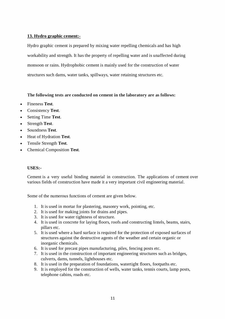
GRADES OF CONCRETE:-
Grade of concrete is the designation of concrete according to its compressive strength. Concrete
grades are denoted by M10, M20, M30 according to their compressive strength. The “M”
denotes Mix design of concrete followed by the compressive strength number in N/mm2
13
R.C.C.(Reinforced cement Concrete):-
R.C.C Full Form: RCC is a combination of concrete and steel to build a structure instead of using
only concrete. Concrete is good in resisting compression but is very weak in resisting tension.
PRESTRESSED CONCRETE:-
A pre-stressed concrete structure is different from a conventional reinforced concrete structure
due to the application of an initial load on the structure prior to its use.
Pre-stressed concrete is a combination of high strength concrete and steel strands. This
combination makes a very strong structural material that is used in the building of roof slabs,
bridge girders and railroad ties.
Pre-stressed concrete can be created using two different methods; pre-tension and post-tension.
The pretension method involves stretching high tensile steel strands between abutments located at
both ends of the concrete casting bed. After the strands are taught, concrete is poured into the
beds, where it surrounds and adheres to the strands. Once the concrete is dry it will have bonded
to the steel. After the concrete has reached the desired strength the strands are released, resulting
in the concrete developing a slight arch that makes it more resistant to heavy loads.
14
STEEL:-
Steel is an alloy of iron and carbon, and sometimes other elements like chromium. Because
of its high tensile strength and low cost, it is a major component used in buildings,
infrastructure, tools, ships, trains, automobiles, machines, appliances, and weapons. Iron is
the base metal of steel.
Plain Carbon Steel
Alloy Steel
Low Alloy Steel
Stainless Steel
Plain Carbon Steel:-
Plain carbon steel contains no appreciable alloying element other than carbon itself,
and, depending on the carbon content, is classified as low-, medium-, or high-carbon.
Low-carbon steel (< 0.3% C) is used for making rivets, cold-drawn parts such as wire,
stampings, etc. in the lower ranges and structural shapes, gears, cold-forged parts, and
welded tube in the middle and upper ranges.
Medium-carbon steel (0.3-0.5% C) is used for gears, shafts, connecting rods, seamless
tubing, etc. and is sometimes called machinery steel.
High-carbon steel (> 0.5% C) is used for springs, knives and hand tools, taps and
milling cutters, wire-drawing dies, etc. and is sometimes called tool or spring steel.
Alloy Steel:-
The carbon content of steel that determines the degree to which it can be hardened, certain
alloying elements added to the steel can make heat treatment less traumatic, a benefit when it
comes to reducing quenching distortion in complex, thin-walled parts, for example. The term
hardenability refers to how deep a steel can be hardened, and alloy steels loosely fall into two
camps around this measure: carburizing steel, which mostly hardens near the surface, and
through-hardening steel, which can extend the hardening down into the metal’s core.
Low Alloy Steel:-
Sometimes called HSLA, or High-Strength Low-Alloy, steel, this metal offers improved
strength over plain carbon steels and is used in settings where weight is a factor such as
mobile equipment. It cold-forms well and is readily welded. It has better resistance to
corrosion than plain steel, with good impact, fatigue, and abrasion resistance as well.
Other low alloy steels, with designations such as HY 80 and HY 90, are used for ship hulls
and off-highway equipment. Still, other low alloy steels are available for specific conditions
such as low-temperature toughness or to produce protective, weathering layers on decorative
steel used for building facades.
15
Stainless Steel:-
Stainless steel is an iron/chromium alloy that contains anywhere from 10 to 30%
chromium which gives the metal high resistance to corrosion.
Although there are many grades of stainless steel, only a dozen or so are used with
any regularity. For example, AISI Type 304 SS, having a chromium-nickel
constituent and low carbon, is popular for its good corrosion resistance, clean ability,
and formability, making it popular for many everyday items such as kitchen sinks.
AISI Type 316 SS, containing the alloying element molybdenum, is even more
resistant to chemical attack than Type 304, making it useful for exposure to seawater,
brine, sulphuric acids, and other corrosives found in the industrial environment
BUILDING COMPONENTS AND THEIR REQUIRMENTS:-
MORTAR:-
Mortar is a material used in masonry construction to fill the gaps between the bricks and
blocks used in construction. Mortar is a mixture of sand, a binder such as cement or lime, and
water and is applied as a paste which then sets hard.
Mortar is used to hold building materials such as brick or stone together. It is composed of a
thick mixture of water, sand, and cement. The water is used to hydrate the cement and hold
the mix together. The water to cement ratio is higher in mortar than in concrete in order to
form its bonding element.
STONE MASONRY:- Stone masonry is a type of building masonry construction that uses stones and mortar. This
construction technique is used for building foundations, floors, retaining walls, arches, walls
and columns. The stones used for masonry construction are natural rocks.
Types of Stone Masonry:-
Rubble masonry.
Types of Rubble Masonry. (i) Random Rubble Masonry. (ii) Coursed Rubble Masonry of
The First Sort. (iii) Coursed Rubble Masonry of The Second Sort.
Bond Stones in Rubble Work.
Ashlar Masonry.
Types of Ashlar Masonry.
Ashlar Facing With Backing of Brickwork (COMPOSITE MASONRY).
16
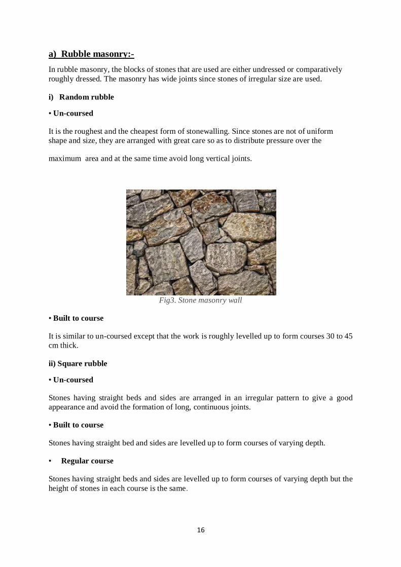
a) Rubble masonry:-
In rubble masonry, the blocks of stones that are used are either undressed or comparatively
roughly dressed. The masonry has wide joints since stones of irregular size are used.
i) Random rubble
• Un-coursed
It is the roughest and the cheapest form of stonewalling. Since stones are not of uniform
shape and size, they are arranged with great care so as to distribute pressure over the
maximum area and at the same time avoid long vertical joints.
Fig3. Stone masonry wall
• Built to course
It is similar to un-coursed except that the work is roughly levelled up to form courses 30 to 45
cm thick.
ii) Square rubble
• Un-coursed
Stones having straight beds and sides are arranged in an irregular pattern to give a good
appearance and avoid the formation of long, continuous joints.
• Built to course
Stones having straight bed and sides are levelled up to form courses of varying depth.
• Regular course
Stones having straight beds and sides are levelled up to form courses of varying depth but the
height of stones in each course is the same.

17
Fig4.Uncoursed and Built to course
Fig5. Uncoursed built on course regular coursed
iii) Miscellaneous type rubble
. Polygonal rubble masonry
In this type, stones are hammer finished on the face to an irregular polygonal shape.
If stones are roughly shaped to form rough fitting, such a work is called rough picked work.
If stones are carefully shaped to form close fitting such a work is called close-picked work.
Ashlar Masonry:-
In ashlar masonry, all the stones are cut and dressed, or worked, so they have the same shape, size and surface texture. When stone is first hewn out of a
quarry, which is really nothing more than a giant sold rock wall, it's rough and
random. Stoneworkers have to use chisels and other tools to refine the stone to a more finished appearance. The stone blocks used in ashlar masonry are very
different than random uncut stones, which are sometimes called rubble. In fact, ashlar masonry is sometimes referred to as 'dressed stone'.
18
Types of Ashlar Masonry
Ashlars fine or coarse ashlar masonry
Random coarse ashlars masonry
Rough tooled ashlar masonry
Rock or quarry faced ashlars masonry
Chamfered ashlars masonry
Block in coarse masonry
Ashlar facing
Brick Masonry:-
Brick masonry is a highly durable form of construction. It is built by placing bricks
in mortar in a systematic manner to construct solid mass that withstand exerted
loads. There are several types of bricks and number of mortars which can be used
to construct brick masonry.
Types of Brick Masonry:-
1. Brick Work in Mud
The mud is used to fill up various joints brick masonry work.
Thickness of the mortar joint is 12 mm.
it is the cheapest type of brick masonry
employed for construction of walls with maximum height of 4 m.
2. Brick Work in Cement:-
This type of brick masonry is construction by laying bricks in cement mortar rather
than mud which is used in brick work in mud. There are three major classes of brick
work in cement which are summarized in Table 1.

19
Fig. 6: Brick work in mud
Table 1 Different classes of brick work in cement and their descriptions
Classes Descriptions
First Class
1. Cement of lime mortar is used,
2. The surface and edges of bricks are sharp,
3. And the thickness of mortar joints doesn’t
exceed 10mm
Second Class
1. Ground moulded bricks are used,
2. Bricks are rough and shape is slightly
irregular,
3. The thickness of mortar joint is 12 mm.
Third Class
1. Bricks are not hard ,rough surface with
distorted shape,
2. Used for temporary structures,
3. Used in places where rainfall is not heavy.
20
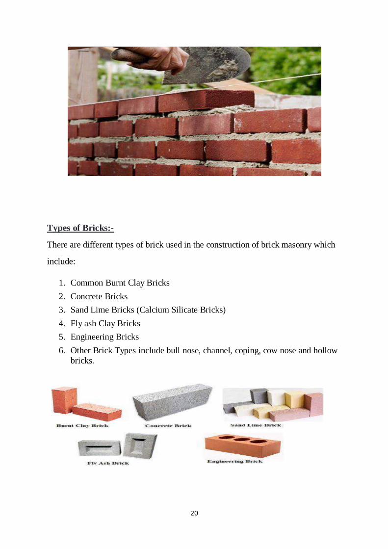
Types of Bricks:-
There are different types of brick used in the construction of brick masonry which
include:
1. Common Burnt Clay Bricks
2. Concrete Bricks
3. Sand Lime Bricks (Calcium Silicate Bricks)
4. Fly ash Clay Bricks
5. Engineering Bricks
6. Other Brick Types include bull nose, channel, coping, cow nose and hollow bricks.
21
ROOF:-
A roof is the top covering of a building, including all materials and constructions necessary
to support it on the walls of the building or on uprights; it provides protection against rain,
snow, sunlight, extremes of temperature, and wind. A roof is part of the building envelope.
TYPES:-
A-frame Roof:-
This type of roof is very popular for churches, cottages, homes, and other structures. The roof
acts as both the roof and the walls for a structure.
Butterfly Roof:-
The butterfly roof is not a roof style that is widely used. The style provides plenty of light and
ventilation as it provides options to have large windows due to the high perimeter windows. It
can be effective when it comes to water drainage as it can centralise the water flow however,
the cost to install and repair can be expensive due to the complexity in installing.
When done right this roof structure can add a modern look and feel to the property making it
a good choice to add a new dimension to a building for architects.
Flat Roof:-
Flat roofs are common especially with commercial buildings. Flat roofs are definitely the
most simple roof to build because they have little to no pitch. The most common types of
roofing systems used with flat roofs are rubber roofing systems.
Folded Plate Roof:-
The folded plate roof has limited use in single family homes. It looks like a series of small
gable roofs placed side by side of each other.
Gable Roof:-
Gable roofs are the kind young children typically draw. They have two sloping sides that
come together at a ridge, creating end walls with a triangular extension, called a gable, at the
top. The house shown here has two gable roofs and two dormers, each with gable roofs of
their own. The slant, or pitch, of the gables varies, an inconsistency that many builders try to
avoid.
It is one of the most common roof structures around and one of the least expensive to build. It
allows water to drain off easily making it a desirable structure for environments with heavy
down pour. However, damage may occur in places that do have heavy wind.
Gambrel Roof:
Gambrel roofs are a type of gabled roof. Commonly associated with Dutch building traditions
and barns, they break each sloping roof section into two parts—one close to the ridge that is
relatively flat and one closer to the eaves that drops down steeply. This design makes
maximum use of space under the roof.
The best way to describe a gambrel roof is by saying barn roof. The gambrel style roof is
most commonly used on barns. However, it is also used in residential construction. This type
of roof has the benefit of providing a good amount of space in the attic. In fact, it provides so
much extra space that it is often turned into bedrooms or other living areas.

22
Hip Roof: Hip roofs are a common residential style roofs. This type of roof is more difficult to construct
when compared to flat roofs and gable roofs because they have a more complicated truss and
rafter structure. A hip roof has four sloping sides with zero vertical roof lines/walls. Hip roofs
can be both square and rectangular but most commonly seen with two sides that are longer
than the other two sides.
Due to its pyramid structure the hip roof if very stable and incredibly strong providing very
little need for extra support.
Mansard Roof: The mansard roof is a French design and is more difficult to construct than the hip or gable
roof.
A Mansard roof is similar to a Gambrel roof in that each side of the roof has multiple
gradients, however Gambrel roofs have just 2 sides while a Mansard roof has 4. Typically,
dormer windows are installed on the lower, steeper slopes of the Mansard roof to aid the
roof’s architecture and open up the space to become habitable.
M-Shaped Roof / Double Pitched Roof:
Double-pitched roof is a traditional, most often used roof. It is the most popular roof type.
Generally, we can describe the double pitched roof as a triangle that consists of two surfaces
which are connected with ridge on the top.
Parapet Roof:
A parapet is a barrier which is an extension of the wall at the edge of
a roof, terrace, balcony, walkway or other structure. Where extending above a roof, a parapet
may simply be the portion of an exterior wall that continues above the line of the roof
surface, or may be a continuation of a vertical feature beneath the roof such as a fire
wall or party wall. Parapets were originally used to defend buildings from military attack, but
today they are primarily used as guard rails and to prevent the spread of fires.
Pyramid Hip Roof: The Dutch hip roof is basically a hip roof with a small gable at either end. The gables can be
used as ventilation. Pyramid Hip Roofs are commonly used for smaller buildings such as
bungalows, cabins and garages and are an ideal roof structure for places where the weather is
a little wet.
Saltbox Roof:
A saltbox house is a traditional New England style of house with a long, pitched roof that
slopes down to the back, generally a wooden frame house. A saltbox has just one story in the
back and two stories in the front. The flat front and central chimney are recognisable features,
but the asymmetry of the unequal sides and the long, low rear roof line are the most
distinctive features of a saltbox, which takes its name from its resemblance to a wooden
lidded box in which salt was once kept.
It is very similar to a gable roof however, the main differentiating factor is that the salt box is
asymmetry while the gable design has symmetrical slopes on either side.
There are many pros to a saltbox such as; it’s drainage capabilities, ease of access due to its
low edges, eye catching design and ease of adding roof windows.
It does come with some cons however, starting with its complexity to build and the limited
space it can bring to the attic. Not to mention the sloping ceilings to the rooms.

23
If you are looking to create more living space in the property, maybe this isn’t the ideal roof
to use.
Shed Roof:
A shed roof is basically a flat roof but has more pitch. It is frequently used for additions on
homes or other roof styles.
Winged Gable Roof:
The winged gable roof varies slightly from the tradition gable roof. It varies by extended
outwards from the peak of the roof.
Roof Pitch
The pitch or slope of a roof is a critical deciding factor in many of the roofing decisions.
Depending on the pitch/slope of a roof, certain materials can or cannot be used. Pitch not only
helps determine what type of materials can or cannot be used but it also plays a major role in
attic space, drainage options, weather durability, design, and difficulty of construction and
maintenance.
The slope of a roof is split up into three categories.
1. Flat Roof: (Anything under a 2:12 pitch)
2. Low Slope: (A 4:12 pitch to a 2:12 pitch)
3. Steep Slope: (A 4:12 pitch to a 21:12 pitch)
Roof Material
Asphalt Shingles:
Asphalt shingles are the most commonly used steep slope/residential roofing material used on
roofs in the United States. Asphalt shingles vary in quality and are produced by multiple
manufacturers.
Wood Shake:
The shake shingle is the inspiration for the modern day asphalt shingles. Similar to the
asphalt shingle, the wood shake overlaps each other making the roof or siding weather proof.
A down side to shake is that they often need more maintenance than newer asphalt or
fiberglass shingles. An upside to shake the unique rustic look they give to a structure.
Slate Shingles:
These are shingles made out of rock. Slate shingles are created out of a sedimentary rock.
This rock can be split into thin sheets that are ideal for roofing shingles.
Metal:
Metal is a very common material used for roofs. There are many different types of metal
roofing systems available. The types of metal used with available systems varies from zinc to
steel, copper, aluminium, and tin.
24
Tile:
Tile is one of the more expensive materials used for roofs. Although the traditional clay tile is
probably the most well known tile material it is not the only one. Other materials that are
used to create tile products are metal, concrete, slate, and various synthetic compositions.
Membrane Roofing Material:
There are many different types of products included in this category for roofing and in fact
that number continues to grow with the technological advancements and findings. Membrane
roofing products are used on flat roofs. Some of the various brands or variations of rubber
roofs are modified bitumen, thermoplastic membrane, EPDM, single ply, TPO, CPA, CPE,
NBP, and others.
FLOOR:-
A floor is the bottom surface of a room or vehicle. Floors vary from simple dirt in a cave to
many-layered surfaces made with modern technology.
TYPES OF FLOORING:-
1. Carpet flooring – What is carpet flooring? Well, carpet flooring is laid wall to wall in a
room or hallway. This flooring option is losing its popularity with every passing day with
better, versatile and affordable options becoming available. But one thing that cannot be
denied is that carpet flooring adds charm to the house and is a good fit in bedrooms. The
house looks cosy, comfortable, and inviting with carpet flooring installed.
Some of the designs and qualities of carpet flooring are cheaper than wood or ceramic
flooring. It is known to trap dust, stain, and odour which might result in allergies and other
diseases. Loop pile, cut loop pile, level loop pile, Saxony, twist, frieze, and velvet are some
of the types of carpet flooring.
2. Tile flooring – Another option you can choose is tile flooring. Tiles come in a large
variety, variation, and styles. Any design can be embossed on tiles. You can add a fresh and
rather improved look to your home.
Tile flooring enhances the resale value of a home in the long run. But one thing that
homeowners need to know is that tile floor is not a good insulator of heat, and therefore the
flooring will be cold during the winter. It is rather difficult for the do-it-yourselfer because
the installation requires special tools. However, tile flooring is always a good option because
of the durability and the versatility it offers.
25
3.Laminate flooring – These flooring options can imitate many other flooring options like
marble, ceramic or hardwood flooring and that is why it is the best choice for the people who
are not willing to spend the money which is needed to install ceramic, marble, or hardwood
flooring. Laminate flooring is versatile and dynamic, can be installed quickly and has a long
lifespan which increases the value of homes.
However, almost anyone can differentiate between real hardwood flooring and laminate
flooring; therefore not everyone prefers it over hardwood flooring.
4. Hardwood flooring – People prefer hardwood flooring because it looks beautiful and
enhances the resale value of any home. Hardwood flooring can be anything from a rustic to a
modern look. There is nothing that can beat the look and the feel of hardwood flooring. It
provides warmth and a cozy feel in homes and what can be better than installing something
from nature itself.
However, that one thing which might be bothersome is the cost of hardwood flooring.
Hardwood flooring costs a lot of money, but the good news is that hardwood can be
refinished multiple times to make it look brand new.
5. Marble flooring – One of the most prestigious floors out there is marble flooring. In older
times, these floorings were only installed in royal palaces and churches. They are a bit more
expensive than other flooring options, but the look they add to any place they are installed at
is incomparable. This is a natural stone directly extracted from quarries. And being made of
natural stone, they allow water to seep into the floor. But that is an advantage in itself, and
natural stone is unique and translucent. Your house will glow and possess a unique look.
However, keep in mind that marble is a soft stone and is prone to scratches, cracks and other
damage so make sure to buy some extra slabs so that the floor could be replaced later on with
the same textured marble slabs.
6. Vinyl flooring – Some of the best things about vinyl flooring is that they are colourful,
versatile, easy to install, good for noise reduction, water resistant, slip resistant and
affordable.
Vinyl flooring comes in tiles and sheets. One thing that homeowners need to keep in mind is
that only good quality vinyl flooring is durable, stain resistant and scratch resistant.
Therefore, always go for the best quality of vinyl flooring.
26
MODULE II
SURVEYING
Linear Measurements:-
The determination of the distance between two points on the surface of the earth is one
of the basic operations of surveying. Measurement of horizontal distances or measuring
linear measurement is required in chain surveying, traverse surveying and other types
of surveying.
The following instruments are used while chaining:
Chains
Tapes
Arrows
Ranging rods and offset rods
Pegs
Plumb-bob
CHAIN:-
The chain is composed of 100 or 150 pieces of galvanized mild steel wire called links,
joined together with oval rings and handles at both ends.
The end of each link are bent into a loop and connected together by means of three
oval rings.
The ends of the chain are provided with brass handles for easy handling. The length of
chain is measured from one handle to other handle.
ARROWS OR CHAIN PINS:-
They are also called as marking or chaining pins and are used to mark the end of chain during
the process of chaining. They are made up of good quality hardened and tempered steel wire
of 4mm in diameter. The arrows are made 400 mm in length. The one pointed part of an
arrow is inserted into ground and the other is attached with ring.
RANGING RODS OR OFFSET RODS OR RANGING POLES:-
Ranging rods or offset rods are round poles made up of wood or metal.
These rods are used to range intermediate points of a survey and to set out straight
lines on the field when the surveying length is long.
The only difference between ranging rods and poles is the length. Ranging rods and
offset rods are commonly occurs in 3m length but the ranging poles are available up
to 8m length.
The rods possess a metal point at its bottom and the rod or pole is painted with red &
white or black & white successive combination.
When the survey lines are too lengthy a flag with red/white/yellow colour will be
attached to the top of the pole for easy identification.
27
PEGS:- The pegs are made up with wood and they used to mark the survey positions or
terminals.
The size of the pegs (40 to 60 cm) depends on the type of survey work they are used
for and the type of soil they have to be driven in. Although the pegs are driven into
the ground 1/5 th of its part should be visible on the ground surface.
PLUMB-BOB:-
A string suspended with a weight at the bottom will be both vertical and perpendicular to any
level plane through which it passes. The plumb consists of a specially designed weight and
coarse string or special threads. At one end of the string the weight is affixed. Precisely
machined and balanced bobs have pointed tips, and can be made of brass, steel, or other
materials, including plastic.
TAPES:-
Tapes are used for more accurate measurements. The tapes are classified based on the
materials of which they are made of such as:
Cloth or linen tape
Fibre tape
Metallic tape
Steel tape
Invar tape
RANGING:-
The process of establishing or developing intermediate points between two terminal points or
end points on a straight line is known as ranging.
Ranging is of two types
Direct Ranging:-
The ranging in which intermediate ranging rods are placed in a straight line by direct
observation from either end.
Direct ranging is possible only when the end stations are inter visible.
Indirect Ranging:-
The ranging in which intermediate points are interpolated by reciprocal ranging or running an
auxiliary line.
Indirect ranging is done where end points are not visible and the ground is high.
28
Compass Surveying
Compass surveying is a type of surveying in which the directions of surveying lines are
determined with a magnetic compass, and the length of the surveying lines are measured with
a tape or chain or laser range finder. The compass is generally used to run a traverse line.
PRISMATIC COMPASS:-
A prismatic compass is a navigation and surveying instrument which is extensively used to
find out the bearing of the traversing and included angles between them, waypoints (an
endpoint of the course) and direction.
Compass surveying is a type of surveying in which the directions of surveying lines are
determined with a magnetic compass, and the length of the surveying lines are measured with
a tape or chain or laser range finder.
The compass is generally used to run a traverse line. The compass calculates bearings of
lines with respect to magnetic needle.
The included angles can then be calculated using suitable formulas in case of clockwise and
anti-clockwise traverse respectively. For each survey line in the traverse, surveyors take two
bearings that is fore bearing and back bearing which should exactly differ by 180° if local
attraction is negligible.
The name Prismatic compass is given to it because it essentially consists of a prism which is
used for taking observations more accurately.
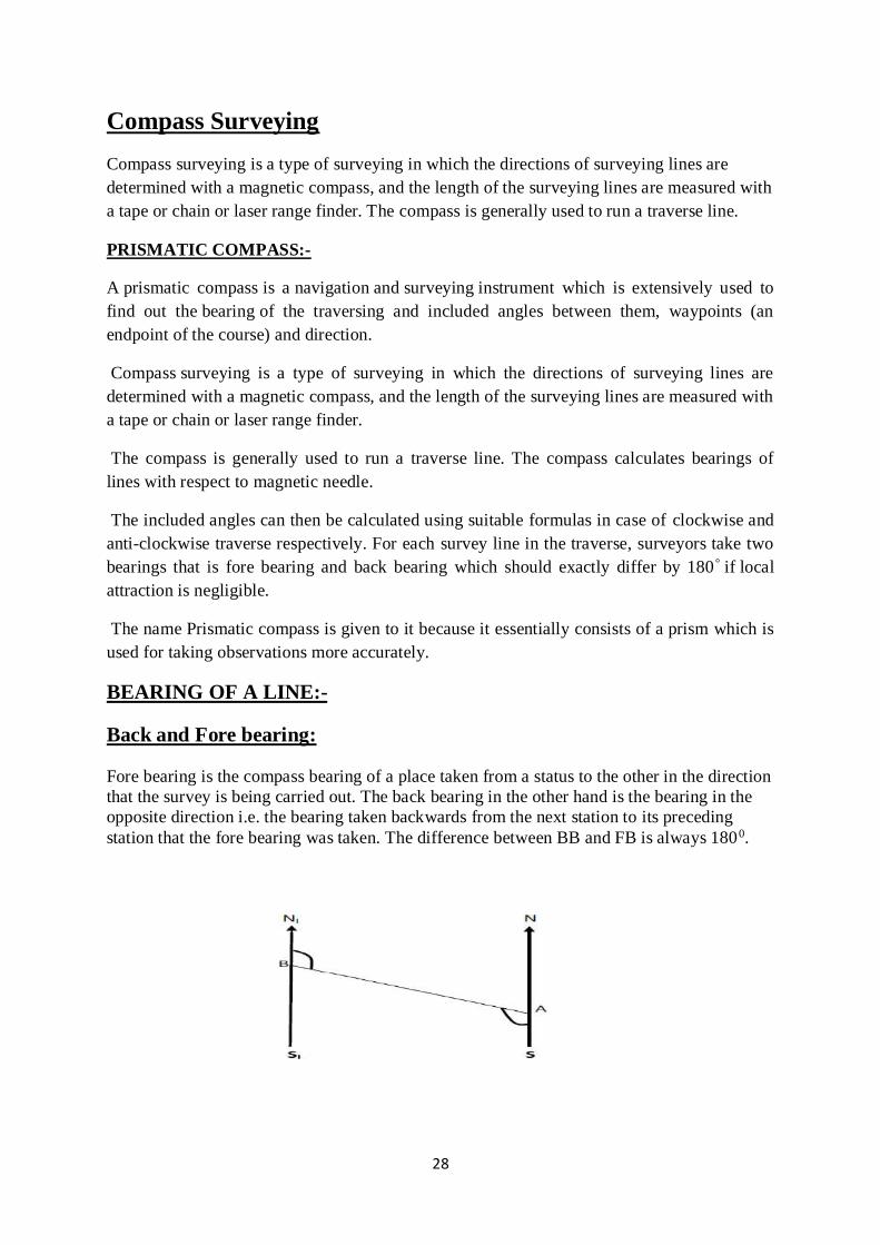
BEARING OF A LINE:-
Back and Fore bearing:
Fore bearing is the compass bearing of a place taken from a status to the other in the direction
that the survey is being carried out. The back bearing in the other hand is the bearing in the
opposite direction i.e. the bearing taken backwards from the next station to its preceding
station that the fore bearing was taken. The difference between BB and FB is always 1800.

29
Back and fore bearing
If B is sighted from an observer at A, and the NS and N1S1 are the magnetic NS lines, then
Forward bearing (FB) = < N A S + < S A B
Back bearing BA = < N1 B A
:. Back Bearing BA = Forward Bearing AB – 1800
If the observer relocates to B and observers B, then forward bearing (FB) BA = < N1 BA and
back bearing (AB) = < NAS + SAB. Hence, we can conclude that Forward Bearing = < N1 B
A + 1800. As a general rule, if the Fore Bearing is less than 1800, add 1800 to get the Back.
Bearing, and if the Fore Bearing is greater than 1800, then subtract 1800 to get the Back
Bearing.
Traversing and plotting with the compass survey:-
Traversing with the compass involves taking the bearing along a series of connecting straight
lines and in the same time measuring the distances with the tape. The compass is read at each
point and a back bearing is equally taken to serve as a check. This continues until the traverse
closes.
Choosing a suitable scale, the traverse is then plotted taking into consideration the general
shape of the area.
Observing Bearing of Line
Consider a line AB of which the magnetic bearing is to be taken.
By fixing the ranging rod at station B we get the magnetic bearing of needle wrt
north pole.
The enlarged portion gives actual pattern of graduations marked on ring.
Designation of bearing
The bearing is designated in the following two system:-
Whole Circle Bearing System.(W.C.B)
Quadrantal Bearing
System.(Q.B)
Whole circle bearing system
(W.C.B.):-
The bearing of a line measured with respect to magnetic meridian in
clockwise direction is called magnetic bearing and its value varies
between 0ᴼ to 360ᴼ.
The quadrant start from north and progress in a clockwise direction as the
first quadrant is 0ᴼ to 90ᴼ in clockwise direction , 2nd 90ᴼ to 180ᴼ , 3rd
180ᴼ to 270ᴼ, and up to 360ᴼ is 4th one.
Quadrantal bearing system(Q.B.):-
In this system, the bearing of survey lines are measured wrt to north line or south
line whichever is the nearest to the given survey line and either in clockwise
direction or in anti clockwise direction.

30
Reduced bearing (R.B):-
When the whole circle bearing is converted into Quadrantal bearing, it
is termed as “reduced bearing”.
Thus , the reduced bearing is similar to the Quadrantal bearing.
Its values lies between 0ᴼ to 90ᴼ, but the quadrant should be mentioned
for proper designation.
The following table should be remembered for conversion of WCB to RB.
W.C.B. of any line Quadrant in which it lies Rules for its conversion Quadrant
0 to 90 I RB=WCB N-E
90 to 180 II RB=180-WCB S-E
180 to 270 III RB=WCB-180 S-W
270 to 360 IV RB=360-WCB N-W
Error in compass survey (Local attraction & observational error):
Local attraction is the influence that prevents magnetic needle pointing to magnetic north pole
Unavoidable substances that affect are
Magnetic ore
Underground iron pipes
High voltage transmission line
Electric pole etc.
Detection of Local attraction
By observing the both bearings of line (F.B. & B.B.) and noting
the difference (1800 in case of W.C.B. & equal magnitude in
case of R.B.)
We confirm the local attraction only if the difference is not due
to observational errors.
If detected, that has to be eliminated.
Two methods of elimination
First method
Seco
nd method First
method
Difference of B.B. & F.B. of each lines of traverse is checked
31
to note if they differ by correctly or not.
The one having correct difference means that bearing measured
in those stations are free from local attraction
Correction is accordingly applied to rest of station.
If none of the lines have correct difference between F.B. &
B.B., the one with minimum error is balanced and repeat the
similar procedure.
Diagram is good friend again to solve the numerical problem.
Second method
Based on the fact that the interior angle measured on the
affected station is right.
All the interior angles are measured
Check of interior angle – sum of interior angles = (2n-4) x right
angle, where n is number of traverse side
Errors are distributed and bearing of lines are calculated with
the corrected angles from the lines with unaffected station.
Checks in closed Traverse
Errors in traverse is contributed by both angle and distance measurement
Checks are available for angle measurement but
There is no check for distance measurement
For precise survey, distance is measured twice, reverse
direction second time
Checks for angular error are available
Interior angle, sum of interior angles = (2n-4) x right angle,
where n is number of traverse side
Exterior angle, sum of exterior angles = (2n+4) x right angle,
where n is number of traverse side
Deflection angle – algebraic sum of the deflection angle should
be 00 or 3600.
Bearing – The fore bearing of the last line should be equal to its
back bearing ± 1800 measured at the initial station.
Checks in open traverse
No direct check of angular measurement is available
32
Indirect checks
Measure the bearing of line AD from A and bearing of
DA from D
Take the bearing to prominent points P & Q from
consecutive station and check in plotting.
MODERN SURVEYING INSTRUMENT:-
EDM:-
EDM stands for Electronic Distance Measurement. EDM is a surveying
instrument for measuring distance electronically between two points through
electromagnetic waves. The distance measured by EDM is more precise than
measured with chain or tape. The wave emitted from the EDM reaches the
reflector and return back to the EDM. Then the distance is measured with the
help of time taken for the above process – time taken by the wave for the
emission and return. Then the following equation used to measure the distance,
Distance= Velocity X time.
Electronic distance measuring instrument is a surveying instrument for
measuring distance electronically between two points through electromagnetic
waves.
Electronic distance measurement (EDM) is a method of determining the length
between two points, using phase changes, that occur as electromagnetic energy
waves travels from one end of the line to the other end.
TOTAL STATION:-
A total station is an electronic/optical instrument used in modern surveying and building
construction. The total station is an electronic theodolite (transit) integrated with an electronic
distance meter (EDM) to read slope distances from the instrument to a particular point and
software running on an external computer known as a data collector. With the aid of
trigonometry, the angles and distances may be used to calculate the actual positions (x, y, and
z or northing, easting and elevation) of surveyed points in absolute terms. – Beginning in
about 1980, an EDM component, which also had been improved to enable automatic readout,
was combined with an electronic theodolite to create a single instrument called the total
station. – The functions of the distance and angle measuring components were controlled by
an interfaced computer. – Modern total station instruments can now make slope distance
measurements, automatically display the results, and also store the data in the computer
memory. – They can also measure angles both in horizontal planes and vertical planes, and
again the results can be automatically displayed and stored. – The on-board computer can use
these measured data in real time to resolve horizontal and vertical distances, to calculate the
positions and elevations of points, or to set points for construction projects. – Total station
instruments are probably the most commonly used and important instruments in modern
surveying today, having practically replaced all transits, theodolites, and stand alone EDM
instruments. – With a total station one may determine angles and distances from the

33
instrument to points to be surveyed. With the aid of trigonometry and triangulation, the
angles and distances may be used to calculate the coordinates of actual positions (X, Y, and Z
or northing, easting and elevation) of surveyed points, or the position of the instrument from
known points, in absolute terms. – The data may be downloaded from the theodolite to an
external computer and application software will generate a map of the surveyed area.
Field Procedure for Total Station in Topographic Surveying
1. Prior to Physical Setup of the Total Station
2. Tripod Setup
3. Mounting the Total Station
4. Setting up (Levelling) the Total Station a) Centring b) Levelling c) Focusing
5. Setting up Prism over the Station
6. Powering Up the Total Station
7. Powering Up the Palmtop Computer
8. Communication Techniques
9. Coding Specific Points
10. Data Downloading, Manipulation and Software
11. Preparation of Maps
Advantages using total station:-
Field work is carried out very fast.
2. Accuracy of measurement is high.
3. Manual errors involved in reading and recording are eliminated.
4. Calculation of coordinates is very fast and accurate. Even corrections for
temperature and pressure are automatically made.
5. Computers can be employed for map making and plotting contour and cross-sections.
Contour intervals and scales can be changed in no time.
34
MODULE III
SOILS AND ITS CLASSIFICATION:-
Soils are complex mixtures of minerals, water, air, organic matter, and countless organisms
that are the decaying remains of once-living things.
Engineers, typically geotechnical engineers, classify soils according to their engineering
properties as they relate to use for foundation support or building material. Modern
engineering classification systems are designed to allow an easy transition from field
observations to basic predictions of soil engineering properties and behaviours.
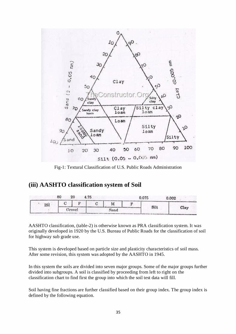
The classification of soil exclusively based on particle size and their percentage distribution
is known as textural classification system. This system specifically names the soil depending
on the percentage of sand, silt and clay. The triangular charts are used to classify soil by this
system.
Soil may be broadly classified as follows:
1. Classification based on grain size
2. Textural classification
3. AASHTO classification system
4. Unified soil classification system
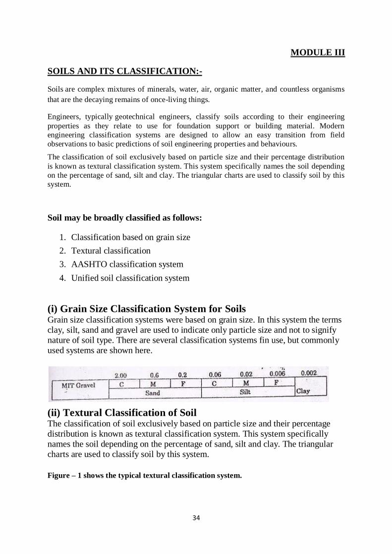
(i) Grain Size Classification System for Soils Grain size classification systems were based on grain size. In this system the terms clay, silt, sand and gravel are used to indicate only particle size and not to signify nature of soil type. There are several classification systems fin use, but commonly used systems are shown here.
(ii) Textural Classification of Soil The classification of soil exclusively based on particle size and their percentage distribution is known as textural classification system. This system specifically names the soil depending on the percentage of sand, silt and clay. The triangular charts are used to classify soil by this system.
Figure – 1 shows the typical textural classification system.
35
Fig-1: Textural Classification of U.S. Public Roads Administration
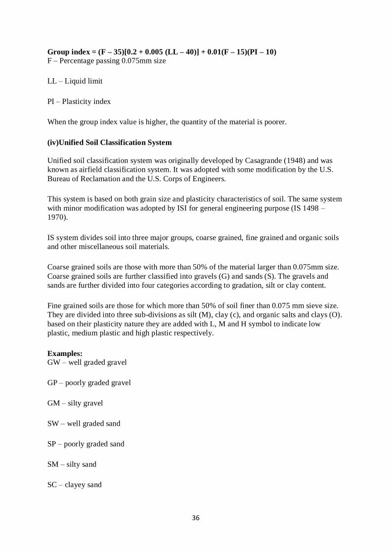
(iii) AASHTO classification system of Soil
AASHTO classification, (table-2) is otherwise known as PRA classification system. It was
originally developed in 1920 by the U.S. Bureau of Public Roads for the classification of soil
for highway sub grade use.
This system is developed based on particle size and plasticity characteristics of soil mass.
After some revision, this system was adopted by the AASHTO in 1945.
In this system the soils are divided into seven major groups. Some of the major groups further
divided into subgroups. A soil is classified by proceeding from left to right on the
classification chart to find first the group into which the soil test data will fill.
Soil having fine fractions are further classified based on their group index. The group index is
defined by the following equation.
36
Group index = (F – 35)[0.2 + 0.005 (LL – 40)] + 0.01(F – 15)(PI – 10) F – Percentage passing 0.075mm size
LL – Liquid limit
PI – Plasticity index
When the group index value is higher, the quantity of the material is poorer.
(iv)Unified Soil Classification System
Unified soil classification system was originally developed by Casagrande (1948) and was
known as airfield classification system. It was adopted with some modification by the U.S.
Bureau of Reclamation and the U.S. Corps of Engineers.
This system is based on both grain size and plasticity characteristics of soil. The same system
with minor modification was adopted by ISI for general engineering purpose (IS 1498 –
1970).
IS system divides soil into three major groups, coarse grained, fine grained and organic soils
and other miscellaneous soil materials.
Coarse grained soils are those with more than 50% of the material larger than 0.075mm size.
Coarse grained soils are further classified into gravels (G) and sands (S). The gravels and
sands are further divided into four categories according to gradation, silt or clay content.
Fine grained soils are those for which more than 50% of soil finer than 0.075 mm sieve size.
They are divided into three sub-divisions as silt (M), clay (c), and organic salts and clays (O).
based on their plasticity nature they are added with L, M and H symbol to indicate low
plastic, medium plastic and high plastic respectively.
Examples: GW – well graded gravel
GP – poorly graded gravel
GM – silty gravel
SW – well graded sand
SP – poorly graded sand
SM – silty sand
SC – clayey sand

37
CL – clay of low plastic
CI – clay of medium plastic
CH – clay of higher plastic
ML – silt of medium plastic
MI – silt of medium plastic
MH – silt of higher plastic
OL – organic silt and clays of low plastic
OI – organic silt and clays of medium plastic
OH – organic silt and clays of high plastic.
FOUNDATIONS:-
Foundation is the lowermost structure in any building, it will transfer the load from
superstructure to the soil (substructure).There would have been no need of foundation if the
soil is good in shear. The column would have been sufficient.
It is of 2 types.
Shallow foundation
Deep foundation
The different types of shallow foundation are:
1. Strip footing
2. Spread or isolated footing
3. Combined footing Strap or cantilever footing
4. Mat or raft Foundation

38
1. Strip Footing:-
A strip footing is provided for a load-bearing wall. A strip footing is also provided for a row
of columns which are so closely spaced that their spread footings overlap or nearly touch
each other. In such a case, it is more economical to provide a strip footing than to provide a
number of spread footings in one line. A strip footing is also known as continuous footing.
2. Spread or Isolated Footing or Individual Footing:-
A spread footing also called as isolated footing, pad footing and individual footing is
provided to support an individual column. A spread footing is circular, square or rectangular
slab of uniform thickness. Sometimes, it is stepped or hunched to spread the load over a large
area.

39
3. Combined Footing:-
A combined footing supports two columns. It is used when the two columns are so close to
each other that their individual footings would overlap. A combined footing is also provided
when the property line is so close to one column that a spread footing would be eccentrically
loaded when kept entirely within the property line. By combining it with that of an interior
column, the load is evenly distributed. A combined footing may be rectangular or trapezoidal
in plan.
4. Strap or Cantilever Footing:-
A strap (or cantilever) footing consists of two isolated footings connected with a structural
strap or a lever. The strap connects the two footings such that they behave as one unit. The
strap is designed as a rigid beam. The individual footings are so designed that their combined
line of action passes through the resultant of the total load. a strap footing is more economical
than a combined footing when the allowable soil pressure is relatively high and the distance
between the columns is large.
40
5. Mat or Raft Foundations:-
A mat or raft foundation is a large slab supporting a number of columns and walls under the
entire structure or a large part of the structure. A mat is required when the allowable soil
pressure is low or where the columns and walls are so close that individual footings would
overlap or nearly touch each other.
Mat foundations are useful in reducing the differential settlements on non-homogeneous soils
or where there is a large variation in the loads on individual columns.
DEEP FOUNDATION:-
A deep foundation is a type of foundation that transfers building loads to the earth farther
down from the surface than a shallow foundation does to a subsurface layer or a range of
depths.
Deep foundation is required to carry loads from a structure through weak compressible soils
or fills on to stronger and less compressible soils or rocks at depth, or for functional reasons.
Deep foundations are founded too deeply below the finished ground surface for their base
bearing capacity to be affected by surface conditions, this is usually at depths >3 m below
finished ground level.
Deep foundation can be used to transfer the loading to deeper, more competent strata at depth
if unsuitable soils are present near the surface.
Types of Deep Foundation:-
The types of deep foundations in general use are as follows:
1. Basements
2. Buoyancy rafts (hollow box foundations)
3. Caissons
4. Cylinders
5. Shaft foundations
6. Pile foundations
1. Basement foundation:-
These are hollow substructures designed to provide working or storage space below ground
level. The structural design is governed by their functional requirements rather than from
considerations of the most efficient method of resisting external earth and hydrostatic
pressures. They are constructed in place in open excavations.

41
2. Buoyancy Rafts (Hollow Box Foundations):-
Buoyancy rafts are hollow substructures designed to provide a buoyant or semi-buoyant
substructure beneath which the net loading on the soil is reduced to the desired low intensity.
Buoyancy rafts can be designed to be sunk as caissons; they can also be constructed in place
in open excavations.
3. Caissons Foundations:-
Caissons are hollow substructures designed to be constructed on or near the surface and then
sunk as a single unit to their required level.
4. Cylinders:-
Cylinders are small single-cell caissons.
5. Drilled Shaft foundations:-
Shaft foundations are constructed within deep excavations supported by lining constructed in
place and subsequently filled with concrete or other pre-fabricated load-bearing units.
6. Pile foundations:-
Pile foundations are relatively long and slender members constructed by driving
preformed units to the desired founding level, or by driving or drilling-in tubes to the required
depth – the tubes being filled with concrete before or during withdrawal or by drilling unlined
or wholly or partly lined boreholes which are then filled with concrete.
42
IRRIGATION ENGINEERING
Irrigation engineering is a kind of civil engineering which includes the study of controlling
and harnessing the various natural sources of water.
It studies the irrigation and agriculture in-depth. Flooding is the basis of agriculture and the
only way by which water is supplied to the crops.
Irrigation engineering is a field of engineering which would discuss the uses of irrigation in
crop production and how new principles and technologies can be used and applied for
irrigational practices.
It is essential to study irrigation engineering as it helps in determining future irrigation
expectations and impacts of irrigation in the agriculture field.
A hydraulic structure is a structure submerged or partially submerged in any body of
water, which disrupts the natural flow of water. They can be used to divert, disrupt or
completely stop the flow.
Example includes
Canal
Siphon
Weir
Dam
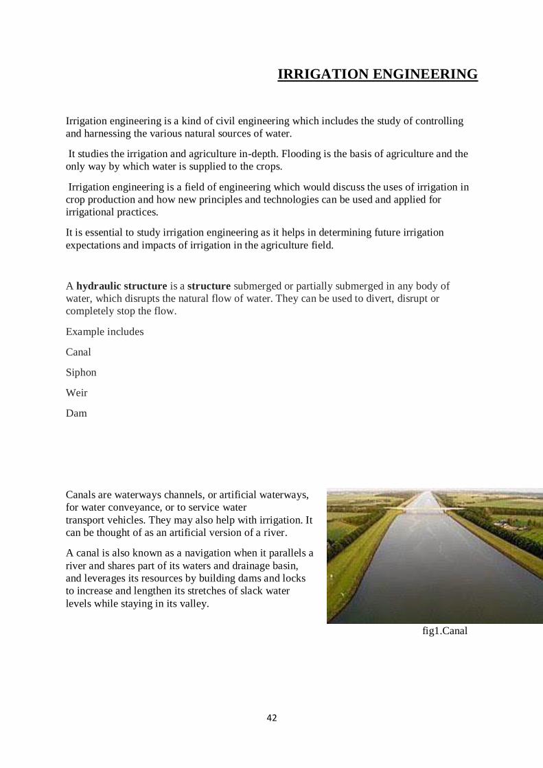
Canals are waterways channels, or artificial waterways,
for water conveyance, or to service water
transport vehicles. They may also help with irrigation. It
can be thought of as an artificial version of a river.
A canal is also known as a navigation when it parallels a
river and shares part of its waters and drainage basin,
and leverages its resources by building dams and locks
to increase and lengthen its stretches of slack water
levels while staying in its valley.
fig1.Canal
43
A siphon spillway is a type of spillway in which surplus water is disposed to downstream
through an inverted U shaped conduit. It is generally arranged inside the body or over the
crest of the dam.
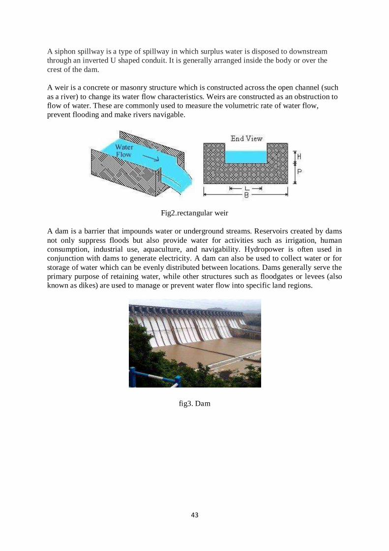
A weir is a concrete or masonry structure which is constructed across the open channel (such
as a river) to change its water flow characteristics. Weirs are constructed as an obstruction to
flow of water. These are commonly used to measure the volumetric rate of water flow,
prevent flooding and make rivers navigable.
Fig2.rectangular weir
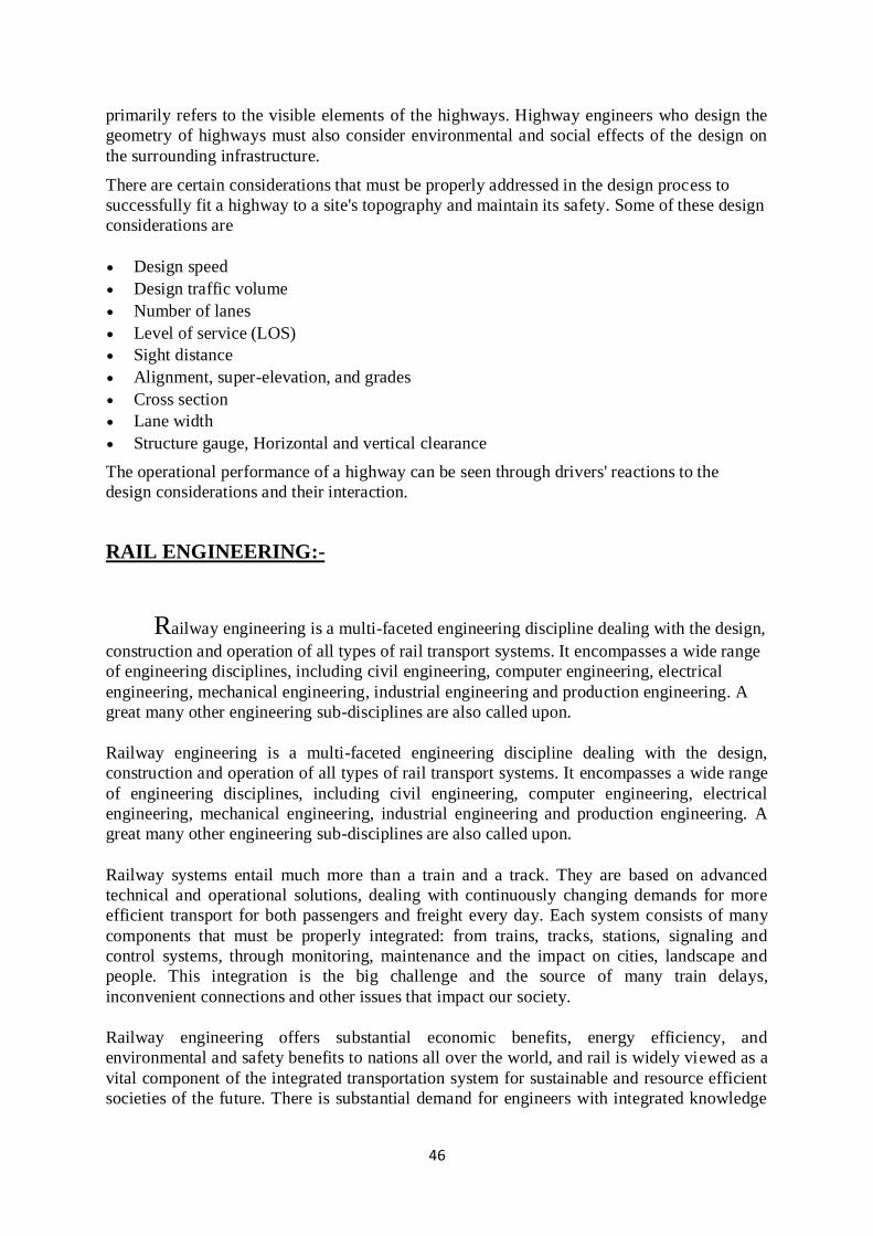
A dam is a barrier that impounds water or underground streams. Reservoirs created by dams
not only suppress floods but also provide water for activities such as irrigation, human
consumption, industrial use, aquaculture, and navigability. Hydropower is often used in
conjunction with dams to generate electricity. A dam can also be used to collect water or for
storage of water which can be evenly distributed between locations. Dams generally serve the
primary purpose of retaining water, while other structures such as floodgates or levees (also
known as dikes) are used to manage or prevent water flow into specific land regions.
fig3. Dam

44
MODULE IV
TRAFFIC AND URBAN ENGINEERING
Transportation engineering is a branch of civil engineering that is involved in the
planning, design, operation, and maintenance of safe and efficient transportation systems.
These systems include roadways, railways, waterways, and intermodal operations.
Transportation engineers are civil engineers who design highways, airports, and railway and
bus systems. They work for governmental agencies; for consulting firms that troubleshoot for
the government; and for private firms that produce materials and
equipment used in transportation.
Scope of Transportation Engineering:-
Engineers having specialised in Transportation Engineering are required by
construction companies to prepare preliminary and final plans for highways, bridges,
drainage structures, municipal utilities, roadway lighting, traffic control devices and
intelligent transportation systems.
PLANNING AND DESIGN ASPECTS OF TRNSPOTATION:-
The design aspects of transportation engineering include the sizing of transportation facilities
(how many lanes or how much capacity the facility has), determining the materials and
thickness used in pavement designing the geometry (vertical and horizontal alignment) of the
roadway (or track).
The four main stages of the transportation planning process are: (i) Transportation survey,
data collection and analysis; (ii) Use of transportation model; (iii) Future land use forecasts
and alternative policy strategies; and. (iv) Policy evaluation.
The unique purpose of transportation is to overcome space, which is shaped by a variety of
human and physical constraints such as distance, time, administrative divisions and
topography. Jointly, they confer a friction to any movement, commonly known as the friction
of distance (or friction of space).
VARIOUS MODES OF TRANSPORTATION:-
The basic modes of transportation are rail, highway, water, pipeline and air.

45
Rail. India has amongst the largest railway network in the world. ...
Road Transport. ...
Water transport. ...
Inland water transport. ...
Oceanic Transport. ...
Pipelines. ...
Air Transport.
HIGHWAY ENGINEEING:-
Highway engineering is an engineering discipline branching from civil engineering that
involves the planning, design, construction, operation, and maintenance of roads, bridges,
and tunnels to ensure safe and effective transportation of people and goods.
Standards of highway engineering are continuously being improved. Highway engineers
must take into account future traffic flows, design of highway intersections/interchanges,
geometric alignment and design, highway pavement materials and design, structural design of
pavement thickness, and pavement maintenance.
Highway planning involves the estimation of current and future traffic volumes on a road
network. The Highway planning is also a basic need for the Highway development. Highway
engineers strive to predict and analyze all possible civil impacts of highway systems. Some
considerations are the adverse effects on the environment, such as noise pollution, air
pollution, water pollution, and other ecological impacts.
Management of safety is a systematic process that strives to reduce the occurrence and
severity of traffic accidents. The man/machine interaction with road traffic systems is
unstable and poses a challenge to highway safety management. The key for increasing the
safety of highway systems is to design, build, and maintain them to be far more tolerant of
the average range of this man/machine interaction with highways. Technological
advancements in highway engineering have improved the design, construction, and
maintenance methods used over the years. These advancements have allowed for newer
highway safety innovations.
The most appropriate location, alignment, and shape of a highway are selected during the
design stage. Highway design involves the consideration of three major factors (human,
vehicular, and roadway) and how these factors interact to provide a safe highway. Human
factors include reaction time for braking and steering, visual acuity for traffic signs and
signals, and car-following behaviour. Vehicle considerations include vehicle size and
dynamics that are essential for determining lane width and maximum slopes, and for the
selection of design vehicles. Highway engineers design road geometry to ensure stability of
vehicles when negotiating curves and grades and to provide adequate sight distances for
undertaking passing manoeuvres along curves on two-lane, two-way roads.
GEOMETRIC DESIGN:-
Highway and transportation engineers must meet many safety, service, and performance
standards when designing highways for certain site topography. Highway geometric design
46
primarily refers to the visible elements of the highways. Highway engineers who design the
geometry of highways must also consider environmental and social effects of the design on
the surrounding infrastructure.
There are certain considerations that must be properly addressed in the design process to
successfully fit a highway to a site's topography and maintain its safety. Some of these design
considerations are
Design speed
Design traffic volume
Number of lanes
Level of service (LOS)
Sight distance
Alignment, super-elevation, and grades
Cross section
Lane width
Structure gauge, Horizontal and vertical clearance
The operational performance of a highway can be seen through drivers' reactions to the
design considerations and their interaction.
RAIL ENGINEERING:-
Railway engineering is a multi-faceted engineering discipline dealing with the design,
construction and operation of all types of rail transport systems. It encompasses a wide range
of engineering disciplines, including civil engineering, computer engineering, electrical
engineering, mechanical engineering, industrial engineering and production engineering. A
great many other engineering sub-disciplines are also called upon.
Railway systems entail much more than a train and a track. They are based on advanced
technical and operational solutions, dealing with continuously changing demands for more
efficient transport for both passengers and freight every day. Each system consists of many
components that must be properly integrated: from trains, tracks, stations, signaling and
control systems, through monitoring, maintenance and the impact on cities, landscape and
people. This integration is the big challenge and the source of many train delays,
inconvenient connections and other issues that impact our society.
Railway engineering offers substantial economic benefits, energy efficiency, and
environmental and safety benefits to nations all over the world, and rail is widely viewed as a
vital component of the integrated transportation system for sustainable and resource efficient
societies of the future. There is substantial demand for engineers with integrated knowledge
47
of railway subsystems (infrastructure, vehicles and traffic control) who understand how to
maximise performance of the whole system.
TRAFFIC ENGINEERING:-
Traffic engineering is a branch of civil engineering that uses engineering techniques to
achieve the safe and efficient movement of people and goods on roadways.
It focuses mainly on research and construction of the infrastructure necessary for safe and
efficient traffic flow, such as road geometry and side walks and cross walks, segregated cycle
facilities, shared lane marking, traffic signs, rod surface making and traffic lights.
URBAN ENGINEERING:-
Municipal or urban engineering applies the tools of science, art and engineering in
an urban environment.
Municipal engineering is concerned with municipal infrastructure. This involves specifying,
designing, constructing, and maintaining streets, sidewalks, water supply
networks, sewers, street lighting, municipal solid waste management and disposal, storage
depots for various bulk materials used for maintenance and public works (salt, sand,
etc.), public parks and cycling infrastructure.
In the case of underground utility networks, it may also include the civil portion (conduits
and access chambers) of the local distribution networks of electrical and telecommunications
services. It can also include the optimizing of garbage collection and bus service networks.
Some of these disciplines overlap with other civil engineering specialties, however municipal
engineering focuses on the coordination of these infrastructure networks and services, as they
are often built simultaneously (for a given street or development project), and managed by
the same municipal authority.
The development of different strands of knowledge necessary for the management of
municipal infrastructure led to the emergence of separate specialised institutions, including:
For drainage: Chartered Institution of Water and Environmental Management, 1895
For town planning: Town Planning Institute 1914 ... subsequently becoming the Royal
Town Planning Institute
For street lighting: Association of Public Lighting Engineers, 1934...subsequently
becoming the Institution of Lighting Engineers
For highway engineering: Institution of Highways and Transportation, 1930
For public housing: Institute of Housing, 1931
In 1984 the Institution of Municipal Engineers merged with the Institution of Civil Engineers.