Embed Size (px)
Citation preview
KIT# 4408-111/4/13
KSR
O
A
D
M
A
S
T
E
R,
I
N
C.
ROADMASTER, Inc. 6110 NE 127th Ave. Vancouver, WA 98682 360-896-0407 fax 360-735-9300 www.roadmasterinc.com
BASEPLATE KIT INSTALLATION INSTRUCTIONS
1
2
6
7
8
9
11
14
12
13
IF REQUIRED
3
4
5
10
15 16
17
IF REQUIRED
ITEM QTY NAME MATERIAL1...........4...........1/2” x 2 1/2” BOLT ..................................................................................... 350099-002...........4...........1/2” LOCK WASHER ................................................................................. 350309-003...........2...........10mm x 1.5 x 40mm BOLT ........................................................................ 356103-004...........2...........10mm LOCK WASHER ............................................................................. 355715-005...........2...........3/8” FLAT WASHER .................................................................................. 350304-006...........2...........5/8” DRAW PIN W/ CLIP ........................................................................... 357035-007...........2...........QUICK LINK .............................................................................................. 200008-008...........2...........SAFETY CABLE ........................................................................................ 650646-089...........4...........1” O.D. x 0.188 WALL x 1” ROUND TUBE ................................................A-00002810.........4...........1” O.D. x 0.188 WALL TUBE x 3/4” ...........................................................A-00011211 .........4...........3/16” PLATE x 1 1/4” x 1 1/2” ....................................................................A-00307512.........1...........DRIVER SIDE ARM ..................................................................................C-00150813.........1...........PASSENGER SIDE ARM ..........................................................................C-00150914.........1...........MAIN RECEIVER ......................................................................................C-00151015.........2...........6mm x 1.0 x 35mm BOLT .......................................................................... 355896-0016.........2...........1/4” LOCK WASHER ................................................................................. 350301-0017.........2...........1/4” FLAT WASHER .................................................................................. 350300-00
KIT# 4408-111/4/13
KS
IMPORTANT: All brackets must be assembled with all the bolts left loose for final adjustment and positioning (before tightening) unless otherwise instructed. All bolts must be torqued for proper strength. If more than one bolt is used per fastening point, the diagram may only show one.
• Use flat washers over all slotted holes • Use lock washers on all fasteners
• Installation of most mounting brackets requires moderate mechani-cal aptitude and skills. We strongly recommend professional installa-tion by an experienced installer.
• The installer must read the instructions and use all bolts and partssupplied. Failure to do so could result in loss of the towed vehicle.
• Use Loctite® Red on all bolts used for mounting this bracket.
• Every 3,000 miles, the owner must inspect the fasteners for propertorque, according to the bolt torque requirements chart on the last pageof these instructions. The owner must also inspect all mounts andbrackets for cracks or other signs of fatigue every 3,000 miles.Failure to do so could result in loss of the towed vehicle.
• The owner must check the vehicle manufacturer's instructions forthe proper procedure(s) to prepare the vehicle for towing. Somevehicles must be equipped with a transmission lube pump, an axle dis-connect, driveline disconnect or free-wheeling hubs before they can betowed. Failure to properly equip the vehicle will cause severe damageto the transmission.
• If running changes were made by the vehicle manufacturer after thisbracket was designed, some bolts or other fasteners in the hardwarepack may no longer be the correct size. It is the installer’s responsi-bility to verify that the bracket is securely fastened to the vehicle andfitted with the correct hardware to account for these changes. Failure tosecurely fasten the bracket could result in loss of the towed vehicle.
• If the towed vehicle has been in an accident, it must be properly re-paired before attaching the bracket. Do not install the bracket if anystructural frame damage is found. Failure to repair the damage couldresult in the loss of the towed vehicle.
ROADMASTER Limited Warranty, including One-Year Conditional Warranty Text and Product Registration Card, in Carton.
• Roadmaster manufactures many styles of brackets. If your brackethas removable arms, they must be removed before driving thevehicle, unless the arms can be pinned or padlocked in place.If not secured, the arms could vibrate out, resulting in non-warrantydamage or personal injury.
• Some motorhome chassis have such a tight turning radius that you candamage your motorhome, towed vehicle, tow bar or bracket while turningsharply. Before getting on the road, test your turning radius in anempty parking lot. Turning too sharply could result in non-warrantydamage to towing system, motorhome and/or towed vehicle.
• Do not back up with the towed vehicle attached or non-warrantydamage will occur to your towing system, motorhome and/or towedvehicle.
• The safety cables must connect the towing vehicle to the towedvehicle frame to frame, with the cables crossed, with enough slackfor sharp turns. Refer to the cable instructions for proper routing.Failure to leave enough slack in the safety cables, or failure to connectthe safety cables frame to frame, will result in the loss of the towedvehicle.
• This bracket is designed for use with ROADMASTER tow bars andROADMASTER adaptors only. Using this bracket with other brands,without an approved ROADMASTER adaptor, may result in non-warranty damage or injury.
• Do not use this document for custom fabrication, as it may not showall parts or structural components. Custom fabrication or an attempt tocopy this bracket design could result in loss of the towed vehicle.
• Upon final installation, the installer must inspect the bracket to en-sure adequate clearance, particularly around hoses, air conditionerlines, radiators, etc., or non-warranty damage to the towed vehiclewill result.
• This bracket is only warranteed for the original installation. Installinga used bracket on another vehicle is not recommended and will voidthe warranty.
Failure to follow these instructions can result in property damage, personal injury or even death.WARNINGWARNING
Fig.A
Fig.B
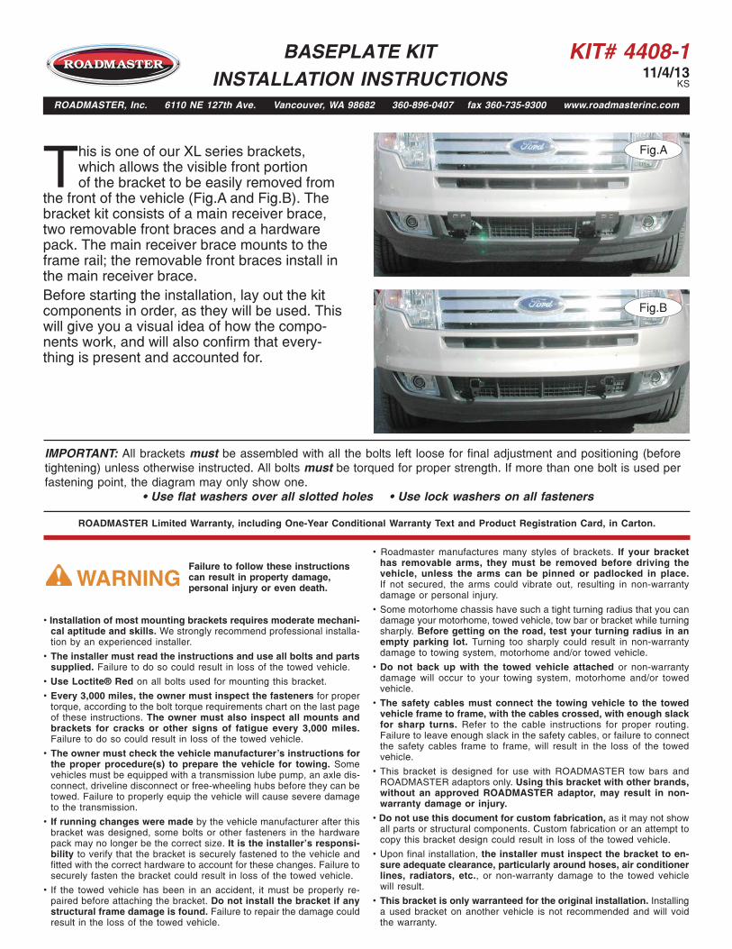
This is one of our XL series brackets, which allows the visible front portion of the bracket to be easily removed from
the front of the vehicle (Fig.A and Fig.B). The bracket kit consists of a main receiver brace, two removable front braces and a hardware pack. The main receiver brace mounts to the frame rail; the removable front braces install in the main receiver brace. Before starting the installation, lay out the kit components in order, as they will be used. This will give you a visual idea of how the compo-nents work, and will also confirm that every-thing is present and accounted for.
BASEPLATE KIT INSTALLATION INSTRUCTIONS
ROADMASTER, Inc. 6110 NE 127th Ave. Vancouver, WA 98682 360-896-0407 fax 360-735-9300 www.roadmasterinc.com
KIT# 4408-111/4/13
KS
All illustrations and specifications contained herein are based on the latest information available at the time of publication approval. ROADMASTER, INC. reserves the right to make changes at any time without notice in material, specification and models or to discontinue models.
Fig.C Fig.D Fig.E
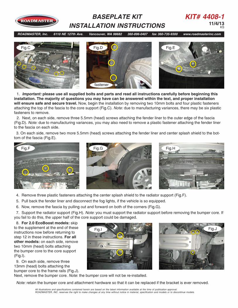
1. Important: please use all supplied bolts and parts and read all instructions carefully before beginning thisinstallation. The majority of questions you may have can be answered within the text, and proper installation will ensure safe and secure travel. Now, begin the installation by removing two 10mm bolts and four plastic fasteners attaching the top of the fascia to the core support (Fig.C). Note: due to manufacturing variances, there may be six plastic fasteners to remove.
Fig.G Fig.HFig.F
4. Remove three plastic fasteners attaching the center splash shield to the radiator support (Fig.F).
5. Pull back the fender liner and disconnect the fog lights, if the vehicle is so equipped.
6. Now, remove the fascia by pulling out and forward on both of the corners (Fig.G).
7. Support the radiator support (Fig.H). Note: you must support the radiator support before removing the bumper core. Ifyou fail to do this, the upper half of the core support could be damaged.
Fig.I Fig.J
2. Next, on each side, remove three 5.5mm (head) screws attaching the fender liner to the outer edge of the fascia(Fig.D). Note: due to manufacturing variances, you may also need to remove a plastic fastener attaching the fender liner to the fascia on each side.
3. On each side, remove two more 5.5mm (head) screws attaching the fender liner and center splash shield to the bot-tom of the fascia (Fig.E).
8. For 2.0 EcoBoost models: skipto the supplement at the end of these instructions now before returning to step 12 in these instructions. For all other models: on each side, remove two 10mm (head) bolts attaching the bumper core to the core support (Fig.I).
9. On each side, remove three13mm (head) bolts attaching the bumper core to the frame rails (Fig.J). Next, remove the bumper core. Note: the bumper core will not be re-installed.
Note: retain the bumper core and attachment hardware so that it can be replaced if the bracket is ever removed.
BASEPLATE KIT INSTALLATION INSTRUCTIONS
ROADMASTER, Inc. 6110 NE 127th Ave. Vancouver, WA 98682 360-896-0407 fax 360-735-9300 www.roadmasterinc.com
fastener
KIT# 4408-111/4/13
KS
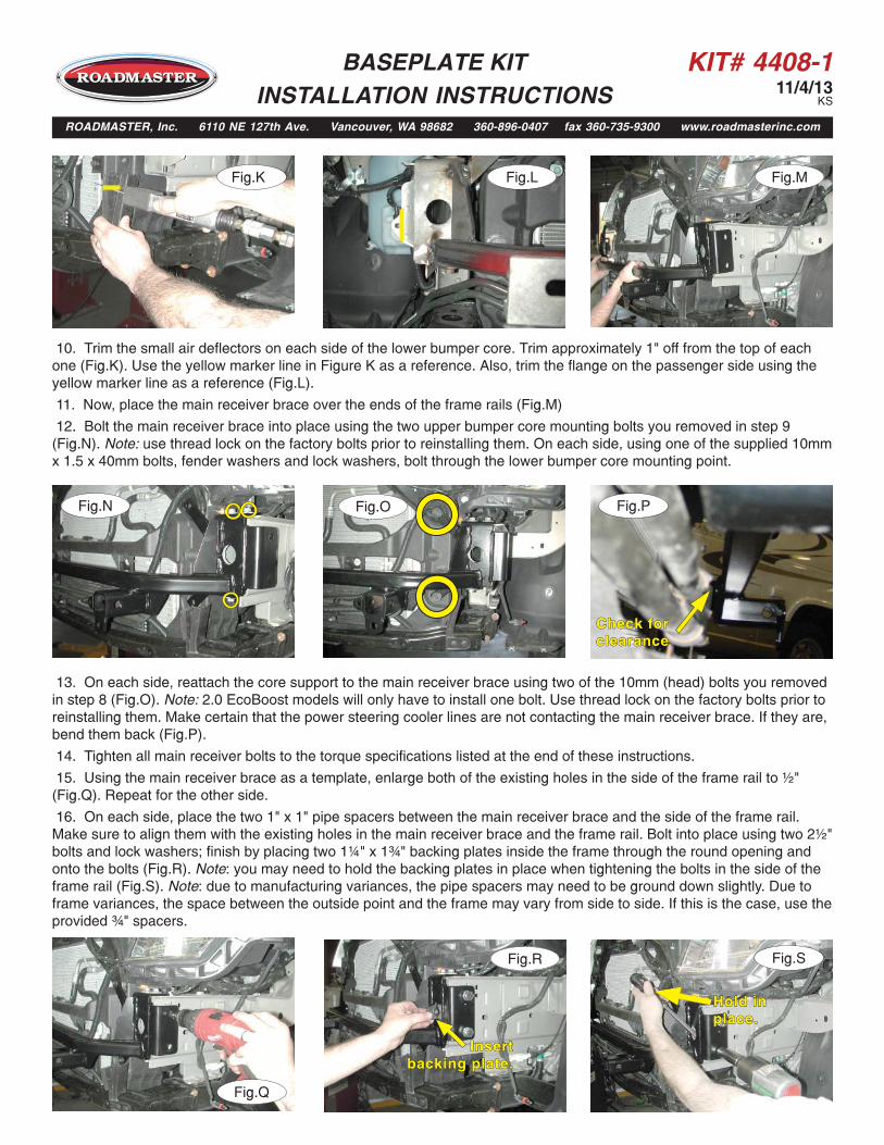
10. Trim the small air deflectors on each side of the lower bumper core. Trim approximately 1" off from the top of eachone (Fig.K). Use the yellow marker line in Figure K as a reference. Also, trim the flange on the passenger side using theyellow marker line as a reference (Fig.L).
11. Now, place the main receiver brace over the ends of the frame rails (Fig.M)
12. Bolt the main receiver brace into place using the two upper bumper core mounting bolts you removed in step 9(Fig.N). Note: use thread lock on the factory bolts prior to reinstalling them. On each side, using one of the supplied 10mmx 1.5 x 40mm bolts, fender washers and lock washers, bolt through the lower bumper core mounting point.
Fig.M
Fig.N Fig.P
Fig.Q
13. On each side, reattach the core support to the main receiver brace using two of the 10mm (head) bolts you removedin step 8 (Fig.O). Note: 2.0 EcoBoost models will only have to install one bolt. Use thread lock on the factory bolts prior toreinstalling them. Make certain that the power steering cooler lines are not contacting the main receiver brace. If they are,bend them back (Fig.P).
14. Tighten all main receiver bolts to the torque specifications listed at the end of these instructions.
15. Using the main receiver brace as a template, enlarge both of the existing holes in the side of the frame rail to ½"(Fig.Q). Repeat for the other side.
16. On each side, place the two 1" x 1" pipe spacers between the main receiver brace and the side of the frame rail.Make sure to align them with the existing holes in the main receiver brace and the frame rail. Bolt into place using two 2½"bolts and lock washers; finish by placing two 1¼" x 1¾" backing plates inside the frame through the round opening andonto the bolts (Fig.R). Note: you may need to hold the backing plates in place when tightening the bolts in the side of theframe rail (Fig.S). Note: due to manufacturing variances, the pipe spacers may need to be ground down slightly. Due toframe variances, the space between the outside point and the frame may vary from side to side. If this is the case, use theprovided ¾" spacers.
Fig.O
Fig.K
Fig.SFig.R
InsertInsertbacking plate.backing plate.
Hold in Hold in place.place.
Fig.L
Check for Check for clearanceclearance
BASEPLATE KIT INSTALLATION INSTRUCTIONS
ROADMASTER, Inc. 6110 NE 127th Ave. Vancouver, WA 98682 360-896-0407 fax 360-735-9300 www.roadmasterinc.com

KIT# 4408-111/4/13
KS
17. Tighten all bolts to the torque specifications listed at the end of these instructions.
18. To allow clearance for the radius of the cross bar and the main receiver brace, the fascia will need to be trimmed. For'07 to '10 Ford Edge models, refer to Figures T and U; for '11 to '13 Ford Edge models, refer to the supplemental trim-ming instructions found at the end of these instructions. For '07 to '10 Lincoln MKX models, refer to Figures V and W forcorrect trimming of the fascia and Figure X as a reference for trimming the center portion flush with the grille insert. For'11 to '13 Lincoln MKX models, refer to Figures Y and Z for trimming. For all models, complete trimming on both sidesof the fascia.
Fig.T Fig.U
Lincoln MKX driver side
Fig.V
Fig.XFig.W
Passenger side
19. Now, reinstall the fascia revers-ing steps 1 through 6.
20. Fit the removable front bracesinto the front receiver brace, and se-cure them in place with the supplied5/8" draw pins and spring pins.
21. Attach the 8" safety cables withthe cable connectors (Q-Links) to thereceiver braces (Fig.AA) and attachthe ends of the safety cables to the
BOLT TORQUE REQUIREMENTS
METRIC BOLTSThread Size Grade Plated / Unplated12mm-1.25 ........8.8 ............70 ft./lb. 65 ft./lb. 12mm-1.5 ..........8.8 ............66 ft./lb. 61 ft./lb.12mm-1.75 ........8.8 ...........65 ft./lb. 60 ft./lb.14mm-2.0 ..........8.8 .........104 ft./lb. 97 ft./lb.
METRIC BOLTSThread Size Grade Plated / Unplated 8mm-1.0 ............8.8 ............20 ft./lb. 18 ft./lb. 8mm-1.25 .........8.8 ............19 ft./lb. 18 ft./lb.10mm-1.25 ........8.8 ...........38 ft./lb. 36 ft./lb.10mm-1.5 ..........8.8 ...........37 ft./lb. 35 ft./lb.
STANDARD BOLTSThread Size Grade Torque5/16..................... 5 ........................... 13 ft./lb. 3/8....................... 5 ........................... 23 ft./lb.7/16..................... 5 ........................... 37 ft./lb.1/2....................... 5 ........................... 56 ft./lb.5/8....................... 5 ......................... 150 ft./lb.
Note: The torque values represented below are intended as general guidelines. Torque requirements for specific applications may vary. Roadmaster does not warrant this information to be accurate for all applications and disclaims all liability for any claims or damages which may result from its use.
Fig.Y
Fig.Z
tow vehicle's safety cables and tow bar.
22. Install the tow bar to the mounting bracket according to the manufacturer's instructions.
Note: if the bracket is so equipped, the holes in the alignment tabs which are welded to the arms and main receiverbraces are for padlocks only. Under no circumstances should you bolt the alignment tabs together. Bolting the alignment tabs together may result in non-warranty damage to the bracket.
Fig.AA
BASEPLATE KIT INSTALLATION INSTRUCTIONS
ROADMASTER, Inc. 6110 NE 127th Ave. Vancouver, WA 98682 360-896-0407 fax 360-735-9300 www.roadmasterinc.com

KIT# 4408-111/4/13
KS
All illustrations and specifications contained herein are based on the latest information available at the time of publication approval. ROADMASTER, INC. reserves the right to make changes at any time without notice in material, specification and models or to discontinue models.
Supplemental trimming instructions for '11 to '13 Ford Edge models
1. On each side, remove the outside bumper insert by releasing three plastic clips, if the vehicle is so equipped (Fig.A).Note: the bumper inserts will not be replaced. Retain the bumper inserts for replacement in case the bracket is ever re-moved.
Fig.A
2. Mark the fascia for trimming to allow clearance for themain receiver brace. Use the yellow lines in Figure B as a guide for trimming. Note: due to manufacturing variances, if your fascia is a solid pattern like the one shown in Figure C, use the yellow lines in Figure C as a reference for trim-ming the front of the fascia. Then, use the yellow lines in Figure B as a reference for trimming the back upper lip of the fascia.
Now, proceed to step 19 in the main instructions to fin-ish this installation.
Fig.B
BASEPLATE KIT INSTALLATION INSTRUCTIONS
ROADMASTER, Inc. 6110 NE 127th Ave. Vancouver, WA 98682 360-896-0407 fax 360-735-9300 www.roadmasterinc.com
Fig.C
KIT# 4408-111/4/13
KS
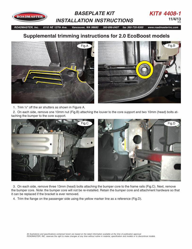
Supplemental trimming instructions for 2.0 EcoBoost models
1. Trim ½" off the air shutters as shown in Figure A.
2. On each side, remove one 10mm nut (Fig.B) attaching the louver to the core support and two 10mm (head) bolts at-taching the bumper to the core support.
Fig.A Fig.B
BASEPLATE KIT INSTALLATION INSTRUCTIONS
ROADMASTER, Inc. 6110 NE 127th Ave. Vancouver, WA 98682 360-896-0407 fax 360-735-9300 www.roadmasterinc.com
Fig.C Fig.D
3. On each side, remove three 13mm (head) bolts attaching the bumper core to the frame rails (Fig.C). Next, removethe bumper core. Note: the bumper core will not be re-installed. Retain the bumper core and attachment hardware so that it can be replaced if the bracket is ever removed.
4. Trim the flange on the passenger side using the yellow marker line as a reference (Fig.D).
All illustrations and specifications contained herein are based on the latest information available at the time of publication approval. ROADMASTER, INC. reserves the right to make changes at any time without notice in material, specification and models or to discontinue models.
KIT# 4408-111/4/13
KS
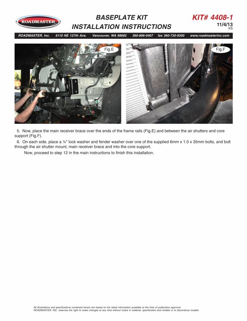
5. Now, place the main receiver brace over the ends of the frame rails (Fig.E) and between the air shutters and coresupport (Fig.F).
6. On each side, place a ¼" lock washer and fender washer over one of the supplied 6mm x 1.0 x 35mm bolts, and boltthrough the air shutter mount, main receiver brace and into the core support.
Now, proceed to step 12 in the main instructions to finish this installation.
BASEPLATE KIT INSTALLATION INSTRUCTIONS
ROADMASTER, Inc. 6110 NE 127th Ave. Vancouver, WA 98682 360-896-0407 fax 360-735-9300 www.roadmasterinc.com
Fig.E Fig.F
All illustrations and specifications contained herein are based on the latest information available at the time of publication approval. ROADMASTER, INC. reserves the right to make changes at any time without notice in material, specification and models or to discontinue models.