Embed Size (px)
Citation preview

Journal of Computers Vol. 28, No. 3, 2017, pp. 205-214
doi:10.3966/199115592017062803017
205
Based on FPGA Method to Design and Implement for
Induction Motors Drive System
Shyh-Shing Perng1, Ter-Feng Wu1, Maoh-Chin Jiang1, Chih-Wen Li1, and Yi-Ru Jiang2
1 Department of Electrical Engineering, National Ilan University
Yilan 260, Taiwan, ROC
{ssperng, tfwu, mcjiang, cwli}@niu.edu.tw
2 Taipei Municipal Muzha Vocational High School
Taipei 116, Taiwan, ROC
Received 18 June 2015; Revised 19 February 2016; Accepted 27 December 2016
Abstract. Induction motor is currently the mainstream in industrial motion control and is
frequently used in industrial mechanics, precision automation, electric vehicles, etc. The global
market scale of induction motor drive industry has reached billions of dollars and is increasing
with an annual growth rate of 15%. In response to industrial needs, it is a trend for universities
to establish theoretical and experimental lectures of motor drive control, in order to nurture
domestic talents. “Control of Electrical Drives” is a subject that combines Electrical Machinery,
Power Electronics, Control Systems, Sensor Technology, Applications of Microprocessor and
System-on-chip. Since it contains so many different disciplines, it is difficult for students to
absorb. One crucial factor that determines the learning result is the construction of suitable
teaching materials and experiment devices. The experimental platform constructed in this article
is a digital motor drive system based on FPGA (Field Programmable Gate Array). All the
experiments of electrical drives are proceeding in the environment of SIMULINK. The results
can be directly copied and used by various control icons of different functions, making it easy to
test and verify the theories and experiments of motor controls. Thus, the barriers to learning can
be reduced and the time for students to debug can decline.
Keywords: FPGA, induction motors, SIMULINK
1 Introduction
Control of Electrical Drives is the mainstream of the current industrial motion control. It can be seen in
general industrial machinery, precision automation machinery, electric cars, railway, etc. So far, the
business opportunity of global motor drive industry has reached billions of U.S. dollars, with an annual
growth rate of 15%. In response to the industrial demands, it is the trend to set up the control of electrical
drives theory and experiment courses in colleges and departments of electrical engineering [1]. If the
undergraduates of department of electrical engineering could receive related implement training at school,
it would significantly reduce the costs of R & D and personnel training for companies.
For students of electrical engineering, who have had the basic knowledge of control of electrical drives,
the greatest difficulty lies in the realization that meets the industrial demand. In some circumstances, with
a chosen DSP chip and completed hardware, students still don’t know how to implement. In order to do
so, students need to understand and apply central processing unit, memory allocation, peripheral
components, interrupt mechanism, time series planning, assembly language, development environment,
linking, etc. However, students can only access to information like the English website of the chip
manufacturers, manuals, and the project-based textbooks published by the domestic publishers. These
resources are all difficult to absorb, which leads to the result of ineffective learning. The graduate
students can do the time-consuming exploration on their own, but this method is rather impossible for the
Based on FPGA Method to Design and Implement for Induction Motors Drive System
206
undergraduates. Consequently, “Control of Electric Drives” became a daunting discipline for students.
“Control of Electrical Drives” is a subject that integrates electrical machinery, power electronics,
control systems, sensors and transducers, application of microprocessor and single chip. Since it covers
multiple disciplines, the teaching materials should be carefully selected and integrated. The experiment
equipment should also be properly developed. The commonly seen laboratories in Departments of
Electrical Engineering are electrical machinery lab, power electronics lab, microprocessors lab and
system-on-chip lab. However, for these laboratories, it is difficult to construct a motor drive control
experiment system with control software. This is the main obstacle that universities are facing when
setting up the “Control of Electrical Drives " course.
In order to solve this difficulty, multiple literatures are contributed to the improvement of equipment
for the lessons and curriculum planning. For example, Mok showed how to construct a DC motor drive
system by utilizing 3D simulation software to provide a more accurate and interesting learning
environment [2]. Ayasun used the MATLAB / SIMULINK software to simulate the three-phase
induction motor in a no-loaded and blocked experiment, in order to obtain the parameters of single-phase
equivalent circuit model [3]. Blanque established an experimental platform of the reluctance motor drive
system, together with the theoretical and experimental curriculum planning [4]. Montesinos came up with
the experimental platform of a DSP-based, brushless DC motor drive system, and the related curriculum
planning [5]. Rodriguez-Resendiz has implemented a servo system laboratory course in a LabVIEW
environment [6]. Anand. has developed a “Power Electronics and Drives Experimental Bench” (PEDEB).
By using the PEDEB, we can observe and learn an induction motor drive [7].
In the last decade, with the progress and development of ultra large scale integrated circuits (ULSI),
the synthesized analog circuit has gradually been replaced by the more flexible microprocessor (µP) and
digital signal processing (DSP). Sometimes, it is even replaced by the Embedded Development Kit (EDK)
based on FPGA chips [8], to implement the high-performance motor drive system control. This provides
the programmable hardware and software which have better flexibility. Students, who study the DSP and
FPGA chip of motor drive control system, would need to verify the feasibility and system performance.
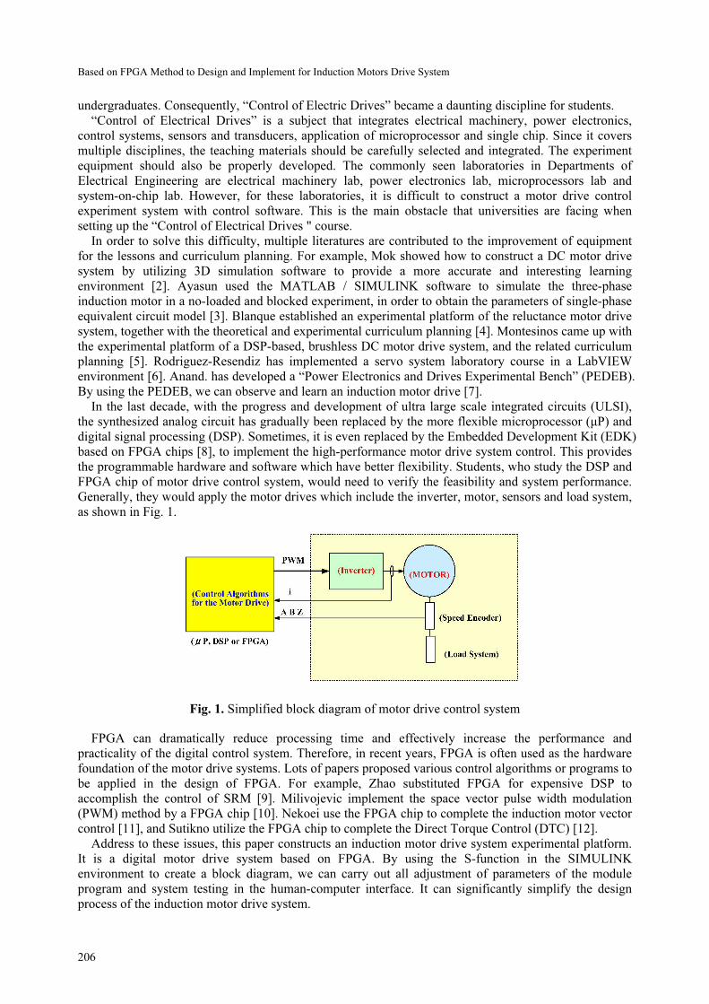
Generally, they would apply the motor drives which include the inverter, motor, sensors and load system,
as shown in Fig. 1.
Fig. 1. Simplified block diagram of motor drive control system
FPGA can dramatically reduce processing time and effectively increase the performance and
practicality of the digital control system. Therefore, in recent years, FPGA is often used as the hardware
foundation of the motor drive systems. Lots of papers proposed various control algorithms or programs to
be applied in the design of FPGA. For example, Zhao substituted FPGA for expensive DSP to
accomplish the control of SRM [9]. Milivojevic implement the space vector pulse width modulation
(PWM) method by a FPGA chip [10]. Nekoei use the FPGA chip to complete the induction motor vector
control [11], and Sutikno utilize the FPGA chip to complete the Direct Torque Control (DTC) [12].
Address to these issues, this paper constructs an induction motor drive system experimental platform.
It is a digital motor drive system based on FPGA. By using the S-function in the SIMULINK
environment to create a block diagram, we can carry out all adjustment of parameters of the module
program and system testing in the human-computer interface. It can significantly simplify the design
process of the induction motor drive system.

Journal of Computers Vol. 28, No. 3, 2017
207
2 The Experimental Platform of Induction Motor
The control of electrical drives experimental platform, constructed in this paper, uses the FPGA chip as
the control center. We created a complete digitized induction motor drive system. It can be divided into
four main parts as shown in Fig. 2. Fig. 3 shows the appearance of the experimental platform for the
motor drive system.
Fig. 2. Induction motor drive system experimental platform block diagram
Fig. 3. Photo of the induction motor drive system experimental platform appearance
2.1 System Monitoring Module
It includes 586CPU, 64MB of memory RAM and an 8MB disk-on-chip (DOC). Thus, the platform can
be connected with PC through the Internet to execute programs, monitoring and managing.
2.2 The FPGA Module
The FPGA module is the control center of the motor drive system experimental platform. It consists of a
large-scale programmable logic gate FPGA # 1 which uses the Xilinx product XC2V250 of Virtex-II
series. Any application, written in VHDL language on a PC, can be downloaded into the FPGA for

Based on FPGA Method to Design and Implement for Induction Motors Drive System
208
implementation testing and verification. This experimental platform has implanted a 16-bit DSP core in
the FPGA, responsible for real-time control. This DSP core, constructed by software, is designed for
controlling. Thus, the assembly language concisely plans 29 instructions according to different
controlling conditions. By using these 29 instructions in programming, we can eliminate the traditional
DSP chips in applications. The DSP core and the 586CPU are directly connected by dual-port memory,
with the sampling frequency up to 32 KHz. All data and programs within DSP can be read, wrote, setup
and managed by 586CPU.
2.3 I / O Interface Module
The I / O interface module contains eight channels of 12-bit ADC, four channels of 12-bit DAC and a
smaller FPGA # 2, which satisfies the requirement of analog output in the interface design for the system.
Induction motor experiment module can only be connected with the FPGA # 2. Thus control of I/O
interface of FPGA # 1 must be done through FPGA # 2.
2.4 Motor Drive Module
The motor drive modules include servo interface, power driver, and motor, as shown in Fig. 2. The servo
interface can generate six sets of PWM control signals, in order to control six power switches in the
driver. It includes the switch protection and startup protection in order to control the motors. The current
sampling signals of A / D and angle feedback signal both maintain 12-bit resolution.
3 Data Structural of Induction Motors Drive System
Generally, the motor drive system design can be divided into two categories, the software method or the
hardware method, according to the implementation of digital control programming. For the software
method, we first design the DSP core in FPGA [13]. Then, we design the motor driver control software
for the DSP core. The controlled method is implemented by software execution. Another method is the
direct implementation of hardware circuit. We directly design logic circuits in FPGA to implement the
motor drive. In comparison, the software method has more flexibility since the control structure and
internal parameters are easier to be modified. The hardware method is relatively more rigid, due to the
restriction that any control framework changes must also include the modification of the hardware circuit.
Thus, in a control structure that is not yet confirmed, it is difficult to design a hardware circuit. Our
experiments will base on software design. We will use S FUNTION in the SIMULINK environment to
generate block diagrams, so that all adjustments of parameters in the module program and system testing
can be carried out in the man-machine interface provided by SIMULINK. This would greatly simplify
the motor control experiment design process, as shown in Fig. 4. All data in DSP core is saved in the
memory. Via reading, writing, operating and managing the memory, we can control the entire operation
of the DSP core. Through the connection interface between the FPGA # 2 and servo interface, we can
input signals of the servo interface feedback current, motor speed, etc. into a specific memory. Once the
system program is compiled, we can download the circuit file into the FPGA # 1 and FPGA # 2. We also
download the machine code and microcode file into the DSP core of the FPGA # 1. Then, we can start
testing and monitoring the system. In addition, through the ISA-bus, 586CPU can both read and write all
data in the DSP core, I/O interface area, data area, program area, micro-code and stack information in
FPGA # 1, for testing and monitoring the digital data of the experiment system. Also, we implanted
oscilloscope and logic analyzer functions in the LCD monitor module, which can monitor real-time
waveform of the experiment system action.
4 Building the Motor Drive Control Box Module
SIMULINK is a simulation tool established under the MATLAB environment, which provides multi-
graphic function blocks. Users can conveniently link to or establish a control system block diagram, for
the simulation or experiment. This can significantly simplify the design process, and reduce designers’
burden. The most important feature is that, we can establish a user-defined function block with a strong
scalability by using the S-FUNCTION. At the same time, we could be able to communicate with

Journal of Computers Vol. 28, No. 3, 2017
209
applications of file type *.dll, to achieve integration and application. In this paper, we use the S-
FUNCTION to establish the corresponding block, so that the links of the system programs, the
adjustment of parameters of the module program and system testing and monitoring can all be completed
in the man-machine interface provided by SIMULINK.
Fig. 4. Data structural of the induction motors drive system
4.1 The Module Program for Constructing Control box
The module program of each control block is written in assembly language. The data structure of the
modular program is shown in Fig. 5, which each program is a subroutine structure and end with the RET
instruction. When the system executes real-time control program after links to multiple modules, it will
automatically calls the relative procedures by turns. After all modules have been executed, the system
would then return control power to other programs. Fig. 6 shows a flow chart of the module program for
the system to perform real-time control.
Fig. 5. Simplified block diagram of motor drive control system

Based on FPGA Method to Design and Implement for Induction Motors Drive System
210
Fig. 6. Flow chart of the real-time control of module program
4.2 Create a Module Program Corresponding to the SIMULINK Control Block Diagram
Programs completed according to the data structure of the modular design mentioned above, uses S-
FUNCTION to create corresponding graphical box. Fig. 7 shows an example of graphical block module
program. Fig. 7 (a) is the corresponding control block diagram of S-FUNCTION. Fig. 7 (c) is the
window for the parameter adjustment and Fig. 7 (c) shows the original assembly language of module
program. This module function is for the calculation of the motor rotation angle, where the input signal is
the motor angular velocity and the input signal is the motor rotation angle. We use an integer from 0 to
255 to represent the motor rotation angle from 0 to 360 degrees. Transforming the formula above to a
discrete relationship can be expressed as, in which is the discrete sampling time.
The motor control block diagrams, of various functions constructed under the SIMULINK
environment, can be shown in Fig. 8. In the SIMULINK environment, we can select the desired control
block diagram, complete the input and output connection of the system and control parameter settings.
After that, we can conduct the system testing, making the motor-driven experiments as easy and
convenient as circuit simulation.
5 Implementation of FPGA-Based Induction Motors Drive System
Generally, current high-performance induction motor drive system uses the vector control technology
[14]. Fig. 9 is a block diagram of the AC induction motor vector control. The basic concept of the AC
induction motor vector control technology is to transform the current signal of the motor to a coordinate
system of the synchronous speed by using coordinate transformation. Then, through the decoupling
control, it can divide into two equivalent and mutually perpendicular current component. One is
equivalent to the field current, and the other is equivalent to the torque current. We can control the
magnitude of the magnetic field current component and torque current component by adjusting the
magnitude, phase and frequency of the induction motor three-phase stator current. Moreover, we can
control the rotation speed and output torque of the AC induction motor to achieve high performance
similar to the control of DC separately excited motor.

Journal of Computers Vol. 28, No. 3, 2017
211
Fig. 7. Under the SIMULINK environment, (a) establish the control block diagram corresponding to S-
function, (b) parameter adjustment window, (c) the source assembly language of module program
Fig. 8. The motor control block diagrams constructed under the SIMULINK environment

Based on FPGA Method to Design and Implement for Induction Motors Drive System
212
*
eT
1/s
*
rω
rω
slω
r
rλ
32→
23→
eω
Speed
controller
Flux
controller
Current
controller
Current
controller
Decoupling
circuit
AC
motor
Interface
Board Driver
Rotor flux
model
Field
weakening
Coordin.
Transt.
Coordin.
Transt.
Fig. 9. Block diagram of the AC induction motor vector control
Fig. 10 is the system block diagram of induction motor vector control experiment, designed and
accomplished under the SIMULINK environment. The system uses the 16-bit integer arithmetic and
powers of two scaling, also known as radix point-only scaling [15]. The voltage signals use the Q4 mode,
the flux and current signals use the Q10 mode, and the speed signals use the Q6 mode.
Q10
Q10
wr_m(Q0)
(rpm)Q6
0~255
wr_ele(Q6)
(rad/sec)Q10
Q10
Q6
Q4 Q4
Q4
Q10Q10
Wsl
iqr
1/lamdar
wsl
wsl
wedeg
we2deg
Vol_dec
vdr
vqr
we
lamdar
idr
iqr
vdr*
vqr*
vol_dec
Switch_IC
switch1
In1 Out1
speed controller
K O
lamdar=0.69
K_8
k=3432
In1 Out1
flux controller
Flux idrlamdar
flux
In1 Out1
current controller
In1 Out1
current controller
TRG
TRG
+
+
SUM
+
-
SUB3
+
-
SUB2
+
-
SUB1
+
-
SUB
O
RAMP1 wave1
LPF_1D
LPF_1D
ucmd (0.1 V)
vcmd ( 0.1 V)
wcmd (0.1 V)
iu (Q10 A)
iv (Q10 A)
iw (Q10 A)
wrm (rpm)
Induction motor1
KO
Constant
CH4
CH4
CH3
CH3
CH2
CH2
CH1
CH1
3s -> 2s
3s_2s
2w --> 2s
in_d
in_q
ang
out_d
out_q
2w ---> 2s1
2s -> 3s
2s_3s
2s --> 2w
in_d
in_q
ang
out_d
out_q
2s ----> 2w1
Fig. 10. The induction motor vector control experiment system designed and accomplished under the
SIMULINK environment
The controlled motor used in the experiment is the TECO 220V, 1Hp, three phase AC induction motor,
system power-level DC Bus voltage is 280V, and the work sampling frequency is 8KHz. After started,
the system first establishes magnetic flux of the d-axis, and adds the 500RPM the speed command at the
0.5 seconds. Fig. 11 shows the experiment result waveform of induction motor vector control. Fig. 12
shows the response waveform of simulation results. According to the simulation and experimental results,
we found that the measured current and speed waveforms were almost identical to the simulation results.
We can conclude that the theoretical and experimental results perform mutual authentication.

Journal of Computers Vol. 28, No. 3, 2017
213
0 0.5 1 1.5-100
0
100
v bs
(V
)
0 0.5 1 1.5-2
0
2
i bs
(A)
0 0.5 1 1.5
0
200
400
600
wr ,
wr*
(rp
m)
time(s)
0 0.5 1 1.5
0
100
200
vdr ,
vqr
(V
)
0 0.5 1 1.5
-2
0
2
4
i dr ,
iqr
(A
)
0 0.5 1 1.50
0.5
1
λr
time(s)
Vqr
Vdr
iqr
iqr
Fig. 11. The experiment result of induction motor vector control
0 0.5 1 1.5-100
0
100
v bs (V
)
0 0.5 1 1.5-2
0
2
i bs (A
)
0 0.5 1 1.5
0
200
400
600
wr , w
r* (
rpm
)
time(s)
0 0.5 1 1.5
0
100
200
vdr ,
vqr
(V
)
0 0.5 1 1.5
-2
0
2
4
i dr ,
i q
r (A
)
0 0.5 1 1.50
0.5
1
λr
time(s)
Vqr
Vdr
iqr
idr
Fig. 12. The simulation result of induction motor vector control
5 Conclusion
The induction motor drive system experimental platform, established in this article, is a digital motor
drive system based on FPGA. The advantage of this experimental platform is that all the motor drive
control experiments are completed in the SIMULINK environment, where the implemented control block
with various functions can be directly copied and used. It makes the verification of motor drive control
theories and experiments simple, and reduces debug time for beginners. Meanwhile, in the SIMULINK
environment, we can easily see the direction of signals by the system block diagrams, which help the
students to debug and deepen the understanding of the theory. It can be used in universities to verify
control of induction motor drives experiments with theories. It can also provide reference for R & D
personnel devoted to the FPGA chip design for control of induction motor drives.
Acknowledgement
The authors gratefully acknowledge the financial support given by the National Science Council under
the grants NSC100-2511-S-197-001 and NSC101-2511-S-197-003.

Based on FPGA Method to Design and Implement for Induction Motors Drive System
214
References
[1] C.M. Chan, Control of Electrical Drives Theory and Experiments, New Wun Ching Developmental Publishing, Taiwan,
2003.
[2] H.S. Mok, J.H. Lee, G.H. Choe, S.H. Kim, D.J. Yun, 3D education system of DC motor drive using RecurDyn and CoLink,
in: Proc. Power Electronics, ICPE'07, 2007.
[3] S. Ayasun, C.O. Nwankpa, Induction motor tests using MATLAB/SIMULINK and their integration into undergraduate
electric machinery courses, IEEE Transactions on Education 48(1)(2005) 37-46.
[4] B. Blanque, P. Andrada, J. Lopez, An education and research prototyping platform for switched reluctance motor drives, in:
Proc. the Power Electronics and Applications, 2007.
[5] D. Montesinos, S. Galceran, A. Sudria, O. Gomis, A laboratory test bed for PM brushless motor control, in: Proc. the Power
Electronics and Applications, 2005.
[6] J. Rodriguez-Resendiz, G. Herrera-Ruiz, E.A. Rivas-Araiza, Adjustable speed drive project for teaching a servo systems
course laboratory, IEEE Transactions on Education 54(4)(2011) 657-666.
[7] S. Anand, R.S. Farswan, B.G. Fernandes, Unique power electronics and drives experimental bench (PEDEB) to facilitate
learning and research, IEEE Transactions on Education 55(4)(2012) 573-579.
[8] C.M. Chan, C.H. Yeh, S.S. Perng, Design of VHDL-based electrical drive simulator on chip, in: Proc. the 27th Symposium
on Electrical Power Engineering, 2006.
[9] K. Zhao, L. Su, W. Wang, M. Wang, Arithmetic and implementing on indirect position detecting of SRM based on FPGA,
International Conference on Computer Engineering and Technology 3(2010) V3-96-V3-99.
[10] N. Milivojevic, M. Krishnamurthy, Y. Gurkaynak, A. Sathyan, Y.J. Lee, A. Emadi, Stability analysis of FPGA-based
control of brushless DC motors and generators using digital PWM technique, IEEE Transactions on Industrial Electronics
59(1)(2012) 343-351.
[11] F. Nekoei, Y.S. Kavian, A. Mahani, Three-phase induction motor drive by FPGA, in: Proc. Conference on Electrical
Engineering, 2011.
[12] T. Sutikno, N.R.N. Idris, A.Z. Jidin, M.Z. Daud, FPGA based high precision torque and flux estimator of direct torque
control drives, in: Proc. IEEE Applied Power Electronics Colloquium, 2011.
[13] P.Z. Tang, DSP Core Design in FPGA, Jun-Yuan Technical Company, 2003.
[14] P. Vas, Vector Control of AC Machines, Clarendon Press, Oxford, 1990.
[15] The MathWorks, Fixed-Point Blockset User‘s Guide, The MathWorks, Natick, 1999.