Embed Size (px)
Citation preview
Base-Station-Antennas for optimizedMobile Communication Networks
Norbert Ephan, Roland GabrielKATHREIN-Werke KG, Postfach 100 444,
83004 Rosenheim, Germany
Kathrein-Werke KGRosenheimPO Box 10 04 44Phone:+ 49 (0)8031 184 - 0Fax: +49 (0)8031 184 [email protected]
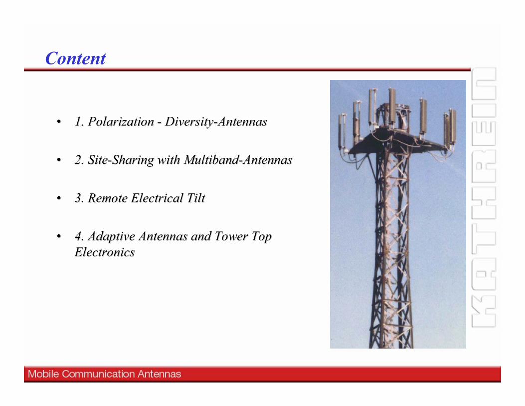
•• 1. Polarization 1. Polarization -- DiversityDiversity--AntennasAntennas
•• 2. Site2. Site--Sharing with Sharing with MultibandMultiband--AntennasAntennas
•• 3. Remote Electrical Tilt3. Remote Electrical Tilt
•• 4. Adaptive Antennas and Tower Top 4. Adaptive Antennas and Tower Top ElectronicsElectronics
Content
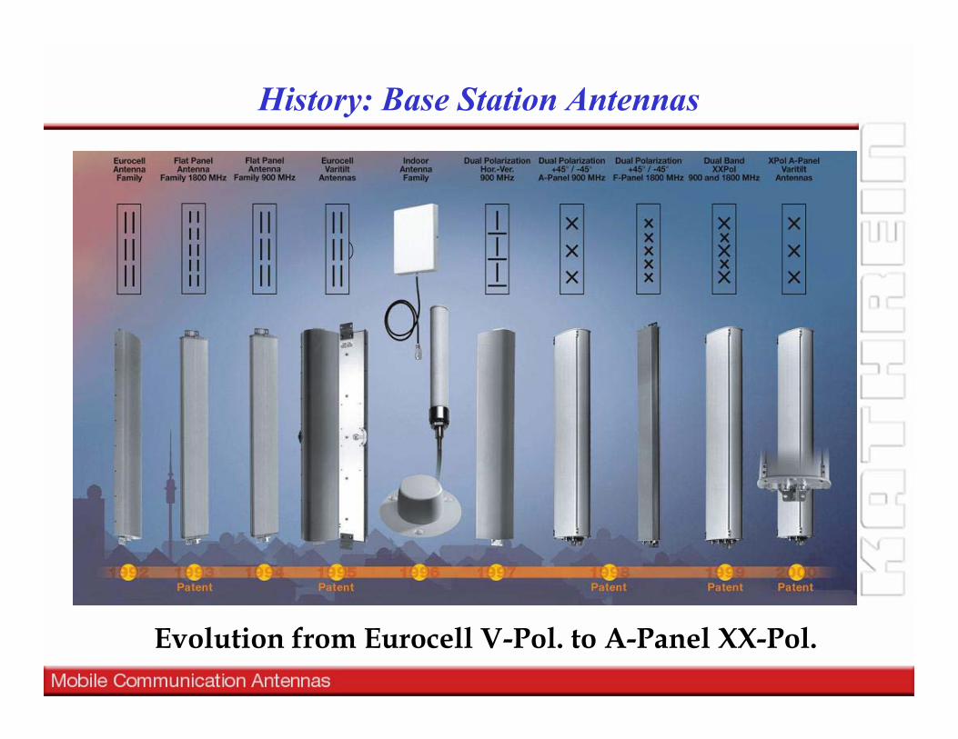
Evolution from Eurocell V-Pol. to A-Panel XX-Pol.
History: Base Station Antennas

1. Polarization Diversity Antennas

Diversity combining
Diversity with two antennas
-30
-25
-20
-15
-10
-5
0
5
10
1
Time
Sign
al L
evel
[dB
]
Rx 2Rx 1
Combined Signal
-30
-25
-20
-15
-10
-5
0
5
10
1
Time
Sign
al le
vel [
dB]
252321191715131197531
00.
20.
40.
60.
81
0
1
2
3
4
5
6
7
8
Div
ersi
ty G
ain
[dB
]
Signal Difference [dB]Cross-
Correlation
Maximal Ratio Combining
252321191715131197531
00.
20.
40.
60.
81
0
1
2
3
4
5
6
7
8
Div
ersi
ty G
ain
[dB
]
Signal Difference [dB]Cross-
Correlation
Maximal Ratio Combining
-- Level Level differencedifference-- CorrelationCorrelation
Diversity gain GSM Diversity gain GSM
Outage Probability (y<x)
1,E-04
1,E-03
1,E-02
1,E-01
1,E+00
-40 -30 -20 -10 0 10
10 log (x/Γ ) [dB]
Pr (
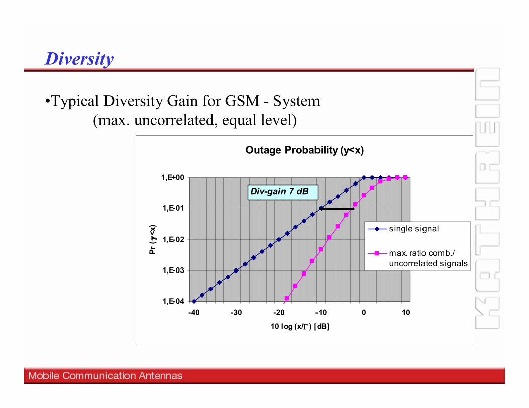
<x) single signal
max. ratio comb./uncorrelated signals
Div-gain 7 dB
Diversity
•Typical Diversity Gain for GSM - System (max. uncorrelated, equal level)
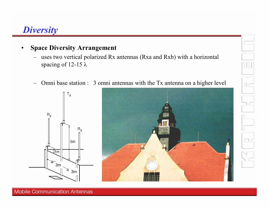
• Space Diversity Arrangement– uses two vertical polarized Rx antennas (Rxa and Rxb) with a horizontal
spacing of 12-15 λ
– Omni base station : 3 omni antennas with the Tx antenna on a higher level
3m3m
Diversity
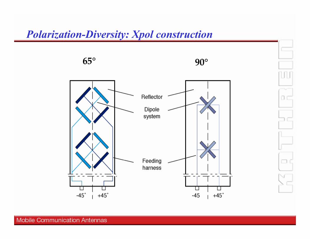
Polarization-Diversity: Xpol construction
65° 90°
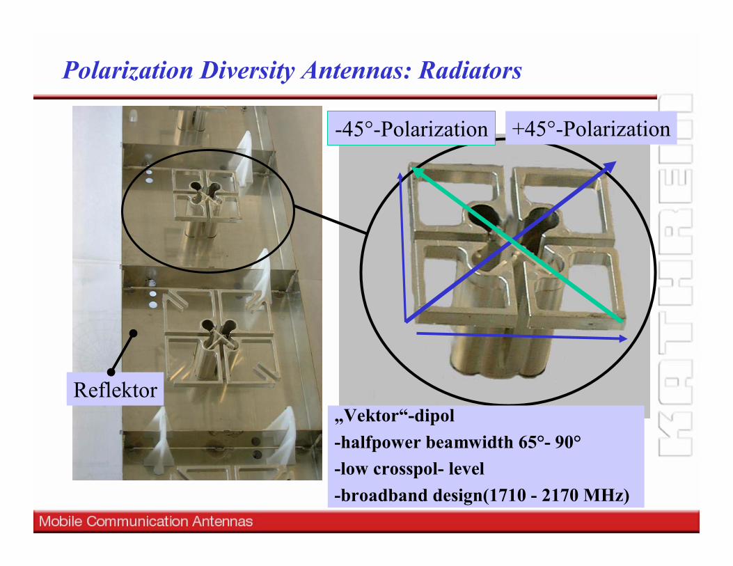
+45°-Polarization-45°-Polarization
Reflektor
Polarization Diversity Antennas: Radiators
„Vektor“-dipol -halfpower beamwidth 65°- 90° -low crosspol- level-broadband design(1710 - 2170 MHz)
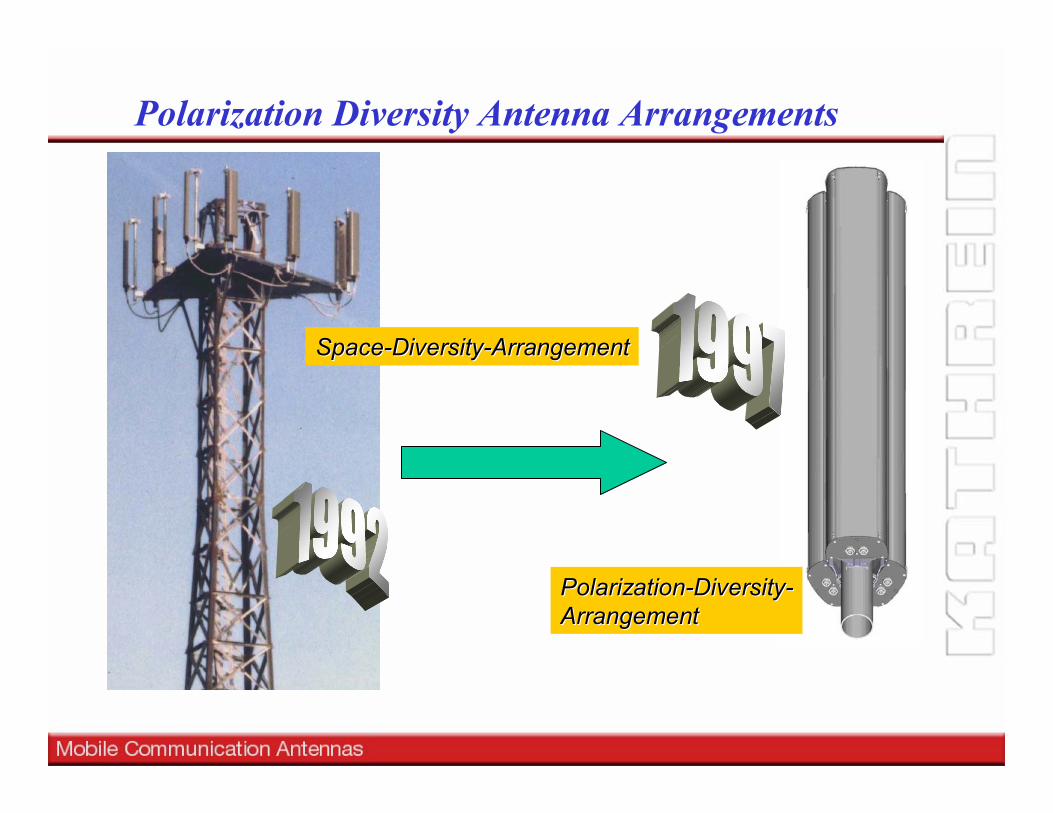
Polarization Diversity Antenna Arrangements
PolarizationPolarization--DiversityDiversity--ArrangementArrangement
SpaceSpace--DiversityDiversity--ArrangementArrangement
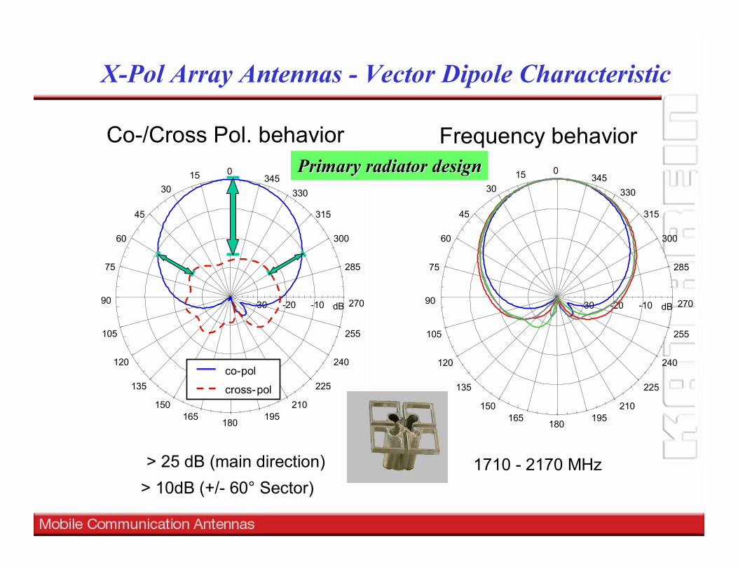
X-Pol Array Antennas - Vector Dipole Characteristic
01530
45
60
75
90
105
120
135
150165
180195
210
225
240
255
270
285
300
315
330345
-30 -20 -10 dB
co-pol
cross-pol
Co-/Cross Pol. behavior015
30
45
60
75
90
105
120
135
150165
180195
210
225
240
255
270
285
300
315
330345
-30 -20 -10 dB
Frequency behavior
1710 - 2170 MHz> 25 dB (main direction)> 10dB (+/- 60° Sector)
Primary radiator designPrimary radiator design
Site-Sharing with Dual and Triple-Band Antennas

Dualband Antennas / XXpol System
TETRA 380 - 430 MHzGSM 450 MHzDVB-H 512-860 MHzAMPS 824 - 890 MHzGSM 900 880-960 MHzGSM 1800 1710 - 1880 MHzUMTS 1920 - 2170 MHzUMTS LTE 2500 - 2700 MHzWiMax 3.4 - 3.8 GHz
Major Mobile Major Mobile Communication FrequenciesCommunication Frequencies

Site Sharing and Multi-Band Antennas
XXPol-Dual-Bandmit Combiner
Single-Band-Antennenfür GSM900 und GSM1800
GSM1800(E-Netz)
GSM900(D-Netz)
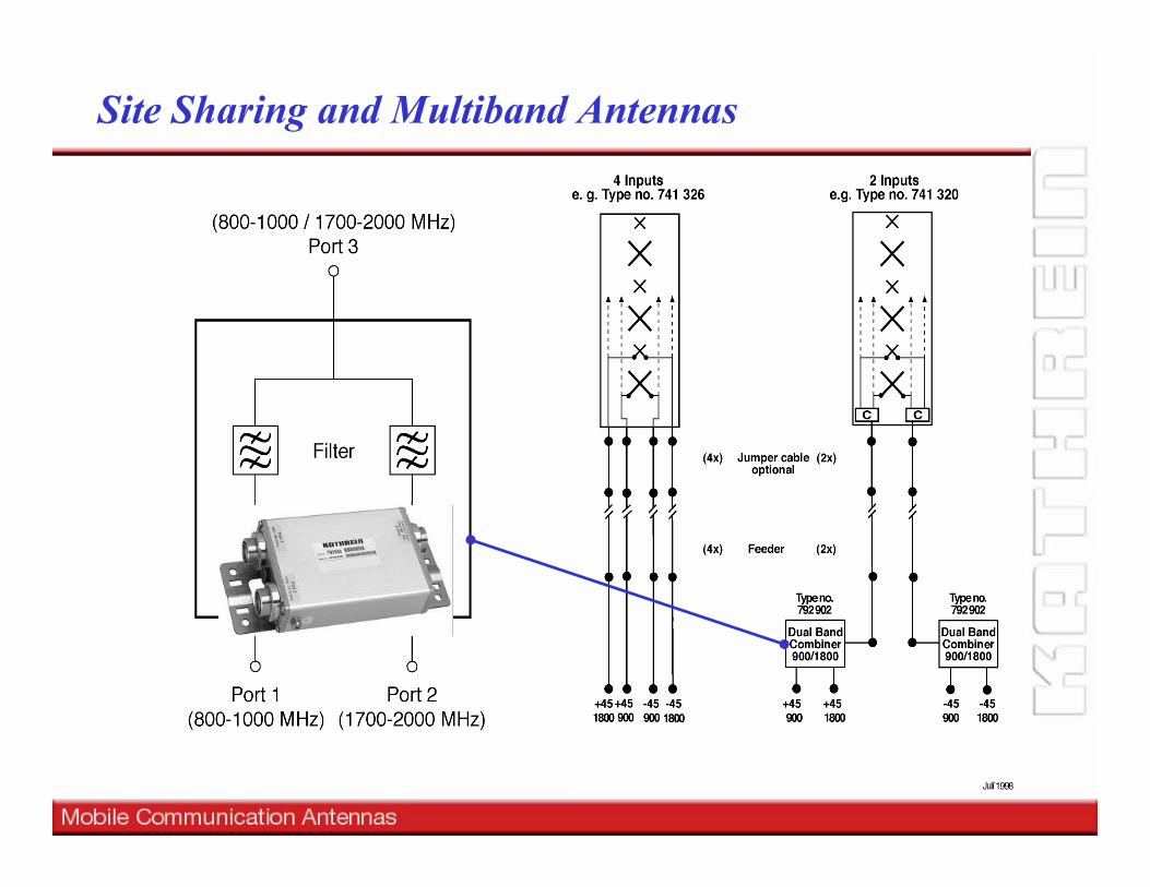
Site Sharing and Multiband Antennas
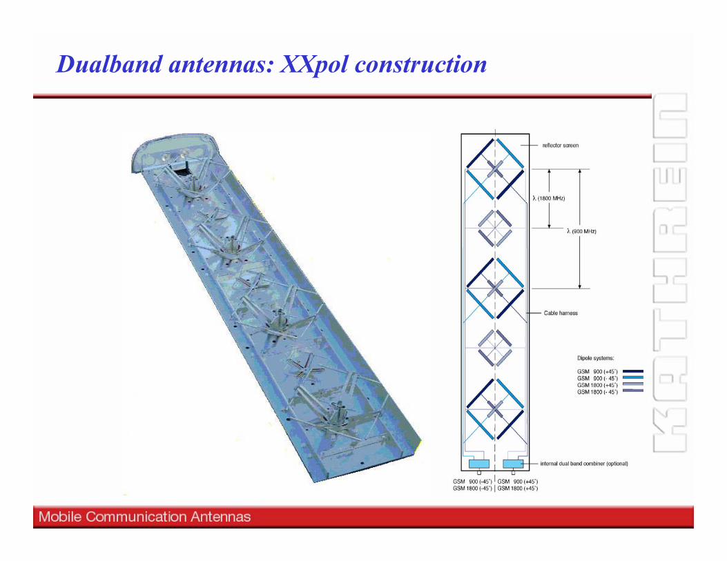
Dualband antennas: XXpol construction

Triple-Band Antennas
TETRA 380 - 430 MHzGSM 450 MHzDVB-H 512-860 MHzAMPS 824 - 890 MHzGSM 900 880-960 MHzGSM 1800 1710 - 1880 MHzUMTS 1920 - 2170 MHzUMTS LTE 2500 - 2700 MHzWiMax 3.4 - 3.8 GHz
Major Mobile Major Mobile Communication FrequenciesCommunication Frequencies
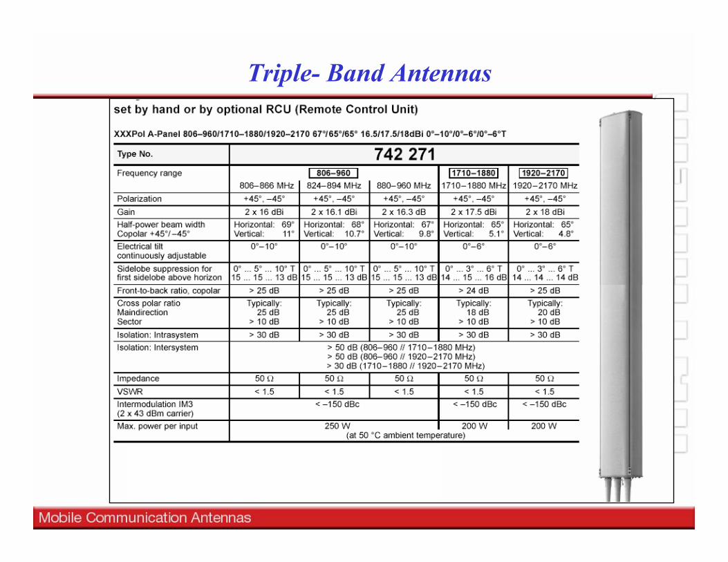
Independent adjustable Downtilt
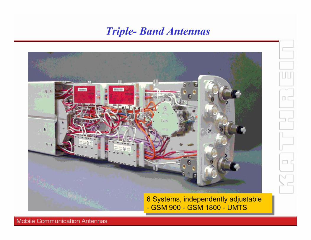
Triple- Band Antennas
6 Systems, independently adjustable- GSM 900 - GSM 1800 - UMTS
6 Systems, independently adjustable- GSM 900 - GSM 1800 - UMTS
Triple- Band Antennas
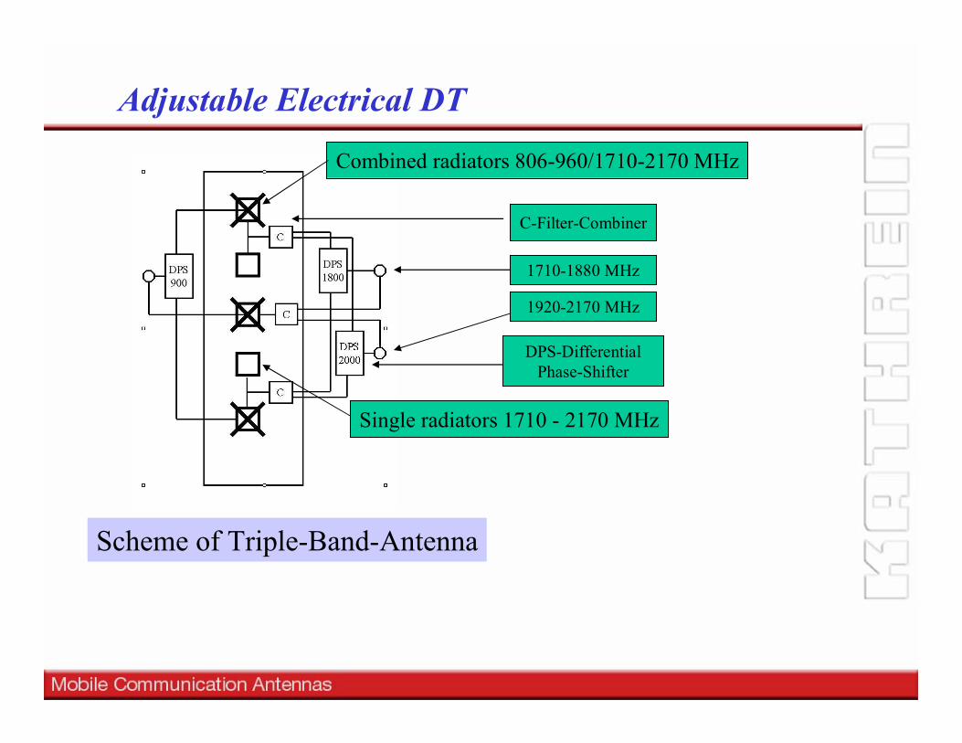
Scheme of Triple-Band-Antenna
Adjustable Electrical DT
C-Filter-Combiner
DPS-DifferentialPhase-Shifter
Combined radiators 806-960/1710-2170 MHz
Single radiators 1710 - 2170 MHz
1710-1880 MHz
1920-2170 MHz

2527293133353739414345
Isolation
0 1 2 3 4 5 6 7 8 9 100
2
4
6
Downtilt 900 MHz
Downtilt 1800 MHz
Isolation +/-45° Triple-Band-Antenna
frequencyfrequency
VSWRVSWR
Downtilt Downtilt GSM 1800GSM 1800
Sidelobe levelSidelobe level
isolationisolation
Crosspolar Crosspolar levellevel Halfpower Halfpower
beamwidthbeamwidth
TrackingTracking,,squintsquint
Downtilt Downtilt UMTSUMTS
Downtilt Downtilt GSM 900GSM 900
Complex design:Optimization Parameter of Triple-Band Antennas
Triple- Band Antennas
Remote Electrical Tilt
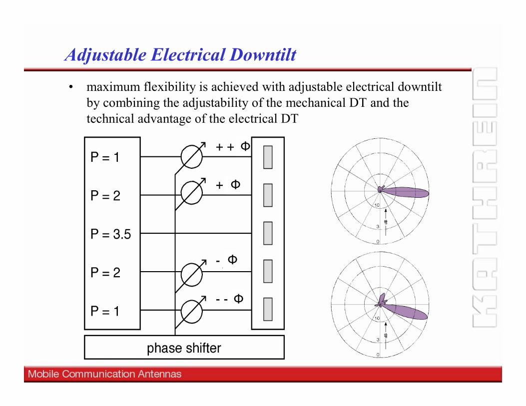
• maximum flexibility is achieved with adjustable electrical downtilt by combining the adjustability of the mechanical DT and the technical advantage of the electrical DT
Adjustable Electrical Downtilt
Ф
Ф
Ф
Ф

• Network Network Extension Extension •• Support of Support of traffic dependent cell breathing traffic dependent cell breathing and and regulation regulation of softof soft--
Handover areasHandover areas•• Hot Hot spots during special eventsspots during special events•• Dynamical traffic Dynamical traffic adaptive adaptive regulation regulation of of cell load cell load
Adjustable Electrical Downtilt
High trafficarea„Hot Spot“
„Cell Brathing“
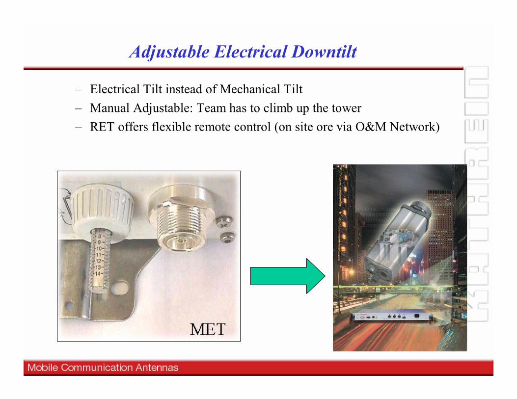
– Electrical Tilt instead of Mechanical Tilt– Manual Adjustable: Team has to climb up the tower– RET offers flexible remote control (on site ore via O&M Network)
Adjustable Electrical Downtilt
RET
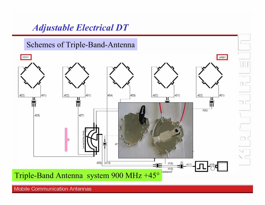
Adjustable Electrical DT
Triple-Band Antenna system 900 MHz +45°
Schemes of Triple-Band-Antenna
Passive Differential Phase Shifter
Schemes of Triple-Band-Antenna
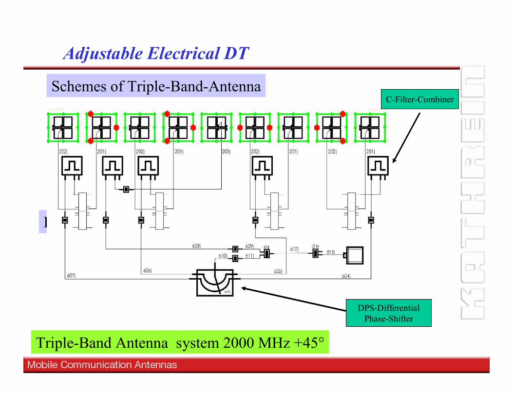
Adjustable Electrical DT
DPS-DifferentialPhase-Shifter
Triple-Band Antenna system 2000 MHz +45°
C-Filter-Combiner
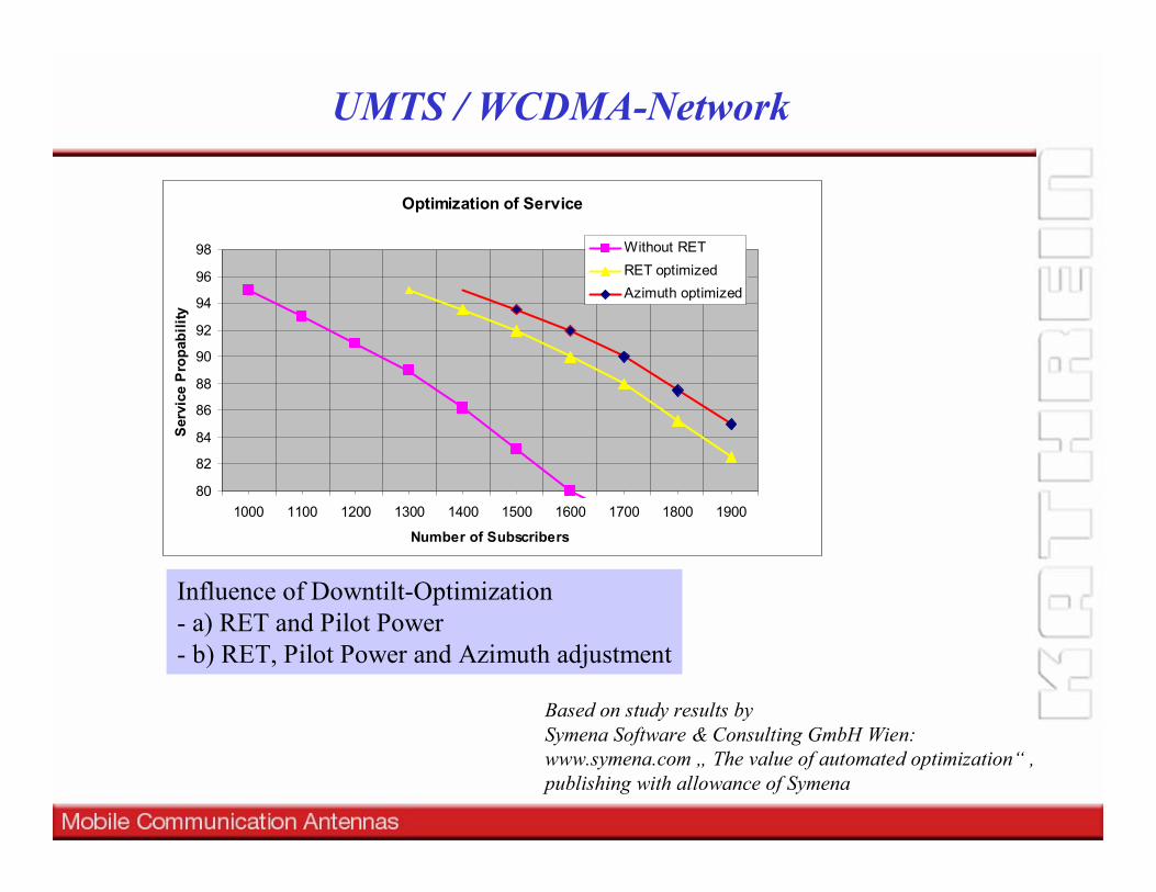
Influence of Downtilt-Optimization- a) RET and Pilot Power - b) RET, Pilot Power and Azimuth adjustment
Based on study results by Symena Software & Consulting GmbH Wien:www.symena.com „ The value of automated optimization“ ,publishing with allowance of Symena
UMTS / WCDMA-Network
Optimization of Service
80
82
84
86
88
90
92
94
96
98
1000 1100 1200 1300 1400 1500 1600 1700 1800 1900
Number of Subscribers
Serv
ice
Pro
pabi
lity
Without RETRET optimizedAzimuth optimized
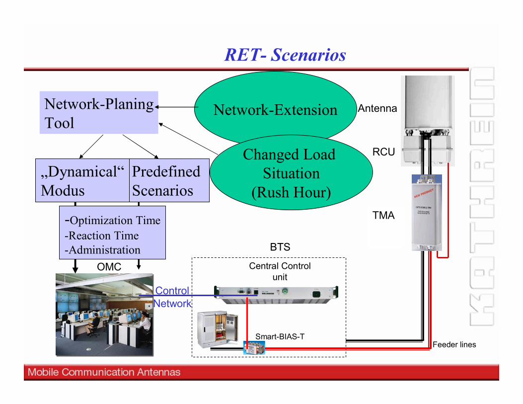
Smart-BIAS-T
RET- Scenarios
OMC
BTS
Central Controlunit
RCU
Antenna
Feeder lines
TMA
Network-PlaningTool
Network-Extension
Changed Load Situation
(Rush Hour)Predefined Scenarios
ControlNetwork
„Dynamical“Modus
-Optimization Time-Reaction Time-Administration
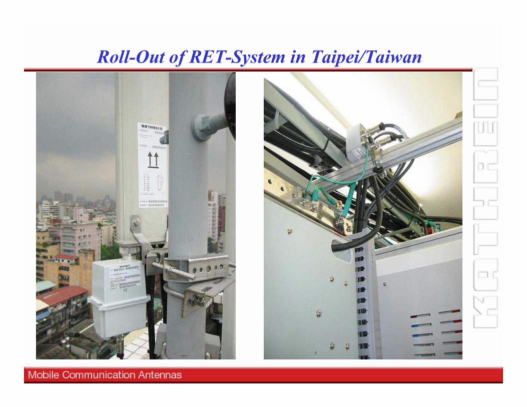
Roll-Out of RET-System in Taipei/Taiwan

Adaptive Antennas and Tower Top Electronics

Adaptive Antennas
Transmit the power to the correct destination.
Antennas with beam-forming:
- "SMART" - Antennas- „Multi-Beam“-Antennas- Adaptive Antennas
Antennas with beamAntennas with beam--forming:forming:
-- "SMART" "SMART" -- AntennasAntennas-- „Multi„Multi--Beam“Beam“--AntennasAntennas-- Adaptive AntennasAdaptive Antennas
- Increased Capacity- Reduced interference level- Reduced Transmit-Power- Reduction of average EM
fieldsbut
-Expensive BTS-n x Feeder Cables-Higher Size- Reduced Site Sharing Capabilities
-- Increased CapacityIncreased Capacity-- Reduced interference levelReduced interference level-- Reduced TransmitReduced Transmit--PowerPower-- Reduction of average EMReduction of average EM
fieldsfieldsbutbut
--Expensive BTSExpensive BTS--n x Feeder Cablesn x Feeder Cables--Higher SizeHigher Size-- Reduced Site Sharing CapabilitiesReduced Site Sharing Capabilities

Adaptive Antennas - Control principles
Adaptive AntennaControl Options
Standard BTS
Control via:-Handover (Switched) -Soft Handover (Makro-
Diversity)
Special BTS for n Sensors
Beam-Forming Algorithm-Switched fixed beam-MRC principle
2X...4X array antennasoption: flat frequency phase-dependency for FDD
-2X...4X dual beam antennas-common 6-sector arrangements
-Backbone network takes over high traffic -or increased handovers required
Pilot carrier (BCCH) has to been distributed within the whole cell
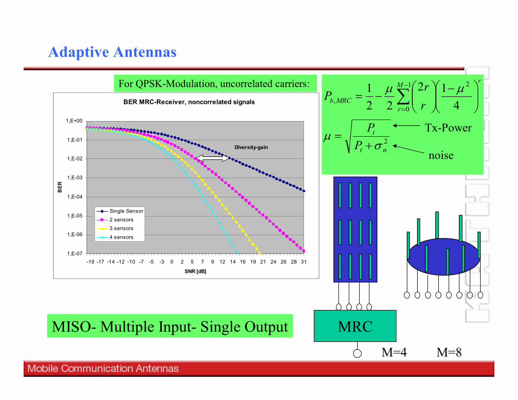
BER MRC-Receiver, noncorrelated signals
1,E-07
1,E-06
1,E-05
1,E-04
1,E-03
1,E-02
1,E-01
1,E+00
31282624211916141297520-3-5-7-10-12-14-17-19
SNR [dB]
BER
Single Sensor2 sensors3 sensors
4 sensors
Diversity-gain
Adaptive Antennas
M=4 M=8
2
21
0, 4
1222
1
nt
t
rM
rMRCb
PP
rr
P
σµ
µµ
+=
−
−= ∑
−
=
noise
Tx-Power
For QPSK-Modulation, uncorrelated carriers:
MISO- Multiple Input- Single Output MRC
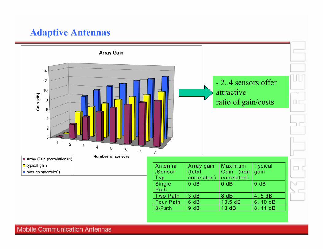
1 2 3 4 5 6 7 8
0
2
4
6
8
10
12
14
Gai
n [d
B]
Number of sensors
Array Gain
Array Gain (correlation=1)typical gainmax gain(correl=0)
Antenna/SensorTyp
Array gain(totalcorrelated)
Maxim umGain (noncorrelated)
Typicalgain
SinglePath
0 dB 0 dB 0 dB
Two Path 3 dB 8 dB 4..5 dBFour Path 6 dB 10.5 dB 6..10 dB8-Path 9 dB 13 dB 8..11 dB
- 2..4 sensors offer attractiveratio of gain/costs
Adaptive Antennas
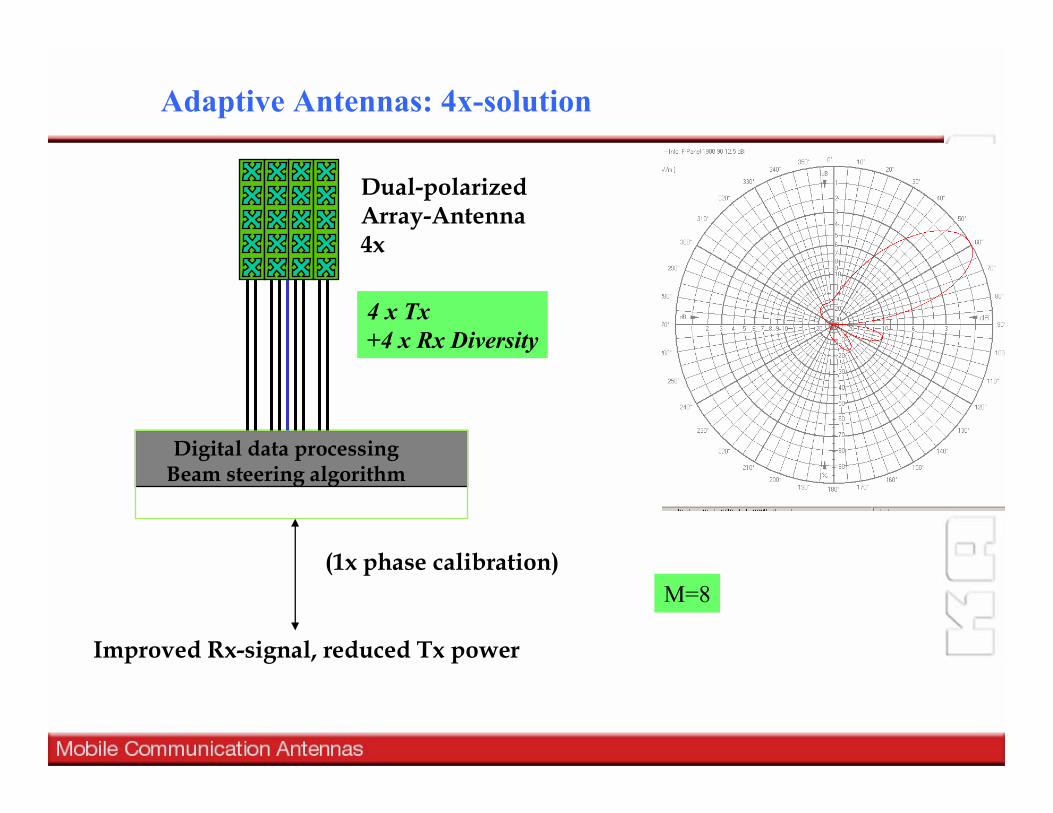
Adaptive Antennas: 4x-solution
Improved Rx-signal, reduced Tx power
Digital data processingBeam steering algorithm
Dual-polarizedArray-Antenna 4x
(1x phase calibration)M=8
4 x Tx+4 x Rx Diversity
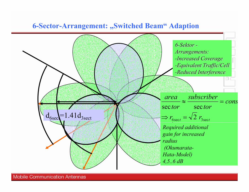
6-Sector-Arrangement: „Switched Beam“ Adaption
66--Sektor Sektor --Arrangements:Arrangements:--Increased CoverageIncreased Coverage--Equivalent TrafficEquivalent Traffic//CellCell--Reduced InterferenceReduced Interference
d6sect=1.41d3sect
Required additional gain for increasedradius(Okumarata-
Hata-Model)4,5..6 dB
tt rr
constor
subscribertor
area
sec3sec6 2secsec
=⇒
=≈

path loss
80
90
100
110
120
130
140
0,1 0,3 0,5 0,7 0,9 1,1 1,3 1,5 1,7 1,9
Distance [km]
Path
loss
[dB] h= 10 m
h=20mh=40mh=100m
Increased coverage
f=2GHz, gTx=18 dBi, Okumurata-Hata
Increased Coverage due to increased height of the Tx Antenna
„Ultra High sites“
∆h
6-Sector Ultra High sites

Dual-Beam-Antenna ( 2 Columns)
Adaptive Antenna: Dual Beam (2X)
3dB-Hybrid
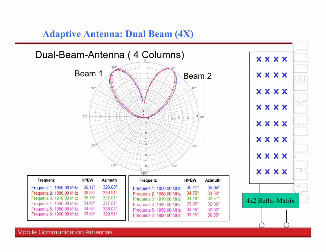
Frequenz HPBW Azimuth
Frequenz HPBW Azimuth
Beam 1 Beam 2
Adaptive Antenna: Dual Beam (4X)
4x2 Butler-Matrix
Dual-Beam-Antenna ( 4 Columns)
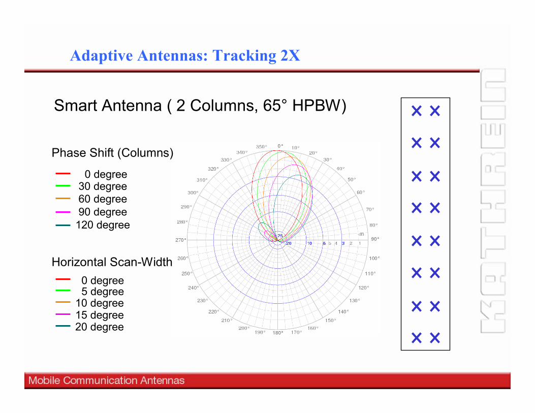
Smart Antenna ( 2 Columns, 65° HPBW)
Horizontal Scan-Width0 degree5 degree
10 degree15 degree20 degree
Phase Shift (Columns)
0 degree30 degree60 degree90 degree
120 degree
Adaptive Antennas: Tracking 2X
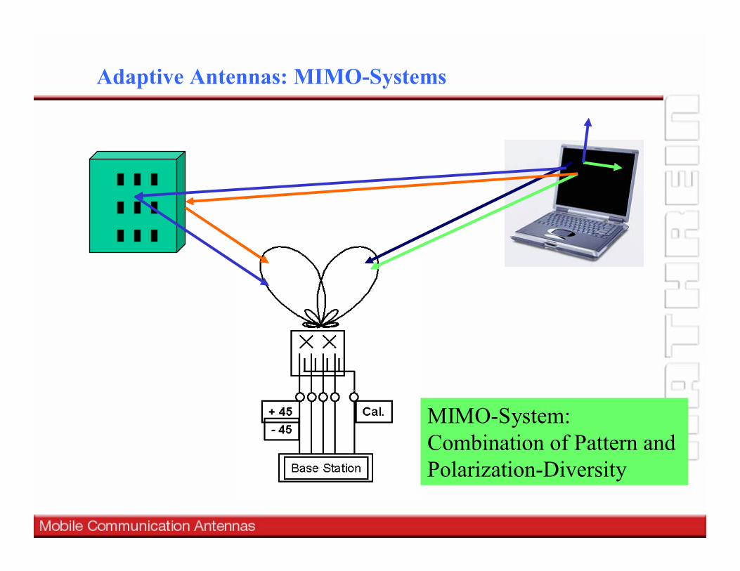
MIMO-System:Combination of Pattern and Polarization-Diversity
Adaptive Antennas: MIMO-Systems
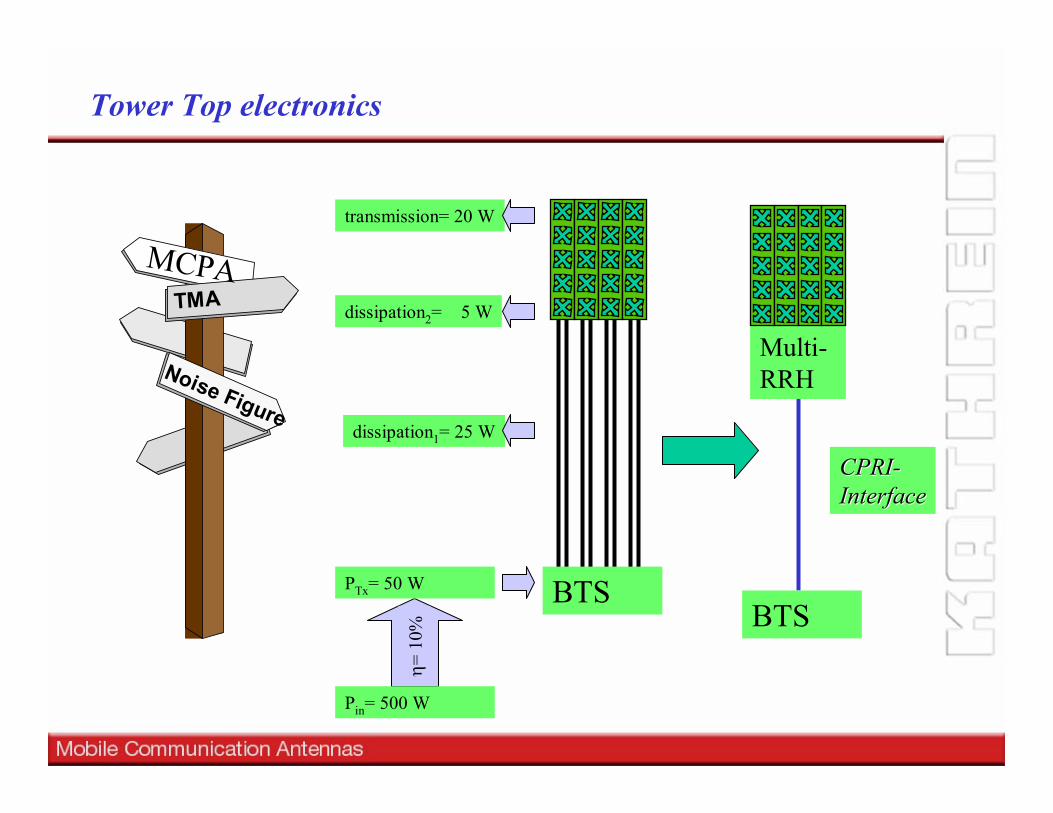
Tower Top electronics
TMA
Noise Figure
MCPA
BTSBTS
Multi-RRH
CPRICPRI--InterfaceInterface
PTx= 50 W
dissipation1= 25 W
dissipation2= 5 W
transmission= 20 W
Pin= 500 W
η= 1
0%
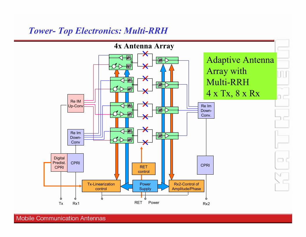
Tx-Linearizationcontrol
Rx2Tx Rx1
Re IMUp-Conv
Re ImDown-Conv
Re ImDown-Conv.
Rx2-Control ofAmplitude/Phase
PowerSupply
PowerRET
DigitalPredist.CPRI
CPRI CPRI
Adaptive AntennaArray with Multi-RRH4 x Tx, 8 x Rx
RET control
4x Antenna Array
Tower- Top Electronics: Multi-RRH


![and Samuel St ephan arXiv:2107.07206v1 [q-fin.ST] 15 Jul 2021](https://img.pdfslide.us/doc/110x75/61e14b0e37cce4645b4b34a1/and-samuel-st-ephan-arxiv210707206v1-q-finst-15-jul-2021.jpg)