Embed Size (px)
Citation preview
Base Station Analyzer
© 2011 JDS Uniphase Corporation | JDSU CONFIDENTIAL AND PROPRIETARY INFORMATION
1. Descripción general del equipo.
2. Navegación y descripción de los diferentes modos:
– Medidor de Potencia.
– Analizador de Cable y Antena.
– Pruebas Ethernet.
– Analizador de Espectro.
– Analizador de Señales- Demodulación, Análisis OTA, Identificar KPIs.
• GSM
• WCDMA
• LTE
– Escáner de Canales.
– Software de Post-proceso.
– Carga y descarga de datos/configuraciones.
3. Generación de una rutina de prueba.
MODULO 1: TEORÍA
© 2011 JDS Uniphase Corporation | JDSU CONFIDENTIAL AND PROPRIETARY INFORMATION
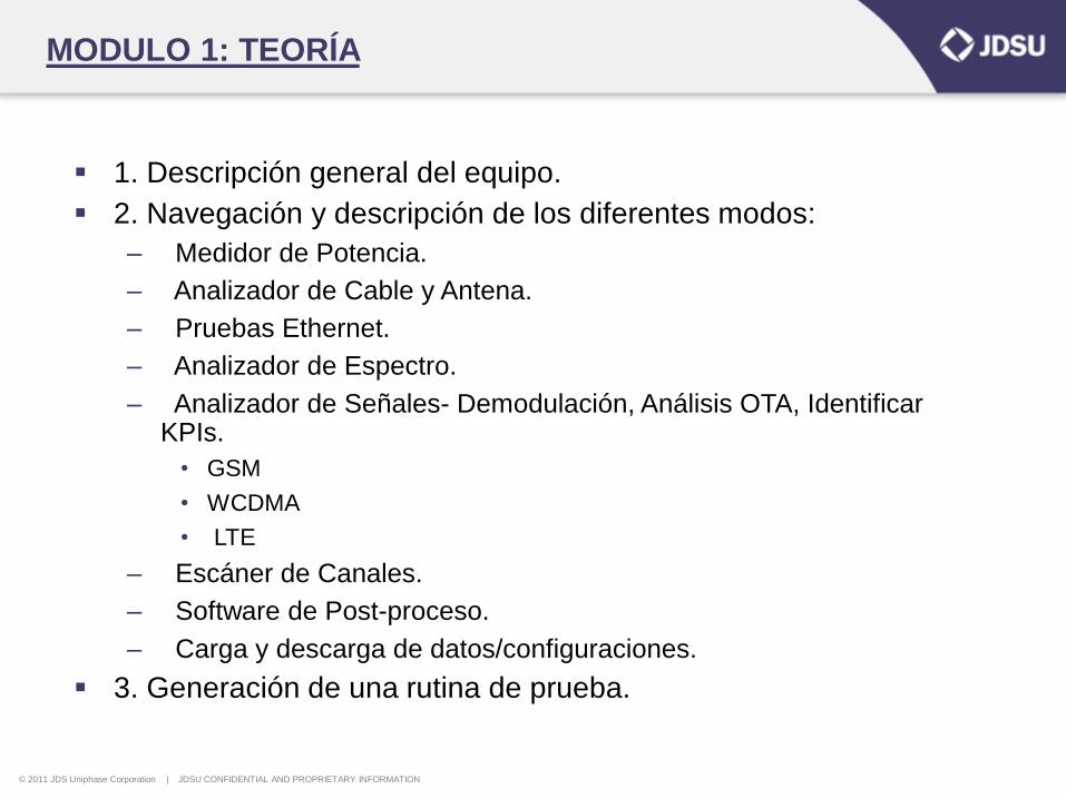
1. Descripción general del equipo.
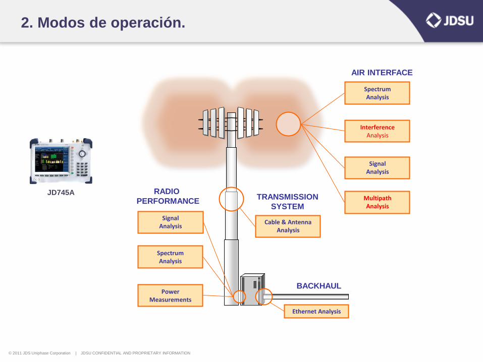
BACKHAUL
Ethernet Analysis
TRANSMISSION
SYSTEM
Cable & Antenna Analysis
AIR INTERFACE
Signal Analysis
Spectrum Analysis
Interference Analysis
Multipath Analysis
RADIO
PERFORMANCE
Power Measurements
Signal Analysis
Spectrum Analysis
JD745A
© 2011 JDS Uniphase Corporation | JDSU CONFIDENTIAL AND PROPRIETARY INFORMATION
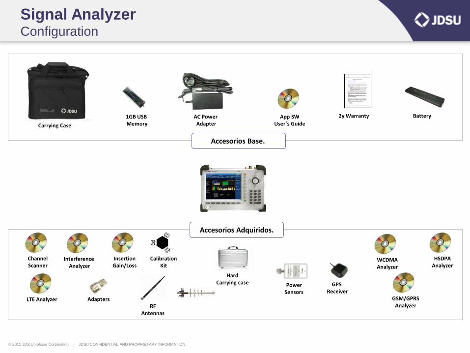
Signal Analyzer Configuration
Channel Scanner
Interference Analyzer
Insertion Gain/Loss
WCDMA Analyzer
HSDPA Analyzer
GSM/GPRS Analyzer
Calibration Kit
GPS Receiver
RF Antennas
Accesorios Base.
Hard Carrying case
Carrying Case
1GB USB Memory
AC Power Adapter
App SW User’s Guide
Battery 2y Warranty
Power Sensors
LTE Analyzer
Accesorios Adquiridos.
Adapters
© 2011 JDS Uniphase Corporation | JDSU CONFIDENTIAL AND PROPRIETARY INFORMATION
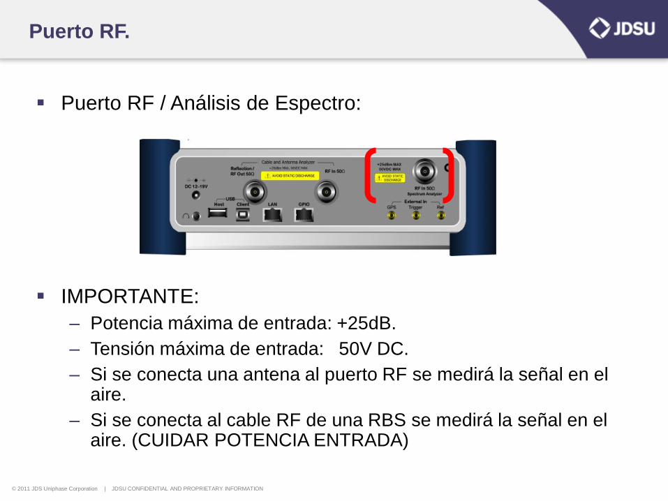
Puerto RF.
Puerto RF / Análisis de Espectro:
IMPORTANTE:
– Potencia máxima de entrada: +25dB.
– Tensión máxima de entrada: 50V DC.
– Si se conecta una antena al puerto RF se medirá la señal en el aire.
– Si se conecta al cable RF de una RBS se medirá la señal en el aire. (CUIDAR POTENCIA ENTRADA)
© 2011 JDS Uniphase Corporation | JDSU CONFIDENTIAL AND PROPRIETARY INFORMATION
2. Modos de operación.
BACKHAUL
Ethernet Analysis
TRANSMISSION
SYSTEM
Cable & Antenna Analysis
AIR INTERFACE
Signal Analysis
Spectrum Analysis
Interference Analysis
Multipath Analysis
RADIO
PERFORMANCE
Power Measurements
Signal Analysis
Spectrum Analysis
JD745A
© 2011 JDS Uniphase Corporation | JDSU CONFIDENTIAL AND PROPRIETARY INFORMATION
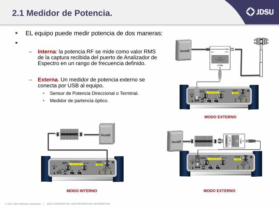
2.1 Medidor de Potencia.
EL equipo puede medir potencia de dos maneras:
– Interna: la potencia RF se mide como valor RMS de la captura recibida del puerto de Analizador de Espectro en un rango de frecuencia definido.
– Externa. Un medidor de potencia externo se conecta por USB al equipo.
• Sensor de Potencia Direccional o Terminal.
• Medidor de partencia óptico.
MODO EXTERNO
MODO EXTERNO MODO INTERNO
© 2011 JDS Uniphase Corporation | JDSU CONFIDENTIAL AND PROPRIETARY INFORMATION
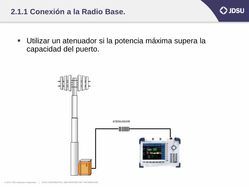
2.1.1 Conexión a la Radio Base.
Utilizar un atenuador si la potencia máxima supera la capacidad del puerto.
ATENUADOR
© 2011 JDS Uniphase Corporation | JDSU CONFIDENTIAL AND PROPRIETARY INFORMATION
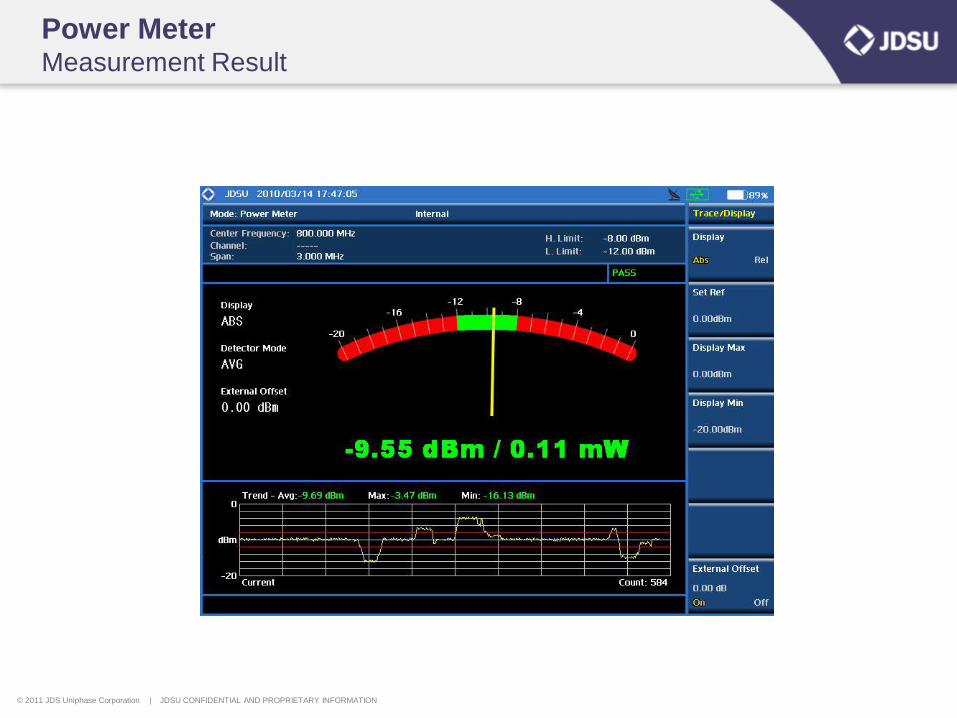
Power Meter Measurement Result
© 2011 JDS Uniphase Corporation | JDSU CONFIDENTIAL AND PROPRIETARY INFORMATION
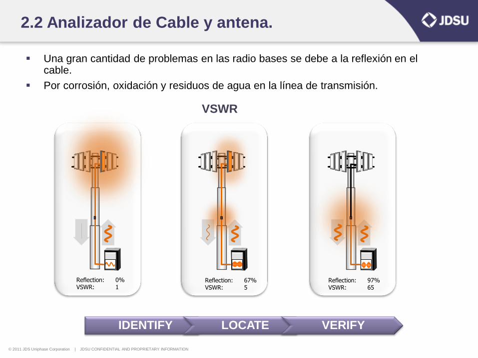
2.2 Analizador de Cable y antena.
Una gran cantidad de problemas en las radio bases se debe a la reflexión en el cable.
Por corrosión, oxidación y residuos de agua en la línea de transmisión.
Reflection: 0% VSWR: 1
Reflection: 67% VSWR: 5
Reflection: 97% VSWR: 65
IDENTIFY LOCATE VERIFY
VSWR
© 2011 JDS Uniphase Corporation | JDSU CONFIDENTIAL AND PROPRIETARY INFORMATION
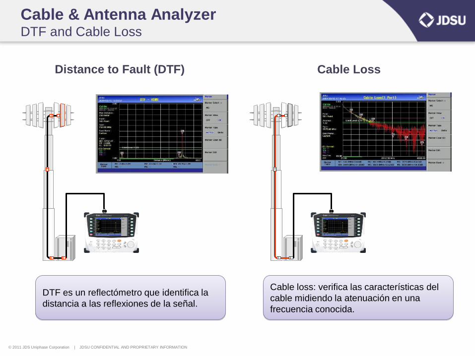
Cable & Antenna Analyzer DTF and Cable Loss
Distance to Fault (DTF) Cable Loss
DTF es un reflectómetro que identifica la
distancia a las reflexiones de la señal.
Cable loss: verifica las características del
cable midiendo la atenuación en una
frecuencia conocida.
© 2011 JDS Uniphase Corporation | JDSU CONFIDENTIAL AND PROPRIETARY INFORMATION
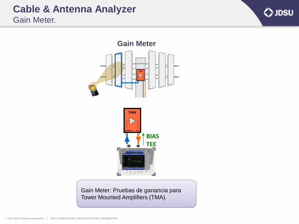
Cable & Antenna Analyzer Gain Meter.
TMA
BTSANTENNA
LNA
BIAS TEE
TMA
BTSANTENNA
LNA
Gain Meter: Pruebas de ganancia para
Tower Mounted Amplifiers (TMA).
Gain Meter
© 2011 JDS Uniphase Corporation | JDSU CONFIDENTIAL AND PROPRIETARY INFORMATION
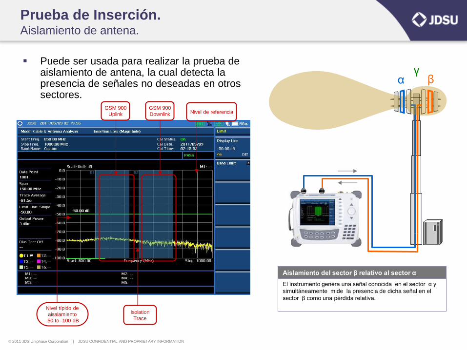
Prueba de Inserción. Aislamiento de antena.
Puede ser usada para realizar la prueba de aislamiento de antena, la cual detecta la presencia de señales no deseadas en otros sectores.
GSM 900
Uplink
GSM 900
Downlink
Isolation
Trace
α γ
β
Aislamiento del sector β relativo al sector α
Nivel de referencia
El instrumento genera una señal conocida en el sector α y
simultáneamente mide la presencia de dicha señal en el
sector β como una pérdida relativa.
Nivel típido de
aisalamiento
-50 to -100 dB
© 2011 JDS Uniphase Corporation | JDSU CONFIDENTIAL AND PROPRIETARY INFORMATION
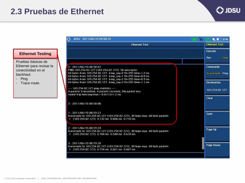
2.3 Pruebas de Ethernet
Pruebas básicas de
Ethernet para revisar la
conectividad en el
backhaul.
- Ping
- Trace-route.
Ethernet Testing
© 2011 JDS Uniphase Corporation | JDSU CONFIDENTIAL AND PROPRIETARY INFORMATION
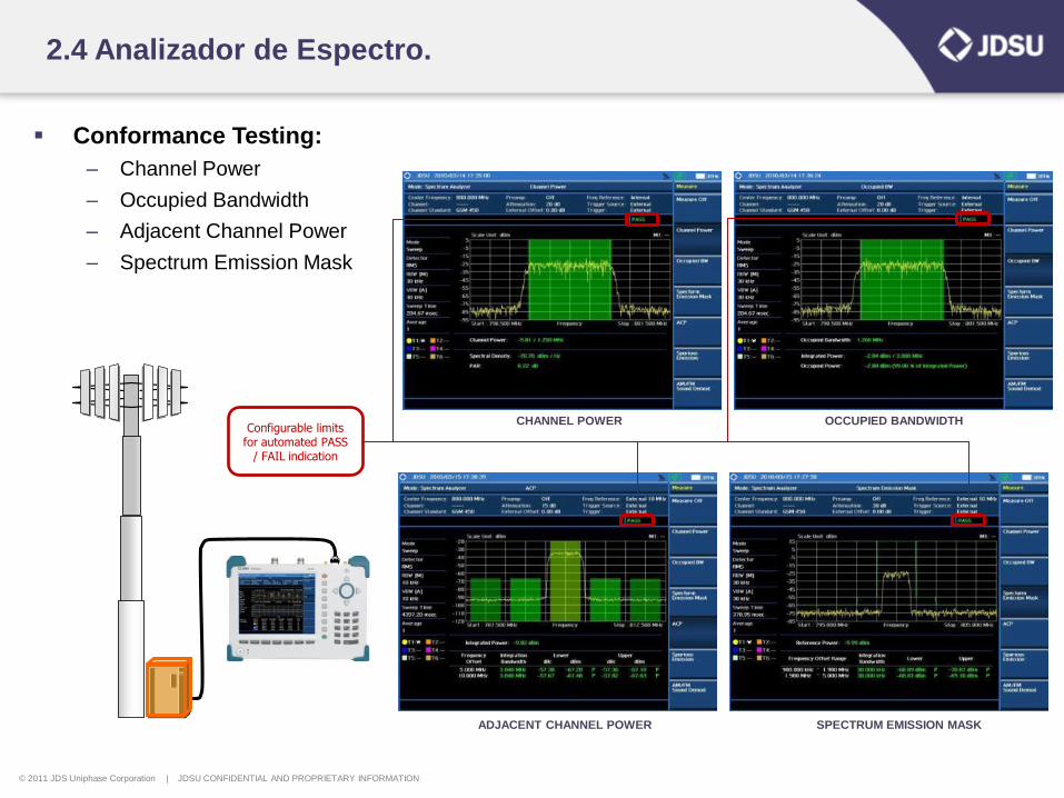
2.4 Analizador de Espectro.
Conformance Testing:
– Channel Power
– Occupied Bandwidth
– Adjacent Channel Power
– Spectrum Emission Mask
OCCUPIED BANDWIDTH CHANNEL POWER
ADJACENT CHANNEL POWER SPECTRUM EMISSION MASK
Configurable limits for automated PASS
/ FAIL indication
© 2011 JDS Uniphase Corporation | JDSU CONFIDENTIAL AND PROPRIETARY INFORMATION
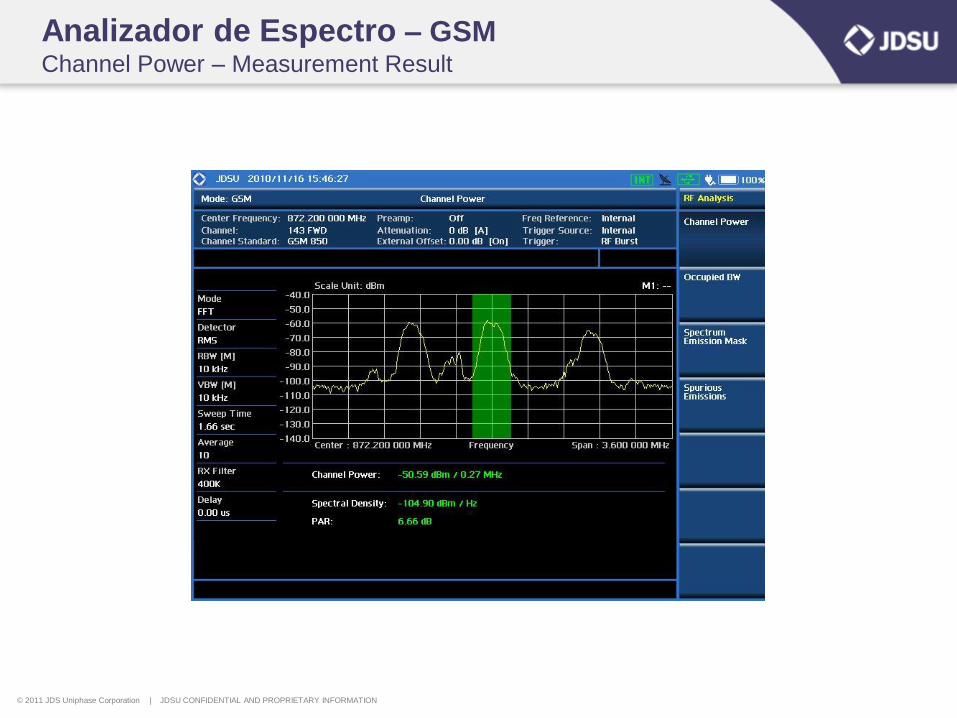
Analizador de Espectro – GSM Channel Power – Measurement Result
© 2011 JDS Uniphase Corporation | JDSU CONFIDENTIAL AND PROPRIETARY INFORMATION
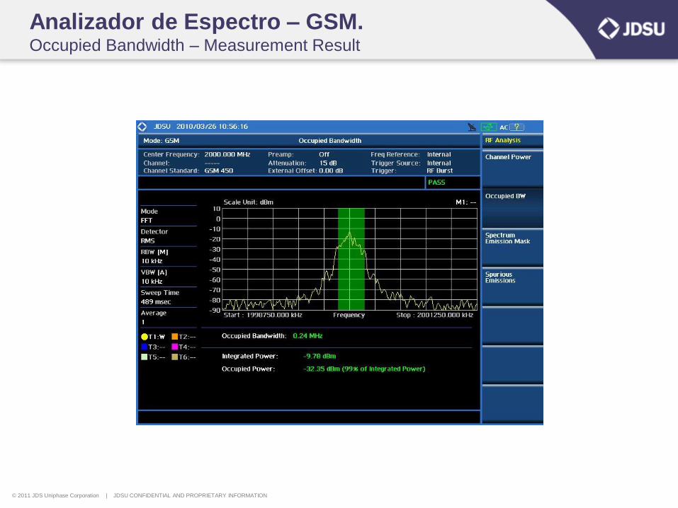
Analizador de Espectro – GSM. Occupied Bandwidth – Measurement Result
© 2011 JDS Uniphase Corporation | JDSU CONFIDENTIAL AND PROPRIETARY INFORMATION
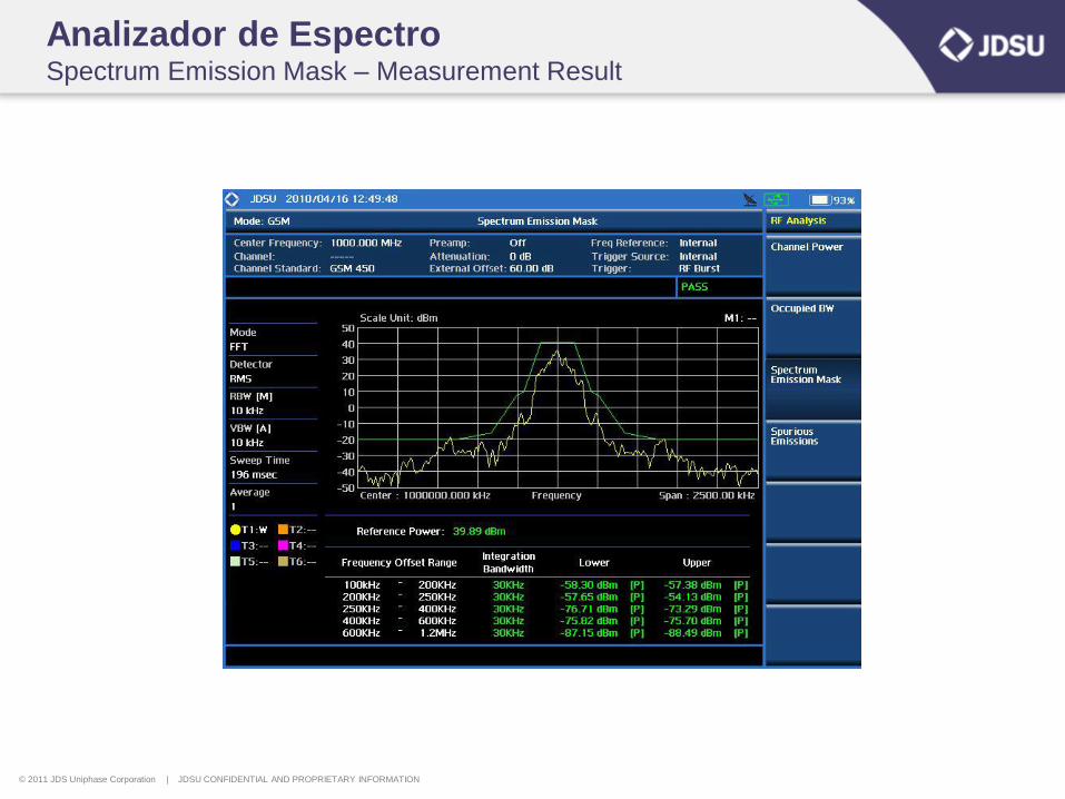
Analizador de Espectro Spectrum Emission Mask – Measurement Result
© 2011 JDS Uniphase Corporation | JDSU CONFIDENTIAL AND PROPRIETARY INFORMATION
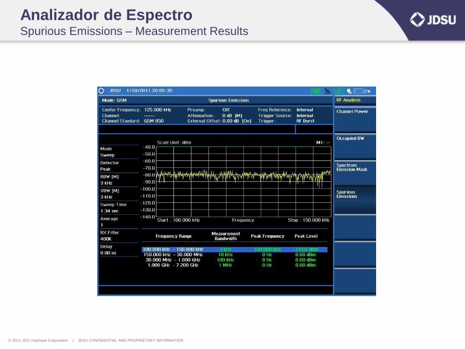
Analizador de Espectro Spurious Emissions – Measurement Results
© 2011 JDS Uniphase Corporation | JDSU CONFIDENTIAL AND PROPRIETARY INFORMATION
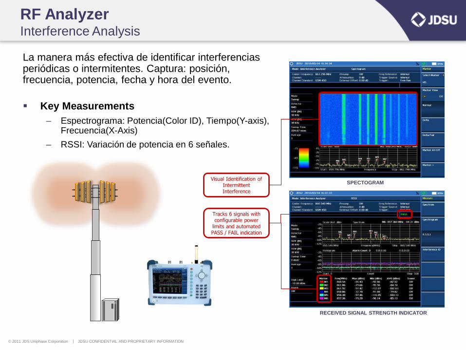
RF Analyzer Interference Analysis
La manera más efectiva de identificar interferencias periódicas o intermitentes. Captura: posición, frecuencia, potencia, fecha y hora del evento.
Key Measurements
– Espectrograma: Potencia(Color ID), Tiempo(Y-axis), Frecuencia(X-Axis)
– RSSI: Variación de potencia en 6 señales.
SPECTOGRAM
RECEIVED SIGNAL STRENGTH INDICATOR
Tracks 6 signals with configurable power
limits and automated PASS / FAIL indication
Visual Identification of Intermittent Interference
© 2011 JDS Uniphase Corporation | JDSU CONFIDENTIAL AND PROPRIETARY INFORMATION
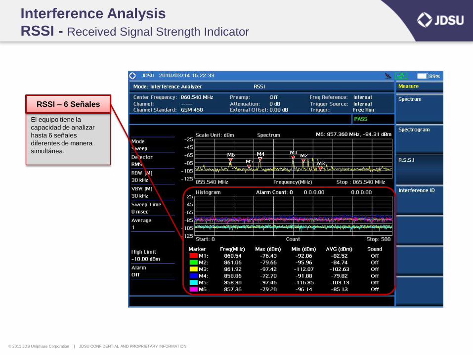
Interference Analysis
RSSI - Received Signal Strength Indicator
El equipo tiene la
capacidad de analizar
hasta 6 señales
diferentes de manera
simultánea.
RSSI – 6 Señales
© 2011 JDS Uniphase Corporation | JDSU CONFIDENTIAL AND PROPRIETARY INFORMATION
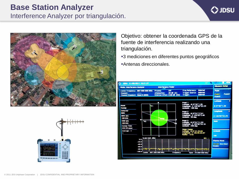
Base Station Analyzer Interference Analyzer por triangulación.
Objetivo: obtener la coordenada GPS de la
fuente de interferencia realizando una
triangulación.
3 mediciones en diferentes puntos geográficos
Antenas direccionales.
© 2011 JDS Uniphase Corporation | JDSU CONFIDENTIAL AND PROPRIETARY INFORMATION
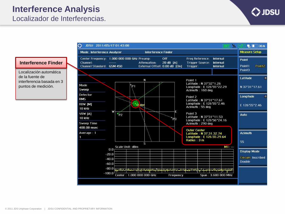
Interference Analysis Localizador de Interferencias.
Localización automática
de la fuente de
interferencia basada en 3
puntos de medición.
Interference Finder
© 2011 JDS Uniphase Corporation | JDSU CONFIDENTIAL AND PROPRIETARY INFORMATION
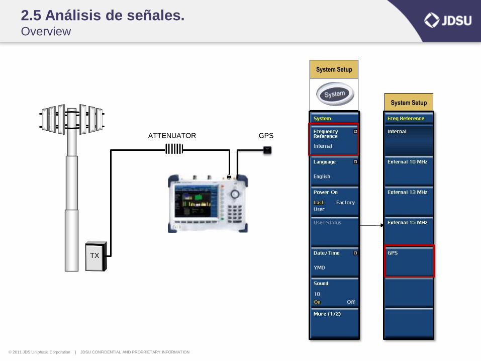
2.5 Análisis de señales. Overview
System Setup
ATTENUATOR
TX
GPS
System Setup
© 2011 JDS Uniphase Corporation | JDSU CONFIDENTIAL AND PROPRIETARY INFORMATION
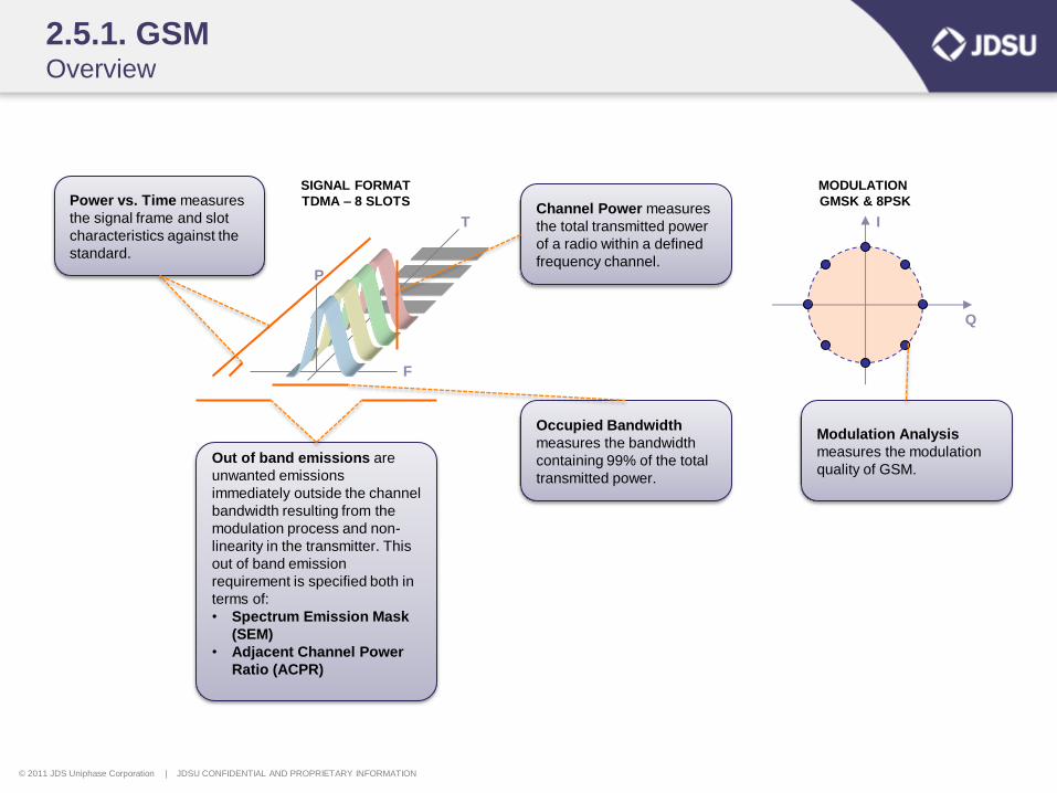
2.5.1. GSM Overview
SIGNAL FORMAT
TDMA – 8 SLOTS
F
P
T I
Q
MODULATION
GMSK & 8PSK Channel Power measures
the total transmitted power
of a radio within a defined
frequency channel.
Occupied Bandwidth
measures the bandwidth
containing 99% of the total
transmitted power.
Out of band emissions are
unwanted emissions
immediately outside the channel
bandwidth resulting from the
modulation process and non-
linearity in the transmitter. This
out of band emission
requirement is specified both in
terms of:
• Spectrum Emission Mask
(SEM)
• Adjacent Channel Power
Ratio (ACPR)
Modulation Analysis
measures the modulation
quality of GSM.
Power vs. Time measures
the signal frame and slot
characteristics against the
standard.
© 2011 JDS Uniphase Corporation | JDSU CONFIDENTIAL AND PROPRIETARY INFORMATION
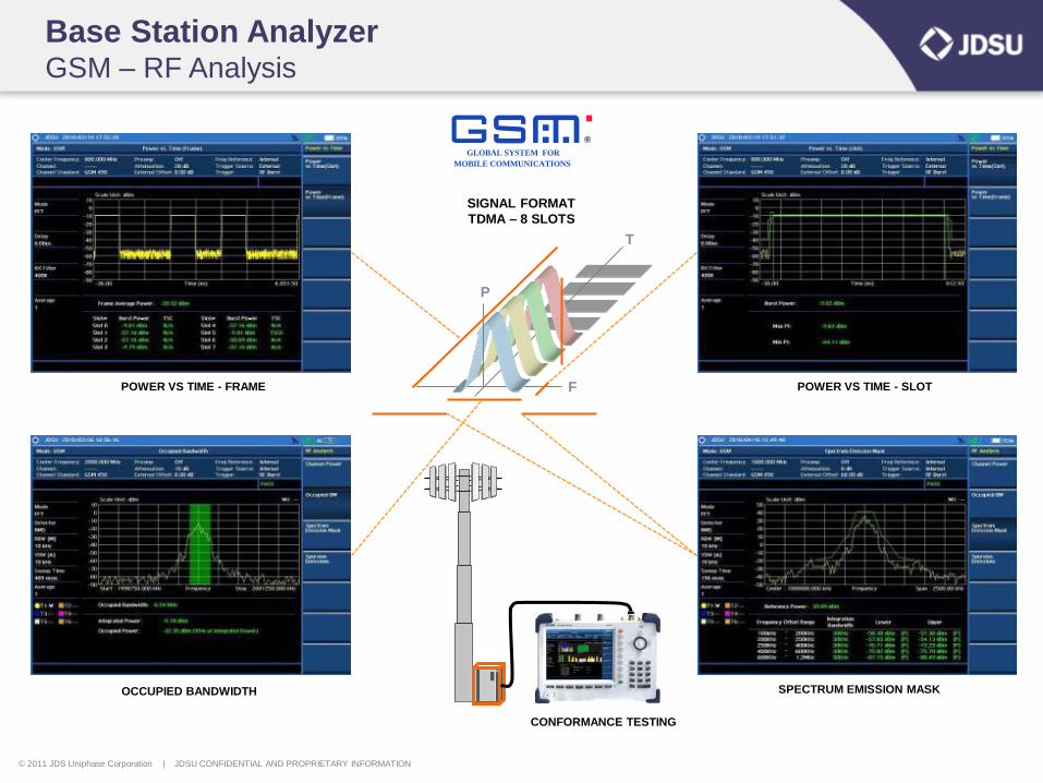
Base Station Analyzer GSM – RF Analysis
OCCUPIED BANDWIDTH
POWER VS TIME - SLOT
GLOBAL SYSTEM FOR
MOBILE COMMUNICATIONS
R
POWER VS TIME - FRAME
SIGNAL FORMAT
TDMA – 8 SLOTS
F
P
T
SPECTRUM EMISSION MASK
CONFORMANCE TESTING
© 2011 JDS Uniphase Corporation | JDSU CONFIDENTIAL AND PROPRIETARY INFORMATION
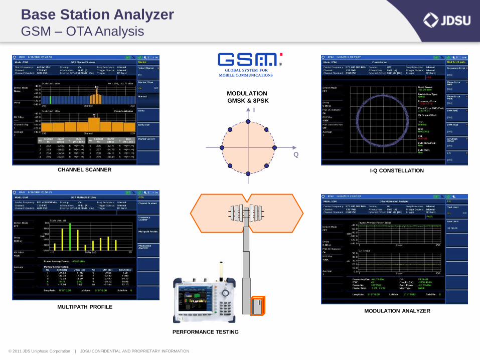
Base Station Analyzer GSM – OTA Analysis
CHANNEL SCANNER I-Q CONSTELLATION
GLOBAL SYSTEM FOR
MOBILE COMMUNICATIONS
R
I
Q
MODULATION
GMSK & 8PSK
MODULATION ANALYZER MULTIPATH PROFILE
PERFORMANCE TESTING
© 2011 JDS Uniphase Corporation | JDSU CONFIDENTIAL AND PROPRIETARY INFORMATION
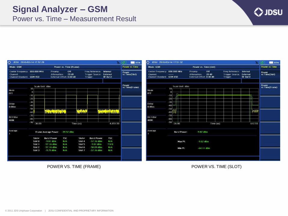
Signal Analyzer – GSM Power vs. Time – Measurement Result
POWER VS. TIME (FRAME) POWER VS. TIME (SLOT)
© 2011 JDS Uniphase Corporation | JDSU CONFIDENTIAL AND PROPRIETARY INFORMATION
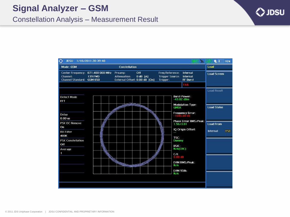
Signal Analyzer – GSM
Constellation Analysis – Measurement Result
© 2011 JDS Uniphase Corporation | JDSU CONFIDENTIAL AND PROPRIETARY INFORMATION
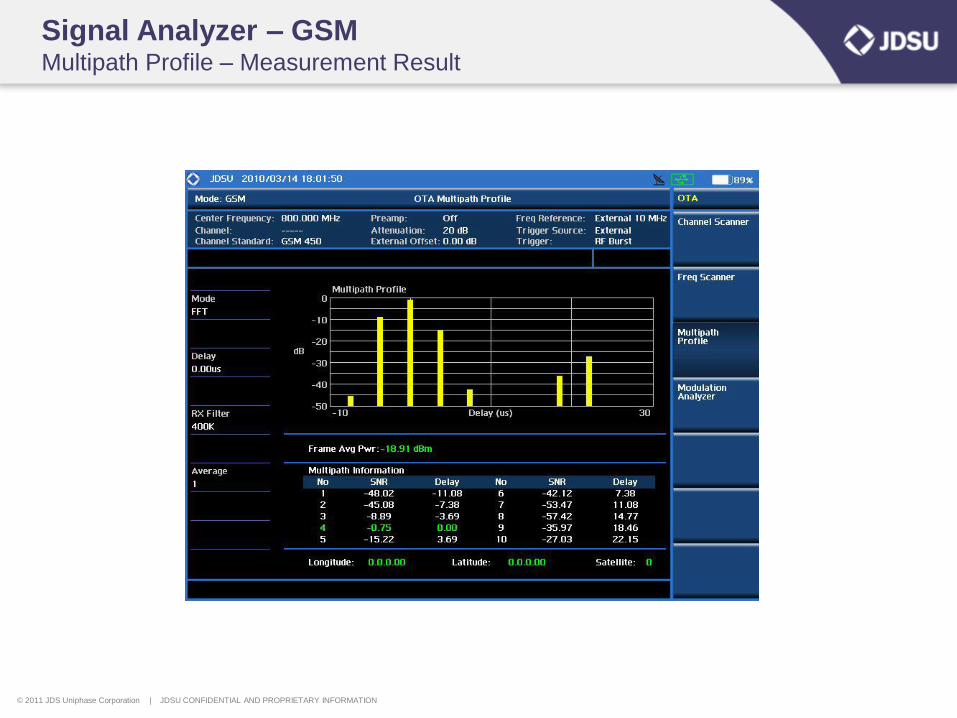
Signal Analyzer – GSM Multipath Profile – Measurement Result
© 2011 JDS Uniphase Corporation | JDSU CONFIDENTIAL AND PROPRIETARY INFORMATION
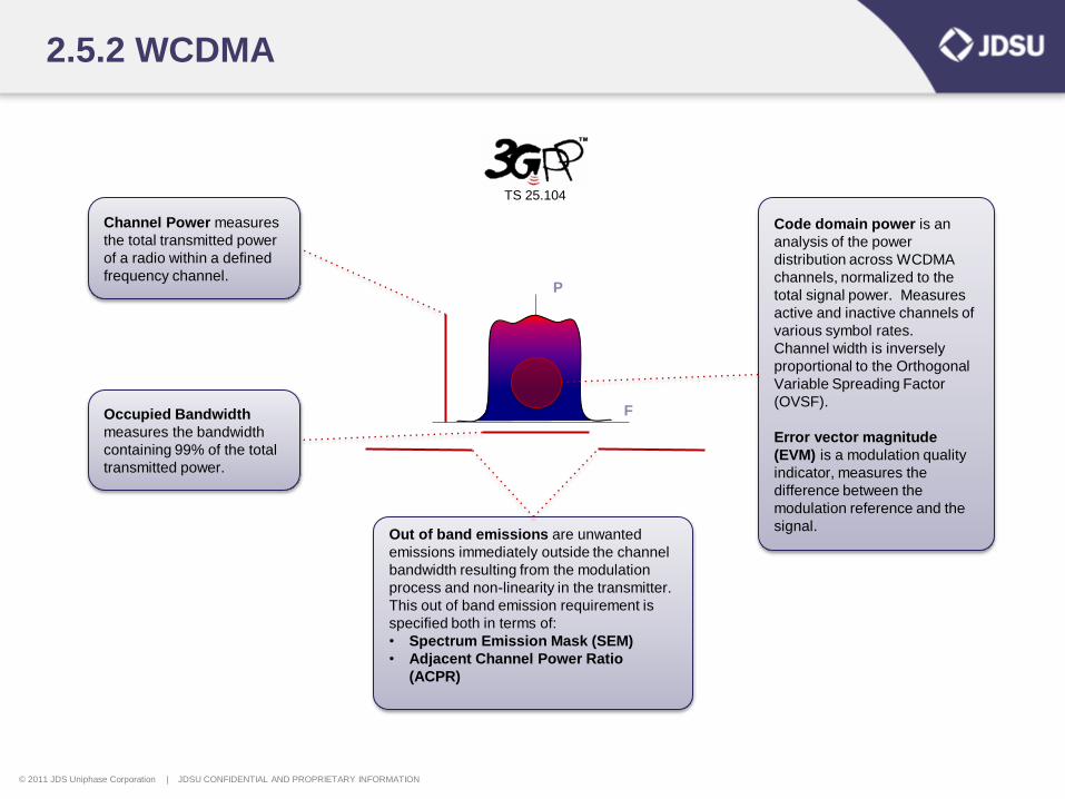
Out of band emissions are unwanted
emissions immediately outside the channel
bandwidth resulting from the modulation
process and non-linearity in the transmitter.
This out of band emission requirement is
specified both in terms of:
• Spectrum Emission Mask (SEM)
• Adjacent Channel Power Ratio
(ACPR)
Occupied Bandwidth
measures the bandwidth
containing 99% of the total
transmitted power.
Channel Power measures
the total transmitted power
of a radio within a defined
frequency channel.
2.5.2 WCDMA
F
P
TS 25.104
Code domain power is an
analysis of the power
distribution across WCDMA
channels, normalized to the
total signal power. Measures
active and inactive channels of
various symbol rates.
Channel width is inversely
proportional to the Orthogonal
Variable Spreading Factor
(OVSF).
Error vector magnitude
(EVM) is a modulation quality
indicator, measures the
difference between the
modulation reference and the
signal.
© 2011 JDS Uniphase Corporation | JDSU CONFIDENTIAL AND PROPRIETARY INFORMATION
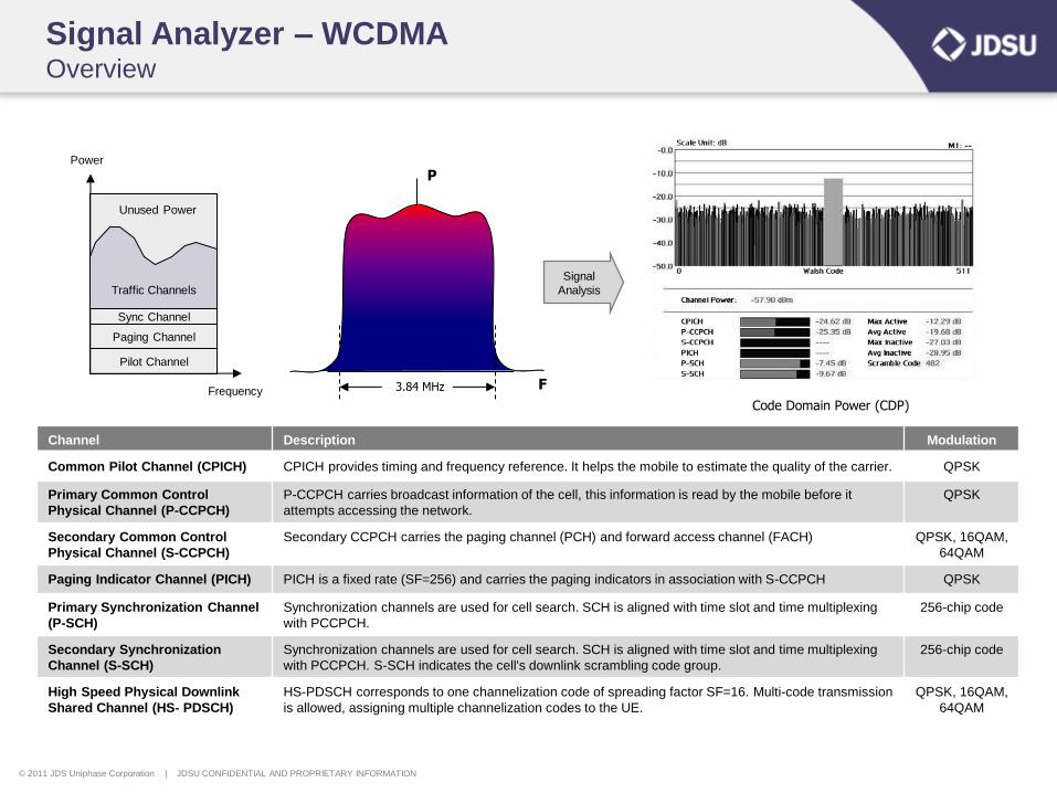
Signal Analyzer – WCDMA Overview
F
P
3.84 MHz
Code Domain Power (CDP)
Channel Description Modulation
Common Pilot Channel (CPICH) CPICH provides timing and frequency reference. It helps the mobile to estimate the quality of the carrier. QPSK
Primary Common Control
Physical Channel (P-CCPCH)
P-CCPCH carries broadcast information of the cell, this information is read by the mobile before it
attempts accessing the network.
QPSK
Secondary Common Control
Physical Channel (S-CCPCH)
Secondary CCPCH carries the paging channel (PCH) and forward access channel (FACH) QPSK, 16QAM,
64QAM
Paging Indicator Channel (PICH) PICH is a fixed rate (SF=256) and carries the paging indicators in association with S-CCPCH QPSK
Primary Synchronization Channel
(P-SCH)
Synchronization channels are used for cell search. SCH is aligned with time slot and time multiplexing
with PCCPCH.
256-chip code
Secondary Synchronization
Channel (S-SCH)
Synchronization channels are used for cell search. SCH is aligned with time slot and time multiplexing
with PCCPCH. S-SCH indicates the cell's downlink scrambling code group.
256-chip code
High Speed Physical Downlink
Shared Channel (HS- PDSCH)
HS-PDSCH corresponds to one channelization code of spreading factor SF=16. Multi-code transmission
is allowed, assigning multiple channelization codes to the UE.
QPSK, 16QAM,
64QAM
Signal
Analysis
Pilot Channel
Paging Channel
Sync Channel
Traffic Channels
Unused Power
Frequency
Power
© 2011 JDS Uniphase Corporation | JDSU CONFIDENTIAL AND PROPRIETARY INFORMATION
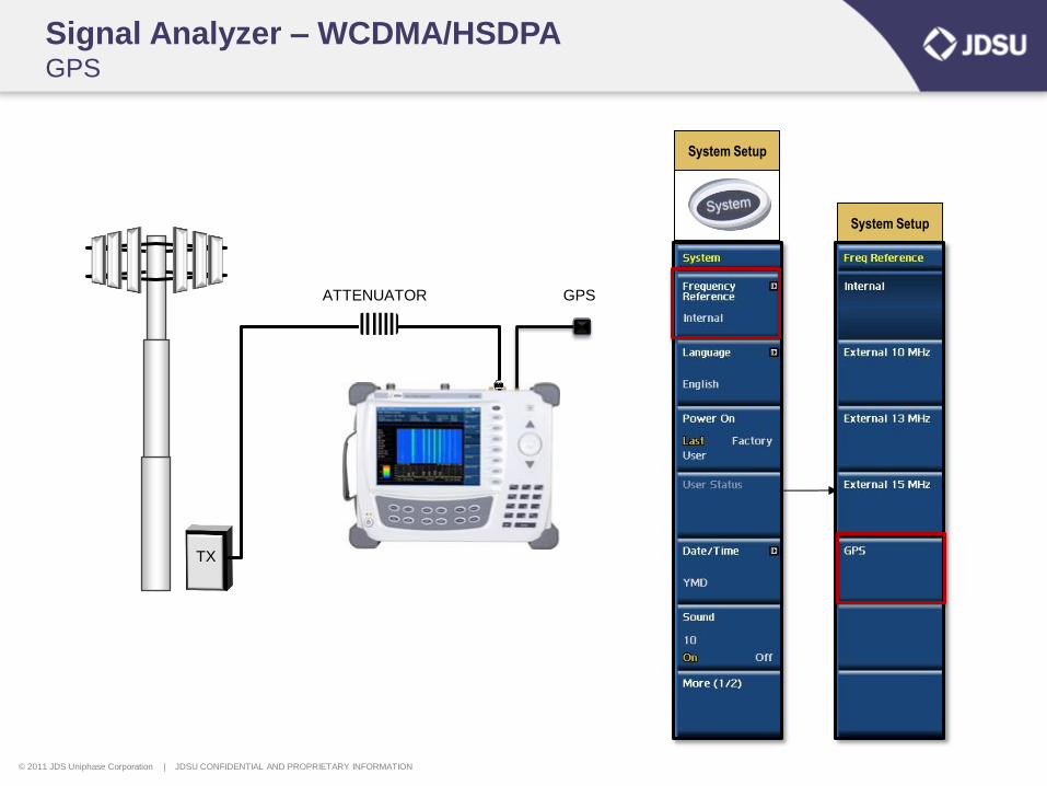
System Setup
Signal Analyzer – WCDMA/HSDPA GPS
ATTENUATOR
TX
GPS
System Setup
© 2011 JDS Uniphase Corporation | JDSU CONFIDENTIAL AND PROPRIETARY INFORMATION
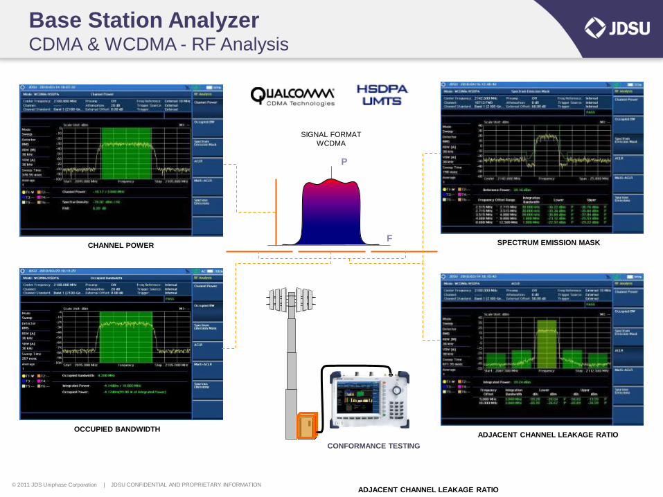
Base Station Analyzer CDMA & WCDMA - RF Analysis
CHANNEL POWER
OCCUPIED BANDWIDTH
SPECTRUM EMISSION MASK
ADJACENT CHANNEL LEAKAGE RATIO
SIGNAL FORMAT
WCDMA
F
P
CONFORMANCE TESTING
ADJACENT CHANNEL LEAKAGE RATIO
© 2011 JDS Uniphase Corporation | JDSU CONFIDENTIAL AND PROPRIETARY INFORMATION
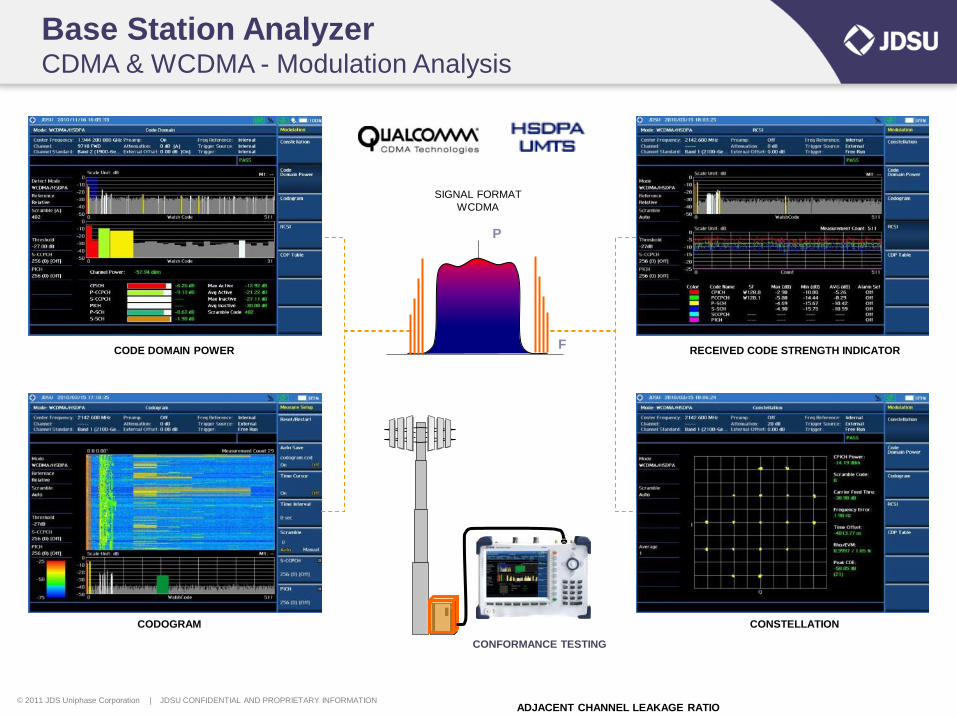
Base Station Analyzer CDMA & WCDMA - Modulation Analysis
CODE DOMAIN POWER
CODOGRAM
RECEIVED CODE STRENGTH INDICATOR
ADJACENT CHANNEL LEAKAGE RATIO
SIGNAL FORMAT
WCDMA
F
P
CONFORMANCE TESTING
CONSTELLATION
© 2011 JDS Uniphase Corporation | JDSU CONFIDENTIAL AND PROPRIETARY INFORMATION
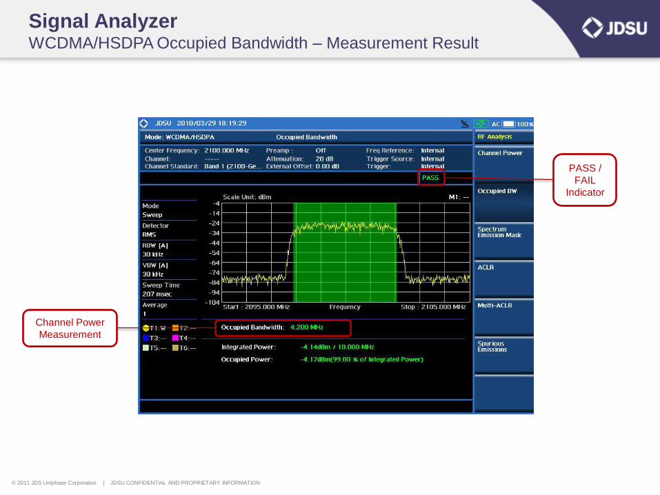
Signal Analyzer WCDMA/HSDPA Occupied Bandwidth – Measurement Result
Channel Power
Measurement
PASS /
FAIL
Indicator
© 2011 JDS Uniphase Corporation | JDSU CONFIDENTIAL AND PROPRIETARY INFORMATION
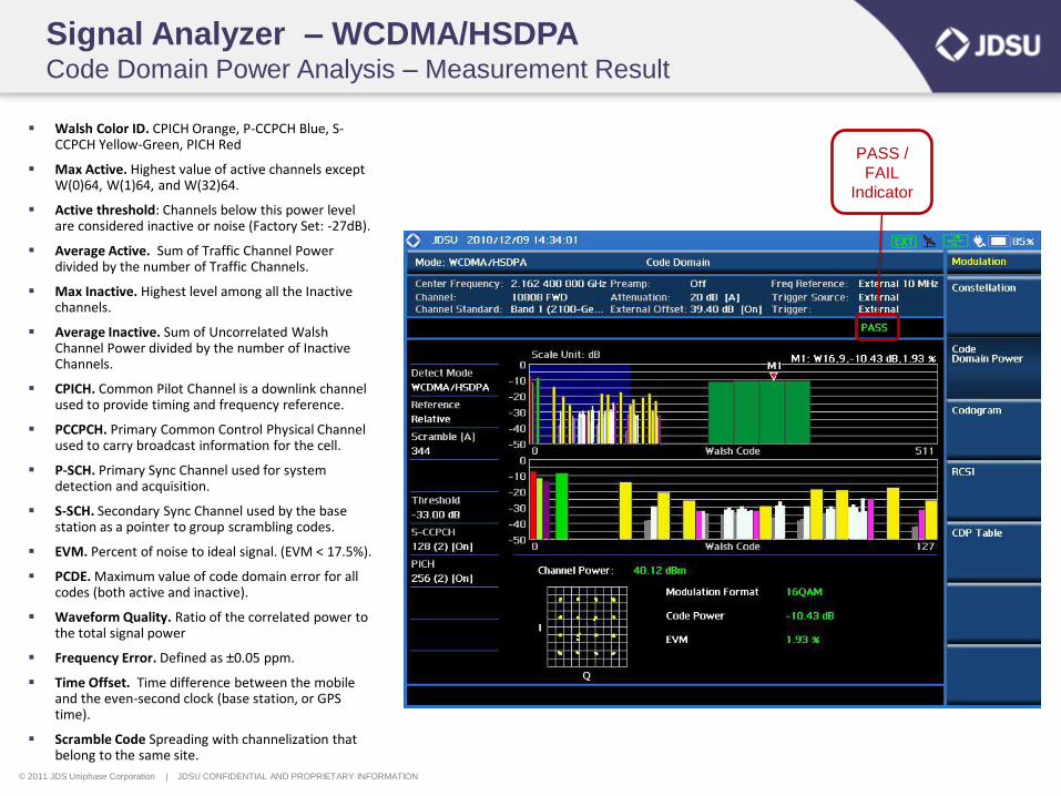
Signal Analyzer – WCDMA/HSDPA Code Domain Power Analysis – Measurement Result
PASS /
FAIL
Indicator
Walsh Color ID. CPICH Orange, P-CCPCH Blue, S-CCPCH Yellow-Green, PICH Red
Max Active. Highest value of active channels except W(0)64, W(1)64, and W(32)64.
Active threshold: Channels below this power level are considered inactive or noise (Factory Set: -27dB).
Average Active. Sum of Traffic Channel Power divided by the number of Traffic Channels.
Max Inactive. Highest level among all the Inactive channels.
Average Inactive. Sum of Uncorrelated Walsh Channel Power divided by the number of Inactive Channels.
CPICH. Common Pilot Channel is a downlink channel used to provide timing and frequency reference.
PCCPCH. Primary Common Control Physical Channel used to carry broadcast information for the cell.
P-SCH. Primary Sync Channel used for system detection and acquisition.
S-SCH. Secondary Sync Channel used by the base station as a pointer to group scrambling codes.
EVM. Percent of noise to ideal signal. (EVM < 17.5%).
PCDE. Maximum value of code domain error for all codes (both active and inactive).
Waveform Quality. Ratio of the correlated power to the total signal power
Frequency Error. Defined as ±0.05 ppm.
Time Offset. Time difference between the mobile and the even-second clock (base station, or GPS time).
Scramble Code Spreading with channelization that belong to the same site.
© 2011 JDS Uniphase Corporation | JDSU CONFIDENTIAL AND PROPRIETARY INFORMATION
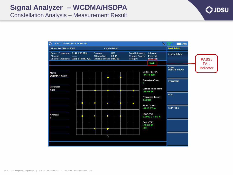
Signal Analyzer – WCDMA/HSDPA Constellation Analysis – Measurement Result
PASS /
FAIL
Indicator
© 2011 JDS Uniphase Corporation | JDSU CONFIDENTIAL AND PROPRIETARY INFORMATION
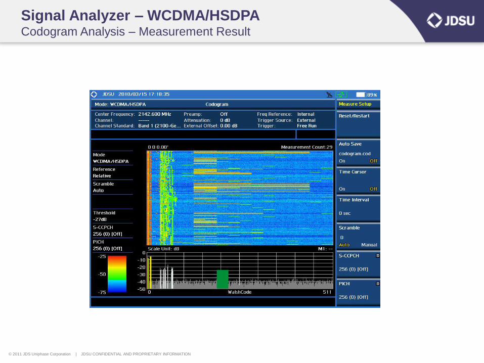
Signal Analyzer – WCDMA/HSDPA Codogram Analysis – Measurement Result
© 2011 JDS Uniphase Corporation | JDSU CONFIDENTIAL AND PROPRIETARY INFORMATION
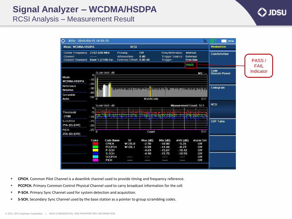
Signal Analyzer – WCDMA/HSDPA RCSI Analysis – Measurement Result
PASS /
FAIL
Indicator
CPICH. Common Pilot Channel is a downlink channel used to provide timing and frequency reference.
PCCPCH. Primary Common Control Physical Channel used to carry broadcast information for the cell.
P-SCH. Primary Sync Channel used for system detection and acquisition.
S-SCH. Secondary Sync Channel used by the base station as a pointer to group scrambling codes.
© 2011 JDS Uniphase Corporation | JDSU CONFIDENTIAL AND PROPRIETARY INFORMATION
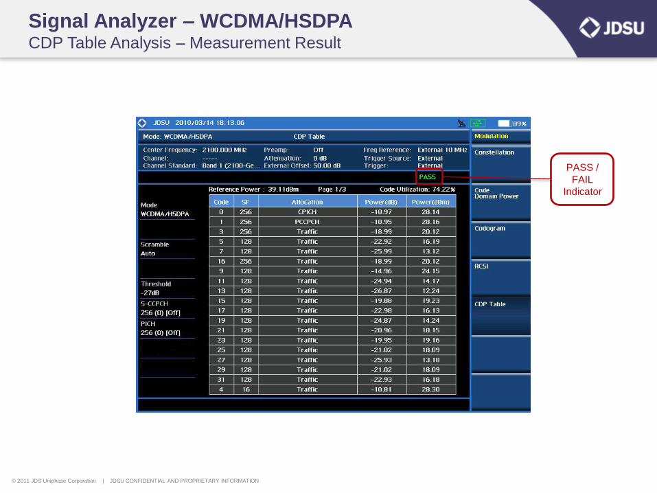
Signal Analyzer – WCDMA/HSDPA CDP Table Analysis – Measurement Result
PASS /
FAIL
Indicator
© 2011 JDS Uniphase Corporation | JDSU CONFIDENTIAL AND PROPRIETARY INFORMATION
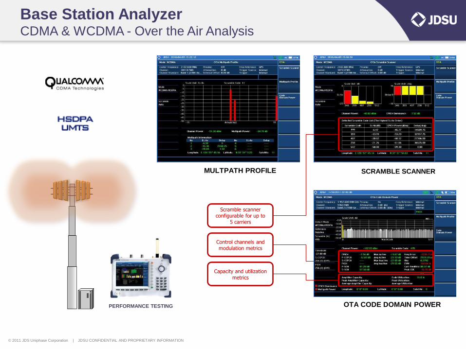
Base Station Analyzer CDMA & WCDMA - Over the Air Analysis
MULTPATH PROFILE SCRAMBLE SCANNER
OTA CODE DOMAIN POWER
Scramble scanner configurable for up to
5 carriers
Control channels and modulation metrics
Capacity and utilization metrics
PERFORMANCE TESTING
© 2011 JDS Uniphase Corporation | JDSU CONFIDENTIAL AND PROPRIETARY INFORMATION
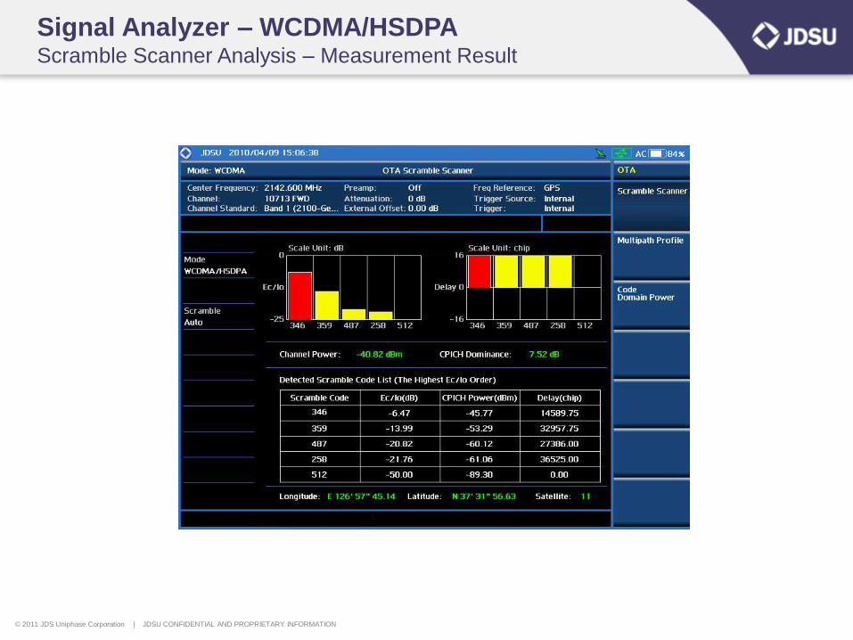
Signal Analyzer – WCDMA/HSDPA Scramble Scanner Analysis – Measurement Result

© 2011 JDS Uniphase Corporation | JDSU CONFIDENTIAL AND PROPRIETARY INFORMATION
Signal Analyzer – WCDMA/HSDPA Multipath Profile Analysis – Measurement Result
© 2011 JDS Uniphase Corporation | JDSU CONFIDENTIAL AND PROPRIETARY INFORMATION
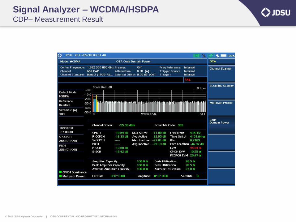
Signal Analyzer – WCDMA/HSDPA CDP– Measurement Result
© 2011 JDS Uniphase Corporation | JDSU CONFIDENTIAL AND PROPRIETARY INFORMATION
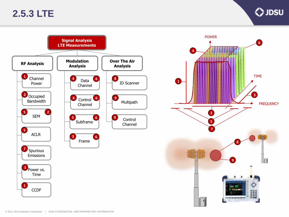
2.5.3 LTE
Signal Analysis LTE Measurements
RF Analysis Modulation
Analysis
Channel Power
Occupied Bandwidth
ACLR
SEM
Spurious Emissions
Data Channel
Control Channel
Frame
Subframe
Power vs. Time
CCDF
1
2
3
4
5
6
POWER
FREQUENCY
TIME 1
2
3
4
5
5
7
6 4
6
3 6
3 6
1
2
7
9
8
Over The Air Analysis
ID Scanner
Multipath
Control Channel
8
9
9
© 2011 JDS Uniphase Corporation | JDSU CONFIDENTIAL AND PROPRIETARY INFORMATION
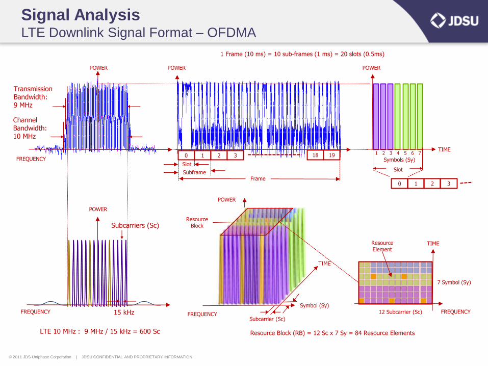
Channel Bandwidth: 10 MHz
Transmission Bandwidth: 9 MHz
POWER
FREQUENCY 15 kHz
Subcarriers (Sc)
POWER
TIME
Symbols (Sy)
1 2 3 4 5 6 7
Slot
LTE 10 MHz : 9 MHz / 15 kHz = 600 Sc
1 Frame (10 ms) = 10 sub-frames (1 ms) = 20 slots (0.5ms)
Signal Analysis LTE Downlink Signal Format – OFDMA
FREQUENCY
POWER POWER
Resource Block (RB) = 12 Sc x 7 Sy = 84 Resource Elements
POWER
FREQUENCY
TIME
Symbol (Sy)
Subcarrier (Sc)
Resource Block
TIME
FREQUENCY
7 Symbol (Sy)
12 Subcarrier (Sc)
Resource Element
0 1 2 3 18 19
Slot
Subframe Frame
0 1 2 3
© 2011 JDS Uniphase Corporation | JDSU CONFIDENTIAL AND PROPRIETARY INFORMATION
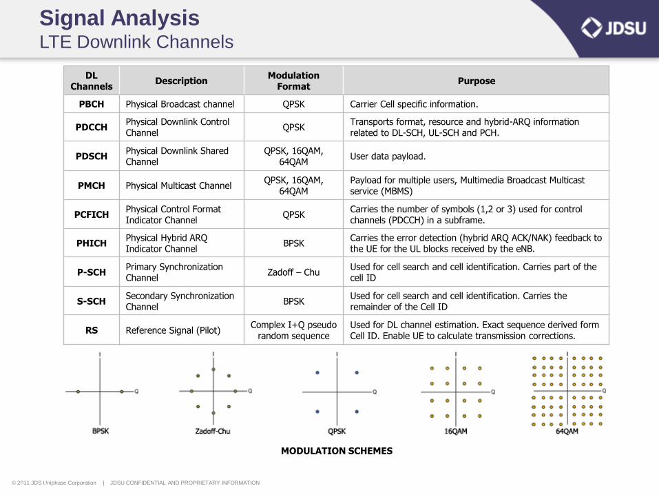
Signal Analysis LTE Downlink Channels
DL Channels
Description Modulation
Format Purpose
PBCH Physical Broadcast channel QPSK Carrier Cell specific information.
PDCCH Physical Downlink Control Channel
QPSK Transports format, resource and hybrid-ARQ information related to DL-SCH, UL-SCH and PCH.
PDSCH Physical Downlink Shared Channel
QPSK, 16QAM, 64QAM
User data payload.
PMCH Physical Multicast Channel QPSK, 16QAM,
64QAM Payload for multiple users, Multimedia Broadcast Multicast service (MBMS)
PCFICH Physical Control Format Indicator Channel
QPSK Carries the number of symbols (1,2 or 3) used for control channels (PDCCH) in a subframe.
PHICH Physical Hybrid ARQ Indicator Channel
BPSK Carries the error detection (hybrid ARQ ACK/NAK) feedback to the UE for the UL blocks received by the eNB.
P-SCH Primary Synchronization Channel
Zadoff – Chu Used for cell search and cell identification. Carries part of the cell ID
S-SCH Secondary Synchronization Channel
BPSK Used for cell search and cell identification. Carries the remainder of the Cell ID
RS Reference Signal (Pilot) Complex I+Q pseudo
random sequence Used for DL channel estimation. Exact sequence derived form Cell ID. Enable UE to calculate transmission corrections.
Page 48
MODULATION SCHEMES
© 2011 JDS Uniphase Corporation | JDSU CONFIDENTIAL AND PROPRIETARY INFORMATION
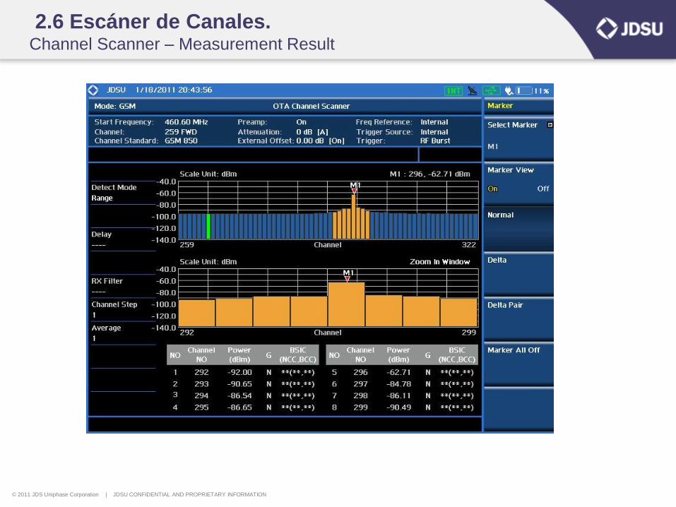
2.6 Escáner de Canales. Channel Scanner – Measurement Result

© 2011 JDS Uniphase Corporation | JDSU CONFIDENTIAL AND PROPRIETARY INFORMATION
Frequency Scanner – Measurement Result
© 2011 JDS Uniphase Corporation | JDSU CONFIDENTIAL AND PROPRIETARY INFORMATION
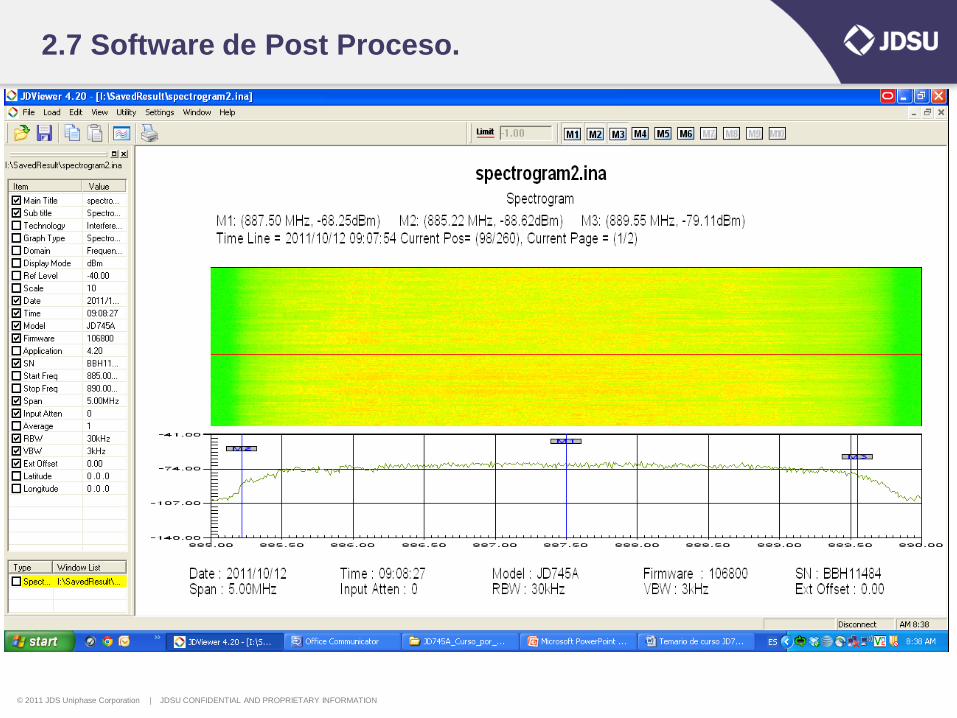
2.7 Software de Post Proceso.
© 2011 JDS Uniphase Corporation | JDSU CONFIDENTIAL AND PROPRIETARY INFORMATION
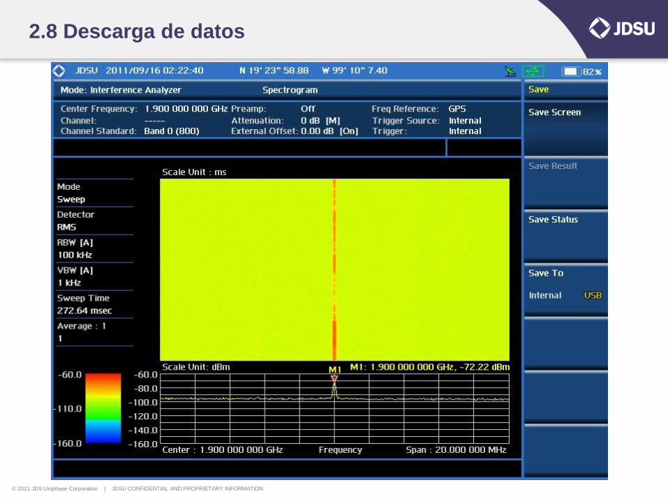
2.8 Descarga de datos
© 2011 JDS Uniphase Corporation | JDSU CONFIDENTIAL AND PROPRIETARY INFORMATION
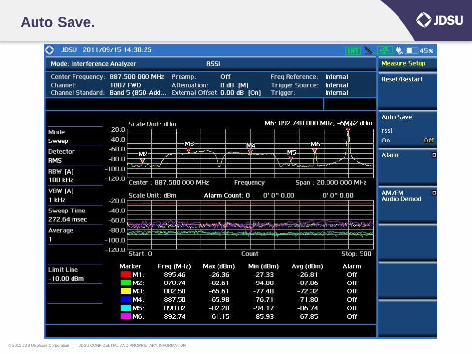
Auto Save.
© 2011 JDS Uniphase Corporation | JDSU CONFIDENTIAL AND PROPRIETARY INFORMATION
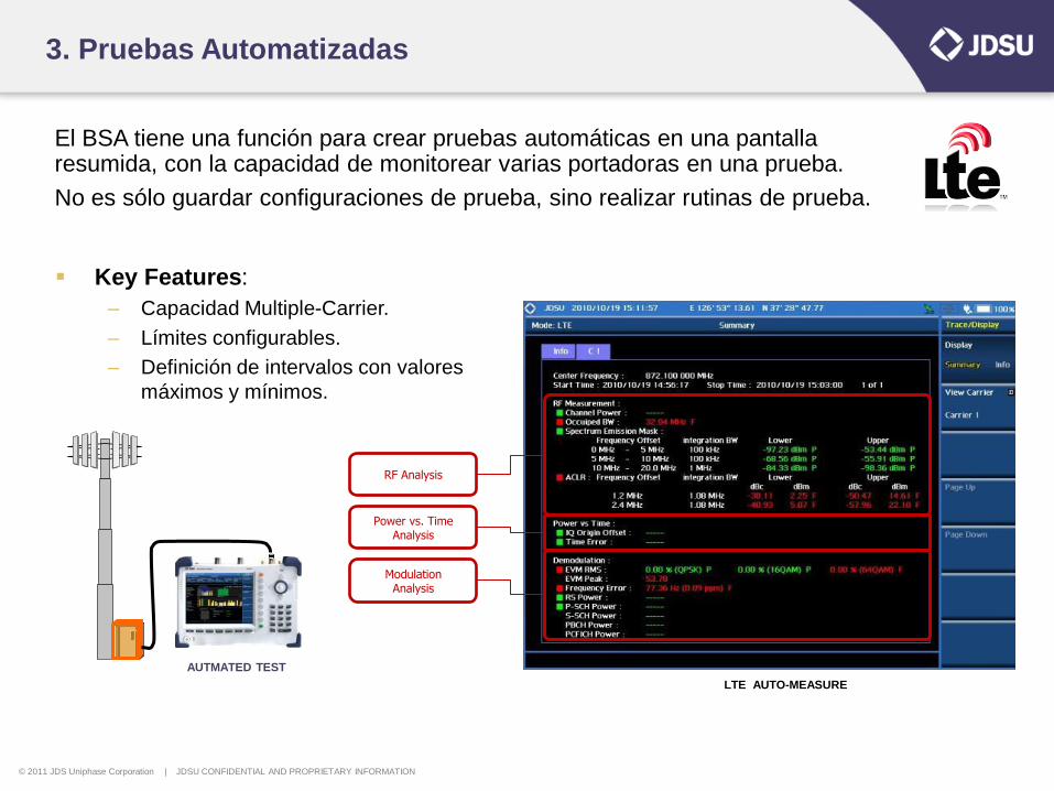
3. Pruebas Automatizadas
El BSA tiene una función para crear pruebas automáticas en una pantalla resumida, con la capacidad de monitorear varias portadoras en una prueba.
No es sólo guardar configuraciones de prueba, sino realizar rutinas de prueba.
Key Features:
– Capacidad Multiple-Carrier.
– Límites configurables.
– Definición de intervalos con valores
máximos y mínimos.
LTE AUTO-MEASURE
RF Analysis
Power vs. Time Analysis
Modulation Analysis
AUTMATED TEST
© 2011 JDS Uniphase Corporation | JDSU CONFIDENTIAL AND PROPRIETARY INFORMATION
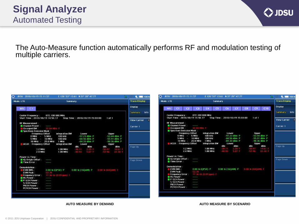
Signal Analyzer Automated Testing
The Auto-Measure function automatically performs RF and modulation testing of multiple carriers.
AUTO MEASURE BY DEMAND AUTO MEASURE BY SCENARIO
© 2011 JDS Uniphase Corporation | JDSU CONFIDENTIAL AND PROPRIETARY INFORMATION
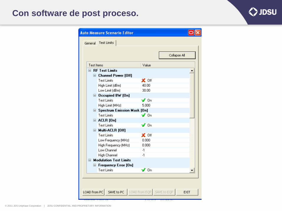
Con software de post proceso.