Embed Size (px)
Citation preview
1 Steel Design Guide
Base Plate and Anchor Rod Design
Second Edition
1Base Plate and
Anchor Rod Design
JAMES M. FISHER, Ph.D., P.E.Computerized Structural Design, S.C.
Milwaukee, Wisconsin
and
LAWRENCE A. KLOIBER, P.E.LeJuene Steel CompanyMinneapolis, Minnesota
AMERICAN INSTITUTE OF STEEL CONSTRUCTION, INC.
Second Edition
Steel Design Guide
Copyright © 2006
by
American Institute of Steel Construction, Inc.
All rights reserved. This book or any part thereofmust not be reproduced in any form without the
written permission of the publisher.
The information presented in this publication has been prepared in accordance with recognized engineering principles and is for general information only. While it is believed to be accurate, this information should not be used or relied upon for any specific application without compe-tent professional examination and verification of its accuracy, suitability, and applicability by a licensed professional engineer, designer, or architect. The publication of the material contained herein is not intended as a representation or warranty on the part of the American Institute of Steel Construction or of any other person named herein, that this information is suitable for any general or particular use or of freedom from infringement of any patent or patents. Anyone making use of this information assumes all liability arising from such use.
Caution must be exercised when relying upon other specifications and codes developed by other bodies and incorporated by reference herein since such material may be modified or amended from time to time subsequent to the printing of this edition. The Institute bears no responsi-bility for such material other than to refer to it and incorporate it by reference at the time of the initial publication of this edition.
Printed in the United States of America
First Printing: May 2006

AISC would also like to thank the following individuals who assisted in reviewing the drafts of this Design Guide for their insightful comments and suggestions.
v
Acknowledgements
The authors would like to thank Robert J. Dexter from the University of Minnesota, and Daeyong Lee from the Steel Structure Research Laboratory, Research Institute of Industrial Science & Technology (RIST), Kyeonggi-Do, South Korea, for their writing of Appendix A and the first draft of this Guide. The authors also recognize the contribu-tions of the authors of the first edition of this guide, John DeWolf from the University of Connecticut and David Ricker (retired) from Berlin Steel Construction Company, and thank Christopher Hewitt and Kurt Gustafson of AISC for their careful reading, suggestions, and their writing of Appendix B. Special appreciation is also extended to Carol T. Williams of Computerized Structural Design for typing the manuscript.
Victoria ArbitrioReidar BjorhovdeCrystal BlantonCharles J. CarterBrad DavisRobert O. DisqueJames DoyleRichard M. DrakeSamuel S. EskildsenDaniel M. FalconerMarshall T. FerrellRoger D. HamiltonJohn HarrisAllen J. Harrold
Donald JohnsonGeoffrey L. KulakBill R. Lindley IIDavid McKenzieRichard OrrDavis G. Parsons IIWilliam T. SeguiDavid F. SharpVictor ShneurBozidar StojadinovicRaymond TideGary C. VioletteFloyd J. Vissat

vi
vii
Table of Contents1.0 INTRODUCTION .....................................................1
2.0 MATERIAL, FABRICATION, INSTALLATION, AND REPAIRS ..........................2
2.1 Material Specifications ...................................... 2
2.2 Base Plate Material Selection ............................ 2
2.3 Base Plate Fabrication and Finishing ................ 3
2.4 Base Plate Welding ............................................ 4
2.5 Anchor Rod Material ......................................... 5
2.6 Anchor Rod Holes and Washers ........................ 6
2.7 Anchor Rod Sizing and Layout ......................... 7
2.8 Anchor Rod Placement and Tolerances ............ 7
2.9 Column Erection Procedures ............................. 8
2.9.1 Setting Nut and Washer Method ............. 8
2.9.2 Setting Plate Method .............................. 9
2.9.3 Shim Stack Method ................................ 9
2.9.4 Setting Large Base Plates ....................... 9
2.10 Grouting Requirements ..................................... 9
2.11 Anchor Rod Repairs ........................................ 10
2.11.1 Anchor Rods in the Wrong Position .... 10
2.11.2 Anchor Rods Bent or Not Vertical ....... 10
2.11.3 Anchor Rod Projection Too Long or Too Short .......................................... 10
2.11.4 Anchor Rod Pattern Rotated 90° .......... 12
2.12 Details for Seismic Design D .......................... 12
3.0 DESIGN OF COLUMN BASE PLATE CONNECTIONS .......................................13
3.1 Concentric Compressive Axial Loads ............. 14
3.1.1 Concrete Bearing Limit ........................ 14
3.1.2 Base Plate Yielding Limit (W-Shapes) ........................................... 15
3.1.3 Base Plate Yielding Limit (HSS and Pipe) ................................... 16
3.1.4 General Design Procedure .................... 16
3.2 Tensile Axial Loads ......................................... 18
3.2.1 Anchore Rod Tension ........................... 19
3.2.2 Concrete Anchorage for Tensile Forces ....................................... 19
3.3 Design of Column Base Plates with Small Moments ................................................ 23
3.3.1 Concrete Bearing Stress ....................... 24
3.3.2 Base Plate Flexural Yielding Limit at Bearing Interface .................... 24
3.3.3 Base Plate Flexural Yielding at Tension Interface ............................... 25
3.3.4 General Design Procedure .................... 25
3.4 Design of Column Base Plates with Large Moments ................................................ 25
3.4.1 Concrete Bearing and Anchor Rod Forces ............................... 25
3.4.2 Base Plate Yielding Limit at Bearing Interface .............................. 26
3.4.3 Base Plate Yielding Limit at Tension Interface ............................... 27
3.4.4 General Design Procedure .................... 27
3.5 Design for Shear .............................................. 27
3.5.1 Friction .................................................. 27
3.5.2 Bearing .................................................. 27
3.5.3 Shear in Anchor Rods ........................... 29
3.5.4 Interaction of Tension and Shear in the Concrete ........................... 30
3.5.5 Hairpins and Tie Rods .......................... 30
4.0 DESIGN EXAMPLES ............................................31
4.1 Example: Base Plate for Concentric Axial Compressive Load (No concrete confinement) .............................. 31
4.2 Example: Base Plate for Concentrix Axial Compressive Load (Using concrete confinement) ......................... 32
4.3 Example: Available Tensile Strength of a w-in. Anchor Rod ............................................ 34
4.4 Example: Concerete Embedment Strength ..... 34
4.5 Example: Column Anchorage for Tensile Loads ................................................... 34
4.6 Example: Small Moment Base Plate Design .. 37
4.7 Example: Large Moment Base Plate Design .. 38
4.8 Example: Shear Transfer Using Bearing ......... 40
4.9 Example: Shear Lug Design ............................ 40
4.10 Example: Edge Disttance for Shear ................ 42
4.11 Example: Anchor Rod Resisting Combined Tension and Shear ........................................... 42
REFERENCES ...............................................................45
APPENDIX A .................................................................47
APPENDIX B .................................................................55

viii
1.0 INTRODUCTION
Column base plate connections are the critical interface between the steel structure and the foundation. These con-nections are used in buildings to support gravity loads and function as part of lateral-load-resisting systems. In addition, they are used for mounting of equipment and in outdoor sup-port structures, where they may be affected by vibration and fatigue due to wind loads.
Base plates and anchor rods are often the last structural steel items to be designed but are the first items required on the jobsite. The schedule demands along with the prob-lems that can occur at the interface of structural steel and reinforced concrete make it essential that the design details take into account not only structural requirements, but also include consideration of constructability issues, especially anchor rod setting procedures and tolerances. The impor-tance of the accurate placement of anchor rods cannot be over-emphasized. This is the one of the key components to safely erecting and accurately plumbing the building.
The material in this Guide is intended to provide guidelines for engineers and fabricators to design, detail, and specify column-base-plate and anchor rod connections in a manner that avoids common fabrication and erection problems. This Guide is based on the 2005 AISC Specification for Structur-al Steel Buildings (AISC, 2005), and includes guidance for designs made in accordance with load and resistance factor design (LRFD) or allowable stress design (ASD).
This Guide follows the format of the 2005 AISC Specifi-cation, developing strength parameters for foundation sys-tem design in generic terms that facilitate either load and resistance factor design (LRFD) or allowable strength de-sign (ASD). Column bases and portions of the anchorage design generally can be designed in a direct approach based on either LRFD or ASD load combinations. The one area of anchorage design that is not easily designed by ASD is the embedment of anchor rods into concrete. This is due to the common use of ACI 318 Appendix D, which is exclu-sively based on the strength approach (LRFD) for the design of such embedment. Other steel elements of the foundation system, including the column base plate and the sizing of anchor diameters are equally proficient to evaluation using LRFD or ASD load methods. In cases such as anchors sub-jected to neither tension nor shear, the anchorage develop-ment requirement may be a relatively insignificant factor.
The generic approach in development of foundation de-sign parameters taken in this Guide permits the user a choice to develop the loads based on either the LRFD or ASD ap-proach. The derivations of foundation design parameters, as presented herein, are then either multiplied by the resistance factor, φ, or divided by a safety factor, Ω, based on the ap-propriate load system utilized in the analysis; consistent with the approach used in the 2005 Specification. Many of
the equations shown herein are independent of the load ap-proach and thus are applicable to either design methodology. These are shown in singular format. Other derived equations are based on the particular load approach and are presented in a side-by-side format of comparable equations for LRFD or ASD application.
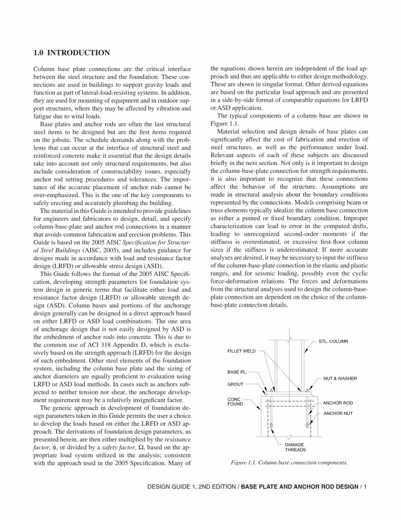
The typical components of a column base are shown in Figure 1.1.
Material selection and design details of base plates can significantly affect the cost of fabrication and erection of steel structures, as well as the performance under load. Relevant aspects of each of these subjects are discussed briefly in the next section. Not only is it important to design the column-base-plate connection for strength requirements, it is also important to recognize that these connections affect the behavior of the structure. Assumptions are made in structural analysis about the boundary conditions represented by the connections. Models comprising beam or truss elements typically idealize the column base connection as either a pinned or fixed boundary condition. Improper characterization can lead to error in the computed drifts, leading to unrecognized second-order moments if the stiffness is overestimated, or excessive first-floor column sizes if the stiffness is underestimated. If more accurate analyses are desired, it may be necessary to input the stiffness of the column-base-plate connection in the elastic and plastic ranges, and for seismic loading, possibly even the cyclic force-deformation relations. The forces and deformations from the structural analyses used to design the column-base-plate connection are dependent on the choice of the column-base-plate connection details.
Figure 1.1. Column base connection components.
DESIGN GUIDE 1, 2ND EDITION / BASE PLATE AND ANCHOR ROD DESIGN / 1
2 / DESIGN GUIDE 1, 2ND EDITION / BASE PLATE AND ANCHOR ROD DESIGN
The vast majority of building columns are designed for axial compression only with little or no uplift. For such col-umns, the simple column-base-plate connection detail shown in Figure 1.1 is sufficient. The design of column-base-plate connections for axial compression only is presented in Sec-tion 3. The design is simple and need not be encumbered with many of the more complex issues discussed in Appen-dix A, which pertains to special structures. Anchor rods for gravity columns are often not required for the permanent structure and need only be sized to provide for column sta-bility during erection.
Column base plate connections are also capable of trans-mitting uplift forces and can transmit shear through the an-chor rods if required. If the base plate remains in compres-sion, shear can be transmitted through friction against the grout pad or concrete; thus, the anchor rods are not required to be designed for shear. Large shear forces can be resisted by bearing against concrete, either by embedding the col-umn base or by adding a shear lug under the base plate.
Column base plate moment connections can be used to resist wind and seismic loads on the building frame. Moment at the column base can be resisted by development of a force couple between bearing on the concrete and tension in some or all of the anchor rods.
This guide will enable the designer to design and specify economical column base plate details that perform adequate-ly for the specified demand. The objective of the design pro-cess in this Guide is that under service loading and under ex-treme loading in excess of the design loads, the behavior of column base plates should be close to that predicted by the approximate mathematical equations in this Design Guide.
Historically, two anchor rods have been used in the area bounded by column flanges and web. Recent regulations of the U.S. Occupational Safety and Health Administration (OSHA) Safety Standards for Steel Erection (OSHA, 2001) (Subpart R of 29 CFR Part 1926) require four anchor rods in almost all column-base-plate connections and require all col-umns to be designed for a specific bending moment to reflect
the stability required during erection with an ironworker on the column. This regulation has essentially eliminated the typical detail with two anchor rods except for small post-type structures that weigh less than 300 lb (e.g., doorway portal frames).
This Guide supersedes the original AISC Design Guide 1, Column Base Plates. In addition to the OSHA regulations, there has been significant research and improved design guidelines issued subsequent to the publication of Design Guide 1 in 1990. The ACI Building Code Requirements for Structural Concrete (ACI, 2002) has improved provisions for the pullout and breakout strength of anchor rods and other embedded anchors. Design guidance for anchor rods based on the ACI recommendations is included, along with practical suggestions for detailing and installing anchor rod assemblies. These guidelines deal principally with cast-in-place anchors and with their design, installation, inspection, and repair in column-base-plate connections.
The AISC Design Guide 7, 2nd edition, Industrial Build-ings: Roofs to Column Anchorage (Fisher, 2004), contains additional examples and discussion relative to the design of anchor rods.
2.0 MATERIALS, FABRICATION, INSTALLATION, AND REPAIRS
2.1 Material Specifications
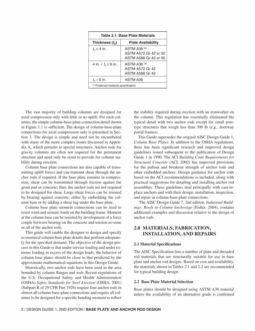
The AISC Specification lists a number of plate and threaded rod materials that are structurally suitable for use in base plate and anchor rod designs. Based on cost and availability, the materials shown in Tables 2.1 and 2.2 are recommended for typical building design.
2.2 Base Plate Material Selection
Base plates should be designed using ASTM A36 material unless the availability of an alternative grade is confirmed
Table 2.1. Base Plate Materials
Thickness (tp) Plate Availability
tp ≤ 4 in. ASTM A36 [a]
ASTM A572 Gr 42 or 50ASTM A588 Gr 42 or 50
4 in. < tp ≤ 6 in. ASTM A36 [a]
ASTM A572 Gr 42ASTM A588 Gr 42
tp > 6 in. ASTM A36[a] Preferred material specification
DESIGN GUIDE 1, 2ND EDITION / BASE PLATE AND ANCHOR ROD DESIGN / 3
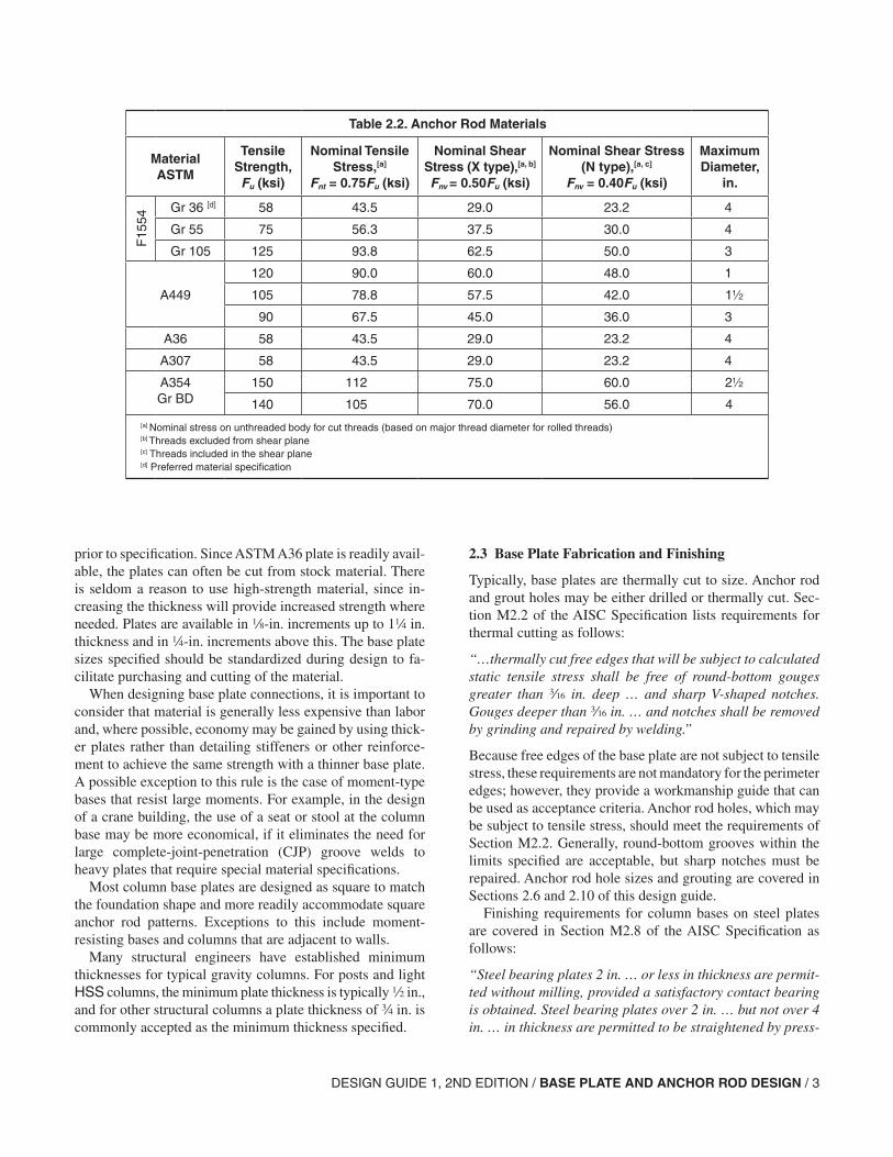
Table 2.2. Anchor Rod Materials
MaterialASTM
Tensile Strength,Fu (ksi)
Nominal Tensile Stress,[a]
Fnt = 0.75Fu (ksi)
Nominal Shear Stress (X type),[a, b]
Fnv = 0.50Fu (ksi)
Nominal Shear Stress (N type),[a, c]
Fnv = 0.40Fu (ksi)
Maximum Diameter,
in.
F15
54
Gr 36 [d] 58 43.5 29.0 23.2 4
Gr 55 75 56.3 37.5 30.0 4
Gr 105 125 93.8 62.5 50.0 3
A449
120 90.0 60.0 48.0 1
105 78.8 57.5 42.0 1
90 67.5 45.0 36.0 3
A36 58 43.5 29.0 23.2 4
A307 58 43.5 29.0 23.2 4
A354Gr BD
150 112 75.0 60.0 2
140 105 70.0 56.0 4[a] Nominal stress on unthreaded body for cut threads (based on major thread diameter for rolled threads)[b] Threads excluded from shear plane[c] Threads included in the shear plane[d] Preferred material specification
prior to specification. Since ASTM A36 plate is readily avail-able, the plates can often be cut from stock material. There is seldom a reason to use high-strength material, since in-creasing the thickness will provide increased strength where needed. Plates are available in 8-in. increments up to 14 in. thickness and in 4-in. increments above this. The base plate sizes specified should be standardized during design to fa-cilitate purchasing and cutting of the material.
When designing base plate connections, it is important to consider that material is generally less expensive than labor and, where possible, economy may be gained by using thick-er plates rather than detailing stiffeners or other reinforce-ment to achieve the same strength with a thinner base plate. A possible exception to this rule is the case of moment-type bases that resist large moments. For example, in the design of a crane building, the use of a seat or stool at the column base may be more economical, if it eliminates the need for large complete-joint-penetration (CJP) groove welds to heavy plates that require special material specifications.
Most column base plates are designed as square to match the foundation shape and more readily accommodate square anchor rod patterns. Exceptions to this include moment-resisting bases and columns that are adjacent to walls.
Many structural engineers have established minimum thicknesses for typical gravity columns. For posts and light HSS columns, the minimum plate thickness is typically 2 in., and for other structural columns a plate thickness of w in. is commonly accepted as the minimum thickness specified.
2.3 Base Plate Fabrication and Finishing
Typically, base plates are thermally cut to size. Anchor rod and grout holes may be either drilled or thermally cut. Sec-tion M2.2 of the AISC Specification lists requirements for thermal cutting as follows:
“…thermally cut free edges that will be subject to calculated static tensile stress shall be free of round-bottom gouges greater than x in. deep … and sharp V-shaped notches. Gouges deeper than x in. … and notches shall be removed by grinding and repaired by welding.”
Because free edges of the base plate are not subject to tensile stress, these requirements are not mandatory for the perimeter edges; however, they provide a workmanship guide that can be used as acceptance criteria. Anchor rod holes, which may be subject to tensile stress, should meet the requirements of Section M2.2. Generally, round-bottom grooves within the limits specified are acceptable, but sharp notches must be repaired. Anchor rod hole sizes and grouting are covered in Sections 2.6 and 2.10 of this design guide.
Finishing requirements for column bases on steel plates are covered in Section M2.8 of the AISC Specification as follows:
“Steel bearing plates 2 in. … or less in thickness are permit-ted without milling, provided a satisfactory contact bearing is obtained. Steel bearing plates over 2 in. … but not over 4 in. … in thickness are permitted to be straightened by press-
4 / DESIGN GUIDE 1, 2ND EDITION / BASE PLATE AND ANCHOR ROD DESIGN
ing or, if presses are not available, by milling for bearing surfaces … to obtain a satisfactory contact bearing. Steel bearing plates over 4 in. … in thickness shall be milled for bearing surfaces ….”
Two exceptions are noted: The bottom surface need not be milled when the base plate is to be grouted, and the top sur-face need not be milled when CJP groove welds are used to connect the column to the baseplate.
AISC Specification, Section M4.4, defines a satisfactory bearing surface as follows:
“Lack of contact bearing not exceeding a gap of z in. … regardless of the type of splice used … is permitted. If the gap exceeds z in. … but is less than in. … and if an engi-neering investigation shows that sufficient contact area does not exist, the gap shall be packed out with nontapered steel shims. Shims need not be other than mild steel, regardless of the grade of main material.”
While the AISC Specification requirements for finishing are prescriptive in form, it is important to ensure that a satis-factory contact bearing surface is provided. By applying the provisions of Section M4.4, it may not be necessary to mill plates over 4 in. thick if they are flat enough to meet the gap requirements under the column. Standard practice is to order all plates over approximately 3 in. with an extra 4 in. to 2 in. over the design thickness to allow for milling. Typically, only the area directly under the column shaft is milled. The base elevation for setting the column is determined in this case by the elevation at the bottom of the column shaft with the grout space and shims adjusted accordingly.
2.4 Base Plate Welding
The structural requirements for column base plate welds may vary greatly between columns loaded in compression only and columns in which moment, shear, and/or tension forces are present. Welds attaching base plates to columns are often sized to develop the strength of the anchor rods in tension, which can most often be achieved with a relatively small fillet weld. For example, a c-in., 22-in.-long fillet weld to each column flange will fully develop a 1-in.-diameter ASTM F1554 Grade 36 anchor rod when the directional strength increase for fillet welds loaded transversely is used, Alternative criteria may be advisable when rod diameters are large or material strength levels are high.
A few basic guidelines on base plate welding are provided here:
• Fillet welds are preferred to groove welds for all but large moment-resisting bases.
• The use of the weld-all-around symbol should be avoided, especially on wide-flange shapes, since the small amount of weld across the toes of the flanges and in the radius
between the web and flange add very little strength and are very costly.
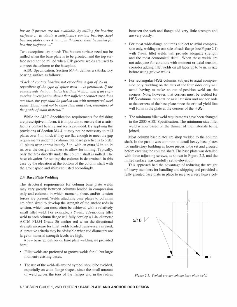
• For most wide-flange columns subject to axial compres-sion only, welding on one side of each flange (see Figure 2.1) with c-in. fillet welds will provide adequate strength and the most economical detail. When these welds are not adequate for columns with moment or axial tension, consider adding fillet welds on all faces up to w in. in size before using groove welds.
• For rectangular HSS columns subject to axial compres-sion only, welding on the flats of the four sides only will avoid having to make an out-of-position weld on the corners. Note, however, that corners must be welded for HSS columns moment or axial tension and anchor rods at the corners of the base plate since the critical yield line will form in the plate at the corners of the HSS.
• The minimum fillet weld requirements have been changed in the 2005 AISC Specification. The minimum-size fillet weld is now based on the thinner of the materials being joined.
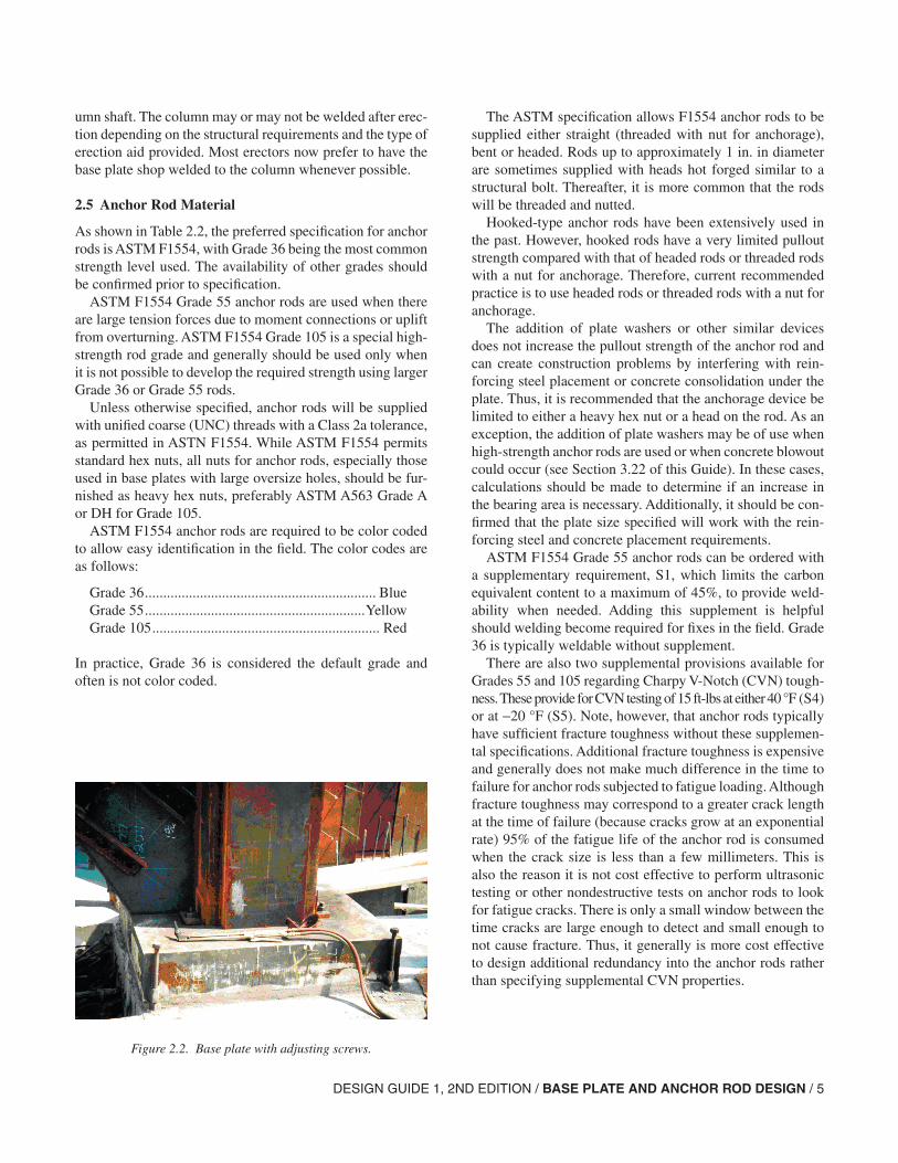
Most column base plates are shop welded to the column shaft. In the past it was common to detail heavy base plates for multi-story building as loose pieces to be set and grouted before erecting the column shaft. The base plate was detailed with three adjusting screws, as shown in Figure 2.2, and the milled surface was carefully set to elevation.
This approach had the advantage of reducing the weight of heavy members for handling and shipping and provided a fully grouted base plate in place to receive a very heavy col-
Figure 2.1. Typical gravity column base plate weld.
DESIGN GUIDE 1, 2ND EDITION / BASE PLATE AND ANCHOR ROD DESIGN / 5
umn shaft. The column may or may not be welded after erec-tion depending on the structural requirements and the type of erection aid provided. Most erectors now prefer to have the base plate shop welded to the column whenever possible.
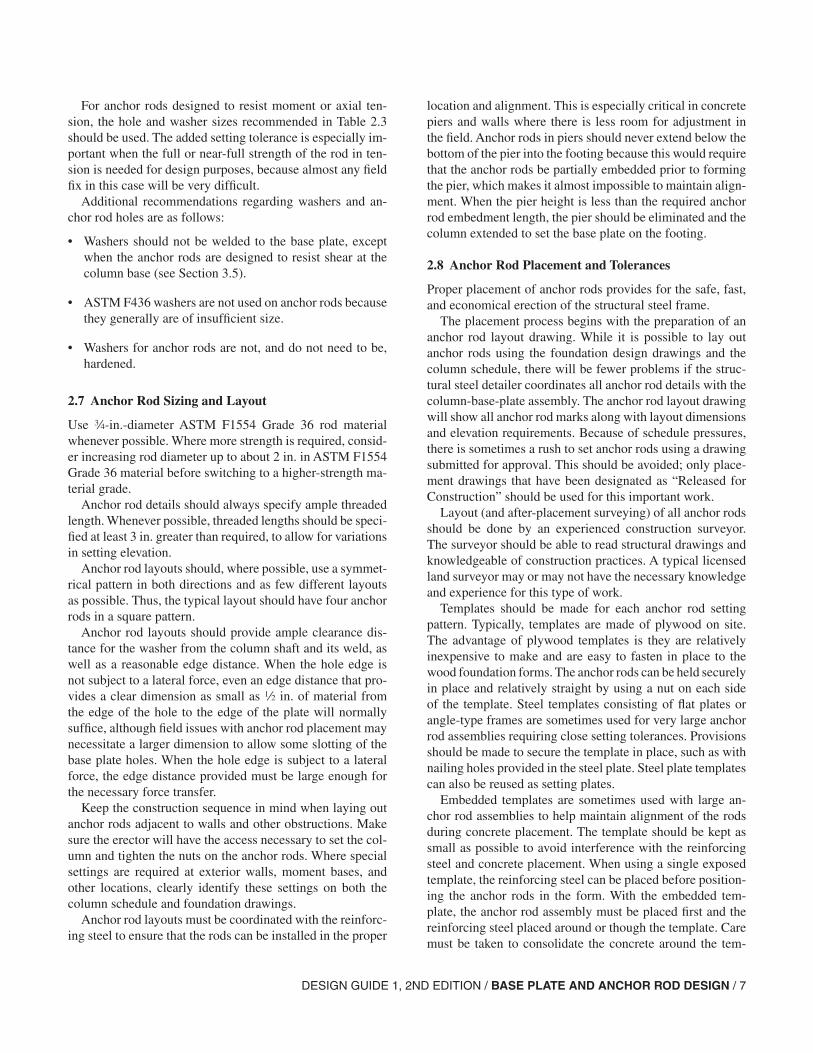
2.5 Anchor Rod Material
As shown in Table 2.2, the preferred specification for anchor rods is ASTM F1554, with Grade 36 being the most common strength level used. The availability of other grades should be confirmed prior to specification.
ASTM F1554 Grade 55 anchor rods are used when there are large tension forces due to moment connections or uplift from overturning. ASTM F1554 Grade 105 is a special high-strength rod grade and generally should be used only when it is not possible to develop the required strength using larger Grade 36 or Grade 55 rods.
Unless otherwise specified, anchor rods will be supplied with unified coarse (UNC) threads with a Class 2a tolerance, as permitted in ASTN F1554. While ASTM F1554 permits standard hex nuts, all nuts for anchor rods, especially those used in base plates with large oversize holes, should be fur-nished as heavy hex nuts, preferably ASTM A563 Grade A or DH for Grade 105.
ASTM F1554 anchor rods are required to be color coded to allow easy identification in the field. The color codes are as follows:
Grade 36 ............................................................... BlueGrade 55 ............................................................YellowGrade 105 .............................................................. Red
In practice, Grade 36 is considered the default grade and often is not color coded.
The ASTM specification allows F1554 anchor rods to be supplied either straight (threaded with nut for anchorage), bent or headed. Rods up to approximately 1 in. in diameter are sometimes supplied with heads hot forged similar to a structural bolt. Thereafter, it is more common that the rods will be threaded and nutted.
Hooked-type anchor rods have been extensively used in the past. However, hooked rods have a very limited pullout strength compared with that of headed rods or threaded rods with a nut for anchorage. Therefore, current recommended practice is to use headed rods or threaded rods with a nut for anchorage.
The addition of plate washers or other similar devices does not increase the pullout strength of the anchor rod and can create construction problems by interfering with rein-forcing steel placement or concrete consolidation under the plate. Thus, it is recommended that the anchorage device be limited to either a heavy hex nut or a head on the rod. As an exception, the addition of plate washers may be of use when high-strength anchor rods are used or when concrete blowout could occur (see Section 3.22 of this Guide). In these cases, calculations should be made to determine if an increase in the bearing area is necessary. Additionally, it should be con-firmed that the plate size specified will work with the rein-forcing steel and concrete placement requirements.
ASTM F1554 Grade 55 anchor rods can be ordered with a supplementary requirement, S1, which limits the carbon equivalent content to a maximum of 45%, to provide weld-ability when needed. Adding this supplement is helpful should welding become required for fixes in the field. Grade 36 is typically weldable without supplement.
There are also two supplemental provisions available for Grades 55 and 105 regarding Charpy V-Notch (CVN) tough-ness. These provide for CVN testing of 15 ft-lbs at either 40 °F (S4) or at −20 °F (S5). Note, however, that anchor rods typically have sufficient fracture toughness without these supplemen-tal specifications. Additional fracture toughness is expensive and generally does not make much difference in the time to failure for anchor rods subjected to fatigue loading. Although fracture toughness may correspond to a greater crack length at the time of failure (because cracks grow at an exponential rate) 95% of the fatigue life of the anchor rod is consumed when the crack size is less than a few millimeters. This is also the reason it is not cost effective to perform ultrasonic testing or other nondestructive tests on anchor rods to look for fatigue cracks. There is only a small window between the time cracks are large enough to detect and small enough to not cause fracture. Thus, it generally is more cost effective to design additional redundancy into the anchor rods rather than specifying supplemental CVN properties.
Figure 2.2. Base plate with adjusting screws.
6 / DESIGN GUIDE 1, 2ND EDITION / BASE PLATE AND ANCHOR ROD DESIGN
Galvanized anchor rods are often used when the column-base-plate assembly is exposed and subject to corrosion. Either the hot-dip galvanizing process (ASTM 153) or the mechanical galvanizing process (ASTM B695) is allowed in ASTM F1554; however, all threaded components of the fastener assembly must be galvanized by the same process. Mixing of rods galvanized by one process and nuts by an-other may result in an unworkable assembly. It is recom-mended that galvanized anchor rods and nuts be purchased from the same supplier and shipped preassembled. Because this is not an ASTM requirement, this should be specified on the contract documents.
Note also that galvanizing increases friction between the nut and the rod and even though the nuts are over tapped, special lubrication may be required.
ASTM A449, A36 and A307 specifications are listed in Table 2.2 for comparison purposes, because some suppliers are more familiar with these specifications. Note that ASTM F1554 grades match up closely with many aspects of these older material specifications. Note also that these older ma-terial specifications contain almost none of the anchor rod specific requirements found in ASTM F1554.
Drilled-in epoxy-type anchor rods are discussed in sev-eral places in this Design Guide. This category of anchor rod does not include wedge-type mechanical anchors, which are not recommended for anchor rods because they must be ten-sioned to securely lock in the wedge device. Column move-ment during erection can cause wedge-type anchor rods to loosen.
2.6 Anchor Rod Holes and Washers
The most common field problem is anchor rod placements that either do not fit within the anchor rod hole pattern or
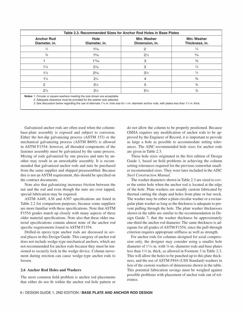
do not allow the column to be properly positioned. Because OSHA requires any modification of anchor rods to be ap-proved by the Engineer of Record, it is important to provide as large a hole as possible to accommodate setting toler-ances. The AISC-recommended hole sizes for anchor rods are given in Table 2.3.
These hole sizes originated in the first edition of Design Guide 1, based on field problems in achieving the column setting tolerances required for the previous somewhat small-er recommended sizes. They were later included in the AISC Steel Construction Manual.
The washer diameters shown in Table 2.3 are sized to cov-er the entire hole when the anchor rod is located at the edge of the hole. Plate washers are usually custom fabricated by thermal cutting the shape and holes from plate or bar stock. The washer may be either a plain circular washer or a rectan-gular plate washer as long as the thickness is adequate to pre-vent pulling through the hole. The plate washer thicknesses shown in the table are similar to the recommendation in De-sign Guide 7, that the washer thickness be approximately one-third the anchor rod diameter. The same thickness is ad-equate for all grades of ASTM F1554, since the pull-through criterion requires appropriate stiffness as well as strength.
For anchor rods for columns designed for axial compres-sion only, the designer may consider using a smaller hole diameter of 1z in. with w-in.-diameter rods and base plates less than 14 in. thick, as allowed in Footnote 3 in Table 2.3. This will allow the holes to be punched up to this plate thick-ness, and the use of ASTM F844 (USS Standard) washers in lieu of the custom washers of dimensions shown in the table. This potential fabrication savings must be weighed against possible problems with placement of anchor rods out of tol-erance.
Table 2.3. Recommended Sizes for Anchor Rod Holes in Base Plates
Anchor RodDiameter, in.
HoleDiameter, in.
Min. WasherDimension, in.
Min. WasherThickness, in.
w 1c 2
d 1b 2 c
1 1m 3 a
1 2z 3
1 2c 3
1w 2w 4 s
2 3 5 w
2 3 5 d
Notes: 1. Circular or square washers meeting the size shown are acceptable. 2. Adequate clearance must be provided for the washer size selected. 3. See discussion below regarding the use of alternate 1z-in. hole size for w-in.-diameter anchor rods, with plates less than 1 in. thick.
DESIGN GUIDE 1, 2ND EDITION / BASE PLATE AND ANCHOR ROD DESIGN / 7
For anchor rods designed to resist moment or axial ten-sion, the hole and washer sizes recommended in Table 2.3 should be used. The added setting tolerance is especially im-portant when the full or near-full strength of the rod in ten-sion is needed for design purposes, because almost any field fix in this case will be very difficult.
Additional recommendations regarding washers and an-chor rod holes are as follows:
• Washers should not be welded to the base plate, except when the anchor rods are designed to resist shear at the column base (see Section 3.5).
• ASTM F436 washers are not used on anchor rods because they generally are of insufficient size.
• Washers for anchor rods are not, and do not need to be, hardened.
2.7 Anchor Rod Sizing and Layout
Use w-in.-diameter ASTM F1554 Grade 36 rod material whenever possible. Where more strength is required, consid-er increasing rod diameter up to about 2 in. in ASTM F1554 Grade 36 material before switching to a higher-strength ma-terial grade.
Anchor rod details should always specify ample threaded length. Whenever possible, threaded lengths should be speci-fied at least 3 in. greater than required, to allow for variations in setting elevation.
Anchor rod layouts should, where possible, use a symmet-rical pattern in both directions and as few different layouts as possible. Thus, the typical layout should have four anchor rods in a square pattern.
Anchor rod layouts should provide ample clearance dis-tance for the washer from the column shaft and its weld, as well as a reasonable edge distance. When the hole edge is not subject to a lateral force, even an edge distance that pro-vides a clear dimension as small as 2 in. of material from the edge of the hole to the edge of the plate will normally suffice, although field issues with anchor rod placement may necessitate a larger dimension to allow some slotting of the base plate holes. When the hole edge is subject to a lateral force, the edge distance provided must be large enough for the necessary force transfer.
Keep the construction sequence in mind when laying out anchor rods adjacent to walls and other obstructions. Make sure the erector will have the access necessary to set the col-umn and tighten the nuts on the anchor rods. Where special settings are required at exterior walls, moment bases, and other locations, clearly identify these settings on both the column schedule and foundation drawings.
Anchor rod layouts must be coordinated with the reinforc-ing steel to ensure that the rods can be installed in the proper
location and alignment. This is especially critical in concrete piers and walls where there is less room for adjustment in the field. Anchor rods in piers should never extend below the bottom of the pier into the footing because this would require that the anchor rods be partially embedded prior to forming the pier, which makes it almost impossible to maintain align-ment. When the pier height is less than the required anchor rod embedment length, the pier should be eliminated and the column extended to set the base plate on the footing.
2.8 Anchor Rod Placement and Tolerances
Proper placement of anchor rods provides for the safe, fast, and economical erection of the structural steel frame.
The placement process begins with the preparation of an anchor rod layout drawing. While it is possible to lay out anchor rods using the foundation design drawings and the column schedule, there will be fewer problems if the struc-tural steel detailer coordinates all anchor rod details with the column-base-plate assembly. The anchor rod layout drawing will show all anchor rod marks along with layout dimensions and elevation requirements. Because of schedule pressures, there is sometimes a rush to set anchor rods using a drawing submitted for approval. This should be avoided; only place-ment drawings that have been designated as “Released for Construction” should be used for this important work.
Layout (and after-placement surveying) of all anchor rods should be done by an experienced construction surveyor. The surveyor should be able to read structural drawings and knowledgeable of construction practices. A typical licensed land surveyor may or may not have the necessary knowledge and experience for this type of work.
Templates should be made for each anchor rod setting pattern. Typically, templates are made of plywood on site. The advantage of plywood templates is they are relatively inexpensive to make and are easy to fasten in place to the wood foundation forms. The anchor rods can be held securely in place and relatively straight by using a nut on each side of the template. Steel templates consisting of flat plates or angle-type frames are sometimes used for very large anchor rod assemblies requiring close setting tolerances. Provisions should be made to secure the template in place, such as with nailing holes provided in the steel plate. Steel plate templates can also be reused as setting plates.
Embedded templates are sometimes used with large an-chor rod assemblies to help maintain alignment of the rods during concrete placement. The template should be kept as small as possible to avoid interference with the reinforcing steel and concrete placement. When using a single exposed template, the reinforcing steel can be placed before position-ing the anchor rods in the form. With the embedded tem-plate, the anchor rod assembly must be placed first and the reinforcing steel placed around or though the template. Care must be taken to consolidate the concrete around the tem-
8 / DESIGN GUIDE 1, 2ND EDITION / BASE PLATE AND ANCHOR ROD DESIGN
plate to eliminate voids. This is especially important if the template serves as part of the anchorage.
When the templates are removed, the anchor rods should be surveyed and grid lines marked on each setting. The an-chor rods should then be cleaned and checked to make sure the nuts can be easily turned and that the vertical alignment is proper. If necessary, the threads should be lubricated. OSHA requires the contractor to review the settings and notify the Engineer of Record of any anchor rods that will not meet the tolerance required for the hole size specified.
As exceptions to the forgoing recommendations, fast-track projects and projects with complex layouts may require spe-cial considerations. In a fast-track project, the steel design and detailing may lag behind the initial foundation work and the structural layout changed as the job progresses. A project with complex layouts may be such that even the most ac-curate placement possible of anchor rods in concrete forms does not facilitate proper fit-up. On these projects, it may be better to use special drilled-in epoxy-type anchor rods rather than cast-in-place rods.
For fast-track projects, this has the advantage of allowing the foundation work to start without waiting for anchor rods and anchor rod layout drawings. For complex layouts, this has the advantage of providing easier and more accurate an-chor rod layout for more accurate column erection.
Coordination of AISC anchor rod setting tolerances and ACI tolerances for embedded items can be an issue. ACI 117-90, Section 2.3, Placement of embedded items, allows a tolerance on vertical, lateral, and level alignment of ±1 in. AISC Code of Standard Practice (AISC, 2005), Section 7.5.1, lists the following tolerances:
“(a) The variation in dimension between the centers of any two Anchor Rods within an Anchor-Rod Group shall be equal to or less than 8 in.”
“(b) The variation in dimension between the centers of ad-jacent Anchor-Rod Groups shall be equal to or less than 4 in.”
“(c) The variation in elevation of the tops of Anchor Rods shall be equal to or less than plus or minus 2 in.”
“(d) The accumulated variation in dimension between cen-ters of Anchor-Rod Groups along the Established Column Line through multiple Anchor-Rod Groups shall be equal to or less than 4 in. per 100 ft, but not to exceed a total of 1 in.”
“(e) The variation in dimension from the center of any An-chor-Rod Group to the Established Column Line through that group shall be equal to or less than 4 in.”
Thus, ACI 117 is much more generous for embedded items than the AISC Code of Standard Practice (AISC, 2005) is for anchor rod tolerances. Furthermore, since each trade will work to their own industry standard unless the contract documents require otherwise, it is recommended that the project specifications, typically CSI Division 3, require that the anchor rods be set in accordance with the AISC Code of Standard Practice (AISC, 2005) tolerance requirements, in order to clearly establish a basis for acceptance of the anchor rods. It may be helpful to actually list the tolerance require-ments instead of simply providing a reference.
2.9 Column Erection Procedures
OSHA requires the general contractor to notify the erector in writing that the anchor rods are ready for start of steel erection. This notice is intended to ensure that the layout has been checked, any required repairs have been made, and the concrete has achieved the required strength. The erector then, depending on project requirements, rechecks the layout and sets elevations for each column base.
There are three common methods of setting elevations: setting nuts and washers, setting plates, and shim stacks. Project requirements and local custom generally determine which of these methods is used. It is important in all methods that the erector tighten all of the anchor rods before remov-ing the erection load line so that the nut and washer are tight against the base plate. This is not intended to induce any level of pretension, but rather to ensure that the anchor rod assembly is firm enough to prevent column base movement during erection. If it is necessary to loosen the nuts to adjust column plumb, care should be taken to adequately brace the column while the adjustment is made.
2.9.1. Setting Nut and Washer Method
The use of four anchor rods has made the setting nut and washer method of column erection very popular, as it is easy and cost effective. Once the setting nuts and washers are set to elevation, there is little chance they will be dis-turbed. The four-rod layout provides a stable condition for erection, especially if the anchor rods are located outside of the column area. The elevation and plumbness of the column can be adjusted using the nuts. When designing anchor rods using setting nuts and sashers, it is important to remember these rods are also loaded in compression and their strength should be checked for push out at the bottom of the footing. It is recommended that use of the setting nut and washer method be limited to columns that are relatively lightly loaded during erection. Even after the base plate is grouted, the setting nut will transfer load to the anchor rod, and this should be considered when selecting the method to set the column elevation.
DESIGN GUIDE 1, 2ND EDITION / BASE PLATE AND ANCHOR ROD DESIGN / 9
2.9.2 Setting Plate Method
Setting plates (sometimes called leveling plates) are a very positive method for setting column base elevations but are somewhat more costly than setting nuts and washers.
Setting plates are usually about 4 in. thick and slightly larger than the base plate. Because a plate this thin has a ten-dency to warp when fabricated, setting plates are typically limited to a maximum dimension of about 24 in.
If the setting plate is also to be used as a template, the holes are made z in. larger than the anchor rod diameter. Otherwise, standard anchor rod hole sizes are used.
After the anchor rods have been set, the setting plate is removed and the anchor rods are checked as noted earlier. The bearing area is then cleaned, and the elevations are set using either jam nuts or shims. Grout is spread over the area, and the setting plate tapped down to elevation. The elevation should be rechecked after the plate is set to verify that it is correct. If necessary, the plate and grout can be removed and the process started over.
One problem with using setting plates is that warping in either the setting plate or the base plate, or column move-ment during “bolt-up,” may result in gaps between the set-ting plate and base plate. Generally, there will still be ade-quate bearing and the amount of column settlement required to close the gap will not be detrimental to the structure. The acceptability of any gaps can be determined using the provi-sions in AISC Specification Section M4.4.
Setting plates provide a positive check on anchor rod settings prior to the start of erection and provide the most stable erection base for the column. The use of setting plates should be considered when the column is being erected in an excavation where water and soil may wash under the base plate and make cleaning and grouting difficult after the col-umn is erected.
2.9.3 Shim Stack Method
Column erection on steel shim stacks is a traditional method for setting base plate elevations that has the advantage that all compression is transferred from the base plate to the foundation without involving the anchor rods. Steel shim packs, approximately 4 in. wide, are set at the four edges of the base plate. The areas of the shim stacks are typically large enough to carry substantial dead load prior to grouting of the base plate.
2.9.4 Setting Large Base Plates
Base plate size and weight may be such that the base plate must be preset to receive the column. When crane capaci-ties or handling requirements make it advantageous to set the plate in advance of the column, the plates are furnished with either wedge-type shims or leveling or adjusting screws
to allow them to be set to elevation and grouted before the column is set, as illustrated in Figure 2.2. Leveling-screw assemblies consist of sleeve nuts welded to the sides of the plate and a threaded rod screw that can be adjusted. These plates should be furnished with hole sizes as shown in Table 2.3. The column shaft should be detailed with stools or erection aids, as required. Where possible, the column attachment to the base plate should avoid field welding because of the dif-ficulty in preheating a heavy base plate for welding.
2.10 Grouting Requirements
Grout serves as the connection between the steel base plate and the concrete foundation to transfer compression loads. Accordingly, it is important that the grout be properly de-signed and placed in a proper and timely manner.
Grout should have a design compressive strength at least twice the strength of the foundation concrete. This will be adequate to transfer the maximum steel bearing pressure to the foundation. The design thickness of the grout space will depend on how fluid the grout is and how accurate the eleva-tion of the top of concrete is placed. If the column is set on a finished floor, a 1-in. space may be adequate, while on the top of a footing or pier, normally the space should be 12 in. to 2 in. Large base plates and plates with shear lugs may require more space.
Grout holes are not required for most base plates. For plates 24 in. or less in width, a form can be set up and the grout can be forced in from one side until it flows out the op-posite side. When plates become larger or when shear lugs are used, it is recommended that one or two grout holes be provided. Grout holes are typically 2 to 3 in. in diameter and are typically thermally cut in the base plate. A form should be provided around the edge, and some sort of filling device should be used to provide enough head pressure to cause the grout to flow out to all of the sides.
It is important to follow the manufacturer’s recommen-dations for mixing and curing times. When placing grout in cold weather, make sure protection is provided per the manufacturer’s specification.
Grouting is an interface between trades that provides a challenge for the specification writer. Typically, the grout is furnished by the concrete or general contractor, but the tim-ing is essential to the work of the steel erector. Because of this, specification writers sometimes place grouting in the steel section. This only confuses the issue because the erec-tor then has to make arrangements with the concrete contrac-tor to do the grouting. Grouting should be the responsibility of the concrete contractor, and there should be a requirement to grout column bases promptly when notified by the erector that the column is in its final location.
10 / DESIGN GUIDE 1, 2ND EDITION / BASE PLATE AND ANCHOR ROD DESIGN
2.11 Anchor Rod Repairs
Anchor rods may require repair or modification during installation or later on in service. OSHA requires that any modification of anchor rods during construction be reviewed and approved by the Engineer of Record. On a case-by-case basis, the Engineer of Record must evaluate the relative mer-its of a proposed repair as opposed to rejecting the foundation and requiring the contractor to replace part of the foundation with new anchor rods per the original design.
Records should be kept of the repair procedure and the re-sults. The Engineer of Record may require special inspection or testing deemed necessary to verify the repair.
Most of these repairs are standard simple modifications that do not require calculations. The most common anchor rod problems are addressed in the following sections.
2.11.1 Anchor Rods in the Wrong Position
For anchor rods in the wrong position, the repair method depends on the nature of the problem and when in the con-struction process it is first noted. Is the repair required for only one rod or for the entire pattern of rods? How far out of position is the rod or pattern, and what are the required strengths of the rods?
If the error is discovered before the column base plate has been fabricated, it might be possible to use a different pattern or even a different base plate. If the rod positions interfere with the column shaft, it may be necessary to modify the col-umn shaft by cutting and reinforcing sections of the flange or web.
If one or two rods in a pattern are misplaced after the col-umn has been fabricated and shipped, the most common re-pair is to slot the base plate and use a plate washer to span the slot. If the entire pattern is off uniformly, it might be possible to cut the base plate off and offset the base plate to accommodate the out of tolerance. It is necessary to check the base plate design for this eccentricity. When removing the base plate, it may be required to turn the plate over to have a clean surface on which to weld the column shaft.
If the anchor rod or rods are more than a couple of inches out of position, the best solution may be to cut off the exist-ing rods and install new drilled-in epoxy-type anchor rods. When using such rods, carefully follow the manufacturer’s recommendations and provide inspection as required in the applicable building code. Locate the holes to avoid reinforc-ing steel in the foundation. If any reinforcing steel is cut, a check of the effect on foundation strength should be made.
2.11.2 Anchor Rods Bent or Not Vertical
Care should be taken when setting anchor rods to ensure they are plumb. If the rods are not properly secured in the template, or if there is reinforcing steel interference, the rods
may end up at an angle to the vertical that will not allow the base plate to be fit over the rods.
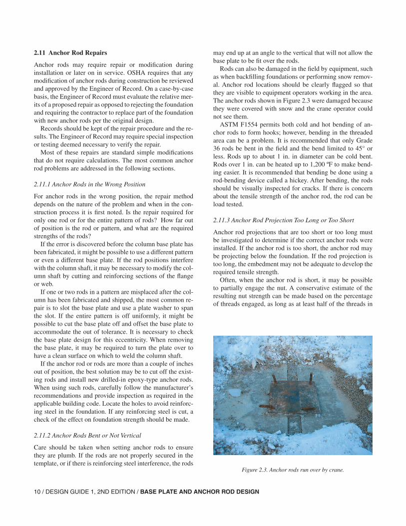
Rods can also be damaged in the field by equipment, such as when backfilling foundations or performing snow remov-al. Anchor rod locations should be clearly flagged so that they are visible to equipment operators working in the area. The anchor rods shown in Figure 2.3 were damaged because they were covered with snow and the crane operator could not see them.
ASTM F1554 permits both cold and hot bending of an-chor rods to form hooks; however, bending in the threaded area can be a problem. It is recommended that only Grade 36 rods be bent in the field and the bend limited to 45° or less. Rods up to about 1 in. in diameter can be cold bent. Rods over 1 in. can be heated up to 1,200 ºF to make bend-ing easier. It is recommended that bending be done using a rod-bending device called a hickey. After bending, the rods should be visually inspected for cracks. If there is concern about the tensile strength of the anchor rod, the rod can be load tested.
2.11.3 Anchor Rod Projection Too Long or Too Short
Anchor rod projections that are too short or too long must be investigated to determine if the correct anchor rods were installed. If the anchor rod is too short, the anchor rod may be projecting below the foundation. If the rod projection is too long, the embedment may not be adequate to develop the required tensile strength.
Often, when the anchor rod is short, it may be possible to partially engage the nut. A conservative estimate of the resulting nut strength can be made based on the percentage of threads engaged, as long as at least half of the threads in
Figure 2.3. Anchor rods run over by crane.
DESIGN GUIDE 1, 2ND EDITION / BASE PLATE AND ANCHOR ROD DESIGN / 11
the nut are engaged. Welding the nut to the anchor rod is not a prequalified welded joint and is not recommended.
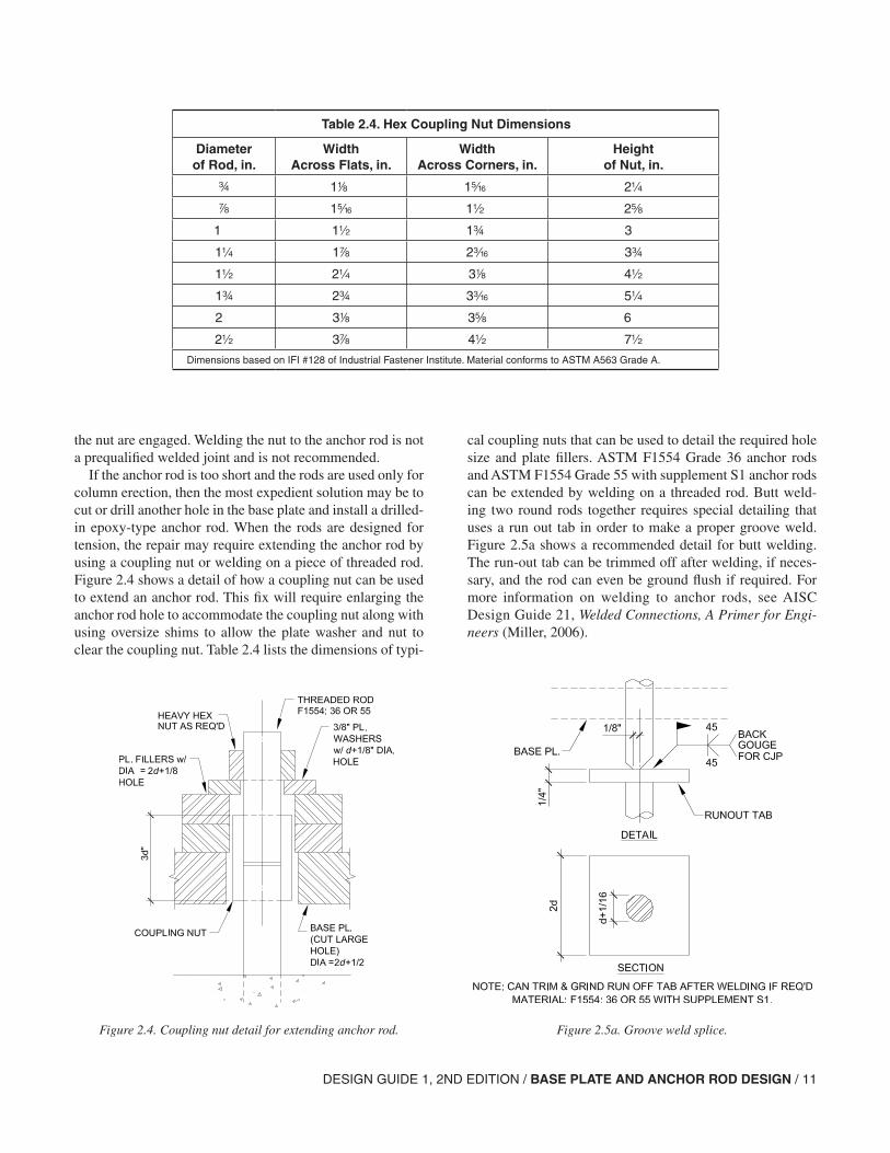
If the anchor rod is too short and the rods are used only for column erection, then the most expedient solution may be to cut or drill another hole in the base plate and install a drilled-in epoxy-type anchor rod. When the rods are designed for tension, the repair may require extending the anchor rod by using a coupling nut or welding on a piece of threaded rod. Figure 2.4 shows a detail of how a coupling nut can be used to extend an anchor rod. This fix will require enlarging the anchor rod hole to accommodate the coupling nut along with using oversize shims to allow the plate washer and nut to clear the coupling nut. Table 2.4 lists the dimensions of typi-
cal coupling nuts that can be used to detail the required hole size and plate fillers. ASTM F1554 Grade 36 anchor rods and ASTM F1554 Grade 55 with supplement S1 anchor rods can be extended by welding on a threaded rod. Butt weld-ing two round rods together requires special detailing that uses a run out tab in order to make a proper groove weld. Figure 2.5a shows a recommended detail for butt welding. The run-out tab can be trimmed off after welding, if neces-sary, and the rod can even be ground flush if required. For more information on welding to anchor rods, see AISC Design Guide 21, Welded Connections, A Primer for Engi-neers (Miller, 2006).
Figure 2.4. Coupling nut detail for extending anchor rod.
Table 2.4. Hex Coupling Nut Dimensions
Diameterof Rod, in.
WidthAcross Flats, in.
WidthAcross Corners, in.
Heightof Nut, in.
w 18 1c 2
d 1c 1 2s
1 1 1w 3
1 1d 2x 3w
1 2 38 4
1w 2w 3x 5
2 38 3s 6
2 3d 4 7
Dimensions based on IFI #128 of Industrial Fastener Institute. Material conforms to ASTM A563 Grade A.
Figure 2.5a. Groove weld splice.
12 / DESIGN GUIDE 1, 2ND EDITION / BASE PLATE AND ANCHOR ROD DESIGN
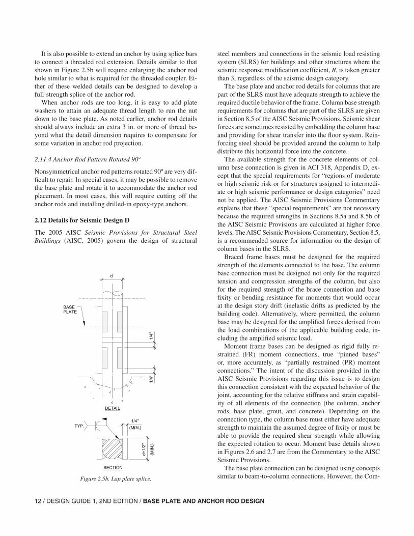
It is also possible to extend an anchor by using splice bars to connect a threaded rod extension. Details similar to that shown in Figure 2.5b will require enlarging the anchor rod hole similar to what is required for the threaded coupler. Ei-ther of these welded details can be designed to develop a full-strength splice of the anchor rod.
When anchor rods are too long, it is easy to add plate washers to attain an adequate thread length to run the nut down to the base plate. As noted earlier, anchor rod details should always include an extra 3 in. or more of thread be-yond what the detail dimension requires to compensate for some variation in anchor rod projection.
2.11.4 Anchor Rod Pattern Rotated 90°
Nonsymmetrical anchor rod patterns rotated 90º are very dif-ficult to repair. In special cases, it may be possible to remove the base plate and rotate it to accommodate the anchor rod placement. In most cases, this will require cutting off the anchor rods and installing drilled-in epoxy-type anchors.
2.12 Details for Seismic Design D
The 2005 AISC Seismic Provisions for Structural Steel Buildings (AISC, 2005) govern the design of structural
steel members and connections in the seismic load resisting system (SLRS) for buildings and other structures where the seismic response modification coefficient, R, is taken greater than 3, regardless of the seismic design category.
The base plate and anchor rod details for columns that are part of the SLRS must have adequate strength to achieve the required ductile behavior of the frame. Column base strength requirements for columns that are part of the SLRS are given in Section 8.5 of the AISC Seismic Provisions. Seismic shear forces are sometimes resisted by embedding the column base and providing for shear transfer into the floor system. Rein-forcing steel should be provided around the column to help distribute this horizontal force into the concrete.
The available strength for the concrete elements of col-umn base connection is given in ACI 318, Appendix D, ex-cept that the special requirements for “regions of moderate or high seismic risk or for structures assigned to intermedi-ate or high seismic performance or design categories” need not be applied. The AISC Seismic Provisions Commentary explains that these “special requirements” are not necessary because the required strengths in Sections 8.5a and 8.5b of the AISC Seismic Provisions are calculated at higher force levels. The AISC Seismic Provisions Commentary, Section 8.5, is a recommended source for information on the design of column bases in the SLRS.
Braced frame bases must be designed for the required strength of the elements connected to the base. The column base connection must be designed not only for the required tension and compression strengths of the column, but also for the required strength of the brace connection and base fixity or bending resistance for moments that would occur at the design story drift (inelastic drifts as predicted by the building code). Alternatively, where permitted, the column base may be designed for the amplified forces derived from the load combinations of the applicable building code, in-cluding the amplified seismic load.
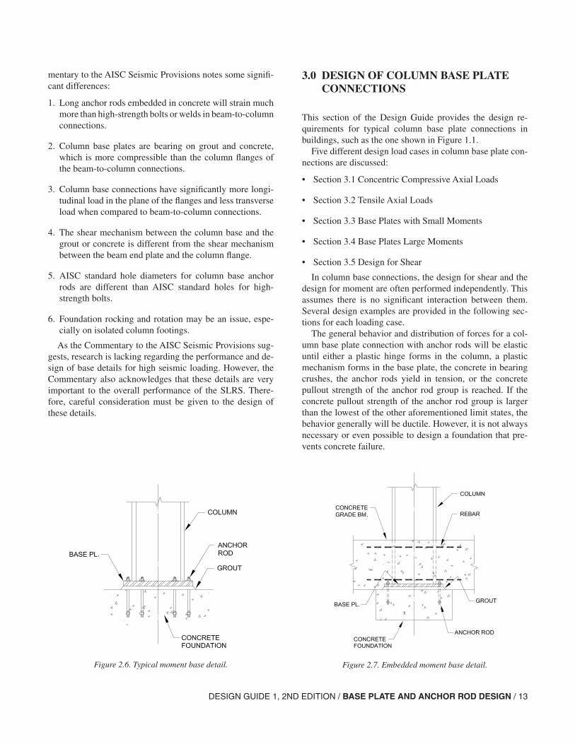
Moment frame bases can be designed as rigid fully re-strained (FR) moment connections, true “pinned bases” or, more accurately, as “partially restrained (PR) moment connections.” The intent of the discussion provided in the AISC Seismic Provisions regarding this issue is to design this connection consistent with the expected behavior of the joint, accounting for the relative stiffness and strain capabil-ity of all elements of the connection (the column, anchor rods, base plate, grout, and concrete). Depending on the connection type, the column base must either have adequate strength to maintain the assumed degree of fixity or must be able to provide the required shear strength while allowing the expected rotation to occur. Moment base details shown in Figures 2.6 and 2.7 are from the Commentary to the AISC Seismic Provisions.
The base plate connection can be designed using concepts similar to beam-to-column connections. However, the Com-Figure 2.5b. Lap plate splice.
DESIGN GUIDE 1, 2ND EDITION / BASE PLATE AND ANCHOR ROD DESIGN / 13
mentary to the AISC Seismic Provisions notes some signifi-cant differences:
1. Long anchor rods embedded in concrete will strain much more than high-strength bolts or welds in beam-to-column connections.
2. Column base plates are bearing on grout and concrete, which is more compressible than the column flanges of the beam-to-column connections.
3. Column base connections have significantly more longi-tudinal load in the plane of the flanges and less transverse load when compared to beam-to-column connections.
4. The shear mechanism between the column base and the grout or concrete is different from the shear mechanism between the beam end plate and the column flange.
5. AISC standard hole diameters for column base anchor rods are different than AISC standard holes for high-strength bolts.
6. Foundation rocking and rotation may be an issue, espe-cially on isolated column footings.
As the Commentary to the AISC Seismic Provisions sug-gests, research is lacking regarding the performance and de-sign of base details for high seismic loading. However, the Commentary also acknowledges that these details are very important to the overall performance of the SLRS. There-fore, careful consideration must be given to the design of these details.
3.0 DESIGN OF COLUMN BASE PLATE CONNECTIONS
This section of the Design Guide provides the design re-quirements for typical column base plate connections in buildings, such as the one shown in Figure 1.1.
Five different design load cases in column base plate con-nections are discussed:
• Section 3.1 Concentric Compressive Axial Loads
• Section 3.2 Tensile Axial Loads
• Section 3.3 Base Plates with Small Moments
• Section 3.4 Base Plates Large Moments
• Section 3.5 Design for Shear
In column base connections, the design for shear and the design for moment are often performed independently. This assumes there is no significant interaction between them. Several design examples are provided in the following sec-tions for each loading case.
The general behavior and distribution of forces for a col-umn base plate connection with anchor rods will be elastic until either a plastic hinge forms in the column, a plastic mechanism forms in the base plate, the concrete in bearing crushes, the anchor rods yield in tension, or the concrete pullout strength of the anchor rod group is reached. If the concrete pullout strength of the anchor rod group is larger than the lowest of the other aforementioned limit states, the behavior generally will be ductile. However, it is not always necessary or even possible to design a foundation that pre-vents concrete failure.
Figure 2.6. Typical moment base detail. Figure 2.7. Embedded moment base detail.
14 / DESIGN GUIDE 1, 2ND EDITION / BASE PLATE AND ANCHOR ROD DESIGN
For example, in statically loaded structures, if the strength is much larger than the demand, the ductility is not necessary and it is acceptable to design with the limit state of tensile or shear strength of the anchor rod group governing the design. However, frames designed for seismic lateral load resistance are expected to behave in a ductile manner and, in this case, it may be necessary to design the foundation and the col-umn-base-plate connection so that the concrete limit states of tensile or shear strength of the anchor rod group do not govern the design. See ACI Appendix D, Section D3.3.4.
OSHA Requirements
The regulations of the Occupational Safety and Health Ad-ministration (OSHA) Safety Standards for Steel Erection (OSHA, 2001) require a minimum of four anchor rods in column-base-plate connections. The requirements exclude post-type columns that weigh less than 300 lb. Columns, base plates, and their foundations must have sufficient mo-ment strength to resist a minimum eccentric gravity load of 300 lb located 18 in. from the extreme outer face of the column in each direction.
The OSHA criteria can be met with even the smallest of anchor rods on a 4-in. × 4-in. pattern. If one considers only the moments from the eccentric loads (since including the gravity loads results in no tensile force in the anchor rods), and the resisting force couple is taken as the design force of the two bolts times a 4-in. lever arm, the design moment strength for w-in. anchor rods equals (2)(19.1 kips)(4 in.) = 306 kip-in. For a 14-in.-deep column, the OSHA required moment strength is only (1.6)(0.300)(18 + 7) = 12.0 kip-in.
3.1. Concentric Compressive Axial Loads
When a column base resists only compressive column axial loads, the base plate must be large enough to resist the bear-ing forces transferred from the base plate (concrete bearing limit), and the base plate must be of sufficient thickness (base plate yielding limit).
3.1.1 Concrete Bearing Limit
The design bearing strength on concrete is defined in ACI 318-02, Section 10.17, as φ(0.85fc′A1) when the sup-porting surface is not larger than the base plate. When the supporting surface is wider on all sides than the loaded area, the design bearing strength above is permitted to be multi-plied by A A2 1 ≤ 2.
The 2005 AISC Specification, Section J8, provides the nominal bearing strength, Pp, as follows:
Equation J8-1:
Pp = 0.85fc′A1 on the full area of a concrete support.
Equation J8-2:
These equations are multiplied by the resistance factor, φ, for LRFD or divided by the safety factor, Ω, for ASD. Section J8 stipulates the φ and Ω factors (in the absence of Code Regulations) for bearing on concrete as follows:
φ = 0.60 (LRFD) Ω = 2.50 (ASD)
Alternatively, ACI 318-02 stipulates a φ factor of 0.65 for bearing on concrete. This apparent conflict exists due to an oversight in the AISC Specification development process. The authors recommend the use of the ACI-specified φ fac-tor in designing column base plates.
The nominal bearing strength can be converted to a stress format by dividing out the area term Pp equations such that,
On the full area of a concrete support:
fp(max) = 0.85 fc′When the concrete base is larger than the loaded area on
all four sides:
The conversion of the generic nominal pressure to an LRFD or ASD available bearing stress is
fpu(max) = φ fp(max) (LRFD)
The concrete bearing strength is a function of the concrete compressive strength, and the ratio of geometrically similar concrete area to base plate area, as indicated in Section 10.17 of ACI 318 (ACI, 2002), as follows:
where
fp(max) = maximum concrete bearing stress, ksi
φ = strength reduction factor for bearing, 0.65 per Section 9.3, ACI 318-02
fc′ = specified compressive strength of concrete, ksi
P f AA
Af Ap c c= ′( )
≤ ′0 85 1 71
2
11. .
f fA
Afp c c(max) . .= ′( )
≤ ′0 85 1 72
1
ff
pap
(max)(max)=Ω
(ASD)
f fcA
Ap(max) .= ′( )φ 0 85 2
1
A
A2
1
2≤
DESIGN GUIDE 1, 2ND EDITION / BASE PLATE AND ANCHOR ROD DESIGN / 15
A1 = area of the base plate, in.2
A2 = maximum area of the portion of the supporting surface that is geometrically similar to and con-centric with the loaded area, in.2
The increase of the concrete bearing capacity associated with the term A A2 1 accounts for the beneficial effects of the concrete confinement. Note that A2 is the largest area that is geometrically similar to (having the same aspect ratio as) the base plate and can be inscribed on the horizontal top surface of the concrete footing, pier, or beam without going beyond the edges of the concrete.
There is a limit to the beneficial effects of confinement, which is reflected by the limit on A2 (to a maximum of four times A1) or by the inequality limit. Thus, for a column base plate bearing on a footing far from edges or openings, A A2 1 2= . = 2.
The bearing stress on the concrete must not be greater than fp(max):
Thus,
When A2 = A1, the required minimum base plate area can be determined as
When A2 ≥ 4A1, the required minimum base plate area can be determined as
Many column base plates bear directly on a layer of grout. Because, the grout compressive strength is always specified higher than the concrete strength—the authors recommend that the grout strength be specified as two times the concrete strength—it is conservative to use the concrete compressive strength for fc′ in the above equations.
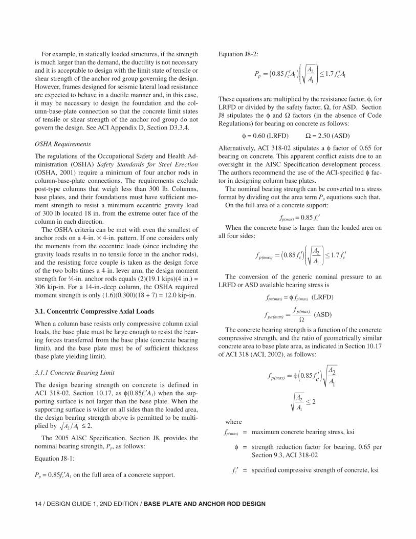
The important dimensions of the column-base plate con-nection are shown in Figure 3.1.1.
3.1.2 Base Plate Yielding Limit (W-Shapes)
For axially loaded base plates, the bearing stress under the base plate is assumed uniformly distributed and can be ex-pressed as
This bearing pressure causes bending in the base plate at the assumed critical sections shown in Figure 3.1.1(b). This
P
Afu
pu1
≤ (max) (LRFD)
P
Afa
pa1
≤ (max) (ASD)
AP
frequ
pu1( )
(max)
= (LRFD)
AP
freqa
pa1( )
(max)
= (ASD)
AP
frequ
c1 0 85( ) .
=′φ (LRFD)
AP
freqa
c1 0 85( ) .
=′
Ω (ASD)
AP
frequ
c1
1
2 0 85( ) .=
′
φ (LRFD)
AP
freqa
c1
1
2 0 85( ) .=
′
Ω (ASD)
Figure 3.1.1. Design of base plate with axial compressive load.
fP
BNpuu= (LRFD)
fP
BNpaa= (ASD)
16 / DESIGN GUIDE 1, 2ND EDITION / BASE PLATE AND ANCHOR ROD DESIGN
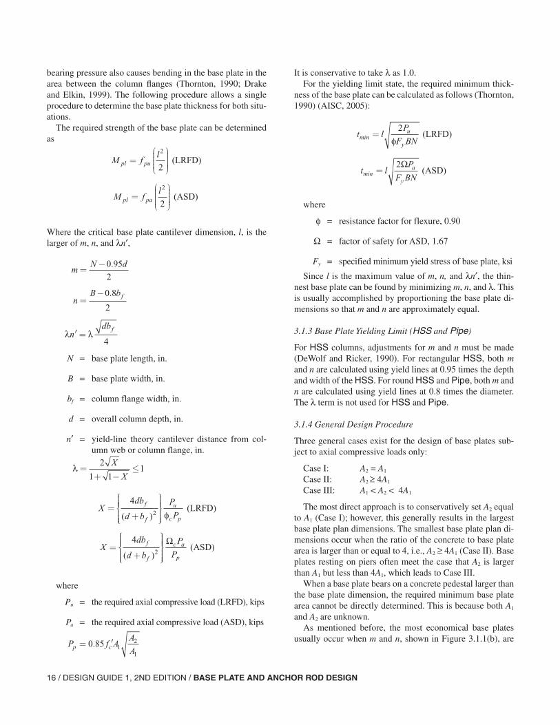
bearing pressure also causes bending in the base plate in the area between the column flanges (Thornton, 1990; Drake and Elkin, 1999). The following procedure allows a single procedure to determine the base plate thickness for both situ-ations.
The required strength of the base plate can be determined as
Where the critical base plate cantilever dimension, l, is the larger of m, n, and λn′,
N = base plate length, in.
B = base plate width, in.
bf = column flange width, in.
d = overall column depth, in.
n′ = yield-line theory cantilever distance from col-umn web or column flange, in.
where
Pu = the required axial compressive load (LRFD), kips
Pa = the required axial compressive load (ASD), kips
It is conservative to take λ as 1.0.For the yielding limit state, the required minimum thick-
ness of the base plate can be calculated as follows (Thornton, 1990) (AISC, 2005):
where
φ = resistance factor for flexure, 0.90
Ω = factor of safety for ASD, 1.67
Fy = specified minimum yield stress of base plate, ksi
Since l is the maximum value of m, n, and λn′, the thin-nest base plate can be found by minimizing m, n, and λ. This is usually accomplished by proportioning the base plate di-mensions so that m and n are approximately equal.
3.1.3 Base Plate Yielding Limit (HSS and Pipe)
For HSS columns, adjustments for m and n must be made (DeWolf and Ricker, 1990). For rectangular HSS, both m and n are calculated using yield lines at 0.95 times the depth and width of the HSS. For round HSS and Pipe, both m and n are calculated using yield lines at 0.8 times the diameter. The λ term is not used for HSS and Pipe.
3.1.4 General Design Procedure
Three general cases exist for the design of base plates sub-ject to axial compressive loads only:
Case I: A2 = A1
Case II: A2 ≥ 4A1
Case III: A1 < A2 < 4A1
The most direct approach is to conservatively set A2 equal to A1 (Case I); however, this generally results in the largest base plate plan dimensions. The smallest base plate plan di-mensions occur when the ratio of the concrete to base plate area is larger than or equal to 4, i.e., A2 ≥ 4A1 (Case II). Base plates resting on piers often meet the case that A2 is larger than A1 but less than 4A1, which leads to Case III.
When a base plate bears on a concrete pedestal larger than the base plate dimension, the required minimum base plate area cannot be directly determined. This is because both A1 and A2 are unknown.
As mentioned before, the most economical base plates usually occur when m and n, shown in Figure 3.1.1(b), are
M fl
pl pu=
2
2 (LRFD)
M fl
pl pa=
2
2 (ASD)
mN d
=−0 95
2
.
nB bf=−0 8
2
.
λ λ′ =ndbf
4
λ =+ −
≤2
1 11
X
X
Xdb
d b
P
Pf
f
u
c p
=+
42( ) φ
(LRFD)
Xdb
d b
P
Pf
f
c a
p
=+
42( )
Ω (ASD)
P f AA
Ap c= ′0 85 12
1
.
t lP
F BNu
ymin =
2
φ (LRFD)
t lP
F BNa
ymin =
2Ω (ASD)
DESIGN GUIDE 1, 2ND EDITION / BASE PLATE AND ANCHOR ROD DESIGN / 17
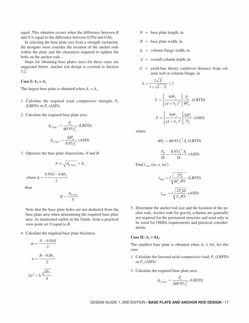
equal. This situation occurs when the difference between B and N is equal to the difference between 0.95d and 0.8bf.
In selecting the base plate size from a strength viewpoint, the designer must consider the location of the anchor rods within the plate and the clearances required to tighten the bolts on the anchor rods.
Steps for obtaining base plates sizes for these cases are suggested below. Anchor rod design is covered in Section 3.2.
Case I: A2 = A1
The largest base plate is obtained when A2 = A1.
1. Calculate the required axial compressive strength, Pu (LRFD) or Pa (ASD).
2. Calculate the required base plate area.
3. Optimize the base plate dimensions, N and B.
then
Note that the base plate holes are not deducted from the base plate area when determining the required base plate area. As mentioned earlier in the Guide, from a practical view point set N equal to B.
4. Calculate the required base plate thickness.
N = base plate length, in.
B = base plate width, in.
bf = column flange width, in.
d = overall column depth, in.
n′ = yield-line theory cantilever distance from col-umn web or column flange, in.
where
Find l max (m, n, λn′)
5. Determine the anchor rod size and the location of the an-chor rods. Anchor rods for gravity columns are generally not required for the permanent structure and need only to be sized for OSHA requirements and practical consider-ations.
Case II: A2 ≥ 4A1
The smallest base plate is obtained when A2 ≥ 4A1 for this case.
1. Calculate the factored axial compressive load, Pu (LRFD) or Pa (ASD).
2. Calculate the required base plate area.
AP
frequ
c1 0 85( ) .
=′φ (LRFD)
AP
freqa
c1 0 85( ) .
=′
Ω (ASD)
N A req≈ +1( ) ∆
where ∆ =−0 95 0 8
2
. .d bf
BA
Nreq= 1( )
mN d
=−0 95
2
.
nB bf=−0 8
2
.
λ λ′ =ndbf
4
λ =+ −
≤2
1 11
X
X
Xdb
d b
P
Pf
f
u
p
=+
42( ) φ
(LRFD)
Xdb
d b
P
Pf
f
a
p
=+
42( )
Ω (ASD)
φ φP f AP c= ′0 85 1. (LRFD)
P f AP c
Ω Ω=
′0 85 1. (ASD)
t lP
F BNu
ymin =
2
φ (LRFD)
t lP
F BNa
ymin =
2 Ω (ASD)
AP
frequ
c1 2 0 85( ) .
=′φ (LRFD)
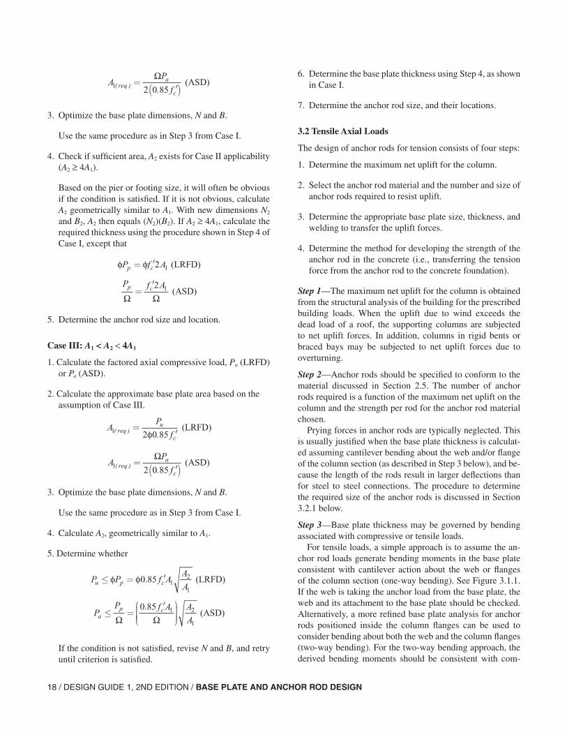
18 / DESIGN GUIDE 1, 2ND EDITION / BASE PLATE AND ANCHOR ROD DESIGN
3. Optimize the base plate dimensions, N and B.
Use the same procedure as in Step 3 from Case I.
4. Check if sufficient area, A2 exists for Case II applicability (A2 ≥ 4A1).
Based on the pier or footing size, it will often be obvious if the condition is satisfied. If it is not obvious, calculate A2 geometrically similar to A1. With new dimensions N2 and B2, A2 then equals (N2)(B2). If A2 ≥ 4A1, calculate the required thickness using the procedure shown in Step 4 of Case I, except that
5. Determine the anchor rod size and location.
Case III: A1 < A2 < 4A1
1. Calculate the factored axial compressive load, Pu (LRFD) or Pa (ASD).
2. Calculate the approximate base plate area based on the assumption of Case III.
3. Optimize the base plate dimensions, N and B.
Use the same procedure as in Step 3 from Case I.
4. Calculate A2, geometrically similar to A1.
5. Determine whether
If the condition is not satisfied, revise N and B, and retry until criterion is satisfied.
6. Determine the base plate thickness using Step 4, as shown in Case I.
7. Determine the anchor rod size, and their locations.
3.2 Tensile Axial Loads
The design of anchor rods for tension consists of four steps:
1. Determine the maximum net uplift for the column.
2. Select the anchor rod material and the number and size of anchor rods required to resist uplift.
3. Determine the appropriate base plate size, thickness, and welding to transfer the uplift forces.
4. Determine the method for developing the strength of the anchor rod in the concrete (i.e., transferring the tension force from the anchor rod to the concrete foundation).
Step 1—The maximum net uplift for the column is obtained from the structural analysis of the building for the prescribed building loads. When the uplift due to wind exceeds the dead load of a roof, the supporting columns are subjected to net uplift forces. In addition, columns in rigid bents or braced bays may be subjected to net uplift forces due to overturning.
Step 2—Anchor rods should be specified to conform to the material discussed in Section 2.5. The number of anchor rods required is a function of the maximum net uplift on the column and the strength per rod for the anchor rod material chosen.
Prying forces in anchor rods are typically neglected. This is usually justified when the base plate thickness is calculat-ed assuming cantilever bending about the web and/or flange of the column section (as described in Step 3 below), and be-cause the length of the rods result in larger deflections than for steel to steel connections. The procedure to determine the required size of the anchor rods is discussed in Section 3.2.1 below.
Step 3—Base plate thickness may be governed by bending associated with compressive or tensile loads.
For tensile loads, a simple approach is to assume the an-chor rod loads generate bending moments in the base plate consistent with cantilever action about the web or flanges of the column section (one-way bending). See Figure 3.1.1. If the web is taking the anchor load from the base plate, the web and its attachment to the base plate should be checked. Alternatively, a more refined base plate analysis for anchor rods positioned inside the column flanges can be used to consider bending about both the web and the column flanges (two-way bending). For the two-way bending approach, the derived bending moments should be consistent with com-
AP
freqa
c1 2 0 85( ) .
=′( )
Ω (ASD)
φ φP f Ap c= ′2 1 (LRFD)
P f Ap c
Ω Ω=′2 1 (ASD)
AP
frequ
c1 2 0 85( ) .
=′φ (LRFD)
AP
freqa
c1 2 0 85( ) .
=′( )
Ω (ASD)
P P f AA
Au p c≤ = ′φ φ0 85 12
1
. (LRFD)
PP f A A
Aap c≤ =
′
Ω Ω
0 85 1 2
1
. (ASD)
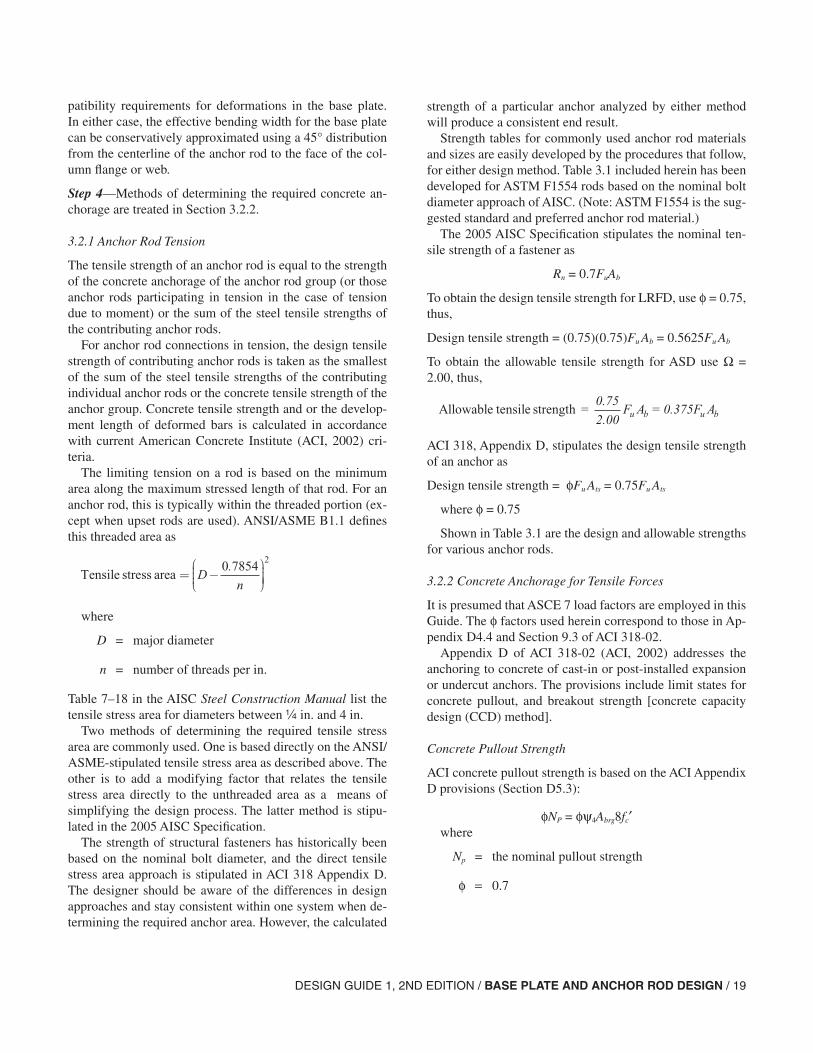
DESIGN GUIDE 1, 2ND EDITION / BASE PLATE AND ANCHOR ROD DESIGN / 19
patibility requirements for deformations in the base plate. In either case, the effective bending width for the base plate can be conservatively approximated using a 45° distribution from the centerline of the anchor rod to the face of the col-umn flange or web.
Step 4—Methods of determining the required concrete an-chorage are treated in Section 3.2.2.
3.2.1 Anchor Rod Tension
The tensile strength of an anchor rod is equal to the strength of the concrete anchorage of the anchor rod group (or those anchor rods participating in tension in the case of tension due to moment) or the sum of the steel tensile strengths of the contributing anchor rods.
For anchor rod connections in tension, the design tensile strength of contributing anchor rods is taken as the smallest of the sum of the steel tensile strengths of the contributing individual anchor rods or the concrete tensile strength of the anchor group. Concrete tensile strength and or the develop-ment length of deformed bars is calculated in accordance with current American Concrete Institute (ACI, 2002) cri-teria.
The limiting tension on a rod is based on the minimum area along the maximum stressed length of that rod. For an anchor rod, this is typically within the threaded portion (ex-cept when upset rods are used). ANSI/ASME B1.1 defines this threaded area as
where
D = major diameter
n = number of threads per in.
Table 7–18 in the AISC Steel Construction Manual list the tensile stress area for diameters between in. and 4 in.
Two methods of determining the required tensile stress area are commonly used. One is based directly on the ANSI/ASME-stipulated tensile stress area as described above. The other is to add a modifying factor that relates the tensile stress area directly to the unthreaded area as a means of simplifying the design process. The latter method is stipu-lated in the 2005 AISC Specification.
The strength of structural fasteners has historically been based on the nominal bolt diameter, and the direct tensile stress area approach is stipulated in ACI 318 Appendix D. The designer should be aware of the differences in design approaches and stay consistent within one system when de-termining the required anchor area. However, the calculated
strength of a particular anchor analyzed by either method will produce a consistent end result.
Strength tables for commonly used anchor rod materials and sizes are easily developed by the procedures that follow, for either design method. Table 3.1 included herein has been developed for ASTM F1554 rods based on the nominal bolt diameter approach of AISC. (Note: ASTM F1554 is the sug-gested standard and preferred anchor rod material.)
The 2005 AISC Specification stipulates the nominal ten-sile strength of a fastener as
Rn = 0.7FuAb
To obtain the design tensile strength for LRFD, use φ = 0.75, thus,
Design tensile strength = (0.75)(0.75)Fu Ab = 0.5625Fu Ab
To obtain the allowable tensile strength for ASD use Ω = 2.00, thus,
ACI 318, Appendix D, stipulates the design tensile strength of an anchor as
Design tensile strength = φFu Ats = 0.75Fu Ats
where φ = 0.75
Shown in Table 3.1 are the design and allowable strengths for various anchor rods.
3.2.2 Concrete Anchorage for Tensile Forces
It is presumed that ASCE 7 load factors are employed in this Guide. The φ factors used herein correspond to those in Ap-pendix D4.4 and Section 9.3 of ACI 318-02.
Appendix D of ACI 318-02 (ACI, 2002) addresses the anchoring to concrete of cast-in or post-installed expansion or undercut anchors. The provisions include limit states for concrete pullout, and breakout strength [concrete capacity design (CCD) method].
Concrete Pullout Strength
ACI concrete pullout strength is based on the ACI Appendix D provisions (Section D5.3):
φNP = φψ4Abrg8fc′where
Np = the nominal pullout strength
φ = 0.7
Tensile stress area = −
D
n
0 78542
.
Allowable tensile strength = 0.75
2.00= 0.375F A F Au b u b
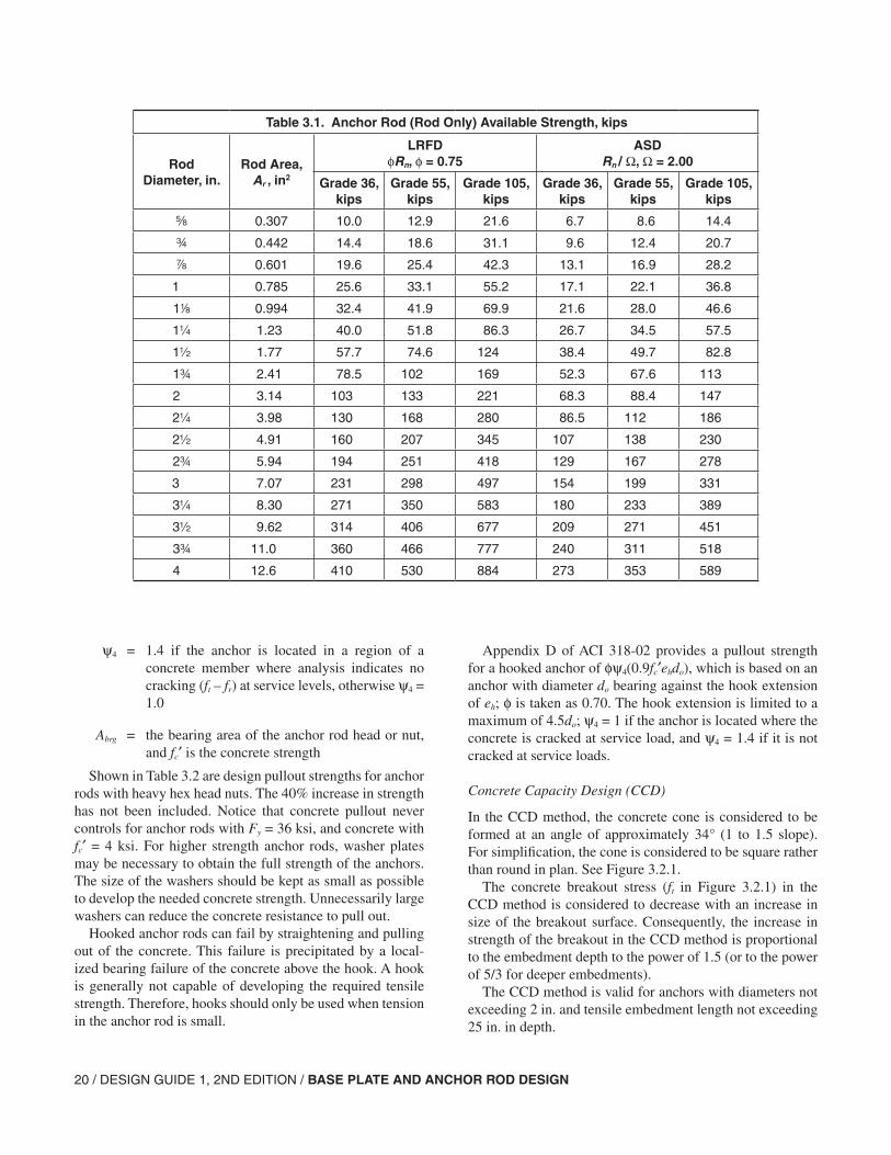
20 / DESIGN GUIDE 1, 2ND EDITION / BASE PLATE AND ANCHOR ROD DESIGN
Table 3.1. Anchor Rod (Rod Only) Available Strength, kips
Rod Diameter, in.
Rod Area, Ar , in2
LRFDφRn, φ = 0.75
ASDRn / Ω, Ω = 2.00
Grade 36,kips
Grade 55,kips
Grade 105,kips
Grade 36,kips
Grade 55,kips
Grade 105,kips
s 0.307 10.0 12.9 21.6 6.7 8.6 14.4
w 0.442 14.4 18.6 31.1 9.6 12.4 20.7
d 0.601 19.6 25.4 42.3 13.1 16.9 28.2
1 0.785 25.6 33.1 55.2 17.1 22.1 36.8
18 0.994 32.4 41.9 69.9 21.6 28.0 46.6
1 1.23 40.0 51.8 86.3 26.7 34.5 57.5
1 1.77 57.7 74.6 124 38.4 49.7 82.8
1w 2.41 78.5 102 169 52.3 67.6 113
2 3.14 103 133 221 68.3 88.4 147
2 3.98 130 168 280 86.5 112 186
2 4.91 160 207 345 107 138 230
2w 5.94 194 251 418 129 167 278
3 7.07 231 298 497 154 199 331
3 8.30 271 350 583 180 233 389
3 9.62 314 406 677 209 271 451
3w 11.0 360 466 777 240 311 518
4 12.6 410 530 884 273 353 589
ψ4 = 1.4 if the anchor is located in a region of a concrete member where analysis indicates no cracking (ft – fr) at service levels, otherwise ψ4 = 1.0
Abrg = the bearing area of the anchor rod head or nut, and fc′ is the concrete strength
Shown in Table 3.2 are design pullout strengths for anchor rods with heavy hex head nuts. The 40% increase in strength has not been included. Notice that concrete pullout never controls for anchor rods with Fy = 36 ksi, and concrete with fc′ = 4 ksi. For higher strength anchor rods, washer plates may be necessary to obtain the full strength of the anchors. The size of the washers should be kept as small as possible to develop the needed concrete strength. Unnecessarily large washers can reduce the concrete resistance to pull out.
Hooked anchor rods can fail by straightening and pulling out of the concrete. This failure is precipitated by a local-ized bearing failure of the concrete above the hook. A hook is generally not capable of developing the required tensile strength. Therefore, hooks should only be used when tension in the anchor rod is small.
Appendix D of ACI 318-02 provides a pullout strength for a hooked anchor of φψ4(0.9fc′ehdo), which is based on an anchor with diameter do bearing against the hook extension of eh; φ is taken as 0.70. The hook extension is limited to a maximum of 4.5do; ψ4 = 1 if the anchor is located where the concrete is cracked at service load, and ψ4 = 1.4 if it is not cracked at service loads.
Concrete Capacity Design (CCD)
In the CCD method, the concrete cone is considered to be formed at an angle of approximately 34° (1 to 1.5 slope). For simplification, the cone is considered to be square rather than round in plan. See Figure 3.2.1.
The concrete breakout stress (ft in Figure 3.2.1) in the CCD method is considered to decrease with an increase in size of the breakout surface. Consequently, the increase in strength of the breakout in the CCD method is proportional to the embedment depth to the power of 1.5 (or to the power of 5/3 for deeper embedments).
The CCD method is valid for anchors with diameters not exceeding 2 in. and tensile embedment length not exceeding 25 in. in depth.
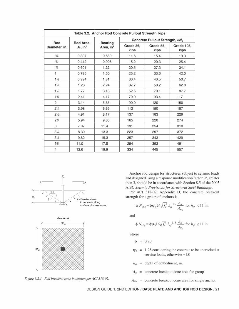
DESIGN GUIDE 1, 2ND EDITION / BASE PLATE AND ANCHOR ROD DESIGN / 21
Anchor rod design for structures subject to seismic loads and designed using a response modification factor, R, greater than 3, should be in accordance with Section 8.5 of the 2005 AISC Seismic Provisions for Structural Steel Buildings.
Per ACI 318-02, Appendix D, the concrete breakout strength for a group of anchors is
and
where
φ = 0.70
ψ3 = 1.25 considering the concrete to be uncracked at service loads, otherwise =1.0
hef = depth of embedment, in.
AN = concrete breakout cone area for group
ANo = concrete breakout cone area for single anchor
Table 3.2. Anchor Rod Concrete Pullout Strength, kips
Rod Diameter, in.
Rod Area, Ar, in2
Bearing Area, in2
Concrete Pullout Strength, φNp
Grade 36,kips
Grade 55,kips
Grade 105,kips
s 0.307 0.689 11.6 15.4 19.3
w 0.442 0.906 15.2 20.3 25.4
d 0.601 1.22 20.5 27.3 34.1
1 0.785 1.50 25.2 33.6 42.0
18 0.994 1.81 30.4 40.5 50.7
1 1.23 2.24 37.7 50.2 62.8
1 1.77 3.13 52.6 70.1 87.7
1w 2.41 4.17 70.0 93.4 117
2 3.14 5.35 90.0 120 150
2 3.98 6.69 112 150 187
2 4.91 8.17 137 183 229
2w 5.94 9.80 165 220 274
3 7.07 11.4 191 254 318
3 8.30 13.3 223 297 372
3 9.62 15.3 257 343 429
3w 11.0 17.5 294 393 491
4 12.6 19.9 334 445 557
Figure 3.2.1. Full breakout cone in tension per ACI 318-02.
φ φψ = for in.3N f hA
Ahcbg c ef
N
Noef24 111 5′ <.
φ φψ = for in.3N f hA
Ahcbg c ef
N
Noef16 115 3′ ≥/
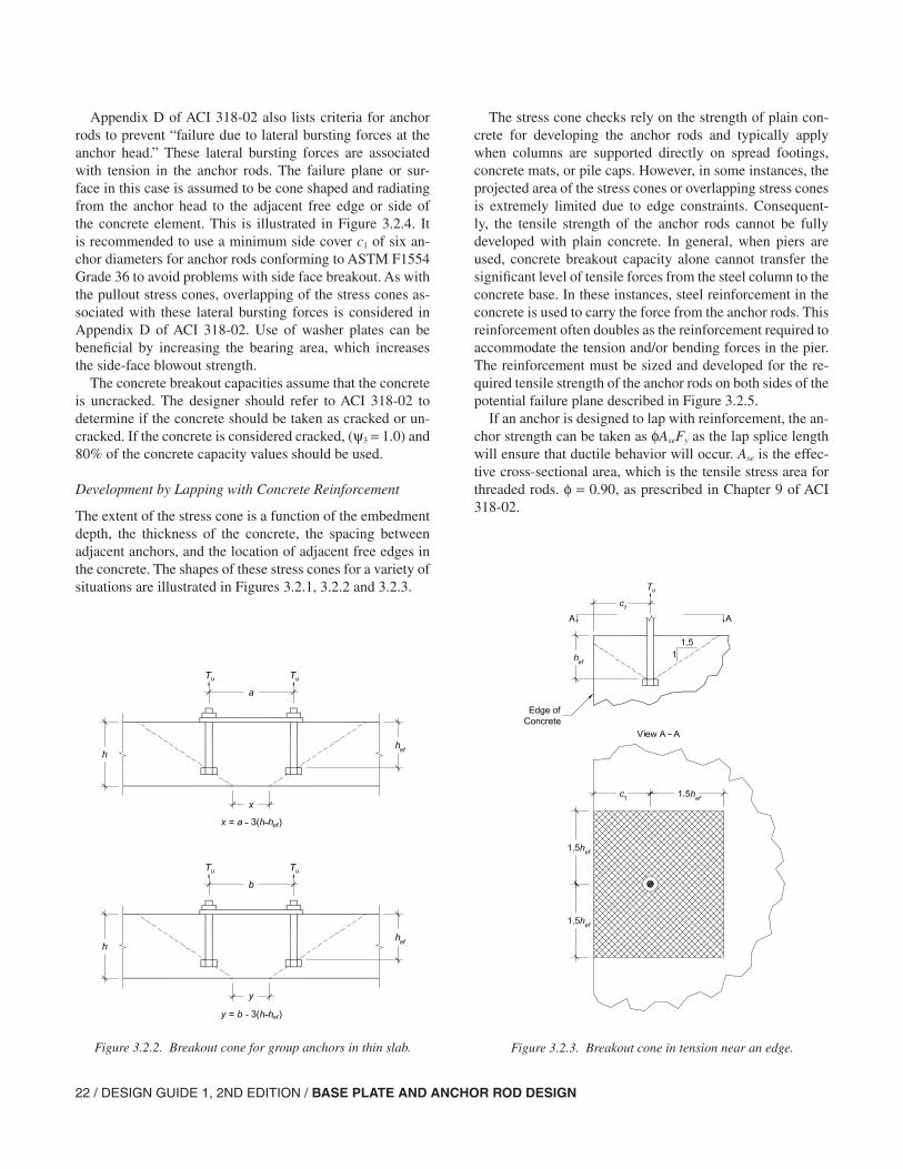
22 / DESIGN GUIDE 1, 2ND EDITION / BASE PLATE AND ANCHOR ROD DESIGN
Appendix D of ACI 318-02 also lists criteria for anchor rods to prevent “failure due to lateral bursting forces at the anchor head.” These lateral bursting forces are associated with tension in the anchor rods. The failure plane or sur-face in this case is assumed to be cone shaped and radiating from the anchor head to the adjacent free edge or side of the concrete element. This is illustrated in Figure 3.2.4. It is recommended to use a minimum side cover c1 of six an-chor diameters for anchor rods conforming to ASTM F1554 Grade 36 to avoid problems with side face breakout. As with the pullout stress cones, overlapping of the stress cones as-sociated with these lateral bursting forces is considered in Appendix D of ACI 318-02. Use of washer plates can be beneficial by increasing the bearing area, which increases the side-face blowout strength.
The concrete breakout capacities assume that the concrete is uncracked. The designer should refer to ACI 318-02 to determine if the concrete should be taken as cracked or un-cracked. If the concrete is considered cracked, (ψ3 = 1.0) and 80% of the concrete capacity values should be used.
Development by Lapping with Concrete Reinforcement
The extent of the stress cone is a function of the embedment depth, the thickness of the concrete, the spacing between adjacent anchors, and the location of adjacent free edges in the concrete. The shapes of these stress cones for a variety of situations are illustrated in Figures 3.2.1, 3.2.2 and 3.2.3.
The stress cone checks rely on the strength of plain con-crete for developing the anchor rods and typically apply when columns are supported directly on spread footings, concrete mats, or pile caps. However, in some instances, the projected area of the stress cones or overlapping stress cones is extremely limited due to edge constraints. Consequent-ly, the tensile strength of the anchor rods cannot be fully developed with plain concrete. In general, when piers are used, concrete breakout capacity alone cannot transfer the significant level of tensile forces from the steel column to the concrete base. In these instances, steel reinforcement in the concrete is used to carry the force from the anchor rods. This reinforcement often doubles as the reinforcement required to accommodate the tension and/or bending forces in the pier. The reinforcement must be sized and developed for the re-quired tensile strength of the anchor rods on both sides of the potential failure plane described in Figure 3.2.5.
If an anchor is designed to lap with reinforcement, the an-chor strength can be taken as φAseFy as the lap splice length will ensure that ductile behavior will occur. Ase is the effec-tive cross-sectional area, which is the tensile stress area for threaded rods. φ = 0.90, as prescribed in Chapter 9 of ACI 318-02.
Figure 3.2.2. Breakout cone for group anchors in thin slab. Figure 3.2.3. Breakout cone in tension near an edge.
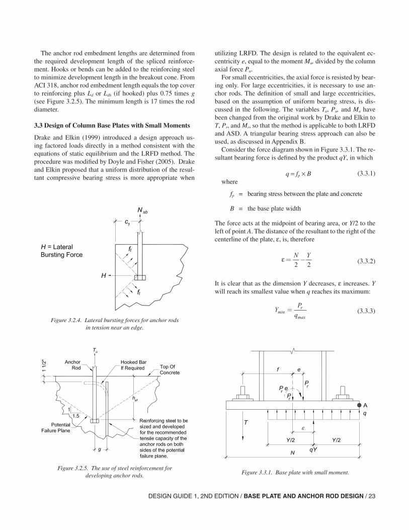
DESIGN GUIDE 1, 2ND EDITION / BASE PLATE AND ANCHOR ROD DESIGN / 23
The anchor rod embedment lengths are determined from the required development length of the spliced reinforce-ment. Hooks or bends can be added to the reinforcing steel to minimize development length in the breakout cone. From ACI 318, anchor rod embedment length equals the top cover to reinforcing plus Ld or Ldh (if hooked) plus 0.75 times g (see Figure 3.2.5). The minimum length is 17 times the rod diameter.
3.3 Design of Column Base Plates with Small Moments
Drake and Elkin (1999) introduced a design approach us-ing factored loads directly in a method consistent with the equations of static equilibrium and the LRFD method. The procedure was modified by Doyle and Fisher (2005). Drake and Elkin proposed that a uniform distribution of the resul-tant compressive bearing stress is more appropriate when
utilizing LRFD. The design is related to the equivalent ec-centricity e, equal to the moment Mu, divided by the column axial force Pu.
For small eccentricities, the axial force is resisted by bear-ing only. For large eccentricities, it is necessary to use an-chor rods. The definition of small and large eccentricities, based on the assumption of uniform bearing stress, is dis-cussed in the following. The variables Tu, Pu, and Mu have been changed from the original work by Drake and Elkin to T, Pr, and Mr, so that the method is applicable to both LRFD and ASD. A triangular bearing stress approach can also be used, as discussed in Appendix B.
Consider the force diagram shown in Figure 3.3.1. The re-sultant bearing force is defined by the product qY, in which
q = fp × Bwhere
fp = bearing stress between the plate and concrete
B = the base plate width
The force acts at the midpoint of bearing area, or Y/2 to the left of point A. The distance of the resultant to the right of the centerline of the plate, ε, is, therefore
It is clear that as the dimension Y decreases, ε increases. Y will reach its smallest value when q reaches its maximum:
Figure 3.2.4. Lateral bursting forces for anchor rods in tension near an edge.
Figure 3.2.5. The use of steel reinforcement for developing anchor rods. Figure 3.3.1. Base plate with small moment.
(3.3.1)
ε= −N Y
2 2 (3.3.2)
YP
qr
minmax
= (3.3.3)

24 / DESIGN GUIDE 1, 2ND EDITION / BASE PLATE AND ANCHOR ROD DESIGN
where
q = fp(max) × B
The expression, for the location of the resultant bearing force given in Equation 3.3.2 shows that ε reaches its maximum value when Y is minimum. Therefore
For moment equilibrium, the line of action of the applied load, Pu, and that of the bearing force, qY must coincide; that is, e = ε.
If the eccentricity
exceeds the maximum value that ε can attain, the applied loads cannot be resisted by bearing alone and anchor rods will be in tension.
In summary, for values of e less than εmax, Y is greater than Ymin and q is less than qmax, and obviously, fp is less than fp(max). For values of e greater than εmax, q = qmax. Thus, a critical value of eccentricity of the applied load combination is
When analyzing various load and plate configurations, in case e ≤ ecrit, there will be no tendency to overturn, anchor rods are not required for moment equilibrium, and the force combination will be considered to have a small moment. On the other hand, if e > ecrit, moment equilibrium cannot be maintained by bearing alone and anchor rods are required. Such combinations of axial load and moment are referred to as large moment cases. The design of plates with large mo-ments is outlined in Section 3.4.
3.3.1 Concrete Bearing Stress
The concrete bearing stress is assumed to be uniformly dis-tributed over the area Y × B. Equation 3.3.2, for the case of e = ε, provides an expression for the length of bearing area, Y:
therefore,
Y = N − (2)(e)
The bearing stress can then be determined as
for the small moment case, e ≤ ecrit. Therefore, as noted above, q ≤ qmax. From Equations 3.3.1 and 3.3.4, it follows that fp ≤ fp(max).
For the condition e = ecrit, the bearing length, Y, obtained by use of Equations 3.3.7 and 3.3.8 is
3.3.2 Base Plate Flexural Yielding Limit at Bearing Interface
The bearing pressure between the concrete and the base plate will cause bending in the base plate for the cantilever length, m, in the case of strong axis bending and cantilever length, n, in the case of weak axis bending. For the strong axis bend-ing, the bearing stress fp (ksi), is calculated as
The required strength of the base plate can be then deter-mined as
For Y ≥ m:
For Y < m:
where
Mpl = plate bending moment per unit width
The nominal bending resistance per unit width of the plate is given by
where
Fy = specified yield stress of the plate material
tp = plate thickness
(3.3.4)
εmaxmin
max
= − = −N Y N P
qu
2 2 2 2 (3.3.5)
eM
Pr
r
= (3.3.6)
eN P
qcritr= = −εmaxmax2 2 (3.3.7)
N Ye
2 2− =
(3.3.8)
qP
Yf
P
BYr
pr= =; from which
Y NN P
q
P
qr r= − −
=2
2 2 max max(3.3.9)
fP
BY
P
B N epr r= =
−( )2 (3.3.10)
M fm
pl p=
2
2(3.3.11)
M f Y mY
pl p= −
(max) 2
(3.3.12)
RF t
ny p=
2
4
DESIGN GUIDE 1, 2ND EDITION / BASE PLATE AND ANCHOR ROD DESIGN / 25
The available strength, per unit width, of the plate is
where
φb = strength reduction factor in bending = 0.90
Ω = the safety factor in bending =1.67
To determine the plate thickness, equate the right-hand sides of Equations 3.3.11 or 3.3.12 and 3.3.13 and solve for tp(req):
For Y ≥ m:
For Y < m:
where
tp(req) = minimum plate thickness
Note: When n is larger than m, the thickness will be gov-erned by n. To determine the required thickness, substitute n for m in Equations 3.3.14, and 3.3.15. While this approach offers a simple means of designing the base plate for bend-ing, when the thickness of the plate is controlled by n, the designer may choose to use other methods of designing the plate for flexure, such as yield-line analysis or a triangular pressure distribution assumption, as discussed in Appendix B.
3.3.3 Base Plate Flexural Yielding at Tension Interface
With the moment such that e ≤ ecrit, there will be no tension in the anchor rods and thus they will not cause bending in the base plate at the tension interface. Therefore, bearing at the interface will govern the design of the base plate thickness.
3.3.4 General Design Procedure
1. Determine the axial load and moment.
2. Pick a trial base plate size, N × B.
3. Determine the equivalent eccentricity,
e = Mr/Pr ,
and the critical eccentricity,
If e ≤ ecrit, go to next step (design of the base plate with small moment); otherwise, refer to design of the base plate with large moment (Section 3.4).
4. Determine the bearing length, Y.
5. Determine the required minimum base plate thickness tp(req).
6. Determine the anchor rod size.
3.4 Design of Column Base Plates with Large Moments
When the magnitude of the bending moment is large rela-tive to the column axial load, anchor rods are required to connect the base plate to the concrete foundation so that the base does not tip nor fail the concrete in bearing at the com-pressed edge. This is a common situation for rigid frames designed to resist lateral earthquake or wind loadings and is schematically presented in Figure 3.4.1.
As discussed in the previous section, large moment condi-tions exist when
3.4.1 Concrete Bearing and Anchor Rod Forces
The bearing pressure, q, is equal to the maximum value, qmax, for eccentricities greater than ecrit. To calculate the total con-crete bearing force and the anchor rod forces, consider the force diagram shown in Figure 3.4.1.
φ φb n b ypR F
t=
2
4 (LRFD) (3.3.13a)
R F tn y p
Ω Ω=
2
4 (ASD) (3.3.13b)
t
fm
Fm
fp req
p
y
p( ) .
.=
=
42
0 901 5
2
FFy
(LRFD)(3.3.14a)
t
fm
Fmp req
p
y( ) / .
.=
=
42
1 671 83
2
ff
Fp
y
(ASD)(3.3.14b)
tf Y m
Y
Fp req
p
y( ) .=
−
2 112
(LRFD) (3.3.15a)
tf Y m
Y
Fp req
p
y( ) .=
−
2 582
(ASD) (3.3.15b)
eN P
qcritr= −
2 2 max
e eN P
qcritr> = −
2 2 max(3.3.1)
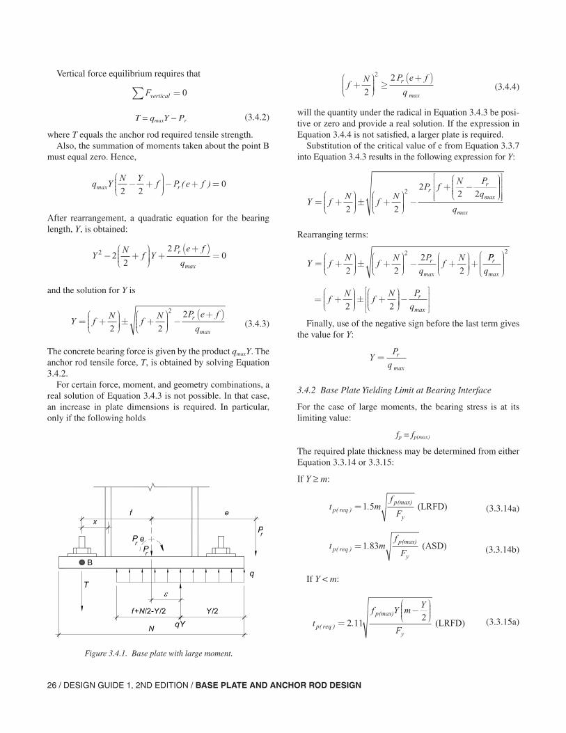
26 / DESIGN GUIDE 1, 2ND EDITION / BASE PLATE AND ANCHOR ROD DESIGN
Vertical force equilibrium requires that
T = qmaxY − Pr
where T equals the anchor rod required tensile strength.Also, the summation of moments taken about the point B
must equal zero. Hence,
After rearrangement, a quadratic equation for the bearing length, Y, is obtained:
and the solution for Y is
The concrete bearing force is given by the product qmaxY. The anchor rod tensile force, T, is obtained by solving Equation 3.4.2.
For certain force, moment, and geometry combinations, a real solution of Equation 3.4.3 is not possible. In that case, an increase in plate dimensions is required. In particular, only if the following holds
will the quantity under the radical in Equation 3.4.3 be posi-tive or zero and provide a real solution. If the expression in Equation 3.4.4 is not satisfied, a larger plate is required.
Substitution of the critical value of e from Equation 3.3.7 into Equation 3.4.3 results in the following expression for Y:
Rearranging terms:
Finally, use of the negative sign before the last term gives
the value for Y:
3.4.2 Base Plate Yielding Limit at Bearing Interface
For the case of large moments, the bearing stress is at its limiting value:
fp = fp(max)
The required plate thickness may be determined from either Equation 3.3.14 or 3.3.15:
If Y ≥ m:
If Y < m:
Figure 3.4.1. Base plate with large moment.
Fvertical∑ = 0
(3.4.2)
q YN Y
f P e frmax ( )2 2
0− +
− + =
YN
f YP e f
qr2 2
2
20− +
+
+( )=
max
Y fN
fN P e f
qr= +
± +
−
+( )2 2
22
max(3.4.3)
fN P e f
qr+
≥
+( )2
22
max(3.4.4)
Y fN
fN
P fN P
qrr
= +
± +
−
+ −
2 2
22 22
max
qmax
Y fN
fN P
qf
Nr= +
± +
− +
+2 2
2
2
2
max
PP
qr
max
2
= +
± +
−
f
Nf
N P
qr
2 2 max
YP
qr=
max
t mf
Fp reqp
y( )
(max).=1 5 (LRFD) (3.3.14a)
t mf
Fp reqp
y( )
(max).=1 83 (ASD) (3.3.14b)
tf Y m
Y
Fp req
p
y( )
(max)
.=−
2 112
(LRFD) (3.3.15a)
DESIGN GUIDE 1, 2ND EDITION / BASE PLATE AND ANCHOR ROD DESIGN / 27
Note: When n is larger than m, the thickness will be gov-erned by n. To determine the required thickness, substitute n for m in Equations 3.3.14 and 3.3.15.
3.4.3 Base Plate Yielding Limit at Tension Interface
The tension force Tu (LRFD), Ta (ASD) in the anchor rods will cause bending in the base plate. Cantilever action is conservatively assumed with the span length equal to the distance from the rod centerline to the center of the column flange, x. Alternately the bending lines could be assumed as shown in Figure 3.1.1. For a unit width of base plate, the re-quired bending strength of the base plate can be determined as
where
with
d = depth of wide flange column section (see Fig. 3.1.1)
tf = column flange thickness
The available strength per unit length for the plate is given in Equation 3.3.13. Setting that strength equal to the applied moment given by Equation 3.4.5 provides an expression for the required plate thickness:
3.4.4 General Design Procedure
1. Determine the axial load and moment.
2. Pick a trial base plate size, N × B.
3. Determine the equivalent eccentricity
e = Mr /Pr
and the critical eccentricity,
If e > ecrit, go to next step (design of the base plate with large moment); otherwise, refer to design of the base plate with small moment described in Section 3.3.
Check the inequality of Equation 3.4.4. If it is not satis-fied, choose larger plate dimensions.
4. Determine the equivalent bearing length, Y and tensile force in the anchor rod, Tu (LRFD), Ta (ASD).
5. Determine the required minimum base plate thickness tp(req) at bearing and tension interfaces. Choose the larger value.
6. Determine the anchor rod size.
3.5 Design for Shear
There are three principal ways of transferring shear from column base plates into concrete:
1. Friction between the base plate and the grout or concrete surface.
2. Bearing of the column and base plate, and/or shear lug, against a concrete surface.
3. Shear in the anchor rods.
3.5.1 Friction
In typical base plate situations, the compression force be-tween the base plate and the concrete will usually develop shear resistance sufficient to resist the lateral forces. The contribution of the shear should be based on the most un-favorable arrangement of factored compressive loads, Pu, that is consistent with the lateral force being evaluated, Vu. The shear strength can be calculated in accordance with ACI criteria,
φVn = φµPu ≤ 0.2fc′Ac
The friction coefficient µ is 0.55 for steel on grout, and 0.7 for steel on concrete.
3.5.2 Bearing
Shear forces can be transferred in bearing by the use of shear lugs or by embedding the column in the foundation. These methods are illustrated in Figure 3.5.1.
tf Y m
Y
Fp req
p
y( )
(max)
.=−
2 582
(ASD) (3.3.15b)
MT x
Bplu= (LRFD) (3.4.5a)
MT x
Bpla= (ASD) (3.4.5b)
x fd t f= − +2 2
(3.4.6)
tT x
BFp requ
y( ) .= 2 11 (LRFD) (3.4.7a)
tT x
BFp reqa
y( ) .= 2 58 (ASD)
(3.4.7b)
eN P
qcritr= −
2 2 max
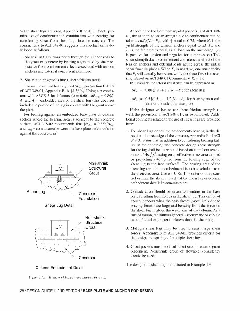
28 / DESIGN GUIDE 1, 2ND EDITION / BASE PLATE AND ANCHOR ROD DESIGN
When shear lugs are used, Appendix B of ACI 349-01 per-mits use of confinement in combination with bearing for transferring shear from shear lugs into the concrete. The commentary to ACI 349-01 suggests this mechanism is de-veloped as follows:
1. Shear is initially transferred through the anchor rods to the grout or concrete by bearing augmented by shear re-sistance from confinement effects associated with tension anchors and external concurrent axial load.
2. Shear then progresses into a shear-friction mode.
The recommended bearing limit φPubrg per Section B.4.5.2 of ACI 349-01, Appendix B, is φ1.3fc′A1. Using a φ consis-tent with ASCE 7 load factors (φ = 0.60), φPubrg ≈ 0.80fc′ A1 and A1 = embedded area of the shear lug (this does not include the portion of the lug in contact with the grout above the pier).
For bearing against an embedded base plate or column section where the bearing area is adjacent to the concrete surface, ACI 318-02 recommends that φPubrg = 0.55fc′Abrg, and Abrg = contact area between the base plate and/or column against the concrete, in2.
According to the Commentary of Appendix B of ACI 349-01, the anchorage shear strength due to confinement can be taken as φKc (Ny − Pa), with φ equal to 0.75, where Ny is the yield strength of the tension anchors equal to nAseFy, and Pa is the factored external axial load on the anchorage. (Pa
is positive for tension and negative for compression.) This shear strength due to confinement considers the effect of the tension anchors and external loads acting across the initial shear fracture planes. When Pa is negative, one must verify that Pa will actually be present while the shear force is occur-ring. Based on ACI 349-01 Commentary, Kc = 1.6.
In summary, the lateral resistance can be expressed as
φPn = 0.80 fc′ A + 1.2(Ny − Pa) for shear lugs
φPn = 0.55fc′ Abrg + 1.2(Ny − Pa) for bearing on a col-umn or the side of a base plate
If the designer wishes to use shear-friction strength as well, the provisions of ACI 349-01 can be followed. Addi-tional comments related to the use of shear lugs are provided here:
1. For shear lugs or column embedments bearing in the di-rection of a free edge of the concrete, Appendix B of ACI 349-01 states that, in addition to considering bearing fail-ure in the concrete, “the concrete design shear strength for the lug shall be determined based on a uniform tensile stress of 4φ ′fc acting on an effective stress area defined by projecting a 45° plane from the bearing edge of the shear lug to the free surface.” The bearing area of the shear lug (or column embedment) is to be excluded from the projected area. Use φ = 0.75. This criterion may con-trol or limit the shear capacity of the shear lug or column embedment details in concrete piers.
2. Consideration should be given to bending in the base plate resulting from forces in the shear lug. This can be of special concern when the base shears (most likely due to bracing forces) are large and bending from the force on the shear lug is about the weak axis of the column. As a rule of thumb, the authors generally require the base plate to be of equal or greater thickness than the shear lug.
3. Multiple shear lugs may be used to resist large shear forces. Appendix B of ACI 349-01 provides criteria for the design and spacing of multiple shear lugs.
4. Grout pockets must be of sufficient size for ease of grout placement. Nonshrink grout of flowable consistency should be used.
The design of a shear lug is illustrated in Example 4.9.
Figure 3.5.1. Transfer of base shears through bearing.
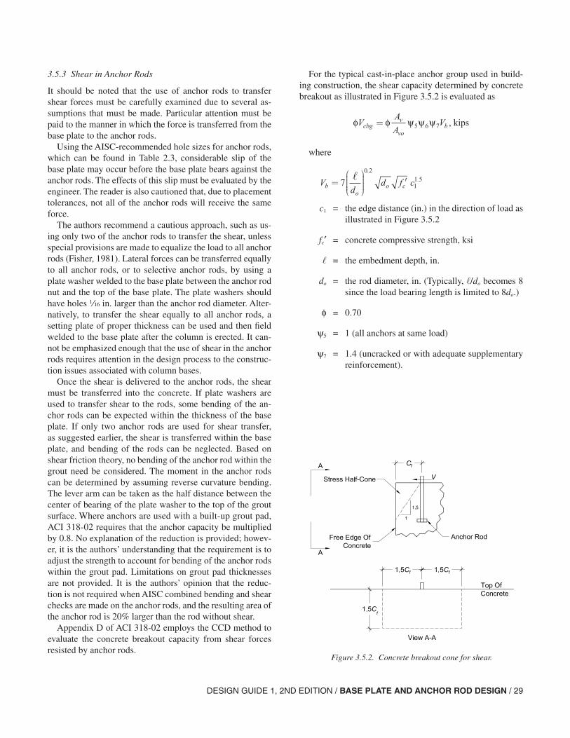
DESIGN GUIDE 1, 2ND EDITION / BASE PLATE AND ANCHOR ROD DESIGN / 29
3.5.3 Shear in Anchor Rods
It should be noted that the use of anchor rods to transfer shear forces must be carefully examined due to several as-sumptions that must be made. Particular attention must be paid to the manner in which the force is transferred from the base plate to the anchor rods.
Using the AISC-recommended hole sizes for anchor rods, which can be found in Table 2.3, considerable slip of the base plate may occur before the base plate bears against the anchor rods. The effects of this slip must be evaluated by the engineer. The reader is also cautioned that, due to placement tolerances, not all of the anchor rods will receive the same force.
The authors recommend a cautious approach, such as us-ing only two of the anchor rods to transfer the shear, unless special provisions are made to equalize the load to all anchor rods (Fisher, 1981). Lateral forces can be transferred equally to all anchor rods, or to selective anchor rods, by using a plate washer welded to the base plate between the anchor rod nut and the top of the base plate. The plate washers should have holes z in. larger than the anchor rod diameter. Alter-natively, to transfer the shear equally to all anchor rods, a setting plate of proper thickness can be used and then field welded to the base plate after the column is erected. It can-not be emphasized enough that the use of shear in the anchor rods requires attention in the design process to the construc-tion issues associated with column bases.
Once the shear is delivered to the anchor rods, the shear must be transferred into the concrete. If plate washers are used to transfer shear to the rods, some bending of the an-chor rods can be expected within the thickness of the base plate. If only two anchor rods are used for shear transfer, as suggested earlier, the shear is transferred within the base plate, and bending of the rods can be neglected. Based on shear friction theory, no bending of the anchor rod within the grout need be considered. The moment in the anchor rods can be determined by assuming reverse curvature bending. The lever arm can be taken as the half distance between the center of bearing of the plate washer to the top of the grout surface. Where anchors are used with a built-up grout pad, ACI 318-02 requires that the anchor capacity be multiplied by 0.8. No explanation of the reduction is provided; howev-er, it is the authors’ understanding that the requirement is to adjust the strength to account for bending of the anchor rods within the grout pad. Limitations on grout pad thicknesses are not provided. It is the authors’ opinion that the reduc-tion is not required when AISC combined bending and shear checks are made on the anchor rods, and the resulting area of the anchor rod is 20% larger than the rod without shear.
Appendix D of ACI 318-02 employs the CCD method to evaluate the concrete breakout capacity from shear forces resisted by anchor rods.
For the typical cast-in-place anchor group used in build-ing construction, the shear capacity determined by concrete breakout as illustrated in Figure 3.5.2 is evaluated as
where
c1 = the edge distance (in.) in the direction of load as illustrated in Figure 3.5.2
fc′ = concrete compressive strength, ksi
= the embedment depth, in.
do = the rod diameter, in. (Typically, /do becomes 8 since the load bearing length is limited to 8do.)
φ = 0.70
ψ5 = 1 (all anchors at same load)
ψ7 = 1.4 (uncracked or with adequate supplementary reinforcement).
Figure 3.5.2. Concrete breakout cone for shear.
φ φ ψ ψ ψVA
AVcbg
v
vob= 5 6 7 , kips
Vd
d f cbo
o c=
′70 2
11 5
..
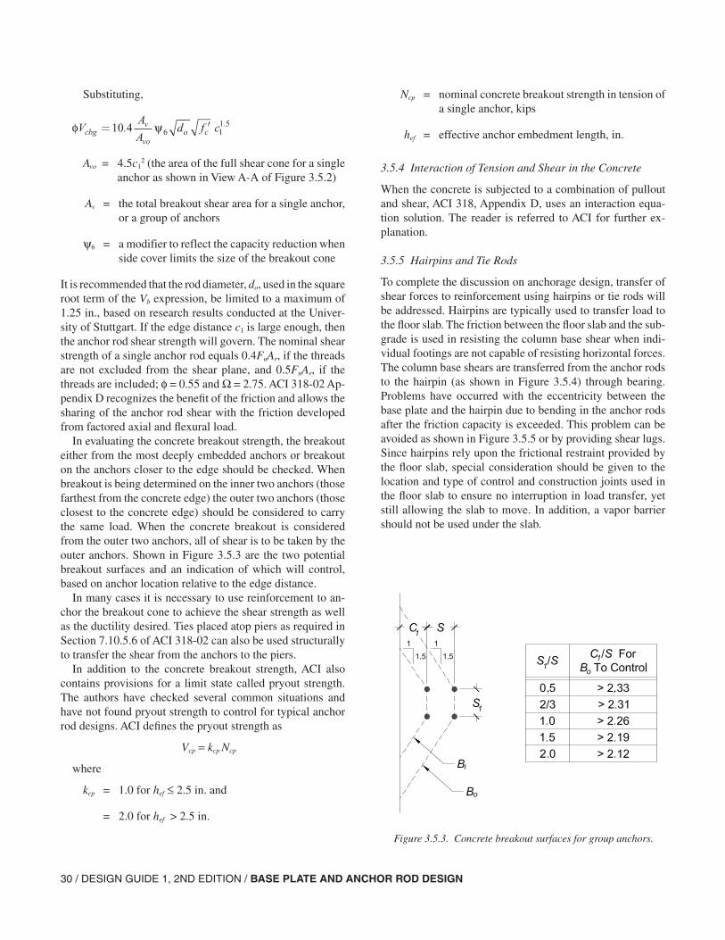
30 / DESIGN GUIDE 1, 2ND EDITION / BASE PLATE AND ANCHOR ROD DESIGN
Substituting,
Avo = 4.5c12 (the area of the full shear cone for a single
anchor as shown in View A-A of Figure 3.5.2)
Av = the total breakout shear area for a single anchor, or a group of anchors
ψ6 = a modifier to reflect the capacity reduction when side cover limits the size of the breakout cone
It is recommended that the rod diameter, do, used in the square root term of the Vb expression, be limited to a maximum of 1.25 in., based on research results conducted at the Univer-sity of Stuttgart. If the edge distance c1 is large enough, then the anchor rod shear strength will govern. The nominal shear strength of a single anchor rod equals 0.4FuAr, if the threads are not excluded from the shear plane, and 0.5FuAr, if the threads are included; φ = 0.55 and Ω = 2.75. ACI 318-02 Ap-pendix D recognizes the benefit of the friction and allows the sharing of the anchor rod shear with the friction developed from factored axial and flexural load.
In evaluating the concrete breakout strength, the breakout either from the most deeply embedded anchors or breakout on the anchors closer to the edge should be checked. When breakout is being determined on the inner two anchors (those farthest from the concrete edge) the outer two anchors (those closest to the concrete edge) should be considered to carry the same load. When the concrete breakout is considered from the outer two anchors, all of shear is to be taken by the outer anchors. Shown in Figure 3.5.3 are the two potential breakout surfaces and an indication of which will control, based on anchor location relative to the edge distance.
In many cases it is necessary to use reinforcement to an-chor the breakout cone to achieve the shear strength as well as the ductility desired. Ties placed atop piers as required in Section 7.10.5.6 of ACI 318-02 can also be used structurally to transfer the shear from the anchors to the piers.
In addition to the concrete breakout strength, ACI also contains provisions for a limit state called pryout strength. The authors have checked several common situations and have not found pryout strength to control for typical anchor rod designs. ACI defines the pryout strength as
Vcp = kcp Ncp
where
kcp = 1.0 for hef ≤ 2.5 in. and
= 2.0 for hef > 2.5 in.
Ncp = nominal concrete breakout strength in tension of a single anchor, kips
hef = effective anchor embedment length, in.
3.5.4 Interaction of Tension and Shear in the Concrete
When the concrete is subjected to a combination of pullout and shear, ACI 318, Appendix D, uses an interaction equa-tion solution. The reader is referred to ACI for further ex-planation.
3.5.5 Hairpins and Tie Rods
To complete the discussion on anchorage design, transfer of shear forces to reinforcement using hairpins or tie rods will be addressed. Hairpins are typically used to transfer load to the floor slab. The friction between the floor slab and the sub-grade is used in resisting the column base shear when indi-vidual footings are not capable of resisting horizontal forces. The column base shears are transferred from the anchor rods to the hairpin (as shown in Figure 3.5.4) through bearing. Problems have occurred with the eccentricity between the base plate and the hairpin due to bending in the anchor rods after the friction capacity is exceeded. This problem can be avoided as shown in Figure 3.5.5 or by providing shear lugs. Since hairpins rely upon the frictional restraint provided by the floor slab, special consideration should be given to the location and type of control and construction joints used in the floor slab to ensure no interruption in load transfer, yet still allowing the slab to move. In addition, a vapor barrier should not be used under the slab.
φ ψVA
Ad f ccbg
v
voo c= ′10 4 6 1
1 5. .
Figure 3.5.3. Concrete breakout surfaces for group anchors.
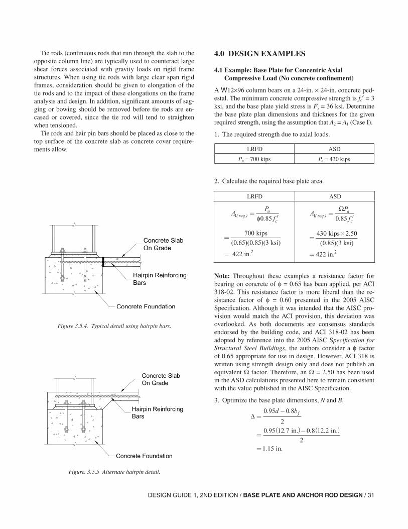
DESIGN GUIDE 1, 2ND EDITION / BASE PLATE AND ANCHOR ROD DESIGN / 31
LRFD ASD
4.0 DESIGN EXAMPLES
4.1 Example: Base Plate for Concentric Axial Compressive Load (No concrete confinement)
A W12×96 column bears on a 24-in. × 24-in. concrete ped-estal. The minimum concrete compressive strength is fc′ = 3 ksi, and the base plate yield stress is Fy = 36 ksi. Determine the base plate plan dimensions and thickness for the given required strength, using the assumption that A2 = A1 (Case I).
1. The required strength due to axial loads.
2. Calculate the required base plate area.
Note: Throughout these examples a resistance factor for bearing on concrete of φ = 0.65 has been applied, per ACI 318-02. This resistance factor is more liberal than the re-sistance factor of φ = 0.60 presented in the 2005 AISC Specification. Although it was intended that the AISC pro-vision would match the ACI provision, this deviation was overlooked. As both documents are consensus standards endorsed by the building code, and ACI 318-02 has been adopted by reference into the 2005 AISC Specification for Structural Steel Buildings, the authors consider a φ factor of 0.65 appropriate for use in design. However, ACI 318 is written using strength design only and does not publish an equivalent Ω factor. Therefore, an Ω = 2.50 has been used in the ASD calculations presented here to remain consistent with the value published in the AISC Specification.
3. Optimize the base plate dimensions, N and B.
Tie rods (continuous rods that run through the slab to the opposite column line) are typically used to counteract large shear forces associated with gravity loads on rigid frame structures. When using tie rods with large clear span rigid frames, consideration should be given to elongation of the tie rods and to the impact of these elongations on the frame analysis and design. In addition, significant amounts of sag-ging or bowing should be removed before tie rods are en-cased or covered, since the tie rod will tend to straighten when tensioned.
Tie rods and hair pin bars should be placed as close to the top surface of the concrete slab as concrete cover require-ments allow.
Figure. 3.5.5 Alternate hairpin detail.
Figure 3.5.4. Typical detail using hairpin bars.
LRFD ASD
Pu = 700 kips Pa = 430 kips
AP
frequ
c1 0 85( ) .
=′φ
=
=
700
0 65 0 852
kips
3 ksi)
422 in.
( . )( . )(
AP
freqa
c1 0 85( ) .
=′
Ω
=×
=
430 2 50
0 852
kips
3 ksi)
422 in.
.
( . )(
∆ =−
=( )− ( )
=
≈
0 95 0 8
20 95 12 7 0 8 12 2
21 15
1
. .
. . . .
.
(
d b
N A
f
in. in.
in.
rreq )
.
.
+
≈ +≈
∆
422 1 15
21 7
2 in. in.
in.
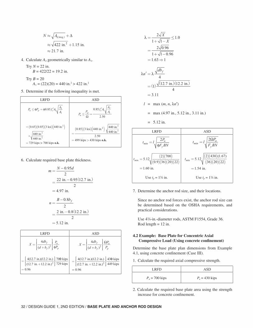
32 / DESIGN GUIDE 1, 2ND EDITION / BASE PLATE AND ANCHOR ROD DESIGN
4. Calculate A2 geometrically similar to A1.
Try N = 22 in.B = 422/22 = 19.2 in.
Try B = 20A1 = (22)(20) = 440 in.2 > 422 in.2
5. Determine if the following inequality is met.
6. Calculate required base plate thickness.
∆ =−
=( )− ( )
=
≈
0 95 0 8
20 95 12 7 0 8 12 2
21 15
1
. .
. . . .
.
(
d b
N A
f
in. in.
in.
rreq )
.
.
+
≈ +≈
∆
422 1 15
21 7
2 in. in.
in.
LRFD ASD
P P f AA
Au p c≤ = ′φ φ0 85 12
1
.
=( )( )( )( )
×
=
0 65 0 85
729
. . 3 ksi 440 in.
440 in.
440 in. kips
2
2
2
>> 700 kips o.k.
PP
f AA
Aa
pc
≤ =
′
Ω
0 85
2 50
12
1
.
.
=( )( )( )
= >
0 85
2 50499 430
.
.
3 ksi 440 in. 440 in.
440 in.
kips
22
2
kips o.k.
mN d
=−
=− ( )
=
0 95
222 0 95 12 7
24 97
.
. .
.
in. in.
in.
nB bf=−
=− ( )
=
0 8
22 0 8 12 2
25 12
.
. .
.
in. in.
in.
LRFD ASD
Xdb
d b
P
Pf
f
u
p
=+
42( ) φ
=+
4 12 7 12 2
12 7 12 2
702
( . )( . )
( . . )
in. in.
in. in.
00
0 96
kips
729 kips
= .
Xdb
d b
P
Pf
f
a
p
=+
42( )
Ω
=+
4 12 7 12 2
12 7 12 2
432
( . )( . )
( . . )
in. in.
in. in.
00
0 96
kips
449 kips
= .
l = max (m, n, λn′)
= max (4.97 in., 5.12 in., 3.11 in.)
= 5.12 in.
7. Determine the anchor rod size, and their locations.
Since no anchor rod forces exist, the anchor rod size can be determined based on the OSHA requirements, and practical considerations.
Use 4w-in.-diameter rods, ASTM F1554, Grade 36. Rod length = 12 in.
4.2 Example: Base Plate for Concentric Axial Compressive Load (Using concrete confinement)
Determine the base plate plan dimensions from Example 4.1, using concrete confinement (Case III).
1. Calculate the required axial compressive strength.
2. Calculate the required base plate area using the strength increase for concrete confinement.
λ =+ −
≤
=+ −
= ⇒
2
1 11 0
2 0 96
1 1 0 961 63 1
X
X.
.
..
LRFD ASD
Use tp = 1w in. Use tp = 1w in.
λ λ′ =
=( )( )( )
=
ndbf
4
112 7 12 2
43 11
. .
.
in. in.
t lP
F BNu
ymin =
2
φ
tmin ..
.
=( )( )
( )( )( )( )=
5 122 700
0 9 36 20 22
1 60 in.
t lP
F BNa
ymin =
2Ω
tmin ..
.
=( )( )( )( )( )
=
5 122 430 1 67
36 20 22
1 54
( )
in.
LRFD ASD
Pu = 700 kips Pa = 430 kips
DESIGN GUIDE 1, 2ND EDITION / BASE PLATE AND ANCHOR ROD DESIGN / 33
7. Calculate required base plate thickness.
3. Optimize the base plate dimensions, N and B.
Try N = 16 in.B = 211/16 = 13.2
Try B = 14 in.
4. Calculate A2 geometrically similar to A1.
Based on the 24-in. pier,
N2 = 24 in.
Ratio B/N = 14/16 = 0.88
B2 = (0.88)(24) = 21.12 in.
A2 = (24)(21.12) = 507
507 ≤ 4A1 = (4)(211) = 844 in.2
Case III applies.
5. Use trial and error solution.
Try N = 20 in. B = 18 in.
A1 = (20)(18) = 360 in.2
N2 = 24 in.
Ratio B/N = 18/20 = 0.9
B2 = (0.9)(24) = 21.6 in.
A2 = (24)(21.6) = 518 in.2
LRFD ASD
AP
frequ
c1 2 0 85( ) .
=′φ
=
=
700
2 0 65 0 85
211
kips
3 ksi)
in.2( )( . )( . )(
AP
freqa
c1 2 0 85( ) .
=× ′
Ω
=×
=
430 2 50
2 0 85
211 2
kips
3 ksi)
in.
.
( )( . )(
∆ =−
=−
=
≈
0 95 0 8
20 95 12 7 0 8 12 2
21 15
1
. .
. . . .
.
(
d b
N A
f
( ) ( ) in. in.
in.
rreq )
.
.
+
≈ +≈
∆
211 in. in.
in.
2 1 15
15 7
LRFD ASD
6. Determine if Pu ≤ φcPp, if not revise N and B, and retry until criterion is satisfied.
Pu ≤ φ Pp
700 kips ≤ 716 kips o.k.
Use N = 20 in., B = 18 in.
6. Determine if Pa ≤ Pp /Ω, if not revise N and B, and retry until criterion is satisfied.
430 kips ≤ 400 kips o.k.
Use N = 20 in., B = 18 in.
φ φP f AA
Ap c= ′0 85 12
1
.
=
× =
( . )( . )(0 65 0 85
716
3 ksi)(360 in. )
518 in.
360 in. kips
2
2
2
Pf A
A
Apc
Ω Ω=
′0 85 12
1
.
=
=
( . )(
.
0 85
2 50440
3 ksi)(360 in. )518 in.
360 in.
kips
22
2
PP
ap≤
Ω
mN d
=−
=−
0 95
220 0 95 12 7
2
.
. ( . in. in.)
= 3.97 in.
nB bf=−
=−
0 8
20 8 12 2
2
.
. ( .18.5 in. in.)
= 4.37 in.
LRFD ASD
Xdb
d b
P
Pf
f
u
p
=+
42( ) φ
Xdb
d b
P
Pf
f
a
p
=+
42( )
Ω
=+
4 12 7 12 2
12 7 12 2
702
( . )( . )
( . . )
in. in.
in. in.
00
716
0 98
kips
kips
= .
=+
4 12 7 12 2
12 7 12 2
702
( . )( . )
( . . )
in. in.
in. in.
00
716
0 98
kips
kips
= .
λ =+ −
=+ −
= ⇒
2
1 1
2 0 98
1 1 0 981 73 1
X
X
.
..
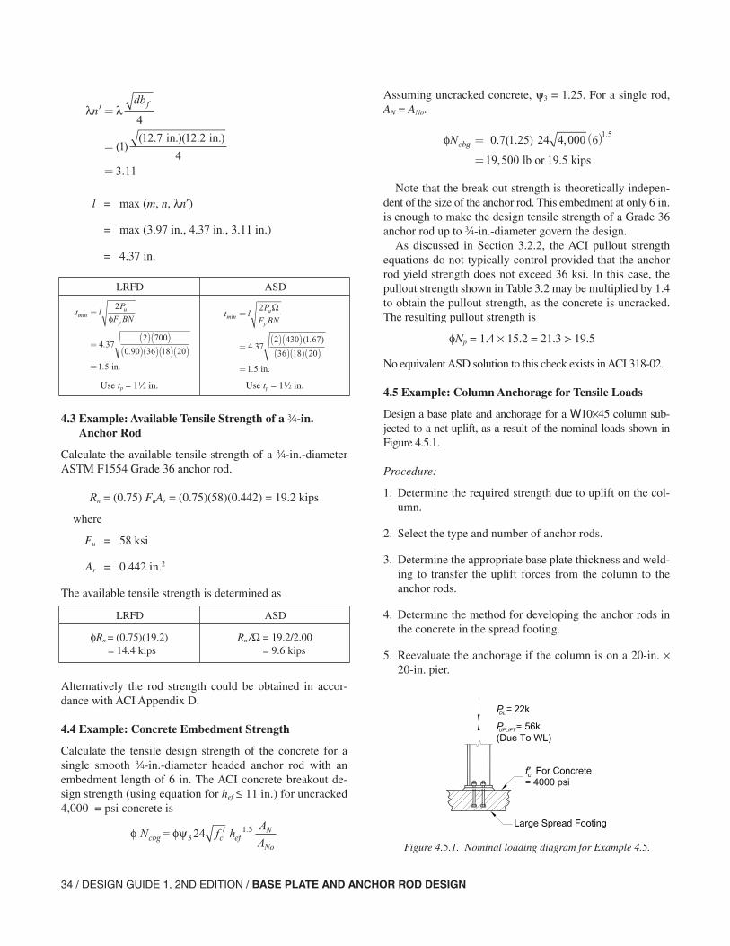
34 / DESIGN GUIDE 1, 2ND EDITION / BASE PLATE AND ANCHOR ROD DESIGN
l = max (m, n, λn′)
= max (3.97 in., 4.37 in., 3.11 in.)
= 4.37 in.
4.3 Example: Available Tensile Strength of a w-in. Anchor Rod
Calculate the available tensile strength of a w-in.-diameter ASTM F1554 Grade 36 anchor rod.
Rn = (0.75) FuAr = (0.75)(58)(0.442) = 19.2 kips
where
Fu = 58 ksi
Ar = 0.442 in.2
The available tensile strength is determined as
Alternatively the rod strength could be obtained in accor-dance with ACI Appendix D.
4.4 Example: Concrete Embedment Strength
Calculate the tensile design strength of the concrete for a single smooth w-in.-diameter headed anchor rod with an embedment length of 6 in. The ACI concrete breakout de-sign strength (using equation for hef ≤ 11 in.) for uncracked 4,000 = psi concrete is
λ λ′ =
=
=
ndbf
4
112 7 12 2
43 11
( )( . )( . )
.
in. in.
LRFD ASD
Use tp = 12 in. Use tp = 12 in.
t lP
F BNu
ymin
..
.
=
=( )( )
( )( )( )( )=
2
4 372 700
0 90 36 18 20
1 5
φ
in.
t lP
F BNa
ymin
..
.
=
=( )( )( )( )( )
=
2
4 372 430 1 67
36 18 20
1 5
Ω
( )
in.
LRFD ASD
φRn = (0.75)(19.2) = 14.4 kips
Rn /Ω = 19.2/2.00 = 9.6 kips
φ φψ = 3N f hA
Acbg c efN
No
24 1 5′ .
Assuming uncracked concrete, ψ3 = 1.25. For a single rod, AN = ANo.
Note that the break out strength is theoretically indepen-dent of the size of the anchor rod. This embedment at only 6 in. is enough to make the design tensile strength of a Grade 36 anchor rod up to w-in.-diameter govern the design.
As discussed in Section 3.2.2, the ACI pullout strength equations do not typically control provided that the anchor rod yield strength does not exceed 36 ksi. In this case, the pullout strength shown in Table 3.2 may be multiplied by 1.4 to obtain the pullout strength, as the concrete is uncracked. The resulting pullout strength is
φNp = 1.4 × 15.2 = 21.3 > 19.5
No equivalent ASD solution to this check exists in ACI 318-02.
4.5 Example: Column Anchorage for Tensile Loads
Design a base plate and anchorage for a W10×45 column sub-jected to a net uplift, as a result of the nominal loads shown in Figure 4.5.1.
Procedure:
1. Determine the required strength due to uplift on the col-umn.
2. Select the type and number of anchor rods.
3. Determine the appropriate base plate thickness and weld-ing to transfer the uplift forces from the column to the anchor rods.
4. Determine the method for developing the anchor rods in the concrete in the spread footing.
5. Reevaluate the anchorage if the column is on a 20-in. × 20-in. pier.
6
lb or kips
φNcbg = ( )
=
0 7 1 25 24 4 000
19 500 19 5
1 5. ( . ) ,
, .
.
Figure 4.5.1. Nominal loading diagram for Example 4.5.
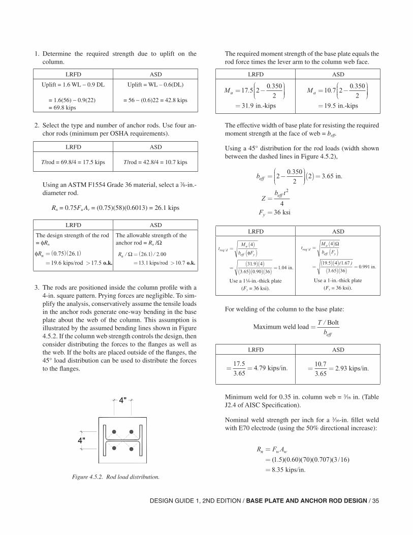
DESIGN GUIDE 1, 2ND EDITION / BASE PLATE AND ANCHOR ROD DESIGN / 35
1. Determine the required strength due to uplift on the column.
2. Select the type and number of anchor rods. Use four an-chor rods (minimum per OSHA requirements).
Using an ASTM F1554 Grade 36 material, select a d-in.-diameter rod.
Rn = 0.75Fu Ar = (0.75)(58)(0.6013) = 26.1 kips
3. The rods are positioned inside the column profile with a 4-in. square pattern. Prying forces are negligible. To sim-plify the analysis, conservatively assume the tensile loads in the anchor rods generate one-way bending in the base plate about the web of the column. This assumption is illustrated by the assumed bending lines shown in Figure 4.5.2. If the column web strength controls the design, then consider distributing the forces to the flanges as well as the web. If the bolts are placed outside of the flanges, the 45° load distribution can be used to distribute the forces to the flanges.
LRFD ASD
Uplift = 1.6 WL − 0.9 DL
= 1.6(56) − 0.9(22) = 69.8 kips
Uplift = WL – 0.6(DL)
= 56 − (0.6)22 = 42.8 kips
LRFD ASD
T/rod = 69.8/4 = 17.5 kips T/rod = 42.8/4 = 10.7 kips
LRFD ASD
The design strength of the rod = φRn
The allowable strength of the anchor rod = Rn /Ω
φRn =( )( )
= >
0 75 26 1
19 6 17 5
. .
. . kips/rod o.k.
Rn / . / .
. .
Ω=( )
= >
26 1 2 00
13 1 10 7 kips/rod o.k.
Figure 4.5.2. Rod load distribution.
The required moment strength of the base plate equals the rod force times the lever arm to the column web face.
The effective width of base plate for resisting the required moment strength at the face of web = beff.
Using a 45° distribution for the rod loads (width shown between the dashed lines in Figure 4.5.2),
For welding of the column to the base plate:
Minimum weld for 0.35 in. column web = x in. (Table J2.4 of AISC Specification).
Nominal weld strength per inch for a x-in. fillet weld with E70 electrode (using the 50% directional increase):
LRFD ASD
Mu = −
=
17 5 20 350
2
31 9
..
. in.-kips
Ma = −
=
10 7 20 350
2
19 5
..
. in.-kips
b
Zb t
F
eff
eff
y
= −
( )=
=
=
20 350
22 3 65
436
2
.. in.
ksi
LRFD ASD
Use a 14-in.-thick plate (Fy = 36 ksi).
Use a 1-in.-thick plate (Fy = 36 ksi).
tM
b Freq d
u
eff y’
.
. ..
=( )( )
=( )( )
( )( )( )=
4
31 9 4
3 65 0 90 361 04
φ
in.
tM
b Freq d
a
eff y’
. ( . )
..
=( )( )
=( )( )( )( )
=
4
19 5 4 1 67
3 65 360 991
Ω
in.
Maximum weld loadBolt
=T
beff
/
LRFD ASD
= =17 5
3 654 79
.
.. . kips/in = =
10 7
3 652 93
.
.. . kips/in
R F An w w=
==
( . )( . )( )( . )( / )
.
1 5 0 60 70 0 707 3 16
8 35 kips/in.
36 / DESIGN GUIDE 1, 2ND EDITION / BASE PLATE AND ANCHOR ROD DESIGN
Check web:
Web stress = Force per in./Area of web per in.
4. As noted earlier, this column is anchored in the middle of a large spread footing. Therefore, there are no edge constraints on the concrete tensile cones and there is no concern regarding edge distance to prevent lateral break-out of the concrete.
Try using a 32-in. hook on the embedded end of the anchor rod to develop the rod. As mentioned earlier in this Guide, the use of hooked anchor rods is generally not recommended. Their use here is to demonstrate their limited pull out strength.
Note that no equivalent ASD solution exists for concrete bearing capacity.
Based on uniform bearing on the hook, the hook bearing capacity per ACI 318-02 Appendix D
= φ (0.9)(fc′)(do)(eh)(ψ4)
where
φ = 0.70
f ′c = concrete compressive strength
do = hook diameter
eh = hook projection
ψ4 = cracking factor (1.0 for cracked, 1.4 for un-cracked concrete)
Hook bearing capacity = 0.70(0.9)(4,000) × (7/8)(3.5 − 0.875)(1.4) = 8,100 lb = 8.10 kips < 17.50 kips n.g.
LRFD ASD
LRFD ASD
φRn = (0.75)(8.35) = 6.26 kips/in.
4.79 < 6.26
x-in. fillet weld on each side of the column web is o.k.
Rn /Ω = (8.35)/2.0 = 4.16 kips/in.
2.93 < 4.16
x-in. fillet weld on each side of the column web is o.k.
Web stress 2 4.79 kips/in.
in. ksi in web
=×
=<
0 3527 4
0 9
..
. Fy oof column, o.k.
Web stress2 2.93 kips/in.
in. ksi in web
=×
=<
0 3516 7
1 67
..
/ .Fy of column, o.k.
Thus, a 32-in. hook is not capable of developing the re-quired tensile force in the rod.
Therefore, use a heavy hex nut to develop the anchor rod.
The pullout strength of a d-in.-diameter anchor rod from Table 3.2 is 20.5 kips, which is greater than the required strength per anchor rod.
The required embedment depth to achieve a concrete breakout strength, φNcbg, that exceeds the required uplift of 69.8 kips can be determined by trial and error. The final trial with an embedment length of 13 in. is shown below.
Per ACI 318-02, Appendix D, the concrete breakout strength:
and
where
φ = 0.70
ψ3 = 1.25 considering the concrete to be uncracked
hef = 13 in.
AN = concrete breakout cone area for group
= [3(13) + (4)(3)(13) + 4] = 1,849 in.2
ANo = concrete breakout cone area for single anchor = 9(13)2 = 1,521 in.2
= 77,400 lb = 77.4 kips > 69.8 kips o.k.
With the d-in.-diameter anchors, a 13-in. embedment is adequate to achieve the anchor capacity considering the full breakout capacity.
5. If the anchors were installed in a 20-in. square pier, the concrete breakout strength would be limited by the pier cross section. With an 8-in. maximum edge distance, the effective hef need be only 8/1.5 = 5.33 in. to have the breakout cone area equal the pier cross sectional area.
φ φψ = for in.3N f hA
Ahcbg c ef
N
Noef24 111 5′ ≤.
φ φψ = for in.3N f hA
Ahcbg c ef
N
Noef16 115 3′ >/
φ = Ncbg 0 70 1 25 16 4 000 131850
15205 3. ( . )( ) , ( ) /
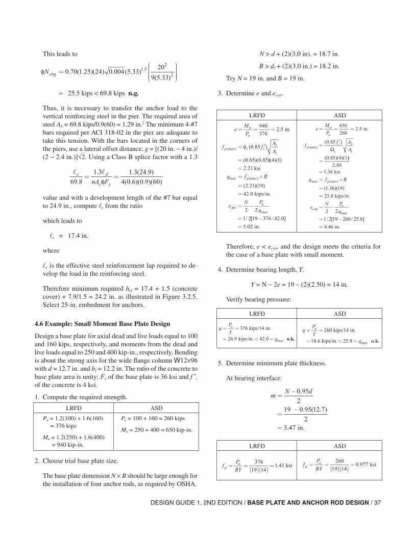
DESIGN GUIDE 1, 2ND EDITION / BASE PLATE AND ANCHOR ROD DESIGN / 37
This leads to
= 25.5 kips < 69.8 kips n.g.
Thus, it is necessary to transfer the anchor load to the vertical reinforcing steel in the pier. The required area of steel AS = 69.8 kips/0.9(60) = 1.29 in.2 The minimum 4-#7 bars required per ACI 318-02 in the pier are adequate to take this tension. With the bars located in the corners of the piers, use a lateral offset distance, g = [(20 in. − 4 in.)/ (2 − 2.4 in.)]√2. Using a Class B splice factor with a 1.3
value and with a development length of the #7 bar equal to 24.9 in., compute e from the ratio
which leads to
e = 17.4 in.
where
e is the effective steel reinforcement lap required to de-velop the load in the reinforcing steel.
Therefore minimum required hef = 17.4 + 1.5 (concrete cover) + 7.9/1.5 = 24.2 in. as illustrated in Figure 3.2.5. Select 25-in. embedment for anchors.
4.6 Example: Small Moment Base Plate Design
Design a base plate for axial dead and live loads equal to 100 and 160 kips, respectively, and moments from the dead and live loads equal to 250 and 400 kip-in., respectively. Bending is about the strong axis for the wide flange column W12×96 with d = 12.7 in. and bf = 12.2 in. The ratio of the concrete to base plate area is unity; Fy of the base plate is 36 ksi and f ′c of the concrete is 4 ksi.
1. Compute the required strength.
2. Choose trial base plate size.
The base plate dimension N × B should be large enough for the installation of four anchor rods, as required by OSHA.
φNcbg =
0 70 1 25 24 0 004 5 3320
9 5 331 5
2
2. ( . )( ) . ( . )
( . ).
e d
s ynA F69 8
1 3 1 3 24 9
4 0 6 0 9 60.
. . ( . )
( . )( . )( )= =
φ
LRFD ASD
Pu = 1.2(100) + 1.6(160) = 376 kips
Mu = 1.2(250) + 1.6(400) = 940 kip-in.
Pa = 100 + 160 = 260 kips
Ma = 250 + 400 = 650 kip-in.
N > d + (2)(3.0 in). = 18.7 in.
B > df + (2)(3.0 in.) = 18.2 in.
Try N = 19 in. and B = 19 in.
3. Determine e and ecrit.
Therefore, e < ecrit, and the design meets the criteria for the case of a base plate with small moment.
4. Determine bearing length, Y.
Y = N − 2e = 19 – (2)(2.50) = 14 in.
Verify bearing pressure:
5. Determine minimum plate thickness.
At bearing interface:
LRFD ASD
eM
P
f fA
A
u
u
p c c
= = =
= ′
=
940
3762 5
0 85
0 65 0 85
2
1
in..
( . )
( . )( .
( )max φ
))( )( )
.
( . )( )
.
( )
4 1
2 21
2 21 19
42 0
== ×
==
ksi
kips/in.
q f B
e
p
c
max max
rrituN P
q= −
= −=
2 2
1 2 19 376 42 0
5 02
max
/ [ / . ]
. in.
eM
P
ff A
A
a
a
pc
c
= = =
=′
=
650
260 in.
(0.85)(4)(1
2 5
0 85 2
1
.
( . )(max) Ω
))
2.50 ksi
kips/in.
== ×
==
1 36
1 36 19
25 8
.
( . )( )
.
( )q f B
e
p
cri
max max
ttaN P
q= −
= −=
2 2
1 2 19 260 25 8
4 46
max
/ [ / . ]
. in.
LRFD ASD
qP
Yq
u= =
= < =
376 14
26 9 42 0
kips/ in.
kips/in. . . max o.k.
qP
Yq
a= =
= < =
260 14
18 6 5 8
kips/ in.
kips/in. 2 . . max o.k.
mN d
=−
=−
=
0 95
219 0 95 12 7
23 47
.
. ( .
.
)
in.
LRFD ASD
fP
BYpu= =
( )( )=
376
19 141 41. ksi f
P
BYpa= =( )( )
=260
19 140 977. ksi
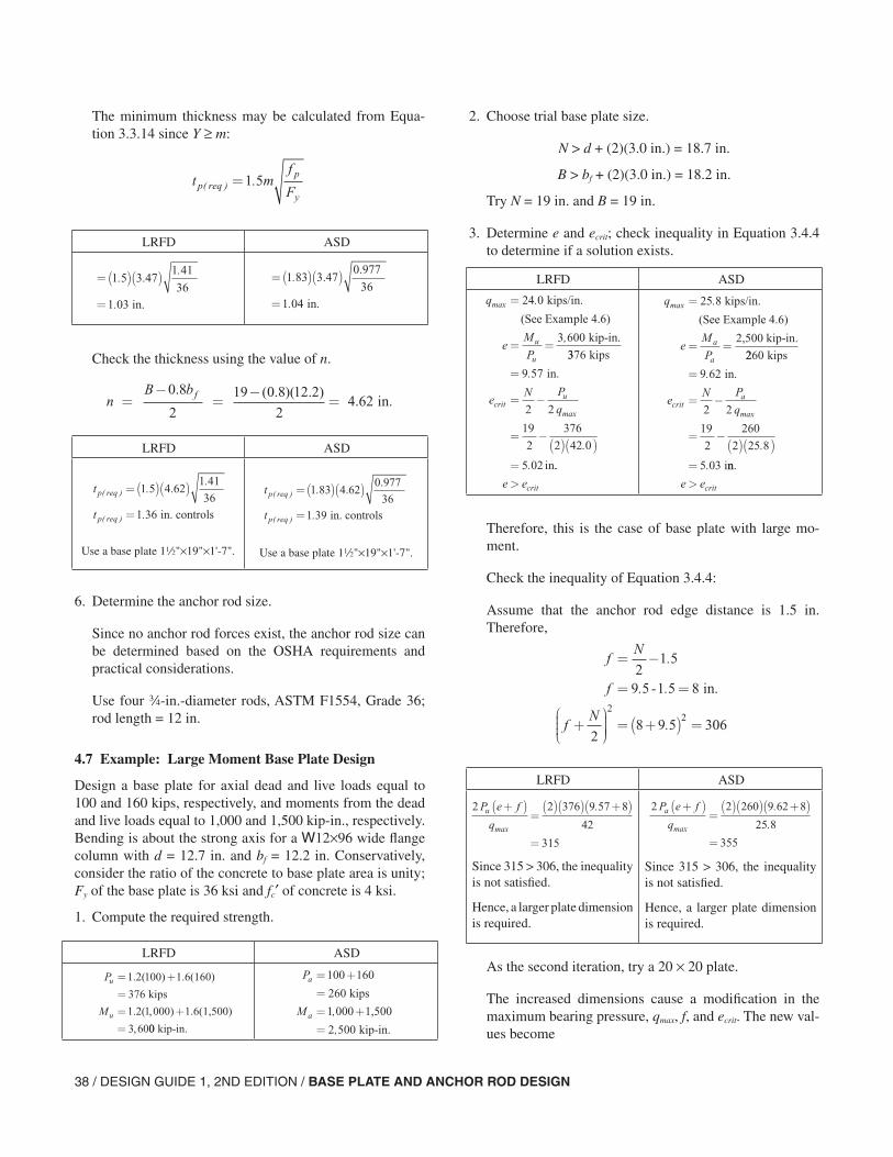
38 / DESIGN GUIDE 1, 2ND EDITION / BASE PLATE AND ANCHOR ROD DESIGN
The minimum thickness may be calculated from Equa-tion 3.3.14 since Y ≥ m:
Check the thickness using the value of n.
6. Determine the anchor rod size.
Since no anchor rod forces exist, the anchor rod size can be determined based on the OSHA requirements and practical considerations.
Use four w-in.-diameter rods, ASTM F1554, Grade 36; rod length = 12 in.
4.7 Example: Large Moment Base Plate Design
Design a base plate for axial dead and live loads equal to 100 and 160 kips, respectively, and moments from the dead and live loads equal to 1,000 and 1,500 kip-in., respectively. Bending is about the strong axis for a W12×96 wide flange column with d = 12.7 in. and bf = 12.2 in. Conservatively, consider the ratio of the concrete to base plate area is unity; Fy of the base plate is 36 ksi and fc′ of concrete is 4 ksi.
1. Compute the required strength.
LRFD ASD
t mf
Fp reqp
y( ) .=1 5
=( )( )
=
1 51 41
1 03
..
.
3.47
36 in.
=( )( )
=
1 83
1 04
.
.
3.470.977
36 in.
nB bf in.=−
=−
=0 8
2
19 0 8 12 2
24 62
. ( . )( . ).
LRFD ASD
Use a base plate 12"×19"×1'-7". Use a base plate 12"×19"×1'-7".
t
t
p req
p req
( )
( )
..
.
=( )( )
=
1 51 41
1 36
4.62
36 in. controls
t
t
p req
p req
( )
( )
.
.
=( )( )
=
1 83
1 39
4.620.977
36 in. controls
LRFD ASD
P
M
u
u
= +
== +
=
1 2 100
376
1 2 1 000
3 60
. (
. ( ,
,
) 1.6(160)
kips
) 1.6(1,500)
00 kip-in.
P
M
a
a
= +
== +
=
100
260
1 000
2 500
160
kips
1,500
kip-in.
,
,
2. Choose trial base plate size.
N > d + (2)(3.0 in.) = 18.7 in.
B > bf + (2)(3.0 in.) = 18.2 in.
Try N = 19 in. and B = 19 in.
3. Determine e and ecrit; check inequality in Equation 3.4.4 to determine if a solution exists.
Therefore, this is the case of base plate with large mo-ment.
Check the inequality of Equation 3.4.4:
Assume that the anchor rod edge distance is 1.5 in. Therefore,
As the second iteration, try a 20 × 20 plate.
The increased dimensions cause a modification in the maximum bearing pressure, qmax, f, and ecrit. The new val-ues become
LRFD ASD
q
eM
Pu
u
max .
,
=
= =
24 0
3 600
kips/in.
(See Example 4.6)
kip-in.
3376
9 57
2 2
19
2
376
2 42 0
5 02
kips
in.
in
=
= −
= −( )( )
=
.
.
.
max
eN P
qcritu
..
e ecrit>
q
eM
Pa
a
max .=
= =
25 8 kips/in.
(See Example 4.6)
2,500 kip-in.
2260
9 62
2 2
19
2
260
2 25 8
5 03
kips
in.
i
=
= −
= −( )( )
=
.
.
.
max
eN P
qcrita
nn.
e ecrit>
fN
f
fN
= −
= =
+
= +( ) =
21 5
9 5 1 5 8
28 9 5 306
22
.
. - .
.
in.
LRFD ASD
Since 315 > 306, the inequality is not satisfied.
Hence, a larger plate dimension is required.
Since 315 > 306, the inequality is not satisfied.
Hence, a larger plate dimension is required.
2 2 376 9 57 8
42
315
P e f
qu +( )
=( )( ) +( )
=max
. 2 2 260 9 62 8
25 8
355
P e f
qa +( )
=( )( ) +( )
=max
.
.
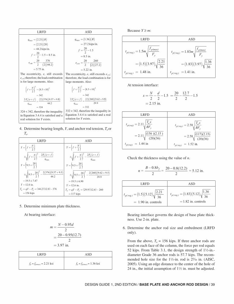
DESIGN GUIDE 1, 2ND EDITION / BASE PLATE AND ANCHOR ROD DESIGN / 39
4. Determine bearing length, Y, and anchor rod tension, Tu or Ta.
5. Determine minimum plate thickness.
At bearing interface:
LRFD ASD
The eccentricity, e, still exceeds ecrit; therefore, the load combination is for large moments. Also:
324 < 342, therefore the inequality in Equation 3.4.4 is satisfied and a real solution for Y exists.
The eccentricity, e, still exceeds ecrit; therefore, the load combination is for large moments. Also:
332 < 342, therefore the inequality in Equation 3.4.4 is satisfied and a real solution for Y exists.
q B
f
ecr
max .
.
.
. .
=( )( )=( )( )=
= − =
2 21
2 21 20
44 2
20
21 5 8 5
kips/in.
in.
iit = −( )( )
=
20
2
376
2 44 2
5 75
.
. in.
fN
P e f
qu
+
= +( )
=
+( )=( )( ) +
28 5 10
342
2 2 376 9 57 9
22
.
. .
max
55
44 2
324
( )
=
.
q B
f
ecrit
max .
.
.
.
=( )( )=
= −
=
= −
1 36
27 2
20
21 5
8 5
20
2
260
2
kips/in.
in.
(( )( )=
27 2
5 22
.
. in.
fN
P e f
qa
+
= +( )
=
+( )=( )( ) +
28 5 10
342
2 2 260 9 62 9
22
.
. .
max
55
29 9
332
( )
=
.
LRFD ASD
Y fN
fN P e f
q
Y
u
= +
± +
−
+( )
= +
2
2
2
9 520
2
2
max
.
± +
−
( ) +( )
= ±
9 520
2
2 376 9 57 9 5
44 2
19 5 7
2
.. .
.
. ..
.
. .
47
12 0
44 2 12 0 376
156
Y
T qY Pu u
=
= − =( )( )−
=
in.
kips
Y fN
fN P e f
q
Y
a
= +
± +
−
+( )
= +
2
2
2
9 520
2
2
max
.
± +
−
( ) +( )
= ±
9 520
2
2 260 9 62 9 5
29 9
19 5 6
2
.. .
.
. ..
.
. .
90
12 6
29 9 12 6 260
117
Y
T qY Pa a
=
= − =( )( )−
=
in.
kips
mN d
=−
=−
=
0 95
22 0 95 12 7
23 97
.
. ( .
.
0 )
in.
LRFD ASD
fp = fp(max) = 2.21 ksi fp = fp(max) = 1.36 ksi
Because Y ≥ m:
At tension interface:
Check the thickness using the value of n.
Bearing interface governs the design of base plate thick-ness. Use 2-in. plate.
6. Determine the anchor rod size and embedment (LRFD only).
From the above, Tu = 156 kips. If three anchor rods are used on each face of the column, the force per rod equals 52 kips. From Table 3.1, the design strength of 12-in.-diameter Grade 36 anchor rods is 57.7 kips. The recom-mended hole size for the 12-in. rod is 2c in. (AISC, 2005). Using an edge distance to the center of the hole of 24 in., the initial assumption of 12 in. must be adjusted.
LRFD ASD
t mf
F
t
p reqp
y
p req
( )(max)
( )
.
..
.
=
=( )( )
=
1 5
1 52 21
361 48
3.97
in.
t mf
F
t
p reqp
y
p req
( )(max)
( )
.
..
.
=
=( )( )
=
1 83
1 831 36
361 41
3.97
in.
xN d
= − − = − −
=2 2
1 512 7
21 5
2 15
..
.
.
20
2 in.
LRFD ASD
tT x
BF
t
p requ
y
p req
( )
( )
.
.(
(
.
=
=
=
2 11
2 11156
20
1 44
)(2.15 )
)(36)
in
tT x
BF
t
p reqa
y
p req
( )
( )
.
.
.
=
=
=
2 58
2 58117
20
1 52
(
(
)(2.15)
)(36)
inn.
nB bf =
0.8
2=
20 0.8(12.2)
2 = 5.12 in.
− −
LRFD ASD
t p req( ) .
.
=( )( )
=
1 5
1 90
5.122.21
36 in. controls
t p req( ) .
.
=( )( )
=
1 83
1 82
5.121.36
36 in. controls
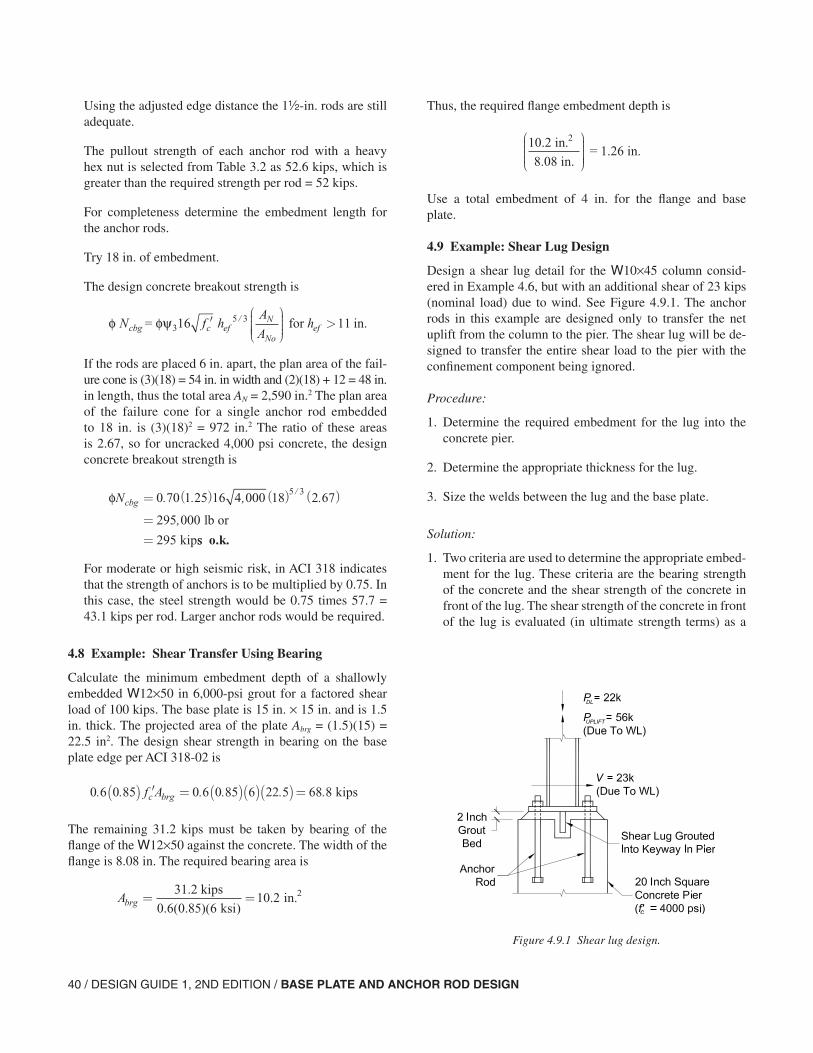
40 / DESIGN GUIDE 1, 2ND EDITION / BASE PLATE AND ANCHOR ROD DESIGN
Using the adjusted edge distance the 1-in. rods are still adequate.
The pullout strength of each anchor rod with a heavy hex nut is selected from Table 3.2 as 52.6 kips, which is greater than the required strength per rod = 52 kips.
For completeness determine the embedment length for the anchor rods.
Try 18 in. of embedment.
The design concrete breakout strength is
If the rods are placed 6 in. apart, the plan area of the fail-ure cone is (3)(18) = 54 in. in width and (2)(18) + 12 = 48 in. in length, thus the total area AN = 2,590 in.2 The plan area of the failure cone for a single anchor rod embedded to 18 in. is (3)(18)2 = 972 in.2 The ratio of these areas is 2.67, so for uncracked 4,000 psi concrete, the design concrete breakout strength is
For moderate or high seismic risk, in ACI 318 indicates that the strength of anchors is to be multiplied by 0.75. In this case, the steel strength would be 0.75 times 57.7 = 43.1 kips per rod. Larger anchor rods would be required.
4.8 Example: Shear Transfer Using Bearing
Calculate the minimum embedment depth of a shallowly embedded W12×50 in 6,000-psi grout for a factored shear load of 100 kips. The base plate is 15 in. × 15 in. and is 1.5 in. thick. The projected area of the plate Abrg = (1.5)(15) = 22.5 in2. The design shear strength in bearing on the base plate edge per ACI 318-02 is
The remaining 31.2 kips must be taken by bearing of the flange of the W12×50 against the concrete. The width of the flange is 8.08 in. The required bearing area is
φ φψ = for in.3N f hA
Ahcbg c ef
N
Noef16 115 3′
>/
φNcbg = ( ) ( ) ( )
==
0 70 1 25 16 4 000 18 2 67
295 000
295
5 3. . , .
,
/
lb or
kipss o.k.
0 6 0 85 0 6 0 85 6 22 5 68 8. . . . . .( ) ′ = ( )( )( )=f Ac brg kips
Abrg = =31.2 kips
ksi in.2
0 6 0 85 610 2
. ( . )( ).
Thus, the required flange embedment depth is
Use a total embedment of 4 in. for the flange and base plate.
4.9 Example: Shear Lug Design
Design a shear lug detail for the W10×45 column consid-ered in Example 4.6, but with an additional shear of 23 kips (nominal load) due to wind. See Figure 4.9.1. The anchor rods in this example are designed only to transfer the net uplift from the column to the pier. The shear lug will be de-signed to transfer the entire shear load to the pier with the confinement component being ignored.
Procedure:
1. Determine the required embedment for the lug into the concrete pier.
2. Determine the appropriate thickness for the lug.
3. Size the welds between the lug and the base plate.
Solution:
1. Two criteria are used to determine the appropriate embed-ment for the lug. These criteria are the bearing strength of the concrete and the shear strength of the concrete in front of the lug. The shear strength of the concrete in front of the lug is evaluated (in ultimate strength terms) as a
10.2 in.
8.08 in. = 1.26 in.
2
Figure 4.9.1 Shear lug design.
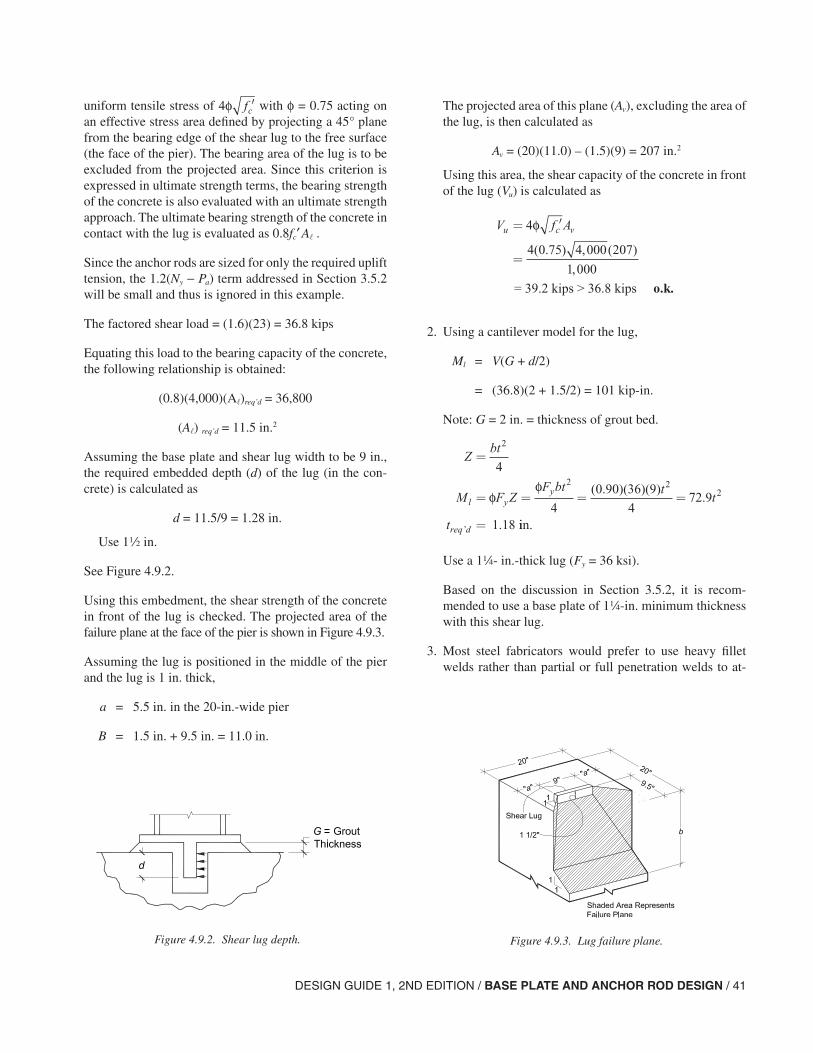
DESIGN GUIDE 1, 2ND EDITION / BASE PLATE AND ANCHOR ROD DESIGN / 41
The projected area of this plane (Av), excluding the area of the lug, is then calculated as
Av = (20)(11.0) – (1.5)(9) = 207 in.2
Using this area, the shear capacity of the concrete in front of the lug (Vu) is calculated as
2. Using a cantilever model for the lug,
Ml = V(G + d/2)
= (36.8)(2 + 1.5/2) = 101 kip-in.
Note: G = 2 in. = thickness of grout bed.
Use a 14- in.-thick lug (Fy = 36 ksi).
Based on the discussion in Section 3.5.2, it is recom-mended to use a base plate of 14-in. minimum thickness with this shear lug.
3. Most steel fabricators would prefer to use heavy fillet welds rather than partial or full penetration welds to at-
uniform tensile stress of with φ = 0.75 acting on an effective stress area defined by projecting a 45° plane from the bearing edge of the shear lug to the free surface (the face of the pier). The bearing area of the lug is to be excluded from the projected area. Since this criterion is expressed in ultimate strength terms, the bearing strength of the concrete is also evaluated with an ultimate strength approach. The ultimate bearing strength of the concrete in contact with the lug is evaluated as 0.8fc′ A .
Since the anchor rods are sized for only the required uplift tension, the 1.2(Ny − Pa) term addressed in Section 3.5.2 will be small and thus is ignored in this example.
The factored shear load = (1.6)(23) = 36.8 kips
Equating this load to the bearing capacity of the concrete, the following relationship is obtained:
(0.8)(4,000)(A)req’d = 36,800
(A) req’d = 11.5 in.2
Assuming the base plate and shear lug width to be 9 in., the required embedded depth (d) of the lug (in the con-crete) is calculated as
d = 11.5/9 = 1.28 in.
Use 12 in.
See Figure 4.9.2.
Using this embedment, the shear strength of the concrete in front of the lug is checked. The projected area of the failure plane at the face of the pier is shown in Figure 4.9.3.
Assuming the lug is positioned in the middle of the pier and the lug is 1 in. thick,
a = 5.5 in. in the 20-in.-wide pier
B = 1.5 in. + 9.5 in. = 11.0 in.
4φ ′fc
Figure 4.9.2. Shear lug depth. Figure 4.9.3. Lug failure plane.
V f Au c v= ′
=
4
4 0 75 4 000 207
1 000
φ
( . ) , ( )
,
= 39.2 kips > 36.8 kips o.k.
Zbt
M F ZF bt t
t
t
l yy
req d
=
= = = =
=
2
2 22
4
4
0 90 36 9
472 9
1 18
φφ ( . )( )( )
.
.’ iin.
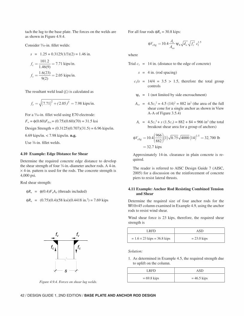
42 / DESIGN GUIDE 1, 2ND EDITION / BASE PLATE AND ANCHOR ROD DESIGN
tach the lug to the base plate. The forces on the welds are as shown in Figure 4.9.4.
Consider c-in. fillet welds:
s = 1.25 + 0.3125(1/3)(2) = 1.46 in.
The resultant weld load (fr) is calculated as
For a c-in. fillet weld using E70 electrode:
Fw = φ(0.60)FExx = (0.75)(0.60)(70) = 31.5 ksi
Design Strength = (0.3125)(0.707)(31.5) = 6.96 kips/in.
6.69 kips/in. < 7.98 kips/in. n.g.
Use a-in. fillet welds.
4.10 Example: Edge Distance for Shear
Determine the required concrete edge distance to develop the shear strength of four w-in.-diameter anchor rods. A 4-in. × 4-in. pattern is used for the rods. The concrete strength is 4,000 psi.
Rod shear strength:
φRn = φ(0.4)FuAb (threads included)
φRn = (0.75)(0.4)(58 ksi)(0.4418 in.2) = 7.69 kips
f
f
c
v
= =
= =
101 2
1 46 97 71
1 6 23
9 22 05
.
. ( ).
. ( )
( ).
kips/in.
kips/in.
Figure 4.9.4. Forces on shear lug welds.
fr = ( ) + =7 71 2 05 7 982 2. ( . ) . kips/in.
For all four rods φRn = 30.8 kips:
where
Trial c1 = 14 in. (distance to the edge of concrete)
s = 4 in. (rod spacing)
c1/s = 14/4 = 3.5 > 1.5, therefore the total group controls
ψ6 = 1 (not limited by side encroachment)
Avo = 4.5c12 = 4.5 (14)2 = 882 in2 (the area of the full
shear cone for a single anchor as shown in View A-A of Figure 3.5.4)
Av = 4.5c12 + s (1.5c1) = 882 + 84 = 966 in2 (the total
breakout shear area for a group of anchors)
Approximately 14-in. clearance in plain concrete is re-quired.
The reader is referred to AISC Design Guide 7 (AISC, 2005) for a discussion on the reinforcement of concrete piers to resist lateral thrusts.
4.11 Example: Anchor Rod Resisting Combined Tension and Shear
Determine the required size of four anchor rods for the W10×45 column examined in Example 4.9, using the anchor rods to resist wind shear.
Wind shear force is 23 kips, therefore, the required shear strength is
Solution:
1. As determined in Example 4.5, the required strength due to uplift on the column.
φ ψVA
Ad f ccbg
v
voo c= ′10 4 6 1
1 5. .
φVcbg =
( ) ( ) =
=
10 4966
8821 0 75 4000 14 32 700
32
1 5. . ,
. lb
..7 kips
LRFD ASD
= 1.6 × 23 kips = 36.8 kips = 23.0 kips
LRFD ASD
= 69.8 kips = 46.5 kips
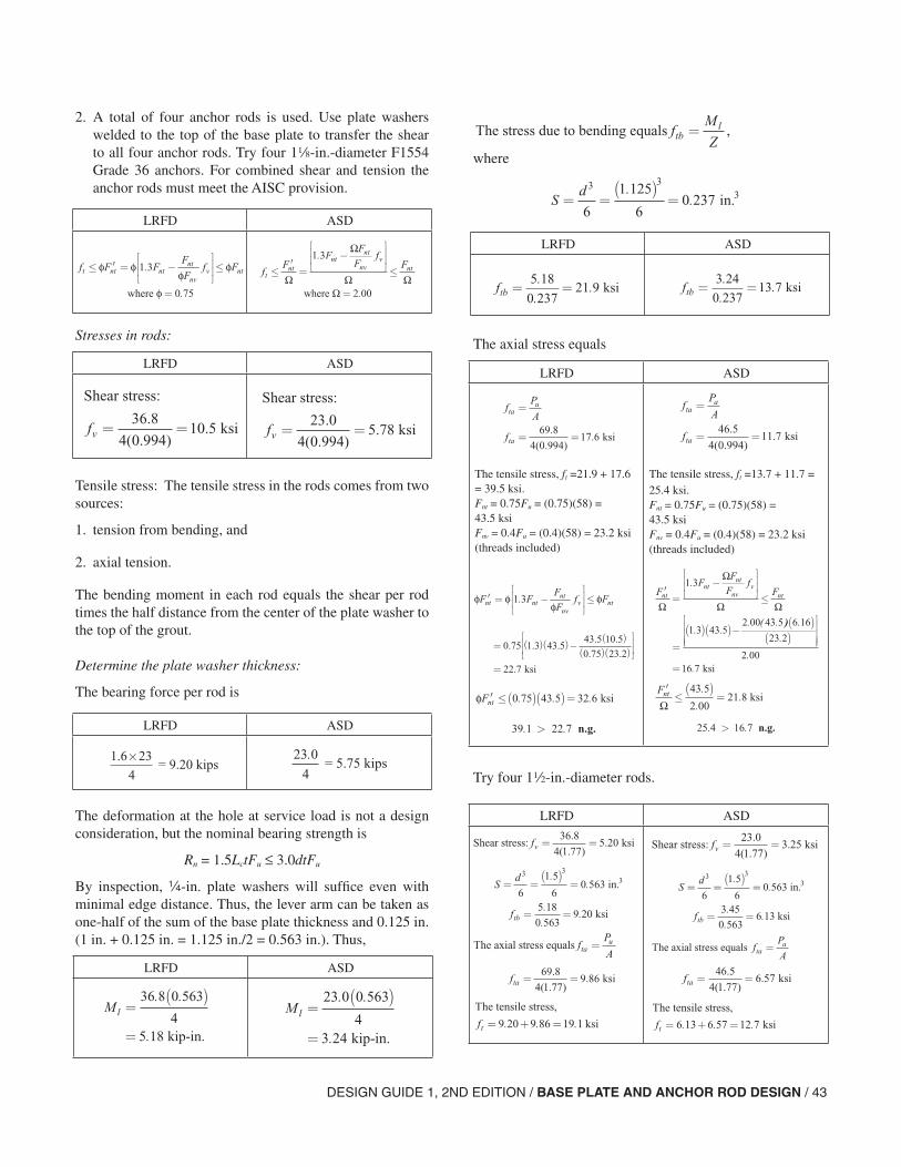
DESIGN GUIDE 1, 2ND EDITION / BASE PLATE AND ANCHOR ROD DESIGN / 43
2. A total of four anchor rods is used. Use plate washers welded to the top of the base plate to transfer the shear to all four anchor rods. Try four 18-in.-diameter F1554 Grade 36 anchors. For combined shear and tension the anchor rods must meet the AISC provision.
Stresses in rods:
Tensile stress: The tensile stress in the rods comes from two sources:
1. tension from bending, and
2. axial tension.
The bending moment in each rod equals the shear per rod times the half distance from the center of the plate washer to the top of the grout.
Determine the plate washer thickness:
The bearing force per rod is
The deformation at the hole at service load is not a design consideration, but the nominal bearing strength is
Rn = 1.5LctFu ≤ 3.0dtFu
By inspection, -in. plate washers will suffice even with minimal edge distance. Thus, the lever arm can be taken as one-half of the sum of the base plate thickness and 0.125 in. (1 in. + 0.125 in. = 1.125 in./2 = 0.563 in.). Thus,
LRFD ASD
f F FF
Ff Ft nt nt
nt
nvv nt≤ ′ = −
≤
=
φ φφ
φ
φ
1 3
0 75
.
.where
fF
FF
Ff
Ft
ntnt
nt
nvv
nt≤′=
−
≤
=Ω
Ω
Ω ΩΩ
1 3
2 00
.
.where
LRFD ASD
Shear stress:
ksifv = =36 8
4 0 99410 5
.
( . ).
Shear stress:
ksifv = =23 0
4 0 9945 78
.
( . ).
1.6 23 = 9.20 kips
×4
23 0
4
. = 5.75 kips
LRFD ASD
LRFD ASD
Ml =( )
=
36 8 0 563
45 18
. .
. kip-in.
Ml =( )
=
23 0 0 563
43 24
. .
. kip-in.
where
The axial stress equals
Try four 12-in.-diameter rods.
The stress due to bending equals ,fM
Ztbl=
Sd
= =( )
=3 3
6
1 125
60 237
.. in.3
LRFD ASD
ftb = =5 18
0 23721 9
.
.. ksi ftb = =
3 24
0 23713 7
.
.. ksi
LRFD ASD
The tensile stress, ft =21.9 + 17.6 = 39.5 ksi.Fnt = 0.75Fu = (0.75)(58) = 43.5 ksiFnv = 0.4Fu = (0.4)(58) = 23.2 ksi (threads included)
The tensile stress, ft =13.7 + 11.7 = 25.4 ksi.Fnt = 0.75Fu = (0.75)(58) = 43.5 ksiFnv = 0.4Fu = (0.4)(58) = 23.2 ksi (threads included)
fP
A
f
tau
ta
=
= =69 8
4 0 99417 6
.
( . ). ksi
fP
A
f
taa
ta
=
= =46 5
4 0 99411 7
.
( . ). ksi
φ φφ
φ′ = −
≤F F
F
Ff Fnt nt
nt
nvv nt1 3.
′=
−
≤
=
( )( )−
FF
F
Ff
Fntnt
nt
nvv
nt
Ω
Ω
Ω Ω
1 3
1 3 43 52 00 43 5
.
. .. ( . )) .
.
..
6 16
23 2
2 0016 7
( )( )
= ksi
φ ′ ≤( )( )=Fnt 0 75 43 5 32 6. . . ksi ′≤( )
=Fnt
Ω43 5
2 0021 8
.
.. ksi
39 1 22 7. . > n.g. 25 4 16 7. . > n.g.
LRFD ASD
Shear stress: ksifv = =36 8
4 1 775 20
.
( . ).
Sd
ftb
= =( )
=
= =
3 3
6
1 5
60 563
5 18
0 5639 20
..
.
..
in.
ksi
3
The axial stress equals fP
Atau=
fta = =69 8
4 1 779 86
.
( . ). ksi
The tensile stress,
ksift = + =9 20 9 86 19 1. . .
Shear stress: ksifv = =23 0
4 1 773 25
.
( . ).
Sd
ftb
= =( )
=
= =
3 3
6
1 5
60 563
3 45
0 5636 13
..
.
..
in.
ksi
3
The axial stress equals fP
Ataa=
fta = =46 5
4 1 776 57
.
( . ). ksi
The tensile stress,
ksift = + =6 13 6 57 12 7. . .
= ( )( )−( )
( )( )
=
0 75 1 3 43 543 5 10 5
0 75 23 2
22 7
. . .. .
. .
. ksi
44 / DESIGN GUIDE 1, 2ND EDITION / BASE PLATE AND ANCHOR ROD DESIGN
can be neglected in the rods, but the 0.8 reduction in shear capacity per ACI 318 is included. Rather than using the 0.8 reduction, use a 1.25 magnifier on the shear load.
Due to the size of the rods they will have to be positioned beyond the column flanges.
As a matter of interest, assume that welded washers are not provided. It should be noted that a slip of w in. could oc-cur before the anchor rods go into bearing. Check the 12-in. anchor rods using the author’s suggestion that only two an-chor rods be considered to carry the shear; however, bending
= 32.6 ksi
30.1 < 32.6 o.k.
Use four 12-in.-diameter rods.
20.1 < 21.8 o.k.
Use four 12-in.-diameter rods.
φ ′ = ( )( )−( )
( )( )
Fnt 0.75 1 3 43 543 5 5 20
0 75 23 2. .
. .
. .
′=
( )( )−( )
( )
Fnt
Ω
1 3 43 52 00 43 5 3 25
23 2
2 00
. .. ( . ) .
.
.
LRFD ASD
9.9 ksi < 18.0 ksi o.k. 6.6 ksi < 13.1 ksi o.k.
f
f
v
ta
=( )( )
=
= =
1 25 36 8
2 1 7713 0
69 8
4 1 779 9
. .
( . ).
.
( . ).
ksi
ksi
f
f
v
ta
=( )( )
=
= =
1 25 23
2 1 778 12
46 5
4 1 776 6
.
( . ).
.
( . ).
ksi
ksi
= 32 7. ksi =
≤( )
=
=
22 2
43 5
2 0021 8
21 8
.
.
..
.
ksi
ksi
ksi
≤( )( )=0 75 43 5 32 6. . . ksi
= ( )( )−( )
( )( )
0 75 1 3 43 5
43 5 13 0
0 75 23 2. . .
. .
. .
φ φφ
φ′ = −
≤F F
F
Ff Fnt nt
nt
ntv nt1 3.
′=
−
≤
FF
F
Ff
Fntnt
nt
ntv
nt
Ω
Ω
Ω Ω
1 3.
=( )( )−
( )( )( )
1 3 43 5
2 00 43 5 8 1223 2
2 00
. .. . .
..
=13 1. ksi=18 0. ksi
REFERENCES
ACI 117 (1990), Standard Specifications for Tolerances for Concrete Construction and Materials (ACI 117-90 (Re-approved 2002), Farmington Hills, MI.
ACI 349 (2001), Code Requirements for Nuclear Safety Related Concrete Structures and Commentary (ACI 349-01/349R-01), Farmington Hills, MI.
ACI Committee 318 (2002), Building Code Requirements for Structural Concrete (ACI 318-02) and Commentary (ACI 318R-02), Farmington Hills, MI.
American Institute of Steel Construction (2001), Manual of Steel Construction, Load Resistance Factor Design, Chi-cago, IL.
American Institute of Steel Construction (2005), Specifica-tion for Structural Steel Buildings, Chicago, IL.
American Institute of Steel Construction (2005), Seismic Provisions for Structural Steel Buildings, Chicago, IL.
American Institute of Steel Construction (2005), Code of Standard Practice for Steel Buildings and Bridges, Chi-cago, IL.
DeWolf, J.T. and Ricker, D.T. (1990), Design Guide No. 1, Column Base Plates, Steel Design Guide Series, AISC, Chicago, IL.
Drake, R.M. and Elkin, S.J. (1999), “Beam-Column Base Plate Design—LRFD Method,” Engineering Journal, Vol. 36, No. 1, First Quarter, AISC, Chicago, IL.
Fisher, J.M. (2004), Design Guide No. 7, Industrial Build-ings—Roofs to Anchor Rods, 2nd Ed., Steel Design Guide Series, AISC, Chicago, IL.
Fisher, J.M. (1981), “Structural Details in Industrial Buildings,” Engineering Journal, Third Quarter, AISC, Chicago, IL.
Fisher, J.M. and West, M.A. (1997), Design Guide No. 10, Erection Bracing of Low-Rise Structural Steel Frames,” Steel Design Guide Series, AISC, Chicago, IL.
Fisher, J.M. and Doyle, J.M. (2005), “Discussion: Beam-Column Base Plate Design—LRFD Method,” Engineer-ing Journal, Vol. 36, No. 1, Fourth Quarter, AISC, Chi-cago, IL.
Frank, K.H. (1980), “Fatigue Strength of Anchor Bolts,” ASCE Journal of the Structural Division, Vol. 106, No. ST, June.
Kaczinski, M.R., Dexter, R.J., and Van Dien, J.P. (1996), “Fatigue-Resistant Design of Cantilevered Signal, Sign, and Light Supports,” National Cooperative Highway Re-search Program, NCHRP Report 412, Transportation Re-search Board, Washington D.C.
Koenigs, M.T., Botros, T.A., Freytag, D., and Frank, K.H. (2003), “Fatigue Strength of Signal Mast Arm Connec-tions,” Report No. FHWA/TX-04/4178-2, August.
Occupational Safety and Health Administration (2001), OSHA, Safety Standards for Steel Erection, (Subpart R of 29 CFR Part 1926), Washington, D.C.
Research Council on Structural Connections (2004), Speci-fication for Structural Joints Using ASTM A325 or A490 Bolts, available from AISC, Chicago, IL.
Thornton, W.A. (1990), “Design of Small Base Plates for Wide-Flange Columns,” Engineering Journal, Vol. 27, No. 3, Third Quarter, AISC, Chicago, IL.
Till, R.D. and Lefke, N.A. (1994), “The Relationship Be-tween Torque, Tension, and Nut Rotation of Large Diam-eter Anchor Bolts,” Materials and Technology Division, Michigan Department of Transportation, October.
Wald, F., Sokol, Z., and Steenhuis, M. (1995), “Proposal of the Stiffness Design Model of the Column Bases,” Pro-ceedings of the Third International Workshop on Connec-tions in Steel Structures, Trento, Italy.
DESIGN GUIDE 1, 2ND EDITION / BASE PLATE AND ANCHOR ROD DESIGN/ 45

46 / DESIGN GUIDE 1, 2ND EDITION / BASE PLATE AND ANCHOR ROD DESIGN
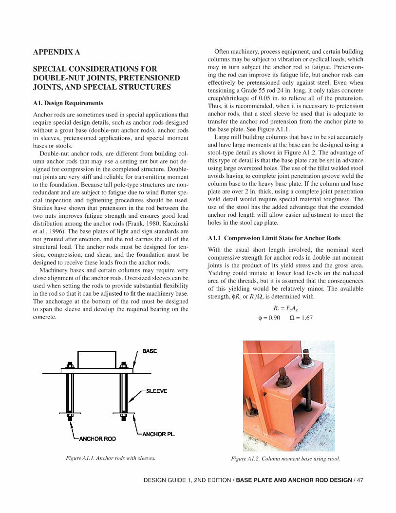
DESIGN GUIDE 1, 2ND EDITION / BASE PLATE AND ANCHOR ROD DESIGN / 47
APPENDIX A
SPECIAL CONSIDERATIONS FOR DOUBLE-NUT JOINTS, PRETENSIONED JOINTS, AND SPECIAL STRUCTURES
A1. Design Requirements
Anchor rods are sometimes used in special applications that require special design details, such as anchor rods designed without a grout base (double-nut anchor rods), anchor rods in sleeves, pretensioned applications, and special moment bases or stools.
Double-nut anchor rods, are different from building col-umn anchor rods that may use a setting nut but are not de-signed for compression in the completed structure. Double-nut joints are very stiff and reliable for transmitting moment to the foundation. Because tall pole-type structures are non-redundant and are subject to fatigue due to wind flutter spe-cial inspection and tightening procedures should be used. Studies have shown that pretension in the rod between the two nuts improves fatigue strength and ensures good load distribution among the anchor rods (Frank, 1980; Kaczinski et al., 1996). The base plates of light and sign standards are not grouted after erection, and the rod carries the all of the structural load. The anchor rods must be designed for ten-sion, compression, and shear, and the foundation must be designed to receive these loads from the anchor rods.
Machinery bases and certain columns may require very close alignment of the anchor rods. Oversized sleeves can be used when setting the rods to provide substantial flexibility in the rod so that it can be adjusted to fit the machinery base. The anchorage at the bottom of the rod must be designed to span the sleeve and develop the required bearing on the concrete.
Often machinery, process equipment, and certain building columns may be subject to vibration or cyclical loads, which may in turn subject the anchor rod to fatigue. Pretension-ing the rod can improve its fatigue life, but anchor rods can effectively be pretensioned only against steel. Even when tensioning a Grade 55 rod 24 in. long, it only takes concrete creep/shrinkage of 0.05 in. to relieve all of the pretension. Thus, it is recommended, when it is necessary to pretension anchor rods, that a steel sleeve be used that is adequate to transfer the anchor rod pretension from the anchor plate to the base plate. See Figure A1.1.
Large mill building columns that have to be set accurately and have large moments at the base can be designed using a stool-type detail as shown in Figure A1.2. The advantage of this type of detail is that the base plate can be set in advance using large oversized holes. The use of the fillet welded stool avoids having to complete joint penetration groove weld the column base to the heavy base plate. If the column and base plate are over 2 in. thick, using a complete joint penetration weld detail would require special material toughness. The use of the stool has the added advantage that the extended anchor rod length will allow easier adjustment to meet the holes in the stool cap plate.
A1.1 Compression Limit State for Anchor Rods
With the usual short length involved, the nominal steel compressive strength for anchor rods in double-nut moment joints is the product of its yield stress and the gross area. Yielding could initiate at lower load levels on the reduced area of the threads, but it is assumed that the consequences of this yielding would be relatively minor. The available strength, φRc or Rc/Ω, is determined with
Rc = FyAg
φ = 0.90 Ω = 1.67
Figure A1.1. Anchor rods with sleeves. Figure A1.2. Column moment base using stool.
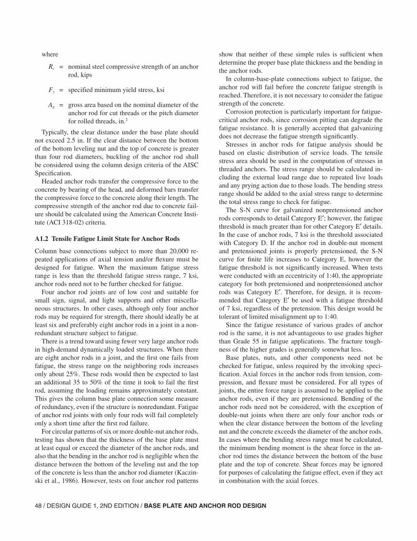
48 / DESIGN GUIDE 1, 2ND EDITION / BASE PLATE AND ANCHOR ROD DESIGN
where
Rc = nominal steel compressive strength of an anchor rod, kips
Fy = specified minimum yield stress, ksi
Ag = gross area based on the nominal diameter of the anchor rod for cut threads or the pitch diameter for rolled threads, in.2
Typically, the clear distance under the base plate should not exceed 2.5 in. If the clear distance between the bottom of the bottom leveling nut and the top of concrete is greater than four rod diameters, buckling of the anchor rod shall be considered using the column design criteria of the AISC Specification.
Headed anchor rods transfer the compressive force to the concrete by bearing of the head, and deformed bars transfer the compressive force to the concrete along their length. The compressive strength of the anchor rod due to concrete fail-ure should be calculated using the American Concrete Insti-tute (ACI 318-02) criteria.
A1.2 Tensile Fatigue Limit State for Anchor Rods
Column base connections subject to more than 20,000 re-peated applications of axial tension and/or flexure must be designed for fatigue. When the maximum fatigue stress range is less than the threshold fatigue stress range, 7 ksi, anchor rods need not to be further checked for fatigue.
Four anchor rod joints are of low cost and suitable for small sign, signal, and light supports and other miscella-neous structures. In other cases, although only four anchor rods may be required for strength, there should ideally be at least six and preferably eight anchor rods in a joint in a non-redundant structure subject to fatigue.
There is a trend toward using fewer very large anchor rods in high-demand dynamically loaded structures. When there are eight anchor rods in a joint, and the first one fails from fatigue, the stress range on the neighboring rods increases only about 25%. These rods would then be expected to last an additional 35 to 50% of the time it took to fail the first rod, assuming the loading remains approximately constant. This gives the column base plate connection some measure of redundancy, even if the structure is nonredundant. Fatigue of anchor rod joints with only four rods will fail completely only a short time after the first rod failure.
For circular patterns of six or more double-nut anchor rods, testing has shown that the thickness of the base plate must at least equal or exceed the diameter of the anchor rods, and also that the bending in the anchor rod is negligible when the distance between the bottom of the leveling nut and the top of the concrete is less than the anchor rod diameter (Kaczin-ski et al., 1986). However, tests on four anchor rod patterns
show that neither of these simple rules is sufficient when determine the proper base plate thickness and the bending in the anchor rods.
In column-base-plate connections subject to fatigue, the anchor rod will fail before the concrete fatigue strength is reached. Therefore, it is not necessary to consider the fatigue strength of the concrete.
Corrosion protection is particularly important for fatigue-critical anchor rods, since corrosion pitting can degrade the fatigue resistance. It is generally accepted that galvanizing does not decrease the fatigue strength significantly.
Stresses in anchor rods for fatigue analysis should be based on elastic distribution of service loads. The tensile stress area should be used in the computation of stresses in threaded anchors. The stress range should be calculated in-cluding the external load range due to repeated live loads and any prying action due to those loads. The bending stress range should be added to the axial stress range to determine the total stress range to check for fatigue.
The S-N curve for galvanized nonpretensioned anchor rods corresponds to detail Category E′; however, the fatigue threshold is much greater than for other Category E′ details. In the case of anchor rods, 7 ksi is the threshold associated with Category D. If the anchor rod in double-nut moment and pretensioned joints is properly pretensioned, the S-N curve for finite life increases to Category E, however the fatigue threshold is not significantly increased. When tests were conducted with an eccentricity of 1:40, the appropriate category for both pretensioned and nonpretensioned anchor rods was Category E′. Therefore, for design, it is recom-mended that Category E′ be used with a fatigue threshold of 7 ksi, regardless of the pretension. This design would be tolerant of limited misalignment up to 1:40.
Since the fatigue resistance of various grades of anchor rod is the same, it is not advantageous to use grades higher than Grade 55 in fatigue applications. The fracture tough-ness of the higher grades is generally somewhat less.
Base plates, nuts, and other components need not be checked for fatigue, unless required by the invoking speci-fication. Axial forces in the anchor rods from tension, com-pression, and flexure must be considered. For all types of joints, the entire force range is assumed to be applied to the anchor rods, even if they are pretensioned. Bending of the anchor rods need not be considered, with the exception of double-nut joints when there are only four anchor rods or when the clear distance between the bottom of the leveling nut and the concrete exceeds the diameter of the anchor rods. In cases where the bending stress range must be calculated, the minimum bending moment is the shear force in the an-chor rod times the distance between the bottom of the base plate and the top of concrete. Shear forces may be ignored for purposes of calculating the fatigue effect, even if they act in combination with the axial forces.
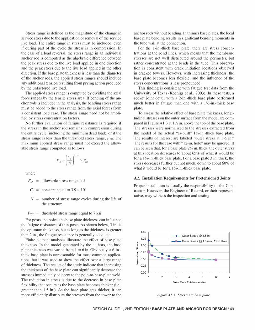
DESIGN GUIDE 1, 2ND EDITION / BASE PLATE AND ANCHOR ROD DESIGN / 49
Stress range is defined as the magnitude of the change in service stress due to the application or removal of the service live load. The entire range in stress must be included, even if during part of the cycle the stress is in compression. In the case of a load reversal, the stress range in an individual anchor rod is computed as the algebraic difference between the peak stress due to the live load applied in one direction and the peak stress due to the live load applied in the other direction. If the base plate thickness is less than the diameter of the anchor rods, the applied stress ranges should include any additional tension resulting from prying action produced by the unfactored live load.
The applied stress range is computed by dividing the axial force ranges by the tensile stress area. If bending of the an-chor rods is included in the analysis, the bending stress range must be added to the stress range from the axial forces from a consistent load case. The stress range need not be ampli-fied by stress concentration factors.
No further evaluation of fatigue resistance is required if the stress in the anchor rod remains in compression during the entire cycle (including the minimum dead load), or if the stress range is less than the threshold stress range, FTH. The maximum applied stress range must not exceed the allow-able stress range computed as follows:
where
FSR = allowable stress range, ksi
Cf = constant equal to 3.9 × 10⁸
N = number of stress range cycles during the life of the structure
FTH = threshold stress range equal to 7 ksi
For posts and poles, the base plate thickness can influence the fatigue resistance of thin posts. As shown below, 3 in. is the optimum thickness, but as long as the thickness is greater than 2 in., the fatigue resistance is generally adequate.
Finite-element analyses illustrate the effect of base plate thickness. In the model generated by the authors, the base plate thickness was varied from 1 to 6 in. Obviously, a 6-in.-thick base plate is unreasonable for most common applica-tions, but it was used to show the effect over a large range of thickness. The results of the study indicate that increasing the thickness of the base plate can significantly decrease the stresses immediately adjacent to the pole-to-base-plate weld. The reduction in stress is due to the decrease in base plate flexibility that occurs as the base plate becomes thicker (i.e., greater than 1.5 in.). As the base plate gets thicker, it can more efficiently distribute the stresses from the tower to the
FC
NFSR
f
TH= ≥
0 333.
anchor rods without bending. In thinner base plates, the local base plate bending results in significant bending moments in the tube wall at the connection.
For the 1-in.-thick base plate, there are stress concen-trations at the bend lines, which means that the membrane stresses are not well distributed around the perimeter, but rather concentrated at the bends in the tube. This observa-tion is consistent with crack initiation locations observed in cracked towers. However, with increasing thickness, the base plate becomes less flexible, and the influence of the stress concentrations is less pronounced.
This finding is consistent with fatigue test data from the University of Texas (Koenigs et al., 2003). In these tests, a socket joint detail with a 2-in.-thick base plate performed much better in fatigue than one with a 12-in.-thick base plate.
To assess the relative effect of base plate thickness, longi-tudinal stresses on the outer surface from the model are com-pared in Figure A1.3 at 12 in. above the top of the base plate. The stresses were normalized to the stresses extracted from the model of the actual “as-built” 14-in.-thick base plate. The results of interest are labeled “outer stress at 12 in.” The results for the case with “12-in. hole” may be ignored. It can be seen that, for a base plate 24 in. thick, the outer stress at this location decreases to about 65% of what it would be for a 14-in.-thick base plate. For a base plate 3 in. thick, the stress decreases further but not much, down to about 60% of what it would be for a 14-in.-thick base plate.
A2. Installation Requirements for Pretensioned Joints
Proper installation is usually the responsibility of the Con-tractor. However, the Engineer of Record, or their represen-tative, may witness the inspection and testing.
Figure A1.3. Stresses in base plate.
0.00
0.25
0.50
0.75
1.00
1.25
1.50
1 2 3 4 5 6 7
Base Plate Thickness (in)
No
rmal
ized
Str
ess
Outer Stress @ 1.5 in
Outer Stress @ 1.5 in w/ 12 in Hole
50 / DESIGN GUIDE 1, 2ND EDITION / BASE PLATE AND ANCHOR ROD DESIGN
In any anchor rod installation there will be some amount of misalignment. It is assumed that the tolerances will be stated in the invoking specification and that the tolerances correspond with the tolerances specified in the AISC Code of Standard Practice for Steel Buildings and Bridges. For anchor rods subjected to fatigue loading, it is also recom-mended that a tolerance for vertical misalignment of an-chor rods be specified as less than 1:40. Provisions should be made to minimize misalignments and to meet required tolerances. The best way to maintain alignment is the use of a template. Templates comprising rings with nuts on both sides at two locations along the length of the anchor rods are recommended.
Vibratory machine joints and double-nut joints designed for Seismic Design Category D or greater, according to ASCE 7, or designed for fatigue as described herein, require pretensioning. Failure to follow the nut tightening procedure can lead to inadequately pretensioned anchor rods and associated uneven distribution of loads among the contributing anchor rods. Inadequately tightened bolts can also lead to fatigue failures and further loosening of the nuts under cyclic loading. A less likely outcome of failure to follow the tightening procedure is tightening to the point of damage—plastic deformation and stripping of the threads—which may require removal and replacement.
The starting point for tightening procedures is between 20 to 30% of the final tension. For anchor rods, this is defined as a function of torque, as
Tv = 0.12 dbTm
where
Tv = verification torque (in.-kips)
db = nominal body diameter of the anchor rod (in.)
Tm = minimum installation pretension (kips) given in Table A1
Till (1994) has shown that a multiplier of 0.12 in this re-lationship is adequate for common sizes and coatings of an-chor rods. Other researchers have suggested a value of 0.20 for less-well-lubricated rods.
If an anchor rod has a nut head or the head is fastened with nuts, the nut should be prevented from rotation while the anchor rod is tightened. This can be achieved with a jam nut or another type of locking device. The jam nut will affect the ultimate or fatigue strength of the rod.
Very large torques may be required to properly tighten an-chor rods greater than 1 in. in diameter. A slugging wrench or a hydraulic torque wrench is required. For the leveling nuts, an open-end slugging wrench may be used.
A2.1 Double-Nut Joints
Prior to installation of anchor rods in a double-nut-moment joint, an anchor-rod rotation capacity test should be per-formed with at least one anchor rod from each lot. This test attempts to recreate the conditions to which the anchor rod will be subjected during installation.
After the test and before placing the concrete, anchor rods should be secured to a template or other device to avoid movement during placing and curing of the concrete that may lead to misalignments larger than what may be toler-ated. The hole pattern in the template should be verified by comparing the top template to the base plate to be erected if it is on site.
Beveled washers should be used:
1. Under the leveling nut if the slope of the bottom face of the base plate has a slope greater than 1:20.
2. Under the leveling nut if the leveling nut could not be brought into firm contact with the base plate.
3. Under the top nut if the slope of the top face of the base plate has a slope greater than 1:20.
4. Under the top nut if the top nut could not be brought into firm contact with the base plate.
If a beveled washer is required, the contractor should dis-assemble the joint, replace nuts, add the beveled washer(s), and retighten in a star pattern to the initial condition. Bev-eled washers can typically accommodate a slope up to 1:6.
Top nuts should be pretensioned. The procedure for pre-tensioning is a turn-of-nut procedure, although they are in-spected using torque. Pretensioning the nuts should be ac-complished in two full tightening cycles following a star pattern.
Experience indicates that even properly tightened galva-nized anchor rods can subsequently become loose, especially in the first few days after installation, presumably because of creep in the galvanizing. Therefore, a final installation check should be made after at least 48 hours using a calibrated wrench and 110% of the torque calculated using the torque equation. It is expected that properly tightened joints will not move even if 110% of the minimum installation torque is ap-plied. If a rod assembly cannot achieve the required torque, is very likely that the threads have stripped.
When it is required that the nuts be prevented from loos-ening, a jam nut or other suitable device can be used. Any other method for preventing nut loosening should be ap-proved by the Engineer of Record. Tack welding the top side of the top nut has been used, although this is not consistent with the AWS Structural Welding Code. While tack welding to the unstressed top of the anchor rod is relatively harmless, under no circumstance should any nut be tack welded to the washer or the base plate.
DESIGN GUIDE 1, 2ND EDITION / BASE PLATE AND ANCHOR ROD DESIGN / 51
The following steps are in sequence:
1. The torque wrench used for tightening the nuts or final torque verification should have a torque indicator that is calibrated annually. A certification of such calibration should be available to the Engineer of Record. A torque multiplier may be used.
2. The verification torque is computed using,
Tv = 0.12dbTm
where
Tv = verification torque (in.-kips)
db = nominal body diameter of the anchor rod (in.)
Tm = minimum installation pretension (kips) given in Table A1
3. Prior to placing the anchor rods in the concrete, an anchor rod rotation capacity test should be conducted with at least one anchor rod from every lot. This test should be conducted using the base plate or a plate of equivalent grade, thickness, and finish. The plate must be restrained against movement from the torque that will be applied. The test consists of Steps 11 through 19 below, with the exception of Step 13 (since there is only one anchor rod). The nut should be rotated to at least the required rotation given in Table A2. After the test, the nuts should be removed and inspected for damage to their threads. Then, the anchor rod is removed from the test plate and restrained while the nuts should be turned onto the bolts at least one rod diameter past the location of the leveling nut and top nut in the test, then backed off by one worker using an ordinary wrench (without a cheater bar). The threads are considered damaged if an unusual effort is required to turn the nut. If there is no damage to the anchor rod or nut during this test, they may be used in the joint. If there is damage to the threads or an inability to attain at least the verification torque, the lot of anchor rods should be rejected.
4. Anchor rods should be secured against relative move-ment and misalignment.
5. A template is required for leveling the leveling nuts. The hole pattern in the template should be verified. Any deviation between the hole positions outside of the tol-erances must be reported to the Engineer of Record. The template set (or other device) with anchor rods should be secured in its correct position in accordance with the contract documents.
6. The concrete should be placed and cured.
7. If a top template is above the concrete surface, it may be removed 24 hours after placing the concrete.
8. The exposed part of the anchor rods should be cleaned with a wire brush or equivalent and lubricated if galva-nized.
9. The anchor rods should be inspected visually to verify that there is no visible damage to the threads and that their position, elevation, and projected length from the concrete are within the tolerances specified in the con-tract documents. In the absence of required tolerances, the position, elevation, and projected length from the concrete should be according to the AISC Code of Stan-dard Practice for Steel Buildings and Bridges. If the joint is required to be designed for fatigue, the misalign-ment from vertical should be no more than 1:40. Nuts should be turned onto the bolts well past the elevation of the bottom of the leveling nut and backed off by a worker using an ordinary wrench without a cheater bar. Thread damage requiring unusually large effort should be reported to the Engineer of Record.
10. If threads of galvanized anchor rods were lubricated more than 24 hours before placing the leveling nut, or have been wet since they were lubricated, the exposed threads of the anchor rod should be relubricated. Lev-eling nuts should be cleaned and threads and bearing surfaces lubricated (if galvanized) and placed on the anchor rods.
11. Leveling nut washers should be placed on the anchor rods. Beveled washers should be used if the nut cannot be brought into firm contact with the base plate.
12. The template should be placed on top of the leveling nuts to check the level of the nuts. In some cases, if indi-cated in the contract documents, it is permitted to set the base plate at some other angle other than level. If this angle exceeds 1:40, beveled washers should be used. Verify that the distance between the bottom of the bot-tom leveling nut and the top of concrete is not more than one anchor rod diameter (unless specified otherwise in the contract documents).
13. The base plate and structural element to which it is at-tached should be placed.
14. Top nut washers should be placed. Beveled washers should be used if the nut can not be brought into firm contact with the base plate.
15. Threads and bearing surfaces of the top nuts should be lubricated, placed and tightened to between 20 and 30% of the verification torque following a star pattern.
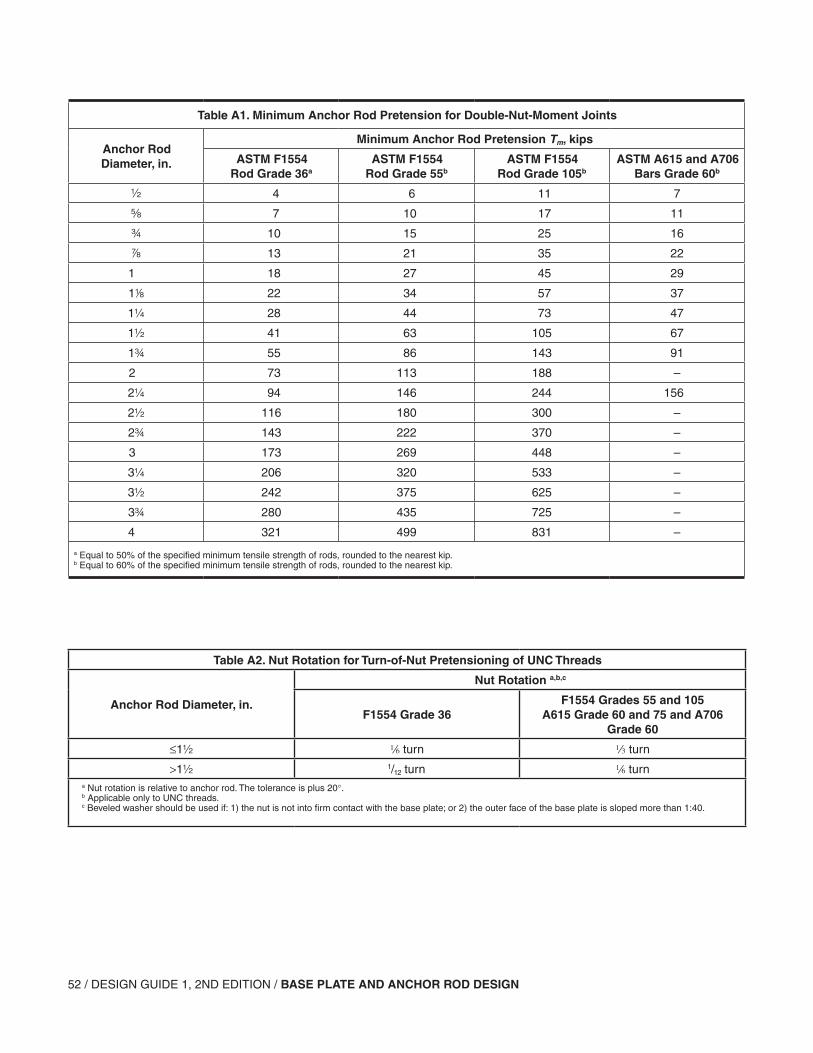
52 / DESIGN GUIDE 1, 2ND EDITION / BASE PLATE AND ANCHOR ROD DESIGN
Table A2. Nut Rotation for Turn-of-Nut Pretensioning of UNC Threads
Anchor Rod Diameter, in.
Nut Rotation a,b,c
F1554 Grade 36F1554 Grades 55 and 105
A615 Grade 60 and 75 and A706 Grade 60
≤1 6 turn 3 turn
>1 111/12 turn 6 turna Nut rotation is relative to anchor rod. The tolerance is plus 20°.b Applicable only to UNC threads.c Beveled washer should be used if: 1) the nut is not into firm contact with the base plate; or 2) the outer face of the base plate is sloped more than 1:40.
Table A1. Minimum Anchor Rod Pretension for Double-Nut-Moment Joints
Anchor Rod Diameter, in.
Minimum Anchor Rod Pretension Tm, kips
ASTM F1554 Rod Grade 36a
ASTM F1554 Rod Grade 55b
ASTM F1554 Rod Grade 105b
ASTM A615 and A706 Bars Grade 60b
4 6 11 7
s 7 10 17 11
w 10 15 25 16
d 13 21 35 22
1 18 27 45 29
18 22 34 57 37
1 28 44 73 47
1 41 63 105 67
1w 55 86 143 91
2 73 113 188 –
2 94 146 244 156
2 116 180 300 –
2w 143 222 370 –
3 173 269 448 –
3 206 320 533 –
3 242 375 625 –
3w 280 435 725 –
4 321 499 831 –
a Equal to 50% of the specified minimum tensile strength of rods, rounded to the nearest kip.b Equal to 60% of the specified minimum tensile strength of rods, rounded to the nearest kip.
DESIGN GUIDE 1, 2ND EDITION / BASE PLATE AND ANCHOR ROD DESIGN / 53
16. Leveling nuts should be tightened to between 20 and 30% of the verification torque following a star pattern.
17. Before further turning the nuts, the reference position of the top nut in the initial condition should be marked on an intersection between flats with a corresponding reference mark on the base plate at each bolt. Top nuts should be turned in increments following a star pattern (using at least two full tightening cycles) to the nut ro-tation specified in Table A2 if UNC threads are used. If 8UN threads are used, the appropriate nut rotation should be shown in the contract documents or speci-fied by the Engineer of Record. After tightening, the nut rotation should be verified.
18. A torque wrench should be used to verify that a torque at least equal to the verification torque is required to additionally tighten the leveling nuts and the top nuts. An inability to achieve this torque means it is likely that the threads have stripped and this must be reported to the Engineer of Record.
19. After at least 48 hours, the torque wrench should again be used to verify that a torque at least equal to 110 per-cent of the verification torque is required to additionally tighten the leveling nuts and the top nuts. For cantile-ver or other nonredundant structures, this verification should be made at least 48 hours after erection of the remainder of the structure and any heavy attachments to the structure.
20. If the joint was designed for Seismic Design Category D or greater according to ASCE 7, or designed for fatigue, the nut should be prevented from loosening unless a maintenance plan is in place to verify at least every four years that a torque equal to at least 110% of the verification torque is required to additionally tighten the leveling nuts and the top nuts.
A2.2 Pretensioned Joints
The installation procedures for pretensioned joints are very similar to the first steps for double-nut-moment joints, except for the inclusion of the sleeve. The sleeve must be cleaned and sealed off to prevent inclusion of debris.
Anchor rods are typically tensioned using a center-hole ram with access to the nut for retightening. The nut is tight-ened down while the tension is maintained on the anchor rod, and the anchor rod tension is released. It is recognized that part of the tension will be lost to relaxation after the tension is released. Since there are many variations of pre-tensioned joints, the Engineer of Record should provide the specific procedures for tightening these joints.
Installation sequence:
1. The assembly of sleeve and anchor rod should be se-cured in its correct position in accordance with the con-tract documents.
2. If a template is used, the hole pattern should be verified by comparing the top template to the base plate to be erected and any deviation between the hole positions outside of the tolerances must be reported to the Engi-neer of Record.
3. The concrete should be placed and cured.
4. If a top template is above the concrete surface, it may be removed no sooner than 24 hours after placing the concrete.
5. The exposed part of the anchor rods should be cleaned with a wire brush or equivalent and lubricated.
6. The opening of the sleeve should be cleaned of debris and sealed off.
7. After removal of the template, if any, the anchor rods should be inspected visually to verify that there is no visible damage to the threads and that their position, elevation, and projected length from the concrete are within the tolerances specified in the contract docu-ments. In the absence of required tolerances, the posi-tion, elevation, and projected length from the concrete should be within the tolerances specified in the AISC Code of Standard Practice for Steel Buildings and Bridges. The nuts should be turned onto the bolts at least one rod diameter past the elevation of the bottom of the base plate and backed off by a worker using an ordinary wrench without a cheater bar. Any damage resulting in unusual effort to turn the nut should be reported to the Engineer of Record.
8. The base plate and attached structural element, or piece of equipment or machinery, should be placed.
9. Washers should be placed.
10. If threads of anchor rods were lubricated more than 24 hours before placing the nut or have been wet since they were lubricated, the exposed threads of the anchor rod should be relubricated. Nuts should be cleaned and the threads and bearing surfaces lubricated.
11. The pretension and pretensioning method should be as specified in the contract documents, along with the pro-cedures and requirements for an installation verification test, if necessary.
54 / DESIGN GUIDE 1, 2ND EDITION / BASE PLATE AND ANCHOR ROD DESIGN
A3. Inspection and Maintenance After Installation
Regular inspection and maintenance should be conducted for joints that are designed for the fatigue. All joints designed for Seismic Design Category D or greater, according to ASCE 7, should also be inspected and maintained as follows after a significant seismic event.
1. Anchor rod appearance—Draw a diagram of the anchor rod pattern and number in a clockwise pattern. Check each anchor rod for corrosion, gouges, or cracks. Suspected cracks may be more closely examined using the dye-penetrant technique. If there is heavy corrosion near the interface with the concrete, there may be more severe corrosion hidden below the concrete where the pocket around the anchor rod stays wet. Verify that all the anchor rods have top nuts with washers. Lock washers should not be used. Galvanized nuts or wash-ers should not be used with unpainted weathering steel. Check for inadequately sized washers for oversize holes. If there is no grout pad, verify that all the anchor rods have leveling nuts with washers. Check for loose nuts, gouges, thread damage, or corrosion. Note any anchor rods that are significantly misaligned or bent to fit in the base plate hole. Note any anchor rods that are not flush with or projecting past the nut. If the anchor rod is not projecting past the nut, measure the distance from the top of the nut to the top of the anchor rod.
2. Sounding the anchor rods—Anchor rods may be struck by a hammer (a large ball peen hammer is sug-gested) to detect broken bolts. Strike the side of the top nut and the top of the rod. Good tight anchor rods will all have a similar ring. Broken or loose anchor rods will have a distinctly different and duller sound.
3. Tightness of anchor rod nuts—It should be verified that the top nuts still have a sound tack weld (at the top of the top nut only) or a jam nut. Tack welds to the washer or the base plate are undesirable and should be reported. If one of these is not used to prevent loosening of the nut, the tightness should be verified by applying a torque equal to 110% of the torque computed using the torque equation, in accordance with step 20 of the installation procedure for double-nut joints.
If one nut in a joint is loose (the tack weld is fractured or the nut does not reach the required torque), it should be unscrewed, cleaned, inspected for possible thread stripping, lubricated, placed and brought to the initial condition, and retightened to the pretension specified in Table A1 using the turn-of-nut method.
If more than one nut in a joint is loose, the entire joint should be disassembled, all the anchor rods visually inspected, and the joint reassembled with new nuts. If more than one nut is loose, the joint may have been poorly installed or fatigue problems may exist. A close following of the performance of the joint should be made.
4. Ultrasonic test of anchor rods—An ultrasonic test of anchor rods need be performed only if
• Welded repairs have been made.
• Similar structures subject to similar loading have had fatigue problems.
• Anchor rods were not adequately designed for fatigue in accordance with this Specification.
The inspection should include at least
a. Verification that the joint is kept free of debris, water and vegetation.
b. Verification that there is not severe corrosion, gouges, or cracks.
c. Verification that the grout and concrete in the vi-cinity of the anchor rods is in good condition.
d. A hammer sound test of anchor rods.
e. Verification of the tightness of nuts. It should be verified that the nuts still have a jam nut or other locking device or the tightness should be verified by applying 110% of the verification torque.
f. Retightening of anchor rods, if needed.
If similar structures subject to similar loading have had anchor rod fatigue cracking problems, an ultrasonic test of anchor rods should be performed. The top of the rod or ex-tension should be ground flush and the ultrasonic test and its interpretation should be in accordance with a procedure approved by a qualified engineer.
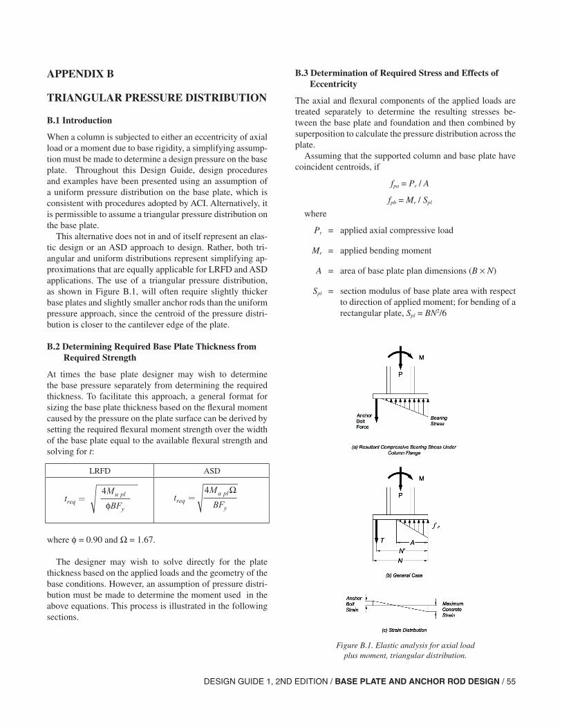
DESIGN GUIDE 1, 2ND EDITION / BASE PLATE AND ANCHOR ROD DESIGN / 55
APPENDIX B
TRIANGULAR PRESSURE DISTRIBUTION
B.1 Introduction
When a column is subjected to either an eccentricity of axial load or a moment due to base rigidity, a simplifying assump-tion must be made to determine a design pressure on the base plate. Throughout this Design Guide, design procedures and examples have been presented using an assumption of a uniform pressure distribution on the base plate, which is consistent with procedures adopted by ACI. Alternatively, it is permissible to assume a triangular pressure distribution on the base plate.
This alternative does not in and of itself represent an elas-tic design or an ASD approach to design. Rather, both tri-angular and uniform distributions represent simplifying ap-proximations that are equally applicable for LRFD and ASD applications. The use of a triangular pressure distribution, as shown in Figure B.1, will often require slightly thicker base plates and slightly smaller anchor rods than the uniform pressure approach, since the centroid of the pressure distri-bution is closer to the cantilever edge of the plate.
B.2 Determining Required Base Plate Thickness from Required Strength
At times the base plate designer may wish to determine the base pressure separately from determining the required thickness. To facilitate this approach, a general format for sizing the base plate thickness based on the flexural moment caused by the pressure on the plate surface can be derived by setting the required flexural moment strength over the width of the base plate equal to the available flexural strength and solving for t:
where φ = 0.90 and Ω = 1.67.
The designer may wish to solve directly for the plate thickness based on the applied loads and the geometry of the base conditions. However, an assumption of pressure distri-bution must be made to determine the moment used in the above equations. This process is illustrated in the following sections.
B.3 Determination of Required Stress and Effects of Eccentricity
The axial and flexural components of the applied loads are treated separately to determine the resulting stresses be-tween the base plate and foundation and then combined by superposition to calculate the pressure distribution across the plate.
Assuming that the supported column and base plate have coincident centroids, if
fpa = Pr / A
fpb = Mr / Spl
where
Pr = applied axial compressive load
Mr = applied bending moment
A = area of base plate plan dimensions (B × N)
Spl = section modulus of base plate area with respect to direction of applied moment; for bending of a rectangular plate, Spl = BN2/6
Figure B.1. Elastic analysis for axial load plus moment, triangular distribution.
t M
BFrequ pl
y
=
4
φ
LRFD ASD
tM
BFreqa pl
y
=4 Ω
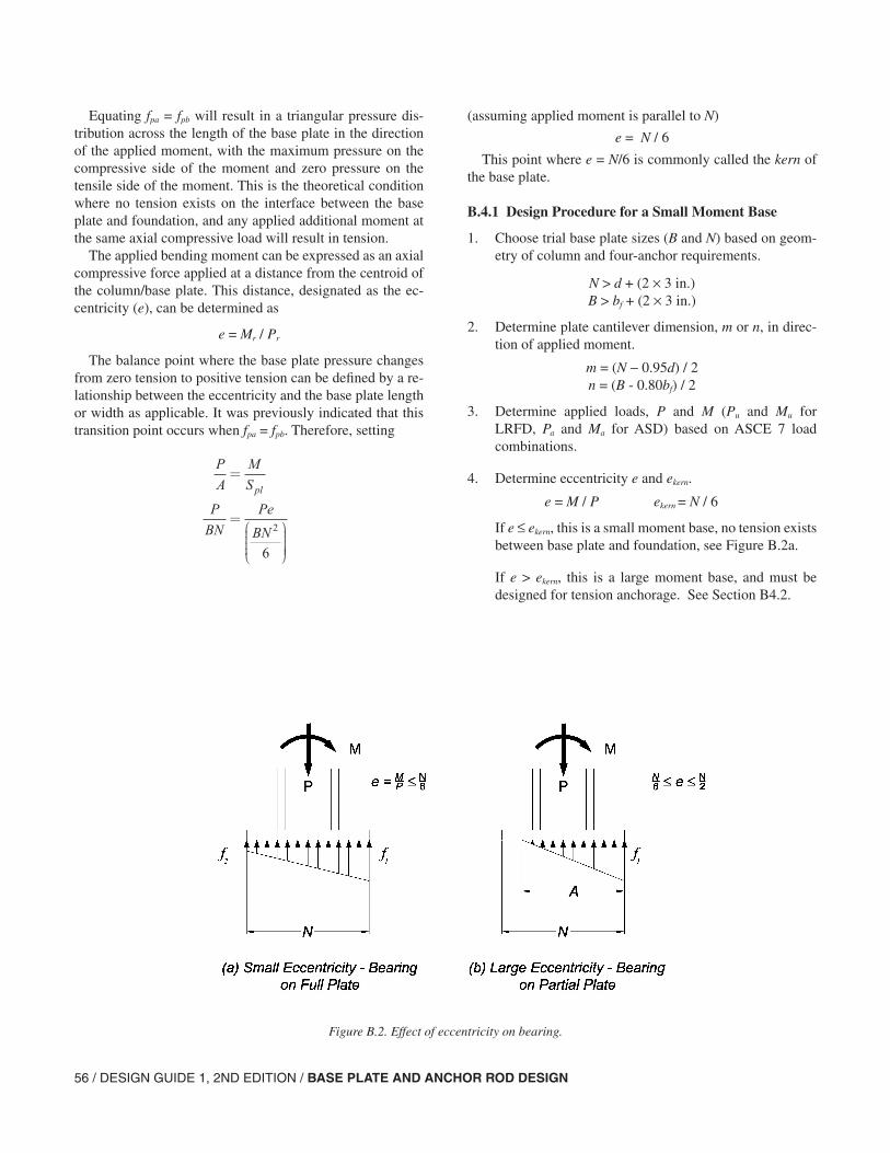
56 / DESIGN GUIDE 1, 2ND EDITION / BASE PLATE AND ANCHOR ROD DESIGN
Equating fpa = fpb will result in a triangular pressure dis-tribution across the length of the base plate in the direction of the applied moment, with the maximum pressure on the compressive side of the moment and zero pressure on the tensile side of the moment. This is the theoretical condition where no tension exists on the interface between the base plate and foundation, and any applied additional moment at the same axial compressive load will result in tension.
The applied bending moment can be expressed as an axial compressive force applied at a distance from the centroid of the column/base plate. This distance, designated as the ec-centricity (e), can be determined as
e = Mr / Pr
The balance point where the base plate pressure changes from zero tension to positive tension can be defined by a re-lationship between the eccentricity and the base plate length or width as applicable. It was previously indicated that this transition point occurs when fpa = fpb. Therefore, setting
P
A
M
S
P
BN
Pe
BN
pl
=
=
2
6
(assuming applied moment is parallel to N)
e = N / 6
This point where e = N/6 is commonly called the kern of the base plate.
B.4.1 Design Procedure for a Small Moment Base
1. Choose trial base plate sizes (B and N) based on geom-etry of column and four-anchor requirements.
N > d + (2 × 3 in.)B > bf + (2 × 3 in.)
2. Determine plate cantilever dimension, m or n, in direc-tion of applied moment.
m = (N − 0.95d) / 2n = (B - 0.80bf) / 2
3. Determine applied loads, P and M (Pu and Mu for LRFD, Pa and Ma for ASD) based on ASCE 7 load combinations.
4. Determine eccentricity e and ekern.
e = M / P ekern = N / 6
If e ≤ ekern, this is a small moment base, no tension exists between base plate and foundation, see Figure B.2a.
If e > ekern, this is a large moment base, and must be designed for tension anchorage. See Section B4.2.
Figure B.2. Effect of eccentricity on bearing.
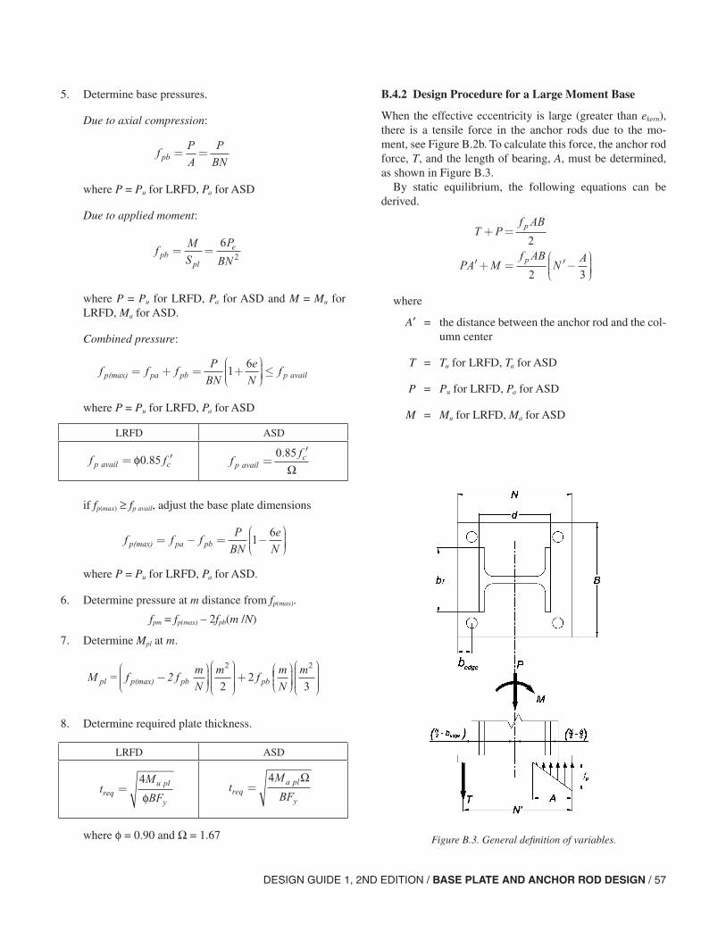
DESIGN GUIDE 1, 2ND EDITION / BASE PLATE AND ANCHOR ROD DESIGN / 57
LRFD ASD
5. Determine base pressures.
Due to axial compression:
where P = Pu for LRFD, Pa for ASD
Due to applied moment:
where P = Pu for LRFD, Pa for ASD and M = Mu for LRFD, Ma for ASD.
Combined pressure:
where P = Pu for LRFD, Pa for ASD
if fp(max) ≥ fp avail, adjust the base plate dimensions
where P = Pu for LRFD, Pa for ASD.
6. Determine pressure at m distance from fp(max).
fpm = fp(max) – 2fpb(m /N)
7. Determine Mpl at m.
8. Determine required plate thickness.
where φ = 0.90 and Ω = 1.67
LRFD ASD
fP
A
P
BN pb = =
fM
S
P
BNpb
pl
e= =6
2
f f fP
BN
e
Nfp pa pb p avail(max) = + = +
≤1
6
f fp avail c = ′φ0 85.
f f fP
BN
e
Np pa pb(max) = − = −
1
6
B.4.2 Design Procedure for a Large Moment Base
When the effective eccentricity is large (greater than ekern), there is a tensile force in the anchor rods due to the mo-ment, see Figure B.2b. To calculate this force, the anchor rod force, T, and the length of bearing, A, must be determined, as shown in Figure B.3.
By static equilibrium, the following equations can be derived.
where
A′ = the distance between the anchor rod and the col-umn center
T = Tu for LRFD, Ta for ASD
P = Pu for LRFD, Pa for ASD
M = Mu for LRFD, Ma for ASD
M f fm
N
mf
m
Npl p(max) pb pb= 2 −
+
2
22
m2
3
tM
BFrequ pl
y
=4
φ
Figure B.3. General definition of variables.
T P f AB
PA Mf AB
NA
p
p
+ =
′+ = ′−
2
2 3
ff
p availc
=′0 85.
Ω
tM
BFreqa pl
y
=4 Ω
58 / DESIGN GUIDE 1, 2ND EDITION / BASE PLATE AND ANCHOR ROD DESIGN
By summing the moments about the resulting bolt force and solving as a quadratic function, the following expression can be determined for calculating the bearing distance, A:
where
f ′ = fpBN′/2
P = Pu for LRFD, Pa for ASD
M = Mu for LRFD, Ma for ASD
The resulting tensile force in the anchor rods is then
where T = Tu for LRFD, Ta for ASD, and P = Pu for LRFD, Pa for ASD.
The design procedure is as follows:
1. Determine the available bearing strength, φPp or Pp /Ω with
2. Choose trial base plate sizes (B and N) based on geom-etry of column and the four-anchor requirement.
3. Determine the length of bearing, A, equal to the small-est positive value from the equation in Section B.4.2. If the value is reasonable, go on to the next step. If it is close to the value of N′, the solution is not practical since this implies that bearing exists in the vicinity of the anchor rod. If this were so, the anchor rod could not develop its full tensile strength. It is then necessary to return to Step 2 and choose another, larger plate size.
4. Determine the resultant anchor bolt force, T, from the above equation. If it is reasonable, go to the next step. Otherwise return to Step 2.
5. Determine the required moment strength per inch of plate as the greater of the moment due to the pressure and the moment due to tension in the anchor rods. Each is to be determined at the appropriate critical section.
A
f ff B
PA M
f B
p
p=
′± ′ −
′+2 46
3
( )
Tf AB
Pp= −2
P f A A A f Ap c c= ′ ≤ ′
= =
0 85 1 7
0 90 1 67
1 2 1 1. / .
. .φ Ω
6. Determine the plate thickness based on the required flexural strength per inch of plate:
B.5 Example: Small Moment Base Plate Design, Triangular Pressure Distribution Approach
Design a base plate for axial dead and live loads equal to 100 and 160 kips, respectively, and moments from the dead and live loads equal to 250 and 400 kip-in., respectively. Bending is about the strong axis for the wide flange column W12×96 with d = 12.7 in. and bf = 12.2 in. The ratio of the concrete to base plate area is unity; Fy of the base plate is 36 ksi and fc′ of the concrete is 4 ksi.
1. Choose trial base plate sizes (B and N) based on geom-etry of column and 4-anchor requirements.
N > d + (2 × 3.0 in.) = 12.7 + 6 =18.7 in.B > bf + (2 × 3.0 in.) = 12.2 + 6 = 18.2 in.
Try N = 19 in., B = 19 in.
2. Determine plate cantilever dimension, m or n, in direc-tion of applied moment.
3. Determine applied loads, P and M, based on ASD or LRFD load combinations.
4. Determine eccentricity e and ekern.
LRFD ASD
tM
Fpu pl
y
=4
φt
M
Fpa pl
y
=4 Ω
mN d
nB b
in.
in.
=−
=−
=
=−
( . ) . . ( . ).
.
0 95
2
19 0 0 95 12 7
23 47
0 80 ff
2
19 0 80 12 2
2
in. = 4.62 in.
(Not in direction of ap
=− . ( . )
pplied moment)
LRFD ASD
Pu = 1.2(100) + 1.6(160) = 376 kips
Mu = 1.2(250) + 1.6(400) = 940 kip-in.
Pa = 100 + 160 = 260 kips
Ma = 250 + 400 = 650 kip-in.
LRFD ASD
eM
Puu
u
= = =940
3762 5. in. e
M
Pau
u
= = =650
2602 5. in.
DESIGN GUIDE 1, 2ND EDITION / BASE PLATE AND ANCHOR ROD DESIGN / 59
6. Determine pressure at critical bending plane [m distance from fp(max)].
7. Determine Mpl for bending about critical planes at m and n.
Bending of a 1-in.-wide strip of plate about a plane at m, in the direction of applied moment:
Bending about a plane at n, perpendicular to applied moment. For the case of axial loads plus small mo-ments, the procedure shown below can be used (using the axial load only). For axial loads plus large moments, a more refined analysis is required.
The critical moment is the larger of Mpl about m and n critical planes.
Thus, e = 2.5 in. < ekern = 3.17 in., this is a small moment base, no tension exists between base plate and founda-tion.
5. Determine base pressures for a 1-in. strip of plate.
Due to axial compression:
Due to applied moment:
Combined pressure:
eN
nker.
.= = =6
19 0
63 17 in.
fP
A
P
BNp ax( ) = =
LRFD ASD
fP
BNp axu
( )
.
kips
in. in. ksi
=
=×
=376
19 191 04
fP
BNp(ax)a =
kips
in. in. ksi=
×=
260
19 190 720.
fM
S
Pe
BNp b
pl( ) = =
62
LRFD ASD
f fP e
BNp(ax) p
u =
kips in.
in
(bu) =
=
6
6 376 2 50
19
2
( )( . )
.. in.
kips/in.
×( )=
19
0 822
2
.
f fP e
BNp ax p ba
a( ) ( )
( )( . )
= =
=
kips in.
in.
6
6 260 2 50
19
2
××( )=
19
0 569
2 in.
kips/in..
LRFD ASD
f f f
f
pu p ax u p b u
p
(max) =
= +=
+
kips/in.
( ) ( )
. .
.
1 042 0 822
1 86
uu p ax u p b uf f(min) =
kips/in.
( ) ( )
. .
.
+
= −=
1 042 0 822
0 220
+
kips/in.
f f f
f
pa p ax u p b u
pa
(max)
(
=
= +=
( ) ( )
. .
.
0 720 0 569
1 29
mmin) =
= −=
f fp ax u p b u( ) ( )
. .
.
+
kips/in.
0 720 0 569
0 151
LRFD ASD
f f f m
Npu m pu p b u( ) ( )
.( . )( .
= −
= −
(max) 2
1 862 0 822 3 47 iin.
in. kips/in.
)
.19
1 56=
f f f m
Npa m pa p b a( ) ( )
.( . )( .
= −
= −
(max) 2
1 292 0 569 3 47 inn.
in. kips/in.
)
.19
1 08=
LRFD ASD
M fm
f fm
u pl pu m
pu pu m
=( )
+ −( )
( )
( )
2
2
2
3(max)
=( )
+ −
M
u pl 1 563 47
2
1 86 1 56
2
.( . )
. .
kips/in. in.
kipps/in. in.
kip-in.
( )
=
( . )
.
3 47
310 6
2
M fm
f fm
a pl pa m
pa pa m
=( )
+ −( )
( )
( )
2
2
2
3(max)
=( )
+ −
M
u pl 1 083 47
2
1 29 1 08
2
.( . )
. .
kips/in. in.
kiips/in. in.
kip-in.
( )
=
( . )
.
3 47
37 34
2
LRFD ASD
M fn
u pl p ax u=
=
( )
.( . )
2
2
2
1 044 62
2 kips/in.
in.
==11 1. kip-in./in.
M fn
a pl p ax a=
=
( )
.( . )
2
2
2
0 7204 62
kips/in. in.
227 68= . kip-in./in.
LRFD ASD
Mu crit = 11.1 kip-in./in. Ma crit = 7.68 kip-in./in.
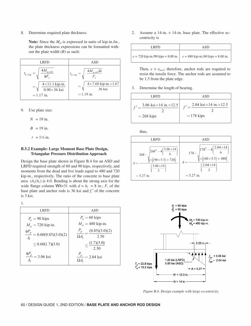
60 / DESIGN GUIDE 1, 2ND EDITION / BASE PLATE AND ANCHOR ROD DESIGN
2. Assume a 14-in. × 14-in. base plate. The effective ec-centricity is
Then, e > ekern; therefore, anchor rods are required to resist the tensile force. The anchor rods are assumed to be 1.5 from the plate edge.
3. Determine the length of bearing.
thus,
8. Determine required plate thickness:
Note: Since the Mpl is expressed in units of kip-in./in., the plate thickness expressions can be formatted with-out the plate width (B) as such:
9. Use plate size:
N = 19 in.
B = 19 in.
t = 14 in.
B.5.2 Example: Large Moment Base Plate Design, Triangular Pressure Distribution Approach
Design the base plate shown in Figure B.4 for an ASD and LRFD required strength of 60 and 90 kips, respectively, and moments from the dead and live loads equal to 480 and 720 kip-in., respectively. The ratio of the concrete to base plate area (A2/A1) is 4.0. Bending is about the strong axis for the wide flange column W8×31 with d = bf = 8 in.; Fy of the base plate and anchor rods is 36 ksi and fc′ of the concrete is 3 ksi.
1.
LRFD ASD
tM
Fu requ crit
y
kip-in.
ksi in.
=
=××
=
4
4 11 1
0 90 361 17
φ
.
..
tM
Fa reqa crit
y
kip-in.
ksi in.
=
=× ×
=
4
4 7 68 1 67
361 19
Ω
. .
.
LRFD ASD
P
M
P
A
u
u
p
=
=
=
≤
90
720
0 60 0 85 3 0 2
0 60 1 71
kips
kip-in.
φ. ( . )( . )( )
. ( . )(( . )3 0
P
M
P
A
a
a
p
=
=
=
≤
60
480
0 85 3 0 2
2 50
1 7 3 01
kips
kip-in.
Ω( . )( . )( )
.
( . )( . ))
.
.
2 50
2 041
P
Ap
Ω= ksi
LRFD ASD
e = 720 kip-in./90 kips = 8.00 in. e = 480 kip-in./60 kips = 8.00 in.
Figure B.4. Design example with large eccentricity.
LRFD ASD
′ =× ×
=
f3 06 14 12 5
2268
. . ksi in. in.
kips
′ =× ×
=
f 2 04 14 12 5
2178
. . ksi in. in.
kips
LRFD ASD
A=
−−
×
× ×( )+
×
268268 4
3 06 146
90 5 5 720
3 06 143
2 .
.
.
= in.5 27.
A=
−−
×
× ×( )+
×
178178 4
2 04 146
60 5 5 480
2 04 143
2 .
.
.
= in.5 27.
φP
Ap
1
3 06= . ksi
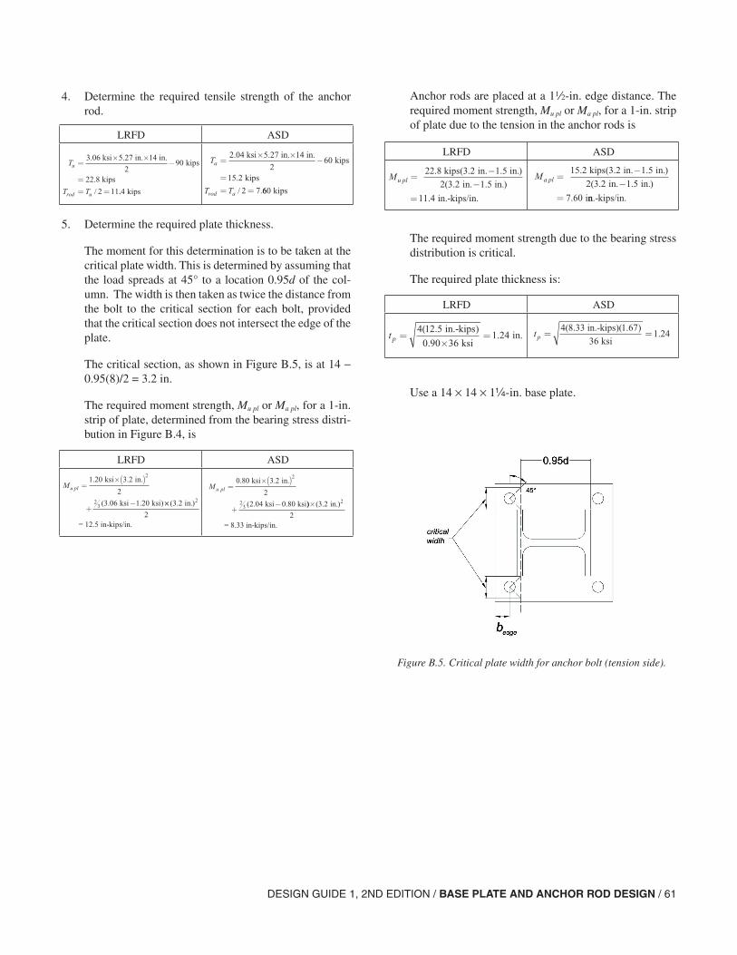
DESIGN GUIDE 1, 2ND EDITION / BASE PLATE AND ANCHOR ROD DESIGN / 61
Anchor rods are placed at a 12-in. edge distance. The required moment strength, Mu pl or Ma pl, for a 1-in. strip of plate due to the tension in the anchor rods is
The required moment strength due to the bearing stress distribution is critical.
The required plate thickness is:
Use a 14 × 14 × 1-in. base plate.
4. Determine the required tensile strength of the anchor rod.
5. Determine the required plate thickness.
The moment for this determination is to be taken at the critical plate width. This is determined by assuming that the load spreads at 45° to a location 0.95d of the col-umn. The width is then taken as twice the distance from the bolt to the critical section for each bolt, provided that the critical section does not intersect the edge of the plate.
The critical section, as shown in Figure B.5, is at 14 − 0.95(8)/2 = 3.2 in.
The required moment strength, Mu pl or Ma pl, for a 1-in. strip of plate, determined from the bearing stress distri-bution in Figure B.4, is
LRFD ASD
T
T T
u
rod u
=× ×
−
== =
3.06 ksi 5.27 in. 14 in. kips
kips2
90
22 8
2 11
.
/ ..4 kips
T
T T
a
rod a
=× ×
−
== =
2.04 ksi 5.27 in. 14 in. kips
kips2
60
15 2
2 7
.
/ .660 kips
LRFD ASD
Mu pl =×( )
+−
1 20 3 2
2
3 06 1 20
2
23
. .
( . . )
ksi in.
ksi ksi ××( . )3 2
2
2 in.
= 12.5 in-kips/in.
Ma pl
ksi in.
ksi ksi
=×( )
+−
0 80 3 2
2
2 04 0 80
2
23
. .
( . . )) ( . )× 3 2
2
2 in.
= 8.33 in-kips/in.
LRFD ASD
M u pl =−
−
kips in. in.
in in.
22 8 3 2 1 5
2 3 2 1 5
. ( . . )
( . . . )
in.-kips/in.=11 4.
M a pl =−
−=
kips in. in.
in. in.
i
15 2 3 2 1 5
2 3 2 1 5
7 60
. ( . . )
( . . )
. nn.-kips/in.
LRFD ASD
t p = ×=
4 12 5
0 90 361 24
( . )
..
in.-kips
ksi in. t p = =
4 8 33 1 67
361 24
( . )( . ).
in.-kips
ksi
Figure B.5. Critical plate width for anchor bolt (tension side).

62 / DESIGN GUIDE 1, 2ND EDITION / BASE PLATE AND ANCHOR ROD DESIGN