Embed Size (px)
Citation preview
Keywords— Railway bridges, base isolation, steel dampers, lead rubber bearings, passive control.
Abstract— The seismic vulnerability assessment of existing and
new lifelines, especially transportation systems, either highways or railways, is becoming of paramount importance in resilient social communities. The structural performance analysis of typical existing bridges for high speed railway is however not an easy task to accomplish. Additionally, the seismic assessment of such as-built bridges tend to emphasize the high vulnerability of the structural systems. In the present analytical work, the earthquake response analysis of typical existing bridges for high speed railway was carried out through linear and nonlinear dynamic analyses using refined finite element three-dimensional lumped-plasticity models and multiple component ground motions. The seismic vulnerability of such bridges was assessed through local and global response quantities. The retrofitting scheme adopted to augment the earthquake performance of the sample bridge structures is the base isolation system comprising either lead rubber bearings or steel dampers. The present study investigates and compares the response of such isolation devices. The outcomes of the numerical analyses proved that the use of base isolation systems lowered significantly the seismic demand, especially on the bridge piers and the foundation systems. Hysteretic metallic devices were found more suitable for the seismic isolation of railway bridges. Additionally, the need to comply with the serviceability requirements is found to be more stringent for the base isolation system in the design of retrofitting schemes for railway bridges than the fulfillment of the ultimate limit state. Further work is ongoing to account for the nonlinear modeling of the rail on the global response of base isolated railway bridges under multiple earthquake components.
I. INTRODUCTION UMEROUS existing structures and infrastructures in
earthquake-prone regions world-wide were built without seismic details; hence they possess high seismic vulnerability. Modern communities should be resilient to minimize the earthquake-induced losses and provide rapid response in the aftermath of extreme natural events; thus lifelines should be assessed reliably and retrofitted adequately, where necessary. Highway and railway infrastructures are vital transportation networks. Numerous earthquakes have demonstrated that they can experience significant structural and non-structural damage. Surveys carried out in the aftermath of moderate-to-major seismic ground motions emphasized that damage may also occur in the rail tracks. Permanent lateral displacements
L. Di Sarno is with University of Sannio, Department of Engineering,
82100 Benevento, Italy (corresponding author to provide phone: +39-0824305565; fax: +39-0824325246; e-mail: [email protected]).
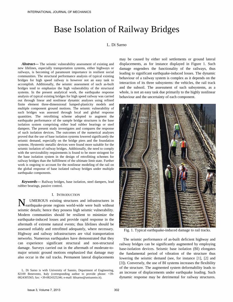
may be caused by either soil settlements or ground lateral displacements, as for instance displayed in Figure 1. Such damage engenders the functionality of the railways, thus leading to significant earthquake-induced losses. The dynamic behaviour of a railway system is complex as it depends on the interaction of its three subsystems: the vehicles, the rail track and the subsoil. The assessment of such subsystems, as a whole, is not an easy task due primarily to the highly nonlinear behaviour and the uncertainty of each component.
Fig. 1. Typical earthquake-induced damage to rail tracks. The seismic performance of as-built deficient highway and
railway bridges can be significantly augmented by employing base-isolation devices. Seismic base isolation (BI) elongates the fundamental period of vibration of the structure thus lowering the seismic demand (see, for instance [1], [2] and [3]). Conversely, the use of BI systems increases the flexibility of the structure. The augmented system deformability leads to an increase of displacements under earthquake loading. Such dynamic response may be detrimental for railway structures.
Base Isolation of Railway Bridges L. Di Sarno
N
INTERNATIONAL JOURNAL OF MECHANICS
Issue 3, Volume 7, 2013 302
The rail, i.e. a long steel welded component, does not allow large (absolute and relative) displacements between the decks and between the decks and abutments, especially along the transversal direction, to fulfill the serviceability requirements. As a consequence, base isolation has been employed for the seismic design and retrofitting of highway bridges worldwide (e.g. [4] among many others), but the applications for railway structures are yet scarce.
The present analytical study investigates the viability of using BI systems to retrofit existing seismically vulnerable railway bridges. A sample structures is thus selected as a case study. Comprehensive elastic and inelastic response history analyses are carried out to estimate the structural response of the railway bridge retrofitted with isolation devices. The selected seismic retrofitting strategy is aimed at guaranteeing the elastic response of bridge piers and deck at life safety limit state (ultimate limit state, ULS) and to minimize the demand on the foundation piles. Different isolation systems were considered and the structural performance of the retrofitted sample bridge checked with respect to serviceability and ultimate limit states. The serviceability was warranted by considering in the design of the base isolators the breakage conditions of the high-speed train.
The outcomes of the present study demonstrate the cost-effectiveness of the use of isolation devices to seismically protect existent high-speed railway bridge systems which exhibit moderate-to-high vulnerability. A discussion of the optimal isolator type for railway bridges is also provided hereafter.
II. THE CASE STUDY RAILWAY BRIDGE The sample bridge structure is a branch of the high speed
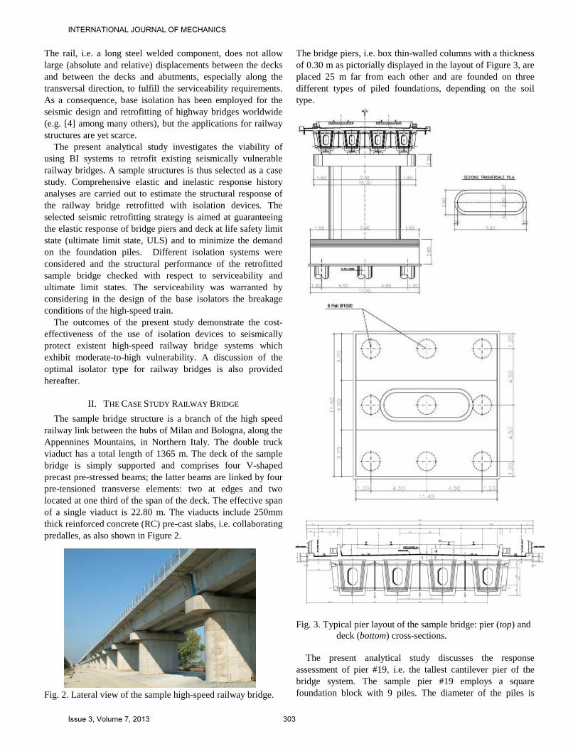
railway link between the hubs of Milan and Bologna, along the Appennines Mountains, in Northern Italy. The double truck viaduct has a total length of 1365 m. The deck of the sample bridge is simply supported and comprises four V-shaped precast pre-stressed beams; the latter beams are linked by four pre-tensioned transverse elements: two at edges and two located at one third of the span of the deck. The effective span of a single viaduct is 22.80 m. The viaducts include 250mm thick reinforced concrete (RC) pre-cast slabs, i.e. collaborating predalles, as also shown in Figure 2.
Fig. 2. Lateral view of the sample high-speed railway bridge.
The bridge piers, i.e. box thin-walled columns with a thickness of 0.30 m as pictorially displayed in the layout of Figure 3, are placed 25 m far from each other and are founded on three different types of piled foundations, depending on the soil type.
Fig. 3. Typical pier layout of the sample bridge: pier (top) and
deck (bottom) cross-sections.
The present analytical study discusses the response assessment of pier #19, i.e. the tallest cantilever pier of the bridge system. The sample pier #19 employs a square foundation block with 9 piles. The diameter of the piles is
INTERNATIONAL JOURNAL OF MECHANICS
Issue 3, Volume 7, 2013 303
φ1500 mm; their length is 21 m. The square footing has a thickness varying between 1.80 and 2.60 m; the width is 11.4 m. The soil type is a typical mix comprising gravel and sands. The water tables has a depth of about 70m.
III. THE FINITE ELEMENT MODEL A refined finite element three dimensional model,
implemented in the computer program SAP2000 [5] was employed to carry out comprehensive linear and non linear dynamic analyses. The model incorporates also the seismic soil interaction (SSI).
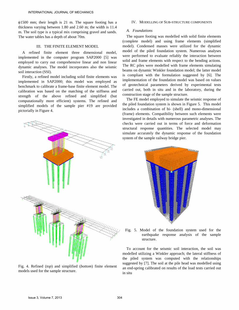
Firstly, a refined model including solid finite elements was implemented in SAP2000; this model was employed as benchmark to calibrate a frame-base finite element model. The calibration was based on the matching of the stiffness and strength of the above refined and simplified (but computationally more efficient) systems. The refined and simplified models of the sample pier #19 are provided pictorially in Figure 4.
Fig. 4. Refined (top) and simplified (bottom) finite element models used for the sample structure.
IV. MODELLING OF SUB-STRUCTURE COMPONENTS
A. Foundations The square footing was modelled with solid finite elements
(complete model) and using frame elements (simplified model). Condensed masses were utilized for the dynamic model of the piled foundation system. Numerous analyses were performed to evaluate reliably the interaction between solid and frame elements with respect to the bending actions. The RC piles were modelled with frame elements simulating beams on dynamic Winkler foundation model; the latter model is compliant with the formulation suggested by [6]. The implementation of the foundation model was based on values of geotechnical parameters derived by experimental tests carried out, both in situ and in the laboratory, during the construction stage of the sample structure.
The FE model employed to simulate the seismic response of the piled foundation system is shown in Figure 5. This model includes a combination of bi- (shell) and mono-dimensional (frame) elements. Compatibility between such elements were investigated in details with numerous parametric analyses. The checks were carried out in terms of force and deformation structural response quantities. The selected model may simulate accurately the dynamic response of the foundation system of the sample railway bridge pier.
Fig. 5. Model of the foundation system used for the
earthquake response analysis of the sample structure.
To account for the seismic soil interaction, the soil was
modelled utilizing a Winkler approach; the lateral stiffness of the piled system was computed with the relationships suggested by [7]. The soil at the pile head was modelled using an end-spring calibrated on results of the load tests carried out in situ
INTERNATIONAL JOURNAL OF MECHANICS
Issue 3, Volume 7, 2013 304
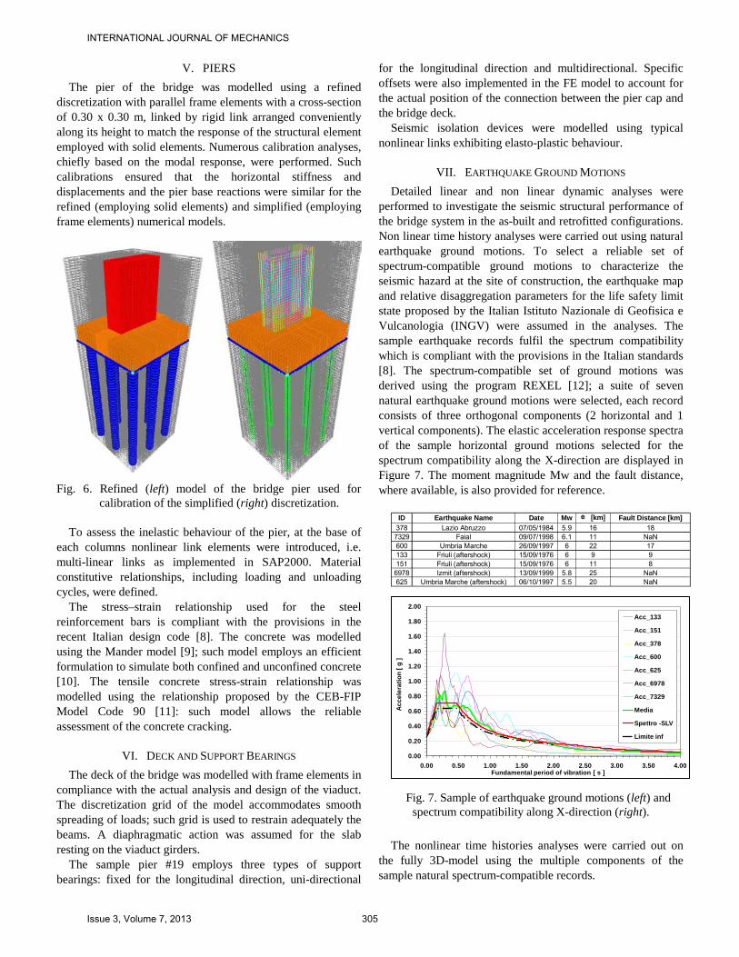
V. PIERS The pier of the bridge was modelled using a refined
discretization with parallel frame elements with a cross-section of 0.30 x 0.30 m, linked by rigid link arranged conveniently along its height to match the response of the structural element employed with solid elements. Numerous calibration analyses, chiefly based on the modal response, were performed. Such calibrations ensured that the horizontal stiffness and displacements and the pier base reactions were similar for the refined (employing solid elements) and simplified (employing frame elements) numerical models.
Fig. 6. Refined (left) model of the bridge pier used for
calibration of the simplified (right) discretization. To assess the inelastic behaviour of the pier, at the base of
each columns nonlinear link elements were introduced, i.e. multi-linear links as implemented in SAP2000. Material constitutive relationships, including loading and unloading cycles, were defined.
The stress–strain relationship used for the steel reinforcement bars is compliant with the provisions in the recent Italian design code [8]. The concrete was modelled using the Mander model [9]; such model employs an efficient formulation to simulate both confined and unconfined concrete [10]. The tensile concrete stress-strain relationship was modelled using the relationship proposed by the CEB-FIP Model Code 90 [11]: such model allows the reliable assessment of the concrete cracking.
VI. DECK AND SUPPORT BEARINGS The deck of the bridge was modelled with frame elements in
compliance with the actual analysis and design of the viaduct. The discretization grid of the model accommodates smooth spreading of loads; such grid is used to restrain adequately the beams. A diaphragmatic action was assumed for the slab resting on the viaduct girders.
The sample pier #19 employs three types of support bearings: fixed for the longitudinal direction, uni-directional
for the longitudinal direction and multidirectional. Specific offsets were also implemented in the FE model to account for the actual position of the connection between the pier cap and the bridge deck.
Seismic isolation devices were modelled using typical nonlinear links exhibiting elasto-plastic behaviour.
VII. EARTHQUAKE GROUND MOTIONS Detailed linear and non linear dynamic analyses were
performed to investigate the seismic structural performance of the bridge system in the as-built and retrofitted configurations. Non linear time history analyses were carried out using natural earthquake ground motions. To select a reliable set of spectrum-compatible ground motions to characterize the seismic hazard at the site of construction, the earthquake map and relative disaggregation parameters for the life safety limit state proposed by the Italian Istituto Nazionale di Geofisica e Vulcanologia (INGV) were assumed in the analyses. The sample earthquake records fulfil the spectrum compatibility which is compliant with the provisions in the Italian standards [8]. The spectrum-compatible set of ground motions was derived using the program REXEL [12]; a suite of seven natural earthquake ground motions were selected, each record consists of three orthogonal components (2 horizontal and 1 vertical components). The elastic acceleration response spectra of the sample horizontal ground motions selected for the spectrum compatibility along the X-direction are displayed in Figure 7. The moment magnitude Mw and the fault distance, where available, is also provided for reference.
ID Earthquake Name Date Mw e [km] Fault Distance [km]
378 Lazio Abruzzo 07/05/1984 5.9 16 187329 Faial 09/07/1998 6.1 11 NaN600 Umbria Marche 26/09/1997 6 22 17133 Friuli (aftershock) 15/09/1976 6 9 9151 Friuli (aftershock) 15/09/1976 6 11 86978 Izmit (aftershock) 13/09/1999 5.8 25 NaN625 Umbria Marche (aftershock) 06/10/1997 5.5 20 NaN
0.00
0.20
0.40
0.60
0.80
1.00
1.20
1.40
1.60
1.80
2.00
0.00 0.50 1.00 1.50 2.00 2.50 3.00 3.50 4.00
Ac
ce
lera
tio
n [
g ]
Fundamental period of vibration [ s ]
Acc_133
Acc_151
Acc_378
Acc_600
Acc_625
Acc_6978
Acc_7329
Media
Spettro -SLV
Limite inf
Fig. 7. Sample of earthquake ground motions (left) and spectrum compatibility along X-direction (right).
The nonlinear time histories analyses were carried out on
the fully 3D-model using the multiple components of the sample natural spectrum-compatible records.
INTERNATIONAL JOURNAL OF MECHANICS
Issue 3, Volume 7, 2013 305
VIII. ASSESSMENT OF THE BRIDGE WITH SUPPORT BEARINGS The seismic re-assessment of the sample bridge structure
was performed considering the viaduct with railway support bearings. The adopted model is used to re-evaluate the structural response in terms of displacements and actions as well as global and local ductile response of the pier. The re-assessment complies with the new Italian code [8].
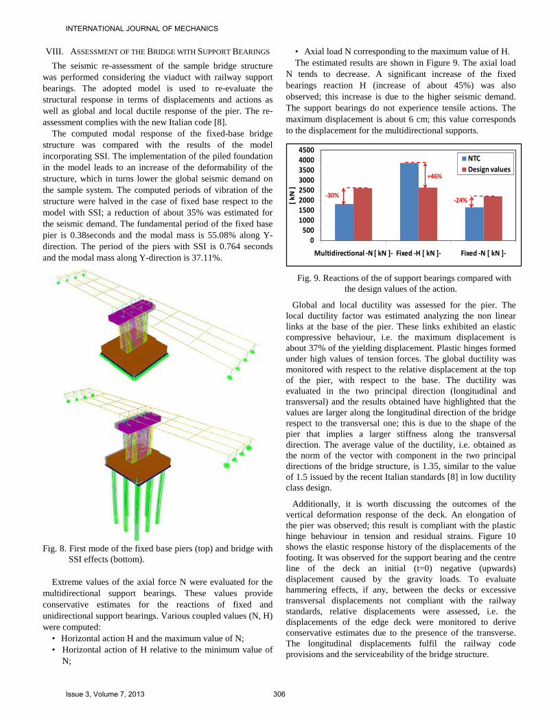
The computed modal response of the fixed-base bridge structure was compared with the results of the model incorporating SSI. The implementation of the piled foundation in the model leads to an increase of the deformability of the structure, which in turns lower the global seismic demand on the sample system. The computed periods of vibration of the structure were halved in the case of fixed base respect to the model with SSI; a reduction of about 35% was estimated for the seismic demand. The fundamental period of the fixed base pier is 0.38seconds and the modal mass is 55.08% along Y-direction. The period of the piers with SSI is 0.764 seconds and the modal mass along Y-direction is 37.11%.
Fig. 8. First mode of the fixed base piers (top) and bridge with
SSI effects (bottom).
Extreme values of the axial force N were evaluated for the multidirectional support bearings. These values provide conservative estimates for the reactions of fixed and unidirectional support bearings. Various coupled values (N, H) were computed:
• Horizontal action H and the maximum value of N; • Horizontal action of H relative to the minimum value of
N;
• Axial load N corresponding to the maximum value of H. The estimated results are shown in Figure 9. The axial load
N tends to decrease. A significant increase of the fixed bearings reaction H (increase of about 45%) was also observed; this increase is due to the higher seismic demand. The support bearings do not experience tensile actions. The maximum displacement is about 6 cm; this value corresponds to the displacement for the multidirectional supports.
0500
10001500200025003000350040004500
Multidirectional -N [ kN ]- Fixed -H [ kN ]- Fixed -N [ kN ]-
[ kN
]
NTCDesign values
-30%
+46%
-24%
Fig. 9. Reactions of the of support bearings compared with
the design values of the action.
Global and local ductility was assessed for the pier. The local ductility factor was estimated analyzing the non linear links at the base of the pier. These links exhibited an elastic compressive behaviour, i.e. the maximum displacement is about 37% of the yielding displacement. Plastic hinges formed under high values of tension forces. The global ductility was monitored with respect to the relative displacement at the top of the pier, with respect to the base. The ductility was evaluated in the two principal direction (longitudinal and transversal) and the results obtained have highlighted that the values are larger along the longitudinal direction of the bridge respect to the transversal one; this is due to the shape of the pier that implies a larger stiffness along the transversal direction. The average value of the ductility, i.e. obtained as the norm of the vector with component in the two principal directions of the bridge structure, is 1.35, similar to the value of 1.5 issued by the recent Italian standards [8] in low ductility class design.
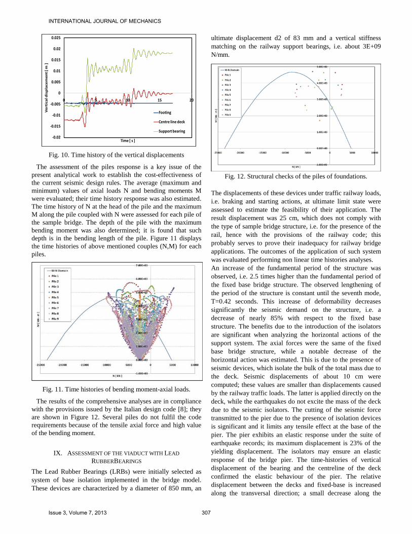
Additionally, it is worth discussing the outcomes of the vertical deformation response of the deck. An elongation of the pier was observed; this result is compliant with the plastic hinge behaviour in tension and residual strains. Figure 10 shows the elastic response history of the displacements of the footing. It was observed for the support bearing and the centre line of the deck an initial (t=0) negative (upwards) displacement caused by the gravity loads. To evaluate hammering effects, if any, between the decks or excessive transversal displacements not compliant with the railway standards, relative displacements were assessed, i.e. the displacements of the edge deck were monitored to derive conservative estimates due to the presence of the transverse. The longitudinal displacements fulfil the railway code provisions and the serviceability of the bridge structure.
INTERNATIONAL JOURNAL OF MECHANICS
Issue 3, Volume 7, 2013 306
-0.02
-0.015
-0.01
-0.005
0
0.005
0.01
0.015
0.02
0.025
0 5 10 15 20
Ve
rtic
al d
isp
lace
men
t [ m
]
Time [ s ]
Footing
Centre line deck
Support bearing
Fig. 10. Time history of the vertical displacements
The assessment of the piles response is a key issue of the present analytical work to establish the cost-effectiveness of the current seismic design rules. The average (maximum and minimum) values of axial loads N and bending moments M were evaluated; their time history response was also estimated. The time history of N at the head of the pile and the maximum M along the pile coupled with N were assessed for each pile of the sample bridge. The depth of the pile with the maximum bending moment was also determined; it is found that such depth is in the bending length of the pile. Figure 11 displays the time histories of above mentioned couples (N,M) for each piles.
Fig. 11. Time histories of bending moment-axial loads.
The results of the comprehensive analyses are in compliance with the provisions issued by the Italian design code [8]; they are shown in Figure 12. Several piles do not fulfil the code requirements because of the tensile axial force and high value of the bending moment.
IX. ASSESSMENT OF THE VIADUCT WITH LEAD RUBBERBEARINGS
The Lead Rubber Bearings (LRBs) were initially selected as system of base isolation implemented in the bridge model. These devices are characterized by a diameter of 850 mm, an
ultimate displacement d2 of 83 mm and a vertical stiffness matching on the railway support bearings, i.e. about 3E+09 N/mm.
Fig. 12. Structural checks of the piles of foundations.
The displacements of these devices under traffic railway loads, i.e. braking and starting actions, at ultimate limit state were assessed to estimate the feasibility of their application. The result displacement was 25 cm, which does not comply with the type of sample bridge structure, i.e. for the presence of the rail, hence with the provisions of the railway code; this probably serves to prove their inadequacy for railway bridge applications. The outcomes of the application of such system was evaluated performing non linear time histories analyses. An increase of the fundamental period of the structure was observed, i.e. 2.5 times higher than the fundamental period of the fixed base bridge structure. The observed lengthening of the period of the structure is constant until the seventh mode, T=0.42 seconds. This increase of deformability decreases significantly the seismic demand on the structure, i.e. a decrease of nearly 85% with respect to the fixed base structure. The benefits due to the introduction of the isolators are significant when analyzing the horizontal actions of the support system. The axial forces were the same of the fixed base bridge structure, while a notable decrease of the horizontal action was estimated. This is due to the presence of seismic devices, which isolate the bulk of the total mass due to the deck. Seismic displacements of about 10 cm were computed; these values are smaller than displacements caused by the railway traffic loads. The latter is applied directly on the deck, while the earthquakes do not excite the mass of the deck due to the seismic isolators. The cutting of the seismic force transmitted to the pier due to the presence of isolation devices is significant and it limits any tensile effect at the base of the pier. The pier exhibits an elastic response under the suite of earthquake records; its maximum displacement is 23% of the yielding displacement. The isolators may ensure an elastic response of the bridge pier. The time-histories of vertical displacement of the bearing and the centreline of the deck confirmed the elastic behaviour of the pier. The relative displacement between the decks and fixed-base is increased along the transversal direction; a small decrease along the
INTERNATIONAL JOURNAL OF MECHANICS
Issue 3, Volume 7, 2013 307
longitudinal direction is observed. The high transversal displacement does not fulfil the functionality of the structure due to the presence of the ballast and the rail. Additionally it is not compliant with the technical guidelines issued by the railway code (T.G. F.S. 44/b, 1997). Piled foundations do not experience tensile actions. However, for the aforementioned issues relative to the large deformability, the systems with LRBs was not adopted and hence a new strategy was selected as discussed hereafter.
X. ASSESSMENT OF THE VIADUCT WITH STEEL DAMPER BEARINGS
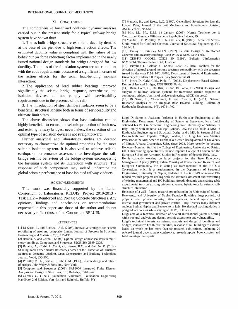
The steel dampers were also implemented in the model. The choice of such dampers was motivated by the outcomes of the application of LRBs, which resulted not viable due to large displacements under traffic railway actions. Steel damper devices comprise of steel fuses, i.e. elements characterized by a shear brittle breaking strength, which transmit to the pier the forces caused by the traffic railway loads, i.e. as fixed supports; nevertheless, they act as isolators during earthquakes because of the breaking of the fuses. The setting of the parameters of the device (ultimate displacement and strength) was computed using the displacement spectrum method [13, 14]; which is an iterative procedure to determine the ultimate displacement from the displacement elastic spectrum, in turn, derived from the acceleration elastic spectrum for the site of the bridge structure. The ultimate strength of the isolator Fu was selected as a function of the yielding bending moment of the pier at the base; the latter was obtained in compliance with the railway code that set the yielding strain of the reinforcement at the 75% of fy,k, i.e. the characterized yielding stress. The result of this procedure led to the following design parameters: ∆y = 15 mm ∆u = 110 mm Fy = 1300 kN Fu = 1650 kN The introduction of these isolators system gave rise to a significant lengthening of the periods of vibration of the bridge structure (T1=1.40 s). However, such periods were lower (about 50% less) than those computed with LRB system. The seismic demand of the system with steel dampers is thus higher than the LRB counterparts (compare the results summarized in Figure 13).
0
500
1000
1500
2000
2500
3000
3500
4000
4500
Multidirectional -N [ kN]- Fixed -H [ kN ]- Fixed -N [ kN ]-
Base fixed bridge structure
LRB
Steel dampers
62%
Fig. 13. Results of support bearings action effects compared with the design values.
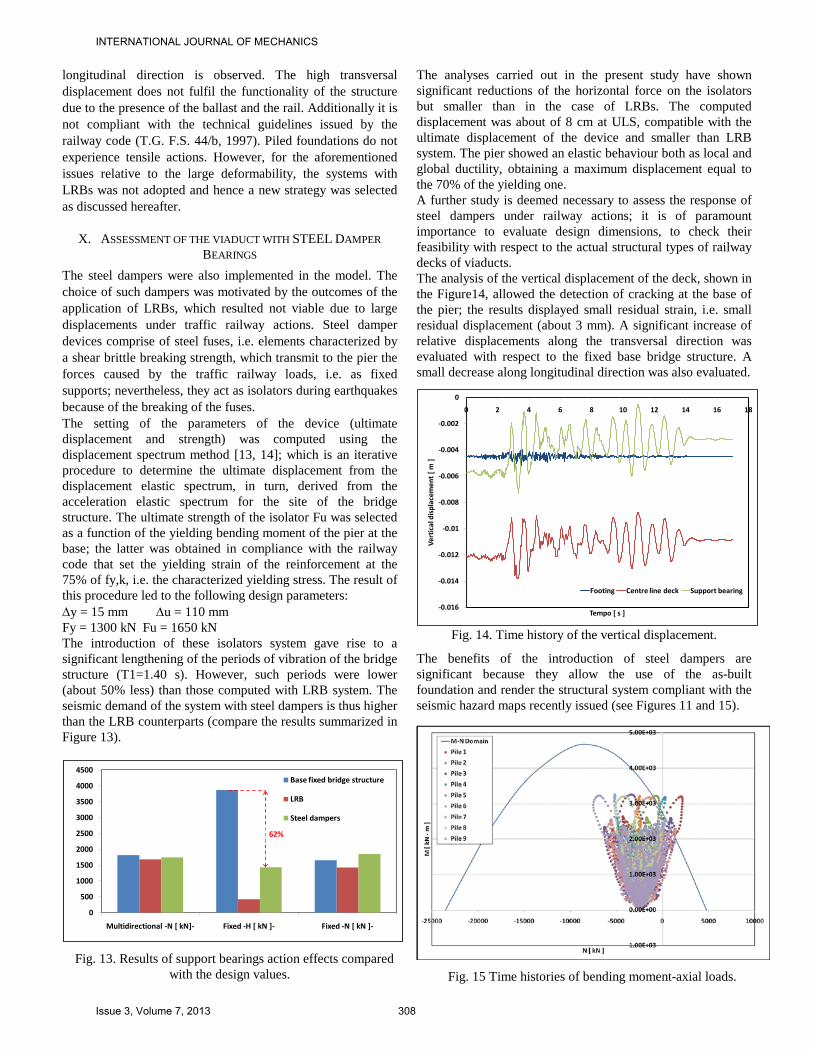
The analyses carried out in the present study have shown significant reductions of the horizontal force on the isolators but smaller than in the case of LRBs. The computed displacement was about of 8 cm at ULS, compatible with the ultimate displacement of the device and smaller than LRB system. The pier showed an elastic behaviour both as local and global ductility, obtaining a maximum displacement equal to the 70% of the yielding one. A further study is deemed necessary to assess the response of steel dampers under railway actions; it is of paramount importance to evaluate design dimensions, to check their feasibility with respect to the actual structural types of railway decks of viaducts. The analysis of the vertical displacement of the deck, shown in the Figure14, allowed the detection of cracking at the base of the pier; the results displayed small residual strain, i.e. small residual displacement (about 3 mm). A significant increase of relative displacements along the transversal direction was evaluated with respect to the fixed base bridge structure. A small decrease along longitudinal direction was also evaluated.
-0.016
-0.014
-0.012
-0.01
-0.008
-0.006
-0.004
-0.002
0
0 2 4 6 8 10 12 14 16 18
Vert
ical
dis
plac
emen
t [ m
]
Tempo [ s ]
Footing Centre line deck Support bearing
Fig. 14. Time history of the vertical displacement.
The benefits of the introduction of steel dampers are significant because they allow the use of the as-built foundation and render the structural system compliant with the seismic hazard maps recently issued (see Figures 11 and 15).
Fig. 15 Time histories of bending moment-axial loads.
INTERNATIONAL JOURNAL OF MECHANICS
Issue 3, Volume 7, 2013 308
XI. CONCLUSIONS The comprehensive linear and nonlinear dynamic analyses
carried out in the present study for a typical railway bridge system have shown that:
1. The as-built bridge structure exhibits a ductility demand at the base of the pier due to high tensile action effects. The estimated ductility value is compliant with the values of the behaviour (or force reduction) factor implemented in the newly issued national design standards for bridges designed for low ductility. The piles of the foundation system are not compliant with the code requirements because of a significant increase of the action effects for the axial load-bending moment interaction;
2. The application of lead rubber bearings improved significantly the seismic bridge response, nevertheless, the isolation devices do not comply with serviceability requirements due to the presence of the rail;
3. The introduction of steel dampers isolators seem to be a beneficial structural scheme both in terms of serviceability and ultimate limit states.
The above discussion shows that base isolation can be highly beneficial to ensure the seismic protection of both new and existing railway bridges; nevertheless, the selection of the optimal type of isolation device is not straightforward.
Further analytical and laboratories studies are deemed necessary to characterize the optimal properties for the most suitable isolation system. It is also vital to achieve reliable earthquake performance assessment to investigate the rail-bridge seismic behaviour of the bridge system encompassing the fastening system and its interaction with structure. The response of such components may indeed undermine the global seismic performance of base isolated railway viaducts.
ACKNOWLEDGMENTS This work was financially supported by the Italian
Consortium of Laboratories RELUIS (Project 2010-2013 - Task 1.1.2 – Reinforced and Precast Concrete Structures). Any opinions, findings and conclusions or recommendations expressed in this paper are those of the author and do not necessarily reflect those of the Consortium RELUIS.
REFERENCES [1] Di Sarno, L. and Elnashai, A.S. (2005). Innovative strategies for seismic retrofitting of steel and composite frames. Journal of Progress in Structural Engineering and Materials, 7(3), 115-135. [2] Baratta, A. and Corbi, I. (2004). Optimal design of base-isolators in multi-storey buildings, Computers and Structures, 82(23-26), 2199-2209. [3] Baratta, A., Corbi, I., Corbi, O., Barros, R.C. and Bairrão, R. (2012). Shaking Table Experimental Researches Aimed at the Protection of Structures Subject to Dynamic Loading, Open Construction and Building Technology Journal, Vol.6, 355-360. [4] Priestley M.J.N., Seible F., Calvi G.M. (1996), Seismic design and retrofit of bridges, John Wiley & Sons Inc., New York. [5] Computer and Structures (2008), SAP2000 integrated Finite Element Analysis and Design of Structures, CSI, Berkeley, California. [6] Gazetas G. (1991), Foundation Vibrations, Foundation Engineering Handbook 2nd Edition, Van Nostrand Reinhold, Buffalo, NY.
[7] Matlock, H., and Reese, L.C. (1960), Generalized Solutions for laterally Loaded Piles, Journal of the Soil Mechanics and Foundations Division, ASCE, Vol.86, No SM5. [8] Min. LL. PP., D.M. 14 January (2008), Norme Tecniche per le Costruzioni, Gazzetta Ufficiale della Repubblica Italiana, 29. [9] Mander, J. B. Priestley, M. J. N. and Park, R. (1988). Theoretical Stress–Strain Model for Confined Concrete, Journal of Structural Engineering, Vol. 114, No 8. [10] Paulay T., Priestley M.J.N. (1992), Seismic Design of Reinforced Concrete and Masonry Buildings, John Wiley & Sons, New York. [11] CEB-FIP MODEL CODE 90 (1993), Bulletin d’information N°213/214, Thomas Telford Ltd., London. [12] Iervolino I., Galasso C. (2008), Rexel 2.2 beta, Toolbox for the selection of natural ground motions spectrum compatibility with the spectrum issued by the code D.M. 14/01/2008, Department of Structural Engineering, University of Federico II, Naples, Italy (www.reluis.it) [13] Pietra D., Calvi G.M., Pinho R. (2008), Displacement-Based Seismic Design of Isolated Bridges, IUSSPRESS, Pavia. [14] Della Corte, G., De Risi, R. and Di Sarno, L. (2013). Design and analysis of bilinear isolation systems for transverse seismic response of continuous bridges. Journal of bridge engineering, ASCE (in press) [15] Di Sarno, L., Chioccarelli, E. and Cosenza, E. (2011). Seismic Response Analysis of An Irregular Base Isolated Building. Bulletin of Earthquake Engineering, 9(5), 1673-1702 Luigi Di Sarno is Assistant Professor in Earthquake Engineering at the Engineering Department, University of Sannio at Benevento, Italy. Luigi obtained his PhD in Structural Engineering from University of Salerno, in Italy, jointly with Imperial College, London, UK. He also holds a MSc in Earthquake Engineering and Structural Design and a MSc in Structural Steel Design both from Imperial College, London, UK. Luigi has been Visiting Professor at the Mid-America Earthquake Center, headquartered at University of Illinois, Urbana-Champaign, USA, since 2003. More recently, he became Honorary Member Staff at the College of Engineering, University of Bristol, UK. Other visiting appointments include Imperial College of London and the European School for Advanced Studies in Reduction of Seismic Risk, Italy. He is currently working on large projects for the State Emergency Management Agency (DPC), Italian Ministry of Education and Research and European Community. He is acting as team-member of the RELUIS Consortium, which is a headquartered in the Department of Structural Engineering, University of Naples, Federico II. He is Co-PI of several EU-funded research projects dealing with the seismic assessment and retrofitting of existing monumental and RC buildings, pseudo-dynamic and shaking table experimental tests on existing bridges, advanced hybrid tests for seismic soil-structure interaction. He is part of a well - funded research group based in the University of Sannio, Benevento, and University of Naples Federico II, with a large portfolio of projects from private industry, state agencies, federal agencies, and international government and private entities. Luigi teaches many different subjects both at Naples and Benevento in Italy. He also had teaching duties in postgraduate courses while staying at UIUC, in Illinois. Luigi acts as a technical reviewer of several international journals dealing with structural analysis and design, seismic assessment and vulnerability. Luigi’s technical interests are seismic analysis and design of buildings and bridges, innovative health care facilities, response of tall buildings to extreme loads, on which he has more than 90 research publications, including 20 refereed journal papers, many conference, research reports, book chapters and field investigation reports.
INTERNATIONAL JOURNAL OF MECHANICS
Issue 3, Volume 7, 2013 309