Embed Size (px)
Citation preview
RESEARCH REPORT VTT-R-01364-14
Barriers and opportunitiesof structural elements re-useAuthors: Petr Hradil
Confidentiality: Public

RESEARCH REPORT VTT-R-01363-142 (44)
Preface
This report was created within the Ministry of the Environment research project ReUSERakennuselementtien uudelleenkäyttö. The project aims at C&D waste reduction,preservation of natural resources and overall decrease of environmental impacts of buildingsby encouraging the re- use of the building components. It is closely related to the nationalprogramme promoting resource and material efficiency Kestävää kasvuamateriaalitehokkuudella. The project is jointly funded by the Ministry of the Environment, VTTTechnical Research Centre of Finland, Tampere University of Technology, Ekokem andFinnish Wood Research. The following members of the project Steering Group wereappointed to supervise the implementation of the project goals:
Else Peuranen, Ministry of the EnvironmentJaakko Lehto, Finnish Wood Research OyToni Andersson, Ekokem Oy AbAri Hynynen, Tampere University of TechnologyHenna Luukkonen, Association of Finnish Local and Regional AuthoritiesLaura Majoinen, NCC Rakennus OyEila Lehmus, VTT
In addition, five seminars are organized within the project for the broader audience includingthe External Advisory Group which consist of the representatives of the Finnish ConcreteIndustry Association, Finnish Forest Industries, Rautaruukki, Kuusakoski Recycling,Metsänkylän Navetta, Forssa Region Development Centre, City of Kotka, City of Lahti,Kouvola Innovation, Umacon, Finnish Environment Institute and Finnish Funding Agency forTechnology and Innovation.
I wish to express my gratitude to the project sponsors and the members of the Steering andExternal Advisory Groups and other participant of the project seminars.
Espoo 17.3.2014
Petr Hradil

RESEARCH REPORT VTT-R-01363-143 (44)
Contents
Preface ................................................................................................................................... 2
1. Introduction ....................................................................................................................... 41.1 Scope of the report ................................................................................................... 41.2 Building materials efficiency in EU ............................................................................ 51.3 Building materials efficiency in Finland ..................................................................... 6
2. Structural elements ........................................................................................................... 8
3. Environmental certification systems for sustainable buildings ......................................... 113.1 BREEAM ................................................................................................................ 133.2 LEED ...................................................................................................................... 143.3 GreenStar ............................................................................................................... 143.4 DGNB ..................................................................................................................... 15
4. Business concepts .......................................................................................................... 16
5. Re-using opportunities .................................................................................................... 185.1 Economic opportunities ........................................................................................... 185.2 Social opportunities ................................................................................................ 195.3 Environmental opportunities.................................................................................... 195.4 Technological opportunities .................................................................................... 19
6. Re-using barriers ............................................................................................................ 206.1 Economic barriers ................................................................................................... 206.2 Social barriers ......................................................................................................... 206.3 Environmental barriers ............................................................................................ 216.4 Technological barriers............................................................................................. 216.5 Evaluation of re-using barriers ................................................................................ 21
7. Steel and timber building frames ..................................................................................... 237.1 Steel re-using ......................................................................................................... 247.2 Timber re-using....................................................................................................... 247.3 Case study: LCA of steel element ........................................................................... 26
7.3.1 Goal and scope ........................................................................................... 267.3.2 Functional unit ............................................................................................ 267.3.3 System description ...................................................................................... 277.3.4 Results ........................................................................................................ 32
7.4 Case study: Dynamic simulation of wood-housing .................................................. 337.4.1 Goal and scope ........................................................................................... 347.4.2 Functional unit ............................................................................................ 347.4.3 System description and boundaries ............................................................ 347.4.4 Results ........................................................................................................ 39
8. Conclusions .................................................................................................................... 42
References ........................................................................................................................... 43
RESEARCH REPORT VTT-R-01363-144 (44)
1. Introduction
A large quantity of waste is generated during the production of building components and afterthe building demolition. Construction and demolition activities in Europe are responsible for40 - 50% of solid waste production which was estimated over 460 million tonnes per year inEU-27 (about 1.1 tonnes per person per year) excluding excavations [1]. It contains mostlyminerals from the structures.
The construction sector also consumes about half of all natural resources extracted inEurope yearly, that have very high energy demands on their transformation into buildingproducts. It has been estimated that 40 - 50% of all extracted raw materials are transformedinto building products. The construction sector uses vast amounts of energy in the first threestages of the production process: resource generation, resource extraction and intermediateproduct manufacture.
Therefore the focus of today’s environmental policy is on the building end-of-life scenariosand material efficiency. Recycling and material re-use becomes the common practice, but itis not always environmentally efficient, and material separation of composite structures isvery challenging.
Building elements have often longer service life than the building itself and are, therefore,suitable for recovery and re-use after deconstruction. However, component re-use is still notwidespread practice because of technological and institutional barriers. Structuralcomponents are not usually designed to be re-used, even though they are designed fordeconstruction in some cases.
1.1 Scope of the report
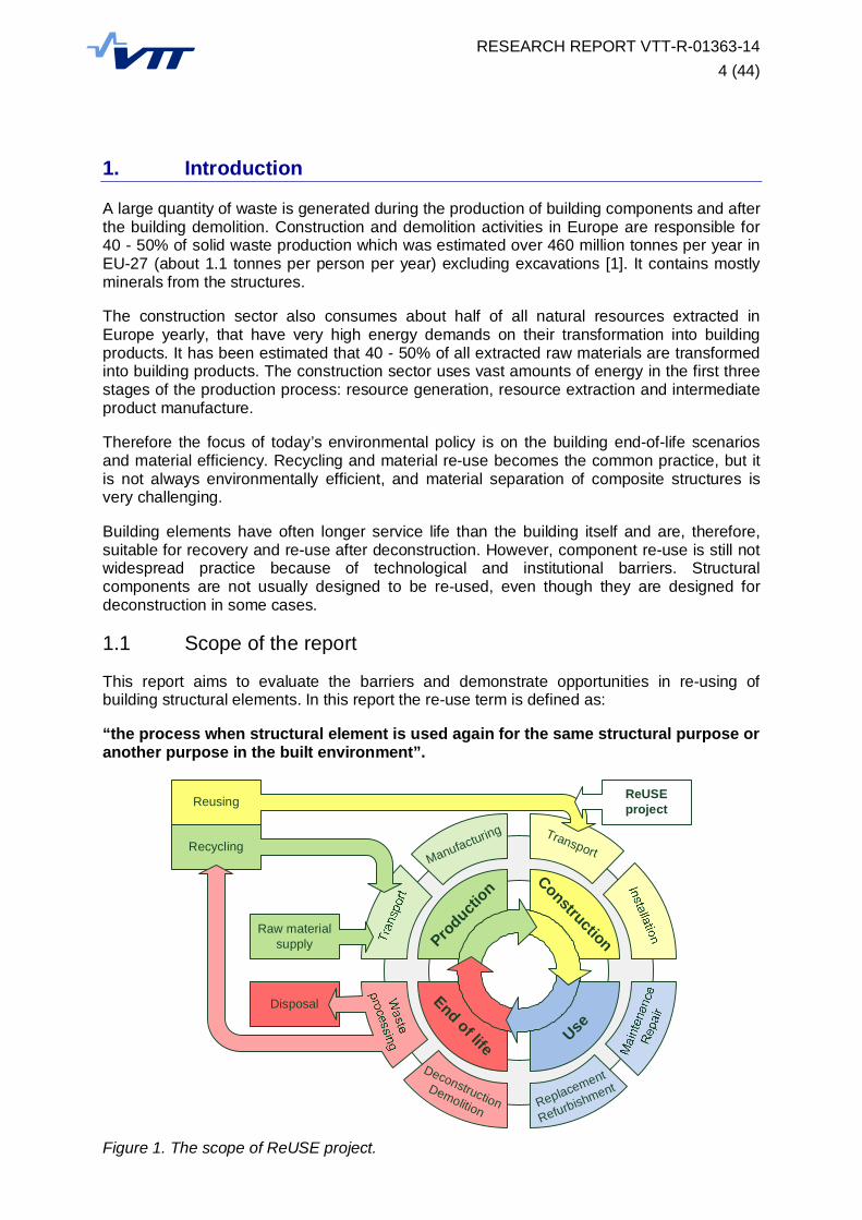
This report aims to evaluate the barriers and demonstrate opportunities in re-using ofbuilding structural elements. In this report the re-use term is defined as:
“the process when structural element is used again for the same structural purpose oranother purpose in the built environment”.
Figure 1. The scope of ReUSE project.
UseEnd of life
Producti
onConstruction
Manufacturing Transport
Replacement
RefurbishmentDeconstructionDemolition
Disposal
Raw materialsupply
Recycling
Reusing ReUSEproject
RESEARCH REPORT VTT-R-01363-145 (44)
The structural elements are parts of the load-carrying structure of the building or thesecondary elements such as cladding and roofing panels. As a special case the wholestructure can be considered as a single re-usable object if it is removed to a different locationin exactly the same configuration as it was originally designed.
The basic materials covered in the presented studies are divided into three groups:(1) Timber - structural timber, engineered wood products (such as glulam, LVL) and wood
based panels(2) Steel - structural carbon and stainless steels, other alloys used in load-carrying
structures may be also included(3) Concrete - plain, reinforced or pre-stressed concrete elements or similar masonry
products.
This report focuses mostly on steel and timber elements while the concrete buildings arediscussed in more detail in the report provided by TTY.
1.2 Building materials efficiency in EU
The European Parliament and Council published the revised directive on waste in 2008 [2]laying down the measures to prevent the negative effects of waste generation and to set upthe overall rules for waste management.
Waste is defined in this directive as “any substance or object which the holder discards orintends or is required to discard”. Re-use means according to the directive “any operation bywhich products or components that are not waste are used again for the same purpose forwhich they were conceived”. Preparing for re-use means “checking, cleaning or repairingrecovery operations, by which products or components of products that have become wasteare prepared so that they can be re-used without any other pre-processing”.
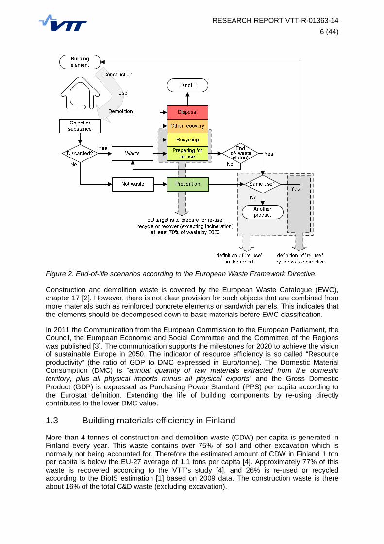
In that sense, the scope of the project can be divided into two cases: (a) objects that arediscarded, recovered and prepared for re-use, and (b) objects that are not discarded andtheir holder is arranging the re-use instead. It should be noted that the definition of “re-use” inthe directive is rather narrow (see Figure 2) and components that are not becoming waste,but are used for the different purpose are not covered by the definition. In the first case(object becoming waste), the end-of-waste criteria have to be fulfilled for successful re-using, especially that “(a) the substance or object is commonly used for specific purposes,(b) a market or demand exists for such a substance or object, (c) the substance or objectfulfils the technical requirements for the specific purposes and meets the existing legislationand standards applicable to products; and (d) the use of the substance or object will not leadto overall adverse environmental or human health impacts.” The conditions (a) and (b) arecommon prerequisites for both re-using paths, but the conditions (c) and (d) do not have tobe necessarily fulfilled if the object is not discarded and therefore not becoming waste.
The waste management policies should follow the hierarchy defined in the directive: (a)prevention, (b) preparing for re-use, (c) recycling, (d) other recovery and (e) disposal.However, when the overall impacts are justified by the life-cycle calculations, differenthierarchy may be applied. The directive sets a goal of minimum 70% of construction anddemolition waste (by weight) shall be prepared for re-use, recycled or recovered by 2020.Unfortunately, this goal does not take into account waste prevention, and therefore all thebuilding elements re-used without becoming a waste decrease the percentage of recoveredwaste by decreasing the overall amount of waste. We recommend the directive to beamended to correct this drawback.
RESEARCH REPORT VTT-R-01363-146 (44)
Figure 2. End-of-life scenarios according to the European Waste Framework Directive.
Construction and demolition waste is covered by the European Waste Catalogue (EWC),chapter 17 [2]. However, there is not clear provision for such objects that are combined frommore materials such as reinforced concrete elements or sandwich panels. This indicates thatthe elements should be decomposed down to basic materials before EWC classification.
In 2011 the Communication from the European Commission to the European Parliament, theCouncil, the European Economic and Social Committee and the Committee of the Regionswas published [3]. The communication supports the milestones for 2020 to achieve the visionof sustainable Europe in 2050. The indicator of resource efficiency is so called “Resourceproductivity” (the ratio of GDP to DMC expressed in Euro/tonne). The Domestic MaterialConsumption (DMC) is “annual quantity of raw materials extracted from the domesticterritory, plus all physical imports minus all physical exports” and the Gross DomesticProduct (GDP) is expressed as Purchasing Power Standard (PPS) per capita according tothe Eurostat definition. Extending the life of building components by re-using directlycontributes to the lower DMC value.
1.3 Building materials efficiency in Finland
More than 4 tonnes of construction and demolition waste (CDW) per capita is generated inFinland every year. This waste contains over 75% of soil and other excavation which isnormally not being accounted for. Therefore the estimated amount of CDW in Finland 1 tonper capita is below the EU-27 average of 1.1 tons per capita [4]. Approximately 77% of thiswaste is recovered according to the VTT’s study [4], and 26% is re-used or recycledaccording to the BioIS estimation [1] based on 2009 data. The construction waste is thereabout 16% of the total C&D waste (excluding excavation).
RESEARCH REPORT VTT-R-01363-147 (44)
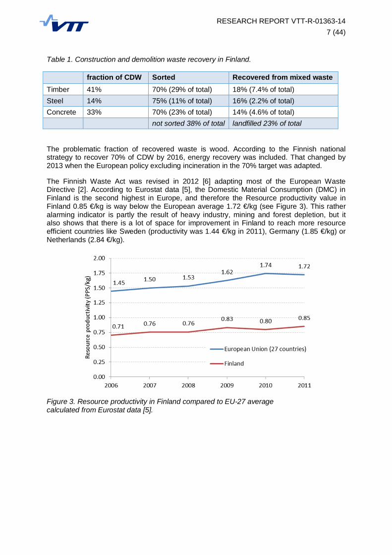
Table 1. Construction and demolition waste recovery in Finland.
fraction of CDW Sorted Recovered from mixed wasteTimber 41% 70% (29% of total) 18% (7.4% of total)Steel 14% 75% (11% of total) 16% (2.2% of total)Concrete 33% 70% (23% of total) 14% (4.6% of total)
not sorted 38% of total landfilled 23% of total
The problematic fraction of recovered waste is wood. According to the Finnish nationalstrategy to recover 70% of CDW by 2016, energy recovery was included. That changed by2013 when the European policy excluding incineration in the 70% target was adapted.
The Finnish Waste Act was revised in 2012 [6] adapting most of the European WasteDirective [2]. According to Eurostat data [5], the Domestic Material Consumption (DMC) inFinland is the second highest in Europe, and therefore the Resource productivity value inFinland 0.85 €/kg is way below the European average 1.72 €/kg (see Figure 3). This ratheralarming indicator is partly the result of heavy industry, mining and forest depletion, but italso shows that there is a lot of space for improvement in Finland to reach more resourceefficient countries like Sweden (productivity was 1.44 €/kg in 2011), Germany (1.85 €/kg) orNetherlands (2.84 €/kg).
Figure 3. Resource productivity in Finland compared to EU-27 averagecalculated from Eurostat data [5].

RESEARCH REPORT VTT-R-01363-148 (44)
2. Structural elements
There is a large variety of building elements that are part of load-carrying structure and canbe re-used. Some of them are successfully salvaged from the construction and demolitionwaste, some are even re-used without becoming a waste. They can be divided according totheir size and complexity into the following five categories (see Figure 4).
Figure 4. Re-usable structural element categories.
(a) Category A: Buildings
The whole buildings or standalone building modules can be technologically very easyto disassembly and re-use. However, the flexibility of new design is very limited.Typical representatives are:
Timber: modular houses, sports halls, bridges, towersSteel: industrial halls, container buildings, bridges, towersConcrete: industrial halls, shopping centres, bridges
(b) Category B: Structures
Structures are typically composed of more structural members and need to bedisassembled before re-using. They can be re-used in a different building design, buttheir spans and connection points should be carefully taken into account. Typicalrepresentatives are:
Timber: glulam frames, roof trussesSteel: portal frames, truss girdersConcrete: prefabricated systems for commercial, industrial or office buildings
(c) Category C: Structural members
Such elements are designed with well-defined shape and fitted connections. Theycan be composed from more materials or smaller elements. The members can berepaired if they are damaged during the disassembly, but their modification needs tobe carried out in the workshop. Typical representatives are:
Timber: sandwich panels, curved glulam beams, ceiling joistsSteel: sandwich panels, hollow beams, beams with corrugated websConcrete: pre-stressed beams and panels, ceiling joists, sandwich panels
A: Buildings
B: Structures
C: Structural members
D: Basic structural elements
E: Building blocks
RESEARCH REPORT VTT-R-01363-149 (44)
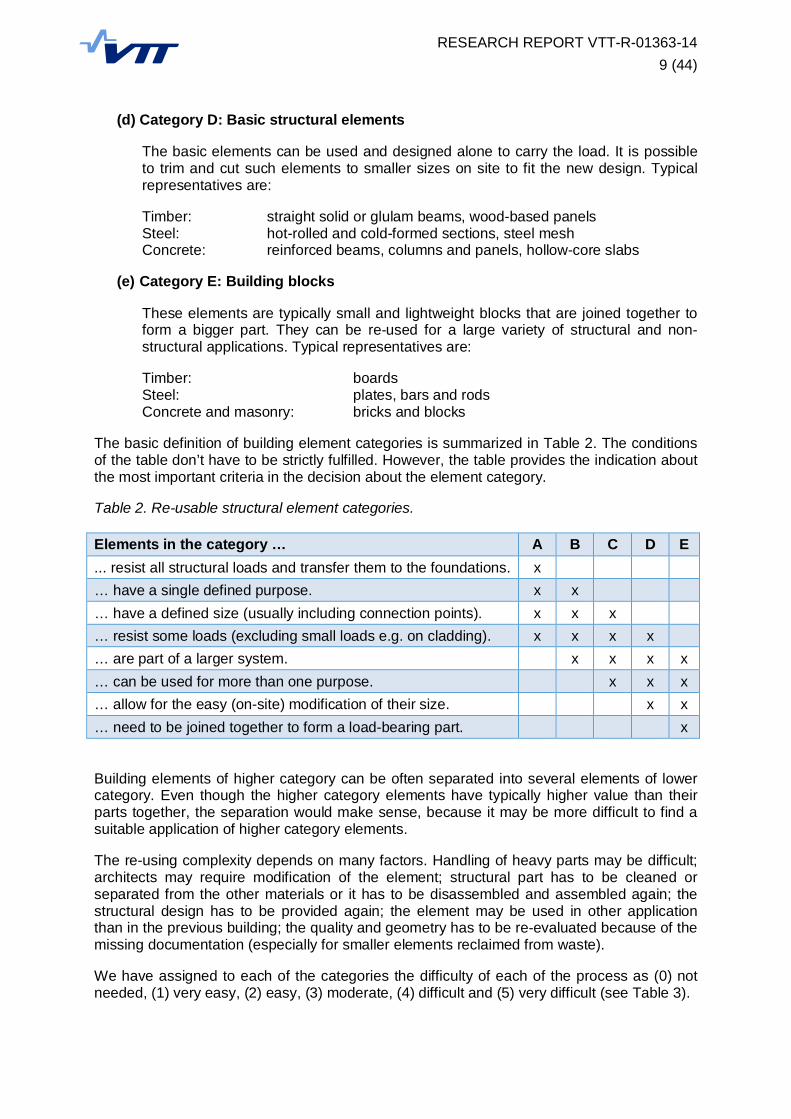
(d) Category D: Basic structural elements
The basic elements can be used and designed alone to carry the load. It is possibleto trim and cut such elements to smaller sizes on site to fit the new design. Typicalrepresentatives are:
Timber: straight solid or glulam beams, wood-based panelsSteel: hot-rolled and cold-formed sections, steel meshConcrete: reinforced beams, columns and panels, hollow-core slabs
(e) Category E: Building blocks
These elements are typically small and lightweight blocks that are joined together toform a bigger part. They can be re-used for a large variety of structural and non-structural applications. Typical representatives are:
Timber: boardsSteel: plates, bars and rodsConcrete and masonry: bricks and blocks
The basic definition of building element categories is summarized in Table 2. The conditionsof the table don’t have to be strictly fulfilled. However, the table provides the indication aboutthe most important criteria in the decision about the element category.
Table 2. Re-usable structural element categories.
Elements in the category … A B C D E... resist all structural loads and transfer them to the foundations. x… have a single defined purpose. x x… have a defined size (usually including connection points). x x x… resist some loads (excluding small loads e.g. on cladding). x x x x… are part of a larger system. x x x x… can be used for more than one purpose. x x x… allow for the easy (on-site) modification of their size. x x… need to be joined together to form a load-bearing part. x
Building elements of higher category can be often separated into several elements of lowercategory. Even though the higher category elements have typically higher value than theirparts together, the separation would make sense, because it may be more difficult to find asuitable application of higher category elements.
The re-using complexity depends on many factors. Handling of heavy parts may be difficult;architects may require modification of the element; structural part has to be cleaned orseparated from the other materials or it has to be disassembled and assembled again; thestructural design has to be provided again; the element may be used in other applicationthan in the previous building; the quality and geometry has to be re-evaluated because of themissing documentation (especially for smaller elements reclaimed from waste).
We have assigned to each of the categories the difficulty of each of the process as (0) notneeded, (1) very easy, (2) easy, (3) moderate, (4) difficult and (5) very difficult (see Table 3).
RESEARCH REPORT VTT-R-01363-1410 (44)
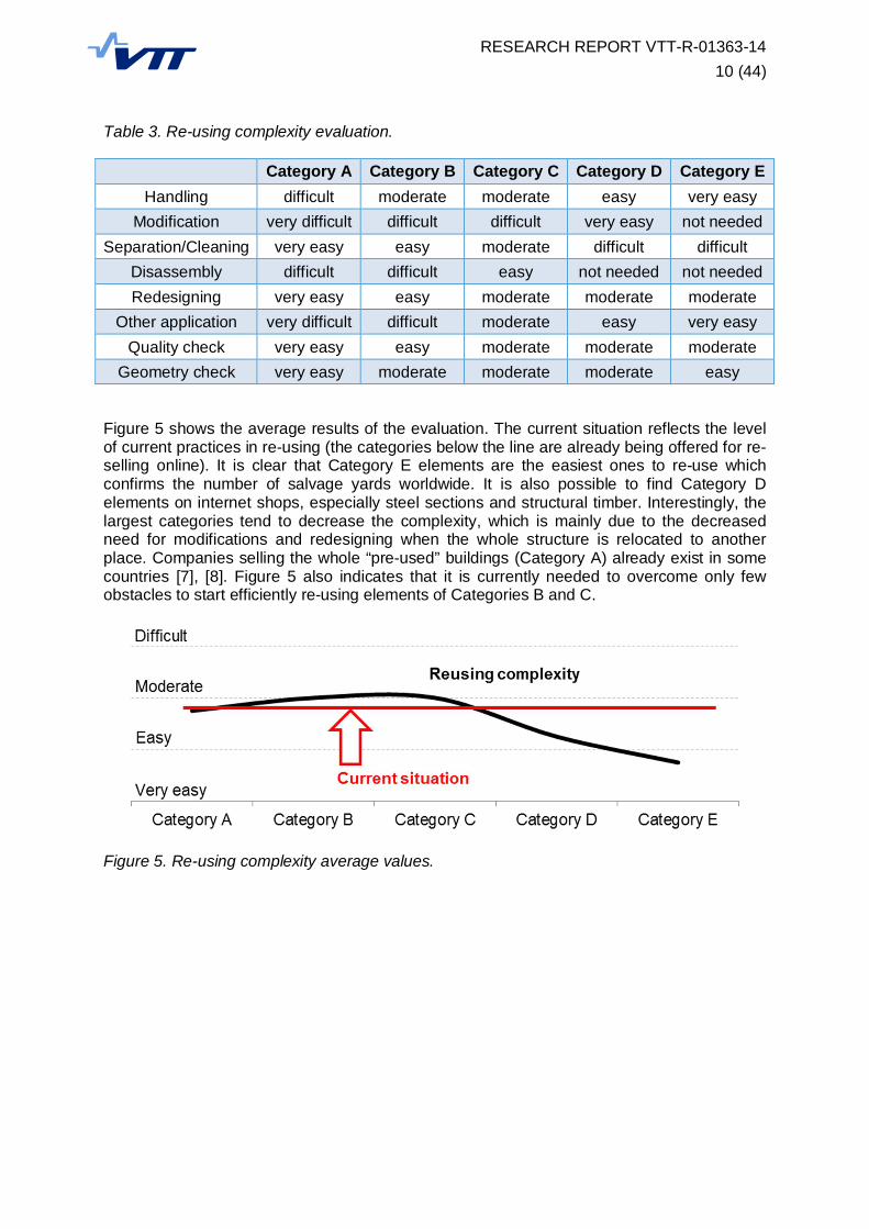
Table 3. Re-using complexity evaluation.
Category A Category B Category C Category D Category EHandling difficult moderate moderate easy very easy
Modification very difficult difficult difficult very easy not neededSeparation/Cleaning very easy easy moderate difficult difficult
Disassembly difficult difficult easy not needed not neededRedesigning very easy easy moderate moderate moderate
Other application very difficult difficult moderate easy very easyQuality check very easy easy moderate moderate moderate
Geometry check very easy moderate moderate moderate easy
Figure 5 shows the average results of the evaluation. The current situation reflects the levelof current practices in re-using (the categories below the line are already being offered for re-selling online). It is clear that Category E elements are the easiest ones to re-use whichconfirms the number of salvage yards worldwide. It is also possible to find Category Delements on internet shops, especially steel sections and structural timber. Interestingly, thelargest categories tend to decrease the complexity, which is mainly due to the decreasedneed for modifications and redesigning when the whole structure is relocated to anotherplace. Companies selling the whole “pre-used” buildings (Category A) already exist in somecountries [7], [8]. Figure 5 also indicates that it is currently needed to overcome only fewobstacles to start efficiently re-using elements of Categories B and C.
Figure 5. Re-using complexity average values.

RESEARCH REPORT VTT-R-01363-1411 (44)
3. Environmental certification systems for sustainablebuildings
A great number of certification systems to assess the environmental quality of buildings wasintroduced during the last decades. They have a significant impact on many project decisionsworldwide. The following chapter is based on the Simply Green publication [10], FORCEreport [11] and the data provided by certification authorities on their internet portals. Itsummarizes the most important certification systems with the focus on building resourceefficiency, materials and waste management.
The certification systems are being developed and promoted mostly by the national branchesof the Green Building Council (GBC) or by the similar organizations. Finland’s owncertification system PromisE is outdated and not used anymore. Even though there is notany localization of the most common foreign certificates in Finland, it is still possible toassess the building by the international versions of several systems such as BREEAM,LEED, DGNB and HQE (see Table 4).
Table 4. The selected environmental certification systems.
Certificationsystem
CountryLaunched
Localized versionsin other countries Applicable in Finland
BREEAMUK1990
Sweden, Norway, Germany,Netherlands, Spain, Austria
BREEAM International BespokeBREEAM Europe Commercial
LEED USA2000
Canada, India, Cuba, Italy via USGBC (US standards)
DGNBGermany2009
Denmark, Switzerland,Austria, Bulgaria, Thailand
DGNB International (EN/ISOstandards)
GreenStar Australia2002
New Zealand, South Africa -
MiljöbyggnadSweden2009 - -
HQEFrance2004
Brazil, Lebanon HQE International (EN/ISOstandards)
CASBEEJapan2002 - -
IGBCIndia2007
Nepal, Bangladesh -
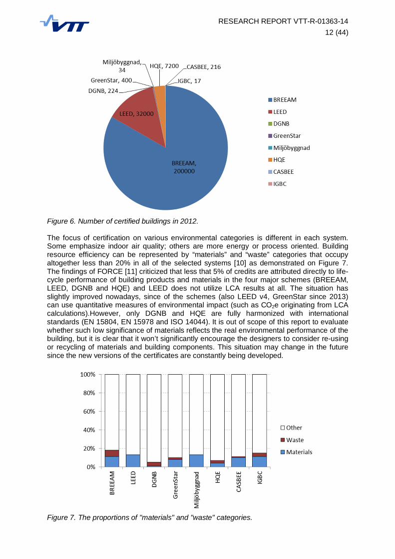
It is very likely that the common European certification system will be developed in the nearfuture because of the strong need to measure the progress towards the strategies forsustainable Europe [3]. It may be based on the existing schemes that are already applied tothousands of buildings (see Figure 6) and are following the European and internationalstandards (see Table 4). However, it would be very difficult to harmonize certificationprocedures in Europe because the current methods are strongly depending on the localbuilding practices and the climate.
RESEARCH REPORT VTT-R-01363-1412 (44)
Figure 6. Number of certified buildings in 2012.
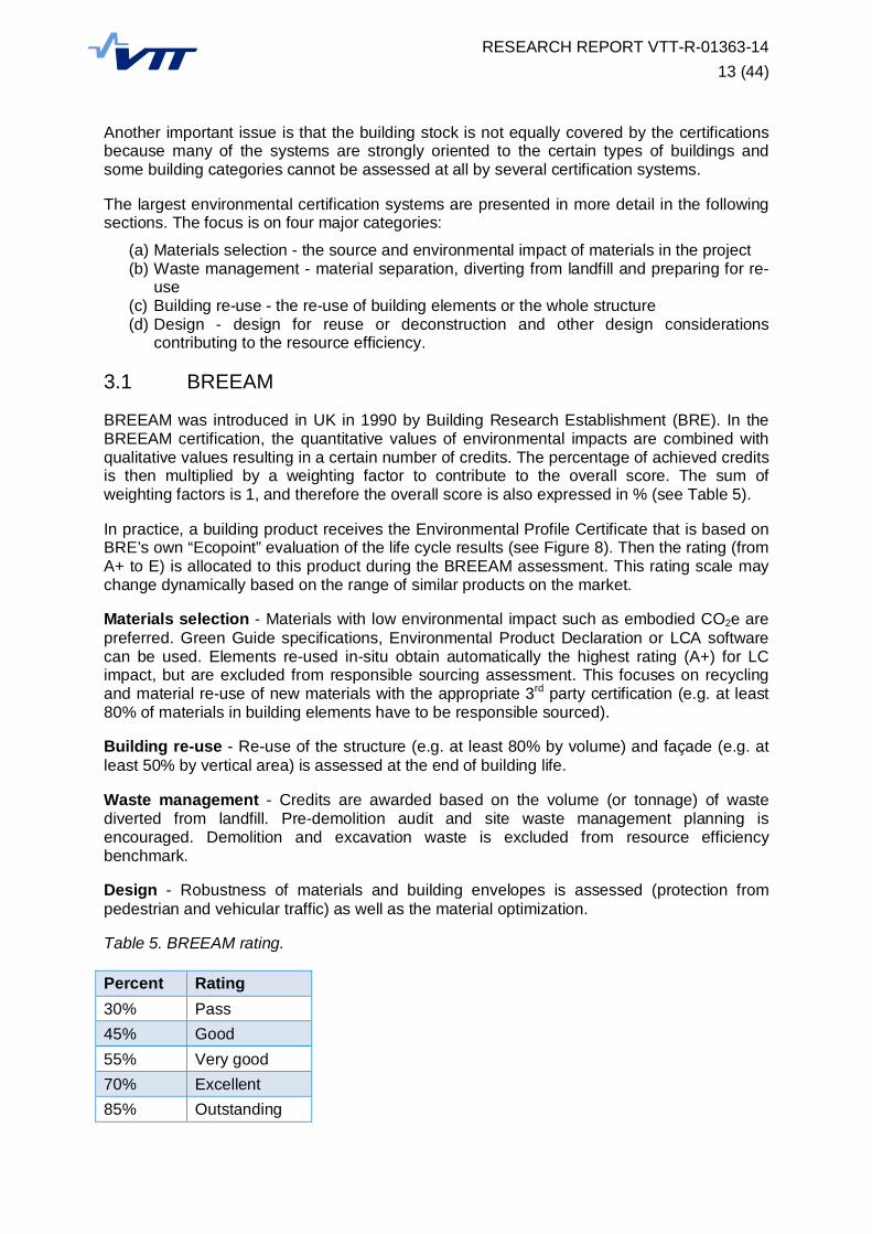
The focus of certification on various environmental categories is different in each system.Some emphasize indoor air quality; others are more energy or process oriented. Buildingresource efficiency can be represented by “materials” and “waste” categories that occupyaltogether less than 20% in all of the selected systems [10] as demonstrated on Figure 7.The findings of FORCE [11] criticized that less that 5% of credits are attributed directly to life-cycle performance of building products and materials in the four major schemes (BREEAM,LEED, DGNB and HQE) and LEED does not utilize LCA results at all. The situation hasslightly improved nowadays, since of the schemes (also LEED v4, GreenStar since 2013)can use quantitative measures of environmental impact (such as CO2e originating from LCAcalculations).However, only DGNB and HQE are fully harmonized with internationalstandards (EN 15804, EN 15978 and ISO 14044). It is out of scope of this report to evaluatewhether such low significance of materials reflects the real environmental performance of thebuilding, but it is clear that it won’t significantly encourage the designers to consider re-usingor recycling of materials and building components. This situation may change in the futuresince the new versions of the certificates are constantly being developed.
Figure 7. The proportions of "materials" and "waste" categories.
RESEARCH REPORT VTT-R-01363-1413 (44)
Another important issue is that the building stock is not equally covered by the certificationsbecause many of the systems are strongly oriented to the certain types of buildings andsome building categories cannot be assessed at all by several certification systems.
The largest environmental certification systems are presented in more detail in the followingsections. The focus is on four major categories:
(a) Materials selection - the source and environmental impact of materials in the project(b) Waste management - material separation, diverting from landfill and preparing for re-
use(c) Building re-use - the re-use of building elements or the whole structure(d) Design - design for reuse or deconstruction and other design considerations
contributing to the resource efficiency.
3.1 BREEAM
BREEAM was introduced in UK in 1990 by Building Research Establishment (BRE). In theBREEAM certification, the quantitative values of environmental impacts are combined withqualitative values resulting in a certain number of credits. The percentage of achieved creditsis then multiplied by a weighting factor to contribute to the overall score. The sum ofweighting factors is 1, and therefore the overall score is also expressed in % (see Table 5).
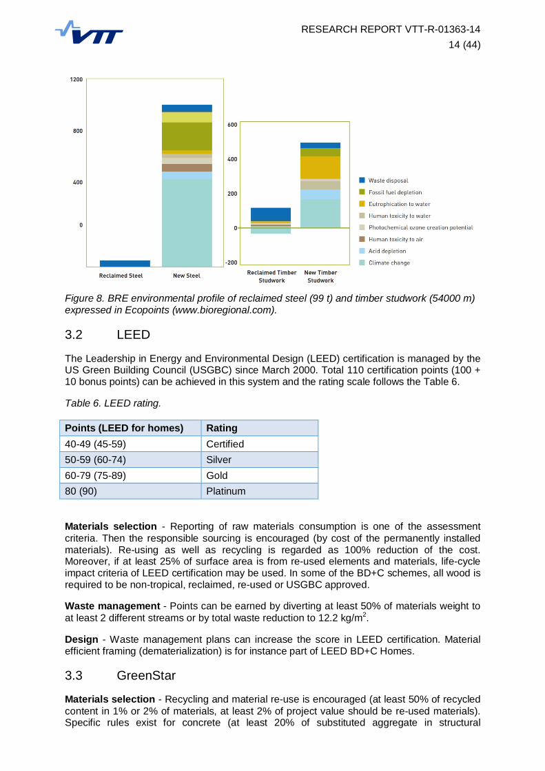
In practice, a building product receives the Environmental Profile Certificate that is based onBRE’s own “Ecopoint” evaluation of the life cycle results (see Figure 8). Then the rating (fromA+ to E) is allocated to this product during the BREEAM assessment. This rating scale maychange dynamically based on the range of similar products on the market.
Materials selection - Materials with low environmental impact such as embodied CO2e arepreferred. Green Guide specifications, Environmental Product Declaration or LCA softwarecan be used. Elements re-used in-situ obtain automatically the highest rating (A+) for LCimpact, but are excluded from responsible sourcing assessment. This focuses on recyclingand material re-use of new materials with the appropriate 3rd party certification (e.g. at least80% of materials in building elements have to be responsible sourced).
Building re-use - Re-use of the structure (e.g. at least 80% by volume) and façade (e.g. atleast 50% by vertical area) is assessed at the end of building life.
Waste management - Credits are awarded based on the volume (or tonnage) of wastediverted from landfill. Pre-demolition audit and site waste management planning isencouraged. Demolition and excavation waste is excluded from resource efficiencybenchmark.
Design - Robustness of materials and building envelopes is assessed (protection frompedestrian and vehicular traffic) as well as the material optimization.
Table 5. BREEAM rating.
Percent Rating30% Pass45% Good55% Very good70% Excellent85% Outstanding
RESEARCH REPORT VTT-R-01363-1414 (44)
Figure 8. BRE environmental profile of reclaimed steel (99 t) and timber studwork (54000 m)expressed in Ecopoints (www.bioregional.com).
3.2 LEED
The Leadership in Energy and Environmental Design (LEED) certification is managed by theUS Green Building Council (USGBC) since March 2000. Total 110 certification points (100 +10 bonus points) can be achieved in this system and the rating scale follows the Table 6.
Table 6. LEED rating.
Points (LEED for homes) Rating40-49 (45-59) Certified50-59 (60-74) Silver60-79 (75-89) Gold80 (90) Platinum
Materials selection - Reporting of raw materials consumption is one of the assessmentcriteria. Then the responsible sourcing is encouraged (by cost of the permanently installedmaterials). Re-using as well as recycling is regarded as 100% reduction of the cost.Moreover, if at least 25% of surface area is from re-used elements and materials, life-cycleimpact criteria of LEED certification may be used. In some of the BD+C schemes, all wood isrequired to be non-tropical, reclaimed, re-used or USGBC approved.
Waste management - Points can be earned by diverting at least 50% of materials weight toat least 2 different streams or by total waste reduction to 12.2 kg/m2.
Design - Waste management plans can increase the score in LEED certification. Materialefficient framing (dematerialization) is for instance part of LEED BD+C Homes.
3.3 GreenStar
Materials selection - Recycling and material re-use is encouraged (at least 50% of recycledcontent in 1% or 2% of materials, at least 2% of project value should be re-used materials).Specific rules exist for concrete (at least 20% of substituted aggregate in structural

RESEARCH REPORT VTT-R-01363-1415 (44)
elements), steel (at least 50% re-used or recycled) and timber (at least 95% re-used,recycled or FSC certified).
Building re-use - Re-use of the structure (by volume) and façade (by vertical area) isassessed at the end of building life. This idea is similar to BREEAM assessment.
Design - Points are awarded for design for disassembly (at least 50% of the area or 95% ofthe façade has to be designed for disassembly) and high material utilization (significantreduction of building materials when the function and integrity is maintained).
Table 7. GreenStar rating.
Points Rating10-19 p
20-29 p
30-44 p
45-59 p Best practice
60-74 p Australian Excellence
75+ p World Leadership
3.4 DGNB
The German Sustainable Building Certificate DGNB was established by German SustainableBuilding Council in 2009 and it is considered as the second generation certification system.Even though only small number of buildings has been certified since its introduction, it iscompatible with the new European legislation, and therefore it can be easily adopted for usein EU member countries.
Table 8. DGNB rating.
Percent Rating50% Bronze65% Silver80% Gold
The assessment criteria are based on the ecological, economical, socio-cultural, technicaland process quality. The quantitative life-cycle results are based on the German Ökobau.datdatabase or DNGB’s own database called ESUCO that has the ambition to serve as theEuropean reference database. Those results are multiplied by EGNB’s own weighting factorsto contribute to the overall score for the ecological quality assessment.
The quantitative impacts of material production and disposal are usually less that 25% oftotal impact. They contribute to 7 out of 11 categories in environmental quality assessment ofDGNB which occupies 22.5% of the total rating. Therefore the changes of environmentalimpact due to material sourcing and waste treatment of a building component have almost nocontribution (less than 0.1%) to the overall results of DGNB certification [11].

RESEARCH REPORT VTT-R-01363-1416 (44)
4. Business concepts
The following scenarios demonstrate the basic concepts of transferring the ownership andresponsibility of re-used elements in relation to their physical flow from producer tocontractor, owner, contractor and eventually the new owner.
(a) Re-using via salvage yards - The most common way of re-using especially smallerelements is by selling them after sorting and cleaning to the salvage yard where theyare stored and offered for another use (Figure 9). The role of salvage yard can be alsotaken by the recycling companies. This approach is suitable for basic elements suchas wood framing, steel sections, boards and some common types of structural panels.
Figure 9. Re-using via salvage yards.
(b) Direct re-selling - When handling more complex or unique building elements, or thewhole structural systems, the building owner may decide to find the suitableapplication directly. In that situation the storing and transport costs are usually lower;however, such cases are very rare due to many limitations (Figure 10). This approachis suitable for the structural systems such as industrial hall frames or roof trusses.
Figure 10. Direct re-selling.
(c) Producer takes the responsibility - The manufacturers are usually best equipped todisassemble the product and the European legislation is moving in the direction ofshifting the end-of-life responsibility to them [2]. The limitation is obviously theextremely long service life of the building, and therefore some alternative ways shouldexist in the case of non-existing producer at the time of deconstruction (Figure 11).This approach is suitable for the commonly used building elements that are, however,unique for each producer such as cladding panels. Shorter service life of the buildingis an advantage.
RESEARCH REPORT VTT-R-01363-1417 (44)
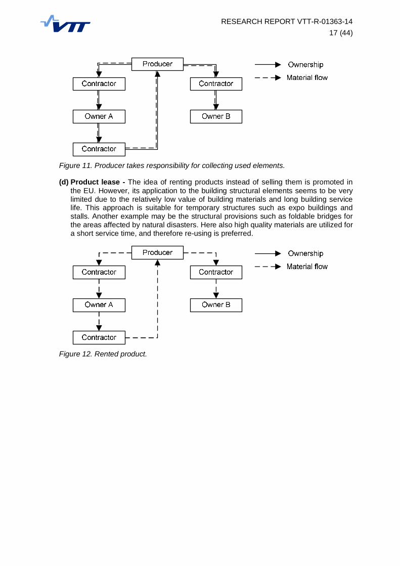
Figure 11. Producer takes responsibility for collecting used elements.
(d) Product lease - The idea of renting products instead of selling them is promoted inthe EU. However, its application to the building structural elements seems to be verylimited due to the relatively low value of building materials and long building servicelife. This approach is suitable for temporary structures such as expo buildings andstalls. Another example may be the structural provisions such as foldable bridges forthe areas affected by natural disasters. Here also high quality materials are utilized fora short service time, and therefore re-using is preferred.
Figure 12. Rented product.
RESEARCH REPORT VTT-R-01363-1418 (44)
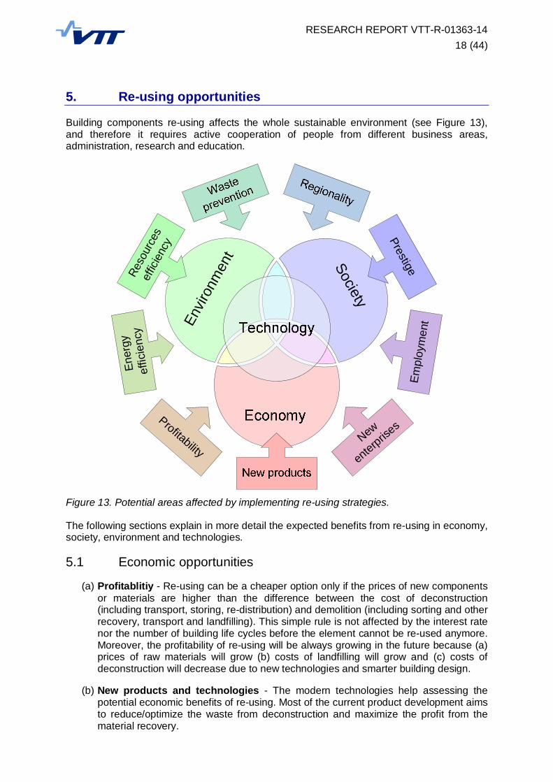
5. Re-using opportunities
Building components re-using affects the whole sustainable environment (see Figure 13),and therefore it requires active cooperation of people from different business areas,administration, research and education.
Figure 13. Potential areas affected by implementing re-using strategies.
The following sections explain in more detail the expected benefits from re-using in economy,society, environment and technologies.
5.1 Economic opportunities
(a) Profitablitiy - Re-using can be a cheaper option only if the prices of new componentsor materials are higher than the difference between the cost of deconstruction(including transport, storing, re-distribution) and demolition (including sorting and otherrecovery, transport and landfilling). This simple rule is not affected by the interest ratenor the number of building life cycles before the element cannot be re-used anymore.Moreover, the profitability of re-using will be always growing in the future because (a)prices of raw materials will grow (b) costs of landfilling will grow and (c) costs ofdeconstruction will decrease due to new technologies and smarter building design.
(b) New products and technologies - The modern technologies help assessing thepotential economic benefits of re-using. Most of the current product development aimsto reduce/optimize the waste from deconstruction and maximize the profit from thematerial recovery.
SocietyEn
viron
men
t
Empl
oym
ent
Prestige
New
enterpris
es
Ener
gy
effic
ienc
yRe
sour
ces
effic
ienc
y
Profitability
RESEARCH REPORT VTT-R-01363-1419 (44)
(c) New enterprises - The need for more efficient collection, sorting and re-distribution ofdeconstructed materials and components will open new business opportunities.Companies specialized in deconstruction will emerge as well as the salvage yards re-selling reclaimed building components.
5.2 Social opportunities
(a) Employment - New employment opportunities will be emerging such as opportunityfor demolition contractors to expand their business. More training prospects will openfor people already involved in the construction industry.
(b) Prestige - The re-use of building elements can be rewarded by various EnvironmentalAssessment Methods (such as BREEAM, LEED, GreenStar, or the Code forSustainable Homes). New methods are proposed (Green Demolition Certificate).Moreover, the local authorities and governments may motivate material efficientbuilding projects by grants and other incentives.
(c) Regionality - Low cost and good quality components and materials will be producedby deconstruction that can be used within the local community. Opportunity to tradealso those salvaged components and materials. Re-using supports self-sufficientcommunities since the whole process usually does not involve fabrication plants andheavy machinery.
5.3 Environmental opportunities
(a) Resource efficiency - Re-using aims to decrease the need for new materials inbuildings, but it will also significantly reduce the resources (such as fossil fuels)connected with recycling or other recovery of materials.
(b) Waste prevention - Salvaged components not only reduce the waste sent to thelandfill, but may also avoid the whole demanding process of the waste management.
(c) Energy efficiency – More efficient use of materials is naturally connected with thereduction of energy demands in the whole process.
5.4 Technological opportunities
(a) Labelling systems – If the components are clearly labelled, it would be possible tomake available the information about their usage history. New technologies in smartlabelling and wireless sensing can make re-using (deconstruction, transport and newassembly) much more efficient.
(b) BIM - Building information modelling is particularly suitable for handling thecomponent information during its life cycle even if it is several times re-used. Itsmodularity and extendibility allows for storing all essential information and its easymodification in the future.
(c) Online marketing - Salvaged elements can be offered for sale online. Suchdatabases of components may be extended with the pre-demolition inspectioninventory of elements suitable for re-use. Designers and building contractors may beable to pre-order such elements from the future demolitions.
RESEARCH REPORT VTT-R-01363-1420 (44)
6. Re-using barriers
6.1 Economic barriers
Usually it is difficult and costly to start business with re-using building components.
(a) A1: Cost - The overall cost of re-using is often higher than building traditionally fromnew or recycled materials. Introducing product to the market may require expensivecertification including material tests. The design cost is increased by the additionaladjustments during the construction from old elements and the deconstructionplanning for the new buildings. This applies to short-term up-front costs, and notsocial, economic, or environmental externalized costs that may be long term.
(b) A2: Market - There is small market of second-hand elements. The lack of recoveryfacilities (salvage yards) for re-used element and the lack of information aboutavailable components from planned and on-going demolitions prevent re-using in alarger scale.
(c) A3: Coordination - Clients may reconsider using old elements in their buildingbecause the coordination of collecting elements from the demolished building orsalvage yard is more costly than the traditional sources. Moreover, it is difficult to findcompanies specialized in deconstruction, designers willing to design from usedelements and construction companies willing to build from used elements.
(d) A4: Diversion to the other streams - It is often cheaper to landfill materials or torefabricate the whole components. Accessibility to landfills which have low tippingfees prevents investing into waste recovery.
(e) A5: Insurance - The price of insurance policy for reclaimed building elements may behigher, even if the safety of the building is usually guaranteed following the samedesign codes as for new buildings.
6.2 Social barriers
Designers, contractors and property owners do not have enough information and rules forplanning and execution of re-using project.
(a) B1: Legislation - The legislation is new (not tested in practice), scarce or missing.Some legislation is discouraging re-using by very high requirements ondocumentation and certification of building elements. It may be difficult to get buildingapproval from local authorities if the second-hand elements are used. There is not aclear goal in EU policies for implementation of component re-using.
(b) B2: Standards - There are inadequate rules for design, deconstruction or productcertification. The design standards do not recognize the difference between new andre-used component. There are not enough rules for deconstruction design. Thecertification of re-used components is difficult.
(c) B3: Awareness - The re-use concept is not widespread and may be difficult to acceptby the industry. The ways of re-using should be more explained in specializedseminars/courses. There is not enough public information about re-using in media(internet, journals …). The building industry is conservative and new concepts andpractices are adapted slowly.
RESEARCH REPORT VTT-R-01363-1421 (44)
(d) B4: Perception - People have generally negative opinion towards second-handmaterials. With the exception of wood and some worn bricks and tiles, it is believedthat the new component is much more valuable that the used one.
(e) B5: Health & Safety - Salvaged building elements may contain hazardoussubstances and should be tested. This surprisingly applies more to modern hybridelements and materials. Deconstruction requires more manual labour than demolition,and therefore it is associated with higher safety concerns. Carrying and lifting oldelements on the building site may be more risky than the new elements.
6.3 Environmental barriers
It is not clear if the environmental benefits are not overridden by storing, additional transport,new technologies and practices.
(a) C1: Impacts – Re-using is not always superior to recycling or other waste treatmentconsidering the whole material and product life cycle. The life cycle performance ofthe building is sometimes not studied at all.
(b) C2: Transport - The transport and handling of components may have considerableenvironmental impact. The salvaged components are sometimes transported overhuge distances. The site-to-site transport mostly requires trucks that are not veryenvironmentally efficient. Some building parts are unnecessarily transported andnever used since the bad quality of component is often not recognized before itarrives to the site.
6.4 Technological barriers
Technologies for re-using are mostly developed, however not used in the full scale.
(a) D1: Products - Current building products are often not suitable for re-using.Designing new building from existing elements is very demanding. Trusses andframes are very large and difficult for handling. Re-using of the complete building unitsgives little flexibility to the architects.
(b) D2: Materials - Structural materials are usually combined in such way that it is difficultto separate them at the end of the building service life. The durability is an issue forlife expectancy of wood elements. Some joints may be problematic (glued, nailed).The market is small. It is not possible to disassemble concrete structural joints. Therecycling process (collecting scrap and melting) is already well-established for metalsand it would be difficult to implement any alternatives.
(c) D3: Applications - There is a lack of knowledge of possible alternative applications ofparticular element or possible alternative element for particular application. There isnot much knowledge about possible lower-level applications. Sometimes it is difficultto find a planned building of the same type. Elements (even if they have sufficientstrength and quality) don't have optimal shape for structural use. E.g. rotor blades arenot straight; rails are not structurally efficient as beams.
6.5 Evaluation of re-using barriers
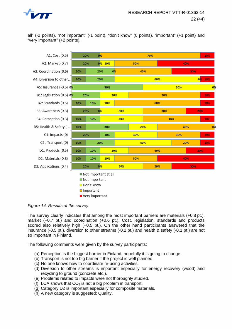
The small survey about the importance of particular barrier categories from the previoussection was carried out during the second general meeting of ReUSE project in Tampere.Total 10 participants answered the survey and the results are presented in Figure 14. Theanswers were evaluated as the average of all participants scores that was “not important at
RESEARCH REPORT VTT-R-01363-1422 (44)
all” (-2 points), “not important” (-1 point), “don’t know” (0 points), “important” (+1 point) and“very important” (+2 points).
Figure 14. Results of the survey.
The survey clearly indicates that among the most important barriers are materials (+0.8 pt.),market (+0.7 pt.) and coordination (+0.6 pt.). Cost, legislation, standards and productsscored also relatively high (+0.5 pt.). On the other hand participants answered that theinsurance (-0.5 pt.), diversion to other streams (-0.2 pt.) and health & safety (-0.1 pt.) are notso important in Finland.
The following comments were given by the survey participants:
(a) Perception is the biggest barrier in Finland, hopefully it is going to change.(b) Transport is not too big barrier if the project is well planned.(c) No one knows how to coordinate re-using activities.(d) Diversion to other streams is important especially for energy recovery (wood) and
recycling to ground (concrete etc.).(e) Problems related to impacts were not thoroughly studied.(f) LCA shows that CO2 is not a big problem in transport.(g) Category D2 is important especially for composite materials.(h) A new category is suggested: Quality.

RESEARCH REPORT VTT-R-01363-1423 (44)
7. Steel and timber building frames
The great advantage of structural steel and timber is that those materials can very easilyform a simple load-bearing frame that serves as a platform for all other components attachedto it (see Figure 15). The load-carrying function of the frame is clearly separated from thefunctions of connected elements (such as building envelope, flooring, services) and thereforethe buildings are very easy to modify and deconstruct which is very important for the re-usingprocess.
Figure 15. Example of a timber building frame (www.timberhart.com).
Such building frame can be re-used as a whole (as the Category A element), but it may bedifficult to find a suitable application for it. Therefore it would be more efficient if the buildingframe can be further decomposed into smaller parts preferably of as high category aspossible to maintain their high value. This is called clustering (see Figure 16). For examplethe steel portal frames from the industrial halls (Category B) can be re-used separately if it isnot possible to re-use the whole building.
Figure 16. Example of the clustering principle.
Steel and timber building frames can be good examples of so-called “open systemconfiguration” where all additional elements are attached directly to the basic part (thebuilding frame in our case). This brings additional advantage for re-using. Open structurescan be quickly dismantled because more deconstruction teams can work on different parts atthe same time. Reduction of deconstruction time is one of the main concerns in the decisionabout the demolition/deconstruction process.
RESEARCH REPORT VTT-R-01363-1424 (44)
7.1 Steel re-using
Steel structures have very high recycling potential. It can be roughly treated (bent, torn apart,and otherwise manhandled) and still retain its value. Even if the steel is mixed with othermaterials, it can be magnetically separated for recycling. Most of the steel scrap frombuilding demolition can be used in blast or electric furnaces for new material production.Melting, rolling and/or forming of recycled steel products, however, still consumeconsiderable amount of energy and resources, and create waste and emissions. Scrap metalhas to be collected and transported over relatively long distances to the steel mill. Re-usingbuilding component is, on the other hand, an alternative end-of-life scenario where most ofthe heavy industrial processes can be simply bypassed.
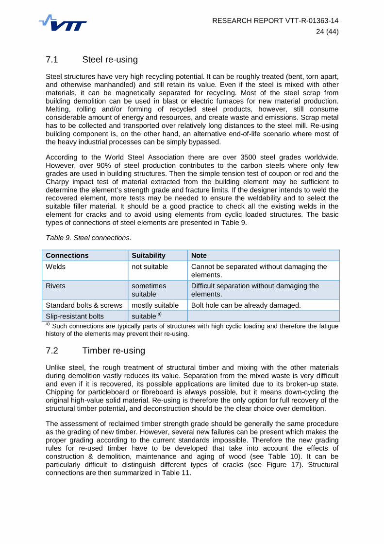
According to the World Steel Association there are over 3500 steel grades worldwide.However, over 90% of steel production contributes to the carbon steels where only fewgrades are used in building structures. Then the simple tension test of coupon or rod and theCharpy impact test of material extracted from the building element may be sufficient todetermine the element’s strength grade and fracture limits. If the designer intends to weld therecovered element, more tests may be needed to ensure the weldability and to select thesuitable filler material. It should be a good practice to check all the existing welds in theelement for cracks and to avoid using elements from cyclic loaded structures. The basictypes of connections of steel elements are presented in Table 9.
Table 9. Steel connections.
Connections Suitability NoteWelds not suitable Cannot be separated without damaging the
elements.Rivets sometimes
suitableDifficult separation without damaging theelements.
Standard bolts & screws mostly suitable Bolt hole can be already damaged.Slip-resistant bolts suitable a)
a) Such connections are typically parts of structures with high cyclic loading and therefore the fatiguehistory of the elements may prevent their re-using.
7.2 Timber re-using
Unlike steel, the rough treatment of structural timber and mixing with the other materialsduring demolition vastly reduces its value. Separation from the mixed waste is very difficultand even if it is recovered, its possible applications are limited due to its broken-up state.Chipping for particleboard or fibreboard is always possible, but it means down-cycling theoriginal high-value solid material. Re-using is therefore the only option for full recovery of thestructural timber potential, and deconstruction should be the clear choice over demolition.
The assessment of reclaimed timber strength grade should be generally the same procedureas the grading of new timber. However, several new failures can be present which makes theproper grading according to the current standards impossible. Therefore the new gradingrules for re-used timber have to be developed that take into account the effects ofconstruction & demolition, maintenance and aging of wood (see Table 10). It can beparticularly difficult to distinguish different types of cracks (see Figure 17). Structuralconnections are then summarized in Table 11.

RESEARCH REPORT VTT-R-01363-1425 (44)
Table 10. Timber damage.
Damage Importance NoteBolt holes mild reduce the cross-sectionNotches severe reduce the cross-section, cause stress
concentrationShakes (crack fromoverloading) and splits
severe require a treatment
Checks (rheological cracks) mild reduce the stiffness, increase the risk ofbiotic damage
Shape distortions mild difficult to fit into new structureBiotic damage mild to severe usually requires a treatment
Figure 17. Shakes, checks and splits [12].
Table 11. Timber connections.
Connections Suitability NoteGlued connections not suitable Cannot be separated without damaging the
elements.Carpentry joints sometimes
suitableNotches can cause stress concentration if theelements are used in different configuration.
Nails, staples sometimessuitable
Fail in bending, and therefore are difficult to removewithout damaging the element.
Screws mostly suitable The same connector is not so effective in the samehole.
Bolts, dowels suitable The hole and the cracks should be checked.

RESEARCH REPORT VTT-R-01363-1426 (44)
7.3 Case study: LCA of steel element
The following LCA study compares three cases of life-cycle environmental impact and costsof a hot-rolled steel beam with welded end-plates and bolted connections that can be easilyreused in similar structure after dismantling from the original one.
In the first scenario (recycling), a beam is produced from steel sections and plates deliveredfrom the mill, while the second case (reusing) considers reclaimed beam as an input.
OpenLCA software was used for calculation [13] together with ELCD database of European’sCommission [14] that provided basic data for steel production, transport and wasteprocessing.
7.3.1 Goal and scope
The study concentrates on declaring benefits and loads beyond the traditional systemboundary in environmental product declaration (part D of EN 15804:2012 [3]). The aim is tocalculate the difference of environmental impact and costs of two scenarios (recycling andreusing). Therefore, the whole life-cycle doesn’t have to be calculated since the constructionand use stages are the same in both cases (see Figure 21). In our example, the use stagewas totally neglected.
7.3.2 Functional unit
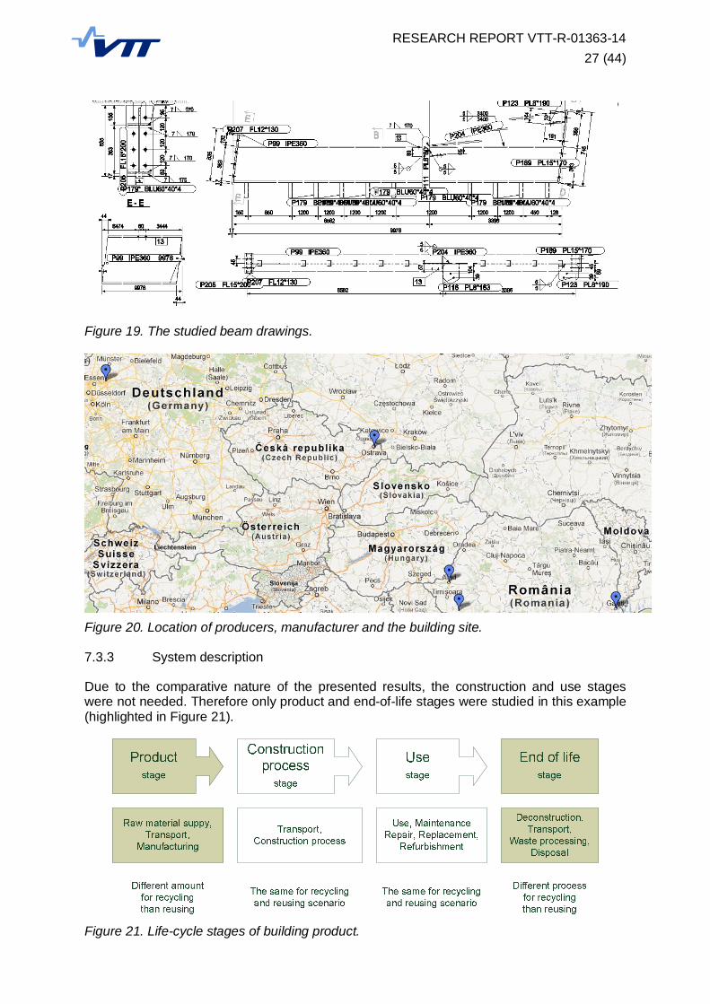
One steel beam welded from hot-rolled profile and steel plates, and connected to thestructure with preloaded bolts is a functional unit of this life-cycle study (see Figure 19). Thesame beam (822.2 kg) is referred as new (welded together), finished (painted), in structure(assembled) and used (disassembled) during the LCA study. It is part of the industrialbuilding (see Figure 18) located in Arad (Romania). However, its parts are transported fromdifferent locations (see Figure 20). Bolts are manufactured in Dortmund (Germany), steelhot-rolled sections in Ostrava (Czech Republic) and steel hot-rolled coil in Gala i (Romania).The beam is then manufactured in the workshop in Boc a (Romania). The same place will beused also for cleaning and re-manufacturing of re-used beams. For the simplicity we assumethat the new location of re-used beam will be as well in Arad.
Figure 18. Industrial building in Arad (Romania).
RESEARCH REPORT VTT-R-01363-1427 (44)
Figure 19. The studied beam drawings.
Figure 20. Location of producers, manufacturer and the building site.
7.3.3 System description
Due to the comparative nature of the presented results, the construction and use stageswere not needed. Therefore only product and end-of-life stages were studied in this example(highlighted in Figure 21).
Figure 21. Life-cycle stages of building product.
RESEARCH REPORT VTT-R-01363-1428 (44)
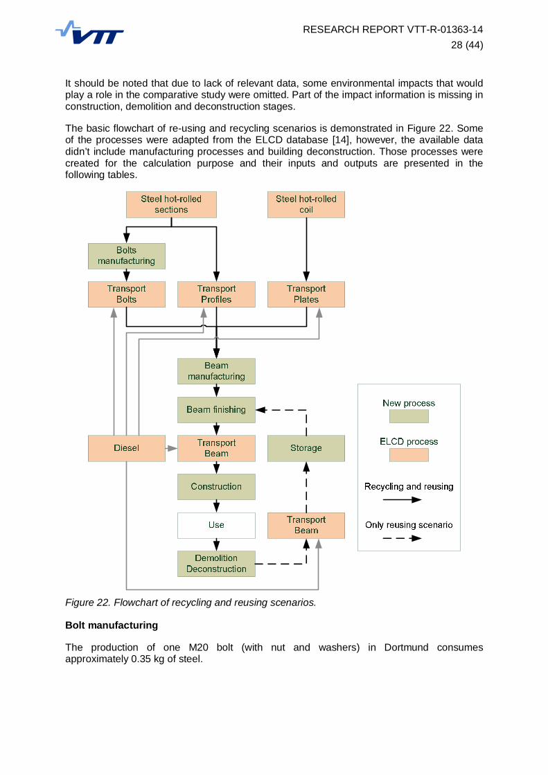
It should be noted that due to lack of relevant data, some environmental impacts that wouldplay a role in the comparative study were omitted. Part of the impact information is missing inconstruction, demolition and deconstruction stages.
The basic flowchart of re-using and recycling scenarios is demonstrated in Figure 22. Someof the processes were adapted from the ELCD database [14], however, the available datadidn’t include manufacturing processes and building deconstruction. Those processes werecreated for the calculation purpose and their inputs and outputs are presented in thefollowing tables.
Figure 22. Flowchart of recycling and reusing scenarios.
Bolt manufacturing
The production of one M20 bolt (with nut and washers) in Dortmund consumesapproximately 0.35 kg of steel.
RESEARCH REPORT VTT-R-01363-1429 (44)
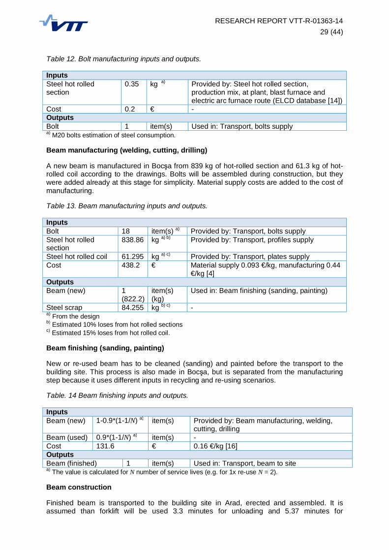
Table 12. Bolt manufacturing inputs and outputs.
InputsSteel hot rolledsection
0.35 kg a) Provided by: Steel hot rolled section,production mix, at plant, blast furnace andelectric arc furnace route (ELCD database [14])
Cost 0.2 € -OutputsBolt 1 item(s) Used in: Transport, bolts supplya) M20 bolts estimation of steel consumption.
Beam manufacturing (welding, cutting, drilling)
A new beam is manufactured in Boc a from 839 kg of hot-rolled section and 61.3 kg of hot-rolled coil according to the drawings. Bolts will be assembled during construction, but theywere added already at this stage for simplicity. Material supply costs are added to the cost ofmanufacturing.
Table 13. Beam manufacturing inputs and outputs.
InputsBolt 18 item(s) a) Provided by: Transport, bolts supplySteel hot rolledsection
838.86 kg a) b) Provided by: Transport, profiles supply
Steel hot rolled coil 61.295 kg a) c) Provided by: Transport, plates supplyCost 438.2 € Material supply 0.093 €/kg, manufacturing 0.44
€/kg [4]OutputsBeam (new) 1
(822.2)item(s)(kg)
Used in: Beam finishing (sanding, painting)
Steel scrap 84.255 kg b) c) -a) From the designb) Estimated 10% loses from hot rolled sectionsc) Estimated 15% loses from hot rolled coil.
Beam finishing (sanding, painting)
New or re-used beam has to be cleaned (sanding) and painted before the transport to thebuilding site. This process is also made in Boc a, but is separated from the manufacturingstep because it uses different inputs in recycling and re-using scenarios.
Table. 14 Beam finishing inputs and outputs.
InputsBeam (new) 1-0.9*(1-1/N) a) item(s) Provided by: Beam manufacturing, welding,
cutting, drillingBeam (used) 0.9*(1-1/N) a) item(s) -Cost 131.6 € 0.16 €/kg [16]OutputsBeam (finished) 1 item(s) Used in: Transport, beam to sitea) The value is calculated for N number of service lives (e.g. for 1x re-use N = 2).
Beam construction
Finished beam is transported to the building site in Arad, erected and assembled. It isassumed than forklift will be used 3.3 minutes for unloading and 5.37 minutes for
RESEARCH REPORT VTT-R-01363-1430 (44)
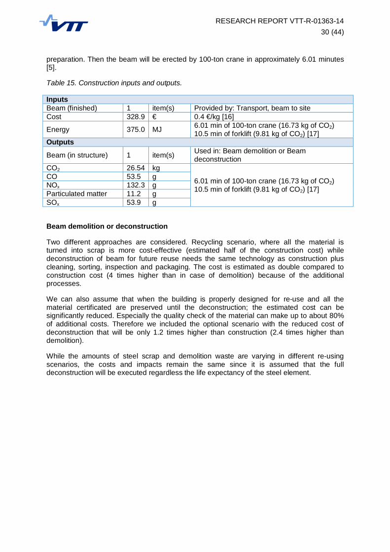
preparation. Then the beam will be erected by 100-ton crane in approximately 6.01 minutes[5].
Table 15. Construction inputs and outputs.
InputsBeam (finished) 1 item(s) Provided by: Transport, beam to siteCost 328.9 € 0.4 €/kg [16]
Energy 375.0 MJ 6.01 min of 100-ton crane (16.73 kg of CO2)10.5 min of forklift (9.81 kg of CO2) [17]
Outputs
Beam (in structure) 1 item(s) Used in: Beam demolition or Beamdeconstruction
CO2 26.54 kg
6.01 min of 100-ton crane (16.73 kg of CO2)10.5 min of forklift (9.81 kg of CO2) [17]
CO 53.5 gNOx 132.3 gParticulated matter 11.2 gSOx 53.9 g
Beam demolition or deconstruction
Two different approaches are considered. Recycling scenario, where all the material isturned into scrap is more cost-effective (estimated half of the construction cost) whiledeconstruction of beam for future reuse needs the same technology as construction pluscleaning, sorting, inspection and packaging. The cost is estimated as double compared toconstruction cost (4 times higher than in case of demolition) because of the additionalprocesses.
We can also assume that when the building is properly designed for re-use and all thematerial certificated are preserved until the deconstruction; the estimated cost can besignificantly reduced. Especially the quality check of the material can make up to about 80%of additional costs. Therefore we included the optional scenario with the reduced cost ofdeconstruction that will be only 1.2 times higher than construction (2.4 times higher thandemolition).
While the amounts of steel scrap and demolition waste are varying in different re-usingscenarios, the costs and impacts remain the same since it is assumed that the fulldeconstruction will be executed regardless the life expectancy of the steel element.

RESEARCH REPORT VTT-R-01363-1431 (44)
Table 16. Demolition and deconstruction inputs and outputs.
InputsBeam (in structure) 1 item(s) Provided by: Beam constructionCost (demolition) 164.4 € 0.20 €/kg
Cost (deconstruction) 657.8 € 0.80 €/kg394.7 € 0.48 €/kg when designed for re-use
Energy (demolition) 103.5 MJ 10 min of man-lift estimated acc. to [17]Energy (deconstruction) 375.0 MJ see beam constructionOutputs (demolition)Steel scrap 781.09 kg a) -Demolition waste 41.11 kg a) -CO2 7.32 kg
10 min of man-lift estimated acc. to [17]CO 64.2 gNOx 60.0 gParticulated matter 6.0 gSOx 14.8 gOutputs (deconstruction)
Beam (used) 0.9*(1-1/N) c) item(s) b) Used in: Transport, beamfrom site
Steel scrap 781.09*[1-0.9*(1-1/N)] c) kg a) b) -Demolition waste 41.11*[1-0.9*(1-1/N)] c) kg a) b) -CO2 26.54 kg
see beam constructionCO 53.5 gNOx 132.3 gParticulated matter 11.2 gSOx 53.9 ga) Estimated 5% waste from the recovered steel scrapb) Estimated 10% scrap from the recovered beams (every 10th beam)c) The value is calculated for N number of service lives (e.g. for 1x re-use N = 2).
Articulated lorry transport, Euro 0, 1, 2, 3, 4 mix, 40 t total load, 27 t max payload
Transport was provided as a generic process with variable cargo and distance. The basicparameters are summarized in the following tables.
Table 17. Transport inputs and outputs.
InputsCargo 1 kg a) Provided by various processesDiesel 0.00139 kg/100 km Provided by: Diesel, consumption mix, at
refinery, from crude oil, 200 ppm sulphur (ELCDdatabase [14])
OutputsCargo 1 kg a) Used in various processesAmmonia, Benzene, Carbon dioxide, Carbon monoxide, Dinitrogen monoxide, Methane,Nitrogen oxides, NMVOC, Particulates < 2.5 um, Sulphur dioxide, Toluene, Xylene b)
a) Different cargo used (Steel hot-rolled section or coil, Bolt, Beam)b) According to ELCD database [14].

RESEARCH REPORT VTT-R-01363-1432 (44)
Table 18. Transport data.
Transportprocess
Cargo Distance Cost [16]
Transport,bolts supply
Bolt(2.86 item(s) per kg)
1550 km(Dortmund - Boc a)
0.03 €/kg*100 km2.93 €/beam
Transport,profiles supply
Steel hot rolled section 850 km(Ostrava - Boc a)
0.01 €/kg*100 km7.13 €/beam
Transport,plates supply
Steel hot rolled coil 750 km(Gala i - Boc a)
0.005 €/kg*100 km0.23 €/beam
Transport,beam to site
Beam(0.00122 item(s) per kg)
150 km(Boc a - Arad)
0.005 €/kg*100 km0.62 €/beam
Transport,beam from site
Beam(0.00122 item(s) per kg)
150 km(Arad - Boc a)
0.005 €/kg*100 km0.62 €/beam
Other processes
Table 19. Other processes.
Inputs [14] OutputsSteel hot rolled coil, production mix, at plant,blast furnace route, thickness 2 to 7 mm, width600 to 2100 mm
elementary inputsaccording to ELCD
Steel hot rolled coil(+ emissions, waste)
Steel hot rolled section, production mix, atplant, blast furnace and electric arc furnaceroute
elementary inputsaccording to ELCD
Steel hot rolledsection(+ emissions, waste)
Diesel, consumption mix, at refinery, fromcrude oil, 200 ppm sulphur
elementary inputsaccording to ELCD
Diesel(+ emissions, waste)
7.3.4 Results
The basic life-cycle impact categories (GWP, ODP, AP and EP) were calculated usingCML 2001 methodology (see Table 20 and Figure 23). Moreover, the total cost of theprocesses involved in the calculation is presented in Table 20 and Figure 23. The value ofthe salvaged parts is not subtracted from the final results because it was already included inthe manufacturing phase (no cost was allocated for the used beams).
Table 20. Results of LCA study (values expressed for one beam and one building life).
LCIA category units N = 1no re-use
N = 21x re-use
N = 32x re-use
N = 43x re-use
GWP Global warmingpotential (GWP100) kg CO2 eq. 1075 901 642 454
ODP Stratospheric ozonedepletion (ODP10)
kg CFC11eq. x 10-8 4.27 4.44 3.52 2.78
AP Acidificationpotential (generic) kg SO2 eq. 3.33 2.90 2.11 1.53
EP Eutrophicationpotential (generic) kg (PO4)3- eq. 0.293 0.278 0.212 0.160
POCP Photochemicaloxidation (high NOx)
kg ethyleneeq. 0.089 0.046 0.032 0.025
Cost € 1149 1394 1312 1270Cost (designed for re-using) € 1149 1131 1048 1007
RESEARCH REPORT VTT-R-01363-1433 (44)
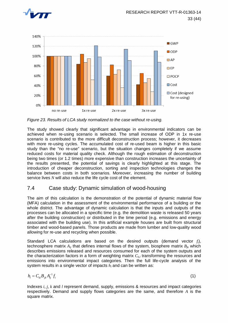
Figure 23. Results of LCA study normalized to the case without re-using.
The study showed clearly that significant advantage in environmental indicators can beachieved when re-using scenario is selected. The small increase of ODP in 1x re-usescenario is contributed to the more difficult deconstruction process; however, it decreaseswith more re-using cycles. The accumulated cost of re-used beam is higher in this basicstudy than the “no re-use” scenario, but the situation changes completely if we assumereduced costs for material quality check. Although the rough estimation of deconstructionbeing two times (or 1.2 times) more expensive than construction increases the uncertainty ofthe results presented, the potential of savings is clearly highlighted at this stage. Theintroduction of cheaper deconstruction, sorting and inspection technologies changes thebalance between costs in both scenarios. Moreover, increasing the number of buildingservice lives N will also reduce the life cycle cost of the element.
7.4 Case study: Dynamic simulation of wood-housing
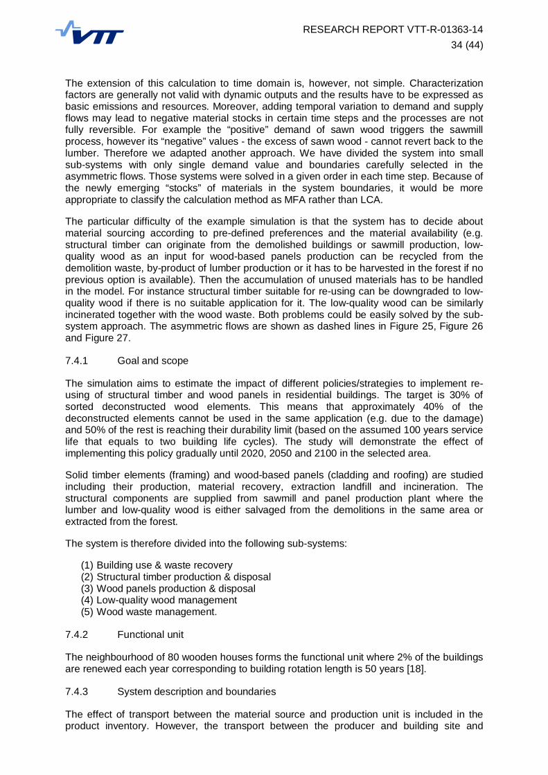
The aim of this calculation is the demonstration of the potential of dynamic material flow(MFA) calculation in the assessment of the environmental performance of a building or thewhole district. The advantage of dynamic calculation is that the inputs and outputs of theprocesses can be allocated in a specific time (e.g. the demolition waste is released 50 yearsafter the building construction) or distributed in the time period (e.g. emissions and energyassociated with the building use). In this artificial example houses are built from structuraltimber and wood-based panels. Those products are made from lumber and low-quality woodallowing for re-use and recycling when possible.
Standard LCA calculations are based on the desired outputs (demand vector fi),technosphere matrix Aij that defines internal flows of the system, biosphere matrix Bjk whichdescribes emissions released and resources consumed for each of the system outputs andthe characterization factors in a form of weighting matrix Ck,l transforming the resources andemissions into environmental impact categories. Then the full life-cycle analysis of thesystem results in a single vector of impacts hl and can be written as:
1l kl jk ij ih C B A f (1)
Indexes i, j, k and l represent demand, supply, emissions & resources and impact categoriesrespectively. Demand and supply flows categories are the same, and therefore A is thesquare matrix.
RESEARCH REPORT VTT-R-01363-1434 (44)
The extension of this calculation to time domain is, however, not simple. Characterizationfactors are generally not valid with dynamic outputs and the results have to be expressed asbasic emissions and resources. Moreover, adding temporal variation to demand and supplyflows may lead to negative material stocks in certain time steps and the processes are notfully reversible. For example the “positive” demand of sawn wood triggers the sawmillprocess, however its “negative” values - the excess of sawn wood - cannot revert back to thelumber. Therefore we adapted another approach. We have divided the system into smallsub-systems with only single demand value and boundaries carefully selected in theasymmetric flows. Those systems were solved in a given order in each time step. Because ofthe newly emerging “stocks” of materials in the system boundaries, it would be moreappropriate to classify the calculation method as MFA rather than LCA.
The particular difficulty of the example simulation is that the system has to decide aboutmaterial sourcing according to pre-defined preferences and the material availability (e.g.structural timber can originate from the demolished buildings or sawmill production, low-quality wood as an input for wood-based panels production can be recycled from thedemolition waste, by-product of lumber production or it has to be harvested in the forest if noprevious option is available). Then the accumulation of unused materials has to be handledin the model. For instance structural timber suitable for re-using can be downgraded to low-quality wood if there is no suitable application for it. The low-quality wood can be similarlyincinerated together with the wood waste. Both problems could be easily solved by the sub-system approach. The asymmetric flows are shown as dashed lines in Figure 25, Figure 26and Figure 27.
7.4.1 Goal and scope
The simulation aims to estimate the impact of different policies/strategies to implement re-using of structural timber and wood panels in residential buildings. The target is 30% ofsorted deconstructed wood elements. This means that approximately 40% of thedeconstructed elements cannot be used in the same application (e.g. due to the damage)and 50% of the rest is reaching their durability limit (based on the assumed 100 years servicelife that equals to two building life cycles). The study will demonstrate the effect ofimplementing this policy gradually until 2020, 2050 and 2100 in the selected area.
Solid timber elements (framing) and wood-based panels (cladding and roofing) are studiedincluding their production, material recovery, extraction landfill and incineration. Thestructural components are supplied from sawmill and panel production plant where thelumber and low-quality wood is either salvaged from the demolitions in the same area orextracted from the forest.
The system is therefore divided into the following sub-systems:
(1) Building use & waste recovery(2) Structural timber production & disposal(3) Wood panels production & disposal(4) Low-quality wood management(5) Wood waste management.
7.4.2 Functional unit
The neighbourhood of 80 wooden houses forms the functional unit where 2% of the buildingsare renewed each year corresponding to building rotation length is 50 years [18].
7.4.3 System description and boundaries
The effect of transport between the material source and production unit is included in theproduct inventory. However, the transport between the producer and building site and
RESEARCH REPORT VTT-R-01363-1435 (44)
between the building site and incineration plant or landfill is not considered in the study.Because of the comparative nature of the calculation, these stages will have negligible effecton the overall results. For the simplicity it is assumed that the removed components will beeither instantly re-used in the same neighbourhood, downgraded to low-quality wood orincinerated without storing.
No LCIA methodology is used because the lack of characterization factors for dynamic LCA.The results are expressed as cumulative or yearly CO2 balance. Part of the energyconsumption and production of NOX and SO2 is also calculated but not used in the resultinterpretation.
Sub-system 1: Building use & waste recovery
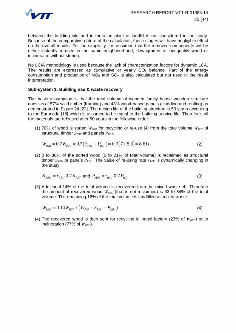
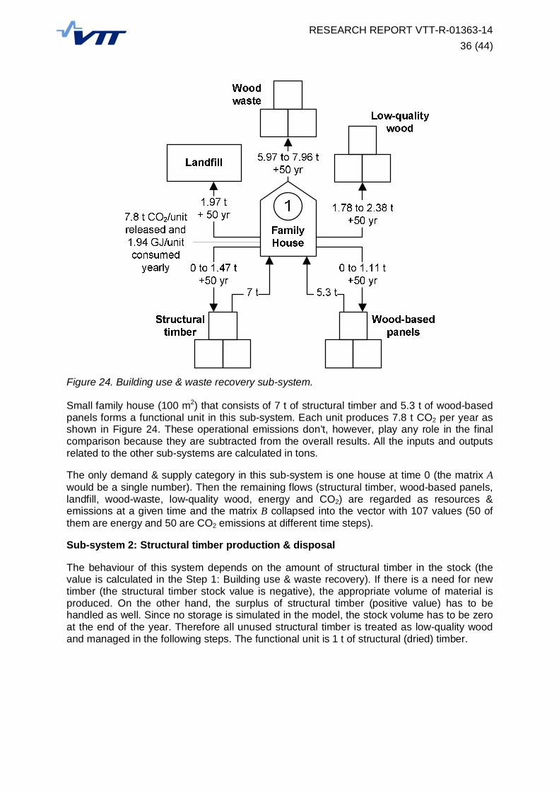
The basic assumption is that the total volume of wooden family house wooden structureconsists of 57% solid timber (framing) and 43% wood-based panels (cladding and roofing) asdemonstrated in Figure 24 [22]. The design life of the building structure is 50 years accordingto the Eurocode [18] which is assumed to be equal to the building service life. Therefore, allthe materials are released after 50 years in the following order:
(1) 70% of wood is sorted WSOR for recycling or re-use [4] from the total volume WTOT ofstructural timber STOT and panels PTOT.
0.7 0.7 0.7 7 5.3 8.61SOR TOT TOT TOTW W S P t (2)
(2) 0 to 30% of the sorted wood (0 to 21% of total volume) is reclaimed as structuraltimber SREU or panels PREU. The value of re-using rate rREU is dynamically changing inthe study.
TOTREUREU SrS 7.0 and 0.7REU REU TOTP r P (3)
(3) Additional 14% of the total volume is recovered from the mixed waste [4]. Thereforethe amount of recovered wood WREC (that is not reclaimed) is 63 to 84% of the totalvolume. The remaining 16% of the total volume is landfilled as mixed waste.
0.14REC TOT SOR REU REUW W W S P (4)
(4) The recovered wood is then sent for recycling in panel factory (23% of WREC) or toincineration (77% of WREC).
RESEARCH REPORT VTT-R-01363-1436 (44)
Figure 24. Building use & waste recovery sub-system.
Small family house (100 m2) that consists of 7 t of structural timber and 5.3 t of wood-basedpanels forms a functional unit in this sub-system. Each unit produces 7.8 t CO2 per year asshown in Figure 24. These operational emissions don’t, however, play any role in the finalcomparison because they are subtracted from the overall results. All the inputs and outputsrelated to the other sub-systems are calculated in tons.
The only demand & supply category in this sub-system is one house at time 0 (the matrix Awould be a single number). Then the remaining flows (structural timber, wood-based panels,landfill, wood-waste, low-quality wood, energy and CO2) are regarded as resources &emissions at a given time and the matrix B collapsed into the vector with 107 values (50 ofthem are energy and 50 are CO2 emissions at different time steps).
Sub-system 2: Structural timber production & disposal
The behaviour of this system depends on the amount of structural timber in the stock (thevalue is calculated in the Step 1: Building use & waste recovery). If there is a need for newtimber (the structural timber stock value is negative), the appropriate volume of material isproduced. On the other hand, the surplus of structural timber (positive value) has to behandled as well. Since no storage is simulated in the model, the stock volume has to be zeroat the end of the year. Therefore all unused structural timber is treated as low-quality woodand managed in the following steps. The functional unit is 1 t of structural (dried) timber.
RESEARCH REPORT VTT-R-01363-1437 (44)
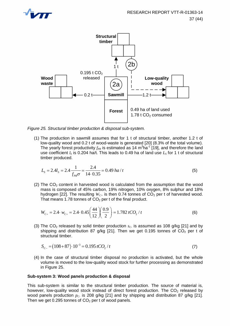
Figure 25. Structural timber production & disposal sub-system.
(1) The production in sawmill assumes that for 1 t of structural timber, another 1.2 t oflow-quality wood and 0.2 t of wood-waste is generated [20] (8.3% of the total volume).The yearly forest productivity fPR is estimated as 14 m3ha-1 [19], and therefore the landuse coefficient lS is 0.204 ha/t. This leads to 0.49 ha of land use LS for 1 t of structuraltimber produced.
1 2.42.4 2.4 0.49 /14 0.35S S
PR
L l ha tf
(5)
(2) The CO2 content in harvested wood is calculated from the assumption that the woodmass is composed of 45% carbon, 19% nitrogen, 10% oxygen, 8% sulphur and 18%hydrogen [22]. The resulting WC+ is then 0.74 tonnes of CO2 per t of harvested wood.That means 1.78 tonnes of CO2 per t of the final product.
244 0.92.4 2.4 0.45 1.782 /12 2C CW w tCO t (6)
(3) The CO2 released by solid timber production sC- is assumed as 108 g/kg [21] and byshipping and distribution 87 g/kg [21]. Then we get 0.195 tonnes of CO2 per t ofstructural timber.
32108 87 10 0.195 /CS tCO t (7)
(4) In the case of structural timber disposal no production is activated, but the wholevolume is moved to the low-quality wood stock for further processing as demonstratedin Figure 25.
Sub-system 3: Wood panels production & disposal
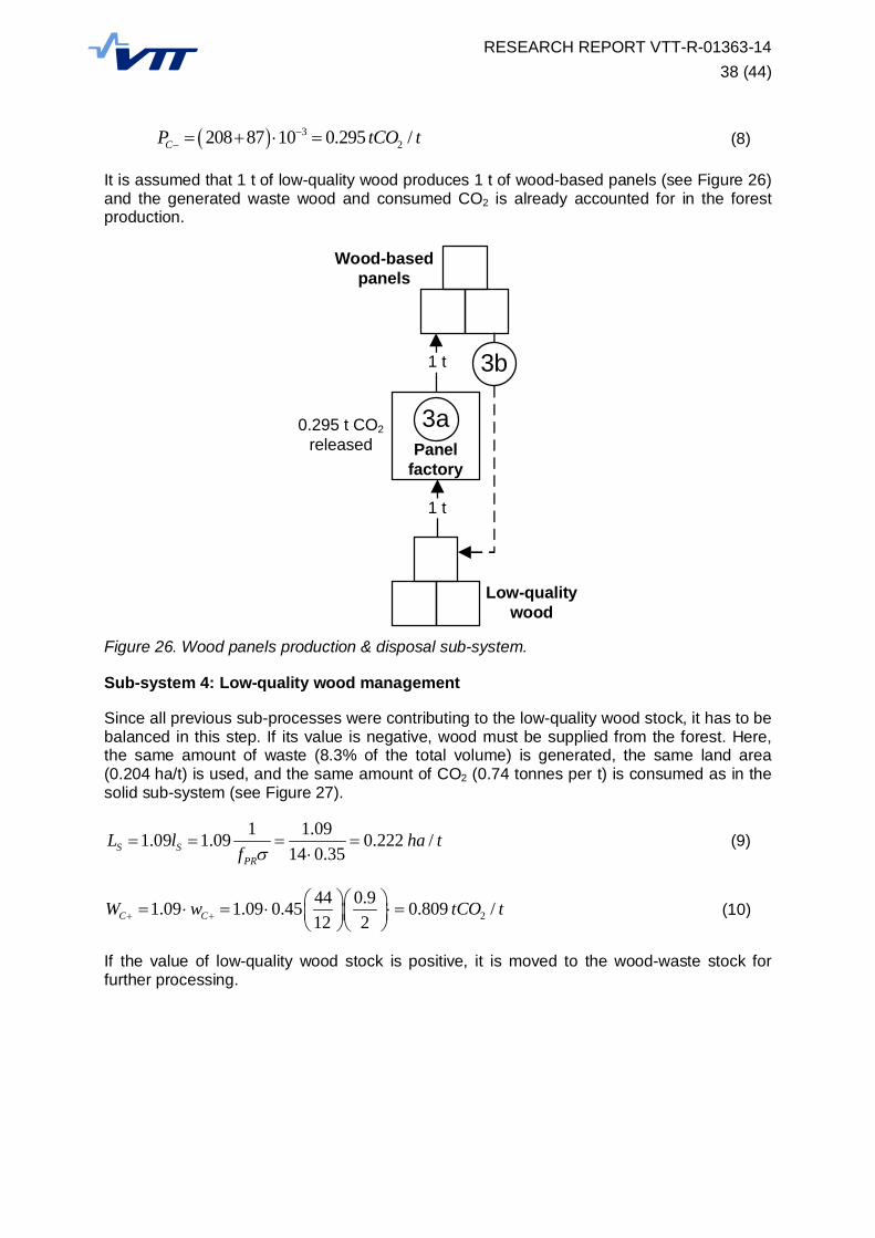
This sub-system is similar to the structural timber production. The source of material is,however, low-quality wood stock instead of direct forest production. The CO2 released bywood panels production pC- is 208 g/kg [21] and by shipping and distribution 87 g/kg [21].Then we get 0.295 tonnes of CO2 per t of wood panels.
1 t
1.2 t
2aSawmill
Forest
2b
0.49 ha of land used
0.195 t CO2released
1.78 t CO2 consumed
0.2 t
Woodwaste
Structuraltimber
Low-qualitywood
RESEARCH REPORT VTT-R-01363-1438 (44)
32208 87 10 0.295 /CP tCO t (8)
It is assumed that 1 t of low-quality wood produces 1 t of wood-based panels (see Figure 26)and the generated waste wood and consumed CO2 is already accounted for in the forestproduction.
Figure 26. Wood panels production & disposal sub-system.
Sub-system 4: Low-quality wood management
Since all previous sub-processes were contributing to the low-quality wood stock, it has to bebalanced in this step. If its value is negative, wood must be supplied from the forest. Here,the same amount of waste (8.3% of the total volume) is generated, the same land area(0.204 ha/t) is used, and the same amount of CO2 (0.74 tonnes per t) is consumed as in thesolid sub-system (see Figure 27).
1 1.091.09 1.09 0.222 /14 0.35S S
PR
L l ha tf
(9)
244 0.91.09 1.09 0.45 0.809 /12 2C CW w tCO t (10)
If the value of low-quality wood stock is positive, it is moved to the wood-waste stock forfurther processing.
Low-qualitywood
Wood-basedpanels
1 t
3aPanel
factory
3b
1 t
0.295 t CO2released
RESEARCH REPORT VTT-R-01363-1439 (44)
Figure 27. Low-quality wood management sub-system.
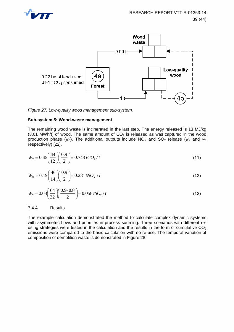
Sub-system 5: Wood-waste management
The remaining wood waste is incinerated in the last step. The energy released is 13 MJ/kg(3.61 MWh/t) of wood. The same amount of CO2 is released as was captured in the woodproduction phase (wC). The additional outputs include NOX and SO2 release (wN and wS
respectively) [22].
244 0.90.45 0.743 /12 2CW tCO t (11)
46 0.90.19 0.281 /14 2N XW tNO t (12)
264 0.9 0.80.08 0.058 /32 2SW tSO t (13)
7.4.4 Results
The example calculation demonstrated the method to calculate complex dynamic systemswith asymmetric flows and priorities in process sourcing. Three scenarios with different re-using strategies were tested in the calculation and the results in the form of cumulative CO2emissions were compared to the basic calculation with no re-use. The temporal variation ofcomposition of demolition waste is demonstrated in Figure 28.

RESEARCH REPORT VTT-R-01363-1440 (44)
Figure 28. Demolition waste in three studied scenarios.
As can be seen from the Figure 29, significant savings of CO2 can be achieved when there-using strategy is applied early. However, it should be noted that the savings are only avery small fraction of the total CO2 produced in the area (thousands of tonnes of CO2) mostlydue to the building use. Addressing the savings in operational emissions is out of the scopeof this report, but the reduction of these impacts is also expected in the future.
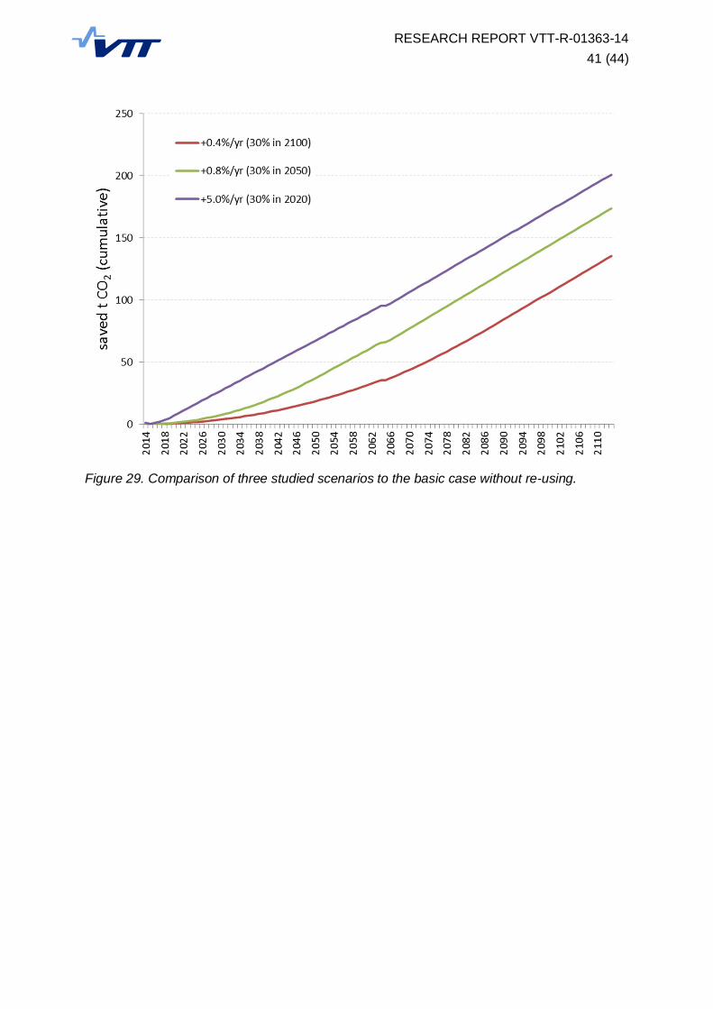
RESEARCH REPORT VTT-R-01363-1441 (44)
Figure 29. Comparison of three studied scenarios to the basic case without re-using.
RESEARCH REPORT VTT-R-01363-1442 (44)
8. Conclusions
The building element re-use practices differ with the size and complexity of the reclaimedparts. Therefore we have established 5 categories of building structural elements that can bere-used. The smaller ones (Categories D and E) tend to be re-used in more organized way,collected in the salvage yards and re-sold as basic material in the local community. On theother hand, larger and complex structural systems (Categories B and C) have higher value,but lower applicability, and therefore a different approach should be selected for their re-use.The online marketing, component labelling and BIMs are the technologies that are feasiblefor increasing the efficiency of such components re-using. The special category isCategory A (the whole building structures). Since the re-using of the whole building shouldbe rather called “building relocation”, the quality control of each element and the whole re-designing procedure is usually not required.
Re-using of building components is generally one of the most environmentally friendly end-of-life scenarios of the building provided that the durability of the components extends the lifeof the building and there is a suitable application for it. Re-suing benefits can be nowadaysdeclared in a standardized way [15]. Many environmental certification systems recognize re-using in their assessment process, however, the contribution of material and resourceefficiency to the overall score is usually very low.
There are many other practical barriers to the building components re-using that should beaddressed. One is the lack of strength grading rules for materials in re-used elements. Thismeans that re-usable load-bearing components are forced to be applied for non-structuralpurpose unless they are thoroughly tested in one of few certified laboratories in Finland.
Another barrier is the difficult deconstruction of existing buildings. The extended time andhigh demands on manual labour is usually increasing the cost of the whole process. This canbe partly improved by applying standardized deconstruction practices, proper staff trainingand using selected technologies for deconstruction. However, the greatest impact on thebuilding re-usability is in its design stage. Therefore we recommend addressing this issue inthe planning of future steps towards resource efficiency.
The standardization process and the recent changes in the environmental certificationsystems indicate that the importance of life-cycle assessment of buildings and componentswill rise in the near future. However, the LCA study of the steel element showed that there isa lack of reliable LCA data for the most critical stages in re-use such as deconstruction,sorting, quality check and re-distribution of materials and components. These gaps in life-cycle inventory databases have to be addressed in the future.
We also recommend the amendment to the waste directive [2] (a) to include wasteprevention in the 70% of (at least) recovered waste goal by 2020 in article 11, paragraph 2and (b) to include objects that are re-used for different purpose without becoming waste inarticle 3, definition of “re-use”.

RESEARCH REPORT VTT-R-01363-1443 (44)
References
[1] Bio Intelligence Service, Final report on Management of Construction and DemolitionWaste to the European Commission (DG-ENV), 2011.
[2] Directive 2008/98/EC of the European Parliament and of the Council on waste,Brussels, 2008.
[3] Decision 2000/532/EC of the European Commission establishing a list of hazardouswaste, Brussels, 2000.
[4] Communication 2011/571/EC from the Commission to the European Parliament, theCouncil, the European Economic and Social Committee and the Committee of theRegions: Roadmap to a Resource Efficient Europe, Brussels, 2011.
[5] Meinander, M., Mroueh U-M. (Eds.), Directions of future developments in wasterecycling, VTT Technology 60, VTT, Espoo, 2012.
[6] Waste Act 646/2011 of the Ministry of the Environment, Finland, 2011.
[7] Portal power company website accessed at http://www.portal-power.co.uk/, 2013.
[8] Timberhart Woodworks website accessed at http://www.timberhart.com/, 2013.
[9] Eurostat Material Flows accessed at http://appsso.eurostat.ec.europa.eu/, 2013.
[10] Heincke, C., Olsson, D., Simply Green: A quick guide to environmental and energycertification systems for sustainable buildings, Swegon Air Academy, Kvänum, 2012.
[11] Schmidt, A. Analysis of five approaches to environmental assessment of buildingcomponents in a whole building context, FORCE Technology, Applied EnvironmentalAssessment, Lynhby, 2012.
[12] FWPA Interim Industry Standard: Recycled Timber - Visually Graded RecycledDecorative Products, Melbourne, 2008.
[13] Modular Open Source Software for Sustainability Assesment accessed athttp://www.openlca.org, 2013.
[14] European Commission’s ELCD Database accessed athttp://lca.jrc.ec.europa.eu/lcainfohub, 2013.
[15] EN 15804, Sustainability of construction works - Environmental product declarations -Core rules for the product category of construction products, CEN, Brussels, 2012.
[16] Prefabricated Steel Structures for Low-Rise Building in Seismic Areas, Final report ofRFCS project PRECASTEEL.
[17] Haney, H., Environmental emmissions and energy use from the structural steelerection process: A case study, Master’s thesis, Colorado State University, Colorado,2011.
[18] EN 1990, Eurocode 0: Basis of structural design, CEN, Brussels, 2006.
[19] Moore, J., Wood properties and uses of Sitka spruce in Britain, Research report,Forestry Commission, Edinburgh, 2011.
[20] Herzog, T., Natterer, J., Schweitzer, R., Volz, M., Winter, W., Timber constructionmanual, 4th ed., Birghäuser Verlag AG, Berlin, 2004.

RESEARCH REPORT VTT-R-01363-1444 (44)
[21] Kuittinen, M., Ludwig, A., Weiss, G. (Eds.) Wood in carbon efficient construction: Tools,methods and applications, Finland, 2013.
[22] Bajpai e al., A comparative Life Cycle Assessment of a wooden house and a brickhouse.