Embed Size (px)
Citation preview

INSTRUCTION MANUAL
BARRACUDA 200ZWPORTABLE WALKING FOOT SEWING MACHINE


THE BARRACUDA 200ZWPORTABLE WALKING FOOT SEWING MACHINE INSTRUCTION MANUAL
MATERIAL IS OWNED BY RELIABLE AND MAY NOT BE
REPRODUCED IN WHOLE OR IN PART WITHOUT EXPRESS
WRITTEN PERMISSION FROM RELIABLE CORPORATION
COPYRIGHT 2016 RELIABLE CORPORATION

PREFACE
The Reliable Barracuda 200ZW zig-zag and straight stitch portable walking-foot machine is remarkably versatile. Designed for boat owners, hobbyists, and small businesses, the Barracuda is ideal for medium-to-heavy-weight sewing jobs.
SMALL SIZE, BIG PERFORMANCE
With a stitch quality comparable to an industrial machine, there’s no job too big for the Barracuda. With top and bottom feeding, it produces a perfect, even stitch, even when sewing over challenging materials.

TABLE OF CONTENTS
Machine speed ...............................................................................................
Oiling ...............................................................................................................
Needle .............................................................................................................
Thread .............................................................................................................
Bobbin winding ..............................................................................................
Threading the machine and needle ...........................................................
Prepare for sewing ........................................................................................
To start sewing ..............................................................................................
To regulate the length of stitch ..................................................................
Reverse sewing ..............................................................................................
Adjusting the tension ...................................................................................
To remove the hook and clean the race ....................................................
Clutch washer/screw-assembly instructions ...........................................
Constructional drawing ................................................................................
External group ...............................................................................................
External group parts list ..............................................................................
Sewing transmission group .........................................................................
Sewing transmission group parts list ........................................................
Shuttle transmission group .........................................................................
Shuttle transmission group parts list .......................................................
Feed transmission group .............................................................................
Feed transmission group parts list ............................................................
Driving & reversing mechanism group ......................................................
Driving & reversing mechanism group parts list .....................................
Electric power & dynamic transmission group ........................................
Electric power & dynamic transmission group parts list ......................
ZigZag mechanism group ...........................................................................
ZigZag mechanism group parts list ..........................................................
To regulate zigzag width and needle position..........................................
Base plate & working plate .........................................................................
Base plate & working plate parts list ........................................................
Cuda crank installation ................................................................................
Optional – Cuda case ....................................................................................
1
1
2
2
3
4
5
5
6
6
7
8
9
10
11
12
13
14
15
16
17
18
19
20
21
22
23
24
24
25
26
27
29

SPEED OF MACHINE
The maximum speed recommended for this machine is 900 RPM or “stitches per minute”. Use regular house-hold circuit 115 Volts, 60 HZ. The machine is equipped with a one tenth (1/10) HP motor with reduction pulley to provide good power at the recom-mended speed.
This sewing machine can be mounted on a commercial stand. To do so, requires a special cut-out table top, a one inch (1 ˝) diameter pulley, a special Balance Wheel Item No. 11, and a maximum 1725 RPM motor.
OILING
Before operating , oil all “metal to metal” working parts, and at the places indicated on diagrams below. Use only genuine sewing machine oil. Operate the machine briefly on scrap material after oiling to prevent soiling the work. Frequent oiling is recommended.
01

NEEDLE
Use 135x17 needles size 10 to 23. Use size 22 for most medium to heavy sewing.
Install needle as illustrated.
THREAD
To obtain the best results with your sewing machine, we recommend size 69 Bonded Nylon Thread.
GROOVE
02

WINDING THE BOBBIN
3
4
2
5
1
03

THREADING THE MACHINE AND NEEDLE
3
6
4
5
2
1
7
8
6
5
04

PREPARE FOR SEWING
Thread the machine. Then pick up the bobbin thread as follows:
1. While holding the loose end of the needle thread in your left hand, turn the balance wheel toward you by hand until the needle moves down and up again to its highest point.
2. Pull the needle thread gently, and the bobbin thread will come up with it in the form of a loop through the needle hole.
3. With your finger, pull this loop until the end of the thread appears. If the bobbin thread does not rise, check to see if al least 5 or 6 inches of bobbin thread is hang-ing loosely from the bobbin case.
TO START SEWING
1. Place the material to be sewn under the presser feet and lower them onto the material.
2. Hold the upper or needle thread (threaded through the eye of the needle) with the fingers of the left hand. Turn (he balance wheel toward you with your right hand until the outside presser foot reaches its most backward position .
3. Now operate the foot control to start sewing.
The above procedure is necessary so the motor will start the machine to sewing. Do not help the feeding of the machine by hand, as this may bend or break the needle. Also, damage to the hook can occur.
The machine may run a little slow when it’s new. However, it will begin to “free up” and run smoothly with continued use.
During operation, the balance wheel of the machine always turns toward the operator. To avoid tangled thread and jamming of the sewing hook, do not turn the balance wheel backward (away from the operator).
WARNING: Never operate the machine without material under the presser feet. Your machine will probably “lock” and cannot be operated until the thread is cleaned out of the hook race.
05

TO REGULATE THE LENGTH OF STITCH
Most sewing will be done with the maximum stitch length. However, the length of the stitch can be adjusted as follows:
1. Loosen the thumb nut on the stitch length lever.
2. Raise the stitch length (feed regulator) lever until the desired stitch length is obtained.
3. Tighten the thumb nut.
REVERSE SEWING
To sew in reverse:
1. Lower the feed regulator (stitch length) lever all the way to the bottom of the slot in the stitch length plate.
2. Hold the lever there until reverse sewing is completed.
3. Then return the lever the forward position.
6
5
4
3
2
1
0
FORWARD FEED
REVERSE FEED
06
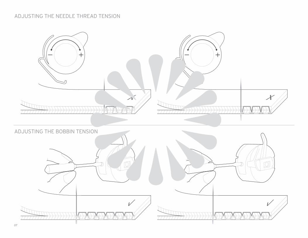
ADJUSTING THE NEEDLE THREAD TENSION
ADJUSTING THE BOBBIN TENSION
07
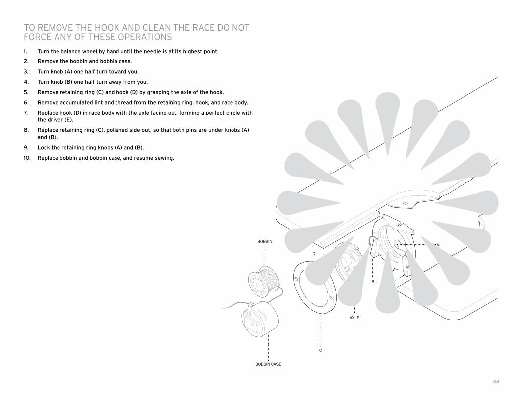
TO REMOVE THE HOOK AND CLEAN THE RACE DO NOT FORCE ANY OF THESE OPERATIONS
1. Turn the balance wheel by hand until the needle is at its highest point.
2. Remove the bobbin and bobbin case.
3. Turn knob (A) one half turn toward you.
4. Turn knob (B) one half turn away from you.
5. Remove retaining ring (C) and hook (D) by grasping the axle of the hook.
6. Remove accumulated lint and thread from the retaining ring, hook, and race body.
7. Replace hook (D) in race body with the axle facing out, forming a perfect circle with the driver (E).
8. Replace retaining ring (C). polished side out, so that both pins are under knobs (A) and (B).
9. Lock the retaining ring knobs (A) and (B).
10. Replace bobbin and bobbin case, and resume sewing.
BOBBIN
BOBBIN CASE
C
AXLE
B
D
A
E
08

CLUTCH WASHER/SCREW-ASSEMBLY INSTRUCTIONS
1. Remove clutch stop screw.
2. Remove hand clutch screw.
3. Notice position of prongs on clutch washer in slot of balance wheel bushing.
4. Remove clutch washer and make 1/2 turn and replace.
5. Screw in hand clutch screw very light
6. Screw in stop screw.
7. Back off on hand clutch screw.
8. Run motor and check to see if balance wheel turns freely without running the machine.
9. Tighten hand clutch screw and the machine should run properly.
BALANCE WHEEL CLUTCH WASHER CLUTCH STOP SCREW
CLUTCH WASHER
PRONGS ON CLUTCH WASHER POINT OUT. WILL NOT WORK IF POINTED IN.
HAND CLUTCH SCREW
SLOT IN BUSHING
09

CONSTRUCTIONAL
10

22
28
18
19
19
30
31
31
20
18-1
7
14 13
12
12
2524
27
17
23
176
8
7
2
3
9
26
56
6
4
12
11
29
21
10
15
16
16
GROUP 1 CONSTRUCTION EXTERNAL GROUP
11
1

KEY NO.
1
2
3
4
5
6
7
8
9
10
11
12
13
14
15
16
KEY NO.
17
18
19
20
21
22
23
24
25
26
27
28
29
30
31
18-1
PART NO.
W047
B071
EO66
E066-2
W047-1
A092
E070-1
E070
W047-2
WOO1
WOO2
D097
W048
C097
W125
A075
PART NO.
B010
W032
A052
A048-B
W029
W184-1
W030
W025
W025-1
E072
A117
W184-3
W184-2
A049
AO5O
W032-1
Q’TY
1
1
1
1
1
1 2
1
1
1
1
1
2 1
1
2
1
1
Q’TY
2
1
2
1
1
1
1
1
2
1
1
1
1
1
1
1
PART NAME
TOP PLATE
TOP PLATE SET SCREW
BOBBIN WINDER STOPPER
BOBBIN WINDER STOPPER SET SCREW
SMALL PLATE COVER
SMALL PLATE COVER SET SCREW BOBBIN WINDER ASSEMBLY SET SCREW
BOBBIN WINDER TENSION ASSEMBLY SET NUT
BOBBIN WINDER TENSION ASSEMBLY
SPOOL PIN
ARM BODY
BED
NEEDLE BAR SUPPORT SET SCREW THREE HOLE THREAD GUIDE SET SCREW
FACE PLATE
FACE PLATE SET SCREW
STITCH LENGTH PLATE
STITCH LENGTH PLATE SET SCREW
PART NAME
BOBBIN WINDER SET SCREW
NEEDLE PLATE
NEEDLE PLATE SET SCREW
SHUTTLE RACE SLIDE
THREE HOLE THREAD GUIDE
DIAL TENSION ASSEMBLY
BOBBIN WINDER
CRANK ROO BEARING SET BASE
CRANK ROD BEARING SET BASE SET SCREW
TOP PLATE SET SCREW
BOBBIN WINDER RUBBER RING
THREAD TAKE-UP/CHECK-SPRING
TENSION RELEASE PIN
SHUTTLE RACE SLIDE SPRING
SHUTTLE RACE SLIDE SPRING SET SCREW
ZIG ZAG NEEDLE PLATE
GROUP 1
12
17
11
1
2
3
8
384
7
37
27
12
4
26
13
25
19
27
28
35
18
16
24
10
9
6 5
14
23
16
15
21
20
31
2230
34
32
29
33
4
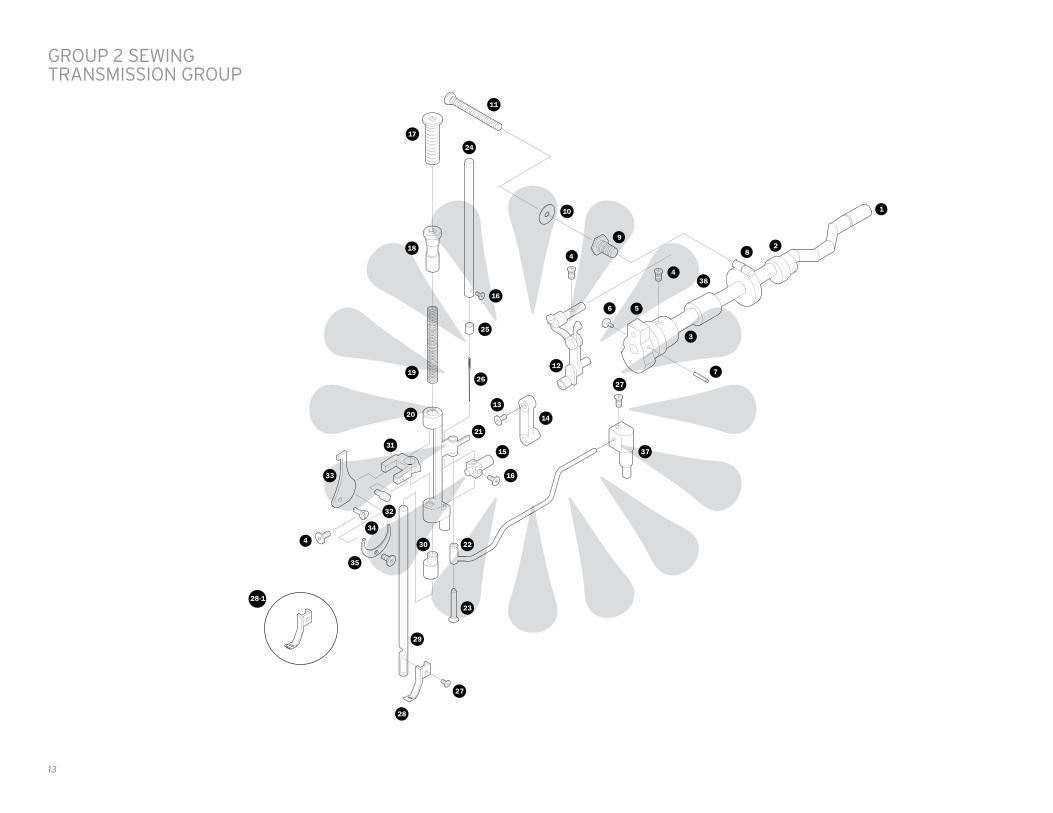
GROUP 2 SEWING TRANSMISSION GROUP
28-1
13

KEY NO.
1
2
3
4
5
6
7
8
9
10
11
12
13
14
15
16
17
18
19
20
KEY NO.
21
22
23
24
25
26
27
28
28-1
29
30
31
32
33
34
35
36
37
38
PART NO.
E053
B007
B051
A012
B048
A029
E048-1
W028-4
W028-2
W028-3
W028-1
E020
E02O-2
B018
A042
A092
A031
WO10
A032
B016
PART NO.
A021
W015
B099
WO66
WO67
W008
A036
W012
B043-1
A035-1
B028
W039
A046
W043
D020
W045
8046
W016
WO65
Q’TY
1
2
1
1 1 1
1
1
1
1
1
1
1
1
1
1
1
1
1
1
1
1
Q’TY
1
1
1
1
1
1
1
1
1
1
1
1
1
1
1
1
1
1
1
PART NAME
ARM SHAFT
FEED CAM
ARM SHAFT BUSHING
THREAD TAKE-UP ASSEMBLY SET SCREW ARM SHAFT BUSHING SET SCREW TENSION RELEASE LEVER DRAG LINK PIN SET SCREW
THREAD TAKE-UP LEVER CAM
THREAD TAKE-UP ASSEMBLY SET SCREW
THREAD TAKE-UP LEVER CAM SET PIN
CRANK ROD LEVER CAM FOLLOWER
CRANK ROD LEVER CAM FOLLOWER ADJUST NUT
CRANK ROD LEVER CAM FOLLOWER LOCK SCREW
CRANK RO D LEVER CAM FOLLOWER LOCK NUT
THREAD TAKE-UP ASSEMBLY
NEEDLE BAR CONNECTING ROD SET SCREW
NEEDLE BAR CONNECTING ROD
NEEDLE BAR CONNECTING STUD
NEEDLE SET SCREW
PRESSER REGULATING THUMB SCREW
PRESSER REGULATING THUMB SET SCREW
PRESSER BAR SPRING
NEEDLE BAR SUPPORT
PART NAME
NEEDLE BAR CONNECTING JOINT SET SCREW
ZIGZAG CONNECTING ROD
NEEDLE BAR CONNECTING JOINT PIN
NEEDLE BAR
NEEDLE THREAD GUIDE
NEEDLE
PRESSER FOOT SET SCREW
INSIDE PRESSER FOOT
ZIG ZAG PRESSER FOOT
PRESSER BAR
PRESSER BAR LOWER BUSHING
PRESSER BAR BRACKET
PRESSER BAR ACTUATOR GUIDE SCREW
TENSION RELEASE LEVER DRAG LINK
TENSION RELEASE LEVER DRAG LINK SET PIN
TENSION RELEASE LEVER
TENSION RELEASE LEVER SET SCREW
ZIGZAG CONNECTING ROD SET BASE
PRESSER BAR ACTUATOR “CAM”
GROUP 2
14

13
6
15
14
16
17
4
3
5 4
2
1
19
19
18
109
9
11
12 20
7
8
6
GROUP 3 SHUTTLE TRANSMISSION GROUP
15

KEY NO.
1
2
3
4
5
6
7
8
9
10
11
12
13
14
15
16
17
18
19
20
PART NO.
B139
A027B
A0278
A023
A024
A018
A021
B179
B177
B155
A084
B153
B170
B172
Wl72
D099
A107
D100
B139-2
B177-1
Q’TY
1
1
1
2
1
1 1
1
1
2
1
1
1
1
1
1
1
1
1
2
4
PART NAME
CRANK CONNECTING ROD
CRANK CONNECTING ROD SET SCREW
CRANK CONNECTING ROD SET NUT
OSCILLATING SHAFT SET SCREW & NUT
OSCILLATING SHAFT
SHUTTLE DRIVER PIN OSCILLATING SHAFT CRANK SET PIN
OSCILLATING SHAFT CRANK SET SCREW
OSCILLATING SHAFT CRANK. WITH SLIDE BLOCK
LOWER SHAFT COLLAR
SHUTTLE RACE GUIDE
SHUTTLE RACE GUIDE SHAFT
SHUTTLE RACE GUIDE SHAFT SET SCREW
SHUTTLE RACE GUIDE SHAFT COMPLETE
LOWER SHAFT
SHUTTLE DRIVER
SHUTTLE HOOK
BOBBIN
BOBBIN CASE ASSEMBLY
CRANK CONNECTING ROD CAP SET SCREW
LOWER SHAFT COLLAR SET SCREW
GROUP 3
16

9
8
10
11
13
18
15
17
17-1
15
16
11
11
23
22
19
14
11
21
20
12 1
2
3
5
24
76
4
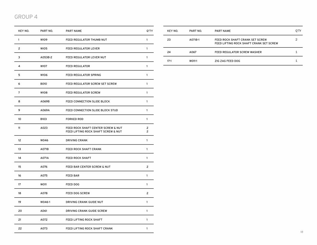
GROUP 4 FEED TRANSMISSION GROUP
17
KEY NO.
1
2
3
4
5
6
7
8
9
10
11
12
13
14
15
16
17
18
19
20
21
22
KEY NO.
23
24
17-1
PART NO.
W109
WIO5
A053B-2
W107
W1O6
B010
W108
A069B
A069A
B103
A023
W046
A071B
A071A
A076
A075
WO11
A078
W046-1
AD61
A072
A073
PART NO.
A07IB-1
A067
W011·1
Q’TY
1
1
1
1
1
1
1
1
1
1
2 2
1
1
1
2
1
1
2
1
1
1
1
Q’TY
2
1
1
PART NAME
FEED REGULATOR THUMB NUT
FEED REGULATOR LEVER
FEED REGULATOR LEVER NUT
FEED REGULATOR
FEED REGULATOR SPRING
FEED REGULATOR SCREW SET SCREW
FEED REGULATOR SCREW
FEED CONNECTION SLIDE BLOCK
FEED CONNECTION SLIDE BLOCK STUD
FORKED ROD
FEED ROCK SHAFT CENTER SCREW & NUT FEED LIFTING ROCK SHAFT SCREW & NUT
DRIVING CRANK
FEED ROCK SHAFT CRANK
FEED ROCK SHAFT
FEED BAR CENTER SCREW & NUT
FEED BAR
FEED DOG
FEED DOG SCREW
DRIVING CRANK GUIDE NUT
DRIVING CRANK GUIDE SCREW
FEED LIFTING ROCK SHAFT
FEED LIFTING ROCK SHAFT CRANK
PART NAME
FEED ROCK SHAFT CRANK SET SCREW FEED LIFTING ROCK SHAFT CRANK SET SCREW
FEED REGULATOR SCREW WASHER
ZIG ZAG FEED DOG
GROUP 4
18

16 17
15
1614
18
26
12
118
7
24
23
25
6
4
35
1
2
22
21
38
34
38
37
35
3633
37
38
32
31
32
38
42
41
40
39
30
30
29
28
2729
19
20
9
10
1013
GROUP 5 DRIVING & REVERSING MECHANISM GROUP
17-1
19

KEY NO.
24
25
26
27
28
29
30
31
32
33
34
35
36
37
38
39
40
41
42
17-1
PART NO.
W042
W042-3
W026
W042-2
W042-1
W026-1
WO18
WO18-1
W020
A029
W018-2
W018-3
W019-1
W019
WO17
BO1O
W013
W024
W020-2
W020-1
W041
W041-1
W014
PART NO.
C097
W036
W024-1
W022
W041-2
W021
W023
W052
W052-1
W033
W034
W035
W053
D197
W034-3
W046-2
W046-3
W046-4
A061-B
WO13-1
Q’TY
1
1
1
1
1
1
1
1
1
2
1
1
1
1
1
2 1
1
1
1
1
2
2
1
Q’TY
2
1
1
1
3
2
2
1
2
1
1
1
1
2
2 2
1 1
1 1
1 1
1 1
1
PART NAME
PRESSER BAR LIFTER
PRESSER BAR LIFTER HINGE SCREW
LIFT BAR
UPPER LIFT BAR SCREW
SPACER
LIFT BAR GUIDE SCREW
PRESSER BAR TRACK
PRESSER BAR TRACK HINGE SCREW
REAR PRESSER BAR BRACKET
REAR PRESSER BAR SET SCREW
PRESSER BAR TRACK GUIDE SCREW
PRESSER BAR TRACK FEED STUD
PRESSER BAR LOAD SPRING (REAR)
REAR PRESSER BAR
OUTSIDE PRESSER FOOT BRACKET
OUTSIDE PRESSER FOOT BRACKET SCREW OUTSIDE PRESSER FOOT SET SCREW
OUTSIDE PRESSER FOOT
PRESSER BAR ACTUATOR
FEED SCREW RING
PRESSER BAR ACTUATOR FEED SCREW
END PLATE
END PLATE SET SCREW
OUTSIDE PRESSER FOOT BRACKET LIMITATOR
PART NAME
BRACKET SET SCREW
PRESSER BAR FEED ROD
PRESSER BAR ACTUATOR SPACER
END PLATE BEARING SET PLATE
REVET
BEARING BRACKET BUSHING
LIFT CRANK ROD BEARING BRACKET PLATE
ROCKER END SET RING
ROCKER SET RING SET SCREW
PRESSER BAR ACTUATOR UP-DOWN ROCKER
PRESSER BAR ACTUATOR FEED ROCKER
CRANK ROD ROCKER
CRANK ROD
PRESSER BAR ACTUATOR UP-DOWN ROCKER SET SCREW
CRANK ROD ROCKER SET SCREW PRESSER BAR FEED ROCKER SET SCREW
CRANK ROD ROCKER GUIDE SCREW UP-DOWN ROCKER GUIDE SCREW
CRANK ROD ROCKER LOCK SPACER UP-DOWN ROCKER LOCK SPACER
CRANK ROD ROCKER LOCK WASHER UP-DOWN ROCKER LOCK WASHER
CRANK ROD ROCKER LOCK NUT UP-DOWN ROCKER LOCK NUT
ZIG ZAG OUTSIDE PRESSER FOOT
GROUP 5
KEY NO.
1
2
3
4
5
6
7
8
9
10
11
12
13
14
15
16
17
18
19
20
21
22
23
20

28
26
23
23
25
25
24
22
24
4
5
6 3
15
14
19
18
17
13
12
11
10
9
7
8
1
21
2
20
21
27
28
GROUP 6 ELECTRIC POWER & DYNAMIC TRANSMISSION
21 16

KEY NO.
1
2
3
4
5
6
7
8
9
10
11
12
13
14
15
16
17
18
19
20
21
22
KEY NO.
23
24
25
26
27
28
PART NO.
AOO4
AOO2-1
A005
A003
A006
W060
WOO6
WOO7
D116
W061-5
W061-1
W061-3
W061-4
W061-6
W061-2
W059
LT-2M-4
LT-2M-3
LT-2M-2
W050
A092
W049
PART NO.
W049-1
W049-2
C097
W003
W062-1
D097
Q’TY
1
1
1
1
1
1
1
1
1
1
1
1
1
1
1
1
1
1
1
1
2
1
Q’TY
2
2
2
1
1
2
PART NAME
STOP MOTION CLAMP STOP SCREW
STOP MOTION CLAMP SCREW
STOP MOTION CLAMP WASHER
BALANCE WHEEL BUSHING
BALANCE WHEEL BUSHING SET PIN
HAND WHEEL
BELT (130XLO.18)
BELT (80XLO.25)
E5 RING
IDLE PULLEY SHAFT WASHER
IDLE PULLEY SHAFT
IDLE PULLEY
IDLE PULLEY BEARING
IDLE PULLEY LOCK WASHER
IDLE PULLEY SET NUT
PULLEY BRACKET
MOTOR BRACKET SET WASHER
MOTOR BRACKET SET LOCK WASHER
MOTOR BRACKET SET SCREW
BELT COVER
BELT COVER SET SCREW
MOTOR BASE (REAR COVER)
PART NAME
MOTOR BASE SET SCREW
MOTOR SET WASHER
MOTOR SET SCREW
MOTOR
MOTOR PULLEY
MOTOR PULLEY SET SCREW
GROUP 6
22

15
14
16
27
1
7
25
6
22
5
3
20
2
4
25
17
11
18
21
19 25
8
24
13
12
11
24
10
6
25
23
25
GROUP 7 ZIG ZAG MECHANISM GROUP
23

KEY NO.
1
2
3
4
5
6
7
8
9
10
11
12
13
14
15
16
17
18
19
20
21
22
KEY NO.
23
24
25
26
27
PART NO.
703
704
705-2
707
708
709
710
M711
M712
718
D720
725
725-7
M726
727
728
M729
M732
M734
741
N746
C749
PART NO.
H777
412-1
154
110-1
402
Q’TY
1
2
1
1
1
2
1
1
1
1
2
1
1
1
1
1
1
1
1
1
1
1
Q’TY
1
1
7
1
1
PART NAME
ZIG ZAG CAM & GEAR (ASSEMBLY)
SET SCREW (3) FOR NO. 703, 707
NEEDLE DISPLACEMENT REGULATOR (ASSEMBLY)
SHAFT FOR NO 705-2
ZIG ZAG WIDTH REGULATOR
ZIG ZAG WIDTH REGULATOR PIN (2) FOR NO. 708, M712
SET SCREW FOR NO 708(1)
ZIG ZAG CONNECTING PLATE
ZIG ZAG REGULATING LEVER
SPRING WASHER FOR NO. 709
ZIG ZAG WIDTH LEVER KNOB (2)
ZIG ZAG CONNECTING LINK SLIDE BLOCK (ASSEMBLY)
COLLAR FOR NO. 725
ZIG ZAG VERTICAL SHAFT
SNAP RING FOR NO. M726 (1)
ZIG ZAG VERTICAL SHAFT ARM
NEEDLE POSITION COMPLETE LEVER
CLICK STOPPER FOR NO. M729
NEEDLE POSITION COMPLETE LEVER GUIDE
SNAP RING (2) FOR NO. 707
SPRING FOR NO. M711
ZIG ZAG REGULATING LEVER PIN
PART NAME
ZIG ZAG CONTROL PLATE
SET SCREW FOR NO. 725(1)
SET SCREW FOR NO. M711(2), M729(1), M732(1), N747(1), H777(2)
SET SCREW FOR NO. M732(1)
SET SCREW FOR NO. 728(1 )
GROUP 7
TO REGULATE THE WIDTH OF ZIGZAG STITCH
Moving the zigzag width lever to the desire zigzag width as marked on the panel accord-ingly can regulate the zigzag width. For instance, “0” as straight while “5” will be the maximum zigzag width
NEEDLE POSITION SELECTION
With the zigzag width lever set at “0” and the needle position selector move to “L”, a straight line stitches will be sewn at the left side of the needle hole.
With the zigzag width lever set at “0” and the needle position selector move to “C” or “R”, a straight line stitches will be sewn at the middle or the right of the needle hole.
As adjusting of zigzag width with the needle position selection as mentioned above, a variety of ornamental stitches can be sewn.
L C R
24

KEY NO.
1
2
3
4
5
6
7
8
9
10
11
12
13
14
15
16
17
PART NO.
E316
A106
E428
W428-1
E425
E423
E427
E433
E429
E432
W410
E431
E424
E429
E418
E409
E413
Q’TY
2
1
1
1
2
2
1
1
1
1
1
1
4
1
1
1
2
PART NAME
HEAD SCREW
BASE SlDE SET SCREW
BASE SIDE PRESSER PLATE
BASE SIDE PRESSER PLATE RUBBER
BASE SHAFT SET SCREW
BASE SHAFT
BASE PRESSER PLATE
BASE PRESSER PLATE RUBBER
PRESSER PLATE SET SCREW
SHIM SPRING
BASE COVER
PRESSER PLATE SET NUT
RUBBER PACKING
SIDE PRESSER PlATE SET SCREW
BIG WORKING PLATE
WORKING PLATE
LEG
BASE PLATE & WORKING PLATE
26

HAND WHEELSTOP MOTION SCREW
CLAMP WASHER DRIVE BELT COVERSCREW DRIVER
MAIN BELT
1 Unscrew & remove the stop motion stop screw with screw driver.
2� By hand, unscrew & remove the stop motion screw.
3 Remove clamp washer from under the stop motion screw.
4 Remove the drive belt cover held by two screws.
5� Remove longer main belt. Turn hand wheel to assist removal.
6� Remove the hand wheel. Wheel slides off.
CUDA CRANK INSTALLATION
27

BIG WHEEL
ALLEN SCREW
HANDLE NEW DRIVEŁBELT COVER5/32" ALLEN KEY
1/8" ALLEN KEY
NEW BELT
7 Install the BIG WHEEL on the end of the shaft making sure that the teeth on the wheel are facing the sowing head.
8 Tighten the BIG WHEEL on the 1/8” Allen key provided.
9 Install the new mail drive belt. Slip the drive belt over the BIG WHEEL first and then slip the belt over the small idle pul-ley at the back. Turn the small pulley slowly clockwise to make sure that the belt is properly in place.
10 Put back in place the stop
motion screw & clamp motion washer. Put back in place the stop motion clamp stop screw.
11 Install the new belt cover on by two screws.
12� For hand crank operation only, install the handle to the BIG WHEEL by tightening the Allen screw with the 5/32” Allen key provided.
28

OPTIONAL – CUDA CASE
• 3/4” plywood construction
• Reinforced metal corner guards
• Heavy-duty handle
• Dual exterior case latches
• Separate insert houses the accessory kit for extra needles, bobbins and more
29

This limited warranty is the only warranty that applies to the Reliable Barracuda, sewing machine, supersedes any and all terms that may be contained in any other document or purchase order and may not be altered or amended except expressly in writing by Reliable.
To obtain a repair or replacement under the terms of this warranty, please contact our customer service group at 1 800 268 1649. You will be required to submit an original receipt via fax or e-mail. The receipt must reflect that you are the original purchaser, the product was bought directly from Reliable or from an authorized Reliable dealer and that the warranty claim is being made in compliance with the terms set out in this document or any subsequent document issued by Reliable in connection with this policy. You will be issued a return authorization number (RA#) and asked to ship the defective product together with proof of purchase and RA#, prepaid insured to the following address: Reliable Corporation, 5–100 Wingold Ave, Toronto, ON M6B 4K7.
Freight collect shipments will be refused. The risk of loss or damage in transit will be borne by the customer. Once Reliable receives the defective product, it will initiate the repair or replacement process.
If you have any questions regarding this warranty, you may write to:
Reliable Corporation 100 Wingold Avenue, Unit 5 Toronto, Ontario Canada M6B 4K7 www.Reliable corporation.com
RELIABLE CORPORATION 3-YEAR PRODUCT WARRANTY POLICY FOR THE BARRACUDA SEWING MACHINE (MODEL 200ZW)
Reliable Corporation (“Reliable”) warrants to the original purchaser of the boiler noted above from Reliable (the “Barracuda”) that for a period of three (3) years from the date of purchase it will be free from defects in materials and workmanship when utilized for normal use by the original purchaser only.
Subject to the conditions and limitations set forth below, Reliable will either repair or replace any part of a Barracuda that proves defective by reason of improper workmanship or materials. If the defective Barracuda is no longer available and cannot be repaired effectively or replaced with an identical model, Reliable shall replace the defective Barracuda with a current Barracuda of equal or greater value. Repaired parts or replacement products will be provided by Reliable on an exchange basis, and will be either new or refurbished to be functionally equivalent to new. If Reliable is unable to repair or replace a Barracuda, it will refund the current value of that Barracuda at the time the warranty claim is made.
This limited warranty does not cover any damage to a Barracuda that results from improper installation, accident, abuse, misuse, unreasonable use, natural disaster, insufficient or excessive electrical supply, abnormal mechanical or environmental conditions or any unauthorized disassembly, repair or modification. This limited warranty does not extend to any indirect, consequential or incidental damages that may be suffered by a user from the use of a Barracuda, including without limitation, any liability for third party claims for damage, and is limited to the amount paid by the original purchaser for the Barracuda with respect to which this limited warranty protection applies. This limited warranty does not apply with respect to products that have been altered or products not purchased directly from Reliable or a dealer authorized by Reliable to sell the Reliable Barracuda.

Reliable Corporation (“Reliable ”) warrants to the original purchaser of its products that every product sold by Reliable (a “Reliable Product”) is free from defects in material and workmanship for a period of one year from the date of purchase if properly used and maintained. Subject to the conditions and limitations set forth below, Reliable will either repair or replace any part of a Reliable Product that proves defective by reason of improper workmanship or materials. If the defective Reliable Product is no longer available and cannot be repaired effectively or replaced with an identical model, Reliable shall replace the defective Reliable Product with a current Reliable Product of equal or greater value. Repaired parts or replacement products will be provided by Reliable on an exchange basis, and will be either new or refurbished to be functionally equivalent to new. If Reliable is unable to repair or replace a Reliable Product, it will refund the current value of that Reliable Product at the time the warranty claim is made.
This limited warranty does not cover any damage to a Reliable Product that results from improper installation, accident, abuse, misuse, natural disaster, insufficient or excessive electrical supply, abnormal mechanical or environmental conditions, wear and tear resulting from normal use of the product, or any unauthorized disassembly, repair, or modification. This limited warranty does not extend to any indirect, consequential or incidental damages that may be suffered by a user or from the use of a Reliable Product, including without limitation, any liability for third party claims for damage, and is limited to the amount paid by the original purchaser Reliable Product with respect to which this limited warranty protection applies. This limited warranty does not apply with respect to products that have been altered or which are missing serial numbers or for products not purchased directly from Reliable or a dealer authorized by us to sell Reliable Products.
RELIABLE CORPORATION PRODUCTS WARRANTY
This limited warranty is the only warranty that applies to any Reliable Product, supersedes any and all terms that may be contained in any other document or purchase order and may not be altered or amended except expressly in writing by Reliable.
To obtain a repair or replacement under the terms of this warranty, please contact our customer service group at 1-800-268-1649 or at [email protected]. You will be required to submit an original receipt via fax or e-mail. The receipt must reflect that you are the original purchaser, the product was bought directly from us or from an authorized Reliable dealer and that the warranty claim is being made within the warranty period. You will be issued a return authorization number (RA#) and asked to ship the defective product together with proof of purchase and RA#, prepaid insured to the following address: Reliable Corporation, 5-100 Wingold Avenue, Toronto, ON M6B 4K7. Freight collect shipments will be refused. The risk of loss or damage in transit will be borne by the customer. Once Reliable receives the defective product, it will initiate the repair or replacement process.
If you have any questions regarding this warranty, you may write to:
Reliable Corporation 100 Wingold Avenue, Unit 5 Toronto, Ontario Canada M6B 4K7 www.reliablecorporation.com


1 800 268 1649www.reliablecorporation.com