Embed Size (px)
Citation preview
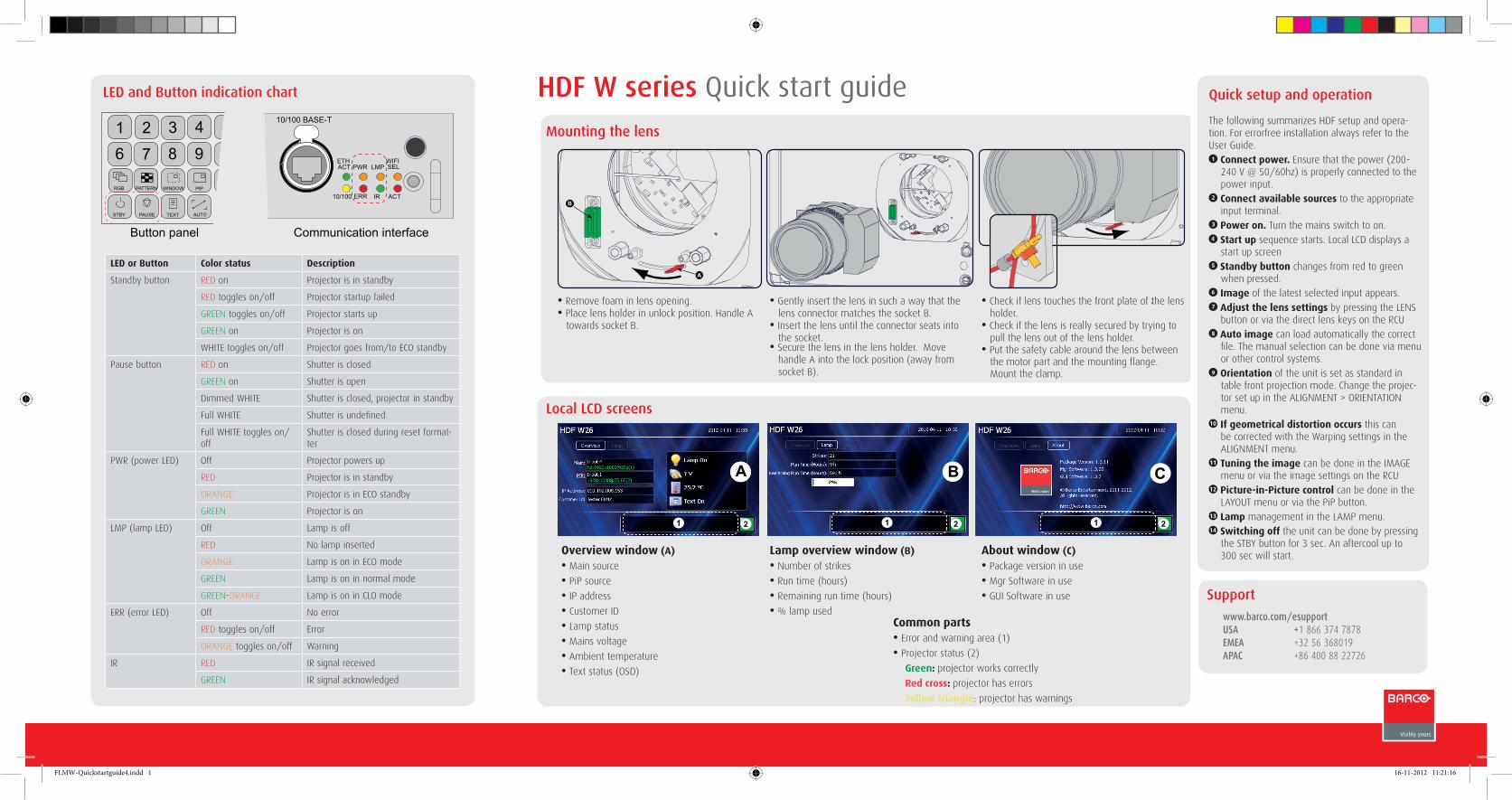
HDF W series Quick start guideMounting the lens
10/100 BASE-T
ETHACT PWR LMP
10/100 ERR IR ACT
WIFISEL
1 2 3 4
6 7 8 9
RGB
STBY PAUSE TEXT
PATTERN WINDOW PIP
AUTO
Button panel Communication interface
LED or Button Color status Description
Standby button RED on Projector is in standby
RED toggles on/off Projector startup failed
GREEN toggles on/off Projector starts up
GREEN on Projector is on
WHITE toggles on/off Projector goes from/to ECO standby
Pause button RED on Shutter is closed
GREEN on Shutter is open
Dimmed WHITE Shutter is closed, projector in standby
Full WHITE Shutter is undefined
Full WHITE toggles on/off
Shutter is closed during reset format-ter
PWR (power LED) Off Projector powers up
RED Projector is in standby
ORANGE Projector is in ECO standby
GREEN Projector is on
LMP (lamp LED) Off Lamp is off
RED No lamp inserted
ORANGE Lamp is on in ECO mode
GREEN Lamp is on in normal mode
GREEN-ORANGE Lamp is on in CLO mode
ERR (error LED) Off No error
RED toggles on/off Error
ORANGE toggles on/off Warning
IR RED IR signal received
GREEN IR signal acknowledged
LED and Button indication chart
Overview window (A)
• Main source
• PiP source
• IP address
• Customer ID
• Lamp status
• Mains voltage
• Ambient temperature
• Text status (OSD)
Lamp overview window (B)
• Number of strikes
• Run time (hours)
• Remaining run time (hours)
• % lamp used
About window (C)
• Package version in use
• Mgr Software in use
• GUI Software in use
Common parts• Error and warning area (1)
• Projector status (2)
Green: projector works correctly
Red cross: projector has errors
Yellow triangle: projector has warnings
• Remove foam in lens opening.• Place lens holder in unlock position. Handle A
towards socket B.
• Gently insert the lens in such a way that the lens connector matches the socket B.
• Insert the lens until the connector seats into the socket.
• Secure the lens in the lens holder. Move handle A into the lock position (away from socket B).
• Check if lens touches the front plate of the lens holder.
• Check if the lens is really secured by trying to pull the lens out of the lens holder.
• Put the safety cable around the lens between the motor part and the mounting flange. Mount the clamp.
A
B
C
1 2
B
1 2
AA
1 2
Local LCD screens
Quick setup and operation
The following summarizes HDF setup and opera-tion. For errorfree installation always refer to the User Guide.
Connect power. Ensure that the power (200-240 V @ 50/60hz) is properly connected to the power input.
Connect available sources to the appropriate input terminal.
Power on. Turn the mains switch to on. Start up sequence starts. Local LCD displays a start up screen
Standby button changes from red to green when pressed.
Image of the latest selected input appears. Adjust the lens settings by pressing the LENS button or via the direct lens keys on the RCU
Auto image can load automatically the correct file. The manual selection can be done via menu or other control systems.
Orientation of the unit is set as standard in table front projection mode. Change the projec-tor set up in the ALIGNMENT > ORIENTATION menu.
If geometrical distortion occurs this can be corrected with the Warping settings in the ALIGNMENT menu.
Tuning the image can be done in the IMAGE menu or via the image settings on the RCU
Picture-in-Picture control can be done in the LAYOUT menu or via the PiP button.
Lamp management in the LAMP menu. Switching off the unit can be done by pressing the STBY button for 3 sec. An aftercool up to 300 sec will start.
1
2
3
4
5
6
7
8
9
10
11
12
13
14
www.barco.com/esupportUSA +1 866 374 7878EMEA +32 56 368019APAC +86 400 88 22726
Support
FLMW-Quickstartguide4.indd 1 16-11-2012 11:21:16
Communication panel
HDF W series Quick start guide
Projector Address
Serial communication
Network
IR control
DMX
Buttons
Menu Position
Local LCD
Change Language
Scheduler
Menu structure
Slot Module Type
Input Locking
Native Resolution
No Signal
EDID
3D*
Image Settings
Aspect Ratio
Timings
Image File Services
Save Custom Settings
Splash image
Main Window
PiP Window
Layout File Services
Same Zoom/Focus
Lamp Power
Identification
Z-axis
Orientation
Lens
Warping
Blanking
Contrast/Intensity
Gamma
Internal patterns
Color Space
ScenergiX
Identification
Diagnostics
Int. Service Patterns
Convergence
Factory Default
USB Memory
Reset Formatter
Refill mode
Save Custom Settings
Sp. HD Camera Mode
Auto Dim overtemp.
Time and Date
INPUT IMAGE LAyOUT LAMPS ALIGNMENT PROjECTOR CONTROL SERvICE
12V /1A
IN DMX OUT REMOTE CTRL
RS232/422 INUSB
10/100 BASE-T
ETHACT PWR LMP
10/100 ERR IR ACT
WIFISEL
1 23
2 3 4 5 6 7 8 1191 1210
WIFI antenna for wireless IP (optional)
12V 1A output
DMX interface input - output
XLR input for wired projector control
RS232 for serial communication
USB backup custom settings
10/100 base-T for external control over IP and Art-Net
Ethernet status lights
Projector Status lights
WIFI status lights
IR receive sensor
GSM antenna input (optional)
Printed on FSC certified paper (www.fsc.org) R5905175 Rev. 01
1
2
3
4
5
6
7
8
9
10
11
12
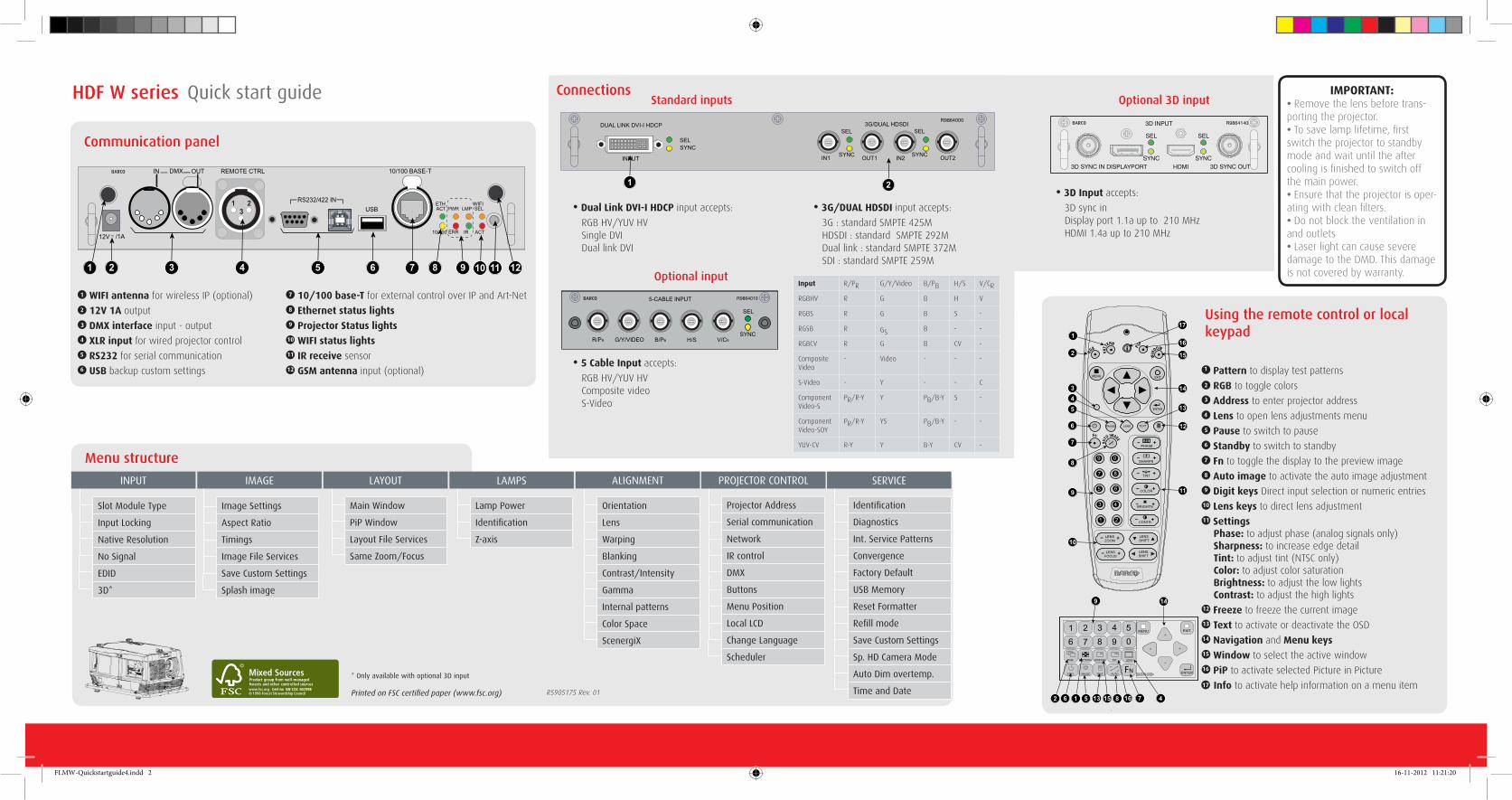
Using the remote control or local keypad
Connections
DUAL LINK DVI-I HDCP
INPUT
SELSYNC
3G/DUAL HDSDI
OUT1IN1 IN2 OUT2
SEL
SYNC
SEL
SYNC
R9864000
1 2
• Dual Link DVI-I HDCP input accepts:
RGB HV/YUV HV Single DVI Dual link DVI
• 3G/DUAL HDSDI input accepts:
3G : standard SMPTE 425M HDSDI : standard SMPTE 292M Dual link : standard SMPTE 372M SDI : standard SMPTE 259M
BARCO
R/PR G/Y/VIDEO B/PB H/S V/CR
5-CABLE INPUT
SEL
SYNC
R9864010
Input R/PR G/Y/Video B/PB H/S V/CR
RGBHV R G B H V
RGBS R G B S -
RGSB R GS B - -
RGBCV R G B CV -
CompositeVideo
- Video - - -
S-Video - Y - - C
Component Video-S
PR/R-Y Y PB/B-Y S -
Component Video-SOY
PR/R-Y YS PB/B-Y - -
YUV-CV R-Y Y B-Y CV -
Optional input
Standard inputsIMPORTANT:
• Remove the lens before trans-porting the projector.• To save lamp lifetime, first switch the projector to standby mode and wait until the after cooling is finished to switch off the main power.• Ensure that the projector is oper-ating with clean filters.• Do not block the ventilation in and outlets • Laser light can cause severe damage to the DMD. This damage is not covered by warranty.
• 5 Cable Input accepts:
RGB HV/YUV HV Composite video S-Video
Pattern to display test patterns
RGB to toggle colors
Address to enter projector address
Lens to open lens adjustments menu
Pause to switch to pause
Standby to switch to standby
Fn to toggle the display to the preview image
Auto image to activate the auto image adjustment
Digit keys Direct input selection or numeric entries
Lens keys to direct lens adjustment
Settings Phase: to adjust phase (analog signals only) Sharpness: to increase edge detail Tint: to adjust tint (NTSC only) Color: to adjust color saturation Brightness: to adjust the low lights Contrast: to adjust the high lights
Freeze to freeze the current image
Text to activate or deactivate the OSD
Navigation and Menu keys
Window to select the active window
PiP to activate selected Picture in Picture
Info to activate help information on a menu item
1
3
4
5
6
2
7
8
9
10
11
12
13
14
15
16
17
MENU EXIT
ENTER
PAUSE TEXT
PHASE
TINT
COLOR
BRIGHTN
CONTR
9 0
7 8
5 6
3 4
1 2
LENS
LENSZOOM
LENSSHIFT
LENSFOCUS
�
SHARPN
LENSSHIFT
RGB
PATT
ERN
PIP
WIN
DOW
Fn
AUTO
IMAGE
1 2 3 4 5
6 7 8 9 0MENU EXIT
ENTER
RGB
STBY PAUSE TEXT
PATTERN WINDOW PIP LENS
AUTOFN
1
2
345
6
7
8
9
10
11
12
13
14
15
16
4716815135162
9 14
17
3D INPUT R9864140
3D SYNC IN DISPLAYPORT HDMI 3D SYNC OUTSYNC
SEL
SYNC
SEL
BARCO
• 3D Input accepts:
3D sync in Display port 1.1a up to 210 MHz HDMI 1.4a up to 210 MHz
Optional 3D input
* Only available with optional 3D input
FLMW-Quickstartguide4.indd 2 16-11-2012 11:21:20