Embed Size (px)
Citation preview

BARC/2016/E/014B
AR
C/2016/E
/014
UNDER SODIUM ULTRASONIC VIEWING FOR FAST BREEDERREACTORS: A REVIEW
byEaglekumar G. Tarpara
Homi Bhabha National Institute (HBNI)and
V.H. PatankarElectronics Division
andN. Vijayan Varier
Ex-Head, TC&QCD,Indira Gandhi Centre for Atomic Research (IGCAR)
BARC/2016/E/014
GOVERNMENT OF INDIAATOMIC ENERGY COMMISSION
BHABHA ATOMIC RESEARCH CENTREMUMBAI, INDIA
2016
BA
RC
/201
6/E
/014
UNDER SODIUM ULTRASONIC VIEWING FOR FAST BREEDERREACTORS: A REVIEW
byEaglekumar G. Tarpara
Homi Bhabha National Institute (HBNI)and
V.H. PatankarElectronics Division
andN. Vijayan Varier
Ex-Head, TC&QCD,Indira Gandhi Centre for Atomic Research (IGCAR)

BIBLIOGRAPHIC DESCRIPTION SHEET FOR TECHNICAL REPORT(as per IS : 9400 - 1980)
01 Security classification : Unclassified
02 Distribution : External
03 Report status : New
04 Series : BARC External
05 Report type : Technical Report
06 Report No. : BARC/2016/E/014
07 Part No. or Volume No. :
08 Contract No. :
10 Title and subtitle : Under sodium ultrasonic viewing for Fast Breeder Reactors: a review
11 Collation : 72 p., 75 figs., 2 ills.
13 Project No. :
20 Personal author(s) : 1. Eaglekumar G. Tarpara2. V.H. Patankar3. N. Vijayan Varier
21 Affiliation of author(s) : 1. Homi Bhabha National Institute, Mumbai
2. Electronics Division, Bhabha Atomic Research Centre, Mumbai
3. TC and QCD, Indira Gandhi Centre for Atomic Research, Kalpakkam
22 Corporate author(s): Bhabha Atomic Research Centre, Mumbai - 400 085
23 Originating unit : Electronics Division, Bhabha Atomic Research Centre,
Mumbai
24 Sponsor(s) Name : Department of Atomic Energy
Type : Government
Contd...
BARC/2016/E/014

BARC/2016/E/014
30 Date of submission : September 2016
31 Publication/Issue date : September 2016
40 Publisher/Distributor : Head, Scientific Information Resource Division, Bhabha Atomic Research Centre, Mumbai
42 Form of distribution : Hard copy
50 Language of text : English
51 Language of summary : English
52 No. of references : 134 refs.
53 Gives data on :
60
70 Keywords/Descriptors : KALPAKKAM PFBR REACTOR; REACTOR SAFETY; FUELASSEMBLIES; ULTRASONIC TESTING; IN-SERVICE INSPECTION; KALPAKKAMLMFBR REACTOR; TRANSDUCERS; SODIUM COOLED REACTORS; IMAGESCANNERS; WAVEGUIDES; PZT
71 INIS Subject Category: S21
99 Supplementary elements :
Abstract: Liquid Metal Fast Breeder Reactors (LMFBR/FBR) are of two types: Loop type and Pool type.Many countries like USA, Japan, UK, Russia, China, France, Lithuania, Belgium, Korea, and India haveworked extensively on these types of FBRs. FBRs are capable of breeding more fissionable fuel than itconsumes like breeding of Plutonium-239 from non-fissionable Uranium-238. In FBR, heat is releasedby fission process and it must be captured and transferred to the electric generator by the liquid metalcoolant (i.e. Sodium). Due to continuous operation and for safety and licensing reasons, periodic inspectionand maintenance is required for reactor fuel assemblies which carry nuclear fuels. For this reason, undersodium ultrasonic imaging technique is adopted as in-service inspection activity for viewing of core ofFBRs. Since liquid sodium is optically opaque, ultrasonic technique is the only method which can beemployed for imaging in liquid sodium. In harsh conditions like high temperature and high radiation,there is a restriction on the development of possible ultrasonic visualization systems and selection of thetransducer materials which can operate in the core region of reactor at around 200 °C during shutdown ofreactor. This report provides a review of works related to ultrasonic imaging in sodium, different materialsused in high temperature transducer assemblies and their different coupling/bonding techniques to achievemaximum transmission efficiency in high temperature sodium environment. The report also provides theoverview of different architectures and imaging methods of transducer array elements which were used inLMFBRs for inspection and visualization of the reactor core sub-assemblies. The report is focused on areview of some possible beamforming techniques which may be used for nuclear applications for hightemperature environment. Published information of the different simulation models are also reviewedwhich can be adopted to simulate the ultrasonic behavior in liquid metal environment, but data areinsufficient to make a conclusion, based on the simulation model. The report is divided into four sectionsexplaining design aspects of high temperature transducer assemblies utilized in liquid sodium, Ultrasonicimaging techniques and instrumentation for viewing of core of FBRs, various possible beamformingmethods for high temperature imaging and simulation modeling for behavior of ultrasonic wave propagationin thermo-hydraulic condition

Abstract
Liquid Metal Fast Breeder Reactors (LMFBR/FBR) are of two types: Loop type and
Pool type. Many countries like USA, Japan, UK, Russia, China, France, Lithuania, Belgium,
Korea, and India have worked extensively on these types of FBRs. FBRs are capable of
breeding more fissionable fuel than it consumes like breeding of Plutonium-239 from non-
fissionable Uranium-238. In FBR, heat is released by fission process and it must be captured
and transferred to the electric generator by the liquid metal coolant (i.e. Sodium). Due to
continuous operation and for safety and licensing reasons, periodic inspection and
maintenance is required for reactor fuel assemblies which carry nuclear fuels. For this reason,
under sodium ultrasonic imaging technique is adopted as in-service inspection activity for
viewing of core of FBRs. Since liquid sodium is optically opaque, ultrasonic technique is the
only method which can be employed for imaging in liquid sodium. In harsh conditions like
high temperature and high radiation, there is a restriction on the development of possible
ultrasonic visualization systems and selection of the transducer materials which can operate
in the core region of reactor at around 200 °C during shutdown of reactor. This report
provides a review of works related to ultrasonic imaging in sodium, different materials used
in high temperature transducer assemblies and their different coupling/bonding techniques to
achieve maximum transmission efficiency in high temperature sodium environment. The
report also provides the overview of different architectures and imaging methods of
transducer array elements which were used in LMFBRs for inspection and visualization of
the reactor core sub-assemblies. The report is focused on a review of some possible
beamforming techniques which may be used for nuclear applications for high temperature
environment. Published information of the different simulation models are also reviewed
which can be adopted to simulate the ultrasonic behavior in liquid metal environment, but
data are insufficient to make a conclusion, based on the simulation model. The report is
divided into four sections explaining design aspects of high temperature transducer
assemblies utilized in liquid sodium, Ultrasonic imaging techniques and instrumentation for
viewing of core of FBRs, various possible beamforming methods for high temperature
imaging and simulation modeling for behavior of ultrasonic wave propagation in thermo-
hydraulic condition.

Contents
List of Figures ................................................................................................................................ 1
List of Tables .................................................................................................................................. 3
Acronyms ........................................................................................................................................ 4
1. Introduction ............................................................................................................................ 6
2. Transducer Assembly and Its Effect In Liquid Sodium Nuclear Environment ..................12
3. Design of Different Ultrasonic Imagers/Viewing Systems ....................................................23
4. Beamforming Methods ..........................................................................................................49
5. Simulation Modeling ..............................................................................................................53
6. Conclusions.............................................................................................................................54
7. Technical References .............................................................................................................56
8. Appendix-I List of Fast Breeder Reactors in world ............................................................64
Appendix-II Categorization of References ............................................................................67

1
List of Figures
Figure 1.1 Temperature effect on Ultrasonic Velocity in Liquid Sodium ............................... 7
Figure 1.2 (a) Basic diagram of a typical LMFR fuel pin and a FSA,
(b) Variation in pin length due to swelling irradiated in FFTF Reactor, USA,
(c) Variation of pin length due to swelling in fuel pins irradiated in BN-600
Reactor, Russia,
(d) Failure of three FSAs of BOR-60 (Russia) Reactor made of AISI 321 SS due
to Swelling and Bending [96] ............................................................................ 10
Figure 2.1 High Temperature Ultrasonic Transducer Assembly ........................................... 12
Figure 2.2 Stainless Steel 316L waveguide with molten eutectic Sn60Pb40 solder. The left
picture shows the normal non-wetting behavior and the right picture shows the
result after application of solder flux to remove the surface oxides [58] ............. 14
Figure 2.3 PNNL single element transducer [61] ................................................................. 17
Figure 2.4 Ultrasonic probe with a BIT/PZT film deposited onto a steel buffer rod [21] ...... 18
Figure 2.5 High temperature 1-3 Piezo-composite transducer [62] ...................................... 18
Figure 3.1 (a) CCPM (core cover plate mechanism) and Under Sodium Ultrasonic Image [9],
(b) Transducer Drive mechanism
(c) under sodium test object,
(d) under sodium image at 300 °C [2] ................................................................ 25
Figure 3.2 (a) Sweep arm scanner head and its individual piezoelectric transducer elements
[61],
(b) HEDL single element ultrasonic transducer with gold coated concave front
face [76],
(c) Core Mock-up at Fast Flux Test Facility (FFTF), Hanford, USA,
(d) The Isometric three-dimensional image “ISO-SCAN” .................................. 26
Figure 3.3 (a), (b) 2-Axes automated sweep arm scanner with water immersible FSAs [45],
(c) Under DM water Depth based imaging of FSAs using sweep arm scanner,
(d) Under DM water Amplitude based imaging of FSAs using sweep arm scanner,
(e) Full circular coverage using sweep arm scanner
(f) NCUIS [50],
(g) Ultrasonic transducer holder assembly of USUSS [49],
(h) Conical Transducer Holder of USUSS Indicating the Mounting Arrangement
for Four SVTs (Spaced 15° Apart),
(i) Conical Transducer Holder of USUSS Indicating the Mounting Arrangement
for Four DVTs (Placed Radially At Distance 57.5mm, 120mm, 160mm, 187mm
on the bottom plate),
(j)USUSS for PFBR, India,
(k) Under Sodium Depth Mode FSA Image acquired using 4-Channel DVS at 180
°C. Four DVTs are located at 50mm above core plenum with Angular Step
Resolution: 1° and Coverage: 0° to 360°,
(l) Under Sodium Depth Mode FSA Image acquired using 4-Channel DVS with
Angular Step Resolution: 0.5° and Coverage: 0° to 360° .................................... 31
Figure 3.4 (a) PFR core top before the reactor was filled with sodium,
(b)-(c) Under sodium Image,
(d) Rigid Under Sodium Viewer (RUSV), PFR [4, 7],

2
(e)-(f) LSAS [29],
(g) Full size LSAS [29],
(h)Under water set up for ultrasonic imaging,
(i) Under water images of FSAs by LSAS [29],
(j) Schematic of deployment sequence of LSAS while scanning operation in
reactor core [4 ,7] .............................................................................................. 34
Figure 3.5 (a) Schematic of lance of SAS,
(b) Testing of lance with sweep arm ................................................................... 34
Figure 3.6 (a) 12-element ultrasonic linear array [76],
(b) High temperature linear array assembly [31],
(c) Near-field acoustic response of 12-element array[76],
(d) brush-type linear ultrasonic waveguide transducer (UWT) array [31] ........... 35
Figure 3.7 (a) Ultrasonic Orthogonal Array system “IMARSOD” [42],
(b) “VISUS” [29] .............................................................................................. 37
Figure 3.8 (a) “Multihead” fitted circularly parabolic transducers [8],
(b) Under sodium image of object at 230 °C ...................................................... 37
Figure 3.9 (a) (b) 2 -D matrix of 36×36 transducer elements [5],
(c) Schematic of Under Sodium Target, Under sodium images at
(d) Distance: 700 mm and (e) Distance: 1000 mm .............................................. 38
Figure 3.10(a) Piezo elements bonded with faceplate with wire,
(b) C-scan image of pin tops at 50 mm standoff distance [124] .......................... 39
Figure 3.11(a) Setup of sodium wetting experiment [61],
(b) Sodium facility for ultrasonic testing in France [15],
(c) Thick protector transducer [57, 20]............................................................... 40
Figure 3.12(a) Under-Sodium Viewing Facility, ANL, USA,
(b) Under-sodium image: 1-Acoustic signal reflected from target, 2-TOF image,
3-Intensity image, 4- Corresponding scanning area on the target,
(c) A prototype ultrasonic waveguide with bundle-rod and spiraled-sheet hybrid
design [79] ........................................................................................................ 43
Figure 3.13(a) Bundle type waveguide [74],
(b) Schematic of the cylindrical rod waveguide [60],
(c) Clad buffer rod [36] ..................................................................................... 43
Figure 3.14(a) Comb shape based transducer element for waveguide [39],
(b) Plate type waveguide, UK [39],
(c) 10 m plate waveguide with liquid wedge [78],
(d) Ultrasonic mode conversion, leaky wave generation and propagation using
plate type waveguide [81, 78],
(e) Schematic design of dual waveguide sensor [54]
(f) Waveguide based beam profile measurement experiment setup [81],
(g) Under Water C-Scan Images, (h) Under Sodium C-Scan images .................. 46
Figure 3.15 DLC coated transducer [57] .............................................................................. 47
Figure 3.16 Fuel Identification Mockups ............................................................................. 48

3
List of Tables
TABLE 2.1 Different Faceplate Materials of High temperature Ultrasonic Transducers ...... 14
TABLE 2.2 Piezoelectric Elements and Properties .............................................................. 20

4
Acronyms
ADC Analog to Digital Convertors
AERE Atomic Energy Research Establishment (UK)
AISI American Iron and Steel Institute (USA)
AlN Aluminium Nitride
AlTiO3 Aluminum Titanium Oxide
ANL Argonne National Laboratory (USA)
BARC Bhabha Atomic Research Centre (India)
BI4Ti3O2(BIT) Bismuth Titanate
CCPM Core Cover Plate Mechanism
CDFR Commercial Demonstration Fast Reactor (UK)
CEFR China Experimental Fast Reactor (China)
CVD Chemical Vapor Deposition
DLC Diamond Like Carbon
DOE Department of Energy
DVT Downward Viewing Transducer
FBR Fast Breeder Reactor
FBTR Fast Breeder Test Reactor (India)
FFTF Fast Flux Test Facility (USA)
FIFO First In First Out
FSA Fuel Sub-Assembly
GaPO4 Gallium Orthophosphate
GFR gas cooled fast reactor
HEDL Hanford Engineering Development Laboratory (USA)
IGCAR Indira Gandhi Centre for Atomic Research (India)
LBE Lead-Bismuth Eutectic
LFR Lead cooled Fast Reactor
LiNbO3 Lithium Niobate
LMFBR Liquid Metal Fast Breeder Reactors

5
LMFR Liquid Metal Fast Reactors
LSAS Linked Sweep-Arm Scanner
MI Mineral Insulated
MSFR Molten Salt Fast Reactor
MYRRHA Multi-purpose hYbrid Research Reactor for High-tech Applications
NCUIS Non-Contact Ultrasonic Inspection System
NDT Non-Destructive Testing
PA Phased Array
PbNb2O6 Lead Metaniobate
PFBR Prototype Fast Breeder Reactor (India)
PFR Prototype Fast Reactor (UK)
PNNL Pacific Northwest National Laboratory (USA)
PZT Lead Zirconate Titanate
RUSV Rigid Under Sodium Viewer
SAFT Synthetic Aperture Focusing Technique
SCK•CEN Dutch: Studiecentrum voor Kernenergie, French: Centre d'Étude de
l'énergie Nucléaire
SFR Sodium-cooled Fast Reactor
SPA Sampling Phased Array
SVT Side Viewing Transducer
TUCSS Transducteur à Ultrasons pour CND Sous Sodium (Ultrasonic transducer
for NDT under sodium)
TUSHT Traducteur UltraSonore Haute Temperature
UDV Ultrasound Doppler Velocimetry
UKAEA UK Atomic Energy Authority (UK)
USUSS Under Sodium Ultrasonic Scanner
UVS Ultrasonic Viewing System
YCOB Yttrium Calcium Oxyborate

6
1. INTRODUCTION
number of countries like USA, Japan, UK, France, Russia, China, Lithuania, Belgium,
Korea, and India have built and operated fast (also accelerator-driven) metal-cooled pool
type nuclear reactors and they have used liquid metal as the core coolant which is used as a
heat transfer fluid from the reactor core to the steam generator. So the reactor core and in-
vessel structures of a liquid metal fast reactor are submerged in a liquid metal pool. A variety
of liquid metal coolants like mercury, Molten salt, sodium, lead-bismuth eutectic (LBE) have
been used worldwide and most of them except some countries like Lithuania and Belgium
which use Pb/Bi alloy as coolant, are using liquid sodium as a coolant in Fast reactors as it
has a high thermal conductivity, it does not moderate or slowdown the fast neutrons and it
causes less corrosion of the reactor components without forming impurities. The world‟s first
fast-neutron reactor was Clementine, a 25 KWt, mercury-cooled experimental reactor built at
Omega Site at Los Alamos, USA and it was permanently shut down in 1952 [130]. At
present, four FBRs are in operation: the China Experimental Fast Reactor (CEFR) in China,
the Fast Breeder Test Reactor (FBTR) in India, and the BOR-60 and BN-600 reactors in the
Russian Federation. Two FBRs, Joyo and Monju in Japan, are in temporary shutdown due to
accidents. Two FBRs are in commissioning stage: the 500 MWe Prototype Fast Breeder
Reactor (PFBR) in India and the 880 MWe BN-800 reactor in the Russian Federation [130,
131, 132]. The detailed description of various current and future FBRs are indicated in
Appendix-I.
In the sodium-cooled fast reactor (SFR), the in-service inspection is necessary to
examine the integrity of the safety-related structures of SFR. During maintenance and fuel
handling, the PFBR (India) presently under commissioning stage, will be in shut down
condition, coolant temperature will be at 180 °C, the neutron flux will be 120 n/cm2/s,
gamma levels decrease to 1.2×10³ Sv/h (Sieverts per hour), the sodium flow velocity will be
0.91 m/s and the sodium pressure will be up to 500 mbar. At reactor shutdown, sodium
temperature will be lowered to 150-180 °C and therefore, the in-service inspection (ISI)
needs to be performed at this temperature. Since liquid sodium is optically opaque and
electrically conductive, a conventional visual inspection cannot be used for observing the
internal structures under a harsh sodium environment and electromagnetic methods are also
significantly limited due to the nature of metal and salt ions in a molten state [79]. So the
ultrasonic imaging is the only technique which can be effectively used for viewing the
submerged components in the core of reactor, core supports, and refueling hardware [1, 2, 3,
5, 6, 10, 11, 14, 17]. The other applications of the ultrasonic system are: identifying in-vessel
core sub-assemblies, determining the orientation of hexagonal core components and other
remotely placed equipment, ascertaining the structural integrity of materials and structures
during reactor operation, determining the elevation and lateral profiles of fuel duct assemblies
and searching of missing components in the core inside the reactor [2].
As temperature increases, the physical properties of sodium changes like density
decreases, acoustic velocity decreases, thermal conductivity decreases and electric resistivity
increases [10]. So the ultrasonic imaging system including transmitters, receivers, and
transducer housing material must operate continuously with high voltages and high gains in
very harsh conditions including high temperature and gamma radiation. For Lead Zirconate
Titanate (PZT-5A) material of the transducer crystal, the temperature dependent piezoelectric
coefficient d33 and coupling factor k33 are stable up to 200 °C and 150 °C respectively. But
k33 exhibits slight temperature dependence above 200 °C. The temperature sensitivity for
both piezoelectric coefficients d31 and electromechanical coupling factor k33 are very small in
the range of 120 to 200 °C [66]. In liquid metal, the main problems are the wetting and
A

7
corrosiveness of ultrasonic transducer casing. The wetting is poor in static liquid sodium
since sodium absorbs oxygen from the inert atmosphere available inside the reactor vessel.
Thus, it is difficult for transducers to function while testing and imaging in static liquid
sodium since ultrasound cannot be transmitted through an unwet interface between the liquid
sodium and front face (diaphragm) of the transducer, and all signals are reflected by an
essentially equivalent gas layer between the transducer face and the liquid sodium [3]. There
are also other problems like selection of suitable piezoelectric material for operation at high
temperature and in highly radioactive environment, optimization of transducer construction,
acoustic coupling in a wide temperature range of a piezoelectric material with the faceplate
and backing element, the long-term stable acoustic contact between front face of transducer
element and liquid metal and selection of electrical co-axial cables suitable for high
temperature and high radiation environment [18]. When the nuclear reactor is shutdown, the
neutron flux is negligible, so only the effect of gamma radiation is important. In under-
sodium condition, gamma radiation damages the immersed ultrasonic transducer assembly
like it causes an effect on the active piezoelectric element, backing material, faceplate layer
(or focusing lens), external housing and co-axial cable/electrical leads [14]. The temperature
(T) effect on ultrasonic velocity (V) in liquid sodium is given by equation [71].
𝑉 = 2723− 0.531 × 𝑇 °C + 273.15 𝑚/𝑠
The plot related to above equation is shown in Figure 1.1 and it indicates that
ultrasonic velocity decreases with increasing temperature.
Figure 1.1 Temperature effect on Ultrasonic Velocity in Liquid Sodium
The methodology of ultrasonic inspection is a well known technique [90, 91, 92].
Generally, there are two types of ultrasonic sensors which are used in SFR for imaging and
non-destructive testing purposes: (1) Immersible sensor and (2) Waveguide based sensor. In
immersion type sensors, the ultrasonic transducer assembly is immersed in liquid sodium and
placed nearer to the object under inspection and produces high-resolution images of FSAs
0 100 200 300 400 5002300
2350
2400
2450
2500
2550
2600
Sodium Temperature (°C)
Aco
ust
ic V
elo
city
of
So
diu
m (
m/s
)

8
and structures. On the other hand, waveguide based sensor keeps the ultrasonic transducer in
cold region i.e. outside the reactor vessel. The ultrasonic wave travels via long waveguide
which is partially immersed in liquid sodium and permits the use of piezo ceramic material
with lower Curie temperature and also minimizes the thermal shock and radiation damages to
the transducers.
1.1. Core-Mapping of FBR
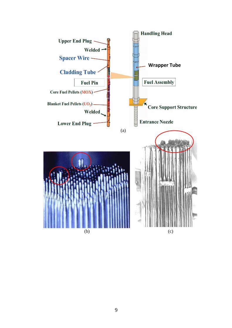
In a fast breeder reactor, the heat is generated by nuclear fission in the core where
core consists of the large number of Fuel Sub-Assemblies (FSAs). Each FSA consists of a
hexagonal wrapper tube which contains bundles of clad tubes or fuel pins, filled with fuel
pellets as shown in Figure 1.2 (a). In PFBR (India), there are 181 FSAs which are arranged in
a triangular array. Each FSA consists of 217 fuel pins [48]. During normal operation of the
reactor, the temperature of liquid sodium is more than 550 °C and the neutron flux levels are
about two orders of magnitude higher as compared to equivalent thermal reactors.
Deformation of various components of the SAs can occur due to void swelling, thermal creep
and irradiation creep. Differential swelling can occur because of gradients in flux and
difference in temperature at various locations in the reactor core due to the inter-assembly
heat transfer. Wrapper deformation is expected to be limited; otherwise, the interaction
between wrappers will lead to obstruction in fuel handling. At the center of the core,
subassemblies are expected to remain straight with an elongation and an increase of distance
across surfaces of adjacent SAs. But at the periphery, subassemblies can tend to bow
outwards called as “flowering” due to differential void swelling on the opposite faces of the
wrapper tube as a consequence of neutron flux gradient. There would be differential thermal
expansion and differential swelling across the width of the SA. Hence, the SA will tend to
bow to accommodate the differential expansion. Higher the neutron flux gradient, bowing
will be more. The extent of bowing is dependent on its location in the core as the flux
gradually reduces towards the core periphery. Due to high temperature and flow of liquid
sodium, there is also a possibility of growth of FSAs [49, 94, 95, 96]. The variation in pins
seen in Figure 1.2 (b)-(c) is the result of the combined action of swelling and irradiation
creep. Once swelling exceeds 15–20%, failure can occur under the liquid sodium by swelling
and irradiation creep, leading to mechanical interference with neighboring FSAs and support
structure during attempts to extract the ducts from the core [96]. An example is shown in
Figure 1.2 (d).
9
(a)
(b) (c)
Wrapper Tube

10
(d)
Figure 1.2 (a) Basic diagram of a typical LMFR fuel pin and a FSA, (b) Variation in pin
length due to swelling irradiated in FFTF Reactor, USA, (c) Variation of pin length due
to swelling in fuel pins irradiated in BN-600 Reactor, Russia, (d) Failure of three FSAs
of BOR-60 (Russia) Reactor made of AISI 321 SS during attempts to extract the ducts
from the core due to Swelling and Bending [96]
In FBR core, small motions in the fuel region can lead to changes in the core
reactivity. Since positive reactivity is added when the core assemblies are displaced radially
inward, the phenomenon of bowing has importance for safety and control point of view. But
bowing is important because fuel handling to lift out the FSAs will become more difficult if
there is an excessive bowing. Excessive bowing also makes insertion of an outer ring FSA
(not fully burnt) with more bows into a location in inner ring. Measurement of bow also gives
idea of extent of damage of wrapper of FSA. So determination of bow is useful although it is
not mandatory. So the Core-mapping is required to locate, identify and quantify the growth
and bowing of FSAs. For inspection and viewing, the system based on ultrasonic imaging
will be deployed during the shutdown campaign of the reactor when the temperature of liquid
sodium is around 180 °C in PFBR (India). The system software should have a provision to
compare current data with the reference/base-line data of the FBR core to quantify the extent
of growth and bowing of FSAs in the core.
1.2. Scope of Literature Review
The review is subdivided into five sections as below:
1) Discussion on various components of ultrasonic transducer assembly and analysis of
degradation and failure mechanism of transducer at high temperature and radiation
environment in liquid sodium, as explained in Section No. 2.
2) Description to identify suitable material for different components of transducer assembly
which can sustain high temperature and high gamma dose is provided in Section No. 2.
3) Categorization and review of various design methodologies of ultrasonic systems which
have been used in immersible mode and non- immersible (waveguide) manner to view the

11
reactor core during in-service inspection and maintenance purposes, are explained in
Section No. 3.
4) Classification of various ultrasonic beamforming methods for immersible transducer array
elements and discussion on advantages and drawbacks of each method, are described in
Section No. 4.
5) Review of the published literature regarding the simulation modeling of ultrasonic
propagation in high temperature gradient and turbulent liquid sodium flow environment;
have been elaborated in Section No. 5.

12
2. TRANSDUCER ASSEMBLY AND ITS EFFECT IN LIQUID SODIUM
NUCLEAR ENVIRONMENT
Many countries have published literature about various fabrication methods with
different transducer assembly structures and the concepts are evolved over a long time. The
most general structure of high-temperature ultrasonic transducer assembly is given in Figure
2.1 [2, 10, 76]. The extensive reviews for high-temperature ultrasonic transducer materials
are available [10, 13]. Also, the detailed review related to radiation resistant adhesives for
transducer materials has been provided by Sinclair et al. [14].
Figure 2.1 High Temperature Ultrasonic Transducer Assembly
2.1. Faceplate/ Protector Diaphragm and Faceplate Coatings
The faceplate of the transducer assembly is a vital component as it directly makes
contact with the liquid sodium. Its function is to transfer the acoustic wave generated by
piezo element material to the liquid metal and vice-versa. The face plate has either flat or
curved surface. In some applications, the curved faceplate is used to focus the ultrasonic
beam at a fixed depth to achieve required better lateral resolution. In the case of a flat surface,
the central lobe of the near field beam determines the lateral resolution and it is lower than
the curved type lateral beam resolution. Although focused transducer provides better lateral
resolution at focal distance, Swaminathan et al. [44] have mentioned and used unfocused
transducers for under sodium imaging. The reasons are that there is a deployment problem in
the reactor, especially for the Downward Viewing Transducers (DVTs) which are mounted in
the scanning head with their lens looking downward. Special arrangements are required to
prevent or remove the entrapment of argon gas bubbles in the concave portion of the lens, i.e.
transducer‟s front-face where inert gas argon environment is maintained above the sodium
level inside the reactor vessel of FBR.
The importance is the selection of suitable faceplate material which can sustain in
harsh environment and the selected material should be wettable by liquid sodium at 200 °C
temperature. Wetting is the ability of a liquid to maintain contact with a solid surface,
resulting from intermolecular interaction when the two mediums are brought together. In a

13
non-wetting system with a rough solid surface, if the real microscopic contact surface is
considerably smaller than the apparent macroscopic surface area that means higher surface
contact angle, then such roughness hampers the transmission of ultrasonic waves.
Alternatively, the same rough surface in a wetting liquid finds its roughness crevices filled by
the liquid due to the capillary effect and the entire surface will be in close contact with the
liquid, effecting in proper ultrasonic transmission [58]. Thus the surface roughness of the
front face of diaphragm plays a major role for effective sodium wetting. Air gaps due to
excess surface roughness can cause problems in wetting and in ultrasonic energy transmission
and reception.
The wetting of stainless steel is dependent on the relationship of time and
temperature. Above 800 °F wetting of stainless steel with liquid sodium is rapid and below
800 °F wetting takes a long time to complete. The wetting time also depends on the amount
of oxygen dissolved in sodium and surface condition of faceplate layer [3, 1]. The acoustic
coupling material deteriorates due to the formation of the oxide layer on the face plate of the
transducer [58]. The surface preparation and long lasting experimental methods can be used
for testing of Wettability. The other techniques used to improve wetting are cleaning the
transducer faceplate by thermal etching and gold depositing process at high temperature.
When the transducer is placed in sodium, gold dissolves away and front face will wet by the
hot liquid sodium [1, 3]. Many other methods are also used and tested to overcome this
problem: Electroplating of stainless steel by Ni, Sn or Bi, Deposition of various surface
metallic coatings of Pt, Al, IrO, Mo, Ta and Diamond like carbon (DLC). Soldering and
Sn/Bi coating were used successfully at lower temperatures (< 200 °C) but their dissolution
in a liquid Pb/Bi was slow. Out of these methods, only DLC coating and polished optical
methods have provided proper long-term wetting performance in LBE [20, 18]. But DLC
coating has not been so far tested in liquid sodium environment. In the fully wetted situation,
the transducer normally provides comparable pulse-echo amplitude in sodium as in water but
only causes the decrement of few dB signal value in liquid sodium. So the water can be used
to investigate the transmission/reception behavior of ultrasonic waves instead of liquid
sodium and LBE. The simple theoretical proof for this has been provided by Dierckx et al.
[58]. There was only 6 dB decrement over a period of 125 hours liquid sodium experiment at
200 °C [44]. Ultrasonic cleaner also cannot be used to clean the faceplate of the under
sodium transducers.
The sodium wetting depends on surface roughness as mentioned earlier. Recently
nickel coating layer was micro-polished to obtain average surface roughness less than 0.02
µm on prototype waveguide outer surface for improvement of sodium wetting [81]. Wetting
of the waveguide tip in the Pb/Bi alloy was obtained by cleaning the waveguide tip carefully
with acetone and covering it by a 20 μm Teflon film. Just before immersion, the oxides were
wiped off the alloy surface and after the immersion; the film got peeled off due to hot LBE
[20]. The wetting of metal surface can be found in the field of brazing and soldering.
Generally, flux is applied to improve wetting during brazing. For initial wetting and to
remove the oxides from the surface of the transducer lens in Pb/Bi eutectic alloy, the lens i.e.
front face of the transducer was soldered by the SN60PB40 solder as shown in Figure 2.2.
However, the long-term wetting with liquid metal could not be achieved by this solder [58].

14
Figure 2.2 Stainless Steel 316L waveguide with molten eutectic Sn60Pb40 solder. The left
picture shows the normal non-wetting behavior and the right picture shows the result
after application of solder flux to remove the surface oxides [58]
TABLE 2.1
DIFFERENT FACEPLATE MATERIALS OF HIGH TEMPERATURE ULTRASONIC TRANSDUCERS
Coating Materials Tested
in Remarks Country
Diamond like carbon
(DLC)
PB/bi Tested in liquid Pb/Bi up to 450 °C [18, 20] Belgium
Gold coating Sodium Tested in Liquid sodium at 500 °C, Wetting is
temperature depended and takes < 5 seconds [1]
Sustain at temperature up to 1000 °C using Gold
sputter layer [32]
immediately dissolved so re-wetting is required
[61]
USA
Stainless Steel Sodium Wets very slowly in liquid sodium
sacrificial gold coating layer is required
Polished Nickel and
Nickel alloy
Sodium May wet in sodium [2]
Tested in liquid sodium at 180 °C, immediate
wetting [9, 76]
Polished nickel lens tested in liquid sodium [44,
72] and gave immediate wetting
Japan, India,
USA
Alloy 52 (50% nickel),
Alloy 200 (100% nickel)
Sodium Tested in liquid sodium at 260 °C, good sodium
wetting [61]
Coefficient of thermal expansion of alloy 52
matches with bismuth titanate [10]
USA
Invar alloy Sodium Coefficient of thermal expansion matches with
piezoelectric ceramics [5]
Japan
Titanium Coefficient of thermal expansion matches with
bismuth titanate [10]
No testing in liquid sodium
15
The different faceplate coating materials and their characteristics are shown in Table
2.1. The immersible transducer assembly with faceplate coating material of nickel (Alloy 52,
Alloy 200, polished), gold coating and Stainless Steel were tested in liquid sodium. Some
designs used polished Stainless Steel and a gold coating to achieve quick sodium wetting.
Since the gold coating instantaneously dissolves in liquid sodium, regularly re-coating is
required. So it is preferable to have a transducer faceplate material that wets without the need
of re-coating. Previously published data states that gold coating immediately dissolves in
sodium [1] and Nickel alloy [9, 7], Alloy 52 [61] and Alloy 200 [61] provided proper
sodium wetting. Nickel was also used for the faceplate of the TUCSS transducer in France
and Griffin et al. [76] have used nickel alloy foil for 12 linear array transducers with 2-MHz
lead metaniobate piezoelectric material.
2.2. Piezoelectric Element
The Piezoelectric material used in high temperature environment must have Curie
temperature higher than the maximum operating temperature of liquid metal in reactor,
during ultrasonic testing. It causes a restriction of selecting the possible piezoelectric
materials which can sustain in high temperature environment. Matching of transducer-
diaphragm thermal expansion coefficient is very important to prevent thermal shock damage.
The bonding material should have sufficient ductility to minimize stresses at the transducer-
diaphragm interface [10]. The selection of piezoelement material is mainly based on three
important parameters: Curie temperature (Tc), Acoustic coupling factor (d33) and damping
coefficient or mechanical Q factor. The Curie temperature must be higher than the reactor in-
service or shutdown operation temperature. The acoustic coupling factor should be higher
and mechanical Q factor should be lower as its lower value provides better self-damping
ability for proper ultrasonic operation. Various Piezoelectric materials have been investigated
and tested at high temperature and high radiation under liquid metal environment.
Most authors have stated that Lead Zirconate Titanate (PZT) [10, 7], Bismuth
Titanate [13, 18], Lead Metaniobate [8, 13, 72] and Lithium Niobate [2, 7, 8, 10, 26, 32, 41]
are suitable materials for high temperature and radiation environment. PZT and related
materials have been tested in liquid sodium environment at 180 °C [9], at 220 °C [5] and at
280 °C temperature [26]. Its lower Curie temperature restricts it‟s use at a very high
temperature >300 °C. Since it has high piezoelectric sensitivities (d33) at high temperatures,
the various parameters of PZT are very sensitive to temperature fluctuations specifically for
value of piezomodules, resonance frequency, etc. which leads to strong amplitude and phase
fluctuations in the received signals [6]. Bismuth titanate is best suitable material at elevated
temperature as it has high Curie temperature and it has only 4% decrease in the transfer
coefficient at 22.7 MGy (22.7 ×10⁶ Sv) gamma radiation dose [18] and also it does not show
any noticeable changes of pulse responses and transfer coefficients during irradiation and
high temperature testing [20]. A high temperature experimental comparison between three
materials: Yttrium Calcium Oxyborate single crystal YCa4O(BO3)3 (YCOB), Lithium
Niobate LiNbO3, and Aluminium Nitride AlN has been made by Parks et al. [64]. It is
concluded that at atmospheric oxygen partial pressures, 48 h of exposure to 1000 °C, there
was no any significant effect on the efficiency of ultrasonic transduction of YCa4O(BO3)3,
LiNbO3, and AlN. It was also concluded that particularly YCOB is more stable than LiNbO3
and YCOB is capable of efficient ultrasonic transduction to about 1000°C temperature [67].
The detailed reviews of suitable piezoelement materials have been provided in Table 2.2.
The piezoelectric materials must be acoustically coupled with the faceplate/protector

16
and the damping body material if it is used. Broadly, there are three types of coupling
concepts: (1) Dry Coupling, (2) Liquid Coupling and (3) Solid Coupling. They are described
as below:
1) Dry Coupling
Since there is no coupling material between layers of piezoelement and faceplate, an
external force is required to press the piezoelement to the faceplate. In dry coupling, a very
small air gap (<0.01 µm) is to be achieved to reduce the acoustic loss and pressure up to 300
MPa is required to reduce the air gap between two layers. So surface roughness should also
be <0.01µm. Dry coupling with λ/2 and λ membrane was not quite successful because
membrane can bend when the external pressure is applied. During dry coupling with a gold
foil insertion, it was observed that there was no change in ultrasonic signal shape and
amplitude at 20 °C to 450 °C temperature for 100 hour operation and it has been used
successfully in the case of waveguides [20]. Dry coupling with gold foil between transducer
and waveguide was also tested in liquid sodium at 340 °C [79]. A silver pressure bonding
technique was used to bond the PZT as well as Lithium Niobate transducer elements and both
were tested in liquid sodium at temperature of 320 °C and 550 °C for 315 days effectively
[26].
2) Liquid Coupling
Liquid coupling can be divided into two types: high temperature liquid couplant such
as silicon oil and glass solders which are solid at room temperature and melt at high
temperature. Silicon oil couplant gradually evaporates with increases in temperature so it was
successfully used up to 250 °C. Liquid couplant can flow out from the interfaces such as
faceplate-piezoelement or piezoelement-damping body layer due to vibration of
piezoelement, so it can lose its chemical stability and also it is required to withstand against
severe gamma radiation [20]. Literature suggested several couplants like Couplant E up to
260 °C and 540 °C and Sono 100 film up to 593 °C [13]. Glass solder like NaPoLi can be
used at high temperature up to 500 °C but their use is doubtful in radioactive environment
[20]. But glass solder started react chemically with transducer components as the temperature
increased and thus limited to the application up to 500°C [134].
3) Solid Coupling
This type of piezoelement is usually soldered to the faceplate and/or damping body
using the soft solders. A solder should be elastic in nature to compensate the vibration of
piezoelement and different temperature expansions of the piezoelement, backing material and
protector/faceplate. At high temperature, only a limited number of solders are suitable like
gold based solder. The necessary condition for solder is that the melting temperature of solder
must be lower than the recommended maximum temperature or Curie temperature of
piezoelement and higher than the recommended maximum operating temperature in liquid
metal environment. Alumina based ceramic Cotronics 989 was used at 400 °C for lithium
niobate piezoelement but it was not radiation proof [20]. Nowadays, it has been found that
the diffusion bonding technique is very effective. It provides reliable joints which are suitable
even when the joined materials have different thermal coefficient of expansion and also
suitable for thermal shock environment. The gold to gold bonding is suitable for diffusion
bonding for bismuth titanate piezoelement up to 400 °C [20]. In Pacific Northwest National
Laboratory (PNNL), they have used high-temperature glues and epoxy adhesives to bond the
piezo-element to the nickel alloy faceplate. But due to temperature-induced failures and
gamma radiation damages in the organic adhesives, they have eliminated epoxy adhesives.
Since low temperature silver solder is a chemically stable, it was used on an inner surface of
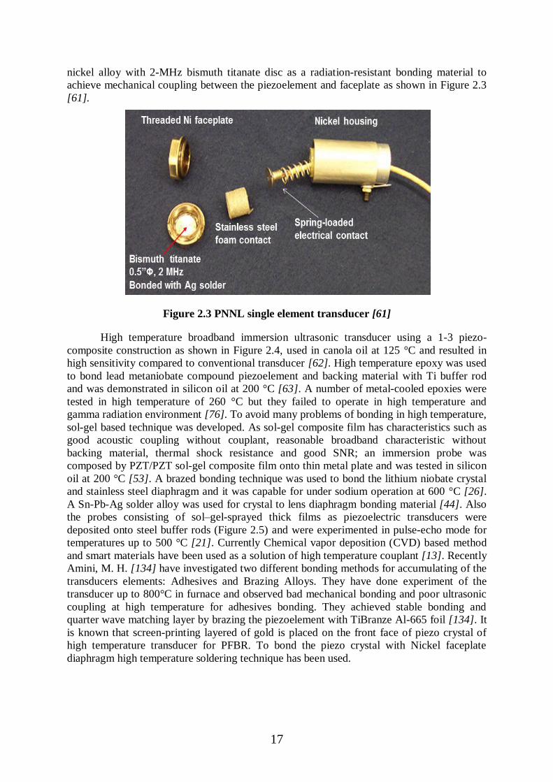
17
nickel alloy with 2-MHz bismuth titanate disc as a radiation-resistant bonding material to
achieve mechanical coupling between the piezoelement and faceplate as shown in Figure 2.3
[61].
Figure 2.3 PNNL single element transducer [61]
High temperature broadband immersion ultrasonic transducer using a 1-3 piezo-
composite construction as shown in Figure 2.4, used in canola oil at 125 °C and resulted in
high sensitivity compared to conventional transducer [62]. High temperature epoxy was used
to bond lead metaniobate compound piezoelement and backing material with Ti buffer rod
and was demonstrated in silicon oil at 200 °C [63]. A number of metal-cooled epoxies were
tested in high temperature of 260 °C but they failed to operate in high temperature and
gamma radiation environment [76]. To avoid many problems of bonding in high temperature,
sol-gel based technique was developed. As sol-gel composite film has characteristics such as
good acoustic coupling without couplant, reasonable broadband characteristic without
backing material, thermal shock resistance and good SNR; an immersion probe was
composed by PZT/PZT sol-gel composite film onto thin metal plate and was tested in silicon
oil at 200 °C [53]. A brazed bonding technique was used to bond the lithium niobate crystal
and stainless steel diaphragm and it was capable for under sodium operation at 600 °C [26].
A Sn-Pb-Ag solder alloy was used for crystal to lens diaphragm bonding material [44]. Also
the probes consisting of sol–gel-sprayed thick films as piezoelectric transducers were
deposited onto steel buffer rods (Figure 2.5) and were experimented in pulse-echo mode for
temperatures up to 500 °C [21]. Currently Chemical vapor deposition (CVD) based method
and smart materials have been used as a solution of high temperature couplant [13]. Recently
Amini, M. H. [134] have investigated two different bonding methods for accumulating of the
transducers elements: Adhesives and Brazing Alloys. They have done experiment of the
transducer up to 800°C in furnace and observed bad mechanical bonding and poor ultrasonic
coupling at high temperature for adhesives bonding. They achieved stable bonding and
quarter wave matching layer by brazing the piezoelement with TiBranze Al-665 foil [134]. It
is known that screen-printing layered of gold is placed on the front face of piezo crystal of
high temperature transducer for PFBR. To bond the piezo crystal with Nickel faceplate
diaphragm high temperature soldering technique has been used.

18
Figure 2.4 Ultrasonic probe with a BIT/PZT film deposited onto a steel buffer rod [21]
Figure 2.5 High temperature 1-3 Piezo-composite transducer [62]
2.3. Backing Material
The backing material must have high damping and strong adhesion characteristics
which makes the output ultrasonic signal shorter in time domain and wider in frequency
domain but at the cost of reduction in signal energy. It is generally acoustically lossy ceramic
type material and also has the same acoustic impedance matching with the piezoelectric
element to minimize the acoustic energy reflected back from the transducer element. The
failure of bonding of backing layer with piezoelectric element does not lead to complete
transducer failure but leads to an unacceptable distortion of the signal like ringing and it
causes the reduction of bandwidth and degradation of timing resolution of ultrasonic echoes
[14]. The PbNb2O6 piezoelement material was bonded to the backing solid polyamide as it
has acceptable ultrasonic damping through a high temperature epoxy, while the rod with a
thin layer of silicone oil was used as couplant in between [63]. Even if transducer assembly is
fractured or damaged due to high temperature thermal shock, the rear electrode must maintain
electrical contact with the entire back face of the transducer assembly specially a combination
of transducer element and backing layer. Smith et al. [12] have used a woven disc of gold-
coated wire, copper-beryllium mesh and Stainless Steel foam to maintain electrical contacts.
This flexible electrode material was spring-loaded against the back side of the transducer
assembly. AlTiO3 ceramic has been used as a damping material because of its good
performance above 200 °C [5]. It is very difficult to get a radiation resistant material which
can withstand gamma radiation in liquid sodium. Recently a novel porous ceramic material
based backing material for ultrasonic transducers was designed and manufactured by Amini,
M. H. [133]. They used 3 mol % yttria-stabilized zirconia ceramic for backing material with
lithium niobate crystal. They achieved acoustic impedance of 24MRayls and minimum
attenuation of 1dB/mm over the entire transducer bandwidth of 1.5 to 4.3MHz by performing
acoustic measurements at temperatures up to 800°C.
19
2.4. Assembly Housing and Signal Cable
The suitable materials for the transducer housing are the Stainless Steel as well as
alloy of nickel, with the reference to the available literatures for the development of under
sodium ultrasonic imaging system. Some literature stated that Stainless Steel takes few hours
to wet in liquid sodium during operation [10]. Some of the used housing materials in high
temperature and radiation environment are: Stainless Steel (used in liquid sodium up to 300
°C [2] and 260 °C [8]), Nickel (used in liquid sodium up to 200 °C [44] and 250°C [72]),
Stainless Steel AISI 316 (used in liquid Pb/Bi alloy up to 160 °C - 460 °C [20]), AISI 304L
used in TUSHT transducer [43], SUS 204 used in liquid sodium up to 200 °C [5] and
Inconel-600 [13]. If the gamma field has minor low-energy photons, Stainless Steel housing
is suitable for shielding the interiors of the transducer [14].
The cable connected to the high temperature transducer of FBR should have low
capacitance (pF/foot) to minimize loading to the pulser and attenuation of the excitation
pulse. It is important to get perfect impedance matching between the cable impedance and the
impedance of the ultrasonic pulser/receiver for the transducers itself in high temperature and
radiation environment. Electrical circuitry such as impedance matching hardware cannot be
placed in the transducer housing as electronics components have low gamma radiation
resistance [14]. Mostly Co-axial type signal cables have been used for under-sodium viewing
in a high-radiation environment in nuclear reactor [2, 10]. The most used co-axial cable is
two-conductor “Mineral Insulated cable” (MI cable). The detailed construction and
advantages are available in online literature [93]. Some of the literatures have mentioned the
different co-axial cable materials and their dimensions which can sustain high temperature
and radiation environment such as 1-mm diameter and 15-m long mineral cable was used in
the liquid Pb/Bi coolant at the temperature range 160 °C–460 °C [20] for MYRRHA reactor
in Belgium, high-temperature mineral cable [57], a coaxial cable made of SS [8] with
magnesium oxide insulators was used as an electrical cable applicable up to 900 °C [21] in
Canada, a high-frequency cable with a diameter 1 mm and length 15 m was used to transmit
the signals for the underwater gamma irradiation test with dose rate in the range of 10–30
kGy/h [20] in Belgium, a MI Cable with diameter 1.6- mm was used in liquid sodium at 350
°C [2] and a MI cable of 6 m was used up to 200 °C in liquid sodium [44, 72].
Unexpected transducer failure can impose major operational difficulties due to
gamma radiation and it is very difficult and time consuming process to replace the damaged
transducers with the new transducers placed in core region. An elaborated review has been
published by the Sinclair et al. [14] about the determination of cumulative expected gamma
dose lifetime for “conventional” ultrasonic transducers in gamma radiation and neutron
environment. Radiation damage in conventional transducer normally leads first to
degradation of their performance such as reduction in sensitivity and narrowing bandwidth,
but not leading to instant transducer failure. They have suggested the possible piezoelement
material: PZT (for <200 °C), Lead Metaniobate (for 200 °C to 325 °C), Lithium Niobate,
Aluminum Nitride, or composites but they have poor piezoelectric efficiency and higher cost;
housing material: Stainless Steel and Aluminum; cable material: MgO2 based mineral cable
and SiO2 based cable. Kazys et al. [20] have reported efficiency of LiNbO3, GaPO4,
Bi4Ti3O12, and AlN piezomaterials for various gamma dose up to 33 MGy and concluded that
bismuth titanate sensor experienced only a 4% decrease in the transfer coefficient, while the
efficiency of the gallium orthophosphate sensor decreased by 13%. The detailed review has
been provided in Table 2.2.
Normally in-service inspection has been carried out in reactor shutdown period, when
the neutron flux is expected to be very low and damages of the transducer assembly would be

20
only due to gamma radiations. If inspection has been carried out during on-line operational
inspection in reactor core, then only the effect of neutron must be considered. So there is a
limited interest to study the effect of neutron damage of the transducer in nuclear power
application. Recently Sinclair et al. [14] have concluded that due to lack of the related
publications and measurement data it was not possible to get relative conclusions regarding
the lifetime of transducer damages caused by neutron radiation.
TABLE 2.2
PIEZOELECTRIC ELEMENTS AND PROPERTIES [10, 13, 14, 18, 20, 28, 57, 64, 67, 69, 70, 77,
80]
No. Material
Curie
temperature Tc
(°C)
Remarks
1 Lead Zirconate
Titanate PZT 5A (and
variants)
250-360 Tested in liquid sodium at 180 °C, India [9]; 220
°C, Japan [5]; 285 °C, USA [10]
PZT (SP-6) with Tc = 380 °C tested in liquid
sodium at 200 °C [44]
70% coupling efficiency
Lower curie temperature
Reliable operation up to gamma radiation doses of
1.5 MGy [22]
Permanent damage threshold of ~ 400 MGy of
gamma radiation [27]
Reduced gain, capacitance and electromechanical
coupling co-efficient for 1019-1020 n/cm2 of
neutron dose [27]
Only less than 1% variation on resonance
frequency against the neuron irradiation of
1.6×10²¹ n/cm2 for 150 days [22]
2 Bismuth Titanate
BI4Ti3O2 (and
variants)
600 (K15), 820
(K12)
Tested in Pb/Bi alloy at 450 °C, Belgium [18]
Tested in liquid sodium at 260 °C, USA [61]
ultrasonic attenuation in liquid sodium is low
Sensitivity lower than PZT
High piezoelectric stability
Low dielectric constant and losses, properties are
stable up to high temperature
Kezite K12 have Tc = 820 °C, kt =0.07 °C, High
Q factor (200) and Low coupling efficiency
(12%)
Kezite K15 have Tc = 820 °C, kt =0.07 °C, Good
Q factor 100 and only 10% bandwidth
Only slight decrease of the piezoelectric transfer
coefficient at 10–30 kGy/h [18]
Only 4% reduction of piezoelectric coefficient at
22.7 MGy [18]
21
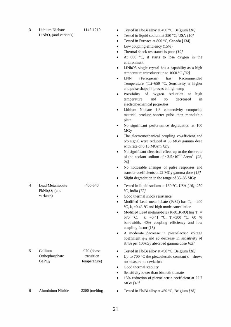
3 Lithium Niobate
LiNbO3 (and variants)
1142-1210 Tested in Pb/Bi alloy at 450 °C, Belgium [18]
Tested in liquid sodium at 250 °C, USA [10]
Tested in Furnace at 800 °C, Canada [134]
Low coupling efficiency (15%)
Thermal shock resistance is poor [19]
At 600 °C, it starts to lose oxygen in the
environment
LiNbO3 single crystal has a capability as a high
temperature transducer up to 1000 °C [32]
LNN (Ferroperm) has Recommended
Temperature (To)=650 °C, Sensitivity is higher
and pulse shape improves at high temp
Possibility of oxygen reduction at high
temperature and so decreased in
electromechanical properties
Lithium Niobate 1-3 connectivity composite
material produce shorter pulse than monolithic
plate
No significant performance degradation at 100
MGy
The electromechanical coupling co-efficient and
o/p signal were reduced at 35 MGy gamma dose
with rate of 0.15 MGy/h [27]
No significant electrical effect up to the dose rate
of the coolant sodium of ~3.5×10⁻¹² A/cm2 [23,
24]
No noticeable changes of pulse responses and
transfer coefficients at 22 MGy gamma dose [18]
Slight degradation in the range of 35–88 MGy
4 Lead Metaniobate
PbNb2O6 (and
variants)
400-540 Tested in liquid sodium at 180 °C, USA [10]; 250
°C, India [72]
Good thermal shock resistance
Modified Lead metaniobate (Pz32) has Tc = 400
°C, kt =0.43 °C and high mode cancellation
Modified Lead metaniobate (K-81,K-83) has Tc =
570 °C, kt =0.41 °C, To=300 °C, 60 %
bandwidth, 40% coupling efficiency and low
coupling factor (15)
A moderate decrease in piezoelectric voltage
coefficient g33 and so decrease in sensitivity of
8.4% per 100kGy absorbed gamma dose [65]
5 Gallium
Orthophosphate
GaPO4
970 (phase
transition
temperature)
Tested in Pb/Bi alloy at 450 °C, Belgium [18]
Up to 700 °C the piezoelectric constant d11 shows
no measurable deviation
Good thermal stability
Sensitivity lower than bismuth titanate
13% reduction of piezoelectric coefficient at 22.7
MGy [18]
6 Aluminium Nitride 2200 (melting Tested in Pb/Bi alloy at 450 °C, Belgium [18]

22
AIN temperature) Low dielectric permittivity (8.6) and high velocity
(10700 m/s)
Good thermal shock resistance up to 1200 °K
[19]
Good gamma radiation robustness at 18.7 MGy
[18]
Sensitivity lower than bismuth titanate
No significant performance degradation (d33) at a
fast and thermal neutron dose of 1.85×10¹⁸ n/cm2
and 5.8×10¹⁸ n/cm2 respectively and a gamma
dose of 26.8 MGy [33, 128]
7 Quartz High Q factor(10000)
Low coupling efficiency (11%)
8 Barium Titanate 120 Drop in polarization above 1 MGy for single
crystals
Decreased coercive field and increase of
spontaneous polarization at 1MGy gamma dose
and 1011-1014 n/cm2 neutron dose [27]
9 YCOB 1400-1500 More stable than lithium niobate
Tested at 950 °C for 24h and 100 °C for 48h
Capable for ultrasonic transmission up to 1000 °C
No phase transformation up to 1500 °C [30]

23
3. DESIGN OF DIFFERENT ULTRASONIC IMAGERS/VIEWING
SYSTEMS
The ideal design of reactor core should have sufficient availability of space for
placing the transducer assembly to inspect/view entire core region during in-service
inspection and maintenance period of reactor. But in general, it has been observed that
adequate provisions are not made for such activities during the design process of reactor [10].
So the main constraints of the design of different imaging system is the limited space and
availability of access in the reactor vessel for motion of ultrasonic viewing system (UVS) and
it hampers the inspection/viewing campaign in reactor vessel. And these constraints reduce
the resolution of the captured ultrasonic images. The design of ultrasonic imagers also depend
on the deployment of the transducer assembly due to limited viewing ports in reactor for
insertion of the whole assembly such as Prototype Fast Reactor (PFR), UK which had a
cylinder of 10 m length and 250 mm diameter for insertion of the inspection assembly [7]
and also they had deployed sequence of link manipulator in the PFR core [29]. The ultrasonic
viewer was inserted through the opening hole called “experimental canal” of diameter 104
mm in the rotating plug of Fast Breeder Test Reactor (FBTR), India [9].
3.1. Sweep-Arm Scanner with Single Element Transducer
Due to deployment constraints and limited availability of insertion space in the reactor
vessel, the Sweep-Arm Scanning (SAS) system is one of the important solutions. SAS system
is used to maneuver the transducer assembly in both circular and linear direction in order to
scan core region of the reactor. SAS have additional arm length to deploy the ultrasonic
transducers over the core for scanning the core from centre of the observation port. Due to the
restricted size of observation port as mention above, a mechanism required to be provided in
the SAS will be such that arm length/radius can be increased inside the reactor vessel during
scanning operation and can be decreased while inserting into the reactor vessel or taking out
from the reactor vessel through observation port. SAS enhances the region of inspection for
reactor core and reduces scanning time.
India had developed and deployed the prototype ultrasonic viewer to scan the space
below the core cover plate mechanism (CCPM) of the FBTR to image the CCPM and
demonstrated its horizontal (side) viewing capability in liquid sodium of the FBTR core [9].
The viewer was consisting of a 10 m long and 33 mm diameter stainless (Spinner) tube inside
90 mm diameter guide tube. Ultrasonic transducer has been placed at the bottom of the tube
facing sideways. The transducer assembly and spinner tubes are controlled by the drive panel.
The linear or elevation increment distance of this sweep-arm viewer was 1-mm with
clockwise or counter clockwise angular rotation in 0.9° steps over an angle of 72° [9]. The
under sodium image is shown in Figure 3.1 (a). The Ultrasonic imaging of the immersible
reactor components namely Control and Safety Rod Drive Mechanism (CSRDM)/ Diverse
Safety Rod Drive Mechanism (DSRDM) and Control and Safety Rods (CSR) was carried out
in water by scanning the above core plenum by deploying the Under Sodium Ultrasonic
Scanner (USUSS). Also the protrusion of neutron absorber rods and their drive mechanisms
can be detected and located using ultrasonic imaging technique. However, the extreme
conical portion of absorber rod drive mechanisms cannot be imaged, but the positions can be
cross checked using position sensors before starting the fuel handing operation [46].
Toshiba Corporation, Japan and Power Reactor and Nuclear Fuel Development
Corporation (PNC), Japan has jointly developed a vertical under sodium imaging system
using high temperature transducer and transducer drive mechanism. They used vertical type
scanner and a transducer was attached at the bottom of the scanner end. For utilizing the

24
limited installation space and avoiding excessive stress on the signal wire a spiral trace
scanning was selected as shown in Figure 3.1 (b). Drive mechanism was tested in air at room
temperature and in sodium at 350 °C. Whole system was tested in water as well as in liquid
sodium at 300 °C. They have taken the under sodium image of a special target as shown in
Figure 3.1 (c) and it‟s under sodium image is shown in Figure 3.1 (d). The required time to
take the image was less than 3 minute [2].
(a)
(b)

25
(c) (d)
Figure 3.1(a) CCPM (core cover plate mechanism) and Under Sodium Ultrasonic Image
[9], (b) Transducer Drive mechanism (c) under sodium test object, (d) under sodium
image at 300 °C [2]
3.2. Sweep-Arm Scanner with Multiple Ultrasonic Transducers
3.2.1. FFTF, Hanford site, USA
USA has designed and developed the ultrasonic azimuthally-scanner with linear array
of eight focused ultrasonic transducers (Figure 3.2 (a)) for the Department of Energy‟s (DOE)
Fast Flux Test Facility (FFTF), a prototype liquid metal cooled fast reactor at Hanford site,
USA [3, 61]. They have carried out eighteen in-sodium transducer experiments in 1972. Nine
long-term tests were performed in reactor-grade sodium for approximately 300 hours, with
the sodium temperature varying from 187°C (460°F) to 217°C (490°F). At the conclusion of
these experiments, the transducers of PZT material (Figure 3.2 (b)) had retained
approximately 50% of the pulse-echo sensitivity. Two other tests were performed for 160
hours and 650 hours at sodium temperatures ranging from 187°C to 217°C. The isometric
three-dimensional image “ISO-SCAN” (Figure 3.2 (c)) has been constructed on a memory-
type cathode ray tube (CRT) by the individually eight transducers placed radially in a single
row through angular rotation and time of flight data [3].
(a) (b)

26
(c) (d)
Figure 3.2 (a) Sweep arm scanner head and its individual piezoelectric transducer
elements [61], (b) HEDL single element ultrasonic transducer with gold coated concave
front face [76], (c) Core Mock-up at Fast Flux Test Facility (FFTF), Hanford, USA, (d)
The Isometric three-dimensional image “ISO-SCAN”
3.2.2. PFBR, DAE, India
Bhabha Atomic Research Centre (BARC), India and Indira Gandhi Centre for Atomic
Research (IGCAR), India have jointly collaborated in a project to design a sweep-arm based
scanner and ultrasonic imaging system for core-mapping of liquid sodium submerged Fuel
sub Assemblies (FSAs) of PFBR. This system will be used for detection of growth and
bowing of in-core FSAs due to high temperature, gamma and neutron radiation and high
sodium flow rate. Recently, BARC and IGCAR have jointly designed, developed and
deployed the prototype automated two axes Z-θ Sweep-Arm Scanner and ultrasonic imaging
system for under water imaging of 90 mm tall FSA top heads for a core diameter of 1170
mm. The sweep-arm has a length of 300mm with four PZT-5A based ultrasonic transducers,
mounted radially with 90 mm pitch such that sweep-arm can cover the distance of 585 mm in
radial direction as depicted in Figure 3.3 (a)-(b). This scanner provides circular resolution of
1° and spatial (linear) resolution of 1mm. They have tested sweep-arm scanner by acquiring
depth and amplitude based C-scan images of FSAs in Demineralised (DM) water as shown in
Fig 3.3 (c)-(e) [45].
Previously, the same team had designed and developed automated Under Sodium
UltraSonic Scanner (USUSS) (Figure 3.3 (g)-(i)) to detect 5 mm growth in FSA top-heads
and 25 mm protrusion at a distance of 1 meter using FSA top-heads of PFBR, immersed in
liquid sodium at 180 °C. During shutdown of PFBR and before every Fuel Handling
campaign, USUSS will be used for detection of growth and protrusion of FSAs. 5 MHz
Downward Viewing Transducers (DVTs) and 1 MHz Side Viewing Transducers (SVTs)

27
were used respectively along with 8-channel ultrasonic imaging system. The under sodium
images of USUSS are shown in Figure 3.3 (k)-(l) at 180°C. After every imaging operation,
the mechanical scanner along with the transducers is stored in the argon filled storage pit. So
before every campaign of USUSS, it is necessary to check the functionality of the sodium
immersible, contaminated, ultrasonic transducers. For that purpose, BARC has designed and
developed a Non-Contact Ultrasonic Inspection System (NCUIS) as shown in Figure 3.3 (f),
based on air-coupled T-R mode of ultrasonics [48, 49, 50]. In NCUIS, ultrasound travels
through Argon from one transducer to the SVT or DVT transducer to confirm that they are
functionally proper. This is carried out before start of each campaign of USUSS.
(a) (b)
(c)

28
(d)
(e)

29
(f) (g)
(h)
(i) (j)
SVT1 SVT2 SVT3 SVT4
DVT1 DVT2
DVT3
DVT4
DVT1 DVT2
DVT3
DVT4

30
(k)
(l)

31
Figure 3.3 (a), (b) 2-Axes automated sweep arm scanner with water immersed FSAs
[45], (c) Under-water Depth based C-Scan imaging of FSAs using sweep arm scanner,
(d) Under-water Amplitude based C-scan imaging of FSAs using sweep arm scanner, (e)
C-scan image covering large area using sweep arm scanner (f) NCUIS [50], (g)
Ultrasonic transducer holder assembly of USUSS [49], (h) Conical Transducer Holder
of USUSS Indicating the Mounting Arrangement for Four SVTs (Spaced 15° Apart), (i)
Conical Transducer Holder of USUSS Indicating the Mounting Arrangement for Four
DVTs (Placed Radially At Distance 57.5mm, 120mm, 160mm, 187mm on the bottom
plate), (j)USUSS for PFBR, India, (k) Under Sodium Depth Mode C-Scan Image
acquired using 4-Channel imaging at 180 °C. Four DVTs were located at 50mm above
core plenum and with Angular Step Resolution of 1° and Coverage of 360°, (l) Under
Sodium Depth Mode C-Scan Image acquired using 4-Channel imaging with Angular
Step Resolution of 0.5° and Coverage of 360°
3.2.3. PFR and CDFR, UK
In the past, UK Atomic Energy Authority (UKAEA) and National Nuclear
Corporation, UK had worked jointly for project of the in-service inspection in reactor core.
They used eight downward facing and four side mounted transducers in ultrasonic viewer
assembly with frequency of 5MHz as shown in Figure 3.4 (d). The viewer can rotate the
assembly around its own axis such that transducer can be swept over an annular region of the
reactor core. The height precision of viewer is 0.25 mm [4, 7, 29]. Figure 3.4 (a)-(d) shows
the FSAs and under sodium images. Both lateral displacement and vertical growth of the fuel
subassemblies were measured within the accuracy of 0.5 mm and 0.25 mm respectively. It
took approximately 3 hours to scan one complete annular region of FSAs.
They had also designed and developed the “Linked Sweep-Arm Scanner” (LSAS)
system for deployment in Commercial Demonstration Fast Reactor (CDFR) as shown in
Figure 3.4 (e)-(f).The LSAS had a vertical tubular mast which was passed through a
penetration in the reactor rotating shield from the pile cap to place just above the core. An
arm was pivoted to the lower end of the mast so that it can be lowered from the vertical
insertion position within the envelope of the mast to a horizontal position. The arm was
lowered and raised by means of a sliding tube controlled by an actuator at the top of the mast.
The pivots joining the links of the chain were arranged at the bottom of the links and
ultrasonic transducers were mounted in selected links such that ultrasound beam can project
in downward direction towards the core top. The complete details of the deployment
sequences of LSAS are provided in Figure 3.4 (j). Full size prototype components of the
LSAS bottom are shown in Figure 3.4 (g). Preliminary tests were performed using a single
transducer mounted with its axis vertically downwards in one link as shown in Figure 3.4 (h).
Figure 3.4 (i) shows a scan of short tubular cylinders FSAs tops which were a reduced
version 0.625:1 scale and they achieved 0.5 mm precision of the links feed motion [29].
32
(a) (b)
(c) (d)

33
(e)
(f) (g)
(h) (i)

34
(j)
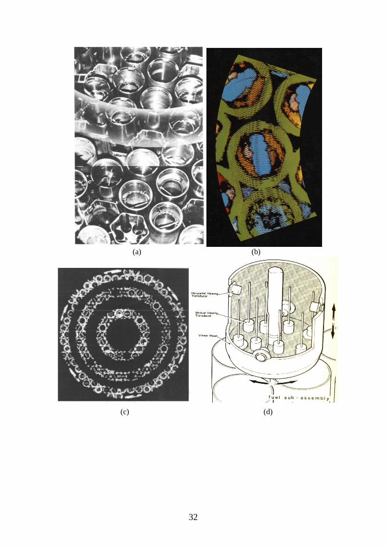
Figure 3.4 (a) PFR core top before the reactor was filled with sodium, (b)-(c) Under
sodium Image, (d) Rigid Under Sodium Viewer (RUSV), PFR [4, 7], (e)-(f) LSAS [29],
(g) Full size LSAS [29], (h)Under water set up for ultrasonic imaging, (i) Under water
images of FSAs by LSAS [29], (j) Schematic of deployment sequence of LSAS while
scanning operation in reactor core [4 ,7]
3.2.4. SNR-300, Germany
The sweep arm scanner for SNR -300 consists of ~2.5 m long offset arm and multi
head transducer as shown in Figure 3.6 (a)-(b). They used two servomotor drives for rotation
of the arm and radial movement of multi head. Initial testing of scanner was carried out in
Freon. Afterward, they have done experiment in liquid sodium at 230o. The under sodium
images are shown in Figure 3.6 (b). Time taken for scanning the 1 square meter area of the
core was around 3 to 6 hours [8].
3.2.4.1.
(a) (b)
Figure 3.5 (a) Schematic of lance of SAS, (b) Testing of lance with sweep arm

35
3.3. Conventional Linear Array and Orthogonal Linear Array
The linear array based ultrasonic imaging technique is widely used for medical and
industrial applications. PNNL, USA has designed and developed the linear array system for
under sodium imaging in sodium cooled fast reactor at temperature 260 °C for in-service
inspection and maintenance activities of the reactor. The prototype transducer array assembly
was designed with 12/24 transducers, as shown in Figure 3.6 (a) of 2MHz rectangular Lead
meta-niobate piezoelectric (K-81) elements spaced at λ/2 distance (wavelength in sodium). A
nickel alloy foil was used for faceplate material which served as sodium wetting surface. The
transducer array assembly is shown in Figure 3.6 (b). The C-scan image measured 5 mm
distance from the transducer faceplate is given as Figure 3.6 (c). Scan angle of the focused
ultrasonic beam was ±30 degrees and spatial resolution was ≤ 1mm. Its high temperature
under sodium imaging data is not available. They have also developed a brush-type linear
ultrasonic waveguide transducer (UWT) array [31, 76] for under sodium application as
shown in Figure 3.6 (d).
(a) (b)
(c) (d)
Figure 3.6 (a) 12-element ultrasonic linear array [76], (b) High temperature linear array
assembly [31], (c) Near-field acoustic response of 12-element array[76], (d) brush-type
linear ultrasonic waveguide transducer (UWT) array [31]

36
France has developed an ultrasonic orthogonal array system “IMARSOD” for in-
service inspection and repair technique developments (ISI&R) in French Liquid Metal Fast
Reactors (LMFR). Earlier they developed the “VISUS” non-imaging ultrasonic system to
detect and locate possible obstacles during operation in Phenix and Super Phenix reactor as
depicted in Figure 3.7 (b) [29]. The IMARSOD system has two perpendicular 128 elements
linear arrays, one working as transmitter and the other working as a receiver as shown in
Figure 3.7 (a). These arrays were designed such that their focal zones approximately
represent horizontal and vertical line, respectively. The electronic focusing by time delay
laws intervening between elements was used to move focal point in three dimensions. France
has validated this system in water [40, 42].
(a)

37
(b)
Figure 3.7 (a) Ultrasonic Orthogonal Array system “IMARSOD” [42], (b) “VISUS” [29]
3.4. Circular Array based Parabolic Transducers
This new type of ultrasonic imaging system has been developed by [8, 51] Germany.
They have used eight receiving transducers with focal lenses called “multihead” fitted
circularly around the central focused transmitter-receiver sensor as shown in Figure 3.8 (a).
These were arranged such that longitudinal axis of all transducers are in the same spatial
point. The viewer used arm based handling devices for imaging in reactor core. The lateral
and axial resolution capability of viewer is 0.5 mm and 1.0 mm respectively. The under
sodium image is shown in Figure 3.8 (b). Time required for one square meter imaging area
was 3 to 6 hours with transducer frequency 4 MHz in liquid sodium with 250 °C.
(a) (b)
Figure 3.8 (a) “Multihead” fitted circularly parabolic transducers [8], (b) Under sodium
image of object at 230 °C
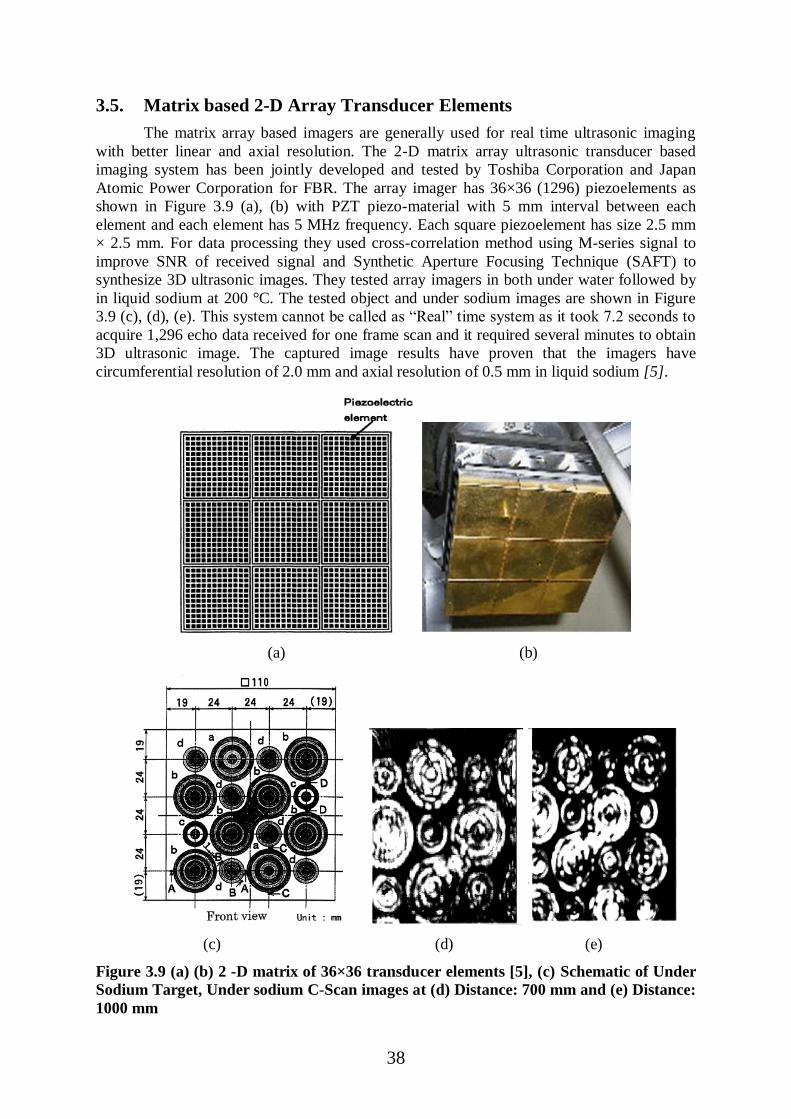
38
3.5. Matrix based 2-D Array Transducer Elements
The matrix array based imagers are generally used for real time ultrasonic imaging
with better linear and axial resolution. The 2-D matrix array ultrasonic transducer based
imaging system has been jointly developed and tested by Toshiba Corporation and Japan
Atomic Power Corporation for FBR. The array imager has 36×36 (1296) piezoelements as
shown in Figure 3.9 (a), (b) with PZT piezo-material with 5 mm interval between each
element and each element has 5 MHz frequency. Each square piezoelement has size 2.5 mm
× 2.5 mm. For data processing they used cross-correlation method using M-series signal to
improve SNR of received signal and Synthetic Aperture Focusing Technique (SAFT) to
synthesize 3D ultrasonic images. They tested array imagers in both under water followed by
in liquid sodium at 200 °C. The tested object and under sodium images are shown in Figure
3.9 (c), (d), (e). This system cannot be called as “Real” time system as it took 7.2 seconds to
acquire 1,296 echo data received for one frame scan and it required several minutes to obtain
3D ultrasonic image. The captured image results have proven that the imagers have
circumferential resolution of 2.0 mm and axial resolution of 0.5 mm in liquid sodium [5].
(a) (b)
(c) (d) (e)
Figure 3.9 (a) (b) 2 -D matrix of 36×36 transducer elements [5], (c) Schematic of Under
Sodium Target, Under sodium C-Scan images at (d) Distance: 700 mm and (e) Distance:
1000 mm

39
PNNL, USA has designed and fabricated 2D matrix (20× 3) phased array transducers
with 60 elements. To reduce the probe noise, the array design has Transmit-receive
longitudinal (TRL) configuration where the transmitter and receiver are physically isolated.
The elements have size 1.8 mm×1.8 mm with 0.2 mm gap between each element and
transmitter and receiver array are separated by 10 mm as shown in Figure 3.10 (a). The 2
MHz PZT crystal was attached to the Nickel faceplate using solder process. They have tested
array into water and resulted that 59 out of 60 elements were working properly. C-scan image
of the underwater target was captured but it exhibited poor SNR due to cabling issue as
shown in Figure 3.10 (b) [124].
(a)
(b)
Figure 3.10 (a) Piezo elements bonded with faceplate with wire, (b) C-scan image of pin
tops at 50 mm standoff distance [124]
3.6. Under Sodium Viewing/Testing Facility for transducer material
Characterization
This type of facility is not used for imaging and inspection of the core of a nuclear
reactor. It was utilized for R&D purpose to investigate and measure the different properties of
ultrasonic transducer with various materials at different high temperature and radiation
environment. Hanford Engineering Development Laboratory (HEDL), USA has developed an
ultrasonic wetting experiment facility for testing the performance of single element
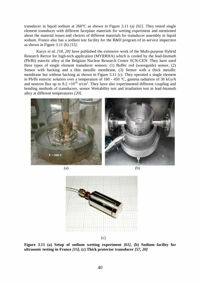
40
transducer in liquid sodium at 260°C as shown in Figure 3.11 (a) [61]. They tested single
element transducer with different faceplate materials for wetting experiment and mentioned
about the material issues and choices of different materials for transducer assembly in liquid
sodium. France also has a sodium test facility for the R&D program of in-service inspection
as shown in Figure 3.11 (b) [15].
Kazys et al. [18, 20] have published the extensive work of the Multi-purpose Hybrid
Research Rector for high-tech application (MYRRHA) which is cooled by the lead-bismuth
(Pb/Bi) eutectic alloy at the Belgium Nuclear Research Centre SCN-CEN. They have used
three types of single element transducer sensors: (1) Buffer rod (waveguide) sensor, (2)
Sensor with backing and a thin metallic membrane, (3) Sensor with a thick metallic
membrane but without backing as shown in Figure 3.11 (c). They operated a single element
in Pb/Bi eutectic solution over a temperature of 160 - 450 °C, gamma radiation of 30 kGy/h
and neutron flux up to 8.2 ×10¹⁸
n/cm2. They have also experimented different coupling and
bonding methods of transducers, sensor Wettability test and irradiation test in lead-bismuth
alloy at different temperatures [20].
(a) (b)
(c)
Figure 3.11 (a) Setup of sodium wetting experiment [61], (b) Sodium facility for
ultrasonic testing in France [15], (c) Thick protector transducer [57, 20]

41
3.7. Waveguide based imaging
Ultrasonic Waveguide is a mechanical element along which elastic waves propagate
from a transducer-waveguide junction to the sensing location in the medium being monitored.
The main purpose of a waveguide is to isolate the transmitting/receiving transducer from the
high temperature and radiation environment. The piezoelectric crystal of transducer perform
in a better manner when it is located in a cool environment i.e. much below the curie
temperature of its piezoelectric crystal and there are no more constraints for the selection of
piezoelectric material of the transducer. This arrangement enhances the transducer
performance and increases sensitivity and the cost of a PZT transducer is lower than that of a
high-temperature transducer. Due to limited space availability in reactor core, the waveguide
design is required to be modified according to available space. Since A-scan echo signal
results of the waveguide show multiple reflections of acoustic waves inside the waveguide,
the measurement on the acquired results becomes complex. These multiple reflections are
called “spurious echoes” in pulse echo mode imaging and they are produced due to
dispersion, mode conversion, wave reverberation, diffraction within waveguide of finite
diameter and scattering echoes from random grains or voids in the rod materials. These
spurious echoes cause poor SNR and reduce detection sensitivity [10, 21, 79]. Literatures
have proposed different waveguide designs for enhancement of SNR and reduction of effect
of the spurious signals. These spurious echo signals can be eliminated significantly by
subtracting background signals, measured without the sample, from the signals measured
with the sample by digital signal processing techniques because the amplitude and time delay
of these spurious signals are fixed at a constant temperature [21]. The extensive review has
been made by Denslow et al. [10] according to the different types of waveguides such as
smooth rod, threaded rod, focused clad rod, bundle wire technology (BWT) waveguide and
spiraled sheet waveguide which were used in the nuclear reactor for under sodium imaging.
Nuclear Engineering Division, Argonne National Laboratory (ANL), USA has
compared the four designs of waveguides having same length such as smooth rod waveguide,
threaded rod waveguide, bundle wire rod waveguide and spiral-sheet rod waveguide. The
smooth rod was a solid Stainless Steel rod; the threaded rod was a solid Stainless Steel rod
with threads (12 threads per 25.4 mm); the bundle rod consists of an array of thin Stainless
Steel rods tightly packed inside a stainless steel tube; and the spiral-sheet rod is fabricated by
wrapping a shim stock around a tube. The test was performed in water with 5 MHz
longitudinal transducer (0.5 in. diameter) and 200V transmit pulse voltage. Ideal waveguide
should have high energy transmitted into the liquid medium, low attenuation (dB/m) and low
time span of mode conversion signal. The tested results concluded that smooth rod can
transfer more energy into liquid sodium medium and has less attenuation compared to all but
it has a largest time of span for mode conversion which would decrease the SNR and
detection capability. Spiral sheet waveguide has smallest time of span and has enhanced SNR
[35,80]. Based on test results, ANL Scientists have designed and developed 12 inch
“Prototype Waveguide” which was a combination of both bundled-rod and spiraled-sheet
designs and used about 35% thin rods and 65% shim stock with gold plated focus lens (focal
length 1” in air) as shown in Figure 3.12 (c). They tested prototype waveguide in liquid
sodium at 377 °C (650 °F) and the estimated attenuation was 1.6 dB/m. Results show that it
had a better detection capability with minimal background noise due to effectively reduction
of spurious echoes and mode conversions. C-scan images of a target were acquired using
time-of-flight as well as amplitude variations of the reflected echoes and it showed that this
prototype can detect defects with 1 mm in width and 0.5 mm in depth in molten sodium as
depicted in Figure 3.12 (b) [34, 35, 79]. Linear array waveguide based design can be used for
side viewing and downward viewing applications [80]. The clad rod buffer waveguide as

42
shown in Figure 3.13 (c) was tested in water and molten Zinc environment at 600 °C and has
obtained C-scan images of steel specimen immersed in molten Zinc. Since the leakage of
ultrasonic energy got reduced from the periphery of rod into medium, the clad rod buffer
provided better SNR than non-clad rod [36]. The clad steel buffer rod with 10 MHz
frequency was tested in molten Aluminum with temperature >780 °C and SNR of more than
33 dB was obtained for the desired echo signal received from the surface at the focal length
in molten Aluminium [37, 38].
(a) (b)
2
3
4
2
1
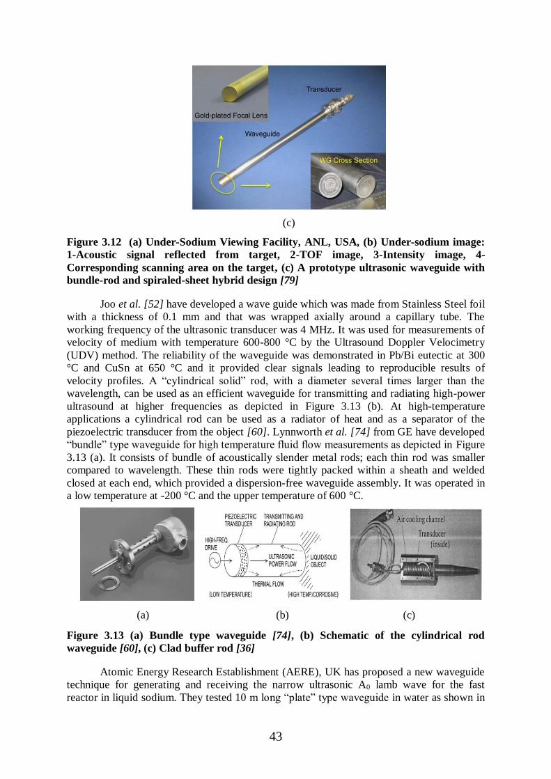
43
(c)
Figure 3.12 (a) Under-Sodium Viewing Facility, ANL, USA, (b) Under-sodium image:
1-Acoustic signal reflected from target, 2-TOF image, 3-Intensity image, 4-
Corresponding scanning area on the target, (c) A prototype ultrasonic waveguide with
bundle-rod and spiraled-sheet hybrid design [79]
Joo et al. [52] have developed a wave guide which was made from Stainless Steel foil
with a thickness of 0.1 mm and that was wrapped axially around a capillary tube. The
working frequency of the ultrasonic transducer was 4 MHz. It was used for measurements of
velocity of medium with temperature 600-800 °C by the Ultrasound Doppler Velocimetry
(UDV) method. The reliability of the waveguide was demonstrated in Pb/Bi eutectic at 300
°C and CuSn at 650 °C and it provided clear signals leading to reproducible results of
velocity profiles. A “cylindrical solid” rod, with a diameter several times larger than the
wavelength, can be used as an efficient waveguide for transmitting and radiating high-power
ultrasound at higher frequencies as depicted in Figure 3.13 (b). At high-temperature
applications a cylindrical rod can be used as a radiator of heat and as a separator of the
piezoelectric transducer from the object [60]. Lynnworth et al. [74] from GE have developed
“bundle” type waveguide for high temperature fluid flow measurements as depicted in Figure
3.13 (a). It consists of bundle of acoustically slender metal rods; each thin rod was smaller
compared to wavelength. These thin rods were tightly packed within a sheath and welded
closed at each end, which provided a dispersion-free waveguide assembly. It was operated in
a low temperature at -200 °C and the upper temperature of 600 °C.
(a) (b) (c)
Figure 3.13 (a) Bundle type waveguide [74], (b) Schematic of the cylindrical rod
waveguide [60], (c) Clad buffer rod [36]
Atomic Energy Research Establishment (AERE), UK has proposed a new waveguide
technique for generating and receiving the narrow ultrasonic A0 lamb wave for the fast
reactor in liquid sodium. They tested 10 m long “plate” type waveguide in water as shown in

44
Figure 3.14 (b) and obtained good SNR at low frequency (2 MHz) [39]. They also tested 2 m
long strip waveguide in water at ambient temperature and in liquid sodium at 400 °C and
achieved good SNR.
The Fast Reactor Development at Korea Atomic Energy Research Institute (KAERI)
has designed and developed a 10 m long plate-type ultrasonic waveguide sensor module as
shown Figure 3.14 (c) for under-sodium visual inspection of the in-vessel structures of the
reactor core in a sodium-cooled fast reactor. In the plate type waveguide sensor A0 leaky
Lamb wave was used for single mode generation in low frequency range. The liquid wedge
was used for the generation of A0 mode. To decrease the dispersion of echo signals, a comb
shaped transducer as shown in Figure 3.14 (a) was used with the strip held by a metal holder
[25, 39, 73]. The tone burst pulses were applied to minimize the dispersion characteristics of
the A0 mode leaky lamb wave. When the waveguide sensor was immersed in a liquid, the
waves created a leaky compression wave within a liquid via mode conversion and it was used
to measure the liquid sodium level [55]. A schematic of mode conversion, leaky wave
generation and propagation is shown in Figure 3.14 (d). The angle of radiation beam depends
on the product of the frequency and the plate thickness in the dispersive range of the A0
mode. So the control of beam steering was obtained by the “frequency tuning” method. This
technique has advantages to overcome the scanning limitation of the waveguides described
earlier. The C-scan imaging in under water experiment was carried out and provided a
resolution of 2 mm as shown in Figure 3.14 (g) [78]. The prototype waveguide was also
tested in liquid sodium at 200 °C using XYZ scanner (Figure 3.14 (e)) to obtain C-scan image
as shown in Figure 3.14 (h). In order to obtain effective refraction of the leaky longitudinal
wave into liquid sodium, thin beryllium layer was coated on the inner surface of waveguide
[75]. As sodium wetting depends on surface roughness, the wetting was improved by the
coating of the 0.02 µm micro-polished nickel layer on the outer surface of the waveguide.
From the C-scan under sodium experiment it was concluded that the prototype waveguide has
obtained SNR of over 10 dB and resolution of approximately 1 mm into sodium [81]. The
brazing technique was used to coat thin beryllium (Be) and nickel (Ni) layers on the radiation
surfaces of the transducer to improve the propagation of the ultrasonic waves into liquid
sodium. But the brazing technique decreases the signal sensitivity because it uses a filler
metal which acts as an obstacle to the ultrasonic wave propagation. To overcome this
problem, Kim et al. [56] have proposed a “diffusion” bonding technique to coat thin
beryllium and nickel layers on the transmitting surfaces of the transducers. The under-sodium
test of the 10 m long diffusion bonded waveguide sensor was also carried out and the
obtained SNR was around 16 dB with 0.5 mm resolution at 200 °C in liquid sodium. The
better surface defect detection having a precision of 0.3 mm in water was obtained by using
the dual waveguide sensor operated simultaneously as shown in Figure 3.14 (f) [54].
(a) (b)

45
(c) (d)
(e) (f)

46
(g)
(h)
Figure 3.14 (a) Comb shape based transducer element for waveguide [39], (b) Plate type
waveguide, UK [39], (c) 10 m plate waveguide with liquid wedge [78], (d) Ultrasonic
mode conversion, leaky wave generation and propagation using plate type waveguide
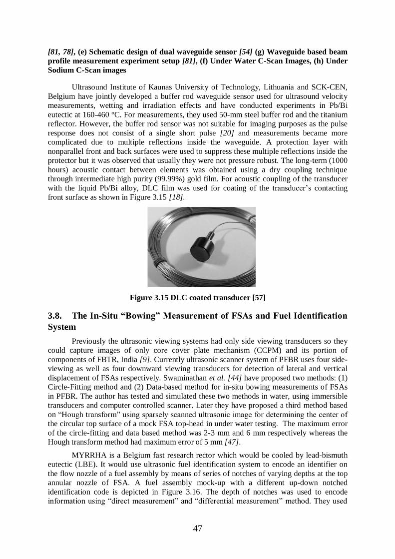
47
[81, 78], (e) Schematic design of dual waveguide sensor [54] (g) Waveguide based beam
profile measurement experiment setup [81], (f) Under Water C-Scan Images, (h) Under
Sodium C-Scan images
Ultrasound Institute of Kaunas University of Technology, Lithuania and SCK-CEN,
Belgium have jointly developed a buffer rod waveguide sensor used for ultrasound velocity
measurements, wetting and irradiation effects and have conducted experiments in Pb/Bi
eutectic at 160-460 °C. For measurements, they used 50-mm steel buffer rod and the titanium
reflector. However, the buffer rod sensor was not suitable for imaging purposes as the pulse
response does not consist of a single short pulse [20] and measurements became more
complicated due to multiple reflections inside the waveguide. A protection layer with
nonparallel front and back surfaces were used to suppress these multiple reflections inside the
protector but it was observed that usually they were not pressure robust. The long-term (1000
hours) acoustic contact between elements was obtained using a dry coupling technique
through intermediate high purity (99.99%) gold film. For acoustic coupling of the transducer
with the liquid Pb/Bi alloy, DLC film was used for coating of the transducer‟s contacting
front surface as shown in Figure 3.15 [18].
Figure 3.15 DLC coated transducer [57]
3.8. The In-Situ “Bowing” Measurement of FSAs and Fuel Identification
System
Previously the ultrasonic viewing systems had only side viewing transducers so they
could capture images of only core cover plate mechanism (CCPM) and its portion of
components of FBTR, India [9]. Currently ultrasonic scanner system of PFBR uses four side-
viewing as well as four downward viewing transducers for detection of lateral and vertical
displacement of FSAs respectively. Swaminathan et al. [44] have proposed two methods: (1)
Circle-Fitting method and (2) Data-based method for in-situ bowing measurements of FSAs
in PFBR. The author has tested and simulated these two methods in water, using immersible
transducers and computer controlled scanner. Later they have proposed a third method based
on “Hough transform” using sparsely scanned ultrasonic image for determining the center of
the circular top surface of a mock FSA top-head in under water testing. The maximum error
of the circle-fitting and data based method was 2-3 mm and 6 mm respectively whereas the
Hough transform method had maximum error of 5 mm [47].
MYRRHA is a Belgium fast research rector which would be cooled by lead-bismuth
eutectic (LBE). It would use ultrasonic fuel identification system to encode an identifier on
the flow nozzle of a fuel assembly by means of series of notches of varying depths at the top
annular nozzle of FSA. A fuel assembly mock-up with a different up-down notched
identification code is depicted in Figure 3.16. The depth of notches was used to encode
information using “direct measurement” and “differential measurement” method. They used

48
“Hamming code” based error correction code with parity bit for identification. In case of
multiple transducer failures, they have proposed a method based on solving a linear system
over Boolean variable to reconstruct the fuel Identification number. They have achieved
probability of reconstruction 100% in case of two transducer failures, 98% for three, 79% for
four and 20% for five failing transducers [16, 58, 59].
Figure 3.16 Fuel Identification Mockups
3.9. Sodium Removal for Sodium-Immersed Ultrasonic Transducers
After completion of sodium testing, it is essential to remove the residues of sodium
from the surface of the transducers to avoid the violent reaction of sodium with air when the
transducer assembly is taken out from the reactor vessel. Sodium removal from USUSS,
India was established by using WV–CO2 (Water Vapor- CO2) process and it took 125 hours
to complete the sodium removal campaign [68].

49
4. BEAMFORMING METHODS
Beamforming is a signal-processing technique which has multiple arrayed sensors for
transmissions/receptions used for various applications such as wireless communications,
radar, sonar and ultrasound. Beamforming activates directional or spatial selectivity of signal
transmission or reception. In medical/industrial ultrasound, beamforming is employed to
focus the echo signals received as reflections from different materials/structures. On the
transmit side, different beam patterns such as focusing of ultrasound are generated by
appropriately delaying echo signals arriving at different sensing elements to align echo
signals in a way that creates an isophase plane, and the receive beamformer creates a pattern
of beams pointing in the same direction by the same way as the delay pattern applied to the
transmitter. These aligned echoes are then summed coherently. This basic signal processing
principle is called a delay-and-sum function in the time domain.
Generally there are two types of beam forming methods which are used in ultrasonic
imaging applications: Analog beamforming and Digital beamforming. In both types of
systems, the signal received from the focal point from each channel are stored, time wise
lined up together and coherently summed. The main difference between analog and digital
beamformer is that the analog beamformer uses analog delay lines for delaying signals and an
adder for analog summation (before sampling), while in digital beamformer, analog signal is
sampled before addition, delayed and summed digitally. Analog beamformer requires only
one high speed and high resolution ADC while digital beamformer system needs high speed
and high resolution ADCs for each channels and it causes high power consumption due to
more number of ADCs and digital circuits. In digital beamformer, sampling rate of ADC
determines axial resolution and a finer phase delay channel to channel adjustment, but it may
not be possible to get very high speed ADC with high resolution and low power so they use
“digital interpolation” in beamforming to get finer delay resolution. In analog beamformer, a
number of analog delay taps determines resolution but the number of delay taps is limited in
analog delay lines and they have poor channel-to-channel matching in analog domain. Now a
days, digital beamforming technique is widely used because of several reasons like digital
domain has perfect channel-to-channel matching, multiple beams can be easily formed by
summing data from different locations in the high speed FIFOs, FIFOs can be very deep and
allow fine delay and systems can be more easily differentiated through software based system
[97, 98]. In digital beamforming, there are different methodologies used for imaging
applications such as phased array, synthetic aperture, sparse array processing. The detailed
comparisons of various beamforming methods have been published by [99, 100]. Reviews of
some of the beamforming methods that can be used for viewing in liquid sodium have been
elaborated as below:
4.1. Phased Array Imaging
Phased array beamformer uses mostly the “gold standard” algorithm, where all the
transducers are actively used in both transmit and receive mode. They enable the ultrasonic
beam to be focused and/or steered at desired depth electronically. Each array element is
excited by the same electronic pulse but with different time delay and by controlling the
delay time, the focal point and the steering angle can be controlled and normally these are
called “focusing” and “steering” behaviors correspondingly [101, 102]. This electronic
control of beam is useful when it is necessary to focus the beam at various points in a sample.
The two-dimensional image of the interior of a sample in a real time can be obtained by
steering the focal point rapidly. Song et al. [82] have developed a phased array system named
“PAULI” for NDT and flaw measurements in nuclear power plant. Ideal phased array

50
systems must have minimum main lobe width, no grating lobes and minimum side lobe
amplitude. The phased array element size influence on beam steering has been provided by
Wooh et al. [103]. Phased array must have element to element distance/pitch, less than half
of the wavelength of transducer element to eliminate grating lobes in the operating field zone.
The grating lobes are generated by ultrasonic pressure due to the even sampling across
transducer probe elements. In the far field, grating lobe is indistinguishable from the main
lobe, since all the array elements contribute to its formation with the same phase at a given
angular direction and reduces contrast and dynamic range of ultrasonic image. In beam
steering, grating lobes appear when the time delays are such that there are one or more other
directions in which the waves from the elements are an integral multiple of wavelengths and
also due to the violation of the spatial sampling criterion. So it can be stated that the grating
lobes cannot exist for any steering angle if the pitch distance is less than λ/2.
In liquid sodium, piezoelement is connected through coaxial cable of more than 10
meters length. If ultrasonic piezoelements with small dimension size and pitch which have
low capacitance are used in liquid sodium then the level of received signal will be reduced
several times due to high capacitance of the long length cable. At high temperature, the
coupling parameters of PZT are very sensitive to temperature fluctuations which can cause
the large amplitude and phase fluctuation in the received signal. The required half wave pitch
distance should be 0.45-0.18 mm for ultrasonic frequency of 2-5 MHz but very small
dimensions create serious problems during assembly and so it is challenging to design the
phased array transducers for imaging under liquid sodium [6]. Instead of using multi-element
phased array in molten metal for imaging, an optical lens based “Acousto-optical
registration” imaging method has been proposed which is based on coherent optical
interferometry [104]. Recently PNNL, USA has used phased array imaging method using
two matrix array each with 30 (10×3) elements for under water C-Scan imaging of target
[124].
4.2. Synthetic Aperture Imaging
The synthetic aperture technique was first developed for radar application as synthetic
aperture radar (SAR) and it is mainly based on “Delay and Sum” (DAS) based processing
algorithm. The synthetic aperture technique allows building virtual aperture by synthesizing
into smaller real apertures which results in improved lateral resolution along full penetration
depth without sacrificing the imaging frame rate [105]. The Synthetic Aperture Technique
has various types: (1) Synthetic Aperture Focusing (SAF), (2) Multi-element Synthetic
Aperture (M-SAF), (3) Synthetic Focusing (SF), (4) Synthetic Receive Aperture (SRA) and
(5) Synthetic Transmit Aperture (STA). SAF has high Lateral resolution compared to phased
array (PA). For SAF, grating lobes appear at half distance compared to PA so numbers of
grating lobes are double. SAF provides worst imaging quality among all described synthetic
aperture technique. M-SAF is better compared to SAF since energy is high for multi-element
and also has high frame rate. The M-SAF method provides higher electronic SNR and better
contrast resolution than conventional synthetic aperture techniques [106]. SRA requires
larger memory, only for data acquisition and provides better lateral resolution and contrast
dynamics. STA Provides higher frame rate for images, with same image quality as PA.
PNNL, USA has used real time synthetic aperture method for non destructive testing
of nuclear reactor components [122] but it was not used for under sodium imaging purpose.
Only Karasawa et al. [5], Japan have implemented and used a synthetic aperture focusing
technique (SAFT) for 3-D under sodium imaging in liquid sodium at 200 °C temperature by
using 36×36 matrix arrayed transducers. They have achieved circumferential resolution of <2
mm and axial resolution of <0.5 mm in liquid sodium environment.

51
4.3. Phased Sub-Array Imaging
The full phased array (PA) imaging method provides better ultrasonic image quality
but increases front-end hardware complexity. On the other hand conventional synthetic
aperture imaging has lower hardware complexity but has lower SNR hence poor image
quality. Johnson et al. [107, 108] have proposed a new coherent array imaging method called
“Phased Sub-Array” which reduces front-end hardware complexity compared to the phased
array at the cost of slightly reduction of SNR and provides image quality better than the
conventional synthetic aperture imaging.
4.4. Sparse Array Imaging The Sparse Array based design is used to optimize the number of elements (in both
transmitter and receiver array) by randomly placing elements against the dense array based
ultrasonic system while providing same performance. The randomly placed sparse array does
not have periodic sampling patterns and so they do not produce grating lobes in radiation
pattern. The “varnier” array [109] with higher contrast and one directional curved array [110]
can be used to reduce the side lobe peak compared to sparse array. The combination of a
sparse transmit array and synthetic aperture beamforming can also permit the development of
real-time 3-D imaging systems using mechanically scanned linear phased arrays [111].
4.5. Sampling Phased Array (SPA) Imaging A new phased array technique, called “Sampling Phased Array (SPA)” has been
developed by the Fraunhofer Institute for Non-Destructive Testing, Germany. In conventional
phased array system, as the number of sensors are increased the electronic control of focal
depth and steering angle will be significantly reduced and it also reduces the probability of
detection. In SPA, the returning ultrasonic echo signals from a single shot by single
transmitting transducer element are captured by every one of the receiving transducer
elements instead of using multiple shots by multiple transducers as like in conventional
phased array. This technique provides higher sensitivity for the inspection along with high
resolution which enables to perform quantitative NDT and increases the probability of
detection of small discontinuities in highly stressed materials [112, 113, 114, 115]. Since
SPA combines both phased array and synthetic aperture technique, SPA technique can be
used for the real time 3-D visualization of the inspection volume [116]. In addition, the
Sampling Phased Array technology offers improved detect-ability of defects and enhances
the ability of ultrasonic systems to inspect materials such as non-homogeneous anisotropic
materials which have poor inspect-ability compared to conventional phased array [113, 115].
4.6. Coded Excitation Imaging In ultrasound, axial resolution is improved by increasing the bandwidth of element,
which typically happens for higher center frequencies. On the other hand, the attenuation of
ultrasound typically increases as frequency increases, which cause decrement in penetration
depth. Therefore, there is a tradeoff between spatial resolution and penetration depth in
ultrasonic imaging. One way to increase the penetration depth without reducing axial
resolution is by increasing the excitation pulse amplitude. Other solution is to increase the
excitation pulse duration by using “coded excitation” technique which increases the total
transmitted energy. However, large signal duration causes reverse effect of decreasing the
axial resolution of the ultrasonic imaging system. In order to restore the axial resolution after
excitation, pulse compression is used. The main disadvantage of using coded excitation and
pulse compression would be the introduction of side lobes that can appear as false echoes in

52
an image. The introduction of range side lobes is a disadvantage for ultrasonic image because
it can reduce the contrast resolution. The main advantage of using coded excitation is the
improvement in SNR. This improvement in SNR results in greater depth of penetration hence
it increases contrast resolution. The linear frequency modulation (FM) based coded excitation
can be used to improve the contrast resolution of image by reducing the side lobes and by
enhancing SNR [117, 118, 119, 120, 121].

53
5. SIMULATION MODELING
Currently, there are many software based simulation models such as Field II [84, 85]
and k-wave [86] which are available for ultrasonic imaging purpose for industrial and
medical applications. Very few technical literatures are available for simulation of
propagation of acoustic waves in high temperature liquid metal/sodium environment. In
liquid sodium environment, the acoustic modeling is required for understanding and
predicting the ultrasonic waves which can get refracted, deflected, delayed and accelerated
depending upon the thermo-hydraulic conditions of the liquid sodium. The temperature
gradients of various FSAs and turbulent sodium flow are the two major sources of the
thermo-hydraulic characteristics. The sodium flow has different speed gradient which affects
the acoustics properties. Massacret et al. [87, 88] have proposed the “Ray Trace” model for
simulation of the deflected ultrasonic wave and “Gaussian Beam Summation” method for
measurement of the amplitude of the ultrasonic wave front at various time of propagation for
the thermometry application. For Structural Health Monitoring (SHM) applications in nuclear
reactor, Benjeddou et al. [89] have presented a 2D modeling of ultrasound thermometry with
SPECFEM simulation code. The acoustic computer model to simulate visualization of the
core of a nuclear reactor with the liquid Pb/Bi coolant has been made by Jasiūniené, Elena, et
al. [123]. The performed simulations demonstrated that the internal components of the
reactor can be identified from the reconstructed image and from that, their dimensions and
positions can be measured. Bilgunde et al [125, 126, 127] have worked on 2D Finite element
modeling of the piezoelectric material for the investigation of various piezoelectric
coefficients at high temperature in COMSOL software package. The transducer response has
been computed in liquid sodium at elevated temperature and in water at room temperature as
a reference case. They have validated the simulated reference case with experimented data.
Recently, Nagaso et al [129] have presented a 2D Numeric modeling based on spectral-
element method in the time domain to analyze variation in time of flight data due to
temperature changes in a sodium fluid medium. They illustrated the sensitivity of an
ultrasonic thermometry method to a relatively weak temperature change in a SPECFEM
software package. With a static temperature profile, they conclude that a temperature
variation of about 1% of the average temperature (about 5 °C) could be detected and it
induces a time of shift of about 68 ns. There is a large scope to further carry out research and
development in the field of simulation and modeling for sodium cooled fast breeder reactors.
54
6. CONCLUSIONS
In this report, different transducer assembly materials have been discussed which
were utilized and sustained in liquid sodium environment from all over world for SFRs. The
different designs and techniques have been reviewed related to ultrasonic imaging/viewing
systems for under sodium imaging for fast reactors. The various possible beamforming
methods which may be used for high temperature under sodium imaging have been
discussed. The brief review regarding some simulation models have also been elaborated.
For perfect wetting of the transducer assembly in liquid sodium, the faceplate
diaphragm material and surface roughness play a vital role. The suitable materials for
transducer faceplate are namely polished nickel, nickel alloy, thin gold coating and diamond
like carbon (DLC) coating. However, the problem of wetting has not been solved completely.
For certain low temperature applications, the PZT and Lithium Niobate material have been
used, but for high temperature applications the suitable materials such as Bismuth Titanate
and Lead metaniobate are needed. The other new materials have been tried for very high
temperature experiments such as AIN and YCOB. YCOB crystal is capable of ultrasonic
transduction up to 1000 °C. The matching of the thermal coefficient of expansion for
piezoelements and faceplate/backing materials is very important for perfect acoustic
transmission in liquid metal. Generally for high temperature bonding/coupling application
dry and/or liquid couplants are not used. Currently the diffusion bonding with gold-to-gold,
silver-to-silver bonding and high temperature epoxies are widely used for harsh environment
applications. For housing of transducer and related components, Stainless Steel and Nickel
have been employed as they can maintain their performance in high temperature
environment. With reference to past and current literatures, designers have used mineral
insulated (MI) cables for the transmission of electrical signal to/from the transducer element
because of its low capacitance, suitability for high temperature environment and good
radiation resistance characteristics.
The different ultrasonic imaging methods have been reviewed and it is concluded that
there is no single optimum and suitable high speed (or real time) technique which has been
used for high temperature under sodium ultrasonic imaging. The matrix based 2-D array
ultrasonic imaging system was only been used in liquid sodium by Japan [5] and they have
achieved appreciable image resolution. However, they could not convert the prototype system
into real time imaging system. As a result, there is no commercially available “real time”
system which can operate in high temperature for liquid sodium application. Currently
waveguide based technology is widely exploited for under sodium imaging purpose because
of its many fold advantages as mentioned in the report. A prototype which is a combination
of bundle-rod and spiraled-sheet design and a plate type waveguide provide very good
resolution and acceptable SNR in liquid sodium environment.
The “Digital” beamforming is a suitable method for ultrasonic receiver as described in
the report. The linear array/phased array (PA) system does not provide proper performance
because of the generation of grating lobes due to the large element to element (pitch)
distance. But performance can be enhanced by minimizing pitch distances and side lobes.
The synthetic Aperture focusing technique for under sodium imaging was only used by Japan
[5]. The further imaging quality can be enhanced by using the various methods such as
SAFT, Sampling Phased Array and Sparse Array based method as discussed earlier in
Section no. 4.
Currently, it is not possible to make any conclusion regarding the simulation
modeling of ultrasonic behavior under the high temperature gradient and turbulent liquid
sodium flow environment due to the availability of very few literature references.

55
This review report on Under Sodium Ultrasonic Viewing for Fast Breeder Reactors
has covered almost all the literatures from year 1967 to March-2016 related to the Ultrasonic
Imaging techniques, Ultrasonic Viewing methodologies, high temperature transducers,
experiments and systems, which will enable designers or users to exploit right solution for
their application.
Acknowledgement
Authors are grateful to Dr.Kallol Roy, Chairman & Managing Director (CMD),
Bharatiya Nabhikiya Vidyut Nigam Limited (BHAVINI), Kalpakkam, TamilNadu- 603102
for his technical guidance for the preparation of this review report. Authors are thankful to
Shri. Debashis Das, Head, Electronics Division, BARC and Shri.Y.S.Mayya, Director, E&I
Group, BARC for support, guidance and permission to publish this report.
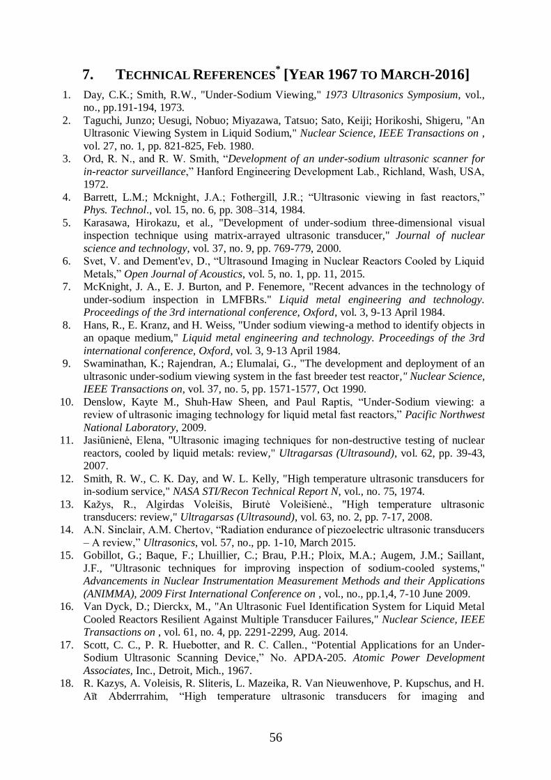
56
7. TECHNICAL REFERENCES* [YEAR 1967 TO MARCH-2016]
1. Day, C.K.; Smith, R.W., "Under-Sodium Viewing," 1973 Ultrasonics Symposium, vol.,
no., pp.191-194, 1973.
2. Taguchi, Junzo; Uesugi, Nobuo; Miyazawa, Tatsuo; Sato, Keiji; Horikoshi, Shigeru, "An
Ultrasonic Viewing System in Liquid Sodium," Nuclear Science, IEEE Transactions on ,
vol. 27, no. 1, pp. 821-825, Feb. 1980.
3. Ord, R. N., and R. W. Smith, “Development of an under-sodium ultrasonic scanner for
in-reactor surveillance,” Hanford Engineering Development Lab., Richland, Wash, USA,
1972.
4. Barrett, L.M.; Mcknight, J.A.; Fothergill, J.R.; “Ultrasonic viewing in fast reactors,”
Phys. Technol., vol. 15, no. 6, pp. 308–314, 1984.
5. Karasawa, Hirokazu, et al., "Development of under-sodium three-dimensional visual
inspection technique using matrix-arrayed ultrasonic transducer," Journal of nuclear
science and technology, vol. 37, no. 9, pp. 769-779, 2000.
6. Svet, V. and Dement'ev, D., “Ultrasound Imaging in Nuclear Reactors Cooled by Liquid
Metals,” Open Journal of Acoustics, vol. 5, no. 1, pp. 11, 2015.
7. McKnight, J. A., E. J. Burton, and P. Fenemore, "Recent advances in the technology of
under-sodium inspection in LMFBRs." Liquid metal engineering and technology.
Proceedings of the 3rd international conference, Oxford, vol. 3, 9-13 April 1984.
8. Hans, R., E. Kranz, and H. Weiss, "Under sodium viewing-a method to identify objects in
an opaque medium," Liquid metal engineering and technology. Proceedings of the 3rd
international conference, Oxford, vol. 3, 9-13 April 1984.
9. Swaminathan, K.; Rajendran, A.; Elumalai, G., "The development and deployment of an
ultrasonic under-sodium viewing system in the fast breeder test reactor," Nuclear Science,
IEEE Transactions on, vol. 37, no. 5, pp. 1571-1577, Oct 1990.
10. Denslow, Kayte M., Shuh-Haw Sheen, and Paul Raptis, “Under-Sodium viewing: a
review of ultrasonic imaging technology for liquid metal fast reactors,” Pacific Northwest
National Laboratory, 2009.
11. Jasiūnienė, Elena, "Ultrasonic imaging techniques for non-destructive testing of nuclear
reactors, cooled by liquid metals: review," Ultragarsas (Ultrasound), vol. 62, pp. 39-43,
2007.
12. Smith, R. W., C. K. Day, and W. L. Kelly, "High temperature ultrasonic transducers for
in-sodium service," NASA STI/Recon Technical Report N, vol., no. 75, 1974.
13. Kažys, R., Algirdas Voleišis, Birutė Voleišienė., "High temperature ultrasonic
transducers: review," Ultragarsas (Ultrasound), vol. 63, no. 2, pp. 7-17, 2008.
14. A.N. Sinclair, A.M. Chertov, “Radiation endurance of piezoelectric ultrasonic transducers
– A review,” Ultrasonics, vol. 57, no., pp. 1-10, March 2015.
15. Gobillot, G.; Baque, F.; Lhuillier, C.; Brau, P.H.; Ploix, M.A.; Augem, J.M.; Saillant,
J.F., "Ultrasonic techniques for improving inspection of sodium-cooled systems,"
Advancements in Nuclear Instrumentation Measurement Methods and their Applications
(ANIMMA), 2009 First International Conference on , vol., no., pp.1,4, 7-10 June 2009.
16. Van Dyck, D.; Dierckx, M., "An Ultrasonic Fuel Identification System for Liquid Metal
Cooled Reactors Resilient Against Multiple Transducer Failures," Nuclear Science, IEEE
Transactions on , vol. 61, no. 4, pp. 2291-2299, Aug. 2014.
17. Scott, C. C., P. R. Huebotter, and R. C. Callen., “Potential Applications for an Under-
Sodium Ultrasonic Scanning Device,” No. APDA-205. Atomic Power Development
Associates, Inc., Detroit, Mich., 1967.
18. R. Kazys, A. Voleisis, R. Sliteris, L. Mazeika, R. Van Nieuwenhove, P. Kupschus, and H.
Aït Abderrrahim, “High temperature ultrasonic transducers for imaging and
57
measurements in a liquid Pb/Bi eurectic alloy,” IEEE Trans. Ultrason., Ferroelectr.,
Freq. Control, vol. 52, no. 4. pp. 525–537, Apr. 2005.
19. Patel, N. D., S. X. Fulford, and P. S. Nicholson, "High frequency-high temperature
ultrasonic transducers," Review of Progress in Quantitative Nondestructive Evaluation,
Springer US, vol., no., pp. 823-828, 1990.
20. Kazys, R.; Voleisis, A.; Sliteris, R.; Voleisiene, B.; Mazeika, L.; Kupschus, P.H.;
Abderrahim, H.A., "Development of Ultrasonic Sensors for Operation in a Heavy Liquid
Metal," Sensors Journal, IEEE , vol. 6, no. 5, pp. 1134-1143, Oct. 2006.
21. Yuu Ono; Kobayashi, M.; Moisan, O.; Cheng-Kuei Jen, "High-temperature and
broadband immersion ultrasonic probes," Sensors Journal, IEEE, vol. 6, no. 3, pp. 580-
587, June 2006.
22. Augereau, Franck P., et al. "Effect of intense neutron dose radiation on piezoceramics,"
Journal of the Acoustical Society of America, vol. 123, no. 5, pp. 3928, 2008.
23. Primak, William, T. T. Anderson, and S. L. Halverson, "Ionizing radiation effects in
lithium niobate," Nuclear Technology, vol. 10, no. 1, pp. 76-84, 1971.
24. Halverson, S. L., et al., "Radiation exposure of a lithium niobate crystal at high
temperatures," Nuclear Science, IEEE Transactions on, vol. 17, no. 6, pp. 335-340, 1970.
25. Watkins R. D., L. M. Barrett, and J. A. McKnight, “Ultrasonic waveguide for use in the
sodium coolant of fast reactors,” Nuclear. Enegy, vol. 27, no. 4, pp. 85-89, 1988.
26. Fothergill, J. R., P. Willis, and S. Waywell, "Development of high-temperature ultrasonic
transducers for under-sodium viewing applications," British Journal of Non-Destructive
Testing, vol. 31, no. 5, pp. 259-264, 1989.
27. Holbert, Keith, et al., "Response of piezoelectric acoustic emission sensors to gamma
radiation," ESA Special Publication, vol. 536, no., pp., 2004.
28. Kažys, R., et al., "Ultrasonic transducers for high temperature applications in accelerator
driven reactors," 2003.
29. Ford J. V., James D. W., “Review of fast reactor in-service inspection practice,” EU
Publications, 1996.
30. Zhang, Shujun, et al., "Characterization of piezoelectric single crystal YCa4O (BO3) 3 for
high temperature applications," Applied Physics Letters, vol. 92, no. 20, pp. 202905-
202905, 2008.
31. Robert Hill, "US Status of Fast Reactor Research and Technology." Argonne National
Laboratory, Nuclear Engineering Division, 2012.
32. Baba, Atsushi, Clifford T. Searfass, and Bernhard R. Tittmann, "High temperature
ultrasonic transducer up to 1000 C using lithium niobate single crystal," Applied Physics
Letters, vol. 97, no. 23, pp. 232901, 2010.
33. Parks, D. A., B. T. Reinhardt, and B. R. Tittmann, "Selecting a radiation tolerant
piezoelectric material for nuclear reactor applications," Review of Progress in
Quantitative Nondestructive Evaluation: volume 32, AIP Publishing, vol. 1511, no. 1,
2013.
34. Wang, K., et al., "Ultrasonic Waveguide Transducer for Under-Sodium Viewing in SFR,"
International Journal of Nuclear Energy Science and Engineering 2, no. ANL/NE/JA-
72910, 2012.
35. Wang, K., et al. "Development of a Novel Ultrasonic Waveguide Transducer for
Under‐Sodium Viewing." Review of Progress in Quantitative Nondestructive Evaluation:
Volume 30A; Volume 30B, AIP Publishing, vol. 1335, no. 1, 2011.
36. Ihara, I., C-K. Jen, and D. Ramos França, "Ultrasonic imaging, particle detection, and V
(z) measurements in molten zinc using focused clad buffer rods," Review of scientific
instruments, vol. 71, no. 9, pp. 3579-3586, 2000.

58
37. Yuu Ono; Moisan, O.; Cheng-Kuei Jen, "Ultrasonic techniques for imaging and
measurements in molten aluminum," Ultrasonics, Ferroelectrics, and Frequency Control,
IEEE Transactions on , vol. 50, no. 12, pp. 1711-1721, Dec. 2003.
38. Ono, Y.; Moisan, J.-F.; Jen, C.K.; Franca, D.R., "Development of ultrasonic techniques
with buffer rod in molten aluminum," Ultrasonics Symposium, 2002. Proceedings. 2002
IEEE , vol. 1, no., pp. 805-810, 8-11 Oct. 2002.
39. Watkins, R. D., et al., "A proposed method for generating and receiving narrow beams of
ultrasound in the fast reactor liquid sodium environment," Ultrasonics, vol. 20, no. 1, pp.
7-12, 1982.
40. F. Baque,"Review of in-service inspection and repair technique developments for French
liquid metal fast reactors," Nuclear technology, vol. 150, no. 1, pp. 67-78, 2005.
41. Lhuillier, C.; Marchand, B.; Augem, J.-M.; Sibilo, J.; Saillant, J.-F., "Generation IV
nuclear reactors: Under sodium ultrasonic transducers for Inspection and Surveillance,"
Advancements in Nuclear Instrumentation Measurement Methods and their Applications
(ANIMMA), 2013 3rd International Conference on , vol., no., pp. 1-6, 23-27 June 2013.
42. Baqué, François, et al.,"Development of Tools, Instrumentation and Codes for Improving
Periodic Examination and Repair of SFRs," Science and Technology of Nuclear
Installations 2012, 2012.
43. Lhuillier, C.; Descombin, O.; Baque, F.; Marchand, B.; Saillant, J.F.; Augem, J.M., "In
sodium tests of ultrasonic transducers," Advancements in Nuclear Instrumentation
Measurement Methods and their Applications (ANIMMA), 2011 2nd International
Conference on , vol., no., pp. 1-7, 6-9 June 2011.
44. Swaminathan, K.; Asokane, C.; Sylvia, J.I.; Kalyanasundaram, P.; Swaminathan, P., "An
Ultrasonic Scanning Technique for In-Situ `Bowing' Measurement of Prototype Fast
Breeder Reactor Fuel Sub-Assembly," Nuclear Science, IEEE Transactions on , vol. 59,
no. 1, pp. 174-181, Feb. 2012.
45. Patankar, V. H., et al., "Sweep-arm Scanning Technique for Core-mapping of Fuel Sub-
assemblies of Fast Breeder Reactor," Asia Pacific Conference on Non-Destructive Testing
(14th APCNDT), Mumbai, 18-22 November, 2013.
46. Sylvia, J. I., et al., "Ultrasonic imaging of projected components of PFBR," Nuclear
Engineering and Design, vol., no. 258, pp. 266-274, 2013.
47. Swaminathan, K.; Swaminathan, P., "Hough Transform Method for Determining the Fuel
Sub-Assembly's In-Situ „Bow‟ in Breeder Reactor Using Its Sparsely Scanned Ultrasonic
Image," Nuclear Science, IEEE Transactions on , vol. 60, no. 4, pp. 3033-3039, Aug.
2013.
48. Patankar, V. H., et al., "Instrumentation & Control System For Under Sodium Ultrasonic
Scanner of PFBR," Proceedings of the National Seminar & Exhibition on Non-
Destructive Evaluation NDE 2011, 8-10 December 2011.
49. Patankar, V. H., et al., "Design and Development of Automated Ultrasonic
Instrumentation for Detection of Growth and Bowing of Under-Sodium Fuel
Subassemblies of FBR," Proceedings of NDE 2009 Seminar, Trichy, TN, 10-12 Dec.
2009.
50. Patankar, V. H., et al., "Under Sodium Ultrasonic Imaging System for PFBR" BARC
Newsletter JAN-FEB2014, vol., no. 336, pp. 18-24, 2014.
51. Wessels, J., "Inservice inspection of the reactor block of sodium-cooled fast breeder
reactors," Nuclear engineering and design, vol. 130, no. 1, pp. 33-42, 1991.
52. Eckert, S., G. Gerbeth, and V. I. Melnikov, "Velocity measurements at high temperatures
by ultrasound Doppler velocimetry using an acoustic wave guide," Experiments in fluids,
vol. 35, no. 5, pp. 381-388, 2003.

59
53. Inoue, T., Iwata, K., Kobayashi, M., "High temperature immersion ultrasonic probes,"
Ultrasonics Symposium (IUS), 2013 IEEE International, pp. 469, 470, 21-25, July 2013.
54. Joo, Young-Sang, et al., "Dual Ultrasonic Waveguide Sensor for the Detection of Surface
Defects," Transactions of the Korean Nuclear Society Autumn Meeting, PyeongChang,
Korea, 30-31 October 2008.
55. Joo, Young-Sang, and Jae-Han Lee, "Liquid Level Measurement Technique using
Ultrasonic Waveguide Sensor," Transactions of the Korean Nuclear Society Spring
Meeting, Chuncheon, Korea, 25-26 May 2006.
56. Kim, Sang-Hwal, Chang-Gyu Park, and Young-Sang Joo, "Performance Test of a
Diffusion Bonded Waveguide Sensor for Under-Sodium Visualization," Transactions of
the Korean Nuclear Society Spring Meeting, Jeju, Korea, 29-30 May 2014.
57. Kazys, R., et al., "Research and development of radiation resistant ultrasonic sensors for
quasi-image forming systems in a liquid lead-bismuth," Ultragarsas (Ultrasound), vol.
62, no. 3, pp. 7-15, 2006.
58. Dierckx, M.; Van Dyck, D.; Vermeeren, L.; Bogaerts, W., "Research Towards Ultrasonic
Systems to Assist In-Vessel Manipulations in Liquid Metal Cooled Reactors," Nuclear
Science, IEEE Transactions on , vol. 61, no. 4, pp. 2024-2033, Aug. 2014.
59. Dierckx, M.; Van Dyck, D., "Ultrasound in lead-bismuth eutectic," Advancements in
Nuclear Instrumentation Measurement Methods and their Applications (ANIMMA), 2011
2nd International Conference on , vol., no., pp. 1-6, 6-9 June 2011.
60. Hatano, Hajime, "Waveguide for transmitting and radiating high-frequency, high-power
ultrasound using higher mode vibrations of a cylindrical rod," Ultrasonics, Ferroelectrics,
and Frequency Control, IEEE Transactions on , vol. 52, no. 4, pp. 518-524, April 2005.
61. Bond, Leonard J., et al., "Materials issues in high temperature ultrasonic transducers for
under-sodium viewing," Review of Progress in Quantitative Nondestructive Evaluation
Volume 31, AIP Publishing, vol. 1430, no. 1. 2012.
62. Qiang Xue; Stanton, M.; Elfbaum, G., "A high temperature and broadband immersion 1-3
piezo-composite transducer for accurate inspection in harsh environments," Ultrasonics,
2003 IEEE Symposium on , vol. 2, no., pp. 1372-1375, 5-8 Oct. 2003.
63. Rehman, A. U., C. K. Jen, and I. Ihara, "Ultrasonic probes for high temperature
immersion measurements," Measurement Science and Technology, vol. 12, no. 3, pp. 306,
2001.
64. Parks, D.A.; Shujun Zhang; Tittmann, B.R., "High-temperature (>500 °C) ultrasonic
transducers: an experimental comparison among three candidate piezoelectric materials,"
Ultrasonics, Ferroelectrics, and Frequency Control, IEEE Transactions on , vol. 60, no.
5, pp. 1010-1015, May 2013.
65. Holbert, K.E.; Sankaranarayanan, S.; McCready, S.S., "Response of lead metaniobate
acoustic emission sensors to gamma irradiation," Nuclear Science, IEEE Transactions on
, vol. 52, no. 6, pp. 2583-2590, Dec. 2005.
66. Gubinyi, Z., et al., "Electrical properties of PZT piezoelectric ceramic at high
temperatures," Journal of Electroceramics, vol. 20, no. 2, pp. 95-105, 2008.
67. Tittmann, Bernhard R., David A. Parks, and Shujun O. Zhang, "High Temperature
Piezoelectrics-A Comparison," 13th Intl Symposium on Nondestructive Characterization
of Materials (NDCM-XIII), 2013.
68. Raj, S. Ignatius Sundar, et al., "Sodium removal from sodium wetted under sodium ultra
sonic scanner," Nuclear Engineering and Design, vol. 254, pp. 120-128, 2013.
69. Daw, J.; Tittmann, B.; Reinhardt, B.; Kohse, G.; Ramuhalli, P.; Montgomery, R.; Chien,
H.-T.; Villard, J.-F.; Palmer, J.; Rempe, J., "Irradiation Testing of Ultrasonic
Transducers," Nuclear Science, IEEE Transactions on , vol. 61, no. 4, pp. 2279-2284,
Aug. 2014.

60
70. Holbert, Keith, et al., "Response of piezoelectric acoustic emission sensors to gamma
radiation." ESA Special Publication, vol. 536, 2004.
71. Sobolev, Vitaly, "Database of thermophysical properties of liquid metal coolants for
GEN-IV," SCK-CEN, Scientific Report BLG-1069, 2010.
72. Rajendran, A., et al., "Development of an ultrasonic under-sodium scanner for the fast
breeder test reactor," Trends in NDE science and technology: proceedings of the
fourteenth world conference on NDT, vol. 2, 1996.
73. Asokane, C., et al., “Ultrasonic wave-guide for high temperature sodium applications,"
Proceedings of national symposium on nuclear instrumentation-2004, 2004.
74. Lynnworth, L.C.; Yi Liu; Umina, J.A., "Extensional bundle waveguide techniques for
measuring flow of hot fluids," Ultrasonics, Ferroelectrics, and Frequency Control, IEEE
Transactions on , vol. 52, no. 4, pp. 538-544, April 2005.
75. Joo, Young-Sang, et al., "Effects of beryllium coating layer on performance of the
ultrasonic waveguide sensor," Ultrasonics, vol. 53, no. 2, 387-395, 2013.
76. Griffin, J.W.; Posakony, G.J.; Harris, R.V.; Baldwin, D.L.; Jones, A.M.; Bond, L.J.,
"High temperature ultrasonic transducers for in-service inspection of liquid metal fast
reactors," Ultrasonics Symposium (IUS), 2011 IEEE International , vol., no., pp. 1924-
1927, 18-21 Oct. 2011.
77. Holbert, Keith et al., "Response of piezoelectric acoustic emission sensors to gamma
radiation," ESA Special Publication, vol. 536, no., pp., 2004.
78. Joo Y.S., C.G. Park, J.B. Kim and S.H. Lim, “Development of Ultrasonic Waveguide
Sensor for Under-sodium Inspection in a Sodium-cooled Fast Reactor,” NDT&E
International, vol. 44, no. 2, pp. 239-246, 2011.
79. Ke Wang, Hual-Te Chien, Thomas W. Elmer, William P. Lawrence, David M. Engel,
Shuh-Haw Sheen, “Development of ultrasonic waveguide techniques for under-sodium
viewing,” NDT & E International, vol. 49, no., pp. 71-76, July 2012.
80. Sheen, S. H. et al., “Linear-array ultrasonic waveguide transducer for under sodium
viewing,” No. ANL-GENIV-178. Argonne National Laboratory (ANL), 2010.
81. Hoe-Woong Kim, Young-Sang Joo, Chang-Gyu Park, Jong-Bum Kim, Jin-Ho Bae,
“Ultrasonic Imaging in Hot Liquid Sodium Using a Plate-Type Ultrasonic Waveguide
Sensor,” Journal of Nondestructive Evaluation, vol. 33, no. 4, pp. 676-683, December
2014.
82. Sung-Jin Song, Hyeon Jae Shin, You Hyun Jang, “Development of an ultra sonic phased
array system for nondestructive tests of nuclear power plant components, Nuclear
Engineering and Design,” vol. 214, no. 1, pp. 151-161, May 2002.
83. Karpelson, Alex, and Mike Trelinski, "Operation of Highly Focussed Immersion
Ultrasonic Transducers at Elevated Temperatures," Journal of Nondestructive Testing,
vol. 9, no. 12, 2004.
84. Jensen, Jørgen Arendt, "Field: A program for simulating ultrasound systems," 10th
nordicbaltic conference on biomedical imaging, vol. 4, no. 1, pp. 351-353, 1996.
85. Jensen, J.A., "Simulation of advanced ultrasound systems using Field II," Biomedical
Imaging: Nano to Macro, 2004. IEEE International Symposium on, vol., no., pp. 636-
639, 15-18 April 2004.
86. Anderson, Martin E., and Gregg E. Trahey, "A seminar on k-space applied to medical
ultrasound," Department of Biomedical Engineering, Duke University, 2000.
87. Massacret, N., et al., "Modelling of ultrasonic propagation in turbulent liquid sodium with
temperature gradient," Journal of Applied Physics, vol. 115, no. 20, pp. 204905, 2014.
88. Massacret, N., et al., "Simplified modeling of liquid sodium medium with temperature
and velocity gradient using real thermal-hydraulic data. Application to ultrasonic

61
thermometry in sodium fast reactor," Review of Progress in Quantitative Nondestructive
Evaluation: Volume 32, AIP Publishing, vol. 1511, no. 1, pp., 2013.
89. S. Benjeddou, J. Moysan, N. Massacret, M.A. Ploix, J.P. Jeannot, “Numerical simulation
of the temperature measurement by ultrasonic method in an environment representative of
the core of SFR,” 21ème Congrès Français de Mécanique, Bordeaux, 2013.
90. Drinkwater, Bruce W., and Paul D. Wilcox, "Ultrasonic arrays for non-destructive
evaluation: A review," NDT & E International, vol. 39, no. 7, pp. 525-541, 2006.
91. Bond, L.J.; Punjani, M., "Review of some recent advances in quantitative ultrasonic
NDT," Physical Science, Measurement and Instrumentation, Management and Education
- Reviews, IEE Proceedings, vol. 131, no. 4, pp. 265-274, June 1984.
92. Kumar, Dalgobind Mahto, "Recent Trends in Industrial and other Engineering
Applications of Non Destructive Testing: A Review," Global Journal of Researches in
Engineering, vol. 13, no. 3, pp., 2013.
93. Mineral Insulated Cable. [Online]. Available: http://www.micable.com/
94. Raj, Baldev, et al., "Development of fuels and structural materials for fast breeder
reactors." Sadhana, vol. 27, no. 5, pp. 527-558, 2002.
95. Mannan, S. L., et al., "Selection of materials for prototype fast breeder
reactor." Transactions-Indian Institute of MetalsI, vol. 56, no. 2, pp. 155-178, 2003.
96. “Structural Materials for Liquid Metal Cooled Fast Reactor Fuel Assemblies Operational
Behaviour,” International Atomic Energy Agency, Division of Nuclear Fuel Cycle and
Waste Technology, International Atomic Energy Agency (IAEA),Vienna, Austria, 2012.
97. Brunner, Eberhard, "How ultrasound system considerations influence front-end
component choice," Analog Dialogue, vol. 36, no. 3, pp. 1-4, 2002.
98. Brunner, Eberhard, “Ultrasound System Considerations and their Impact on Front-End
Components,” Analog Devices, vol. 36, no., pp., 2002.
99. Mucci, Ronald A., "A comparison of efficient beamforming algorithms," Acoustics,
Speech and Signal Processing, IEEE Transactions on , vol. 32, no. 3, pp. 548-558, Jun
1984.
100. Vasudevan, Sunil, “Ultrasonic Digital Beamformation: A Comparative Study,” Master
Thesis, McGill University, Canada, 1998.
101. Von Ramm, Olaf T.; Smith, S.W., "Beam Steering with Linear Arrays," Biomedical
Engineering, IEEE Transactions on, vol. BME-30, no. 8, pp. 438-452, Aug. 1983.
102. Azar, L., Y. Shi, and S-C. Wooh. "Beam focusing behavior of linear phased arrays." NDT
& E International, vol. 33, no. 3, pp. 189-198, 2000.
103. Wooh, Shi-Chang, and Yijun Shi. "Influence of phased array element size on beam
steering behavior." Ultrasonics, vol. 36, no. 6, pp. 737-749, 1998.
104. Bouchard, R.; Sahin, O.; Emelianov, S., "Ultrasound-guided photoacoustic imaging:
current state and future development," Ultrasonics, Ferroelectrics, and Frequency
Control, IEEE Transactions on , vol. 61, no. 3, pp. 450-466, March 2014.
105. Nowicki, Andrzej, and Barbara Gambin, "Ultrasonic Synthetic Apertures: Review,"
Archives of Acoustics, vol. 39, no. 4, pp. 427-438, 2014.
106. Karaman, Mustafa; Pai-Chi Li; O'Donnell, M., "Synthetic aperture imaging for small
scale systems," Ultrasonics, Ferroelectrics, and Frequency Control, IEEE Transactions
on , vol. 42, no. 3, pp. 429-442, May 1995.
107. Johnson, J.A.; Karaman, Mustafa; Khuri-Yakub, B.T., "Coherent-array imaging using
phased subarrays. Part I: basic principles," Ultrasonics, Ferroelectrics, and Frequency
Control, IEEE Transactions on , vol. 52, no. 1, pp. 37-50, Jan. 2005.
108. Johnson, J.A.; Oralkan, O.; Ergun, S.; Demirci, U.; Karaman, Mustafa; Khuri-Yakub,
B.T., "Coherent array imaging using phased subarrays. Part II: simulations and

62
experimental results," Ultrasonics, Ferroelectrics, and Frequency Control, IEEE
Transactions on , vol. 52, no. 1, pp. 51-64, Jan. 2005.
109. S.I. Nikolov and J.A. Jensen, “Application of different spatial sampling patterns for
sparse array transducer design,” Ultrasonics, vol. 37, no. 10, pp. 667–671, 2000.
110. J. E. Kirkebø, A. Austeng, "Improved Beamforming Using Curved Sparse 2D Arrays in
Ultrasound," Ultrasonics, vol. 46, no. 2, pp. 119-128, May 2007.
111. Lockwood, G.R.; Talman, J.R.; Brunke, S.S., "Real-time 3-D ultrasound imaging using
sparse synthetic aperture beamforming," Ultrasonics, Ferroelectrics, and Frequency
Control, IEEE Transactions on , vol.45, no. 4, pp. 980-988, July 1998.
112. Ramanan, Sridaran Venkat, et al., "Quantitative non-destructive evaluation of cfrp
components by sampling phased array," Proceedings of the International Symposium on
NDT in Aerospace, Hamburg, Germany, 2010.
113. Bulavinov, A., et al., "11. Ultrasonic Sampling Phased Array Testing as a Replacement
for X-ray Testing of Weld Joints in Ship Construction," Miscellaneous Problems in
Maritime Navigation, Transport and Shipping: Marine Navigation and Safety of Sea
Transportation ,vol. 91, 2011.
114. Verkooijen, J., and A. Boulavinov., "Sampling phased array a new technique for
ultrasonic signal processing and imaging," Insight-Non-Destructive Testing and
Condition Monitoring, vol. 50, no. 3, pp. 153-157, 2008.
115. Verkooijen, Jan, Andrey Boulavinov, and Ramzi Beidas, "Sampling phased array, a new
technique for ultrasonic signal processing and imaging now available to industry,"
ECNDT, Berlin, 2006.
116. Pudovikov, Sergey, Andrey Bulavinov, and Roman Pinchuk, "Innovative ultrasonic
testing (UT) of nuclear components by sampling phased array with 3D visualization of
inspection results," DGZfP Proceedings BB, vol. 125, no., pp., 2010.
117. Chiao, R.Y.; Xiaohui Hao, "Coded excitation for diagnostic ultrasound: a system
developer's perspective," Ultrasonics, Ferroelectrics, and Frequency Control, IEEE
Transactions on , vol. 52, no. 2, pp. 160-170, Feb. 2005.
118. Takeuchi, Y., "An investigation of a spread energy method for medical ultrasound
systems: Part one: Theory and investigation," Ultrasonics, vol. 17, no. 4, pp. 175-182,
1979.
119. Cowell, D. M. J., and S. Freear., "Quinary excitation method for pulse compression
ultrasound measurements," Ultrasonics, vol. 48, no. 2, pp. 98–108, 2008.
120. Misaridis, T.; Jensen, J.A., "Use of modulated excitation signals in medical ultrasound.
Part I: basic concepts and expected benefits," Ultrasonics, Ferroelectrics, and Frequency
Control, IEEE Transactions on, vol. 52, no. 2, pp. 177-191, Feb. 2005.
121. Misaridis, T.; Jensen, J.A., "Use of modulated excitation signals in medical ultrasound.
Part II: design and performance for medical imaging applications," Ultrasonics,
Ferroelectrics, and Frequency Control, IEEE Transactions on , vol. 52, no.2, pp. 192-
207, Feb. 2005.
122. T. E. Hall, S. R. Doctor, L. D. Reid, “A real-time SAFT system applied to the ultrasonic
inspection of nuclear reactor component,” Review of Progress in Quantitative
Nondestructive Evaluation, vol. 6, no., pp. 509-517, 1987.
123. E. Jasiūnienė et al ., "Acoustic computer model for ultrasonic imaging of heavy liquid
metal nuclear reactor," Imaging Systems and Techniques (IST), 2010 IEEE International
Conference on, Thessaloniki, pp. 244-247, 2010.
124. Larche, M. R., et al., "Progress in the development and demonstration of a 2D-matrix
phased array ultrasonic probe for under-sodium viewing," 42nd Annual Review of
Progress in Quantitative Nondestructive Evaluation: Incorporating The 6th European-

63
American Workshop On Reliability of NDE, AIP Publishing, vol. 1706, no., pp. 170005,
2016.
125. Bond, Prathamesh N. Bilgundeand Leonard J., "A 2D finite element simulation of liquid
coupled ultrasonic NDT system," AIP Conference Proceedings, vol. 1650, 2015.
126. Bilgunde, Prathamesh N., and Leonard J. Bond., "Effect of Thermal Degradation on High
Temperature Ultrasonic Transducer Performance in Small Modular Reactors," Physics
Procedia, vol. 70, pp. 433-436, 2015.
127. Bilgunde, Prathamesh N., and Leonard J. Bond., "Analysis of High Temperature
Ultrasonic Transducer Performance in Small Modular Reactors," Proc., NPIC & HMIT
2015 Conference, 2015.
128. Parks, D.; Tittmann, B., "Radiation tolerance of piezoelectric bulk single-crystal
aluminum nitride," Ultrasonics, Ferroelectrics, and Frequency Control, IEEE
Transactions on , vol. 61, no. 7, pp. 1216-1222, July 2014.
129. Nagaso, M., et al., "Ultrasonic thermometry simulation in a random fluctuating medium:
Evidence of the acoustic signature of a one-percent temperature difference," Ultrasonics,
vol. 68, no., pp. 61-70, 2016.
130. Cochran, Thomas B., et al., "Fast breeder reactor programs: history and
status," International Panel on Fissile Materials, 2010.
131. “Nuclear Technology Review 2014”, GC (58)/INF/4, IAEA, July 2014.
132. “Nuclear Power Reactors in the world,” Ref. data series no. 2, IAEA, 2015.
133. M. H. Amini, T. W. Coyle and T. Sinclair, "Porous ceramics as backing element for high-
temperature transducers," IEEE Transactions on Ultrasonics, Ferroelectrics, and
Frequency Control, vol. 62, no. 2, pp. 360-372, Feb. 2015.
134. M. H. Amini, A. N. Sinclair and T. W. Coyle, "A New High-Temperature Ultrasonic
Transducer for Continuous Inspection," IEEE Transactions on Ultrasonics,
Ferroelectrics, and Frequency Control, vol. 63, no. 3, pp. 448-455, March 2016.
*Note-1: All the references provided above are available in public domain.
*Note-2: References are clubbed together in Appendix-II, based on various categories such as
high temperature ultrasonic transducers, under sodium imaging, radiation effects on
ultrasonic transducers etc.

64
8. APPENDIX-I
LIST OF FAST BREEDER REACTORS IN WORLD
As per IAEA reports [131, 132], there are four types of fast reactors which comply
with high standards of safety, sustainability, economics, physical protection and proliferation
resistance. Four types are - Sodium cooled Fast Reactor (SFR), Lead cooled Fast Reactor
(LFR), Gas cooled Fast Reactor (GFR) and Molten Salt Fast Reactor (MSFR). Tables shown
below provide list of FBRs in terms of their status such as permanently shutdown, in-
operation, under commissioning and future FBRs [130, 131, 132].
A. Permanently Shutdown FBRs
No. Reactor Country Started Shutdown Design
MWe Thermal
Power MWt
1 Rapsodie France 1967 1983 - 40
2 Super Phenix France 1985 1998 1240 3000
3 Phenix France 1973 2009 250 563
4 KNK II Germany 1977 1991 18 58
5 SNR-300 Germany 1985 (partial operation) 1991 327 -
6 BR-5 USSR/Russia 1959 2004 - 5
7 BN-350 Soviet Union 1972 1999 350 750
8 DFR UK 1959 1977 15 65
9 PFR UK 1974 1994 250 650
10 Clementine USA 1946 1952 - 0.025
11 EBR-1 USA 1951 1963 0.2 1.4
12 MSRE USA 1965 1969 - 7.4
13 Fermi-1 USA 1963 1972 66 200
14 Shippingport USA 1977 1980 60 236
15 FFTF USA 1982 1993 - 400
16 EBR-2 USA 1963 1994 20 62.5
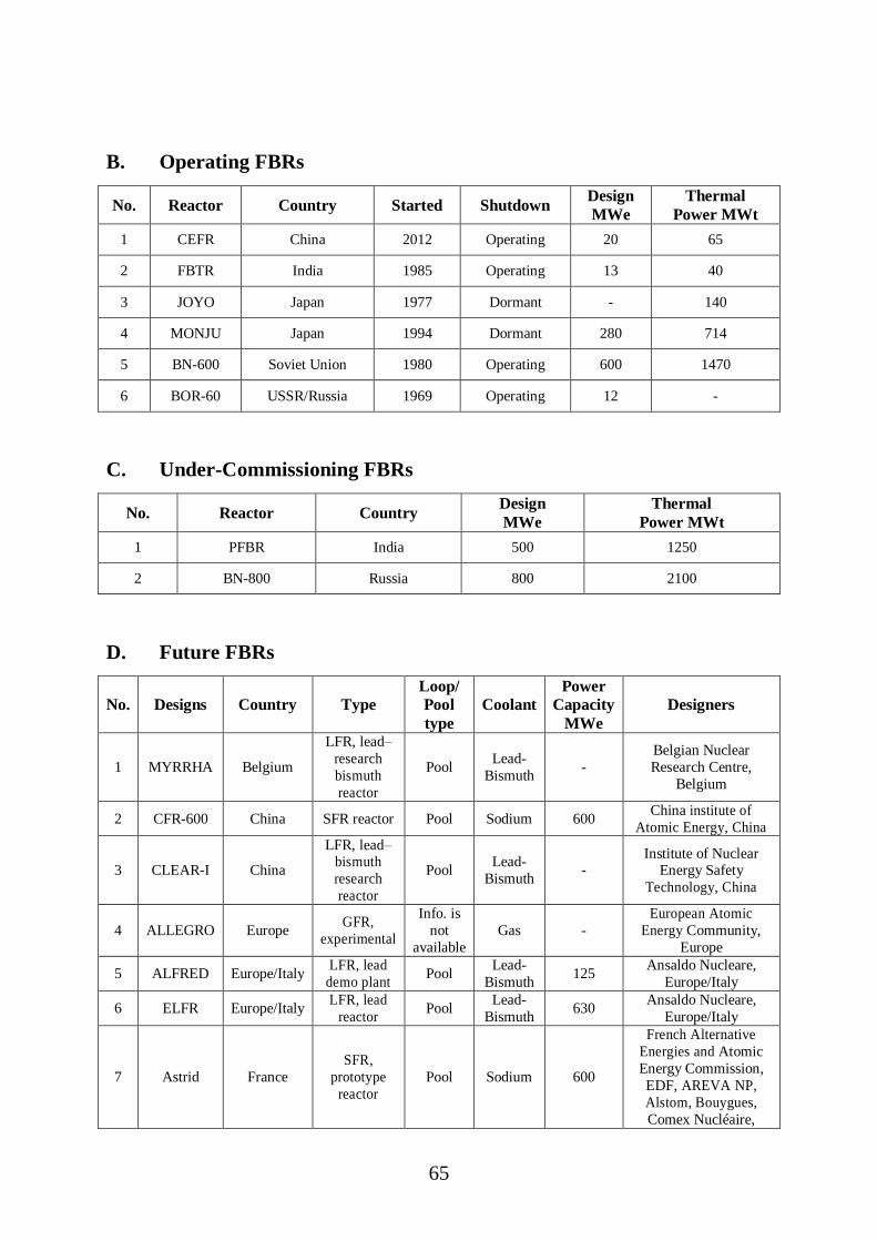
65
B. Operating FBRs
No. Reactor Country Started Shutdown Design
MWe
Thermal
Power MWt
1 CEFR China 2012 Operating 20 65
2 FBTR India 1985 Operating 13 40
3 JOYO Japan 1977 Dormant - 140
4 MONJU Japan 1994 Dormant 280 714
5 BN-600 Soviet Union 1980 Operating 600 1470
6 BOR-60 USSR/Russia 1969 Operating 12 -
C. Under-Commissioning FBRs
No. Reactor Country Design
MWe
Thermal
Power MWt
1 PFBR India 500 1250
2 BN-800 Russia 800 2100
D. Future FBRs
No. Designs Country Type
Loop/
Pool
type
Coolant
Power
Capacity
MWe
Designers
1 MYRRHA Belgium
LFR, lead–
research
bismuth
reactor
Pool Lead-
Bismuth -
Belgian Nuclear
Research Centre,
Belgium
2 CFR-600 China SFR reactor Pool Sodium 600 China institute of
Atomic Energy, China
3 CLEAR-I China
LFR, lead– bismuth
research
reactor
Pool Lead-
Bismuth -
Institute of Nuclear Energy Safety
Technology, China
4 ALLEGRO Europe GFR,
experimental
Info. is
not
available
Gas -
European Atomic
Energy Community,
Europe
5 ALFRED Europe/Italy LFR, lead
demo plant Pool
Lead-
Bismuth 125
Ansaldo Nucleare,
Europe/Italy
6 ELFR Europe/Italy LFR, lead
reactor Pool
Lead-
Bismuth 630
Ansaldo Nucleare,
Europe/Italy
7 Astrid France
SFR,
prototype
reactor
Pool Sodium 600
French Alternative
Energies and Atomic
Energy Commission,
EDF, AREVA NP,
Alstom, Bouygues,
Comex Nucléaire,

66
Toshiba, Jacobs, Rolls-
Royce and Astrium
Europe, France
8 MSFR France MSFR Loop Molten
Salt 1500
National Center for
Scientific Research,
France
9 FBR-1 & 2 India SFR, reactor Pool Sodium 500
Indira Gandhi Centre
for Atomic Research,
India
10 4S Japan SFR, small
reactor Pool Sodium 10 Toshiba, Japan
11 JSFR Japan SFR reactor Loop Sodium
750
(medium
scale),
1500
(large
scale)
Japan Atomic Energy
Agency, Japan
12 PGSFR Korea
SFR,
Prototype
reactor
Pool Sodium 150
Korea Atomic Energy
Research Institute, Rep.
of Korea
13 PEACER Korea
LFR, lead–
bismuth
demo plant
Pool Lead-
Bismuth 300
Seoul National
University, Rep. of
Korea
14 BN-1200 Russian
Federation SFR reactor Pool Sodium 1220
Experimental Design Bureau for Machine
Building, Russian
Federation
15 MBIR Russian
Federation
SFR,
research
reactor
Pool Sodium 100
Research and
Development Institute
of Power Engineering,
Russian Federation
16 BREST-
OD-300
Russian
Federation
LFR, pool
type lead
reactor
Pool Lead-
Bismuth 300
Research and
Development Institute
of Power Engineering,
Russian Federation
17 SVBR-100 Russian
Federation
LFR, small
modular
lead-
bismuth reactor
Pool Lead-
Bismuth 101
AKME Engineering,
Russian Federation
18 ELECTRA Sweden
LFR,
training lead
reactor
Info. is
not
available
Lead-
Bismuth -
Royal Institute of
Technology, Sweden
19 PRISM USA SFR, reactor Pool Sodium 311 GE-Hitachi, USA
20 TWR-P USA
SFR,
travelling
wave reactor
Pool Sodium 600 Terra Power, USA
21 G4M USA
LFR, small
modular
lead-
bismuth
reactor
Info. is
not
available
Lead-
Bismuth 25
Gen4 Energy Inc.,
USA
22 EM2 USA
GFR, high
temperature reactor
Info. is
not available
Gas 240 General Atomics, USA

67
APPENDIX-II
CATEGORIZATION OF REFERENCES
No. Category References [As per Section-7 of this report]
1 Under Sodium
Imaging Techniques
[1], [2], [3], [4], [5], [6], [7], [8], [9], [10], [11], [15], [16], [17], [29], [31], [40],
[42], [44], [45], [46], [47], [48], [49], [50], [51], [58], [59], [61], [68], [72], [82],
[124]
2 High Temperature
Transducers
[12], [13], [14], [18], [19], [20], [21], [26], [28], [30], [32], [41], [43],[53], [57],
[62], [63], [64], [66], [67], [76], [83], [93], [133], [134]
3 Radiation effect on
Transducers [14], [18], [20], [22], [23], [24], [27], [33], [65], [69], [70], [77], [128]
4 Waveguide based
imaging
[25], [34], [35], [36], [37], [38], [39], [52], [54], [55], [56], [60], [73], [74], [75],
[78], [79], [80], [81]
5 Ultrasonic Modeling [84], [85], [86], [87], [88], [89], [123], [125],[126],[127], [129]
6 Ultrasound
Beamforming
[97], [98], [99], [100], [101],[102],[103],[104],[105], [106], [107],
[108],[109],[110],[111],[112],[113],[114], [115], [116],[117],[118],[119], [120],
[121], [122]
7 Miscellaneous [71], [90],[91],[92], [94],[95],[96], [130],[131], [132]