Embed Size (px)
Citation preview

BARCBARC
Vienna, Austria, September 10-13, 2007
N.K. Maheshwari, P.K. Vijayan and D. Saha
Reactor Engineering Division, Bhabha Atomic Research Centre, Trombay, Mumbai, INDIA - 400 085
4th RCM on the IAEA CRP on Natural Circulation Phenomena, Modelling and Reliability of Passive Safety Systems
that Utilize Natural Circulation
Effect of non-condensable gases on condensation heat transfer

BARCBARC
Vienna, Austria, September 10-13, 2007
The problem is relevant to containment cooling using Passive Containment Cooling System (PCCS).
Containment of a nuclear reactor is a key component of the mitigation part of the defence in depth philosophy, since it is the last barrier designed to prevent large radioactive releases to the environment.
To provide safety-grade heat sink for preventing the containments exceeding its design pressure, passive systems for condensing steam are used in the nuclear reactors.
Effect of Non-condensable gases on condensation
The present talk deals with state of art on the effect of non-condensable gases on condensation heat transfer

BARCBARC
Vienna, Austria, September 10-13, 2007
The other important system encountering condensation in presence of noncondensable gas is the power plant condenser.
The presence of noncondensable gas greatly influences the condensation process warranting in-depth study of the phenomena.
Effect of Non-condensable gases on condensation

BARCBARC
Vienna, Austria, September 10-13, 2007
Effect of Non-condensable gases on condensation
• Condensation occurs when the temperature of vapor is reduced below its saturation temperature.
• Presence of even a small amount of Non-condensable gas (e.g. air, N2, H2, He, etc.) in the condensing vapor leads to a significant reduction in heat transfer during condensation.
• The buildup of non-condensable gases near the condensate film inhibits the diffusion of vapor from the bulk mixture to the liquid film.
Definition

BARCBARC
Vienna, Austria, September 10-13, 2007
Effect of Non-condensable gases on condensation
¡¡
Schematic representation of the effect of non-condensable gas on condensation

BARCBARC
Vienna, Austria, September 10-13, 2007
Effect of Non-condensable gases on condensation
The geometries of interest are tubes, plates, annulus, etc. and the flow orientation (horizontal, vertical) can be different for various applications.
The condensation heat transfer is affected by parameters such as
Mass fraction of non-condensable gas System pressure Gas/vapor mixture Reynolds number Orientations of surface Interfacial shear Prandtl number of condensate Multi-component non-condensable gases, etc.

BARCBARC
Vienna, Austria, September 10-13, 2007
Scenario
During a loss-of-coolant accident (LOCA) or a main-steam-line-break (MSLB) accident, or any other accident that causes a coolant release into the containment.
A large amount of steam is released into the containment which mixes with the noncondensable gases.
There are cooling surfaces provided for condensing the steam from steam/non-condensable gas mixture.
During condensation process, the steam condenses on the surfaces, while the non-condensable gases are accumulated on the film condensate layer creating an additional thermal resistance resulting in a degradation of the heat transfer to the wall.

BARCBARC
Vienna, Austria, September 10-13, 2007
Scenario
In the design and operation of a steam turbine the exit temperature of the process fluid is kept as low as possible so that a maximum change in enthalpy occurs during the conversion of heat into work. The presence of small proportion of air in the vapor can reduce heat transfer performance in a marked manner which increases the condenser pressure.

BARCBARC
Vienna, Austria, September 10-13, 2007
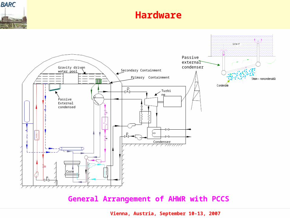
Hardware
PCCS with isolation Condenser
The system is adopted in ESBWR and SBWR

BARCBARC
Vienna, Austria, September 10-13, 2007
Hardware
PCCS with steel containment vessel
The Westinghouse AP-600, SPWR, EP-1000, JPSR
and AC-600 are the reactors utilizing this concept.

BARCBARC
Vienna, Austria, September 10-13, 2007
Hardware
PCCS with Building Condenser
SWR-1000: Containment Pressure Reduction and Heat Removal following a LOCA using Steam Condensation on Condenser Tubes.
BARCBARC
Vienna, Austria, September 10-13, 2007
Hardware
General Arrangement of AHWR with PCCS
FIG 1. SCHEM ATIC OF PASSIVE CONTAINM ENT COOLER
GDW P
Steam—noncondensable gas
Condensate
FIG 1. SCHEM ATIC OF PASSIVE CONTAINM ENT COOLER
GDW P
Steam—noncondensable gas
Condensate
Passive external condenser
Passive External condensed
Secondary Containment
Primary Containment
Core
Gravity driven water pool
Turbine
Condenser

BARCBARC
Vienna, Austria, September 10-13, 2007
Literature review
Test performed
Geometry and size
Working fluid Remarks
Othmer Copper tube
D= 76.2 mm, L=1.22 m
Air/steam Reduction in heat transfer coefficient (HTC) by 50% when 0.5% air is present in steam
Uchida Vertical tube
D=0.2 m, L=0.3 m
Air, Nitrogen and Argon with Steam
The correlation developed is widely used in nuclear reactor containment analysis
Al-Diwani and Rose
Cooled vertical copper plate, 97 x 97 mm
Air, Argon and Helium with
Experimental data show good agreement with the published data
Dehbi et al. Vertical copper tube
D=38 mm, L=3.5 m
Air/Steam
Air-Helium-Steam
Developed correlations for air/steam and air-Helium and steam mixture. Heat transfer coefficient estinated by heat and mass transfer model agree well with exptl. data
Liu et al. Vertical copper tube
D=40 mm, L=2 m
Air, Helium with Steam Developed a correlation and found that HTC is 2.2 times higher than HTC estimated by Uchida correlation
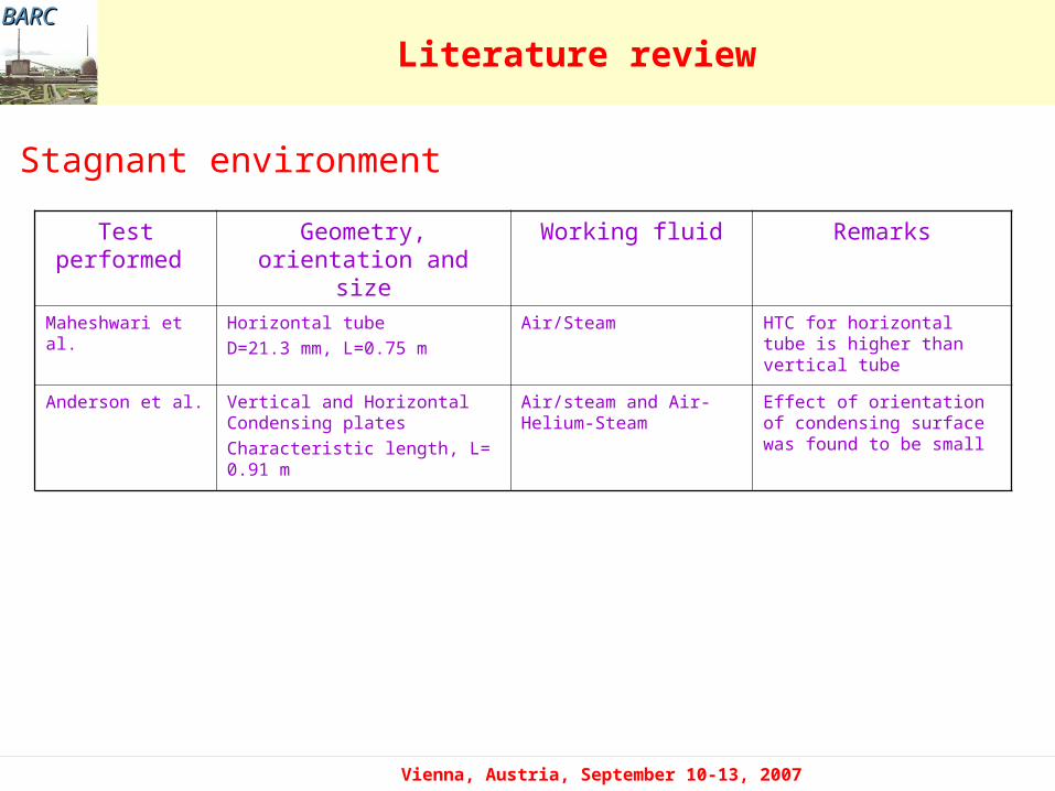
Stagnant environment
BARCBARC
Vienna, Austria, September 10-13, 2007
Literature review
Test performed Geometry, orientation and size
Working fluid Remarks
Maheshwari et al. Horizontal tube
D=21.3 mm, L=0.75 m
Air/Steam HTC for horizontal tube is higher than vertical tube
Anderson et al. Vertical and Horizontal Condensing plates
Characteristic length, L= 0.91 m
Air/steam and Air-Helium-Steam
Effect of orientation of condensing surface was found to be small
Stagnant environment

BARCBARC
Vienna, Austria, September 10-13, 2007
Literature review
Test performed
Geometry and size Working fluid
Remarks
Nagasaka et al. Vertical SS tube
(Full scale SBWR PCC tube)
Nitrogen/Steam
Helium/Steam
Facility is called GIRAFFE system. The results for average HTC were presented in terms of degradation coefficient (ratio of actual HTC and pure steam HTC by Nusselt theory)
Masoni et al. Vertical tube
(Full scale SBWR PCC tube)
Air/steam PANTHERS exptl. Facility. The results are given in terms of condenser efficiency as a function of inlet pressure and air mass fraction
Ogg Vertical SS tube
ID=49.0 mm, L=2.44 m
Air/Steam and
Helium/ Steam
A correlation for heat transfer coefficient was developed based on the experiment in term of Nusselt’s pure steam heat transfer coefficient and degradation factor consisting the two separate factors which involves mixture Reynolds number and air mass fraction.
Hassanein et al. Vertical SS tube
ID=46 mm, L=2.54 m
Air/Steam and Helium/Steam
The local Nusselt number was correlated as a function of local mixture Reynolds number, Jakob number and gas mass fraction and Schmidt number.
Vierow Vertical coper tube
ID=22.1 mm, L=2.13 m
Air/Steam The authors found that at an air inlet mass fraction of 14% the heat transfer coefficients were reduced to one-seventh the values of pure steam. Instabilities were observed at high air contents. Vierow developed a correlation for local heat transfer coefficient
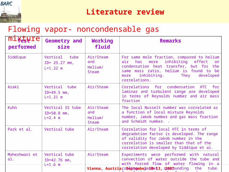
Flowing vapor-noncondensable gas mixture
BARCBARC
Vienna, Austria, September 10-13, 2007
Literature review
Test performed
Geometry and size
Working fluid
Remarks
Siddique Vertical tube
ID= 25.27 mm,
L=1.22 m
Air/Steam and
Helium/ Steam
For same mole fraction, compared to helium air has more inhibiting effect on condensation heat transfer, but for the same mass ratio, helium is found to be more inhibiting. They developed correlations.
Araki Vertical tube
ID=49.5 mm, L=1.21 m
Air/Steam Correlations for condensation HTC for laminar and turbulent range are developed in terms of Reynolds number and air mass fraction
Kuhn Vertical SS tube
ID=50.8 mm, L=2.4 m
Air/Steam and
Helium/ Steam
The local Nusselt number was correlated as a function of local mixture Reynolds number, Jakob number and gas mass fraction and Schmidt number. .
Park et al. Vertical tube Air/Steam Correlation for local HTC in terms of degradation factor is developed. The range of validity for Jakob number in the correlation is smaller than that of the correlation developed by Siddique et al.
Maheshwari et al. Vertical tube
ID=42.76 mm, L=1.6 m
Air/Steam Experiments were performed with natural convection of water outside the tube and with forced flow of water flowing in a cooling jacket surrounding the tube. Correlation is developed. A strong dependency of heat transfer coefficient on Reynolds number of the inlet mixture was also found
Flowing vapor- noncondensable gas mixture

BARCBARC
Vienna, Austria, September 10-13, 2007
Heat and mass transfer coefficient
A mass balance at the interface is done to yield the following equation
Heat and mass transfer
bnc,inc,
inc,//cond
WW
W
ρD
LmSh
fgH//
condm )
iT -
b(T
condh
1
gh
condh
1
fh
1 =
toth
hcond – Condensation heat transfer coefficient , hf – Film heat transfer coefficient
hg - Convective heat transfer coefficient
The heat transfer through the condensate film is balanced by the heat transfer through the gas/vapor interface which is sum of latent heat and sensible heat. This yields
Where, hcond is given by eq.,
where, L is the characteristic length which is outer diameter for horizontal tube and length of the tube for vertical tube

BARCBARC
Vienna, Austria, September 10-13, 2007
Condensate film model
The film heat transfer coefficient on vertical surface is calculated by Nusselt equation
4
1
wil
3
lfggll
f TTLμ
kHgρρρ0.943h
for Ref < 30
For condensation on horizontal tube the 0.943 is replaced by 0.725 in Nusselt equation
Condensate film heat transfer fg
H//cond
m ) i
T -b
(T cond
h
BARCBARC
Vienna, Austria, September 10-13, 2007
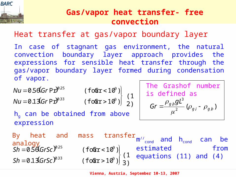
Heat transfer at gas/vapor boundary layer
In case of stagnant gas environment, the natural convection boundary layer approach provides the expressions for sensible heat transfer through the gas/vapor boundary layer formed during condensation of vapor.
)10Gr(for Pr13.0
)10Gr(for Pr56.0933.0
925.0
GrNu
GrNu
)10Gr(for 13.0
)10Gr(for 56.0933.0
925.0
GrScSh
GrScSh
)( ,,2
3,
bgigbg gLGr
The Grashof number is defined as
By heat and mass transfer analogy
Gas/vapor heat transfer- free convection
hg can be obtained from above expression
(12)
(13)
m//cond and hcond can be estimated
from equations (11) and (4)

BARCBARC
Vienna, Austria, September 10-13, 2007
Heat transfer at gas/vapor boundary layer
In case of vapor/gas mixture flowing inside a vertical tube, the forced convective boundary layer approach provides the expressions for sensible heat transfer through the gas/vapor boundary layer formed during condensation of vapor. The following Gnielinski correlation is used
Gas/vapor heat transfer- Forced convection
1)-2/3(Pr1/2/2)s
12.7(f +1
1000)Pr-/2)(Res
(fNu
By heat and mass transfer analogy
1)-2/3(Sc1/2/2)s
12.7(f +1
1000)Pr-/2)(Res
(fSh
Re is local mixture Reynolds number in the bulk fluid, and fs is the friction factor for smooth tube
When the Reynolds number is less than 2300, a fully developed laminar flow regime is assumed. A value of 3.66 is assigned for Nu and Sh
2300< Re < 5 x 10⁶

BARCBARC
Vienna, Austria, September 10-13, 2007
Heat transfer enhancement
Following modifications are carried out to account for the
• Film Waviness/ripple effect on condensate film heat transfer coefficient
• Condensate film roughness effect on condensation and convective heat transfer
• Suction effect
• Developing flow effect on heat and mass transfer

BARCBARC
Vienna, Austria, September 10-13, 2007
Some of the correlations available in literature
Number of correlations are available in the literature. Some of the
correlations developed are given below.
7.0
)( 1380
nc
ncUchidatot W
Wh
The correlation developed by Uchida
Correlations
nc
nctot W
Wh
12844.11
The Tagami correlation
Condensation in stagnant atmosphere

BARCBARC
Vienna, Austria, September 10-13, 2007
0.3070.252tot
2.344stot dTPCXh
The correlation developed by Liu et al.
2.533 x 10⁵ Pa < Ptot < 4.559 x 10⁵ Pa4 oC < dT < 25 oC; 0.395 < Xs < 0.873
Dehbi correlation
0.25
wb
ncttot0.05
tot(Dehbi)TT
logW458.3P243828.7P3.7Lh
for 0.3 m < L < 3.5 m; 1.5 atm. < Pt < 4.5 atm.;10 oC < (Tb-Tw) < 50 oC
Where, C=55.635 W/m2 Pa0.252 oC1.307
Correlations

BARCBARC
Vienna, Austria, September 10-13, 2007
Correlations
Condensation inside the vertical tube
There are two types of correlations for estimating the heat transfer coefficient.
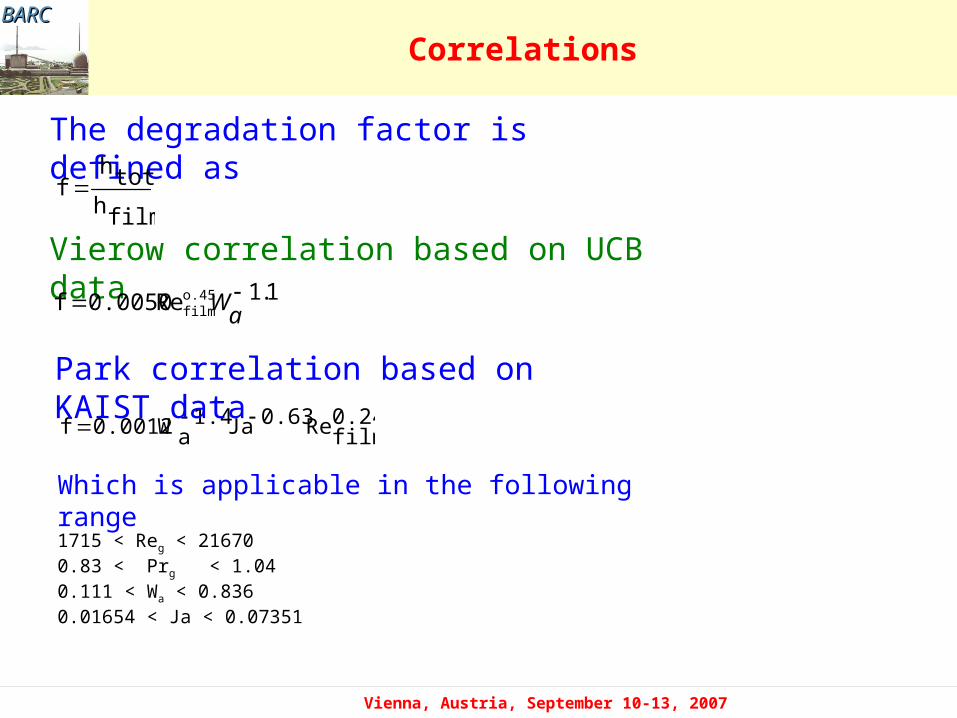
The local heat transfer coefficient is expressed in the form of a degradation factor defined as the ratio of the experimental heat transfer coefficient (when noncondensable gas is present) and pure steam heat transfer coefficient.
The degradation factor is a function of local noncondensable gas mass fraction and mixture Reynolds number (or condensate Reynolds number).
BARCBARC
Vienna, Austria, September 10-13, 2007
Correlations
The local heat transfer coefficient is expressed in the form of dimensionless numbers and does not require information of condensation heat transfer coefficient for pure steam.
In these correlations, local Nusselt number is expressed as a function of mixture Reynolds number, Jacob number, noncondensable gas mass fraction and condensate Reynolds number, etc.
BARCBARC
Vienna, Austria, September 10-13, 2007
Correlations
Vierow correlation based on UCB data1.1Re0.0050f o.45
filma
W
0.24filmRe0.63Ja1.4
aW0.0012f
Park correlation based on KAIST data
1715 < Reg < 216700.83 < Prg < 1.040.111 < Wa < 0.8360.01654 < Ja < 0.07351
Which is applicable in the following range
The degradation factor is defined as
filmhtoth
f

BARCBARC
Vienna, Austria, September 10-13, 2007
Correlations
Correlation based on non-dimensional numbers
Siddique Correlation based on MIT data
0.741Ja1.105aW1.137ReNu(x) 0.404
g
Which applies in the following range of experiments
0.1 < Wa < 0.95 ; 445 < Reg < 22700 ; 0.004 < Ja < 0.07
Maheshwari correlation based on BARC experiments
5.08.085.015.0 ReRe15.0)( gafilm JaWxNu
This equation is valid in the following range
0.1 < Wa < 0.68000 < Reg < 227000.005 < Ja < 0.07

BARCBARC
Vienna, Austria, September 10-13, 2007
Condensation inside a vertical tube
Work done in BARC on condensation inside vertical tube
• Experimental studies on condensation in presence of air in vertical tube
• Development of a theoretical model to investigate condensation in presence of noncondensable gas when steam/air mixture is flowing down inside the tube
• Studies on the effects of various parameters on condensation in presence of noncondensable gas
• Comparison of theoretical results with BARC experimental data and data available in literature
BARCBARC
Vienna, Austria, September 10-13, 2007
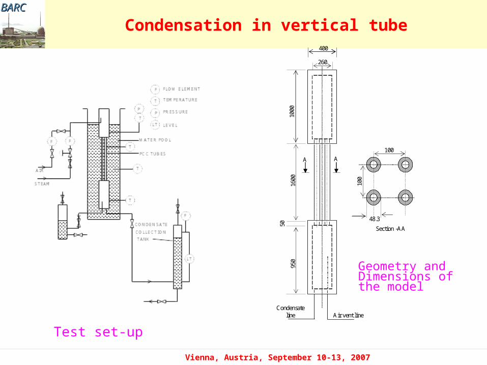
Condensation in vertical tube400
260
100
100
48.3
1000
1600
950
50
Air vent lineCondensate
line
A A
Section -AA
Geometry and Dimensions of the model
Test set-up

BARCBARC
Vienna, Austria, September 10-13, 2007
Forced flow condensation
Variation of total heat transfer coefficient along the length of the tube
BARCBARC
Vienna, Austria, September 10-13, 2007
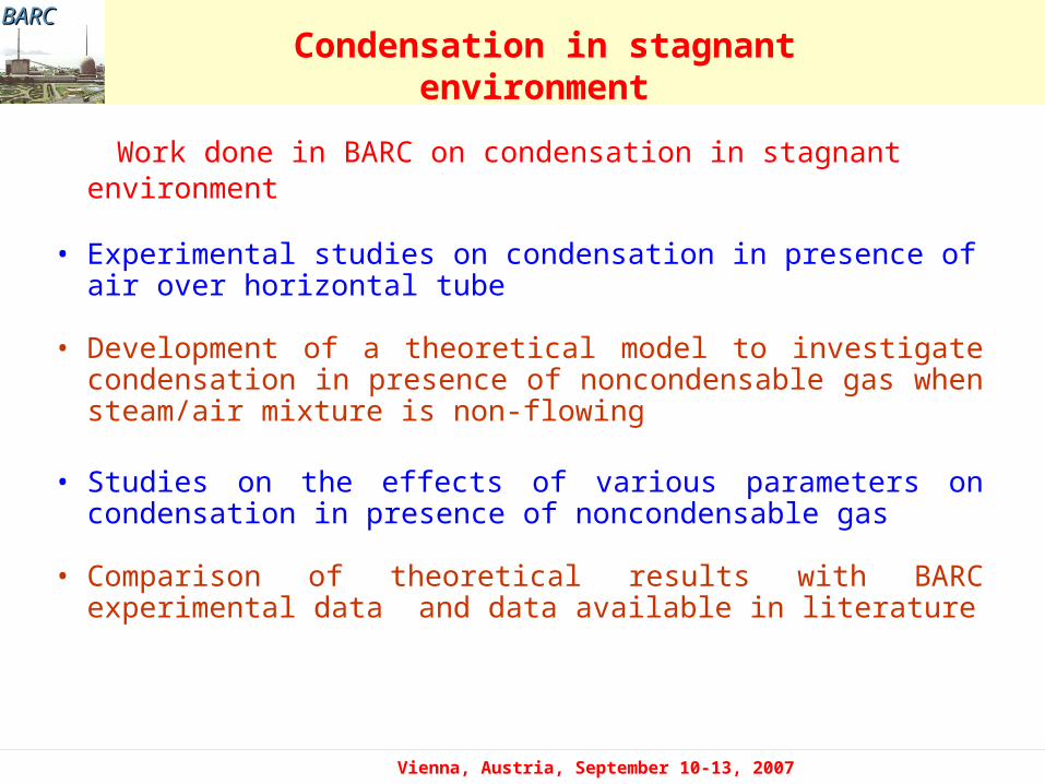
Work done in BARC on condensation in stagnant environment • Experimental studies on condensation in presence of air over
horizontal tube
• Development of a theoretical model to investigate condensation in presence of noncondensable gas when steam/air mixture is non-flowing
• Studies on the effects of various parameters on condensation in presence of noncondensable gas
• Comparison of theoretical results with BARC experimental data and data available in literature
Condensation in stagnant environment

BARCBARC
Vienna, Austria, September 10-13, 2007
Schematic of the steam condensation experimental set up
Pressure regulator
Compressed air
condensing Section21.3 mm OD tube
Insulated lines
20001000
750
To drain
Water inlet
Heater0-18 kW
Water
LT
P
P
T T
T
P
ThermocouplePressure transmitterLevel transmitterLT
Relief valve and rupture dick
Noz
zles
for
ve
rtic
al
inst
alla
tion
of
mod
elRot
amet
er (
0-8
lpm
)
Experiment set up

BARCBARC
Vienna, Austria, September 10-13, 2007
Variation of heat transfer coefficient with air mass fraction
Comparison between
experimental and theoretical results

BARCBARC
Vienna, Austria, September 10-13, 2007
Free and forced convective Condensation
Comparison of free and forced convective heat transfer coefficients

BARCBARC
Vienna, Austria, September 10-13, 2007
Summary
Work done by various researchers is reviewed
The report deals with the following
- Condensation in stagnant steam/non-condensable environment - Condensation in a flowing steam/non-condensable mixture - Geometry considered -tubes with different orientations, plate, etc.
Recent work performed in BARC is also presented