Embed Size (px)
Citation preview

Bar code
75M7000UWD
EnglishES-A161215-1
QUICK SETUP GUIDEBefore using the TV, please read this guide thoroughly
and retain it for future reference. For more detailed instructions, please see the User Manual.
1
Contents
Contents
Accessories List..............................................................................................................1Wall Brackets Installing Instructions ...............................................................................2TV Front..........................................................................................................................5TV Rear ..........................................................................................................................6Making Connections .......................................................................................................7Remote Control ............................................................................................................12Turning the TV on for the First Time .............................................................................14Specifications ...............................................................................................................15
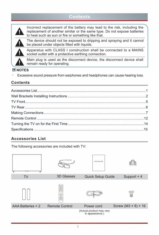
TV 3D Glasses Quick Setup Guide
AAA Batteries × 2 Remote Control Power cord
Support × 4
Screw (M3 × 8) × 16
Accessories List
The following accessories are included with TV:
Quick Setup Guide
Incorrect replacement of the battery may lead to the risk, including the replacement of another similar or the same type. Do not expose batteries to heat such as sun or fire or something like that.The device should not be exposed to dripping and spraying and it cannot be placed under objects filled with liquids.Apparatus with CLASS I construction shall be connected to a MAINS socket outlet with a protective earthing connection.Main plug is used as the disconnect device, the disconnect device shall remain ready for operating.
NOTESExcessive sound pressure from earphones and headphones can cause hearing loss.
OK
VOLC
BACK EXIT
INPUT
SubtitleT.shift
EPGCH.List
CH
APP
Info
APP
(Actual product may vary in appearance.)
2
CAUTION
Be sure to disconnect the A/C power cord before removing a base stand or installing Wall-Mount brackets.The LED display is very fragile, and must be protected at all times when installing the base stand. Be sure that no hard or sharp object, or anything that could scratch or damage the LED display, comes into contact with it. DO NOT exert pressure on the front of the TV at any time because the screen could crack.
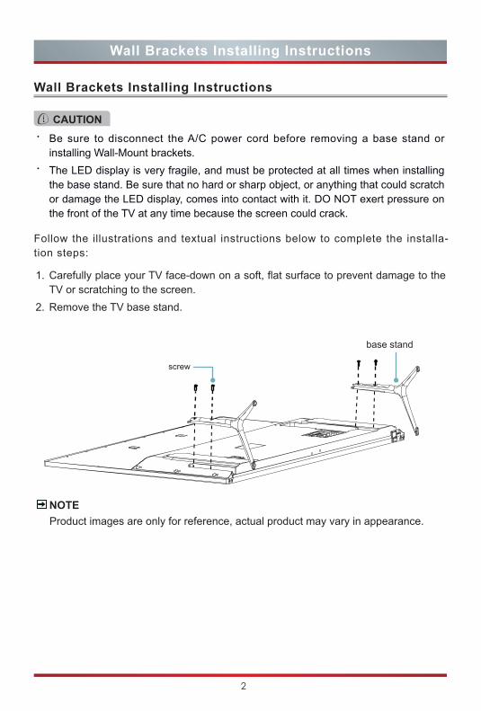
Follow the illustrations and textual instructions below to complete the installa-tion steps:
Product images are only for reference, actual product may vary in appearance. NOTE
1. Carefully place your TV face-down on a soft, flat surface to prevent damage to theTV or scratching to the screen.
2. Remove the TV base stand.
base stand
screw
Wall Brackets Installing Instructions
Wall Brackets Installing Instructions
3
Wall Brackets Installing Instructions
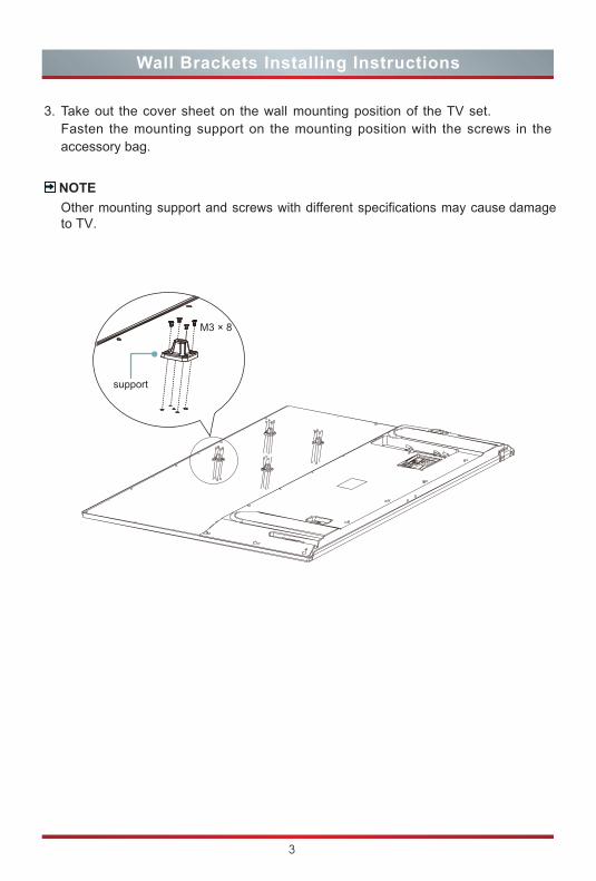
3. Take out the cover sheet on the wall mounting position of the TV set. Fasten the mounting support on the mounting position with the screws in the accessory bag.
NOTEOther mounting support and screws with different specifications may cause damageto TV.
M3 × 8
support
4
Wall Brackets Installing Instructions
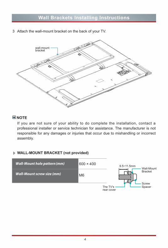
3 Attach the wall-mount bracket on the back of your TV.
NOTEIf you are not sure of your ability to do complete the installation, contact a professional installer or service technician for assistance. The manufacturer is not responsible for any damages or injuries that occur due to mishandling or incorrect assembly.
wall-mount bracket
WALL-MOUNT BRACKET (not provided)
6 4
M6
9.5~11.5mm
5
TV Front
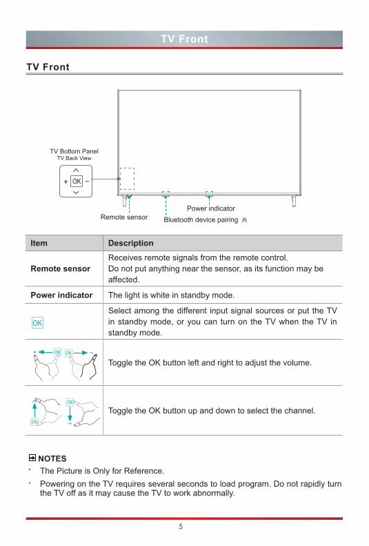
TV Front
NOTESThe Picture is Only for Reference. Powering on the TV requires several seconds to load program. Do not rapidly turn the TV off as it may cause the TV to work abnormally.
Item Description
Remote sensorReceives remote signals from the remote control. Do not put anything near the sensor, as its function may be affected.
Power indicator The light is white in standby mode.
Select among the different input signal sources or put the TV in standby mode, or you can turn on the TV when the TV in standby mode.
Toggle the OK button left and right to adjust the volume.
Toggle the OK button up and down to select the channel.
OK
TV Bottom PanelTV Back View
Remote sensor Power indicator
Bluetooth device pairing
6
TV Rear
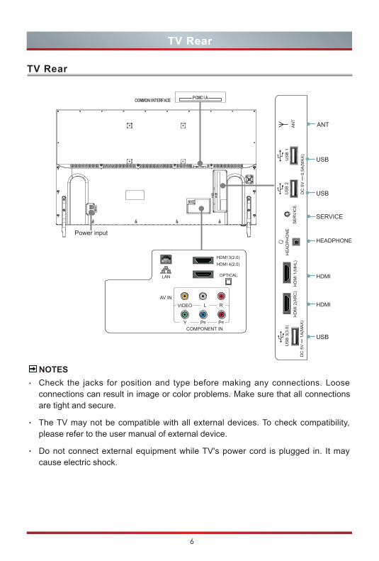
TV Rear
ANT AN
T
HEADPHONE
HDMI
HDMI
SERVICE
HD
MI 1
(MH
L)H
DM
I 2(A
RC
)S
ER
VIC
E
HE
AD
PH
ON
E
USB
USB
USB
US
B 3
(3.0
)
DC
5V
--- 1
A(M
AX
)D
C 5
V
0.5
A(M
AX
)
US
B 1
US
B 2
LAN
HDMI 3(2.0)HDMI 4(2.0)
OPTICAL
Y
VIDEO
PB
L
PR
RAV IN
COMPONENT IN
Power input
COMMONINTERFACEPCMCIA
NOTESCheck the jacks for position and type before making any connections. Loose connections can result in image or color problems. Make sure that all connections are tight and secure.
The TV may not be compatible with all external devices. To check compatibility, please refer to the user manual of external device.
Do not connect external equipment while TV's power cord is plugged in. It may cause electric shock.
7
Making Connections
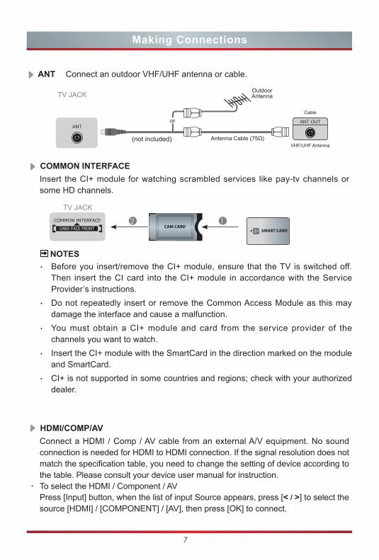
HDMI/COMP/AVConnect a HDMI / Comp / AV cable from an external A/V equipment. No sound connection is needed for HDMI to HDMI connection. If the signal resolution does not match the specification table, you need to change the setting of device according to the table. Please consult your device user manual for instruction.
· To select the HDMI / Component / AVPress [Input] button, when the list of input Source appears, press [< / >] to select the source [HDMI] / [COMPONENT] / [AV], then press [OK] to connect.
TV JACKOutdoorAntenna
Antenna Cable (75Ω)
or ANT OUT
Cable
VHF/UHF Antenna
ANT Connect an outdoor VHF/UHF antenna or cable.
ANT
(not included)
COMMON INTERFACE Insert the CI+ module for watching scrambled services like pay-tv channels or some HD channels.
SMART CARDCAM CARD
TV JACK
1 2
NOTESBefore you insert/remove the CI+ module, ensure that the TV is switched off. Then insert the CI card into the CI+ module in accordance with the Service Provider’s instructions.Do not repeatedly insert or remove the Common Access Module as this may damage the interface and cause a malfunction.You must obtain a CI+ module and card from the service provider of the channels you want to watch.Insert the CI+ module with the SmartCard in the direction marked on the module and SmartCard.CI+ is not supported in some countries and regions; check with your authorized dealer.
8
Making Connections
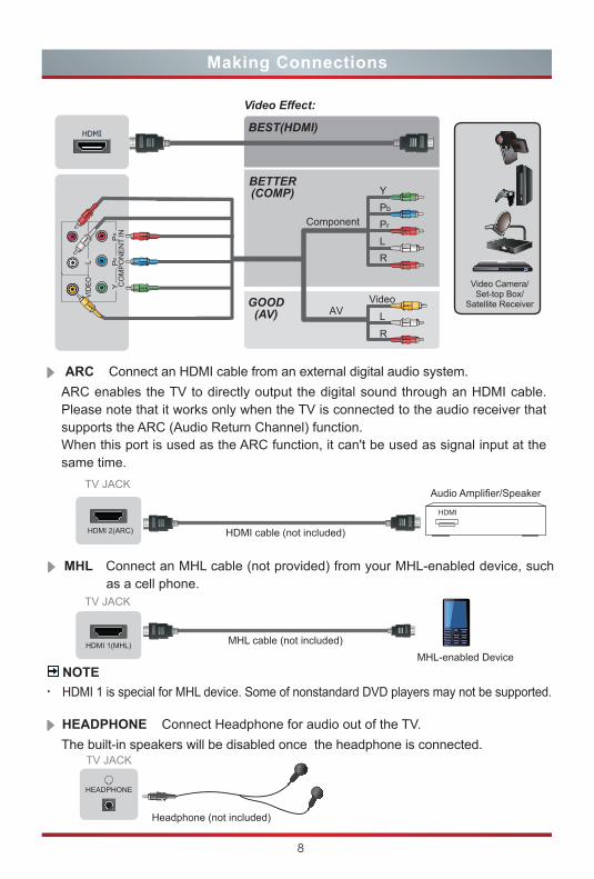
ARC Connect an HDMI cable from an external digital audio system. ARC enables the TV to directly output the digital sound through an HDMI cable. Please note that it works only when the TV is connected to the audio receiver that supports the ARC (Audio Return Channel) function.When this port is used as the ARC function, it can't be used as signal input at the same time.
TV JACK
TV JACK
HDMI cable (not included)
MHL cable (not included)
HDMI 2(ARC)
HDMI
Audio Amplifier/Speaker
HDMI 1(MHL)
MHL-enabled Device
MHL Connect an MHL cable (not provided) from your MHL-enabled device, such as a cell phone.
BEST(HDMI)
Video Effect:
BETTER(COMP)
GOOD(AV)
Video Camera/Set-top Box/
Satellite ReceiverAV
YPb
PrComponent
LR
Video
L
R
VIDE
OL
R PR
PB
Y CO
MP
ON
EN
T IN
HEADPHONE Connect Headphone for audio out of the TV. The built-in speakers will be disabled once the headphone is connected.
TV JACK
Headphone (not included)
HEADPHONE
NOTEHDMI 1 is special for MHL device. Some of nonstandard DVD players may not be supported.
9
Making Connections
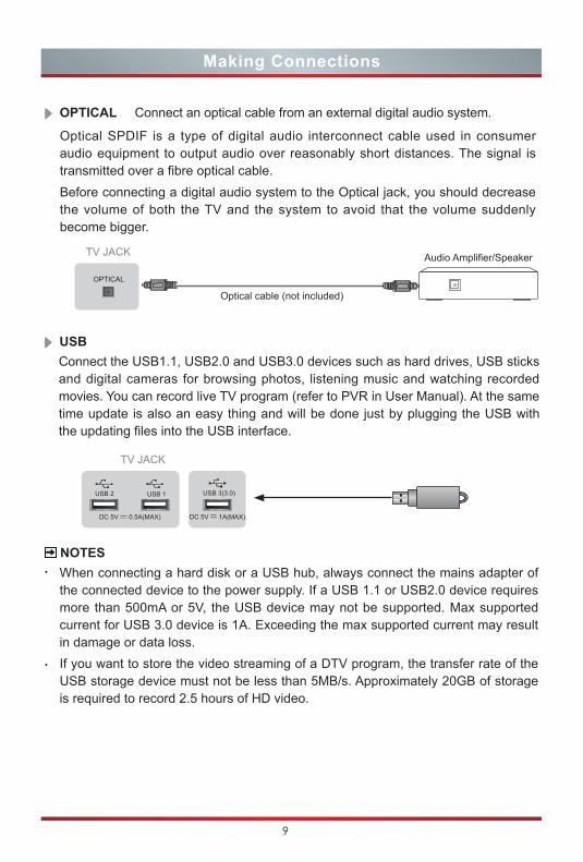
USB Connect the USB1.1, USB2.0 and USB3.0 devices such as hard drives, USB sticks and digital cameras for browsing photos, listening music and watching recorded movies. You can record live TV program (refer to PVR in User Manual). At the same time update is also an easy thing and will be done just by plugging the USB with the updating files into the USB interface.
NOTESWhen connecting a hard disk or a USB hub, always connect the mains adapter of the connected device to the power supply. If a USB 1.1 or USB2.0 device requires more than 500mA or 5V, the USB device may not be supported. Max supported current for USB 3.0 device is 1A. Exceeding the max supported current may result in damage or data loss. If you want to store the video streaming of a DTV program, the transfer rate of the USB storage device must not be less than 5MB/s. Approximately 20GB of storage is required to record 2.5 hours of HD video.
OPTICAL Connect an optical cable from an external digital audio system.
Optical SPDIF is a type of digital audio interconnect cable used in consumer audio equipment to output audio over reasonably short distances. The signal is transmitted over a fibre optical cable. Before connecting a digital audio system to the Optical jack, you should decrease the volume of both the TV and the system to avoid that the volume suddenly become bigger.
TV JACK
Optical cable (not included)
Audio Amplifier/Speaker
OPTICAL
TV JACK
DC 5V 0.5A(MAX)
USB 1USB 2 USB 3(3.0)
DC 5V --- 1A(MAX)
10
Making Connections
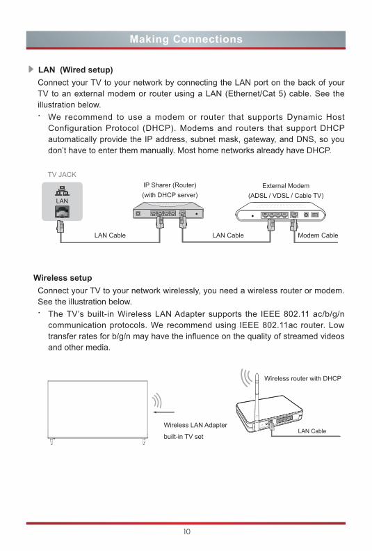
LAN (Wired setup) Connect your TV to your network by connecting the LAN port on the back of your TV to an external modem or router using a LAN (Ethernet/Cat 5) cable. See the illustration below.· We recommend to use a modem or router that supports Dynamic Host
Configuration Protocol (DHCP). Modems and routers that support DHCP automatically provide the IP address, subnet mask, gateway, and DNS, so you don’t have to enter them manually. Most home networks already have DHCP.
Wireless setup Connect your TV to your network wirelessly, you need a wireless router or modem. See the illustration below. · The TV’s built-in Wireless LAN Adapter supports the IEEE 802.11 ac/b/g/n
communication protocols. We recommend using IEEE 802.11ac router. Low transfer rates for b/g/n may have the influence on the quality of streamed videos and other media.
Wireless router with DHCP
LAN CableWireless LAN Adapter
built-in TV set
TV JACK
Modem CableLAN CableLAN Cable
External Modem(ADSL / VDSL / Cable TV)
IP Sharer (Router)(with DHCP server)
LAN
11
Making Connections
NOTESYou must use the built-in Wireless LAN Adapter to use a wireless network because the set doesn’t support external USB network adapter.If the wireless router supports DHCP, your TV can connect more easily to the wireless network.If you apply a security system other than the systems listed below, it will not work with the TV.Security system : WPA, WEP, WPA2. In order to guarantee smooth network, the distance between router and TV is less than 10 meters.
What is FreeviewPlus?FreeviewPlus is a new television service delivered via broadband providing a state of the art Electronic Program Guide (EPG) and seamless access to catch-up TV across the free-to-air networks with the simple press of a button.
How does it work?First ensure the TV is connected to internet and an antenna system. Then when you’re watching TV, you’ll briefly see a prompt at the top left of the screen. Press the ‘Green’ button on your remote to launch FreeviewPlus. More information about FreeviewPlus can be found on http://www.freeview.com.au/
NOTEFreeviewPlus service only available in Australia territories.
12
Remote Control
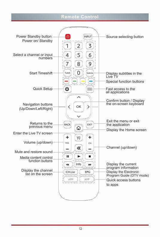
Mute and restore sound
Display the Electronic Program Guide (DTV mode)
Display the channel list on the screen
Display the current program information
Exit the menu or exit the application
Channel (up/down)
Returns to the previous menu
Power Standby button: Power on/ Standby
Volume (up/down)
Navigation buttons(Up/Down/Left/Right)
Select a channel or input numbers
Start Timeshift Display subtitles in the Live TV
Quick Setup
Confirm button / Display the on-screen keyboard
Fast access to the all applications
Source selecting button
Special function buttons
OK
BACK EXIT
INPUT
SubtitleT.shift
EPGCH.List
CH
Media content control function buttons
Enter the Live TV screenDisplay the Home screen
Quick access buttons to apps
APP
Info
VOL
APP
13
Remote Control Operation Range
1. Point the remote control at theTV within no more than 5 metresfrom the remote control sensoron the TV and within 60° in frontof the TV.
2. The operating distance may varydepending on the brightness ofthe room.
Remote Control
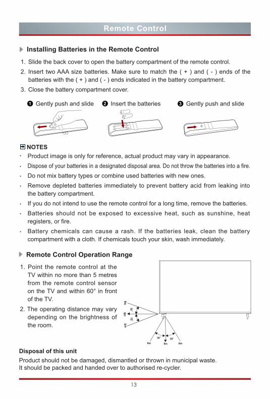
Installing Batteries in the Remote Control
NOTESProduct image is only for reference, actual product may vary in appearance.Dispose of your batteries in a designated disposal area. Do not throw the batteries into a fire.Do not mix battery types or combine used batteries with new ones.Remove depleted batteries immediately to prevent battery acid from leaking into the battery compartment.If you do not intend to use the remote control for a long time, remove the batteries.Batteries should not be exposed to excessive heat, such as sunshine, heat registers, or fire.Battery chemicals can cause a rash. If the batteries leak, clean the battery compartment with a cloth. If chemicals touch your skin, wash immediately.
1. Slide the back cover to open the battery compartment of the remote control.2. Insert two AAA size batteries. Make sure to match the ( + ) and ( - ) ends of the
batteries with the ( + ) and ( - ) ends indicated in the battery compartment.3. Close the battery compartment cover.
1 Gently push and slide 3 Gently push and slide2 Insert the batteries
Disposal of this unitProduct should not be damaged, dismantled or thrown in municipal waste.It should be packed and handed over to authorised re-cycler.
14
Turning the TV on for the First Time
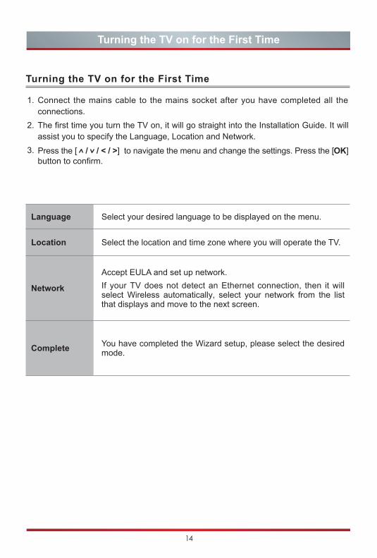
Turning the TV on for the First Time
1. Connect the mains cable to the mains socket after you have completed all theconnections.
2. The first time you turn the TV on, it will go straight into the Installation Guide. It willassist you to specify the Language, Location and Network.
3. Press the [ / / < / >] to navigate the menu and change the settings. Press the [OK]button to confirm.
Language Select your desired language to be displayed on the menu.
Location Select the location and time zone where you will operate the TV.
Network
Accept EULA and set up network.If your TV does not detect an Ethernet connection, then it will select Wireless automatically, select your network from the list that displays and move to the next screen.
Complete You have completed the Wizard setup, please select the desired mode.
15
Specifications
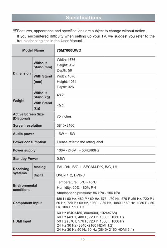
Features, appearance and specifications are subject to change without notice.If you encountered difficulty when setting up your TV, we suggest you refer to the troubleshooting tips in the User Manual.
Model Name 75M7000UWD
Dimension
Without Stand(mm)
Width: 1676 Height: 962 Depth: 56
With Stand(mm)
Width: 1676 Height: 1034 Depth: 326
Weight
Without Stand(kg) 48.2
With Stand(kg)
49.2
Active Screen Size (Diagonal) 75 inches
Screen resolution 3840×2160
Audio power 15W + 15W
Power consumption Please refer to the rating label.
Power supply 100V - 240V 50Hz/60Hz
Standby Power 0.5W
Receiving systems
Analog PAL-D/K, B/G, I SECAM-D/K, B/G, L/L’
Digital DVB-T/T2, DVB-C
Environmental conditions
Temperature: 5°C - 45°C Humidity: 20% - 80% RH Atmospheric pressure: 86 kPa - 106 kPa
Component Input / P 027 ,zH 05/ P 675 ,zH 05/ I 675 ,zH 06 / P 084 ,zH 06 / I 084
50 Hz, 720 P / 60 Hz, 1080 I / 50 Hz, 1080 I / 60 Hz, 1080 P / 50 Hz, 1080 P / 60 Hz
HDMI Input
60 Hz (640×480, 800×600, 1024×768)60 Hz (480 I, 480 P, 720 P, 1080 I, 1080 P)50 Hz (576 I, 576 P, 720 P, 1080 I, 1080 P)24 Hz 30 Hz (3840×2160 HDMI 1,2)24 Hz 30 Hz 50 Hz 60 Hz (3840×2160 HDMI 3,4)