Embed Size (px)
Citation preview

Lewis & Clark Water Supply Project Final Engineering Report
Banner/HDR/TRC Mariah 5-20
5.3. Water Treatment Facilities
5.3.1. General
The Water Treatment alternatives were evaluated in Section 4 and the recommended process is conventional treatment (lime softening) with filtration. Section 4 evaluated conventional technology versus membrane technology, disinfection alternatives and presented the cost analysis for the treatment alternatives. This section will present additional detail for the basis of design to be used for the preliminary layout of the various process components.
5.3.2. Softening Basins
5.3.2.1. Operating Modes
The alternative evaluation identified softening, filtration and disinfection as the recommended processes to meet the finished water quality goals for the project. The basin may be preceded by pretreatment basins (PAC contactors for organics reduction or SOC adsorption/atrazine removal) in the future and the plant hydraulic profile will accommodate these units. The operational scheme for the softening units could include the following:
? Full softening mode to provide maximum capacity and hardness reduction.
? Split treatment softening mode to treat a variable amount (up to 50% of flow) in a full
softening mode, then blending the water with the bypass flow. This mode could reduce chemical and sludge handling cost. To accomplish the treatment scheme, the softening/blending basins would have approximately a 2-foot difference in elevation between each basin.
5.3.2.2. Water Quality
The water quality conditions and summary of the criteria for the softening basins were discussed in Sections 3 and 4. Table 5.3-1 summarizes the projected influent and effluent water quality characteristics for the softening basins. The secondary maximum contaminant levels (SMCL’s) as applicable for each parameter are also listed. SMCL’s are intended for the control of aesthetic factors and are therefore considered guidelines rather than regulations.

Lewis & Clark Water Supply Project Final Engineering Report
Banner/HDR/TRC Mariah 5-21
Table 5.3-1 Estimated Water Quality
Parameter Influent Quality Effluent Quality SMCL
Total Hardness (mg/l as CaCO3) 250 – 260 125 – 175 N/A
Iron (mg/l) 0.5 – 2.0 <0.01 0.3
Manganese (mg/l) 0.1 – 0.3 <0.01 0.05
Total Alkalinity (mg/l as CaCO3) 175 – 185 50 – 100 N/A
TOC (mg/l) 2 – 3 1 – 2.5 N/A
Color (Units) 1 – 10 - 15
Turbidity (NTU) - 1 – 3 N/A
pH (Units) 7.5 – 8.5 8.3 – 9.5 7.5 – 8.5
The softening basin will remove the iron and manganese as well as a portion of the hardness, depending upon the amount of softening provided. A reduction in the alkalinity occurs in the softening process and the effluent pH will be impacted by full versus split treatment softening. Some reduction of TOC will occur, however, the influent levels are anticipated to be very low, therefore significant reductions are not probable. The goal will be to maintain turbidity levels in the effluent to less than 5 NTU to optimize filter run time.
5.3.2.3. Basin Types
The options available for the softening basin types to be used include two categories; conventional flocculation/clarification units and solids contact flocculation/clarification units. There are two common types of systems used in each category.
Conventional Flocculation/Clarification
? Separated flocculation and sedimentation basins ? Combined flocculation and sedimentation basins
Solids Contact Flocculation/Clarification
? Sludge Blanket Type ? Slurry Recirculation Type

Lewis & Clark Water Supply Project Final Engineering Report
Banner/HDR/TRC Mariah 5-22
The conventional flocculation/clarification treatment units consist of a separate rapid mix zone, flocculation zone and sedimentation zone. As previously discussed in Section 4.4, the separated systems are more costly than the unit which combine these functions. Therefore, the alternatives will include only basins which combine the flocculation/sedimentation functions.
Conventional Flocculation/Sedimentation
If flocculation and sedimentation is combined in one basin, the flocculation zone is normally located in the center of the basin, separated from the sedimentation zone by a baffle wall. The flocculation zone usually employs a turbine type flocculator in the vertical position. The flocculated particles flow from the flocculation zone into the sedimentation zone and are removed by a circular scraper. An example of a basin in this configuration is shown in Figure No. 5.3.1, entitled “Conventional Flocculation/Sedimentation in Circular Basin”. The basins can be square or circular, depending on plant layout requirements. Conventional flocculation/clarification units are used most often with surface waters, because the contaminants which normally exist in the surface waters easily form a nucleus for flocculation particles. The absence of internal sludge recirculation (which is used in solids contact basins) also minimizes the potential for contaminant concentrating.
Solids Contact Flocculation/Sedimentation
A solids-contact flocculation/sedimentation unit combines the processes of coagulation, flocculation, sedimentation, and sludge removal in a single treatment basin. Settled sludges may be recirculated either internally or externally. The solids contact units utilize sludge recirculation and suspension of precipitated solids to effect efficient water treatment in less space and in a shorter time than conventional treatment. The success of this approach is based on incoming raw water being brought into intimate contact and recirculated with waters carrying previously formed precipitates. The presence of these previously formed precipitates accelerates the chemical reactions. Solids contact basins are well suited for the precipitation of hardness from well waters of consistent quality. The presence of previously precipitated solids provides nuclei for the development of additional precipitates of calcium carbonate and magnesium hydroxide. The improvement of softening by maintaining a slurry of precipitated material has been well demonstrated over the years. Many types of solids contact basins are available. Each of the several manufacturers claims advantages over the designs of other manufacturers. The several designs, however, may be classified into two general types:


Lewis & Clark Water Supply Project Final Engineering Report
Banner/HDR/TRC Mariah 5-24
1. Sludge blanket type, wherein the raw water is mixed with lime or other reagents and
then rises through a “sludge blanket” of previously precipitated material.
2. Slurry recirculation type, wherein the raw water and reagents are added to a relatively large recirculating slurry of precipitated material.
Both types of solids contact basins have been used successfully on softening. Figures 5.3-2, entitled “Solids Contact Clarifier – Sludge Blanket Type”, and 5.3-3, entitled “Solids Contact Clarifier – Sludge Recirculation Type”, illustrate each type.
An alternative solids contact unit which has also been used for water treatment is called a Pulsator. This unit is designed to distribute the influent flow evenly across the bottom of the unit through a series of distribution pipes. The influent flow then is pulsed through the sludge blanket alternately expanding and contracting the sludge bed. This causes the sludge blanket to remain uniform across the basin and when expanded allows excess sludge to be removed through a sludge concentrator. This type of unit is well suited for low turbidity waters which do not require softening. With softening, the units are prone to be maintenance problems due to the precipitation of calcium carbonate on the distribution pipes. Therefore, this type of solids contact unit is not recommended for use at Lewis & Clark WTP.
Comparison of Basin Types
The advantages and disadvantages of conventional flocculation/sedimentation versus solids contact are summarized in Table 5.3-2, entitled “Comparison of Conventional versus Solids Contact Softening Basins”.


Lewis & Clark Water Supply Project Final Engineering Report
Banner/HDR/TRC Mariah 5-27
Table 5.3-2 Comparison of Conventional Versus Solids Contact Softening Basins
Conventional Units Solids Contact Units
Advantages Advantages
Easy to Operate Lower risk of solids carry-over Floc formation can be easily controlled Sedimentation process usually does not require addition of coagulants
Lower Construction Cost Internal sludge recirculation generally leads to lower chemical costs Same type of basins as used commonly on groundwater Many operators are familiar with this type of operation
Disadvantages Disadvantages No internal sludge recirculation May require more chemicals
Requires Careful Operator Attention to Operate
Conclusions
The two basic types of basins which could be used at Lewis & Clark for softening include the conventional flocculation/sedimentation basin or a solids contact clarifier. Both are believed to accomplish the desired softening, however the solids contact units are thought to be able to accomplish this more efficiently and at a lower cost. Therefore, on the basis of construction and operational cost savings, solids contact softening basins with the capability of full or split treatment softening are recommended. A flow schematic of the Lewis & Clark softening basins utilizing the solids contact units is shown on Figure No. 5.3-4, entitled “Softening Basin Piping Schematic”.
5.3.2.4. Design Criteria
The design for the softening basins will incorporate a number of key considerations. These considerations will be as follows:
? Compliance with Ten States Standards criteria.
? Provide external sludge recirculation.
? Provide design to accommodate up to 50% split treatment softening and full softening
capabilities.


Lewis & Clark Water Supply Project Final Engineering Report
Banner/HDR/TRC Mariah 5-29
? Minimize length of influent piping between basins to minimize the amount of scaling between split treatment softening basins and blending basins. In addition, provide access in the piping system for cleaning.
? Provide rapid mixing point in influent line to each basin. ? Basin size will be selected in 5-foot increments for ease of construction and equipment
sizing.
? Basin sidewater depth will be based upon 20 feet.
? Basins will have common wall construction to reduce construction costs.
? Each basin will be the same size to facilitate the building layout.
The design criteria to be used in the design of the softening basins are the Ten States Standards. These standards are used as guidelines by the State of South Dakota. Softening basins can be separated into three process components consisting of (1) Rapid Mixing, (2) Flocculation, and (3) Sedimentation.
Section 4 provided preliminary sizing of the units and design guidelines. Table 5.3-3 summarizes the key parameters for various sizes of units. All sizing is based on square basins to allow common wall construction to minimize construction costs.

Lewis & Clark Water Supply Project Final Engineering Report
Banner/HDR/TRC Mariah 5-30
Table 5.3-3 Softening Basin Design Criteria
Amount Parameter Full Softening 50% Split Treatment
Total Flow to Process 30.2 15.1 Number of Units 3 1 Flow/Unit 10.1 15.1 Flocculation Zone Detention Time (minutes) 30 30 Diameter (ft) 42 50 Equipment Variable Speed Driver for Mixers Tip Speed (ft/sec.) 0.5 – 3.0 0.5 – 3.0 Sedimentation Zone Softening – Hydraulic Loading(1) (gpm/ft2) 90 ft x 90 ft 1.04 1.71 95 ft x 95 ft 0.92 1.48 Clarification – Hydraulic Loading 90 ft x 90 ft - 1.71 95 ft x 95 ft - 1.48 Softening – Detention Time(1) (minutes) 90 ft x 90 ft (1.2 MG) 171 114 95 ft x 95 ft (1.35 MG) 192 128 Clarification Detention Time(2) (minutes) 90 ft x 90 ft (1.2 MG) - 114 95 ft x 95 ft (1.35 MG) - 128 Weir Length – Softening (feet) 351 525 Weir Length – Clarification (feet) - 1,000 Notes: (1) Based on operation of all 3 basins in full softening mode or one basin in 50% Split Treatment mode. (2) Based on even split of softened flow to remain two units such that flow to the blending units is 15.1 mgd each.
5.3.2.5. Recommended Sizing
The ability to operate the softening basins in a split treatment mode offer substantial advantages in terms of treatment flexibility, reduced chemical consumption (lime and carbon dioxide) and substantially reduced sludge production. For full softening, 90-foot square units would provide the required detention time and have moderate hydraulic loading. The split treatment softening would require slightly larger basins for the softening/clarification combination. The following is the recommended basin sizing:

Lewis & Clark Water Supply Project Final Engineering Report
Banner/HDR/TRC Mariah 5-31
? Size: 95 ft x 95 ft x 20 ft SWD ? Flocculation Well: 50 ft diameter with Variable Speed Mixers ? Detention Time: 114 minutes ? Weir Length: 525 feet (20 gpm/ft) (Note: Weir Loading for Clarifiers of 10 gpm/ft not felt to be critical since softening precedes those units). ? Hydraulic Loading: 0.92 – 1.48 gpm/ft, depending upon operating mode.
5.3.2.6. Softening Basin Appurtenances
Rapid Mix
The rapid mixing zone functions to quickly disperse the treatment chemicals into the influent flow stream to the softening/blending basins. For solids contact equipment, this zone is usually provided within the flocculation hood at a point of highest turbulence. Usually this is immediately above the mixing propeller, which may be in a draft tube. This type of arrangement works well for the addition of lime. Some chemicals such as polymers may require a higher degree of mixing energy for effective dispersion. Alum or ferric sulfate, potassium permanganate, other coagulant aids also can benefit from higher energy mixing. Because the addition of mixing energy is needed for some chemicals, a rapid mix device is provided in the influent pipeline into the softening/blending basins. The recommended approach is to provide an in-line mixing device which consists of static or electric mixers placed within the pipeline through a mounting flange. Chemicals are applied immediately before the mixers.
Sludge Wasting and Recycling
A critical aspect of the operation of the solids contact softening basins is the management of the sludge. The basin sludge must be wasted from the system to prevent build-up. Testing at other facilities indicates that providing external sludge recirculation may enhance solids contact basin performance with cold waters.
Lewis & Clark Water Supply Project Final Engineering Report
Banner/HDR/TRC Mariah 5-32
The wasting of sludge from each softening basin will be accomplished by a “sludge blowdown” type of operation. This is the most common and successfully used system for water plant sludges. Hoppers will be provided in the floor of the softening basins to which the circular sludge scrappers will move the sludges. Connected to the hoppers will be sludge pipes which will exit at a sludge “blowdown pit” located in the piping gallery between the softening basins. Automatic valves located at the end of the sludge lines from the basins will be programmed to open several minutes intermittently (every hour or half-hour) to remove the sludge. Pumps located in the pipe gallery will then transfer the sludge from the pit to the sludge handling system which will be located outside of the treatment building. Two pumps will be provided for each sludge pit. The external sludge recycling system would also pump from each individual sludge line from the softening basins into the influent line of the softening basin. The pumps would need to be variable speed so that the percentage of solids recycled can be adjusted. One pump will be provided for each basin. These pumps will be a recessed impeller type centrifugal unit. Overflow Weirs
The overflow weirs on the solid contact basins function to collect basin effluent and convey it via the weir troughs to the outlet from the basin. Basically, there are two types of weirs which are used; an overflow or v-notch weir and a submerged orifice weir. The submerged orifice weirs allow for the storage of water in the basin as flow adjustments are made within the plant. This storage capability has a dampening effect on sudden changes in flow. A disadvantage with submerged orifice weirs is that when used on softening basins, the orifices slowly close off due to the precipitation of calcium carbonate. This requires that the orifices be cleaned on a regular basis. Because of this concern, it is recommended that the v-notch weirs be used. The lack of the storage capability associated with the overflow weirs can be mitigated with careful control of the well operation in the well field and the associated influent control valves at the treatment facility. Sampling Lines
An important operational control feature which would be beneficial to the solids contact basins are sampling lines arranged to remove samples of either sludge or water from within the basin at various points. This would allow the operator the ability to evaluate the performance of the process and

Lewis & Clark Water Supply Project Final Engineering Report
Banner/HDR/TRC Mariah 5-33
determine the depth of the sludge blanket. Usually these sample points include a location inside the flocculation cone, near the bottom of the basin and two or three more at various heights above the floor of the basin. The final location and number of sample points should be determined during final design with input from the manufacturer. The sample lines would all terminate at a sampling sink to be provided outside of the softening basin in the pipe gallery. Building Enclosure
A factor which must be considered in the design of the softening basins is the affect of winter versus summer operation. Winter operations will have a lower water temperature than during the summer. With lower water temperatures occurring during the winter, the basins would be susceptible to freezing problems if uncovered. It is recommended that the basins be covered. This will prevent ice formation and greatly improve the accessibility for operation and maintenance during the winter months. With a covered enclosure, the optimum layout for the softening basins would be either a square or rectangular configuration. This will also allow common wall construction, minimizing construction costs.
5.3.3. Recarbonation Basins
The purpose of the recarbonation basins is to stabilize the softened water and reduce the softening basin pH to 8.0-8.5. Full softening may or may not be necessary depending on the direction of the future SDWA rules and the level of softening desired by Lewis & Clark. The full softening process will require recarbonation to stabilize the water, thus the WTP will be designed with recarbonation basins.
Softened water is supersaturated with calcium carbonate which is very insoluble and will precipitate in the filters and piping systems. The addition of carbon dioxide (CO2), commonly referred to as recarbonation, will change the calcium carbonate to calcium bicarbonate by lowering of the pH. Calcium bicarbonate is very soluble in water and does not present a scaling problem.
Lewis & Clark Water Supply Project Final Engineering Report
Banner/HDR/TRC Mariah 5-34
Split treatment will soften only a portion of the process stream and then blend it with the unsoftened water. The blending of the softened and unsoftened waters will prevent the formation of unstable amounts of calcium carbonate. The common method used for recarbonation of softened water is to inject gaseous CO2 into the flow stream and provide adequate contact time to allow the chemical reactions to occur. The contact time is provided in a recarbonation basin, usually sized for 20 minutes of detention time. The projected dosage rate of the CO2 will average about 45 mg/l. The actual dosages required will depend upon the water quality from the softening process. Two methods are commonly used for the providing gaseous CO2. One method utilizes commercially purchased liquid CO2 while the other method uses an underwater burner which ignites natural gas under water forming CO2. The liquid system stores CO2 on-site using a system of refrigeration and pressurization. A vaporizer converts the liquid to gas which is then fed to the recarbonation basins. The liquid CO2 would be stored in a pressurized storage tank. Submerged diffusers would be placed in the recarbonation tanks to feed the CO2 into the water. The underwater burner method of CO2 production burns natural gas combined with air under water in the recarbonation basins. This system requires the special underwater burners and blowers for conveyance of the natural gas/air mixture to the burner. This system is considered if a natural gas service to the plant is available. The disadvantages of this system are the cleaning requirements for the submerged burners. The burners will accumulate a scale which will need to be removed on a regular basis. This would require the recarbonation basin to be taken out of service. The liquid (compressed gas) system is the recommended approach for the feeding of the CO2 at the Lewis & Clark WTP. The total construction cost of both systems is expected to be similar, with the operating costs slightly higher for the natural gas system. In addition, the maintenance requirements for the natural gas burner system will cause maintenance costs to favor the compressed gas system. For these reasons the liquid CO2 method is more cost effective and is recommended. The basis of design requirements for the recarbonation basins are addressed in the Ten States Standards. Some of the particulars of the standard are as follows:

Lewis & Clark Water Supply Project Final Engineering Report
Banner/HDR/TRC Mariah 5-35
? Total detention time of 20 minutes
? Two compartments; mixing with a detention time of 3 minutes followed by a reaction compartment
? For liquid CO2 make precautions to prevent gas from entering plant
? Provisions for draining and removing sludge
Based on these criteria, the design of the basins at the Lewis & Clark WTP should be as follows:
? Two basins, one for Filters No. 1 through 4 and the other for Filters No. 5 through 8.
? Total flow to the basins will be 29.5 mgd.
? Each basin will be sized for 14.75 mgd.
? Each basin size will be 32 FT wide x 55 FT long x 18 FT deep.
? The basins will be covered to prevent freezing and vented to contain the excess gas rising from the top of the basins.
Diffusers will be located at the entrance of each basin. A baffle wall will separate the diffusers from the contact area. All flow would be forced under the baffle wall to maximize the reaction of the CO2 with the water. The details of the CO2 chemical feed system are discussed in Section 5.3.8.8.
5.3.4. Filtration Systems
5.3.4.1. Operational Issues
Filter Parameters
The filter system for Lewis & Clark will be used primarily to remove suspended particulate material, created by the lime softening process that precedes the filters. The particulate material is expected to be composed principally of calcium carbonate and magnesium hydroxide precipitates from lime softening, with some iron and manganese precipitates and colloidal and precipital humic substances.
Lewis & Clark Water Supply Project Final Engineering Report
Banner/HDR/TRC Mariah 5-36
In order to determine the type of filter system that would be most suitable for Lewis & Clark, the constraints or parameters that the filter system must operate within must be established. The parameters address several key areas, including: treatment processes prior to filtration, filter influent water quality, and filtered water quality objectives. These and other parameters are discussed in the following paragraphs. Flow Capacity
The nominal treatment capacity of Lewis & Clark has been established in previous sections. The capacities are as follows for the design year 2030.
Maximum Month Average = 28.6 mgd (includes 5% for system losses) Average Annual Day = 22-23 mgd
This capacity is defined as the plant capability to continuously deliver treated water to the water distribution system within the guidelines established by Ten States Standards. For the plant to be able to deliver the maximum of 28.6 mgd, the flow through the filters must be higher due to losses in backwashing. Based on a 2.5 percent loss for backwashing, the nominal design flow to the filters is calculated to be 29.5 mgd under maximum conditions and up to 23.8 mgd under average conditions. Treatment Processes Prior to Filtration
The primary treatment process provided prior to filtration will be split treatment lime softening or full softening. Split treatment with lime softening will be provided by upflow basins, with a portion of the flow softened and the remaining unsoftened water blended back to stabilize the product water. In the full softening well, all of the flow is softened. This product water will then flow to recarbonation basins and from there directly to the filters. Figure No. 4.4-3 in section 4.4 illustrates the basic process flow scheme prior to the filters. Flow control to the plant will be provided by operator selection of the number of well pumps being operated with the final adjustment being made with a meter and control valve preceding the upflow basins. Once the flow enters the plant, it will be sent to the lime-softening basins. Effluent from these basins will be directed to the recarbonation basins, then to the filters. Effluent flow from the filters will be combined and flow to the clearwell.
Lewis & Clark Water Supply Project Final Engineering Report
Banner/HDR/TRC Mariah 5-37
Influent Water Quality Parameters
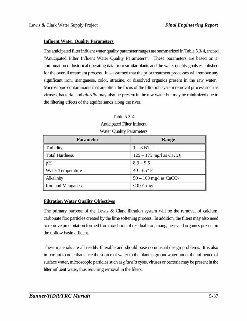
The anticipated filter influent water quality parameter ranges are summarized in Table 5.3-4, entitled “Anticipated Filter Influent Water Quality Parameters”. These parameters are based on a combination of historical operating data from similar plants and the water quality goals established for the overall treatment process. It is assumed that the prior treatment processes will remove any significant iron, manganese, color, atrazine, or dissolved organics present in the raw water. Microscopic contaminants that are often the focus of the filtration system removal process such as viruses, bacteria, and giardia may also be present in the raw water but may be minimized due to the filtering effects of the aquifer sands along the river.
Table 5.3-4
Anticipated Filter Influent Water Quality Parameters
Parameter Range
Turbidity 1 – 3 NTU
Total Hardness 125 – 175 mg/l as CaCO3
pH 8.3 – 9.5
Water Temperature 40 - 65° F
Alkalinity 50 – 100 mg/l as CaCO3
Iron and Manganese < 0.01 mg/l
Filtration Water Quality Objectives
The primary purpose of the Lewis & Clark filtration system will be the removal of calcium carbonate floc particles created by the lime softening process. In addition, the filters may also need to remove precipitation formed from oxidation of residual iron, manganese and organics present in the upflow basin effluent. These materials are all readily filterable and should pose no unusual design problems. It is also important to note that since the source of water to the plant is groundwater under the influence of surface water, microscopic particles such as giardia cysts, viruses or bacteria may be present in the filter influent water, thus requiring removal in the filters.

Lewis & Clark Water Supply Project Final Engineering Report
Banner/HDR/TRC Mariah 5-38
Filter Operating Requirements
In general, the filtration system used at Lewis & Clark must be capable of meeting several general operating requirements. These general operating requirements must be compatible with the treatment processes both upstream and downstream of the filters. The general requirements for the Lewis & Clark filters must address a number of issues, including: regulatory limits in Section 3, as well as number of filter units, length of filter runs, out of service limitations, hydraulic limitations, and flow control requirements. Number of Filter Units
Multiple filter units must be provided for the plant with sufficient number to permit removing a unit from service without compromising the design criteria established for the filters. The number of filter units required will also depend upon the type of filter technology employed. Each filter type has inherent practical limitations on the size and capacity of each unit that will affect overall number of filters. Ten States Standards have established minimum number of filter requirements that vary with the type of filter technology employed. In general, these regulations require a minimum of two filter units. Length of Filter Runs
Most water plant filters operate as batch systems, regardless of the type of technology employed. The filter serves to treat a limited volume of water, and then must be backwashed or cleaned before it can be returned to service. The length of filter run will be dependent upon a number of variables, including: surface loading rate, water temperature, depth of solids penetration, media distribution and pretreatment provided. In general, the normal filter run lengths should be long enough to avoid hampering overall plant operations due to frequent filter cleaning or cause excessive use of plant water production for cleaning operations. The filter run lengths should also not be so long as to permit biological growth in the filter or interfere with routine operating shifts at the plant. Filter run lengths of up to 100 hours are not unusual. For purposes of this design report, a 72-hour filter run time will be used for average treatment flows and a 48-hour filter run time will be used for maximum treatment flows.
Out of Service Limitations
Due to the nature of filter operations and the potential for equipment malfunctions, some allowances should be provided for taking filter units out of service for maintenance. These provisions are
Lewis & Clark Water Supply Project Final Engineering Report
Banner/HDR/TRC Mariah 5-39
in addition to those provided to take the filters off-line for routine cleaning. The capability to remove individual filter units from service for extended periods of time must be provided, without requiring unusual measures to operate the remaining filters still in service. Filter loading rates may need to be increased above the established design parameters if a filter is out of service for an extended period, and thus be capable of hydraulically handling the increased flow. The reduced filter run lengths and increased frequency of backwash should not overburden the filtration system or waste handling system at the plant. Ten States Standards requires that the filter system be capable of meeting the plant design capacity at the approved filtration rate with one unit out of service. On large plants, with a large number of filters, it is often a common practice to establish the filtration requirements with two filters assumed out of service. For Lewis & Clark, one unit will be assumed to be out of service for backwashing at maximum day flow conditions. Hydraulic Limitations
The treatment units prior to the filtration system will utilize gravity flow to pass flow through each of the succeeding units. Approximately 6-8 feet of head will be used from the future pretreatment basins to the effluent of the upflow basins. The flow received by the filtration system will be at atmospheric pressure. If gravity filters are employed, the downstream plant hydraulics will be set to provide sufficient head through the filters without intermediate pumping. Should pressure filters be utilized, booster pumps would take suction from the effluent of the upflow or recarbonation basins, raising the hydraulic grade line to account for the high head losses through the pressure filters. The downstream hydraulics of the plant could be set independent of the hydraulics upstream of the pressure filters, making plant layout more flexible. However, for gravity filters approximately 10-12 feet of head should be provided for in the plant hydraulics for head loss through the filters. This head loss would provide sufficient allowance for normal operation of gravity filters. Flow Control Requirements
All flow received by the filters must be treated at the rate being received. The filter system must automatically adjust to changes in plant flow, maintaining stable conditions within the filter units. Intermediate storage or bypass of the flow is often not normally required. If intermediate storage is utilized, it is usually provided by employing submerged orifice effluent troughs in lieu of overflow weir troughs on the softening basins preceding the filters. The submerged orifice troughs permit the buildup of water in the basin to avoid temporary changes in filtration rates should a filter be removed from service for a short period.

Lewis & Clark Water Supply Project Final Engineering Report
Banner/HDR/TRC Mariah 5-40
However, submerged orifice troughs do not collect basin effluent as evenly as overflow troughs and may reduce the final softening basin’s efficiency. Submerged orifices will not be used at Lewis & Clark. Another approach to maintaining even flows through the filters during short-term periods when a filter(s) is removed from service for cleaning is to bring previously cleaned filters back on-line at the same time a dirty filter is removed from service. This requires that a filter that has been cleaned set idle until another filter needs to be cleaned, but allows maintenance of a steady flow through the filters already on-line. With this approach, overflow weir troughs can be used in the final softening basin. In the event the idle filter is returned to service prior to removing another filter from service, the automatic filter flow controls would need to evenly distribute the change in flow among the active filters. 5.3.4.2. Filtration Technologies Filtration systems employed at water treatment facilities utilize a porous medium through which the water passes to remove suspended solids. A number of methodologies have been developed to accomplish this purpose. Currently, the most commonly used approach to filtration in water treatment plants similar to Lewis & Clark is rapid rate gravity filters. However, recent developments in filtration technology have increased the popularity of other types of filter systems. As a result, it is considered appropriate to review the available technologies to determine the optimum filtration system for Lewis & Clark.
5.3.4.2.1. Types of Filters Available
Two types of filtration systems are deemed technically feasible for Lewis & Clark. The following are system types that have been identified for possible consideration at the Lewis & Clark facilities:
? Rapid rate gravity filtration ? Rapid rate pressure filtration
Gravity Filtration Systems
Gravity filters operate with relatively low hydraulic head losses through the unit, while the pressure filters are more practical where higher head losses are advantageous. Pressure filters
Lewis & Clark Water Supply Project Final Engineering Report
Banner/HDR/TRC Mariah 5-41
allow pumping through the unit at relatively high pressures, and are commonly used in small plants where they tend to be more economical. In larger plants, gravity filters are more prevalent, as pressure systems are limited by available vessel sizes. A significant concern with pressure filters is the inability to observe the filter during routine operation, particularly during cleaning of the filter.
Rapid Rate Gravity Filtration
Rapid rate gravity filtration is the most widely used technology for removing turbidity and microbial contaminants from pretreated surface water and groundwater. Flow is normally downward, with the pretreated water passing through a granular bed. Solids accumulate within the voids and on the top surface of the filter bed. Plugging of the filter bed gradually occurs resulting in either increased head loss or a reduction in flow through the filter. After a period of operation, the filter bed is cleaned using an upward flow of water or water and air referred to as backwashing. Treatment prior to the filters consisting of chemical precipitation and sedimentation must be provided to reduce the quantity of particulates and assure a more efficient removal of particulates in rapid filters.
Rapid Rate Pressure Filtration
This filter type is similar to the gravity rapid rate filters, except the flow enters and exits the filter under pressure. The filter bed is normally installed in a cylindrical steel pressure vessel, with connecting pressurized piping. The pressure vessel can utilize a vertical or horizontal arrangement. The filtration process is essentially the same as the gravity system, except for the elimination of concerns associated with negative pressures in the filter bed. Pressure filters are normally used in small water systems and industrial applications for iron and manganese removal from groundwater. Their use for filtration of surface waters or lime-softened water is not normally permitted. Ten States Standards precludes their use in both these applications.
Comparison of Filter Systems
Each of the filter types discussed previously has inherent advantages and disadvantages. Of critical importance is the filter systems suitability for use following the lime softening treatment process to be used at Lewis & Clark.
The following is a summary of the advantages and disadvantages for each of the filter types as they relate to Lewis & Clark.

Lewis & Clark Water Supply Project Final Engineering Report
Banner/HDR/TRC Mariah 5-42
Rapid Rate Gravity Filters
Advantages ? Utilizes well-proven technology in use at many plants. ? Can employ gravity flow through filters. ? Capable of handling upsets from softening basins.
Disadvantages
? Pretreatment is required to efficiently remove particulates ? Sensitive to sudden changes in filtration rate ? Can experience negative head conditions
Rapid Rate Pressure Filters
Advantages ? Can utilize higher filtration rates than gravity units ? Allows higher terminal head loss ? Negative pressure cannot occur in the filter medium
Disadvantages
? Requires re-pumping contact basin effluent through the filters ? Pretreatment is required to effectively remove particulates ? Filter media backwash cannot be observed by operator ? Requires large number of filters due to pressure vessel size limitations ? Not permitted for use on lime-softened water by Ten States Standards ? Sensitive to sudden changes in filtration rate
Conclusions
The proposed filtration system for Lewis & Clark must be cost effective to construct and operate. Current water quality goals must be met and the system must be flexible so as to adapt to future changing regulations. Compatibility of the system to lime softening treatment and large plant applications is important. Based on these considerations, the best system for Lewis & Clark is high rate gravity filters for the following reasons:
? Lewis & Clark will utilize a lime softening process and the high rate gravity filtration
system is capable of handling anticipated floc carryover from the softening basins.

Lewis & Clark Water Supply Project Final Engineering Report
Banner/HDR/TRC Mariah 5-43
? The Lewis & Clark WTP is considered a large plant. ? The high rate gravity system is economical to construct and operate when compared
to other technically feasible systems.
The pressure filtration technology does not meet all the requirements for Lewis & Clark. Rapid rate pressure filters require a large number of pressure vessels and high pumping pressures and this causes the construction and operation cost to be high. In addition, their use for filtering lime soda softening process effluent is precluded by Ten States Standards.
5.3.4.3. Basis of Design
The basis of design for Lewis & Clark will need to incorporate a number of considerations. Of particular importance are the following:
? Compliance with Ten States Standards criteria ? Utilization of gravity flow through the filters without intermediate re-pumping ? Suitability for use on a lime-softened groundwater
5.3.4.3.1. Filter Layout
A number of factors must be addressed in developing the layout for the filters at Lewis & Clark. These factors include: overall configuration, number of units, unit sizes, and filter depth.
Configuration
A number of factors will affect the overall filter configuration for Lewis & Clark. The four major factors are:
? filter bed surface area or dimensions ? depth of the filter box ? backwash method ? method of filter control
Lewis & Clark Water Supply Project Final Engineering Report
Banner/HDR/TRC Mariah 5-44
There are other factors that also impact configuration of the filters (i.e., site constraints, materials of construction). Ten States Standards also contains several requirements that must be considered in the filter configurations, including provisions for the following:
? Vertical walls within the filter ? No protrusion of the filter walls into the filter media ? Cover by superstructure as determined necessary under local climate ? Head room to permit normal inspection and operations ? Minimum depth of filter box of 8½ feet ? Minimum water depth over the surface of the filter media of three feet ? Trapped effluent to prevent backflow of air to the bottom of the filters ? Construction to prevent cross connections and common walls between potable and
non-potable water.
One common arrangement for gravity filters is to place the filter units side by side in two rows on opposite sides of a central pipe gallery. This concept allows the filters to be grouped in a separate room isolated from the remainder of the plant. Another arrangement sometimes used is to place the filters in a row opposite the upstream treatment basins, separated by a pipe gallery. There two arrangements are considered the more typical approaches to filter layout. The filters should be located as close as possible to the source of influent water, the backwash water supply, the filtered water storage reservoir and the control room. Some other layouts are possible using less conventional schemes. The valveless filter, often referred to as the “Green-leaf” filter, utilizes clusters of four filters centered around a middle control chamber. Multiple clusters of the filters can be used in a variety of arrangements. This type of filter utilizes the effluent from three filters to backwash the fourth filter, employing the head available in the three producing filters. The primary advantage of the valveless filter concept is the elimination of the complex piping and valving associated with the more traditional gravity filter layouts. However, if a filter must be removed from the service for maintenance, operation of the remaining three filters in the cluster is compromised as sufficient flow for proper backwashing cannot be provided without auxiliary pumping. In addition, the terminal head loss is limited to 3 to 4 feet by the effluent weir and flow splitting between filters is inaccurate due to the use of inlet weirs to control flow to individual filters. Finally, the valveless filter concept does not permit the use of a center gullet to divide the filters into two cells, essentially doubling

Lewis & Clark Water Supply Project Final Engineering Report
Banner/HDR/TRC Mariah 5-45
the number of filters required when compared to the traditional gravity filter layouts. Another filter layout scheme utilizes a low-head continuous backwash concept, employing long rectangular filters. Each filter is subdivided into multiple compartments with the effluent flowing to a common channel. Each filter compartment is washed separately, using a traveling backwash system. The filter is backwashed frequently at low head, using a small backwash pump and wastewater collection system. The continuous backwash filter utilizes a shallow depth sand media, which limits the filter loading rates to 2.0 gpm/ft2, well below the 3.0 to 5.0 gpm/ft2 rate normally utilized for multi-media filters.
Filter Number/Sizing
The number of filters or filter units utilized in a water treatment plant is a function of the overall plant maximum capacity. Ten States Standards requires a minimum of two units, while standard practice is to provide a minimum of at least four filters for large plants. For large-sized plants such as Lewis & Clark, the number of filters is often determined by the maximum filter media area that is practical to construct and operate. Large filters are normally provided with a center gullet to permit backwashing the filter one-half at a time, using common inlet and outlet piping. This approach permits reducing the number of filters and the overall filter system complexity. Although filters larger than 4,000 square feet have been used, normal practice is to limit the total filter size to a maximum of 2,000 square feet to maintain backwash flow rates and filter piping/valve sizes within reasonable limits. This maximum size is also due to difficulties in providing uniform distribution of backwash water over large areas, reduction in filter capacity with one unit out of service for backwashing and structural design considerations. The Lewis & Clark filters will be designed to meet the following requirements:
? Filter a total flow of 29.5 mgd ? Operate with one filter unit out of service for backwashing ? Provide a filter loading rate of 4.0 gpm/ft2 at maximum flow
Lewis & Clark Water Supply Project Final Engineering Report
Banner/HDR/TRC Mariah 5-46
A maximum filtration rate of 4.0 gpm/ft2 is recommended for Lewis & Clark to provide a proper balance between filter run lengths and filter unit sizing. Traditional practice has been to utilize a 4 gpm/ft2 loading rate for dual media filters. However, more recent experience has shown that loading rates as high as 8-10 gpm/ft2 could be utilized on high quality waters (NTU < 1.0). Due to expected turbidity carryover from the softening basins (1-3 NTU), a 4.0 gpm/ft2 maximum loading rate is recommended for Lewis & Clark. Higher loading rates would reduce filter run lengths below acceptable durations and reduce plant flexibility should a filter be out of service for any length of time. The filtration rate at average flow will be approximately 3 gpm/ft2.
Filter sizing for Lewis & Clark is based on the following constraints:
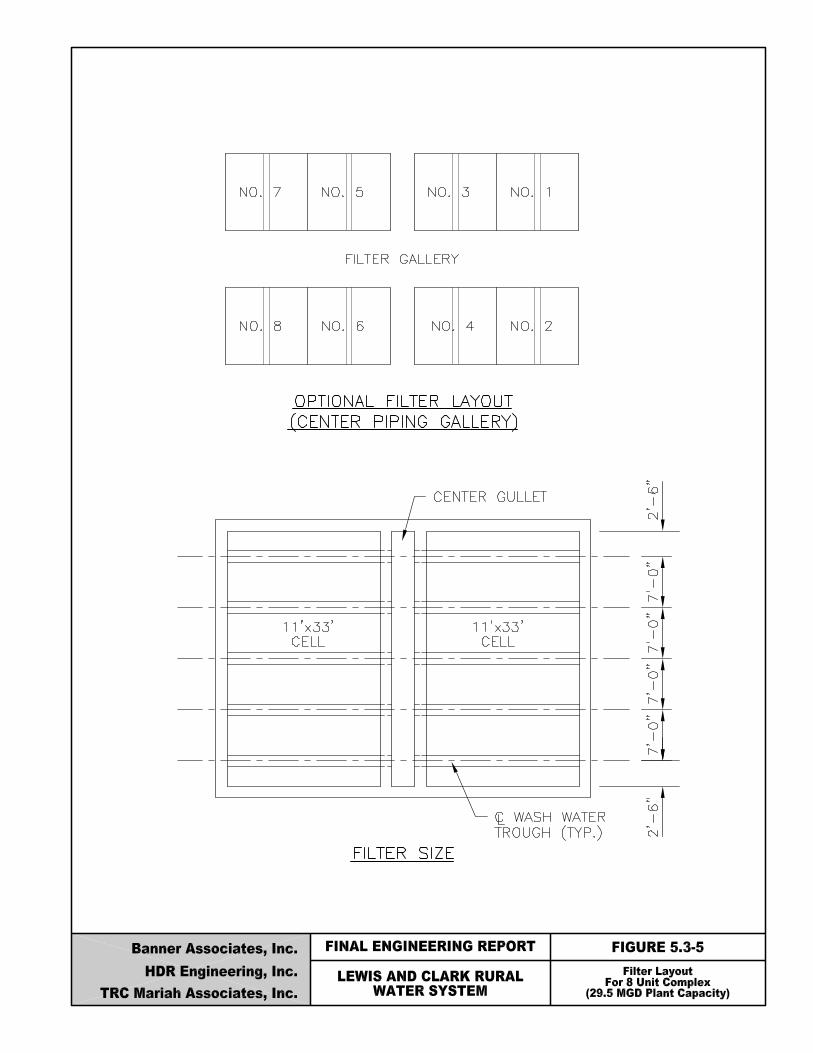
? Utilize rectangular filter cells (3:1 L/W ratios). ? Provide a filter surface area of 600 to 800 square feet (both cells). ? Utilize a filter cell width of 10 to 12 feet. ? Provide 8 filters with 2 cells per filters. ? Provide an even number of filters to provide for optimum filter system layout.
For Lewis & Clark, the use of 8 filters with one out of service is recommended. The recommended filter size is 22 x 33 with each cell 11 x 33. Figure No. 5.3-5 entitled “Filter Layout for 8 Unit Complex”, shows an optional general layout for the recommended filters.

Lewis & Clark Water Supply Project Final Engineering Report
Banner/HDR/TRC Mariah 5-48
Filter Depth
Traditionally, the overall depth of filters from water surface to underdrains has been 8 to 10 feet. Ten States Standards also require a minimum filter box depth of 8½ feet, with a minimum water depth of 3 feet over the filter. The current trend is toward deeper filters, which provide a number of advantages over the traditional filter design:
? Increases submergence above media to prevent air binding. ? Increases depth to accommodate coarse monomedia. ? Provides for higher head losses on high rate filters to assure adequate filter run time.
Normally 10 to 12 feet of head loss is allowed in the plant hydraulics between the water surface above the filter media and the free water level in the filter effluent conduit. The depth of the filter box does not need to account for the total head loss, but should allow a minimum of 5 to 8 feet for build-up of head loss during filter runs. As much as 3 feet of head losses may be required to account for losses through the underdrain orifices, underdrains, effluent piping and valves. The Lewis & Clark filter depth must as a minimum comply with the Ten State Standards requirements identified previously. In addition, the filter depth should allow the plant operators to take full advantage of the filter system inherent capabilities, resulting in a depth greater than the 3 feet over the filter minimum required by Ten States Standards. The increase in water depth will provide more available head to lengthen filter runs and allow flexibility to change to alternate filter media in the future should it become necessary. A minimum water depth of 6 feet above the surface of the filter media should be provided, with 2 to 3 feet of freeboard allowed for in the filter design. The overall depth of the filter box will be affected by the type of underdrain and depth of filter media that are used, so actual depth of filters cannot be finalized until those elements are selected.
Conclusions
Based on a review of several different options for the size and number of the filters, the following configuration is recommended:
Lewis & Clark Water Supply Project Final Engineering Report
Banner/HDR/TRC Mariah 5-49
? Maximum filtration rate of 4 gpm/ft2 at maximum flow with one filter out-of-service. ? Total of 8 filters ? Each filter will be comprised of two cells, each 11 foot wide by 33 foot long. ? The two cells for each filter will be separated by a center gullet. ? Minimum water depth of 6 foot over the media.
5.3.4.3.2. Filter Backwash
Backwashing of filters that have become clogged with particulate matter captured on the grains of fine media and in the pore spaces between grains, can be accomplished in a variety of methods. The traditional backwash system uses treated water wash, with the water introduced into the bottom of the filter bed through the underdrain system to obtain full-bed fluidization. Three basic approaches are normally employed for gravity filter backwashing:
? Treated water wash without auxiliary scour. ? Treated water wash with surface wash. ? Treated water wash with air scour.
For lime softening plants, such as the proposed Lewis & Clark plant, some type of surface wash or air scour is mandatory to prevent encrustation from occurring on the filter media due to calcium carbonate deposition. As a result, performing backwashing without some type of auxiliary scour is not recommended for Lewis & Clark. The two backwash approaches using surface wash and air scour would be acceptable for Lewis & Clark.
Lewis & Clark Water Supply Project Final Engineering Report
Banner/HDR/TRC Mariah 5-50
Types of Backwash Systems
The surface wash assisted wash water system is the most commonly used backwash system for gravity filters. Although fixed nozzles can be used, normal practice is to employ a rotary arm mechanism for the surface wash system, with nozzles located directly above the filter bed. Fixed nozzle assemblies are not normally used as they restrict access to the filter media and are costly to maintain. The advantages of a rotary surface wash system are:
? The system is simple to implement and operate as a source of high-pressure water is
the only auxiliary system needed.
? The equipment is easily accessible for maintenance.
The disadvantages of a surface wash system are:
? The rotary arm can stop rotation, preventing proper cleaning of the filter media.
? The corner areas of the filter chamber are difficult to effectively clean as the rotating nozzles cannot pass directly over the filter surface.
? The surface wash mechanism cleans only at one horizontal plane in the filter,
providing no benefit to cleaning of the bed area further below the mechanisms.
? The surface wash system requires approximately 1-2 gpm/ft2 to operate, increasing plant water production requirements.
An air-assisted backwash system is used in a number of methods to improve the effectiveness of the wash water or to reduce the backwash water flow rates. The air may be used prior to the water backwash or concurrently with the water backwash. Air is introduced through orifices located beneath the filter media. The potential advantages of an air scour auxiliary system are:
? The air scour evenly covers the entire surface area of the filter bed.
? The full depth of the filter media is agitated.
? May reduce the volume of wash water required by shortening the duration of the
wash.
Lewis & Clark Water Supply Project Final Engineering Report
Banner/HDR/TRC Mariah 5-51
The air scour auxiliary disadvantages are:
? The potential for loss of filter media is greater, particularly if simultaneous air scour
and wash water are used. ? Movement of the support gravel is a potential concern if the air is introduced below
the gravel. If filter bottoms are used that do not need a gravel layer, this issue is not a factor.
? The auxiliary system is more complicated as an air blower, piping system and control
system are required.
The most effective backwash is provided by simultaneous air scour and wash water fluidization. However, this method is very susceptible to media loss problems. Using air scour prior to wash water fluidization is considered about the same effectiveness as the use of surface wash with wash water fluidization. Reductions in the volume of backwash wastewater can be accomplished with simultaneous air/water backwash. It is recommended that Lewis & Clark employ air scour assisted backwash, with the air scour terminated prior to the washwater upflow reaching the wash water troughs.
Water/Air Source
The supply of water for the filter backwashing operations is filtered water. There are a number of options for supplying wash water that are commonly used, including:
? Interconnection with the high service pump discharge. ? Gravity flow from an aboveground wash water tank. ? Gravity flow from a higher elevation storage reservoir off-site. ? Pumping from the clearwell.

Lewis & Clark Water Supply Project Final Engineering Report
Banner/HDR/TRC Mariah 5-52
At Lewis & Clark, the primary source of backwash water will be provided by direct pumping from the clearwell. Diverting flow from the high service pump discharge is very inefficient because the backwash pressure is significantly less than the distribution system pressures. Use of a wash water tank can be cost prohibitive due to the limited physical relief at the plant site. A single pumping unit could be utilized to supply backwash water, with a standby pumping unit provided to assure reliability. Pump flow control could be provided by throttling valves in the pump discharge piping or through the use of variable speed drives on the pumping units. The decision on which type of flow control should be used will need to be made as part of the final design of the facility. The supply of air for the air scour will need to be generated by on-site blowers sized for 3 scfm/ft2, with the air piped to the filters. The high flow/low pressure air requirements can be handled by a single blower connected to the filters through a header system. A standby blower would be needed to assure reliability of the backwash system. Each blower would be designed to provide 1,100 scfm (air scour 1 cell at a time).
Wash Water Troughs
Normal practice is to provide evenly distributed wash water troughs above the filter media to collect backwash water and direct flow the washwater gullet and drain system. The troughs serve to equalize head on the underdrains and provide uniform upflow of wash water through the media. The bottom of the trough must be positioned above the expanded zone of the filter media during backwashing to prevent media loss. Traditional design is to space the troughs at 1½ to 2 times the distance between the trough weir and filter media surface. Ten States Standards requires that the horizontal travel of suspended particulates not exceed 3 feet. The spacing must also allow each trough to serve the same amount of filter surface area. The troughs are usually constructed of concrete or fiberglass reinforced plastic and will span the filter chamber to avoid interior filter supports. The proposed 11 x 33 filters at Lewis & Clark would require a total of five wash water troughs per filter cell, with the troughs discharging into the center gullet. The troughs would be designed to permit field leveling of the trough weirs after installation to assure even upflow during backwashing. The layout of the filter troughs within the filters are also shown on Figure No. 5.3-5.
Lewis & Clark Water Supply Project Final Engineering Report
Banner/HDR/TRC Mariah 5-53
Backwash Hydraulics
The required backwash water upflow through the filters is variable and dependent upon a number of factors. These factors include: water temperature, filter media type, and washing method. The rate of flow must be sufficient to fluidize the filter media in order to assure proper cleaning of the filter. To obtain complete expansion of the filter bed may require as much as a 50 percent expansion of the media. However, recent research has shown that optimum cleaning is obtained with 25 to 30 percent expansion. Water viscosity increases with decreasing temperature, increasing friction with the media and lowering the washwater rates needed for bed expansion. As a result, the backwash system must be designed for the warmest water temperature to assure adequate backwash water flow under all operating conditions. Media characteristics impact the washwater flow, increasing with larger media size and higher media density. If more than one type of media is employed, the backwash rate must provide for proper stratification of the filter media. Each method of filter washing has characteristic upflow rates and durations. The design of the underdrain and auxiliary scour systems largely affect the flow rate required. Ten States Standards establishes minimum backwash flow rates that should be employed for rapid rate gravity filters. The provisions include:
? A minimum rate of 15 gallons per minute per square foot, consistent with water
temperatures and specific gravity of the filter media. A rate of 20 gallons per minute per square foot or a rate necessary to provide for a 50 percent expansion of the filter bed is recommended. A reduced rate of 10 gallons per minute per square foot may be acceptable for full depth anthracite or granular activated carbon filters,
? Filtered water provided at the required rate by a backwash pump, from the high
service main, or a combination of these, ? Washwater pumps in duplicate unless an alternate means of obtaining washwater is
available, ? Not less than 15 minutes wash of one filter at the design rate of wash,
Lewis & Clark Water Supply Project Final Engineering Report
Banner/HDR/TRC Mariah 5-54
? A washwater regulator or valve on the main washwater line to obtain the desired rate of filter wash with the washwater valves on the individual filters fully open,
? A rate-of-flow indicator, preferably with a totalizer, on the main washwater line,
located so that it can be easily read by the operator during the washing process, ? Design to prevent rapid changes in backwash water flow.
The head loss through the media and underdrain while backwashing gravity filters typically ranges from 4 to 7 feet, with additional head required to compensate for head losses in the piping system between the backwash pump and the filters and the required static lift.
Air Scour/Fluidization
There are three general approaches to use of air and water filter backwashing:
? Air scour alone followed by low-rate water wash. ? Air scour alone followed by high-rate water wash. ? Simultaneous air scour and water wash.
The first approach noted (separate air scour and low-rate water wash) is not commonly used because bed expansion and stratification are not achieved. Air scour is employed after the filter water level is lowered below the wash water troughs, using a 1-2 scfm/ft2. The low wash water rates assure no disruption to the filter gravel, but provide limited cleaning of the filter media. The second approach utilizes separate air scour and high-rate water wash. This method is similar to the first approach, with the exception that high rate wash water is used. Air scour rates of 3 to 5 scfm/ft2 and wash water rates of 15 to 23 gpm/ft2 are normally used for this backwashing method. This approach is the most commonly utilized of the three air scour methods.
Lewis & Clark Water Supply Project Final Engineering Report
Banner/HDR/TRC Mariah 5-55
The third and final approach is employing air scour and wash water simultaneously to backwash the filter bed. Air scour rates of 2 to 4 scfm/ft2 and wash water rates of 8 to 12 gpm/ft2 are used with this method. Wash water trough baffling is required with this scheme to prevent the loss of filter media during backwash. Wash water volumes are reduced by 30 to 50 percent when compared to the separate air scour and high-rate wash water method. At the completion of the backwashing cycle, the bed must be restratified at a wash water rate of 12 to 15 gpm/ft2, without the air scour system in operation. For Lewis & Clark, the first backwashing approach discussed above will not provide adequate bed cleaning and restratification. The third backwashing approach has significant potential for media loss. Although the reduction in backwash water volume is of benefit with the third approach, it does not dictate that this approach be used. As a result, the second backwashing approach, use of separate air scour and high-rate water wash is recommended for Lewis & Clark. This approach provides the most trouble-free operation. However, the filter control system will provide sufficient flexibility to allow the plant operators to utilize the other backwashing approaches also, if desired.
Filter to Waste
Ten States Standards recommends but does not require provisions for filter to waste capability in the filter effluent. The purpose of this type of system is to waste filter effluent at the start of each filter cycle after the completion of backwashing until the filter effluent turbidity level drops to an acceptable level. The presence of high turbidity levels in the filter effluent at the startup of a filter after backwash is more than just a “ripening” process. It is viewed as a flushing out of remnant backwash solids and material released during particle collisions during the closure of the backwash valves. A 2 to 20 minute period may be required for filter-to-waste depending on the pretreatment effectiveness. The use of filter-to-waste has gained renewed interest in the past several years on surface water supplies that contain Giardia cysts or cryptosporidium. During normal startup of a filter, turbidity passage is small when averaged with the effluent turbidity of the other filters. However, Giardia and cryptosporidium are a concern even at low levels, so they may pose a health risk when passed through only one filter. Because Lewis & Clark will employ a groundwater supply under the influence of surface water, the continual presence of microbial contaminants in the raw water must be anticipated. Thus, capability to filter to waste will be provided as necessary. The filter to waste piping will need to discharge to

Lewis & Clark Water Supply Project Final Engineering Report
Banner/HDR/TRC Mariah 5-56
a separate section of the backwash retention basin. Since this flow is of a higher quality than the backwash water, providing a separate holding compartment will allow this flow to be recycled to locations in the treatment system independently of the treated backwash. The volume of filter to waste flow is approximately 55,000 gallons per backwash per filter, assuming a 20-minute time period.
Conclusions
A number of potential options have been identified to the filter backwash system of Lewis & Clark. Based on the evaluations of each of these options, the following is recommended for the Lewis & Clark backwashing system.
? Use of treated water wash employing air scour for filter backwash.
? Use of water pumped from the plant clearwell for wash water supply.
? Use of separate air scour at 3 to 5 scfm/ft2 and high-rate wash water at 22 gpm/ft2
during backwash sequence
? Providing filter to waste capability
5.3.4.3.3. Filter Control Logic
There are two basic methods of operating gravity filters that differ primarily in the way that the flow is applied across the filter. These methods are referred to as constant rate filtration (CRF) and declining rate filtration (DRF). CRF is the most widely employed method in the water industry, with either the influent or effluent flow controlled through each filter. This approach usually limits the maximum flow through the filter beds, minimizing rapid flow changes to prevent surges that can disrupt the filter bed. With DRF, the filter configuration is similar to CRF, except all filters discharge to a common effluent pipe or channel without use of flow control valves. Water levels in the filters are at a common level, with flow allowed to vary depending on how clean the individual filter beds are at the time. With CRF there are three ways a filter can be operated: 1) influent flow splitting with constant water level; 2) influent flow splitting with varying water level; and, 3) a rate-of-flow controller in the filtered water piping. Figure No. 5.3-6 entitled “Alternative Filtration Control Systems”, illustrates these three methods of control and that of DRF. The following is a brief description of the CRF and DRF filters.

Lewis & Clark Water Supply Project Final Engineering Report
Banner/HDR/TRC Mariah 5-58
Constant Rate – Influent Flow Splitting with Constant Level
This method of control generally uses individual weirs in the header channel entrance to each filter. The channel hydraulics and weir lengths must be carefully designed and generously sized so that equal flow splitting occurs. The constant level is maintained by means of a level element in each filter. The level element sends signals to a modulating valve in the filter effluent line to control the total system head loss through the filter, and thus, maintain a constant level. At the start of the filter run, the valve is only partially open so that the total head loss through the filter media, underdrain, gullet, piping, and control valve is equal to the total available filter head at the set water level in the filter. As the head losses increase due to accumulation of particulate matter, the level tends to rise to maintain the flow through the filter. The level element then sends a signal to the valve, which opens to maintain the constant total head loss, thereby maintaining a constant level in the filter. When the flow to the filters increases due to backwashing other filters or increased plant flow, the level element signals the modulating valve to adjust accordingly.
The advantages of this type of filter operation are:
? Operator has control of the system. ? Filter flow element not needed. ? Can respond gradually to flow variations. ? Filter aid such as polyphosphate easy to apply.
The disadvantages are:
? Influent header channel and weir require careful hydraulic design to provide equal flow split.
? Added cost of channel width and weir. ? Head loss over weir. ? Level element and modulating control valve required in each filter. ? Operator does not know flow through each filter, i.e., if flow is split equally. ? Floc may break up at weir.
Constant Rate – Influent Flow Splitting with Increasing Water Level
This control method is similar to the other influent flow splitting method except that there are no level elements, controllers, or modulating valves. At the start of a filter run, the water level is

Lewis & Clark Water Supply Project Final Engineering Report
Banner/HDR/TRC Mariah 5-59
above the filter media. Filters of this type normally discharge over an effluent weir, eliminating the possibility of bed dewatering. During a filter run, as the filter clogs, the water rises to overcome the head loss created by the clogged filter media. Changes in plant flow due to backwashing other filters or changing flow in the plant will cause the water level in the filters to rise or fall accordingly. The advantages of this type of filter operation are:
? Filter effluent valve is a simple on-off type. ? Controls are simple. ? Filter flow or level element not necessary. ? Filter aid easy to apply.
The disadvantages are:
? Head loss over weir. ? Channel and weir costs can be high. ? Filter box must be deeper. ? Floc may break up at weir.
Constant Rate – Rate-of-Flow Controlled
With this type of control, the water level in all filters and, generally, the filter header channel are maintained at a constant level. Flow in all filters is controlled by means of a flow meter and control valve in the filter effluent piping. A level element monitors the water level in the influent channel. A controller trims the control valves to maintain each filter flow to a set point. During a filter run, the rate-of-flow controller maintains the flow through the filters at a set rate. As the filter clogs, the head loss through the filter increases which reduces the flow. The controller senses the decrease in flow and opens the control valve to adjust for the increased head in the filter to maintain the set flow rate. The master level control in the influent channel senses variations in the water level in the channel, due to increased

Lewis & Clark Water Supply Project Final Engineering Report
Banner/HDR/TRC Mariah 5-60
plant flow or the backwashing of a filter, and increases the set point flow through the rate-of-flow controllers. The normal operating level range of this type of filter is about six inches. This range is wide enough so as not to shock the filter with surges. The advantages of this type of filter operation are:
? Operator has full manual and/or automatic control of the filter system. ? Operator can vary the flow through any filter. ? Filter box can be designed shallower. ? Can be fully automated. ? No weir head and free-fall allowance needed. ? Can ramp flow at start of filter run. ? Responds gradually to plant flow variation. ? Filter aid easy to apply.
The disadvantages are:
? Added cost of a rate-of-flow controller. ? Additional metering and control equipment needed.
Declining Rate
With DRF, the rate of filtration varies in each filter during a filter run, between each backwash. The filtration rate usually varies between 70% and 130% of the average filtration rate to the filter. When a newly cleaned filter in a group of filters is placed in service following its backwash, it will operate at highest average filtration rate of all the filters until the next filter to be backwashed is cleaned and put back into service. When the backwashed filter is placed back in service, the filtration rate in the filter under consideration will decline in a step-wise manner, to a new lower filtration rate. This rise and fall motion of the water level over the filters will continue along with the stepped decline in the filtration rate until the filter is the last filter to be backwashed, at which time it will be filtering at its lowest rate. During this cycle, the water level in all other filters will rise in unison.

Lewis & Clark Water Supply Project Final Engineering Report
Banner/HDR/TRC Mariah 5-61
The advantages of this type of filter operation are:
? Operation is simpler. ? Less filtering head required for filter runs of equal length. ? No weir head and free-fall allowance needed. ? Hydraulically responds well to plant flow variations.
The disadvantages are:
? Requires continual manual surveillance or controls must be added. ? Difficult to effectively use a filter aid. ? Filter box must be deeper. ? Less likely to be effective at higher filtration rates. ? Influent header channel and valves must be proportionally larger, and therefore, more
expensive. ? The initial high rate of flow into the filter box can cause media migration. ? Operator has little control flexibility.
Conclusions
Each of the four options for filter control logic at Lewis & Clark are potentially feasible for the overall plant treatment scheme previously identified. However, the constant rate-of-flow controlled scheme is considered the most suitable type of control for Lewis & Clark for the following reasons:
? Provides ability to control flow through each filter ? Does not cause floc breakup on filter influent water ? Allows gradual changes of flow through filters.
5.3.4.3.4. Filter Media The most commonly used filter media for water treatment are natural silica sand and crushed anthracite coal. Garnet and illuminate are also used, but not as frequently. A number of variables must be considered in selecting the filter media to be used at Lewis & Clark, including:
Lewis & Clark Water Supply Project Final Engineering Report
Banner/HDR/TRC Mariah 5-62
? Types of media to be utilized ? Depth of each media type ? Effective size range for each media ? Uniformity coefficient for each media ? Specific gravity of each media type
Filter Media Type
There are a number of granular-bed filter types of commonly used for potable water treatment. For filter systems like that required for Lewis & Clark, there are several filter media options:
? Single media sand ? Single media anthracite ? Dual media sand and anthracite ? Mixed or triple media sand, anthracite and illuminate or garnet
Single media sand filters are not feasible for Lewis & Clark due to the low loading rates (2 gpm/ft2) and resultant large surface area required. Single media anthracite, also referred to as mono-media, requires a greater bed depth than the other filter types, increasing the filter box depth and overall cost of the facility. Both dual media and mixed media would be practical for the Lewis & Clark filters. Research has indicated that the performance of both dual and mixed media is similar at rates of 2 to 7 gpm/ft2.
Filter Media Characteristics
Selection of filter media must take into consideration a number of properties, including: size, shape, density, hardness, and porosity. Filter media size is most commonly defined by effective size (ES) and uniformity coefficient (UC). Both ES and UC are determined by gradation analysis and are defined as follows:
ES - dimension exceeded by all but the finest 10 percent (by weight) of the sample
UC - ratio of the 60 percent finer size to the effective size.
The shape of filter media is difficult to quantify, with no accepted procedures developed by the industry to measure media shape. As a result, media shape is normally overlooked when
Lewis & Clark Water Supply Project Final Engineering Report
Banner/HDR/TRC Mariah 5-63
establishing filter media characteristics. Another media characteristic, density, can be readily determined using standard methods. It is an important factor as it affects the bed fluidization requirements for backwashing. Hardness is a measure of media durability and is usually indicated in terms of Mohs hardness. The test is particularly critical for anthracite filter media as it is more fragile than the hard sand grains. Filter media porosity is a measure of void volume compared to total bed volume. Porosity affects the media’s solids holding capacity, head loss, and fluidization flow requirements. Filter Media Selection
The selection of filter media size and depth and the filtration rate are all interrelated. In general, filter effluent quality is improved with finer media, greater media depth, or lower filtration rates. However, filter head loss is increased by finer media, greater media depth, or higher filtration rates. The selection of filter media is also affected by the backwash approach to be utilized. Selection of the media can best be accomplished through experimentation using pilot filters with various filter medias. However, some preliminary media evaluations can be conducted utilizing an empirical approach. For example, with dual media filters, the desired ratio of anthracite ES to sand ES is 2.0, with ratios as high as 3.0 commonly used. Assuming an anthracite effective size of 1.00 mm, the sand layer should employ material with an effective size of 0.50 mm. The relationship between media depth (l) and effective size (d) is also commonly used to select filter media. For dual media filters, the l/d ratio desired is approximately 1200. Assuming a 12-inch sand layer with a 0.50 mm effective size, a 24-inch layer of 1.00 mm ES anthracite would be required. Shallower depths of filter media may be feasible for Lewis & Clark (i.e., 12 inches of sand with 18 inches of anthracite), but the 12-inch sand/24-inch anthracite combination should be used for developing the preliminary filter layouts. Ten States Standards establishes a number of criteria that affect the selection of the filter media. The key requirements are:

Lewis & Clark Water Supply Project Final Engineering Report
Banner/HDR/TRC Mariah 5-64
? A total depth of not less than 24 inches and generally not more than 30 inches. ? An effective size range of the smallest material no greater than 0.45 mm to 0.55 mm. ? A minimum of 12 inches of media with an effective size range no greater than 0.45
mm to 0.55 mm, and a specific gravity greater than other filtering materials within the filter.
? A uniformity coefficient of the smallest material not greater than 1.65. These standards also establish specific requirements for dual media filters. Anthracite
? Effective size of 0.45 mm – 0.55 mm with uniformity coefficient not greater than 1.65 when used alone,
? Effective size of 0.8 mm – 1.2 mm with a uniformity coefficient not greater than 1.85 when used as a cap,
? Effective size for anthracite used on potable groundwater for iron and manganese removal only shall be a maximum of 0.8 mm (effective sizes greater than 0.8 mm may be approved based upon on-site pilot plant studies).
Sand
? Effective size of 0.45 mm to 0.55 mm, ? Uniformity coefficient of not greater than 1.65.
Ten States Standards allows the flexibility to deviate from the above requirements, if experimental data specific to the project can be provided.
Conclusions
Based on the success of dual media filters at other similar plants and the requirements of Ten States Standards, the recommended preliminary media specifications for Lewis & Clark would be a dual media having the following characteristics: Media Depth ES UC Sand 12” 0.50 mm 1.40< Anthracite 24” 1.00 mm 1.50<
Lewis & Clark Water Supply Project Final Engineering Report
Banner/HDR/TRC Mariah 5-65
These specifications are within the ranges allowable by Ten States and the State of South Dakota. HDR has found that media using the above specifications perform well on lime-softening facilities.
5.3.4.3.5. Filter Underdrains
A number of types of underdrain systems are available, differing basically with respect to the type of filter washing system and whether a gravel layer between the media and underdrain is employed. The air-scour filter underdrains for Lewis & Clark are needed to perform a variety of functions, including:
? Supporting and retaining the filter media. ? Distribution of backwash supply water and air scour. ? Collection of flow through the filter bed.
The underdrain design must be capable of uniformly distributing backwash water and air scour across the filter bed and uniformly collecting filtered water over the entire area of the filter. There are four categories of filter underdrain systems available:
? False filter bottom type ? Block filter bottom type ? Pipe lateral type ? Lateral type with media retaining panels
False Filter Bottoms
The false filter bottom underdrain system utilizes a false floor within the filter chamber to mount the underdrain system. A plenum is provided under the false bottom to transport water and air to and from the underdrain. The false bottom is normally a precast or cast-in-place concrete system supported by pedestals off the filter chamber floor. Less commonly used are false bottoms constructed of metal plate. The underdrain associated with the false bottoms can take a variety of forms:
? Strainer-type ? Inverted pyramidal depression with balls (Wheeler bottoms) ? Porous plate type
Lewis & Clark Water Supply Project Final Engineering Report
Banner/HDR/TRC Mariah 5-66
The strainer-type system employs a number of different strainers, constructed of plastic or stainless steel. The strainers contain orifices to equalize backwash flow over the filter bed, and drop pipes to control the inlet of air through the nozzle. The porous plate type underdrains are made of fused silicas or aluminum oxide particles. They are formed into plates and mounted on piers, and allow flow to pass through the entire plate structure. The Wheeler bottom is built with interconnected modules, each module containing four inverted pyramidal spaces. Porcelain balls are positioned in the pyramid space to diffuse flow into the gravel. A porcelain thimble at the apex of each pyramid admits water to the plenum beneath the modules. The strainer type and porous plate type of underdrain do not require an overlying gravel layer, whereas the Wheeler bottom requires the gravel to maintain the filter media in place. The strainer-type and porous plate type underdrain utilize fine openings to prevent the migration of media into the plenum. Normally, strainer-type systems are used for combined air-water backwash systems, while the porous plate and Wheeler bottom underdrains are used for backwash systems not utilizing air-scour. Block Filter Bottoms
This type of underdrain system is composed of vitrified clay or plastic blocks, mounted directly on the floor of the filter chamber. The top surface of the block contains closely spaced orifices. The clay blocks are designed for water wash and the plastic blocks for combination air/water backwash. The clay blocks are designed with dual manifold configuration, with water entering the lower conduit and flowing into the upper conduit along the entire length of the block manifold. The plastic blocks utilize triangular passages. As an alternative, filter blocks are available which utilize strainer nozzles mounted in the top of the block. Plastic blocks are also available with a porous plate of sintered plastic (HDPE) beads attached to the top of the blocks. The porous plate retains the media, allows flow of water into the block and diffuses the backwash flow across the filter bed. It also serves to uniformly distribute the air backwash. Use of porous plates following lime softening is only recommended if pH to the filter is controlled to prevent plugging of the porous plate. At Lewis & Clark, the softening basin effluent is recarbonated to adjust the pH prior to filtration.
Lewis & Clark Water Supply Project Final Engineering Report
Banner/HDR/TRC Mariah 5-67
Pipe Laterals
The pipe lateral underdrain uses a main header pipe embedded in gravel in each filter chamber with several laterals in both sides of the header. The laterals contain perforations on the underside to dissipate flow during backwash against the filter floor and surrounding gravel. The pipe laterals are typically constructed of steel or PVC. The pipe laterals can also be configured using strainer nozzles spaced at intervals along the top of each pipe lateral. Lateral Type with Media Retaining Panels
This system consists of stainless steel or plastic triangular shaped laterals mounted directly on the filter bottom. These laterals allow for collection of filtered water into the laterals through fine well type screen panels in the sloping side walls. This design does not let media pass into the laterals, therefore, a gravel layer is not required. Air and water backwash are introduced into the filtering media through these same well screen panels. The laterals can be sized and located to provide uniform distribution of air/water backwash. Comparison of Underdrain Types
The most commonly used filter underdrain system has traditionally been the block filter bottom. However, recent renewed interest in air/water backwash has increased the use of strainer-type false filter bottoms. In order to determine the most effective underdrain system for Lewis & Clark, a comparison of the advantages and disadvantages for each filter underdrain type suitable for use with air/water backwash is beneficial.
Strainer-type False Bottom Type Advantages
? Does not require a gravel layer. ? Plenum allows access to clean out underdrain.
Disadvantages ? Strainer orifices can become plugged. ? Rupture of the false floor is possible. ? Plastic nozzles are fragile and can easily be broken. ? Dead areas can occur between the nozzles.
Lewis & Clark Water Supply Project Final Engineering Report
Banner/HDR/TRC Mariah 5-68
Plastic Block Type (without cap) Advantages
? Blocks are simple to install in filter chamber. ? Underdrain is not susceptible to rupture problems.
Disadvantages
? Requires use of gravel layer above the blocks. ? Underdrain interior is not accessible for cleaning. ? Disruption of the gravel layer with air is possible.
Plastic Block Type (with porous plate cap)
Advantages ? Blocks are simple to install in filter chamber. ? Underdrain is not susceptible to rupture problems. ? No gravel layer is required. ? Good air distribution. ? Total depth of filter is reduced due to eliminating gravel layer.
Disadvantages
? Underdrain interior not accessible for cleaning. ? System manufactured by only one supplier. ? Use following lime softening requires pH control ahead of filter.
Pipe Lateral Type
Advantages ? Low installation cost. ? Not susceptible to rupture problems.
Disadvantages
? Experiences relatively high head losses. ? Flow distribution is not as effective.
Lateral Type with Media Retaining Panels
Advantages ? Does not require a gravel layer. ? Low profile, allows either deeper media depth or saving in depth.
Lewis & Clark Water Supply Project Final Engineering Report
Banner/HDR/TRC Mariah 5-69
? Designed for simultaneous air/water backwash. ? Corrosion resistant.
Disadvantages
? Relatively new technology without a long history of performance compared to other options.
? Underdrain not accessible for cleaning. ? Small number of manufacturers.
Conclusions
The filter underdrain system for Lewis & Clark must be suitable for use with air/water backwash.
The two most attractive systems for this application are the strainer-type false bottom and plastic block type underdrains. The recommended filter bottom for Lewis & Clark is plastic blocks with porous plate caps. A typical filter section showing the configuration of the filter media is shown on Figure 5.3-7 entitled “Typical Filter Section”.
5.3.5. Disinfection System
Disinfection of potable water is used in conjunction with other treatment processes to inactivate and remove pathogens to provide safe drinking water for the public. Section 4.4.2.3 describes in detail the disinfection process and alternatives. The key parameters used in the design of disinfection systems include: the disinfectant type and contact time (CT). In Section 4.4.2.3.7, chlorine gas is the recommended disinfectant. The following is a summary of the recommended primary and secondary disinfectants:
? Chlorine gas is recommended as the primary disinfectant. Chlorine is a widely used effective
disinfectant with relatively low capital and operation and maintenance costs.
? Chloramines formed with ammonia addition are the recommended secondary disinfectant to maintain disinfection residual in the distribution system. Chloramines have a low potential to produce trihalomethanes and are long-lasting, reducing the need for additional disinfectant to be fed at points throughout the system.


Lewis & Clark Water Supply Project Final Engineering Report
Banner/HDR/TRC Mariah 5-71
Section 5.3.8 describes the chemical feed, storage and handling systems for both chlorine and ammonia. CT is the multiplication of the concentration of the residual disinfectant concentration (C, mg/L) by the contact time (T, minutes) between the point of application of the disinfectant and the point at which the disinfectant residual is measured. The calculated CT must exceed the required CT which is dependent upon various water quality parameters and the disinfectant used. CT must be met with the primary disinfectant. For the Lewis & Clark WTP, the CT will be met using the clearwell as a contact chamber. Table 4.4-32 outlines the CT contact requirements for the conventional lime softening treatment alternative. In the worst case, with a pH = 8.5, and a water temperature of 5°C, the clearwell volume required to meet the CT is 1.19 MG. The clearwell design and sizing are described in more detail in Section 5.3.10.
5.3.6. Future Systems
5.3.6.1. Powdered Activated Carbon Powdered Activated Carbon (PAC) will not be included with the construction of the initial plant but will possibly be added at a later date. PAC has long been used in the water treatment industry for removal or organics associated with color, taste, and odor. Although the raw water for the Lewis & Clark WTP will be taken from wells, it is possible that some concentrations of organics will be present since the water will be influenced by the Missouri River. If color, taste, and odor problems are encountered in the source water, PAC will be used in the treatment process to remove organics. The PAC will be applied into two future rapid mix basins ahead of the solids contact basins. Each basin will be sized for half of the flow from the well field or 15.1 MGD with a detention time of 30 minutes. This detention time will allow adequate contact for adsorption of the organics such as atrazine. Space will be allocated in the facility footprint for the future addition of these facilities. As the name indicates, PAC comes in a dry powdered form. It can be purchased in bags, or in bulk by the truckload. Because of the volume expected to be used for the Lewis & Clark WTP, the most cost effective form to receive the chemical will be the bulk form.

Lewis & Clark Water Supply Project Final Engineering Report
Banner/HDR/TRC Mariah 5-72
The estimated PAC dosage is 20 mg/l. This dosage should keep anticipated levels of atrazine or other organics to below 3 µg/l and remove taste and odors with a factor of safety. The monthly requirement of PAC could be a maximum of 151,200 lbs. The PAC system will in general consist of a bulk storage bin, feeder, eductor and delivery piping. Three systems will be provided, one system to each of the two future pretreatment basins and one backup system. A detailed listing of the PAC system components are as follows:
? Two 76,000 lb storage bins ? Three 10 cu ft/hr volumetric feeders (one standby) ? Three eductors ? One dust collector system for the two storage bins ? Three rotameters for slurry water
A schematic of the PAC system showing how these components fit together is shown on Figure 5.3-8, entitled “Powdered Activated Carbon System Schematic”. PAC will be received in bulk. Unloading will be accomplished by pneumatically conveying the material from the truck to one of the four bins. Each bin is sized to hold one truckload of PAC. A dust collection system connected to each bin will control dust during unloading. PAC will be fed by volumetric feeders from the storage bins into eductors to make a slurry of approximately 2 to 5 percent by weight. The solution will be sent to its application point by the pressure of the eductor water. The eductor method is used to control dust during feeding of PAC by pulling the carbon dust into the water by the partial vacuum generated by the eductor. Approximately 40 gpm will be required for dilution water for the PAC system. The bins, feeders and eductors will be housed in a separate room by themselves adjacent to the pretreatment basins.


Lewis & Clark Water Supply Project Final Engineering Report
Banner/HDR/TRC Mariah 5-74
5.3.6.2. Ultraviolet Disinfection
The stage 2 disinfectant/disinfectant byproducts rule (D/DBP) will impose stricter requirements for the control of disinfectant byproducts (DBPs). The large distribution system resulting in long detention times is conducive to the formation of DBPs. The use of chloramines for secondary disinfection will reduce DPB formation, however the system may still have difficulty complying with the requirements of the rule. Ultraviolet (UV) disinfection does not form disinfection byproducts and therefore may be justified if the system has difficulty maintaining a low concentration of DBPs.
5.3.7. Solids Handling The objective of this Section is to determine the estimated mass of sludge and solids produced at the Lewis & Clark WTP. Sludge production was estimated for evaluation purposes in section 4.4.2.2.6. In this section, a more detailed analysis of sludge production will be presented based on theoretical calculations and includes both the solids contact basins and backwash water. Sludge production will be used later to size the solids handling processes. The basic solids flow schematic is shown in Figure 5.3-9.
5.3.7.1. Solids Contact Basins Solids Characteristics
Estimated sludge production from the solids contact basins at the Lewis & Clark WTP have been calculated. The theoretical calculation is based on an equation from the AWWA Handbook of Practice: Water Treatment Plant Waste Management, 1987. The equation considers average chemical coagulation dosages; average polymer and PAC dosages; average lime dosages; and the removal of suspended solids, iron and manganese.
S = Q(2.0 Ca + TSS + A + Fe + Mn)(8.34 lb/mg/l) Where: S = Sludge produced, lbs dry solids per day Q = Water production, million gallons per day
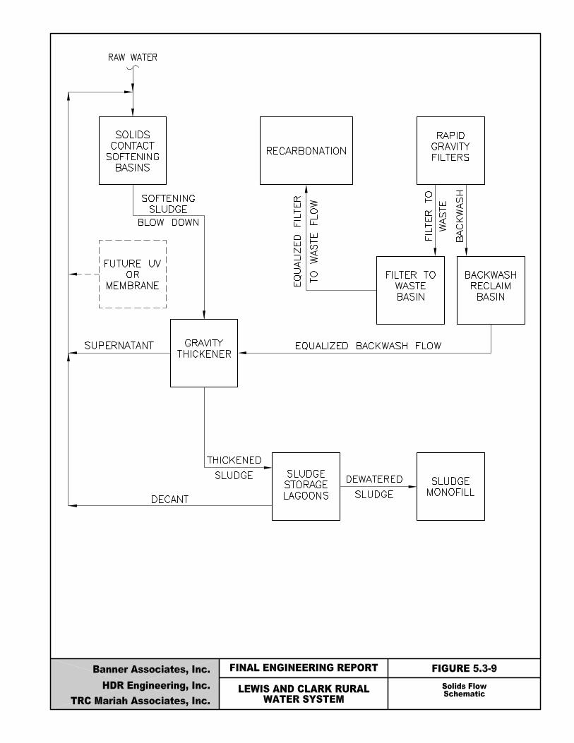

Lewis & Clark Water Supply Project Final Engineering Report
Banner/HDR/TRC Mariah 5-76
Ca = Calcium hardness removed as CaCO3, 135 mg/l. Assumptions made in this calculation are as follows: raw water hardness is 250 to 275 mg/l based on water quality data presented in tables 3.4-1 and 3.4-2, and finished water hardness of 125 mg/L. TSS = Assumed average raw water suspended solids concentration, 2 mg/L A = Additives: Future Powdered Activated Carbon (PAC), 20 mg/L and Ferric Sulfate, 10 mg/L. Pac addition is not included with the initial design, however, it may be included in the future for organics removal, therefore the solids generated by the removal of organics with PAC are included in the estimated sludge production. Polymer is expected to be used in very small doses at the facility and was therefore not included in this calculation. Ferric sulfate is used for coagulation. Approximately 0.66 lbs of sludge is produced per pound of ferric sulfate added. Fe = Average raw water iron concentration, 1.8 mg/L. This number is based on raw water data presented in tables 3-4.1 and 3-4.2. Iron may be precipitated as a carbonate sludge in the softening process or iron will be removed using an oxidant such as potassium permanganate on the total flow in the split treatment-softening mode. Approximately 2.43 lbs of ferric sludge are produced for every pound of ferrous iron oxidized by potassium permanganate. Mn = Average raw water manganese concentration, 0.3 mg/L. This number is based on raw water data presented in tables 3-4.1 and 3-4.2. As with iron, manganese may be precipitated as a carbonate sludge in the softening process, or will be removed using an oxidant such as potassium permanganate on the total flow for the split treatment softening mode. Approximately 2.64 lbs of manganic sludge are produced for every pound of manganous manganese oxidized by potassium permanganate.
The estimated total sludge production is calculated at 2,534 lbs per MG of water produced. The constituents of the sludge and their estimated masses are illustrated in Table 5.3-5.

Lewis & Clark Water Supply Project Final Engineering Report
Banner/HDR/TRC Mariah 5-77
Table 5.3-5 Sludge Constituent Summary
Sludge Constituent Mass, lbs/MG
Calcium Carbonate 2,252
Suspended Solids 17
PAC 167
Ferric Sulfate 55
Iron 36
Manganese 7
TOTAL 2,534
At the average (Year 2030) water production of up to 23.8 mgd, 58,800 lbs/day dry solids will be produced. Sludge production will be 72,500 lbs/day dry solids at the maximum water production of 28.6 mgd. 5.3.7.2. Filter Backwash Water Solids Characteristics The purpose of this section is to evaluate filter backwash water handling at the Lewis & Clark WTP including backwash water volume and quality. Disposal or discharge to a stream is an option, however the intent of this design to reuse as much water as possible and dispose of concentrated solids in the on-site storage lagoons. Discharge would require a NPDES permit from the South DENR. The permit is required to assure that the surface water quality standards described in Table 3.4-3 are not exceeded. Evaluation of discharge to surface waters should be completed during final design. Volume
The total daily volume of filter backwash water generated is based on filter run time and the amount of water used to backwash each filter. The estimated volume of backwash water used per filter (two cells) at the Lewis & Clark WTP is calculated at 290,400 gallons. This volume is based on a filter surface area of 726 SF, 20 gpm/SF filter backwash rate and a 20 minute backwash time. An additional 55,000 gallons of filter to waste water will be generated based on a peak filter loading rate of 4 gpm/SF filter and a 20 minute filter to waste time.

Lewis & Clark Water Supply Project Final Engineering Report
Banner/HDR/TRC Mariah 5-78
The expected maximum daily volume of backwash water is 1.2 million gallons. This volume assumes 48-hour filter runs (minimum filter run time) and 4 filters backwashed per day. The estimated average daily volume of backwash water is 0.784 million gallons. This volume assumes 72 hour filter runs (average filter run) and 2.7 filter backwashes per day. The average daily volume of backwash water is 3.0 percent of the average plant production and the maximum backwash is 4.1 percent of the maximum plant production of 28.6 mgd. The following summarizes the volume of filter backwash water.
? Volume per backwash 290,400 gallons ? Maximum Volume per day 1.2 million gallons ? Average Volume per day 0.8 million gallons ? Filter to Waste Volume 55,000 gallons
Quality
The quality of filter backwash water is important because the amount of solids could adversely impact chemical dosages in the solids contact basins, filter run times and any future consideration of discharge to a nearby stream. The primary concerns are suspended solids, heavy metals and Total Trihalomethanes (TTHMs).
Suspended Solids
The concentration of suspended solids in the backwash is unknown and can only be determined through pilot testing. HDR completed suspended solids tests at a similar treatment facility: Metropolitan Utilities District Platte South Plant. Table 5.3-6 summarizes the results of the tests.
Table 5.3-6
Backwash Suspended Solids
Location Filter Average Suspended Solids (mg/L)
4A 71
4B 69
Omaha, Nebraska Platte South WTF October, 1990 Average 65
Higher concentrations of suspended solids are normally discharged from the filter during the initial phases of a backwash event. Diminished concentrations are encountered as the backwash proceeds. For example, the same study shows that 90% of the solids are discharged to backwash
Lewis & Clark Water Supply Project Final Engineering Report
Banner/HDR/TRC Mariah 5-79
in the first 4 minutes of a 12-minute backwash cycle. The suspended solids concentrations varied from 490 mg/L at the beginning of the backwash to 110 mg/L after two minutes and 20 mg/L or less after 8 minutes.
It is expected that backwashing of filters at the Lewis & Clark WTP will be similar. Most of the solids will come off the filters in the first four minutes of the backwash and the average suspended solids concentration will be around 65 mg/L. Average and maximum total daily solids load in the backwash water is 434 and 651 lbs/day respectively assuming a solids concentration of 65 mg/L. Metals
Heavy metals are a concern because of their toxicity potential. Based on the ground water samples collected as part of the aquifer testing, heavy metal concentrations are well below SDWA MCLs. Softening will also remove metals but at very low levels. Therefore, heavy metals concentrations will also be low in the backwash water and should not adversely impact the plant raw water quality when reused. TTHMs
TTHMs are important to quantify for reuse alternatives since they are suspected human carcinogens. TTHMs are halogen-substituted single carbon compounds, which result from the interaction of free chlorine with certain organic compounds (humic substances) and bromide in the raw water. Since the maximum daily volume of backwash water is only 4.5 to 5.5 percent of the average plant production, the impact of backwash water TTHMs on raw water quality if returned to the plant headworks is expected to be minimal. In summary, the estimated backwash water quality is listed below:
? Suspended solids, heavy metals, and TTHMs in the backwash water will not adversely impact the plant raw water quality if reused or if in the future Lewis & Clark chooses to discharge to a stream.
? Average Suspended Solids Concentration 65 mg/L ? Average Daily Solids 435 lbs/day ? Maximum Daily Solids 650 lbs/day

Lewis & Clark Water Supply Project Final Engineering Report
Banner/HDR/TRC Mariah 5-80
5.3.7.3. Backwash Handling The reuse of backwash water will require returning it to the headworks of the WTP in accordance with the Filter Backwash Rule. Prior to returning to the head of the plant, solids will be removed by sedimentation in a gravity thickener because they could adversely impact the chemical dosages in the solids contact basins and filter run times. Backwash water will flow by gravity from the filters to the backwash reclaim basin. The backwash reclaim basin will act as in equalization structure and will be capable of holding twice the total backwash volume or 580,000 gallons. In this way, two filters could be backwashed consecutively. Flow from the backwash reclaim structure will be pumped at a constant rate to the gravity thickener. Based on a daily maximum backwash volume of 1.2 million gallons, three pumps at 400 gallons per minute each (one pump for standby) will evenly pump backwash to the gravity thickener 24-hours per day. The design capacity will be approximately 600 gpm to allow for operational flexibility. The backwash reclaim basin will be 82 feet square with a total depth of 15 feet. The basin’s sidewater depth after two backwash volumes will be 12 feet, leaving 3 feet available in the basin as a reserve. During final design it may be valuable to review the backwash reclaim basin design to include a smaller basin for the first four minutes of backwash, where most of the solids are removed from the filters. This volume (58,080 gallons per filter) could be fed to the thickener and the remaining volume, (232,320 gallons per filter) could bypass the thickener and go directly to the head of the plant for reuse. This would save on the hydraulic loading to the thickener and still maintain a low solids load to the softening basins, avoiding chemical feed and filter loading upsets. During the first 20 minutes of filtration after a backwash event, the filter goes through a ripening stage. During this stage the filtered water will be wasted back to the a basin so that it can be returned to the recarbonation basins for re-filtering. Similar to the backwash reclaim, the filter to waste basin will also act as an equalization structure and will be capable of holding twice the total filter to waste volume or 115,500 gallons. As indicated, flow from the filter to waste basin would be pumped at a constant rate to the recarbonation basins for re-processing. Based on the maximum number of filter backwashes expected in one day (four) 231,000 gallons will be pumped

Lewis & Clark Water Supply Project Final Engineering Report
Banner/HDR/TRC Mariah 5-81
to the recarbonation basins at a rate of 160 gallons per minute. Two pumps at 200 - 250 gpm will be capable of returning the flow.
The filter to waste basin will be 35 feet square and 15 feet total depth. The following summarizes backwash handling:
? Backwash Reclaim Basin
Length and Width 82 feet Total Depth 15 feet Sidewater Depth 12 feet Discharge Pumps Three installed (one standby) Discharge Pump Capacity 600 gpm each
? Filter to Waste Basin
Length and Width 35 feet Total Depth 15 feet Sidewater Depth 12 feet Discharge Pump Three installed (one standby) Discharge Pump Capacity 200 - 250 gpm each
5.3.7.4. Thickener
Thickening waste solids from a water plant reduces the volume of material to be discharged to the sludge lagoons, thereby decreasing the cost of solids handling. According to the AWWA, the water industry almost exclusively uses gravity thickening even though various thickening processes exist. Therefore, gravity thickening will be evaluated for backwash water and solids contact basin sludge thickening. The design parameters for gravity thickening are solids loading (flux), depth and hydraulic loading.
Design of gravity thickening for lime sludge is based mainly on solids loading rather than hydraulic loading because of the heavy concentration of solids in the sludge. To establish the solids loading, tests can be conducted to determine the settling velocity of the lime and backwash sludge. These data are used to develop a relationship between settling velocity and the initial solids concentration of the sludge. From this relationship the solids flux curve, (lbs solids/SF/day) can be developed to establish the maximum allowable solids loading.

Lewis & Clark Water Supply Project Final Engineering Report
Banner/HDR/TRC Mariah 5-82
For Lewis & Clark these data are not available. However AWWA’s Handbook of Practice: Water Treatment Plant Waste Management, 1987, reports that lime sludges can be thickened in gravity thickeners to 25-30 percent solids concentration at average flow loading rates of 20 to 40 lbs/SF/day. To evaluate the maximum allowable solids loading, Metropolitan Utilities District, Platte South data will be used as a similar facility with similar objectives. Platte South’s solids settling testing data established a maximum solids loading rate of 80 lbs/SF/day. The required gravity thickener surface area is 1,960 SF based on an average solids loading rate of 30 lbs/SF/day and solids load of 58,800 lbs from the softening basins and 440 lbs from the backwash water. This results in a circular thickener with a diameter of 50 feet. This sizing was checked against the established maximum loading rate of 80 lbs/SF/day. Using a solids load of 72,500 lbs from the softening basins and 650 lbs from the backwash water, the maximum loading rate on the thickeners is equal to 37 lbs/SF/day, well below the established 80 lbs/SF/day. Literature reports that gravity thickener surface hydraulic loading rates should not exceed 1.0 gpm/SF. The hydraulic loading on the gravity thickener will include to sludge discharged from the solids contact basins and backwash water. The maximum hydraulic loading to the thickener is 0.49 gpm/SF. This loading rate is comprised of 0.06 gpm/SF from the solids contact basins (72,500 lbs/day of solids at 5 percent solids concentration discharged over a 24-hour period, using a density of 8.34 lbs/gallon), and 0.43 gpm/SF from the backwash water (1.2 million gallons discharged over a 24-hour period). Therefore, the hydraulic loading rate will not exceed the maximum allowable hydraulic loading. Other thickener design criteria include sidewater depths. According to the literature, thickener depths can vary from 12 to 14 feet plus additional depth for sludge storage. At the Lewis & Clark WTP, the sludge storage depth should be sufficient to store the maximum sludge accumulation over the weekend (64 hours). The thickener should have a sludge storage depth sufficient to store solids at one-half the maximum accumulated solids volume of 5,210 CF, assuming a thickened sludge at 30 percent solids and 97,530 lbs of accumulated solids. The required storage depth is 2.6 feet. The total sidewater depth of the thickener will be 16 feet. Of this depth, 13.4 feet will be for thickening and 2.6 feet will be for sludge storage. In summary, the thickener design is as follows:

Lewis & Clark Water Supply Project Final Engineering Report
Banner/HDR/TRC Mariah 5-83
? Surface Area 1,960 SF ? Diameter 50 feet ? Sidewall Depth 16 feet ? Average Solids Loading 30 lbs/SF/day ? Maximum Hydraulic Loading 0.47 gpm/SF
5.3.7.5. Sludge Storage Lagoons The gravity thickened sludge will be stored in lagoons. Sludge will be pumped at 30 percent solids from the gravity thickener to one of three storage lagoons. The combined volume of the lagoons will contain sludge for about 3 years. The following summarizes the design for the sludge storage lagoons.
? Number of lagoons 3 ? Total Lagoon Depth 19 ft ? Lagoon Storage Depth 16 ft ? Storage Volume/Lagoon 1,473,780 CF ? Capacity of each lagoon 471 days ? Volume (3 Lagoons) 4,421,340 CF ? Lagoon Bottom Lining compacted bottom with clay ? Water surface Area 3.2 acres ? Total Estimated Land Requirements 15-17 acres including buffer
Sludge will be pumped to the lagoons 5 days per week, 4 hours per day. Three pumps, each with a capacity of 65 to 80 gpm will be available to pump sludge to the lagoons. One pump will serve as a standby. Each lagoon will operate on a three-year cycle. The first year the lagoon will be filled and the solids will be allowed to thicken further. Decanting structures will be available to decant water from the lagoons at various depths to the head of the plant for reuse. Years two and three the lagoon will no longer be filled. During these years, further thickening and dewatering by evaporation will take place. At the end of the third year, the dewatered sludge will be removed from the lagoon. After the sludge is removed, the lagoon will be made ready to accept sludge and start the three-year cycle over again.

Lewis & Clark Water Supply Project Final Engineering Report
Banner/HDR/TRC Mariah 5-84
5.3.7.6. Monofill
Final disposal of the dewatered sludge from the Lewis & Clark WTP can be either applied to land for agricultural purposes or disposal on-site at a monofill. Since land application for agricultural purposes is area specific and the need for ag-lime in this area is questionable, Lewis & Clark should have provision for monofilling dewatered sludges on-site.
A monofill is a type of landfill, which will require licensing. Landfill licensing and permitting procedures for the Sate of South Dakota are monitored by the Department of Environment and Natural Resources. Rules and regulations for the final design and operation of the landfill will need to be followed.
The method for landfilling evaluated will be the sludge-only trench operation described in the EPA’s Process Design Manual for Municipal Sludge Landfills, 1978. Long wide trenches are constructed to accept sludge. Dewatered sludge is placed entirely below the original ground surface in this type of operation. Excavation of the trenches is normally done by equipment that enters the trench. Soil cover application is usually accomplished by equipment that spreads a layer of cover soil over the sludge. The method of sludge placement may be either from haul vehicles directly entering the trench or from vehicles parked at the top of the trench sidewalls and placing sludge into the trench. Sludge should be dewatered to at least 40 percent solids and preferably 50 percent or greater (maximum of 60 percent is possible in the sludge storage lagoons). The following is a possible design scenario for a sludge-only trench landfill.
? Trench width 60 feet ? Trench depth 8 feet ? Trench length 520 feet ? Distance between cells 30 feet ? Sludge depth per cell 4 feet ? Soil cover thickness 4 to 5 feet ? Sludge application rate 4,300 CY/acre ? Monofill area filling rate 4 acres per year
The estimated land area requirements for landfilling sludges dewatered from the sludge lagoons are 4 acres per year. The space allocated for monofilling on the selected site is approximately 120
Lewis & Clark Water Supply Project Final Engineering Report
Banner/HDR/TRC Mariah 5-85
acres; accounting for 20% buffer the total area for the monofill is 96 acres. At a filling rate of 4 acres per year the monofill area on the existing site will last for approximately 24 years.
5.3.8. Chemical Feed, Storage and Handling Systems
5.3.8.1. General
A water treatment facility is made up of various process units. In order for those process units to function properly, selected chemicals must be fed in the appropriate dosages, and generally without interruption. Chemical feed and storage systems must be able to accurately meter the chemical feed, operate continuously and maintain an adequate supply of chemicals for the treatment processes. This section will present the proposed design of all chemical feed systems to be used at the Lewis & Clark WTP.
Chemical feed systems should be designed such that the feeder(s) are able to provide the average chemical dosage at the treatment plant maximum daily flow on a continuous basis. The plant maximum day finished flow is 28.6 mgd. However, to achieve this finished flow, the plant will have to treat 30.2 MGD because of water losses due to unrecovered waste streams. The chemical handling system should be able to unload a chemical expeditiously from the delivery truck, while maintaining a dust free and safe environment. Each of the dry chemicals delivered in bulk will be provided with dust collectors sized for the truck blowers.
There should be enough on-site storage to provide for 30 days of chemical use at the average dosage and maximum daily plant flow.
The chemical feed, storage and handling systems which are presented in this section and the following one are separated into two categories. First, those which will be provided with the initial construction of the treatment facility and secondly those which may be added at a future date. The following chemicals are proposed for use with the initial construction of the treatment facility.
? Lime ? Ferric sulfate ? Polymer ? Chlorine ? Hydrofluosilicic acid (fluoridation)
Lewis & Clark Water Supply Project Final Engineering Report
Banner/HDR/TRC Mariah 5-86
? Potassium permanganate ? Carbon dioxide (recarbonation) ? Ammonia
The chemical that may be added in the future is:
? Powdered activated carbon PAC may be added at some point in the future if required by additional SDWA regulations or if desired by Lewis & Clark. Provision will be made in the plant layout so that this chemical feed system can be added at a later date. The justification for the use of all of these chemicals in the treatment process were presented in Section 4.4.2.2.7 of the report. A detailed description each of the chemicals, its use, chemical feed equipment needed and the storage system are presented in the following paragraphs. Figure 5.3-10 shows the locations where the chemicals are added in the process.
5.3.8.2. Lime
Lime is a caustic or alkaline material used in water treatment for iron and manganese removal, softening, coagulation and pH adjustment for corrosion control. At the proposed Lewis & Clark WTP lime will be used primarily to adjust the pH for iron/manganese removal and for softening to remove calcium and magnesium hardness from the water. The lime will be added to the softening/blending basins to lower the total hardness from the raw water of up to 275 mg/l to a finished water hardness of 125 - 150 mg/l. The lime also has the secondary benefit of removing organics from the water and improving taste and odor problems. Dry lime comes in two basic forms: Quicklime (calcium oxide) and hydrated lime (calcium hydroxide). Quicklime is primarily used at larger facilities due to its lower cost and ease of handling in bulk form. Hydrated lime is usually used at facilities where smaller amounts are needed.
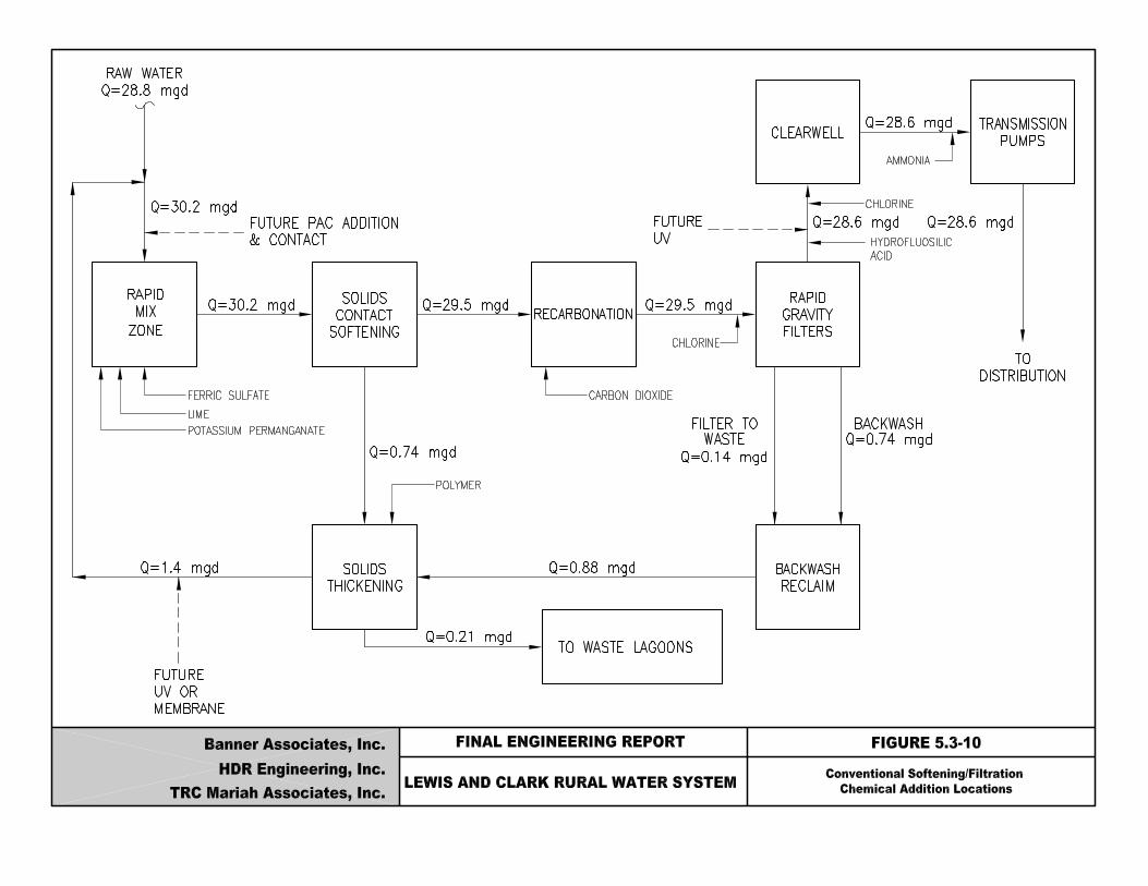
Lewis & Clark Water Supply Project Final Engineering Report
Banner/HDR/TRC Mariah 5-88
Quicklime in a pebble form will be used at the water treatment plant since it will be lower in cost. In order to feed pebble lime it must be slaked, (adding water to convert the calcium oxide to calcium hydroxide). After the pebble lime is slaked, additional water is added, making lime slurry. Once slurried, the lime is fed to the process. The available CaO in the lime should be 94.5 percent or greater. As discussed in Section 5.3.2, the water treatment plant will be designed to operate in two softening modes. In full softening, the entire plant flow will be softened to provide the maximum hardness reduction. For split treatment, one-half or less of the plant flow is softened, resulting in a harder finished water. However, in split treatment, less lime is required and less lime sludge is generated. For the purpose of this section, the full softening mode will be assumed for estimating equipment and storage needs. The lime dosage is estimated to be about 160 mg/l as CaO for full softening. Based on this dosage, the lime system for the water treatment plant will consist of the following components:
? Two 336 ton (7,700 cubic ft) storage bins ? Four 1,000 lb/hr gravimetric feeder (3 duty and 1 standby) ? Four 1,000 lb/hr slakers (3 duty and 1 standby) ? Four rotary inlet valves
Three slakers will be in service under normal circumstances. One slaker for each solids contact basin. A fourth slaker will be provided for standby purposes. Each slaker will supply lime slurry by gravity in open troughs to the center of each solids contact basin. The troughs will be open to allow for easy cleaning due to the build-up of lime. The fourth slaker will serve as a standby unit and will be able to feed to any of the three solids contact basins. Two bins, each with 336 ton capacities will be provided. The bins will provide 30 days storage at a plant flow of 30.2 mgd. Each bin will feed two feeders by gravity through rotary valves which will control lime flow to the feeder. The lime feeder will be a gravimetric type which will feed lime to the slaker. Each feeder and slaker will have a capacity of 1,000 pounds per hour. The feed rate of lime will be controlled by a variable speed drive which adjusts the speed of the feeder belt. The drive may be adjusted manually or automatically to match the influent flow to the basin by a 4-20
Lewis & Clark Water Supply Project Final Engineering Report
Banner/HDR/TRC Mariah 5-89
mA flow signal from the control system. Each slaker may require up to 15 gpm of plant water for slaking. Figure 5.3-11, entitled “Lime System Schematic”, is the schematic of the lime system. Grit removed from the lime slakers will be conveyed to disposal containers in the pipe gallery below via chutes. These containers will be designed so that they can be moved by forklift and taken to the sludge processing facilities and mixed with the sludge for disposal. Another option would be to send this material to public landfill for disposal. The lime will be unloaded pneumatically from the delivery trucks into the bins. Vacuum unloading equipment will be provided near the truck unloading area for this purpose. The system will allow the conveying of lime to any one of the two storage bins. There will be one dust collector to control lime dust during unloadings with a 1,500 CFM capacity. The dust collector will be connected to both bins. 5.3.8.3. Ferric Sulfate
Ferric sulfate is commonly used in water treatment for coagulation. Ferric chloride or alum are also frequently used, however, ferric sulfate is recommended based on the cost and handling requirements. Coagulation is the destabilization of particles in order to allow them to agglomerate for subsequent settling. At the water treatment plant, ferric can be fed along with lime into the solids contact basins to improve coagulation and settling during full softening or split treatment. Ferric is provided in two basic forms for use in water treatment; dry and liquid. Liquid ferric’s main advantages over dry ferric are ease of storage, handling, mixing and feeding. The major drawback of liquid ferric is the added cost of delivery. Liquid ferric is the form proposed for the water treatment plant. The expected dosage is important in the determination of the design of the chemical storage and feed facilities. The expected average dosage is 10 mg/l. This value is based on the dosages used at other water treatment plants with similar raw water quality.

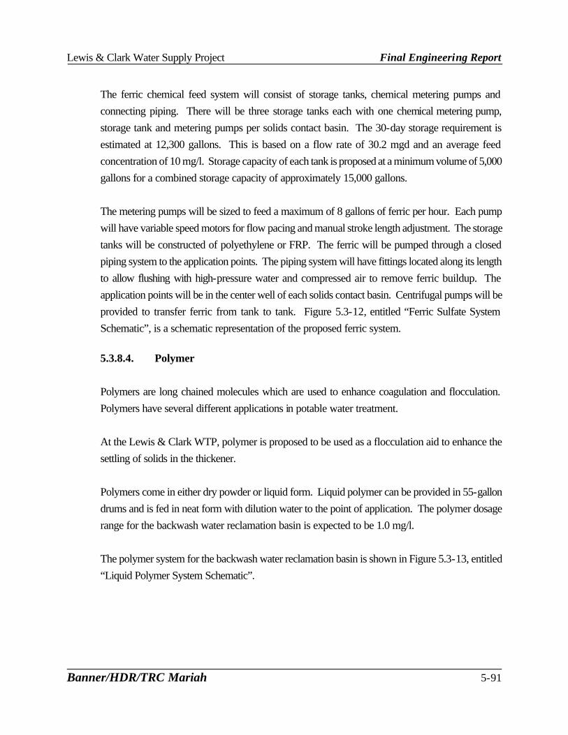
Lewis & Clark Water Supply Project Final Engineering Report
Banner/HDR/TRC Mariah 5-91
The ferric chemical feed system will consist of storage tanks, chemical metering pumps and connecting piping. There will be three storage tanks each with one chemical metering pump, storage tank and metering pumps per solids contact basin. The 30-day storage requirement is estimated at 12,300 gallons. This is based on a flow rate of 30.2 mgd and an average feed concentration of 10 mg/l. Storage capacity of each tank is proposed at a minimum volume of 5,000 gallons for a combined storage capacity of approximately 15,000 gallons. The metering pumps will be sized to feed a maximum of 8 gallons of ferric per hour. Each pump will have variable speed motors for flow pacing and manual stroke length adjustment. The storage tanks will be constructed of polyethylene or FRP. The ferric will be pumped through a closed piping system to the application points. The piping system will have fittings located along its length to allow flushing with high-pressure water and compressed air to remove ferric buildup. The application points will be in the center well of each solids contact basin. Centrifugal pumps will be provided to transfer ferric from tank to tank. Figure 5.3-12, entitled “Ferric Sulfate System Schematic”, is a schematic representation of the proposed ferric system.
5.3.8.4. Polymer Polymers are long chained molecules which are used to enhance coagulation and flocculation. Polymers have several different applications in potable water treatment. At the Lewis & Clark WTP, polymer is proposed to be used as a flocculation aid to enhance the settling of solids in the thickener. Polymers come in either dry powder or liquid form. Liquid polymer can be provided in 55-gallon drums and is fed in neat form with dilution water to the point of application. The polymer dosage range for the backwash water reclamation basin is expected to be 1.0 mg/l. The polymer system for the backwash water reclamation basin is shown in Figure 5.3-13, entitled “Liquid Polymer System Schematic”.

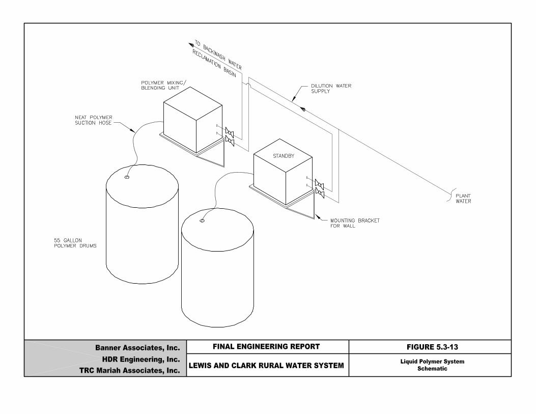
Lewis & Clark Water Supply Project Final Engineering Report
Banner/HDR/TRC Mariah 5-94
A typical system will consist of polymer mixing/blending unit pumping polymer from a 55-gallon drum and mixing the polymer with dilution water and conveying it to the point of application. Typical units are self-contained and consist of a metering pump, dilution water flow meter and solenoid, flash mixing unit, polymer check valve and anti-siphon valve. The units are provided with a control system which can be flow paced. Capacity of the units will be 1 gallon/hour neat polymer feed rate. Dilution water feed rate would be a maximum of 10 gpm. Two units will be provided with one serving as standby. 5.3.8.5. Hydrofluosilicic Acid The addition of fluoride to public water supplies for the purpose of preventing dental cavities. It has long been used as a health practice in the United States and many other countries and will be used at the Lewis & Clark WTP. There are several chemicals which can be used to provide fluoride in drinking water; Sodium Fluoride, Sodium Silicofluoride, and Hydrofluosilicic acid. Hydrofluosilicic acid will be used at the water treatment plant because it is the easiest to use and the most commonly used from of fluoride used today. Hydrofluosilicic acid is received in a 20 to 30 percent water solution. It is a colorless, clear, fuming, corrosive liquid having a pungent odor and irritates the skin. Operators should exercise caution in working around this chemical. Equipment and storage tanks must be acid resistant. By EPA regulations the concentration of fluoride ion cannot exceed 4.0 mg/l in the finished water. The optimum fluoride level in finished water according to the literature is 1.0 mg/l. At this level, the maximum reduction in tooth decay occurs with no aesthetically significant mottling. The raw water fluoride concentration at the Lewis & Clark WTP is 0.4 mg/l. Based on the dosage presented above, the maximum expected fluoride ion dosage will be 0.6 mg/l at Lewis & Clark (maximum finished water concentration minus the minimum raw water concentration: 1.0 mg/l – 0.4 mg/l). This concentration will be used for the design of the fluoride system. At a plant flow of 28.6 mgd, the fluoride addition would be 623 lbs/day. Using the density of 23 percent hydrofluosilicic acid as approximately 10 pounds per gallon, the total volume required per
Lewis & Clark Water Supply Project Final Engineering Report
Banner/HDR/TRC Mariah 5-95
day is 62.3 gallons. At this usage rate, the 30-day requirement would be around 1,870 gallons. With this volume of chemical required, the desired method of delivery would be bulk truckload. The hydrofluosilicic acid system will be comprised of two liquid storage tanks and metering pumps. Two 5,000 gallon storage tanks should be provided. Each tank would hold one truckload delivery. Two tanks are recommended to allow for the removal of one for maintenance. There will be one fluoride application point at the filter effluent. A detailed list of the components are as follows:
? Two 5,000 gallon tanks suitable for storage of 23 percent hydrofluosilicic acid. ? Two metering pumps (one standby), each with 5 gph maximum capacity. ? One transfer pump to move chemical from one tank to the other.
The hydrofluosilicic acid feed system will be isolated from the rest of the chemical feed area. The storage tank will be a fiberglass acid resistant tank having a containment wall around it providing enough volume to contain the entire tank volume should a leak occur. Figure 5.3-14, entitled “Hydrofluosilicic Acid System Schematic”, is a schematic diagram of the hydrofluosilicic acid system. 5.3.8.6. Chlorine The use of chlorine as the primary disinfectant for the Lewis & Clark WTP was discussed in Section 4.4.2.3.7. It is a strong oxidant which has several uses in potable water treatment, the most important of which is disinfection. Other uses include oxidation of iron and manganese and controlling biological growth in treatment processes. The application points are prior to filtration and after filtration before the clearwell influent. Chlorine can be provided in several forms. For the Lewis & Clark WTP, liquefied gas provided in 2,000 lb (one ton) cylinders will be used due to the amount of chlorine to be used and the ease of availability and handling of the 2,000 lb cylinders. The estimated maximum chlorine dosage to be used for the proposed Lewis & Clark treatment plant is 7 mg/l. Of this dosage, 2 mg/l would be fed to the filter influent and 5 mg/l to the clearwell influent.

Lewis & Clark Water Supply Project Final Engineering Report
Banner/HDR/TRC Mariah 5-97
The chlorine feed system will use chlorine as the liquid form from one-ton containers. The basic chlorine system will consist of:
? Three scales for 2 – one ton containers each. ? Three – 2,000 lb/day chlorinators (one spare). ? Two chlorine detectors. ? Provision for allowing installation of future chlorine scrubbers if required, see section
4.4.2.3.1. Figure 5.3-15, entitled “Chlorine System Schematic”, shows a schematic of the chlorine system. For safety reasons, the chlorine feed and storage rooms will be isolated from the rest of the plant. Entry into the rooms will only be from the outside only as recommended by the Ten States Standards. The chlorine storage room will have space available for storing 25 – one ton containers (30-day storage) plus six containers on the scales. Space will be provided for future addition of chlorine scrubbers if required by local building code or local regulatory authority. The chlorine feed and storage rooms have the following special ventilation requirements: 1. Ventilation fan with the capacity to provide one complete air change per minute when the
room is occupied.
2. Ventilation fan must take suction from the floor as far as practical from the door and air inlet, with the point of discharge so located as not to contaminate the air inlets to any rooms or structures.
3. Air inlets must be through louvers near the ceiling.
4. Louvers for chlorine room air intake and exhaust must facilitate air tight closure.
5. Exhaust system will be designed so that chlorine scrubber system can be added in the future.


Lewis & Clark Water Supply Project Final Engineering Report
Banner/HDR/TRC Mariah 5-99
6. Separate switches for the fan and lights must be located outside of chlorine room and at the inspection window. A signal light indicating fan operation must be provided at each entrance when the fan can be controlled from more than one point.
7. Outside switches should be protected from vandalism.
8. Vents from feeders and storage must discharge to outside atmosphere, above grade. Both the feed and storage rooms will be equipped with chlorine detectors. These detectors will sound local and remote alarms in the event of a leak in either room, and cause the evaporators to be shut down. A monorail system will be provided to facilitate unloading of the one-ton containers. An emergency chlorine kit will be provided for making emergency repairs on the one-ton containers and a minimum of two air packs will be provided for entry into either chlorine room in case of a leak. The type or brand of air packs to be used will be selected at the time of final design. A layout of the chlorine facilities is shown on Figure 5.3-16, entitled “Chlorine Facilities Layout”. 5.3.8.7. Ammonia Ammonia is a chemical used in disinfection which will be used at the Lewis & Clark WTP as previously discussed in Section 4.4.2.3. Ammonia is fed in solution form along with free chlorine to form chloramines. Chlorine will still be needed as the primary disinfectant to meet CT requirements. Chloramines are not a strong disinfect and cannot be practically used to meet the primary disinfectant requirements. However, chloramines have two advantages over free chlorine in the distribution system: (1) chloramines are not as volatile as free chlorine, making it easier to maintain a disinfectant residual in the distribution system; and (2) chloramines minimize trihalomethanes formation. Ammonia is available in three forms: Aqua Ammonia, Anhydrous Ammonia and Ammonium Sulfate. Ammonium Sulfate is a solid form of ammonia and is an acceptable form of ammonia for water treatment, however, utilities rarely use it because it is very hygroscopic and tends to cake during feed. Because it is rarely used, and there is the potential for operational problems, it will not be evaluated further.
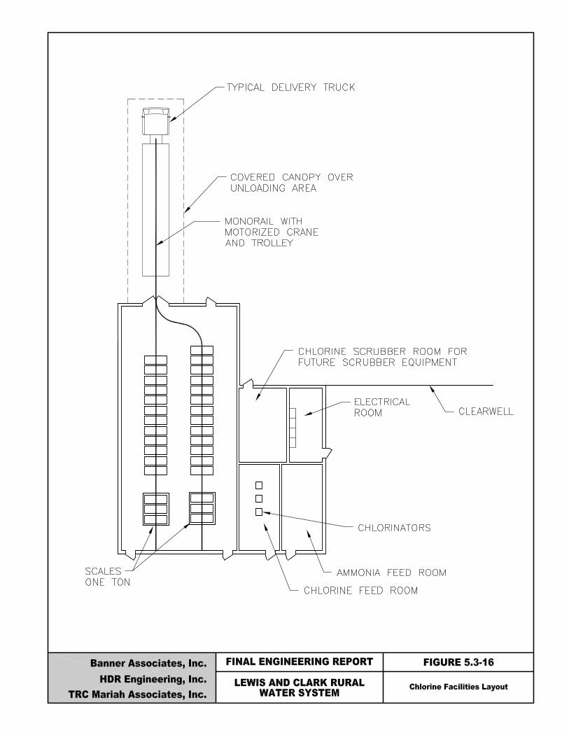
Lewis & Clark Water Supply Project Final Engineering Report
Banner/HDR/TRC Mariah 5-101
Anhydrous ammonia is a colorless gas at atmospheric pressure and temperature conditions. The liquid form of anhydrous ammonia boils at -28°F at atmospheric pressure and is therefore stored under pressure. Anhydrous ammonia feed equipment is similar to chlorine feed equipment, including safety and ventilation equipment. Storage of anhydrous ammonia may require a Risk Management Plan or Process Safety Management Program.
Aqua ammonia is a high pH ammonia solution in water available in concentrations ranging from 19% to 29% ammonia by weight. Twenty nine percent (29%) ammonia will boil at 86°F and may require a risk management program. Given that the boiling point of the 29% solution is less than a typical summer temperature in South Dakota, it would be necessary to store a 29% solution under pressure, adding to the complexity of the system. In contrast, 19% aqua ammonia has a boiling point of 121°F and aqua ammonia solutions less than 20% are exempted from risk management plan requirements.
Nineteen percent (19%) aqua ammonia solution is recommended because using it will not require a risk management plant and will not need to be stored under pressure as would 29% aqua ammonia and anhydrous ammonia.
The ammonia dosage is based on the concentration of chloramine residual desired in the distribution system. One milligram per liter of ammonia reacts with approximately three to four milligrams per liter free chlorine to get an equivalent amount of monochlorine. The proposed dosage for the system is expected to be 0.67 mg/l, which corresponds to the proposed chlorine dosage of 2.0 mg/l based on a 1:3 ammonia-to-chlorine ratio.
The aqua ammonia feed system will consist of a storage tank, chemical metering pumps and a neutralization tank.
There will be two FRP storage tank with a 5,000-gallon capacity (1 truck load delivery). The 30-day storage requirement is 3,250 gallons. This is based on an average feed concentration of 0.67 mg/l, a flow of 28.6 mgd and a specific gravity of 0.93. Two storage tanks are recommended to allow for the removal of one for maintenance. A transfer pump will be used to move chemical from one tank to another.
Two metering pumps (one standby) will be sized to feed a maximum of 5 gallons per hour. The pumps will have variable speed motors for flow pacing and manual stroke length adjustment.

Lewis & Clark Water Supply Project Final Engineering Report
Banner/HDR/TRC Mariah 5-102
Tank trucks typically deliver liquid chemicals using air-unloading methods. During delivery, the air in the storage tank, which contains ammonia vapors, is displaced. The air from the storage tank will be vented directly to a water-filled neutralization tank prior to discharge to the atmosphere. Figure 5.3-17, entitled “19% Aqua Ammonia System Schematic”, is a schematic representation of the proposed ammonia system. 5.3.8.8. Carbon Dioxide (Recarbonation) Carbon dioxide will be added to stabilize the water exiting the solids contact basins. This is required for full softening. Softened water from the full softening process is supersaturated with calcium carbonate. The carbon dioxide will keep the water from becoming excessively scaling by reacting with the calcium carbonate to form calcium bicarbonate, resulting in reduction of pH of the water. If the softened water is not recarbonated, the calcium carbonate would precipitate in the filters and distribution system, scaling the filter media and piping. If the water is not fully softened (split treatment softening), then recarbonation may not be required. Recarbonation basins will be used for the application of carbon dioxide. The basins provide adequate detention time to allow the carbon dioxide to fully react with the water. For the Lewis & Clark WTP, two recarbonation basins are proposed. Carbon dioxide is fed into the basins through submerged diffusers in the gaseous form at the head of the basins. The diffusers are normally submerged about 15 feet. A detention time of 20 minutes will be used for the layout of the recarbonation basins as specified by the Ten States Standards. In a conventional carbon dioxide system with recarbonation basins used for contact time, carbon dioxide enters the main process stream in gaseous form. The diffusers form the carbon dioxide into tiny bubbles which then pass through the main process stream to the basin water surface. The depth of water over the diffuser provides time for the carbon dioxide to react with the carbonate ion. Because the carbon dioxide is not in solution at the injection point, some of it escapes as gas at the basin water surface and is lost to the atmosphere.


Lewis & Clark Water Supply Project Final Engineering Report
Banner/HDR/TRC Mariah 5-104
The feed equipment required for a liquid carbon dioxide system consists of a carbon dioxide storage tank and delivery piping to diffusers in the recarbonation basins. The delivery piping will have pressure regulators and control valves to allow operation of the system. The flow is controlled by a flow control valve and metered by a rotameter with a direct reading scale. Two feed systems are proposed, one for each recarbonation basin. Each feed system will be able to handle up to 220 lbs/hr which will be supplied from two carbon dioxide storage tanks. Each carbon dioxide storage tank will have a capacity of 80 tons for a 30-day supply. The tanks will be pad mounted outside, and furnished with a refrigeration system for maintaining a constant temperature (0°F) and pressure (300 psig) in the tank. A vaporizer is also necessary so that an adequate supply of carbon dioxide gas is available for feeding. The tanks will each have a safety relief valve, and high and low pressure alarms. The gas line from the storage tank will have a pressure reducing valve to reduce the pressure from 300 psig to approximately 100 psig. Downstream of the pressure reducing valve, a pressure relief valve will be installed. The pressure relief valve will be set to relieve at 100 psig and be able to carry the maximum carbon dioxide flow. Figure 5.3-18, entitled “Recarbonation System Schematic” is a schematic diagram of the proposed carbon dioxide system. 5.3.8.9. Potassium Permanganate Potassium permanganate is a strong oxidizing agent and is one of the more commonly used oxidants in water treatment. It can be used in oxidation of substances which cause problems with color, taste and odor, and iron and manganese. It is most often applied as a pretreatment step in water treatment facilities. Initially, the primary use of potassium permanganate will be to oxidize the iron and manganese in the unsoftened stream to allow removal in the blending basins. Secondary benefits include color, taste and odor control. Potassium permanganate is manufactured in crystal form and is the only form available for commercial use. Due to the large amount of permanganate to be used at the Lewis & Clark WTP and to facilitate ease of handling, the chemical will be provided in bulk form. A pneumatic conveying system will be provided for the unloading of the chemical from the truck to the storage bins. The storage bins will vent to a common dust collector rated for 1,500 CFM.


Lewis & Clark Water Supply Project Final Engineering Report
Banner/HDR/TRC Mariah 5-106
The estimated average dosage for potassium permanganate to oxidize iron and manganese and control taste and odor is 6 mg/l. The 30-day storage requirement is approximately 46,800 pounds at a flow of 30.2 MGD. Two 25,000-pound storage bins are proposed to have adequate capacity for a truckload of permanganate. The potassium permanganate system will consist of two storage bins, dry feeders and eductors. Rotameters on the solution lines will be used to control the flow rate to the application points. The application points will be in the influent lines to the solids contact basins used for blending while operating during the split treatment mode. Two systems will be provided, one for each blending basin. The two systems will be interconnected so that one can serve as a back-up to the other. To allow for flexibility, an optional feed point will be in the influent raw water line which can be fed from either feeder. The potassium permanganate system will consist of the following basic components:
? Two 25,000 lb bins ? Two 1.0 cu ft/hr gravimetric feeders ? Two eductors ? One dust collector manifolded to both bins ? Five rotameters for solution water
Permanganate crystals will be delivered by bulk truck. The chemical will be unloaded pneumatically by blowing the material under pressure from the truck to each storage bin. A dust collector system located at the top of the bin will control the dust from the unloading process. From the bin the permanganate will be fed by a gravimetric feeder into an eductor to make a solution of approximately 1 percent by weight. The solution will be sent to its application point by the pressure of the eductor water. The solution line from each eductor will be split to feed two application points. Flow will be controlled to each application point by use of rotameters. Rotameters have limited accuracy, but for flow splitting usually perform well. Other types of metering devices, such as metering pumps will be evaluated during final design. Figure 5.3-19, entitled “Potassium Permanganate System Schematic”, shows the schematic diagram for the proposed potassium permanganate system.

Lewis & Clark Water Supply Project Final Engineering Report
Banner/HDR/TRC Mariah 5-108
5.3.8.10. Summary There are eight different chemicals proposed for use at the Lewis & Clark WTP. Table 5.3-7, entitled “Chemical System Summary”, is a summary of the chemicals and the amounts proposed for use at the Lewis & Clark WTP. A summary of the storage, handling and feeding information is also listed for each chemical.
5.3.9. Administration/Maintenance The administration and maintenance buildings at Lewis & Clark will include functions such as plant control, billing, human resources, and record keeping, and laboratory activities. In addition to the administration building, separate maintenance facilities will be provided to service equipment and store consumable materials.
5.3.9.1. Personnel Requirements
The space requirements for the administration area are closely related to the staff requirements of the facility. It has been estimated that the overall staff will be 25 persons which will be working in the following categories:
? Plant Operation ? Laboratory Testing ? Solids Handling ? Custodial ? Mechanics ? Plant Supervisor, Management ? Administrative Support
5.3.9.2. Administration Building Based on the staff and functional requirements for the facility, six major activity zones were identified for the administration building. Each of the zones will be described in detail below. The overall size of the facility will be 6,000 to 7,000 square feet.

Lewis & Clark Water Supply Project Final Engineering Report
Banner/HDR/TRC Mariah 5-109
Table 5.3-7 Chemical System Summary
CHEMICAL HANDLING CHEMICAL FEEDING
No.
Chemical
Form
Shipping Container
Handling Method
Density
Est. Total Storage
No. of Storage
Units
Dosage (mg/l)
No. of Feeders
Feeder Capacity Per
Unit
Solution/
Slurry Conc. (%)
DIL H20 Req’d (gpm)
1 Ammonia Liquid 24 ton truck Pump 7.76 lb/gal 10,000 gal 2 0.67 2 5 gal/hr
2 Carbon Dioxide Liquid 27.5 ton truck Pneumatic 64 lb/cf 160 tons 2 45 4 220 lbs/hr 0
3 Chlorine Liquid 1 ton cyl. Monorail 88 lb/cf 25 tons N/A 7 3 2,000 lbs/day 0.3 100
4 Ferric Sulfate Liquid 27.5 ton truck Pump 96 lb/cf 15,000 gal 3 10 3 8 gal/hr
5 Hydrofluosilicic Acid
Liquid 24 ton truck Pump 10.0 lb/gal 10,000 gal 2 0.6 2 5 gal/hr
6 Lime Pebble 27.5 ton truck Pneumatic 55 lb/cf 672 tons 2 160 4 24,000 lbs/day 5 to 8 80
7 Polymer Coag. Aid in Filter Backwash Reclaim Basin
Liquid 55 gal drum Hand Truck Varies 14 drum N/A 1.0 2 1 gal/hr 0.5 10
8 Potassium Permanganate
Crystal 27.5 ton truck Pneumatic 86 lb/cf 50,000 lbs 2 6 2 1.0 cf/hr 0.5 to 1.5 55
9 Powdered Activated Carbon(1)
Powder 27.5 ton truck Pneumatic 12 lb/cf 152,000 lbs 2 20 3 10.0 cf/hr 2 to 5 40
Note:
(1) A possible future chemical (see Section 5.3.6).

Lewis & Clark Water Supply Project Final Engineering Report
Banner/HDR/TRC Mariah 5-110
Administration
The administration zone will handle general managerial and administrative activities. This area should include an office area for the administrative support and key plant operation personnel. A private office should be provided for the plant supervisor and a small conference room should be available for meetings and organizational activities.
Laboratory
The laboratory is one of the most essential elements of the entire WTP in order to assess plant performance and compliance with the SDWA. This area should include a general chemistry lab, instrumentation lab, bacteriological lab and an office for the laboratory superintendent. The laboratory should contain a sampling sink with sampling taps that will convey water from various locations throughout the plant to the laboratory.
Control Room
The control room is where all of the plant operations can be observed and controlled using the plant SCADA system. Operators will be able to control valves, pumps and other equipment as well as monitor flow and key analytical parameters from the central control room at the administration building.
Meeting Facilities
The administration building will include a lunchroom and conference room. The conference room should be suitable for training operators and accommodating a group of visitors. The conference room should be equipped with modern projection and audio visual equipment.
Locker Rooms
Both men’s and women’s locker rooms with toilets and showers need to be supplied for the operator’s use.
Support
The support area is a miscellaneous designation that will include closets, storage and public restrooms. Special attention will be paid to the storage areas. Water treatment plant control systems generate large amounts of records, therefore, sufficient area must be allocated to storage to meet these needs.

Lewis & Clark Water Supply Project Final Engineering Report
Banner/HDR/TRC Mariah 5-111
5.3.9.3. Maintenance Facility The maintenance building will be used to store vehicles and repair and maintain equipment used in the plant operations. There are five key functional zones in the maintenance building which are described below. The maintenance building will be approximately 4,000 square feet. Maintenance Area
This will be a large area used primarily for general maintenance. It will include several work benches and basic shop equipment. A monorail will be necessary to move large equipment. Materials and Parts Storage
This will be a partitioned location within the maintenance area. Shelving will be provided for storage of spare parts for equipment and pumps Vehicle Storage
Plant and utility vehicles will be stored in a garage in the maintenance building. Paint and Oil and Lubrication Storage
This room will be designed with special spill containment, ventilation and fire protection to meet applicable codes for storage of flammable and hazardous materials. The room will need to be large enough to store at least several 55-gallon drums of oil and lubricant to minimize multiple small deliveries of product. Instrument Storage and Repair Room
The maintenance personnel will repair any instrumentation components used throughout the facility in this room. A separate room is provided for instruments because they can be sensitive to the oils and dust that may be present in the general maintenance area.

Lewis & Clark Water Supply Project Final Engineering Report
Banner/HDR/TRC Mariah 5-112
5.3.10. Water Treatment Facilities Pump Station and Clearwell
5.3.10.1. Introduction The pump station will house the high service pumps and filter backwash pumps. The purpose of this section is to discuss the needs for the high service pump station and the storage requirements for the clearwell. 5.3.10.2. Clearwell
Three factors will be used to size the clearwell for the Lewis & Clark WTP clearwell. These factors are filter backwash needs, disinfection contact requirements (CT) and storage requirement for equalizing treatment plant production. Filter backwash water will be pumped from the clearwell. The clearwell should be large enough to supply one backwash volume. As discussed in Section 5.3.4, approximately 300,000 gallons of backwash water will be required per filter. The clearwell volume will include 0.3 mg to supply one filter backwash. The filter backwash water does not need to meet CT requirements, therefore this volume must be compared to the CT volume. If the CT volume exceeds the desired amount for backwash, the storage for backwash does not need to be included separately. Another function of the clearwell is to help equalize any flow changes between plant production and high service pumping. As a general rule, clearwell volumes for pumping from a water treatment facility are usually in the range of 5 to 10 percent of the production capacity. For the Lewis & Clark WTP, plant production and high service pumping rates should be fairly close because of the amount of storage and equalization available in the system. Therefore, 5 percent of production capacity or a minimum of 1.5 mg of clearwell storage volume for equalization will be used. The third consideration in sizing clearwell is the primary disinfection requirements (CT) for the basin. Table 4.4-32 discusses the clearwell volumes required to provide detention times for chlorine contact. According to the table, the volume should be at least 1.2 mg for the worst-case scenario where the water is at 5°C with a pH of 8.5. Therefore, the clearwell must maintain a minimum volume of 1.2 mg to assure adequate CT.
Lewis & Clark Water Supply Project Final Engineering Report
Banner/HDR/TRC Mariah 5-113
Based on the sizing factors considered, the clearwell should have a volume of 2.7 mg (1.5 mg for production equalization and 1.2 mg for disinfection CT (adequate for 0.3 mg of backwash). The clearwell should be baffled to assure proper contact time for disinfection. Dimensions of the clearwell will be 142 ft x 142 ft x 18 ft water depth and will have two compartments. 5.3.10.3. Clearwell Design Considerations It is recommended that the clearwell be constructed of reinforced concrete since it will be a below grade structure. The clearwell will be square shaped with a covered concrete top. Other design considerations from the Ten States Standards are:
? Bottom of clearwell floor must be above the groundwater table ? Top of the clearwell must be at least 2 feet above natural ground surface ? Watertight roof which excludes birds, animals, insects, and excessive dust ? Provide protection from trespassers with locked entry ? Drains may not have direct connection to sewer or storm drain ? Provide overflow with outlet 12 to 24 inches above ground surface ? Provide watertight access opening 24 to 36 inches above the roof ? Provide vents consisting of an inverted U with the opening 24 to 26 inches above the top of
the tank ? Provide 24 mesh noncorrodible screen installed in the overflow and vent pipes ? Roof shall be designed for good drainage ? Provide silt stop prior to discharge pipe ? Grade around the reservoir to prevent standing water within 50 feet
In addition to the Ten States criteria listed above, the clearwell will be divided so that one-half can be drained at a time. Each half will be separated by a common wall. The common wall will have sluice gates on it to allow the free flow of water between the two sides under normal operation. 5.3.10.4. Type of Pumps The type of pumps to be used for the high service and filter backwash pumps will effect the layout and design of the pump station. Two types of pumps can be used; vertical turbine or horizontal. Vertical turbine pumps have the impellers in the wetwell with the driver directly above, while
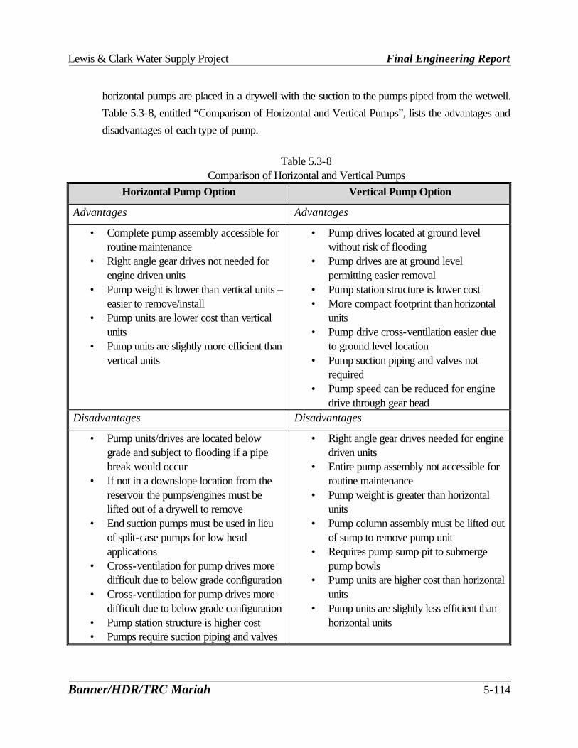
Lewis & Clark Water Supply Project Final Engineering Report
Banner/HDR/TRC Mariah 5-114
horizontal pumps are placed in a drywell with the suction to the pumps piped from the wetwell. Table 5.3-8, entitled “Comparison of Horizontal and Vertical Pumps”, lists the advantages and disadvantages of each type of pump.
Table 5.3-8 Comparison of Horizontal and Vertical Pumps
Horizontal Pump Option Vertical Pump Option
Advantages Advantages
• Complete pump assembly accessible for routine maintenance
• Right angle gear drives not needed for engine driven units
• Pump weight is lower than vertical units – easier to remove/install
• Pump units are lower cost than vertical units
• Pump units are slightly more efficient than vertical units
• Pump drives located at ground level without risk of flooding
• Pump drives are at ground level permitting easier removal
• Pump station structure is lower cost • More compact footprint than horizontal
units • Pump drive cross-ventilation easier due
to ground level location • Pump suction piping and valves not
required • Pump speed can be reduced for engine
drive through gear head Disadvantages Disadvantages
• Pump units/drives are located below grade and subject to flooding if a pipe break would occur
• If not in a downslope location from the reservoir the pumps/engines must be lifted out of a drywell to remove
• End suction pumps must be used in lieu of split-case pumps for low head applications
• Cross-ventilation for pump drives more difficult due to below grade configuration
• Cross-ventilation for pump drives more difficult due to below grade configuration
• Pump station structure is higher cost • Pumps require suction piping and valves
• Right angle gear drives needed for engine driven units
• Entire pump assembly not accessible for routine maintenance
• Pump weight is greater than horizontal units
• Pump column assembly must be lifted out of sump to remove pump unit
• Requires pump sump pit to submerge pump bowls
• Pump units are higher cost than horizontal units
• Pump units are slightly less efficient than horizontal units
Lewis & Clark Water Supply Project Final Engineering Report
Banner/HDR/TRC Mariah 5-115
Based on the comparison of horizontal and vertical pumps, the recommendation is made that horizontal pumps be used for the filter backwash and high service pump. This type of pump is more efficient and less expensive than a vertical unit. Also, the horizontal pump is much easier to maintain and it can be direct coupled to an engine without the use of right-angle gear drivers. 5.3.10.5. Type of Pump Drive Two types of pump drivers can be used for the backwash and high service pumps; electric motor and diesel engine driven. The drives must consider normal operating conditions as well as capabilities for emergency standby operation during power losses. There are advantages and disadvantages to each type of drive as shown in Table 5.3-9, entitled “Comparison of Direct Engine Driven and Electric Motor Driven Pumps”. Based on the advantages and disadvantages listed in Table 5.3-9, constant speed electric motor driven pumps will be used. A standby generator will be provided to power the backwash pump and high service pumps during an electrical outage. 5.3.10.6. Filter Backwash Pumps Section 5.3.4 developed the filter backwash rate and volume of water required for the filters. Each filter will have two cells. The cells will be backwashed consecutively to minimize the size of the pumps and piping. The backwash rate for each filter cell is a maximum 7,600 gpm. Two backwash pumps will be provided with one pump serving as a standby. Each pump will have a capacity of 7,600 gpm. Refer to Table 5.3-10, entitled “Recommended Pumps for Pump Station.

Lewis & Clark Water Supply Project Final Engineering Report
Banner/HDR/TRC Mariah 5-116
Table 5.3-9 Comparison of Direct Engine Driven and
Electric Motor Driven Pumps Direct Engine Driven Option Electric Motor Drive Option
Advantages Advantages
• Pump speed is variable • Engine drive can be specifically
matched to pump bhp to optimize operation
• Electrical switchgear/MCC complexity and cost reduced
• Overall pump drive operating efficiencies are higher than generator operated pumps
• Pumps have standby capability if electrical power fails
• Overall operating cost for diesel is less than for electric motors
• Engine generators for standby can be isolated from the pump room to control noise and cooling requirements
• Any pump can be selected to operate with the emergency generator
• All pumps operable from primary electrical power supply
• Right angle gear drives not required for vertical pump units
• Engine generators can be located at ground level for pit level centrifugal pumps
• Low rpm centrifugal pumps can be easily matched with generators
Direct Engine Driven Option Electric Motor Drive Option
Disadvantages Disadvantages
• Requires right angle gear drives on vertical pumps
• Engines must be located in pit level for horizontal pumps
• Low rpm centrifugal pumps requires oversized engine drives
• Each engine drive can only be used for operating one pump
• Pumps with engine drives not operable from electrical power source, unless dual drive used
• Engines cannot be isolated from the pump room creating noise and room cooling problems
• Engine requires more routine maintenance than electric motor drive
• Pump speed not variable unless VFD used • Overall pump drive operating efficiencies
are lower due to generator/motor losses • Automatic transfer switches required to
engage generators for emergency standby • Emergency engine generator must be
oversized to operate VFD’s • Total construction cost is higher due to
providing dual electrical systems
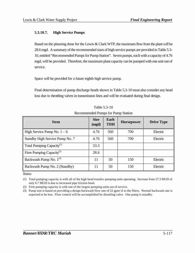
Lewis & Clark Water Supply Project Final Engineering Report
Banner/HDR/TRC Mariah 5-117
5.3.10.7. High Service Pumps Based on the planning done for the Lewis & Clark WTP, the maximum flow from the plant will be 28.6 mgd. A summary of the recommended sizes of high service pumps are provided in Table 5.3-10, entitled “Recommended Pumps for Pump Station”. Seven pumps, each with a capacity of 4.76 mgd, will be provided. Therefore, the maximum plant capacity can be pumped with one unit out of service. Space will be provided for a future eighth high service pump. Final determination of pump discharge heads shown in Table 5.3-10 must also consider any head loss due to throttling valves in transmission lines and will be evaluated during final design.
Table 5.3-10 Recommended Pumps for Pump Station
Item Size
(mgd) Each TDH
Horsepower Drive Type
High Service Pump No. 1 – 6 4.76 560 700 Electric
Standby High Service Pump No. 7 4.76 560 700 Electric
Total Pumping Capacity(1) 33.3
Firm Pumping Capacity(2) 28.6
Backwash Pump No. 1(3) 11 50 150 Electric
Backwash Pump No. 2 (Standby) 11 50 150 Electric
Notes:
(1) Total pumping capacity is with all of the high head transfer pumping units operating. Increase from 27.3 MGD of only 6.7 MGD is due to increased pipe friction head.
(2) Firm pumping capacity is with one of the largest pumping units out of service. (3) Pump size is based on providing a design backwash flow rate of 22 gpm/ sf to the filters. Normal backwash rate is
expected to be less. Flow control will be accomplished by throttling valve. One pump is standby.

Lewis & Clark Water Supply Project Final Engineering Report
Banner/HDR/TRC Mariah 5-118
5.3.10.8. Summary Key elements of the pump station and clearwell are:
? 3.0 million gallon clearwell separated into two cells ? Clearwell will be baffled for disinfection ? Clearwell size 142 ft x 142 ft x 18 ft water depth ? Horizontal pump arrangement ? Electric drives for all pumps ? Standby generator(s) provided for emergency power ? Firm pumping capacity of high service pumps is 28.6 mgd
5.3.11. Standby Power
Loss of primary power can occur as a result of thunderstorms, ice storms, other weather-related events and electrical system disruptions. Under emergency power conditions, commercial electrical energy is not available, however, the water treatment facilities must be able to provided treated water at a rate of 22 to 23 mgd, the average daily flow. To meet these requirements a standby generator(s) will be required to operate critical processes. Table 5.3-11 summarizes the major electrical loads that will require standby power.
Table 5.3-11
Estimated Power Loads
Equipment Description Number Horsepower Total
Horsepower Standby Horsepower
Required Softening Basins 3 40 120 120 Sludge Wasting Pumps 2 25 50 25 Backwash Water Pumps 2 150 300 150 Air Scour 2 50 100 50 Chemical Feed Systems (all) 1 100 100 80 High Service Pumping 7 700 4,900 3,500 Thickener Mechanism 1 10 10 0 Miscellaneous Loads 1 1 800 920 460 TOTALS 6,500 4,385 Note: (1) Miscellaneous loads estimated based on high service pumping accounting for approximately 75% of the overall
load.
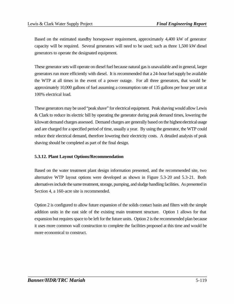
Lewis & Clark Water Supply Project Final Engineering Report
Banner/HDR/TRC Mariah 5-119
Based on the estimated standby horsepower requirement, approximately 4,400 kW of generator capacity will be required. Several generators will need to be used; such as three 1,500 kW diesel generators to operate the designated equipment. These generator sets will operate on diesel fuel because natural gas is unavailable and in general, larger generators run more efficiently with diesel. It is recommended that a 24-hour fuel supply be available the WTP at all times in the event of a power outage. For all three generators, that would be approximately 10,000 gallons of fuel assuming a consumption rate of 135 gallons per hour per unit at 100% electrical load. These generators may be used “peak shave” for electrical equipment. Peak shaving would allow Lewis & Clark to reduce its electric bill by operating the generator during peak demand times, lowering the kilowatt demand charges assessed. Demand charges are generally based on the highest electrical usage and are charged for a specified period of time, usually a year. By using the generator, the WTP could reduce their electrical demand, therefore lowering their electricity costs. A detailed analysis of peak shaving should be completed as part of the final design.
5.3.12. Plant Layout Options/Recommendation Based on the water treatment plant design information presented, and the recommended site, two alternative WTP layout options were developed as shown in Figure 5.3-20 and 5.3-21. Both alternatives include the same treatment, storage, pumping, and sludge handling facilities. As presented in Section 4, a 160-acre site is recommended. Option 2 is configured to allow future expansion of the solids contact basin and filters with the simple addition units in the east side of the existing main treatment structure. Option 1 allows for that expansion but requires space to be left for the future units. Option 2 is the recommended plan because it uses more common wall construction to complete the facilities proposed at this time and would be more economical to construct.

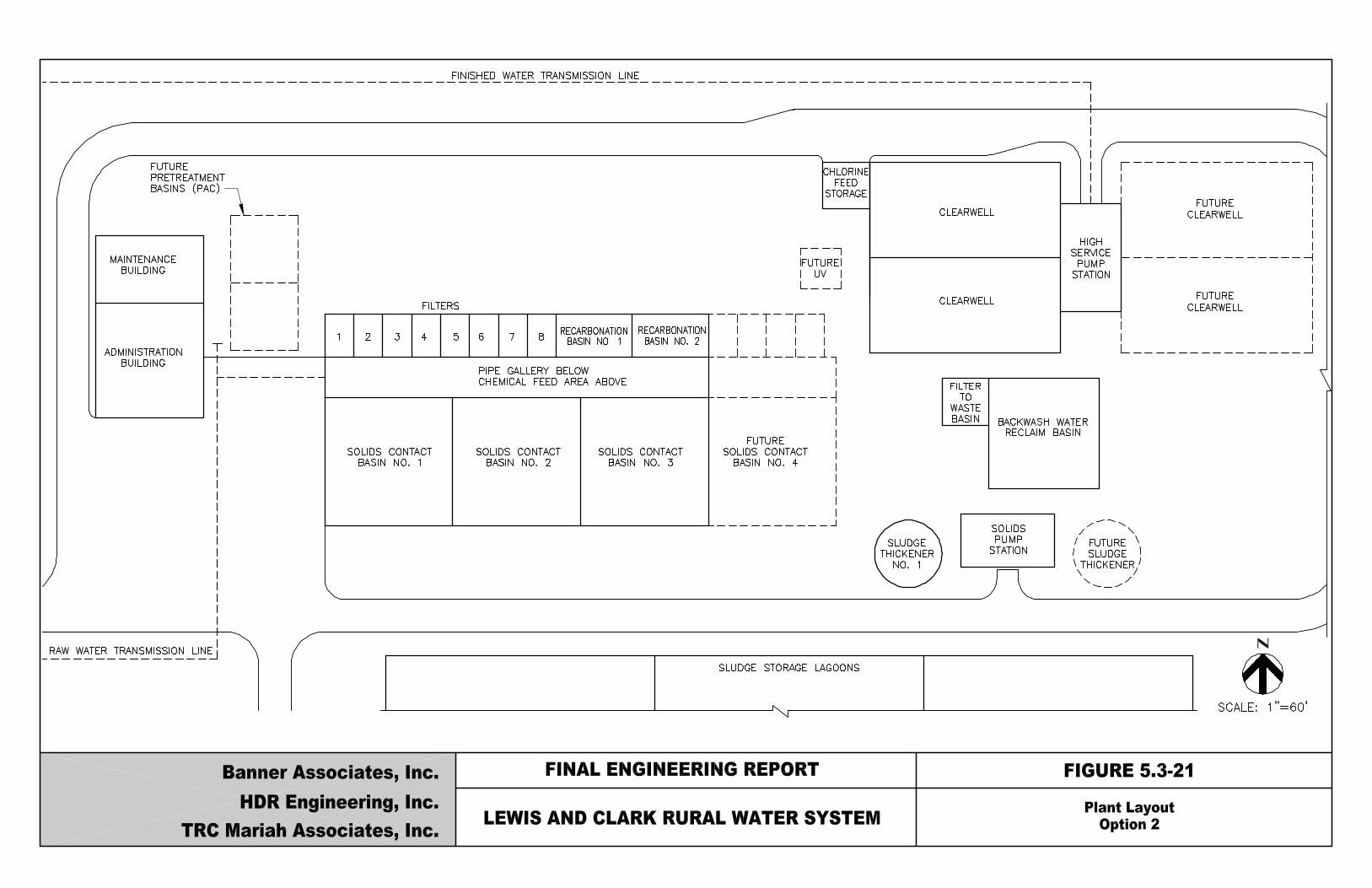
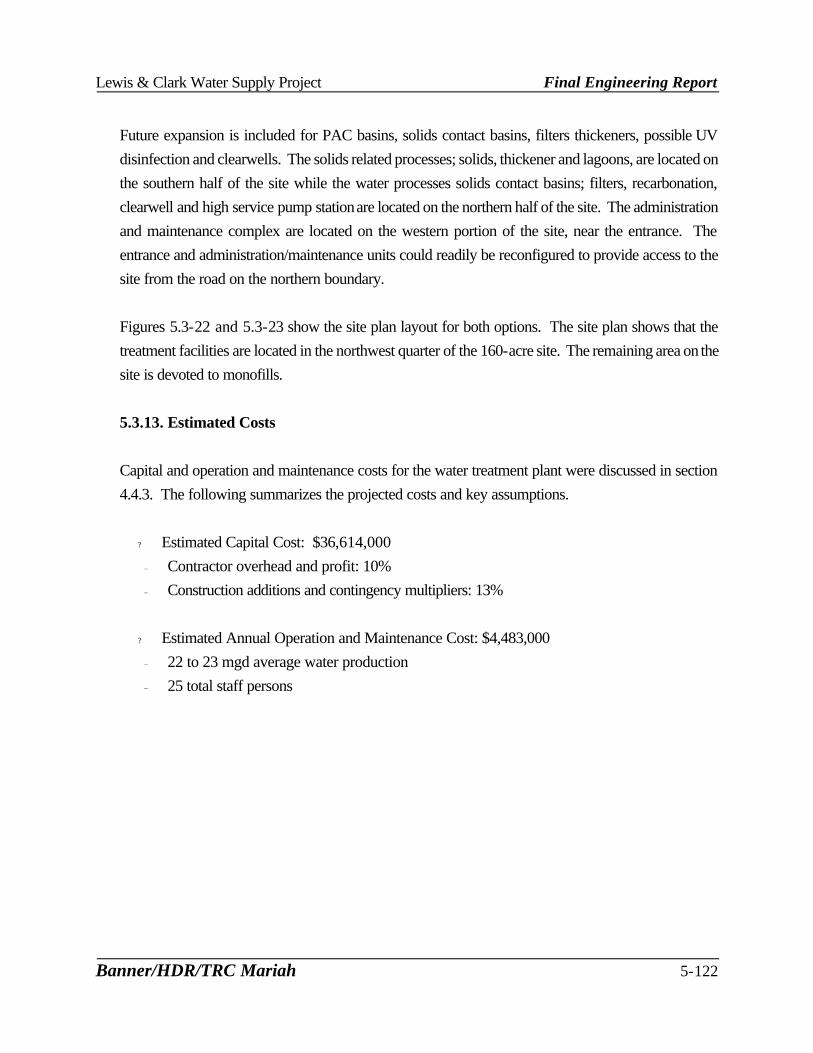
Lewis & Clark Water Supply Project Final Engineering Report
Banner/HDR/TRC Mariah 5-122
Future expansion is included for PAC basins, solids contact basins, filters thickeners, possible UV disinfection and clearwells. The solids related processes; solids, thickener and lagoons, are located on the southern half of the site while the water processes solids contact basins; filters, recarbonation, clearwell and high service pump station are located on the northern half of the site. The administration and maintenance complex are located on the western portion of the site, near the entrance. The entrance and administration/maintenance units could readily be reconfigured to provide access to the site from the road on the northern boundary. Figures 5.3-22 and 5.3-23 show the site plan layout for both options. The site plan shows that the treatment facilities are located in the northwest quarter of the 160-acre site. The remaining area on the site is devoted to monofills. 5.3.13. Estimated Costs
Capital and operation and maintenance costs for the water treatment plant were discussed in section 4.4.3. The following summarizes the projected costs and key assumptions.
? Estimated Capital Cost: $36,614,000 Contractor overhead and profit: 10% Construction additions and contingency multipliers: 13%
? Estimated Annual Operation and Maintenance Cost: $4,483,000 22 to 23 mgd average water production 25 total staff persons