Embed Size (px)
DESCRIPTION
Wireless Interfaces:- • Bridges one Gateway and Node on the same radio frequency band • Provides plug-and-play installation with direct I/O mapping between Gateway and Node • Offers discrete and analog I/O in the same unit • Provides built-in signal strength LED indicator WIRELESS DX80 DX99 DX70. Photoelectrics Sensors, Fiber Optic Sensors, Special Purpose Sensors, Measurement Inspection Sensors, Vision Wireless Indicators.
Citation preview

WIRELESS
DX80
DX99
DX70
More information online at bannerengineering.com 397
PhotoelectricsSensors
Fiber OpticSensors
Special PurposeSensors
Measurement & Inspection Sensors
Vision
Wireless
Indicators
Safety Light Screens
Safety Laser Scanners
Fiber OpticSafety Systems
Safety Controllers & Modules
Safety Two-Hand Control Modules
Safety Interlock Switches
Emergency Stop Devices
WIRELESS SENSOR NETWORKS
MultiHop RadioDX80 page 399• Selectable power levels up to 1 watt
transmit power; license-free operation up to 4 watt EIRP, with a high-gain antenna, in the U.S. and Canada for 900 MHz
• FlexPower power input options allow for +10 to 30V dc, solar or battery power sources
Point-to-MultipointDX80 page 400• Includes a Gateway and one or more
Nodes that operate on the same radio frequency band
• Accommodates any combination of Nodes and FlexPower™ Nodes
• Offers discrete, analog & discrete, temperature and M-GAGE™ Nodes
• Gateways directly connect to Modbus RTU, EtherNet/IP, Modbus TCP/IP and other industrial protocols
Intrinsically Safe DX99 page 408• Certified for operation in Class I Div 1
and ATEX Zone 0 locations• Powers all radio communications and
an external sensing device• Offers a choice of installation brackets
and antenna feed throughs
Point-to-Point DX70 page 410• Bridges one Gateway and Node on the
same radio frequency band• Provides plug-and-play installation
with direct I/O mapping between Gateway and Node
• Offers discrete and analog I/O in the same unit
• Provides built-in signal strength LED indicator
Accessories page 412• A wide selection of power supplies for
Gateways, Nodes and sensors• Modbus RTU remote I/O for
expanding Gateway I/O capacity• A complete selection of cordsets for
easy hookup• Antennas, cables and accessories for
virtually every location challenge
DX70DX99DX80MultiHop

WIR
ELES
S DX80 DX99 DX70
More information online at bannerengineering.com398
3. SureCross™ Wireless Family FeaturesMultiHop Radio
IP67DX80 IP67
DX80..C IP20 CID2
DX80 IP67
DX80..C IP20 CID2
DX99IP67 CID1
DX70IP67
FlexPower: 10 to 30V dc Battery Solar
GatewaysFlexPower: 10 to 30V dc
Solar
NodesFlexPower: 10 to 30V dc
Battery Solar
Intrinsically Safe NodesFlexPower: Battery
Power: 10 to 30V dc
Data: RS-232 RS-485 Ethernet (900 MHz only)
I/O: Discrete Analog
Networks: Modbus RTU Master & SlaveEtherNet/IPModbus TCP/IP
I/O: Discrete Analog Counter Serial — T30 Ultrasonic
M12 Temp & Relative Humidity QS30 Photoelectric SDI-12
Temp — Thermocouple RTD
I/O: Discrete Analog
Temp — Thermocouple RTD
I/O: Discrete Analog
1. Radio and Antenna Options Banner recommends conducting a site survey to verify range in your location.
2.4 GHz — Global wireless standard900 MHz — recommended for use in North America
Wireless SolutionsSpecify Your Wireless Solution in 3 Simple Steps
1. Radio and Antenna Options
2. Wireless Network Architectures
3. SureCross Wireless family features
DX70 Point-to-Point MultiHop Wireless NetworkDX80 and DX99Point-to-Multipoint
2. Wireless Network Architectures
Antenna Options Internal External High-gain remote

WIRELESS
DX80
DX99
DX70
More information online at bannerengineering.com 399
PhotoelectricsSensors
Fiber OpticSensors
Special PurposeSensors
Measurement & Inspection Sensors
Vision
Wireless
Indicators
Safety Light Screens
Safety Laser Scanners
Fiber OpticSafety Systems
Safety Controllers & Modules
Safety Two-Hand Control Modules
Safety Interlock Switches
Emergency Stop Devices
ACCESSORIES
page412
SureCross™ DX80 MultiHopWireless Network• Selectable power levels up to 1 watt transmit power; license-free operation up to
4 watt EIRP, with a high-gain antenna, in the U.S. and Canada for 900 MHz
• FlexPower power input options allow for +10 to 30V dc, solar or battery power
• Serial communication style (RS-232 or RS-485) is user selectable
• Multiple hops allow for an extended range
• Message routing improves link performance
• SureCross architecture creates self-forming and self-healing wireless networks
• DIP switches select operational modes: master, repeater or slave
• Built-in site survey mode enables rapid assessment of a location’s RF transmission properties by one person; hands-free operation and rapid display updates enable efficient antenna placement optimization
• FHSS radios operate and synchronize automatically; no user setup is required; Selectable network IDs reduce interference from collocated networks
• Banner is constantly working on new models with I/O variations, contact factory for the latest model information
DX80 Data RadiosDescription Frequency Transmit Power Models*
MultiHop Radio900 MHz DIP switch selectable up to 1 Watt DX80DR9M-H
2.4 GHz 150 mW EIRP DX80DR2M-H
* Banner is constantly working on new models with I/O variations. Contact factory for the latest model information.
SureCross™ Ethernet RadioDescription Frequency Transmit Power Models*
Ethernet Radio 900 MHz 150 mW DXER9
DX85 Modbus RTU Remote I/OUsed to expand I/O capacity when connected to a Data Radio or Gateway (see page 406)
MultiHop Wireless Network
Ethernet Data Radio
216 mm
97 mm
59 mm
MultiHop
80.3 mm
42 mm
65 mm80.8 mm
Data Radios
DX80 Data Radio DX80 SpecificationsVisit bannerengineering.com for more information.

WIR
ELES
S DX80 DX99 DX70
More information online at bannerengineering.com400
ACCESSORIES
page412
SureCross™
DX80 Point-to-MultipointWireless I/O Network• An industrial wireless I/O network that can operate in extreme environments
while eliminating the need for costly wiring runs• A basic network consists of a Gateway system controller and one or more
Nodes that monitor and/or control I/O in remote locations• Nodes are easily deployed throughout a facility for gathering data to be
concentrated at the Gateway• Bi-directional communication between the Gateway and Node(s), including
fully acknowledged data transmission• Frequency Hopping Spread Spectrum (FHSS) technology and Time Division
Multiple Access (TDMA) control architecture combine to ensure reliable data delivery within the unlicensed Industrial, Scientific and Medical (ISM) bands
• FlexPower™ options allow for +10-30V dc, solar and battery power sources• 900 MHz and 2.4 GHz models accommodate worldwide communication standards• Rugged IP67/NEMA 6 design enabling simple plug-and-play installation• Installation is fast and easy with flexible mounting and power options
DX80 Gateways DX80 Nodes• Gateways are the master of Banner’s SureCross
Wireless Network• Modbus 485 communication capability is integrated
into every Gateway• Gateway models are available with discrete, analog
and a mix of both I/O types• IP20 housing option is certified for Class I Div 2 areas
• The Node collects the data and wirelessly transmits it to the Gateway
• Nodes may be powered by either 10 to 30V dc battery or solar power options
• Models are available in a variety of input/output options
• IP20 housing option is certified for Class I Div 2 areas
127.0 mm
60.0 mm
80.8 mm
65 mm
ONLINE
AUTOCAD, STEP, IGES & PDF
DX80 Gateways and Node
DX80 and DX99Point-to-Multipoint
DX80 Node
127.0 mm
60.0 mm
80.8 mm
65 mm
DX80 Gateway
DX85 Modbus RTU Remote I/OUsed to expand I/O capacity when connected to a Data Radio or Gateway (see page 406)

WIRELESS
DX80
DX99
DX70
More information online at bannerengineering.com 401
PhotoelectricsSensors
Fiber OpticSensors
Special PurposeSensors
Measurement & Inspection Sensors
Vision
Wireless
Indicators
Safety Light Screens
Safety Laser Scanners
Fiber OpticSafety Systems
Safety Controllers & Modules
Safety Two-Hand Control Modules
Safety Interlock Switches
Emergency Stop Devices
DX80 EtherNet/IP and Modbus TCP Gateways
Frequency I/O Models
DX80P2T6S
DX80P9T6S
DX83
900 MHz
DX80 GatewayPro Modbus/TCP to EtherNet/IP protocol converter
DX80P9T6S
2.4 GHz DX80P2T6S
900 MHzDX80 GatewayPro (Modbus/TCP) with advanced web-based
configuration capabilities
DX80P9A6S
2.4 GHz DX80P2A6S
No Radio
Protocol Conversion: Modbus RTU to Modbus TCP/IP or EtherNet/IP DX83T
Advanced user configuration model DX83A
ACCESSORIES
page412
DX80 Modbus RTU Gateways, 10–30V dc
Frequency Base I/O Models*
DX80..CIP20 ExternalTerminal StripsCID2 certified
DX80 IP67 900 MHzIP67
Discrete: Six selectable inputs, six PNP outputs
DX80G9M6S6P6
IP20 DX80G9M6S6P6C
2.4 GHzIP67 DX80G2M6S6P6
IP20 DX80G2M6S6P6C
900 MHzIP67
Discrete: Six selectable inputs, six NPN outputs
DX80G9M6S6N6
IP20 DX80G9M6S6N6C
2.4 GHzIP67 DX80G2M6S6N6
IP20 DX80G2M6S6N6C
900 MHzIP67
Analog: Four inputs, four 0-20 mA outputs
DX80G9M6S0P0M4M4
IP20 DX80G9M6S0P0M4M4C
2.4 GHzIP67 DX80G2M6S0P0M4M4
IP20 DX80G2M6S0P0M4M4C
DX80..CIP20 ExternalTerminal StripsCID2 certified
DX80 IP67
900 MHzIP67
Analog: Four inputs, four 0-10V outputs
DX80G9M6S0P0V4V4
IP20 DX80G9M6S0P0V4V4C
2.4 GHzIP67 DX80G2M6S0P0V4V4
IP20 DX80G2M6S0P0V4V4C
900 MHzIP67
Discrete: Four selectable inputs, four PNP outputsAnalog: Two inputs, two 0-20 mA outputs
DX80G9M6S4P4M2M2
IP20 DX80G9M6S4P4M2M2C
2.4 GHzIP67 DX80G2M6S4P4M2M2
IP20 DX80G2M6S4P4M2M2C
900 MHzIP67
Discrete: Four selectable inputs, four PNP outputsAnalog: Two inputs, two 0-10V outputs
DX80G9M6S4P4V2V2
IP20 DX80G9M6S4P4V2V2C
2.4 GHzIP67 DX80G2M6S4P4V2V2
IP20 DX80G2M6S4P4V2V2C
900 MHzIP67
Discrete: Eight selectable inputs, four PNP outputs (When your wireless network does not include a host system, eight input/four output Gateway must be mapped to the four input/eight output node.)
DX80G9M6S8P4
IP20 DX80G9M6S8P4C
2.4 GHzIP67 DX80G2M6S8P4
IP20 DX80G2M6S8P4C
900 MHzIP67
Discrete: Four selectable inputs, eight PNP outputs (When your wireless network does not include a host system, the four input/eight output Gateway must be mapped to the eight input/four output node.)
DX80G9M6S4P8
IP20 DX80G9M6S4P8C
2.4 GHzIP67 DX80G2M6S4P8
IP20 DX80G2M6S4P8C
* To order the internal antenna models, replace the S as the 9th digit with a W. Internal antennas require an additional week for manufacture and shipping. For example, DX80G9M6S0P0V4V4 is the external antenna model and DX80G9M6W0P0V4V4 is the internal antenna model.

WIR
ELES
S DX80 DX99 DX70
More information online at bannerengineering.com402
DX80 Nodes, 10-30V dc—Analog and Discrete
Frequency Base I/O Models*
DX80 Node IP67
DX80..CIP20 ExternalTerminal StripsCID2 certified
900 MHz
IP67
Discrete: Four selectable inputs, four PNP outputsAnalog: Two inputs, two outputs (0-20 mA)
DX80N9X6S4P4M2M2
IP20 DX80N9X6S4P4M2M2C
2.4 GHz
IP67 DX80N2X6S4P4M2M2
IP20 DX80N2X6S4P4M2M2C
900 MHz
IP67
Discrete: Four selectable inputs, four PNP outputsAnalog: Two inputs, two outputs (0-10V)
DX80N9X6S4P4V2V2
IP20 DX80N9X6S4P4V2V2C
2.4 GHz
IP67 DX80N2X6S4P4V2V2
IP20 DX80N2X6S4P4V2V2C
DX80 Nodes, FlexPower—Analog and Discrete
Frequency Base I/O Models*
QT50ULBQ6-75390
DX80 Node
DX81
900 MHzIP67
Discrete: Two selectable inputs, two NMOS sinking outputsAnalog: Two inputs (0-20 mA, depending on configuration)Switched Power Outputs
DX80N9X2S2N2M2
IP20 DX80N9X2S2N2M2C
2.4 GHzIP67 DX80N2X2S2N2M2
IP20 DX80N2X2S2N2M2C
900 MHzIP67
Discrete: Two selectable inputs, two NMOS sinking outputsAnalog: Two 0-10V inputs (depending on configuration)Switched Power Outputs
DX80N9X2S2N2V2
IP20 DX80N9X2S2N2V2C
2.4 GHzIP67 DX80N2X2S2N2V2
IP20 DX80N2X2S2N2V2C
* All Nodes on this page are available with internal antennas. To order the internal antenna models, replace the S as the 9th digit with a W. Internal antennas require an additional week for manufacture and shipping. For example, DX80N9X2S2N2M2 is the model number for the external antenna device and DX80N9X2W2N2M2 is the internal antenna device. FlexPower Nodes can be powered using 10-30V dc, battery or solar power options. Power supplies are sold separately (see page 412).
ACCESSORIES
page412
DX80 Gateways, FlexPower
Frequency I/O Antenna Models*
DX80G9M2S
900 MHz
The FlexPower Gateway with a serial interface is designed to be powered by 10-30V dc, a battery pack or the solar powered system with rechargeable batteries. Class I Div 2 certified.
DX80G9M2S
2.4 GHz DX80G2M2S
* FlexPower Gateways are available with an external antenna only. FlexPower Gateways can be powered using 10-30V dc, Battery or solar power supply options. Power supplies are sold separately. (see page 412).
Moreon next page

WIRELESS
DX80
DX99
DX70
More information online at bannerengineering.com 403
PhotoelectricsSensors
Fiber OpticSensors
Special PurposeSensors
Measurement & Inspection Sensors
Vision
Wireless
Indicators
Safety Light Screens
Safety Laser Scanners
Fiber OpticSafety Systems
Safety Controllers & Modules
Safety Two-Hand Control Modules
Safety Interlock Switches
Emergency Stop Devices
ACCESSORIES
page412
DX80 Nodes, 10-30V dc—Discrete
Frequency Base I/O Models*
DX80 Node IP67
DX80..CIP20 ExternalTerminal StripsCID2 certified
900 MHzIP67
Discrete: Six selectable inputs, six PNP outputs
DX80N9X6S6P6
IP20 DX80N9X6S6P6C
2.4 GHzIP67 DX80N2X6S6P6
IP20 DX80N2X6S6P6C
900 MHzIP67
Discrete: Six selectable inputs, six NPN outputs
DX80N9X6S6N6
IP20 DX80N9X6S6N6C
2.4 GHzIP67 DX80N2X6S6N6
IP20 DX80N2X6S6N6C
900 MHzIP67
Discrete: Eight selectable inputs, four PNP outputs (When your wireless network does not include a host system, the eight input/four output node must be mapped to the four input/eight output Gateway.)
DX80N9X6S8P4
IP20 DX80N9X6S8P4C
2.4 GHzIP67 DX80N2X6S8P4
IP20 DX80N2X6S8P4C
900 MHzIP67
Discrete: Four selectable inputs, eight PNP outputs (When your wireless network does not include a host system, the four input/eight output node must be mapped to the eight input/four output Gateway.)
DX80N9X6S4P8
IP20 DX80N9X6S4P8C
2.4 GHzIP67 DX80N2X6S4P8
IP20 DX80N2X6S4P8C
* All Nodes on this page are available with internal antennas. To order the internal antenna models, replace the S as the 9th digit with a W. Internal antennas require an additional week for manufacture and shipping. For example, DX80N9X1S2N1M1 is the model number for the external antenna device and DX80N9X1W2N1M1 is the internal antenna device.
FlexPower™ Node with Switched Power Outputs
Frequency Base I/O Models*
900 MHz
IP67
Discrete: Two selectable inputs, one NMOS sinking outputAnalog: One 0-20 mA inputSwitched Power Outputs
Battery integrated into the housing
DX80N9X1S2N1M1
2.4 GHz DX80N2X1S2N1M1
900 MHzDiscrete: Two selectable inputs, one NMOS sinking outputAnalog: One 0-10V inputSwitched Power Outputs
Battery integrated into the housing
DX80N9X1S2N1V1
2.4 GHz DX80N2X1S2N1V1

WIR
ELES
S DX80 DX99 DX70
More information online at bannerengineering.com404
DX80 Nodes, 10-30V dc—Analog
Frequency Base I/O Models*
DX80 Node IP67
DX80 Node IP20(C1D2 certified)
900 MHz
IP67
Analog: Four 0-20 mA inputs, four 0-20 mA outputs
DX80N9X6S0P0M4M4
IP20 DX80N9X6S0P0M4M4C
2.4 GHz
IP67 DX80N2X6S0P0M4M4
IP20 DX80N2X6S0P0M4M4C
900 MHz
IP67
Analog: Four 0-10V inputs, four 0-10V outputs
DX80N9X6S0P0V4V4
IP20 DX80N9X6S0P0V4V4C
2.4 GHz
IP67 DX80N2X6S0P0V4V4
IP20 DX80N2X6S0P0V4V4C
Counter DX80 Nodes, FlexPower
Frequency Base I/O Counter Input Models*
DX80N9X1S2A1
900 MHz
IP67
Discrete: Two selectable inputs, two NMOS sinking outputs
Counter: Two selectable inputs
User selectable10 kHz event counter(s)25 kHz frequency counter(s)
DX80N9X2S4A2
IP20 DX80N9X2S4A2C
2.4 GHz
IP67 DX80N2X2S4A2
IP20 DX80N2X2S4A2C
900 MHz
IP67
Discrete: One selectable inputs, one NMOS sinking output
Counter: One selectable input
Battery integrated into the housing
DX80N9X1S2A1
2.4 GHz DX80N2X1S2A1
* To order the internal antenna models, replace the S as the 9th digit with a W. Internal antennas require an additional week for manufacture and shipping. For example, DX80N9X2S4A2 is the model number for the external antenna device and DX80N9X2W4A2 is the internal antenna device. Models with batteries integrated into the housing are so noted. All other FlexPower models may powered using 10-30V dc, battery or solar power options. Power supplies are sold separately. (see page 412).
ACCESSORIES
page412

WIRELESS
DX80
DX99
DX70
More information online at bannerengineering.com 405
PhotoelectricsSensors
Fiber OpticSensors
Special PurposeSensors
Measurement & Inspection Sensors
Vision
Wireless
Indicators
Safety Light Screens
Safety Laser Scanners
Fiber OpticSafety Systems
Safety Controllers & Modules
Safety Two-Hand Control Modules
Safety Interlock Switches
Emergency Stop Devices
ACCESSORIES
page412
Solar DX80 Nodes
Frequency I/O Models†
DX80N9X2S-CS1 and BWA-SOLAR-001
900 MHzDiscrete Inputs: Two selectableSwitch Power: One continuous Analog Inputs: Two 0–20 mAThermistor: OneBattery Status: OneDiscrete Output: One NMOS sinking
DX80N9X2S-CS1
2.4 GHz DX80N2X2S-CS1
† Required FlexPower solar supply is sold separately (see page 412).
Temperature DX80 Nodes, FlexPower
Frequency Base I/O Models*
DX80N2X2S2N2TC
900 MHz
IP67
Thermocouple: Three inputs, one thermistor CJC inputDiscrete: Two selectable inputs, two NMOS sinking outputs
DX80N9X2S2N2T
IP20 DX80N9X2S2N2TC
2.4 GHz
IP67 DX80N2X2S2N2T
IP20 DX80N2X2S2N2TC
900 MHz
IP67
RTD: Four three-wire inputs
DX80N9X2S0P0R
IP20 DX80N9X2S0P0RC
2.4 GHz
IP67 DX80N2X2S0P0R
IP20 DX80N2X2S0P0RC
Serial DX80 Nodes, FlexPower
Frequency Base I/O Models*
DX80N9X2S2SDX81
900 MHz
IP67
Single one-wire serial port to handle
up to two serial sensors
DX80N9X2S2S
2.4 GHz DX80N2X2S2S
900 MHz Single one-wire serial port to handle
one serial sensor
Battery integrated into the housing
DX80N9X1S1S
2.4 GHz DX80N2X1S1S
* To order the internal antenna models, replace the S in the 9th digit with a W. Internal antennas require an additional week for manufacture and shipping. For example, DX80N9X2S2S is the model number for the external antenna device and DX80N9X2W2S is the internal antenna device.
Models with batteries integrated into the housing are so noted. All other FlexPower Nodes may be powered using 10-30V dc, battery or solar power options. Power supplies are sold separately. (see page 412).
FlexSensor Serial Models
T30UFDNCQ Discrete, ultrasonic, 3 m range
M12FTH1QTemperature and relative humidity sensor ±2%
M12FTH2QTemperature and relative humidity sensor ±3.5%(Both offer NIST traceability)
QS30WEQ (emitter) QS30WRQ (receiver)Photoelectric pair up to 100' range

WIR
ELES
S DX80 DX99 DX70
More information online at bannerengineering.com406
DX85 Modbus RTU Remote I/O
Base I/O Models
DX85..C
DX85
IP67Discrete: Six PNP inputs, six PNP outputs
DX85M6P6
IP20 DX85M6P6C
IP67Analog: Four inputs, four 0-20 mA outputs
DX85M0P0M4M4
IP20 DX85M0P0M4M4C
IP67Discrete: Four PNP inputs, four PNP outputsAnalog: Two inputs, two 0-20 mA outputs
DX85M4P4M2M2
IP20 DX85M4P4M2M2C
IP67 Discrete: Eight PNP inputs, four PNP outputs
(When your wireless network does not include a host system, the eight input/four output devices must be mapped to the four input/eight output devices.)
DX85M8P4
IP20 DX85M8P4C
IP67 Discrete: Four sourcing inputs, eight sourcing outputs
(When your wireless network does not include a host system, the four input/eight output devices must be mapped to the eight input/four output devices.)
DX85M4P8
IP20 DX85M4P8C
ACCESSORIES
page412
M-GAGE™ DX80 Nodes
Frequency Base Description Models†
DX80N2X1W0P0ZR
900 MHz
IP67M-GAGE sensor with an internal antenna and a battery integrated into an easy to embed Node housing
DX80N9X1W0P0ZR
2.4 GHz DX80N2X1W0P0ZR
† The M-GAGE Nodes are powered by a 3.6V lithium D cell integrated into the housing.
SureCross™ DX80 SpecificationsRadio
Range* 900 MHz: Up to 4.8 kilometers (3 miles); 2.4 GHz: Up to 3.2 kilometers (2 miles)
Transmit Power (150 mW radios) 900 MHz: 21 dBm Conducted; 2.4 GHz: 18 dBm Conducted, ≤ 20 dBm EIRP
Spread Spectrum Technology FHSS (Frequency Hopping Spread Spectrum)
Antenna Connector Ext. Reverse Polarity SMA, 50 Ohms
Antenna Max. Tightening Torque 0.45 N•m (4 in•lbf)
Link Timeout Gateway: Configurable, up to 2 minutes Node: Defined by Gateway
* With the standard 2 dB antenna. High-gain antennas are available, but the range depends on the environment and line of sight. To determine the range of your wireless network, perform a Site Survey.
Moreon next page

WIRELESS
DX80
DX99
DX70
More information online at bannerengineering.com 407
PhotoelectricsSensors
Fiber OpticSensors
Special PurposeSensors
Measurement & Inspection Sensors
Vision
Wireless
Indicators
Safety Light Screens
Safety Laser Scanners
Fiber OpticSafety Systems
Safety Controllers & Modules
Safety Two-Hand Control Modules
Safety Interlock Switches
Emergency Stop Devices
SureCross™ DX80 SpecificationsGeneral
Power* +10 to 30V dc (For European applications: +10 to 24V dc, ± 10%)FlexPower: +10 to 30V dc or 3.6 to 5.5V dc low power option (For European applications: +10 to 24V dc, ± 10% or 3.6 to 5.5V dc low power option)Integrated Battery models: 3.6V dc low power option from an internal battery
Power Consumption Less than 1.4 W (60 mA) at 24V dc
Mounting #10 or M5 (M5 hardware included)
M5 Fasteners Max. Tightening Torque
0.56 N•m (5 in•lbf)
Case Material Polycarbonate
Weight 0.26 kg (0.57 lb.)Integrated battery models: 0.30 kg (0.65 lbs)IP20 models: 0.23 kg (0.50 lbs)
Indicators Two LED, bi-color
Switches Two Push Buttons
Display Six Character LCD
Connection** 5-pin M12 Euro-style quick disconnect (QD cable is included with DX80 product)
External Cable Glands** Four PG-7 type, One 1/2 NPT type
Cable Glands Max. Tightening Torque**
0.56 N•m (5 in•lbf)
Gateway Communications
Interface 2-wire RS-485
Baud Rates 9.6k, 19.2k (default), or 38.4k
Data Format 8 data bits, no parity, 1 stop bit
Protocol Modbus RTU
Environmental
Environmental Rating Internal wiring terminals: IEC IP67; NEMA 6 External wiring terminals: IEC IP20; NEMA 1
Environmental Rating (external wiring terminals, in suitable enclosure)
External wiring block models: Class I, Division 2, Group A, B, C, DT4 −40 to +80° C
Operating Temperature Electronics: −40 to +85° C LCD: −20 to +80° C
Operating Humidity 95% max. relative (non-condensing)
Radiated Immunity 10 V/m, 80-2700 MHz (EN61000-6-2)
Shock and Vibration*** IEC 68-2-6 and IEC 68-2-7 Shock: 30g, 11 millisecond half sine wave, 18 shocks Vibration: 0.5 mm p-p, 10 to 60 Hz
Compliance, Radio
900 MHz Models FCC ID TGUDX80: This device complies with FCC Part 15, Subpart C, 15.247 IC: 7044A-DX8009
2.4 GHz Models FCC ID UE300DX80-2400: This device complies with FCC Part 15, Subpart C, 15.247 ETSI/EN: In accordance with EN 300 328: V1.7.1 (2006-05) IC: 7044A-DX8024
Certification (DX8x..C External Wiring Terminals and IP20 Housings)
Class I, Division 2, Groups A, B, C, D. Certificate: 1921239 Ex/AEx nA II T4
LCIE/ATEX Zone 2 (Group IIC). Certificate: LCIE 09 ATEX 1035 U II 3G Ex nA IIC
* For European applications, power the DX80 from a Limited Power Source as defined in EN 60950-1.** IP67 models only*** Operating the devices at the maximum operating conditions for extended periods can shorten the life of the device.
(cont’d)

WIR
ELES
S DX80 DX99 DX70
More information online at bannerengineering.com408
SureCross™ DX99Intrinsically Safe FlexPower™ Nodes• The DX99 is a state-of-the-art combination of wireless communication,
battery technology and intrinsically safe electronics
• All models are certified for operation in Class I Division 1 and ATEX Zone 0 locations
• Discrete, analog and temperature input types are available
• Battery power supply provides power for third-party 4-20 mA and NAMUR process sensors
• DX99 FlexPower Nodes are available in two different housing materials: metal and polycarbonate
• Banner is working on expanding the I/O options for our DX99 product line, visit bannerengineering.com for the most up to date models
DX99 Intrinsically Safe Nodes—Polycarbonate Housing
FrequencyBoost Power
Certifications I/OExternal
Antenna Models*
DX99N9X2S2N0M2X0A1
DX81H
900 MHz
10V
CSAClass I, Division 1, Groups A, B, C, DEx ia IIC AEx ia IIC T4
Discrete: Two selectable inputsAnalog: Two 0-20 mA inputs
DX99N9X2S2N0M2X0A1
2.4 GHz DX99N2X2S2N0M2X0A1
900 MHz Discrete: Two selectable inputsAnalog: Two 0-10V inputs
DX99N9X2S2N0V2X0A1
2.4 GHz DX99N2X2S2N0V2X0A1
900 MHz
18V
Discrete: Two selectable inputsAnalog: Two 0-20 mA inputs
DX99N9X2S2N0M2X0A2
2.4 GHz DX99N2X2S2N0M2X0A2
900 MHz Discrete: Two selectable inputsAnalog: Two 0-10V inputs
DX99N9X2S2N0V2X0A2
2.4 GHz DX99N2X2S2N0V2X0A2
900 MHz
—
Thermocouple: Three thermocouple inputs, one thermistor input
Discrete: Two NPN inputs
DX99N9X2S2N0T4X0A0
2.4 GHz DX99N2X2S2N0T4X0A0
900 MHzRTD: Four inputs
DX99N9X2S0N0R4X0A0
2.4 GHz DX99N2X2S0N0R4X0A0
* To order the internal antenna models, replace the S as the 9th digit with a W. Internal antennas require an additional week for manufacture and shipping. For example, DX99N9X2S2N0M2X0A1 is the model with the external antenna and DX99N9X2W2N0M2X0A1 is the internal antenna model. Required DX81H Battery supply is sold separately (see page 412).
65 mm
127 mm
60 mm
80.8 mm
ONLINE
AUTOCAD, STEP, IGES & PDF
206 mm
ø 110 mm
ACCESSORIES
page412
Banner offers a variety of mounting brackets and antenna feed throughs, visit www.bannerengineering.com for ordering information.

WIRELESS
DX80
DX99
DX70
More information online at bannerengineering.com 409
PhotoelectricsSensors
Fiber OpticSensors
Special PurposeSensors
Measurement & Inspection Sensors
Vision
Wireless
Indicators
Safety Light Screens
Safety Laser Scanners
Fiber OpticSafety Systems
Safety Controllers & Modules
Safety Two-Hand Control Modules
Safety Interlock Switches
Emergency Stop Devices
ACCESSORIES
page412
DX99 Intrinsically Safe Nodes—Metal Housing
FrequencyBoost Power
Certifications I/OExternal
Antenna Models*
DX99N9X1S2N0M2X0B1
900 MHz
10V
CSAClass I, Division 1, Groups A, B, C, D; Class II, Division 1, Groups E, F, G; Class III, Division 1;Ex ia IIC T4 AEx ia IIC T4
Discrete: Two inputsAnalog: Two 0-20 mA inputs
DX99N9X1S2N0M2X0B1
18V DX99N9X1S2N0M2X0B2
10V Discrete: Two inputsAnalog: Two 0-10V inputs
DX99N9X1S2N0V2X0B1
18V DX99N9X1S2N0V2X0B2
2.4 GHz
10V Discrete: Two inputsAnalog: Two 0-20 mA inputs
DX99N2X1S2N0M2X0B1
18V DX99N2X1S2N0M2X0B2
10V Discrete: Two inputsAnalog: Two 0-10V inputs
DX99N2X1S2N0V2X0B1
18V DX99N2X1S2N0V2X0B2
900 MHz—
Thermocouple: Three inputs, one thermistor input
Discrete: Two NPN inputs
DX99N9X1S2N0T4X0B0
2.4 GHz DX99N2X1S2N0T4X0B0
900 MHz— RTD: Four inputs
DX99N9X1S0N0R4X0B0
2.4 GHz DX99N2X1S0N0R4X0B0
* The metal housing models are only available with external antennas and are powered by a 3.6V D cell lithium battery integrated into the housing.
SureCross™ DX99 SpecificationsGeneral
Power FlexPower: 3.6 to 5.5V dc low power option DX99 FlexPower Polycarbonate Housing: 3.6V dc low power from the DX81H Battery Supply Modules
Power Consumption Application dependant
Mounting Polycarbonate Housing: #10 or M5 (M5 hardware included) Metal Housing: See data sheet for bracket options
M5 Fasteners Max. Tightening Torque
0.56 N•m (5 in•lbf)
Case Material and Weight Polycarbonate Housing: 0.26 kg (0.57 lb.) Metal Housing: 2.23 kg (4.9 lb.)
Indicators Two LED, bi-color
Switches Two Push Buttons
Display Six Character LCD
External Cable Glands Four PG-7 type, One 1/2 NPT type
Cable Glands Max. Tightening Torque
0.56 N•m (5 in•lbf)
Environmental
Environmental Rating Intrinsically safe, polycarbonate housing: IEC IP67, NEMA 4x Intrinsically safe, metal housing: IEC IP68
Operating Temperature −40 to +70° C
Operating Humidity 95% max. relative (non-condensing)
Radiated Immunity 10 V/m, 80-2700 MHz (EN61000-6-2)
Shock and Vibration IEC 68-2-6 and IEC 68-2-7 Shock: 30g, 11 millisecond half sine wave, 18 shocks Vibration: 0.5 mm p-p, 10 to 60 Hz
Compliance, Radio: See DX80
Certifications DX99, Intrinsically Safe, Polycarbonate Housing DX99, Intrinsically Safe, Metal Housing
Class I, Division 1, Groups A, B, C, D Ex ia IIC AEx ia IIC T4
LCIE/ATEX Zone 0 (Group IIC), Temperature Class T4 II 1 G Ex ia IIC T4
Class I, Division 1,Groups A, B, C, D; Class II, Division 1, Groups E, F, G; Class III, Division 1 Ex ia IIC T4 AEx ia IIC T4
LCIE/ATEX Zone 0 (Group IIC) and Zone 20 (Group II) II 1 GD Ex ia IIC T4 Ex iaD 20 Ta +82°C IP68

WIR
ELES
S DX80 DX99 DX70
More information online at bannerengineering.com410
ACCESSORIES
page412
DX70, 10-30V dcFrequency I/O Gateway Models* Node Models*
Node Gateway
900 MHzDiscrete: Four selectable inputs, four PNP outputsAnalog: Two selectable inputs, two 0-20 mA outputs
DX70G9X6S4P4M2M2 DX70N9X6S4P4M2M2
2.4 GHz DX70G2X6S4P4M2M2 DX70N2X6S4P4M2M2
900 MHz Gateway Discrete: Four selectable inputs, eight PNP outputs
Node Discrete: Eight selectable inputs, four PNP outputs
DX70G9X6S4P8 DX70N9X6S8P4
2.4 GHz DX70G2X6S4P8 DX70N2X6S8P4
* To order the internal antenna models, replace the S as the 9th digit with a W. Internal antennas require an additional week for manufacture and shipping. For example, DX70N9X6S4P4M2M2 is the model for the external antenna and DX70N9X6W4P4M2M2 is the model for the internal antenna.
SureCross™
DX70 Point-to-Point I/O Wireless Pairs• DX70 models deliver an economical, dedicated wireless industrial I/O solution
• A network includes a Gateway and one Node that operate in the same radio frequency band
• Each Gateway and Node pair provides direct I/O mapping and plug-n-play installation
• Frequency Hopping Spread Spectrum (FHSS) technology and Time Division Multiple Access (TDMA) control architecture combine to ensure reliable data delivery within the unlicensed Industrial, Scientific and Medical (ISM) bands
• Open design supports inputs from sensors and devices made by Banner and other manufacturers
• The unique radio binding technology enables multiple DX70 pairs to be located within range of each other
• Models include discrete and analog I/O in a single device
• 900 MHz and 2.4 GHz models accommodate worldwide communication standards
• Rugged IP67/NEMA 6 design enabling simple installation
ONLINE
AUTOCAD, STEP, IGES & PDF
127.0 mm
60.0 mm
80.8 mm
65 mm
127.0 mm
60.0 mm
80.8 mm
65 mm
DX70 Point-to-Point
WIRELESS
DX80
DX99
DX70
More information online at bannerengineering.com 411
PhotoelectricsSensors
Fiber OpticSensors
Special PurposeSensors
Measurement & Inspection Sensors
Vision
Wireless
Indicators
Safety Light Screens
Safety Laser Scanners
Fiber OpticSafety Systems
Safety Controllers & Modules
Safety Two-Hand Control Modules
Safety Interlock Switches
Emergency Stop Devices
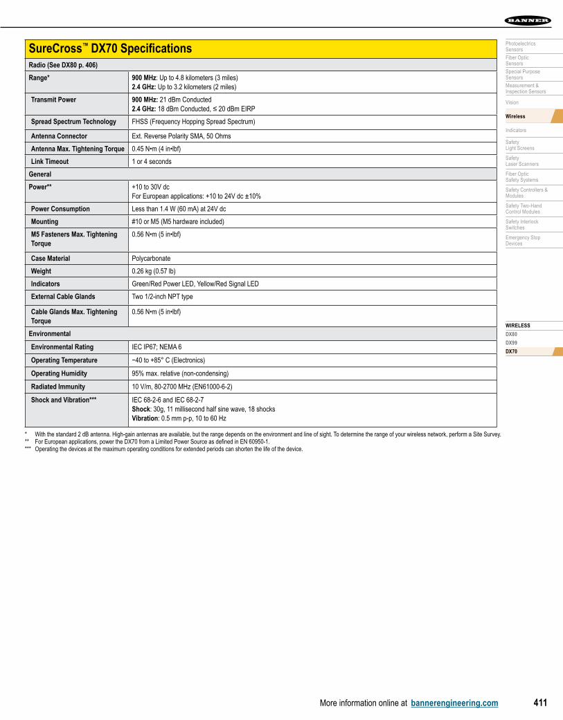
SureCross™ DX70 SpecificationsRadio (See DX80 p. 406)
Range* 900 MHz: Up to 4.8 kilometers (3 miles)2.4 GHz: Up to 3.2 kilometers (2 miles)
Transmit Power 900 MHz: 21 dBm Conducted2.4 GHz: 18 dBm Conducted, ≤ 20 dBm EIRP
Spread Spectrum Technology FHSS (Frequency Hopping Spread Spectrum)
Antenna Connector Ext. Reverse Polarity SMA, 50 Ohms
Antenna Max. Tightening Torque 0.45 N•m (4 in•lbf)
Link Timeout 1 or 4 seconds
General
Power** +10 to 30V dcFor European applications: +10 to 24V dc ±10%
Power Consumption Less than 1.4 W (60 mA) at 24V dc
Mounting #10 or M5 (M5 hardware included)
M5 Fasteners Max. Tightening Torque
0.56 N•m (5 in•lbf)
Case Material Polycarbonate
Weight 0.26 kg (0.57 lb)
Indicators Green/Red Power LED, Yellow/Red Signal LED
External Cable Glands Two 1/2-inch NPT type
Cable Glands Max. Tightening Torque
0.56 N•m (5 in•lbf)
Environmental
Environmental Rating IEC IP67; NEMA 6
Operating Temperature −40 to +85° C (Electronics)
Operating Humidity 95% max. relative (non-condensing)
Radiated Immunity 10 V/m, 80-2700 MHz (EN61000-6-2)
Shock and Vibration*** IEC 68-2-6 and IEC 68-2-7 Shock: 30g, 11 millisecond half sine wave, 18 shocks Vibration: 0.5 mm p-p, 10 to 60 Hz
* With the standard 2 dB antenna. High-gain antennas are available, but the range depends on the environment and line of sight. To determine the range of your wireless network, perform a Site Survey.** For European applications, power the DX70 from a Limited Power Source as defined in EN 60950-1.*** Operating the devices at the maximum operating conditions for extended periods can shorten the life of the device.

WIR
ELES
S DX80 DX99 DX70
More information online at bannerengineering.com412
FlexPower AccessoriesDescription Model
FlexPower Battery 6-pack delivers and manages
dc voltage from six 3.6V lithium D cell batteries.
Replacement battery pack: BWA-BATT-002
DX81P6
FlexPower Battery Supply Module delivers and
manages dc voltage from one 3.6V lithium D cell battery.
Replacement battery: BWA-BATT-001
DX81
FlexPower Battery Supply Module delivers and
manages dc voltage from one 3.6V lithium D cell
battery and used to power the polycarbonate housed
Intrinsically Safe DX99 devices.
DX81H
FlexPower Solar Supply includes solar panel,
controller, and rechargeable battery pack.
Replacement battery pack: BWA-BATT-003
BWA-SOLAR-001
Sensors Optimized for FlexPower DevicesDescription Model
The low-power MINI-BEAM is designed to work with the FlexPower Nodes.
Retro: SM312LPQD-78447
Diffuse: SM312DQD-78419
A long-range ultrasonic sensor designed to work with the FlexPower Nodes.
QT50ULBQ6-75390
See page 405 for serial sensor optimized for FlexPower.
Euro QDSee page 661
Length
Threaded 5-Pin
Straight Right-Angle0.5 m MQDC1-501.5 —
2 m MQDC1-506 MQDC1-506RA
5 m MQDC1-515 MQDC1-515RA
9 m MQDC1-530 MQDC1-530RA
Cordsets
Additional cordset information available.See page 655.
Additional bracket information available.See page 601.
BracketsDX80 DX99
SMBDX80DIN BWA-HW-019 BWA-HW-020
pg. 631
EnclosuresDescription Model
Enclosure Fiberglass Hinged 14"x12"x8" BWA-EF14128
Enclosure Fiberglass Hinged 10"x8"x6" BWA-EF1086
Enclosure Fiberglass Hinged 8"x6"x6" BWA-EF866
Panel, 14 x 12 BWA-PA1412
Panel, 10 x 8 BWA-PA108
Panel, 8 x 6 BWA-PA86
Pole Mount, 12 inch BWA-PM12
Pole Mount, 8 inch BWA-PM8
Pole Mount, 6 inch BWA-PM6
DC Power Supplies, 24V dcDescription Model
500 mA, Demo kit power supply PS24W
700 mA, 5-pin Euro-style QD, Hardwired AC power connection EZAC-E-QE5
200 mA, DX80 low-profile housing PS24DX
Relay BoxDescription Model
Interface Relay Box, 18-26V dc inputs, isolated relay outputs IB6RP
User Configuration Tool RS-485 to USB Adapter CableBWA-HW-006 RS-485 to USB adapter cable is used to connect the DX80 Gateway to a computer. Download your free configuration software at bannerengineering.com/wireless
BWA-HW-006
K50 Optimized for FlexPower DevicesDescription Model
K50 EZ-LIGHT, 3 color, with push button K50FGYRPB1Q

WIRELESS
DX80
DX99
DX70
More information online at bannerengineering.com 413
PhotoelectricsSensors
Fiber OpticSensors
Special PurposeSensors
Measurement & Inspection Sensors
Vision
Wireless
Indicators
Safety Light Screens
Safety Laser Scanners
Fiber OpticSafety Systems
Safety Controllers & Modules
Safety Two-Hand Control Modules
Safety Interlock Switches
Emergency Stop Devices
Antenna Cables
RP-SMA Male to N MaleLength Straight Model
0.5 m BWC-1MRSMN05
2 m BWC-1MRSMN2
RP-SMA to RP-SMA BulkheadLength Straight Model
0.2 m BWC-1MRSFRSB0.2
1 m BWC-1MRSFRSB1
2 m BWC-1MRSFRSB2
4 m BWC-1MRSFRSB4
LMR400 N Male to N FemaleLength Straight Model
3 m BWC-4MNFN3
6 m BWC-4MNFN6
15 m BWC-4MNFN15
30 m BWC-4MNFN30
AntennasDescription Model
6.5 dBd Yagi,900 MHz with
N FemaleBWA-9Y6-A
10 dBd Yagi withN Female pigtail
connectorBWA-9Y10-A
905-B
906-A
6 dBd OMNI,900 MHz, Fiberglass
with N FemaleBWA-9O6-A
5 dBd OMNI, fiberglass with ground
plane and N Female pigtail
connector
BWA-9O5-B
202-C
205-C
207-C
902-C
2.4 GHz OMNI,2 dBi, Rubber Swivel,
RP-SMA Male BWA-2O2-C
2.4 GHz OMNI,5 dBi, Rubber Swivel,
RP-SMA MaleBWA-2O5-C
2.4 GHz OMNI, 7 dBi, Rubber Swivel,
RP-SMA MaleBWA-2O7-C
900 MHz OMNI,2 dBi, RP-SMA Male
BWA-9O2-C
2.4 GHz OMNI,6 dBi, Fiberglass,
16 inches, OutdoorBWA-2O6-A
2.4 GHz OMNI,8.5 dBi, Fiberglass,24 inches, Outdoor
BWA-2O8-A
Surge Protection
Description Model
900 MHz/2.4 GHz surge suppressor with bulkhead N
connectorBWC-LFNBMN
900 MHz/2.4 GHz surge suppressor with bulkhead and
RP-SMABWC-LMRSFRPB
Surge suppressor, bulkhead, N-Type and dc Blocking
BWC-LFNBMN-DC
Antenna Feed ThroughsDescription Model
Antenna Feed through,SS, 1/2" NPT
BWA-HW-016
Antenna Feed through,SS, 3/4" NPT
BWA-HW-017


![DRIVEN BY VISIBILITY...Daewoo Cielo [T-Car] 1995.07 2001.03 3 397 011 646 3 397 011 646 3 397 005 293 3 397 016 578 3 397 016 578 Matiz 1998.11 2002.02 3 397 011 650 3 397 011 643](https://img.pdfslide.us/doc/110x75/6112d7f249975425bc587ce5/driven-by-visibility-daewoo-cielo-t-car-199507-200103-3-397-011-646-3-397.jpg)


![[ENG] 397 Manolona](https://img.pdfslide.us/doc/110x75/568c4dbb1a28ab4916a51e37/eng-397-manolona.jpg)