Embed Size (px)
DESCRIPTION
Special Purpose Sensors:- Optical Touch Buttons p290 • OTB/LTB • VTB • STB Part and Area p263 • LX Registration and Color p276 • R58 • QC50/QCX50, Part and Area, Slot and Label, Registration and Color, Luminescence, Pick-to-Light Sensors p431
Citation preview
SEN
SOR
S
More information online at bannerengineering.com262
PART & AREA SLOT & LABEL REgiSTRATiOn & COLOR LUMinESCEnCE OPTiCAL TOUCH BUTTOnS
Part & Area page 263
• LX
Registration & Color page 276
• R58
• QC50/QCX50
Slot & Label page 266
• SLM
• SL
• SLC1
Optical Touch Buttons page 290
• OTB/LTB
• VTB
• STB
Luminescence page 283
• QL50
• QL51
• QL56
Pick-to-Light Sensors page 431• K50 and K80 low-cost, self-contained
sensors for bin-picking operations• Ultra-bright optical touch buttons
for indicating bin-picking sequences• Two- or one-component light sensors for
part assembly and error proofing
PART & AREA
LX
SLOT & LABEL
REGISTRATION & COLOR
LUMINESCENCE
OPTICAL TOUCHBUTTONS
More information online at bannerengineering.com 263
PhotoelectricsSensors
Fiber OpticSensors
Special PurposeSensors
Measurement & Inspection Sensors
Vision
Wireless
Indicators
Safety Light Screens
Safety Laser Scanners
Fiber OpticSafety Systems
Safety Controllers & Modules
Safety Two-Hand Control Modules
Safety Interlock Switches
Emergency Stop Devices
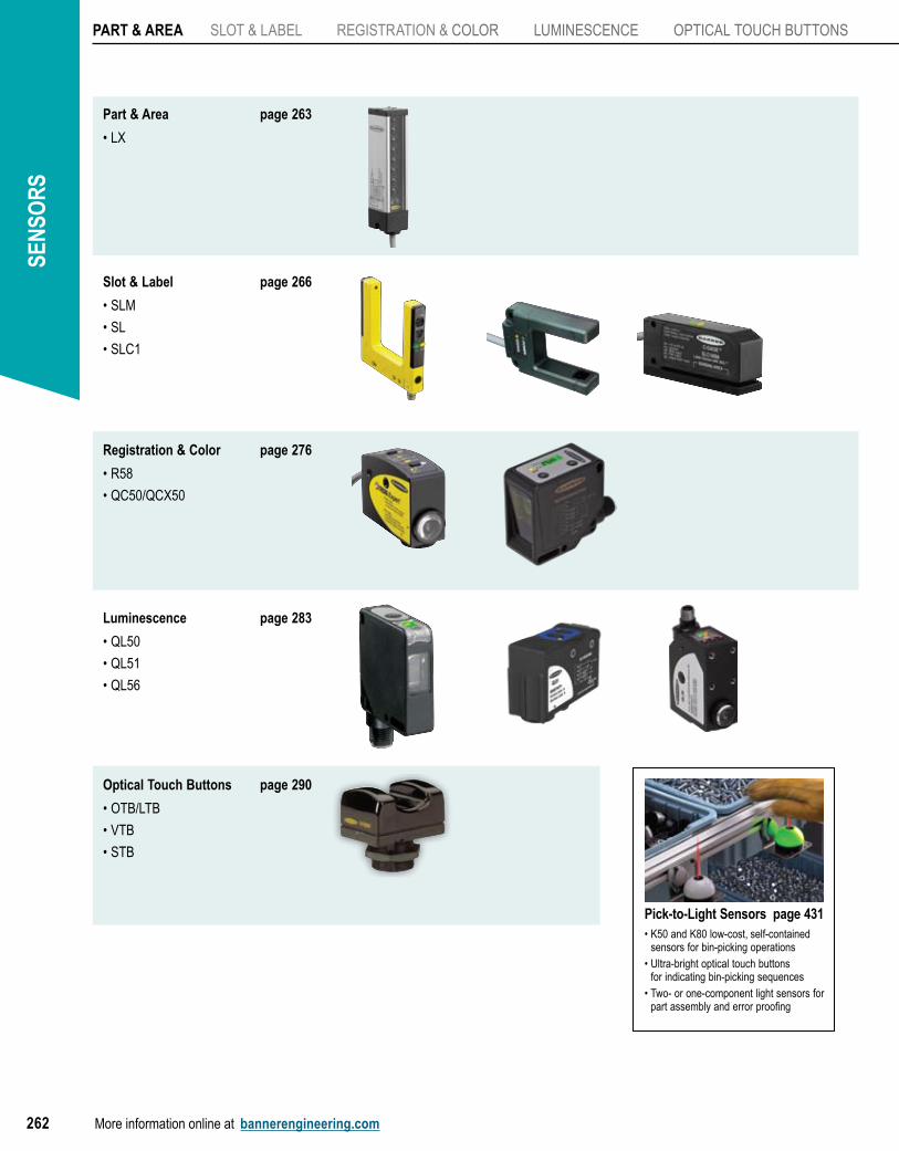
LXHigh-Speed Part-Sensing Light Screen• Generates a multiple-beam infrared pattern for extraordinary sensitively to
small objects
• Detects objects as small as 5.6 mm and extremely flat objects that pass anywhere through the light screen
• Ideal for die-protection (part ejection verification), small part or pill counting, parcel handling and sorting by height
• Responds in 0.8 to 6.4 milliseconds–faster than comparable products, even at its slowest response speed
• Enables automated systems to operate at peek efficiency
• Features rugged silver anodized housing with IP65 rating
• Uses integrated T-slot mounting channel for unique mounting flexibility
LX Series optical crosshatch pattern
Sensing is most effective in the center 80% of the range
Emitter Receiver
LX Light Screens, 10-30V dc
Sensing Array Length
Short-Range (75-200 mm)Min object detection size: 5.6 mm dia.
Standard Range (150 mm - 2 m)Min object detection size: 9.5 mm dia.
ConnectionOutput TypeEmitters Receivers Emitters Receivers
67 mm LX3ESR LX3RSR LX3E LX3R
2 mBipolar
NPN/PNP
143 mm LX6ESR LX6RSR LX6E LX6R
218 mm – – LX9E LX9R
295 mm LX12ESR LX12RSR LX12E LX12R
Models Length (L)LX3 113.4 mm
LX6 189.6 mm
LX9 265.8 mm
LX12 342.0 mm
LX15 418.2 mm
LX18 494.4 mm
LX21 570.6 mm
LX24 646.8 mm
ONLINE
AUTOCAD, STEP, IGES & PDF
L
31.8 mm25.4 mm
Moreon next page
ACCESSORIES
page265
Connection options: A model with a QD requires a mating cordset (see page 265)
For 5-pin 150 mm Euro-style Pigtail QD, add suffix Q to the 2 m model number (example, LX3EQ).
SEN
SOR
S
More information online at bannerengineering.com264
PART & AREA SLOT & LABEL REGIsTRaTIon & CoLoR LUMInEsCEnCE oPTICaL ToUCH BUTTons
ACCESSORIES
page265
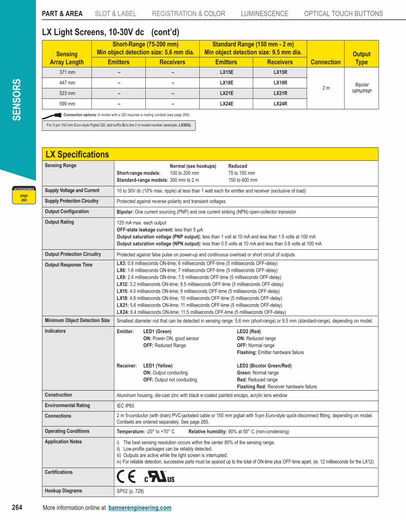
LX Specifications Sensing Range Normal (see hookups) Reduced
Short-range models: 100 to 200 mm 75 to 150 mmStandard-range models: 300 mm to 2 m 150 to 600 mm
Supply Voltage and Current 10 to 30V dc (10% max. ripple) at less than 1 watt each for emitter and receiver (exclusive of load)
Supply Protection Circuitry Protected against reverse polarity and transient voltages.
Output Configuration Bipolar: one current sourcing (PnP) and one current sinking (nPn) open-collector transistor
Output Rating 125 ma max. each outputOFF-state leakage current: less than 5 µaOutput saturation voltage (PNP output): less than 1 volt at 10 ma and less than 1.5 volts at 100 maOutput saturation voltage (NPN output): less than 0.5 volts at 10 ma and less than 0.6 volts at 100 ma
Output Protection Circuitry Protected against false pulse on power-up and continuous overload or short circuit of outputs
Output Response Time LX3: 0.8 milliseconds on-time; 6 milliseconds oFF-time (5 milliseconds oFF-delay)LX6: 1.6 milliseconds on-time; 7 milliseconds oFF-time (5 milliseconds oFF-delay)LX9: 2.4 milliseconds on-time; 7.5 milliseconds oFF-time (5 milliseconds oFF-delay)LX12: 3.2 milliseconds on-time; 8.5 milliseconds oFF-time (5 milliseconds oFF-delay)LX15: 4.0 milliseconds on-time; 9 milliseconds oFF-time (5 milliseconds oFF-delay)LX18: 4.8 milliseconds on-time; 10 milliseconds oFF-time (5 milliseconds oFF-delay)LX21: 5.6 milliseconds on-time; 11 milliseconds oFF-time (5 milliseconds oFF-delay)LX24: 6.4 milliseconds on-time; 11.5 milliseconds oFF-time (5 milliseconds oFF-delay)
Minimum Object Detection Size smallest diameter rod that can be detected in sensing range: 5.6 mm (short-range) or 9.5 mm (standard-range), depending on model.
Indicators Emitter: LED1 (Green) LED2 (Red) ON: Power on, good sensor ON: Reduced range OFF: Reduced Range OFF: Normal range Flashing: Emitter hardware failure
Receiver: LED1 (Yellow) LED2 (Bicolor Green/Red) ON: Output conducting Green: Normal range OFF: Output not conducting Red: Reduced range Flashing Red: Receiver hardware failure
Construction aluminum housing, die-cast zinc with black e-coated painted encaps, acrylic lens window
Environmental Rating IEC IP65
Connections 2 m 5-conductor (with drain) PVC-jacketed cable or 150 mm pigtail with 5-pin Euro-style quick-disconnect fitting, depending on model. Cordsets are ordered separately. see page 265.
Operating Conditions Temperature: -20° to +70° C Relative humidity: 90% at 50° C (non-condensing)
Application Notes i) The best sensing resolution occurs within the center 80% of the sensing range.ii) Low-profile packages can be reliably detected.iii) outputs are active while the light screen is interrupted.iv) For reliable detection, successive parts must be spaced up to the total of on-time plus oFF-time apart. (ie. 12 milliseconds for the LX12)
Certifications
Hookup Diagrams sP02 (p. 728)
LX Light Screens, 10-30V dc
Sensing Array Length
Short-Range (75-200 mm)Min object detection size: 5.6 mm dia.
Standard Range (150 mm - 2 m)Min object detection size: 9.5 mm dia.
ConnectionOutput TypeEmitters Receivers Emitters Receivers
371 mm – – LX15E LX15R
2 mBipolar
NPN/PNP
447 mm – – LX18E LX18R
523 mm – – LX21E LX21R
599 mm – – LX24E LX24R
(cont’d)
Connection options: A model with a QD requires a mating cordset (see page 265)
For 5-pin 150 mm Euro-style Pigtail QD, add suffix Q to the 2 m model number (example, LX3EQ).
PART & AREA
LX
SLOT & LABEL
REGISTRATION & COLOR
LUMINESCENCE
OPTICAL TOUCHBUTTONS
More information online at bannerengineering.com 265
PhotoelectricsSensors
Fiber OpticSensors
Special PurposeSensors
Measurement & Inspection Sensors
Vision
Wireless
Indicators
Safety Light Screens
Safety Laser Scanners
Fiber OpticSafety Systems
Safety Controllers & Modules
Safety Two-Hand Control Modules
Safety Interlock Switches
Emergency Stop Devices
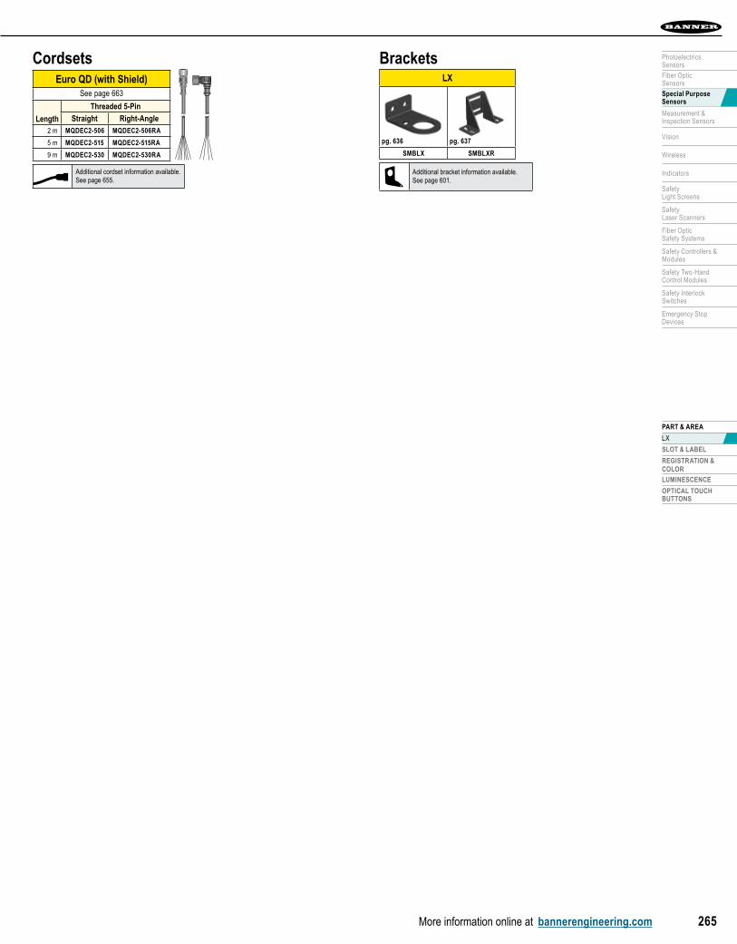
BracketsLX
SMBLX SMBLXR
pg. 636 pg. 637
Euro QD (with Shield)See page 663
Length
Threaded 5-Pin
Straight Right-Angle2 m MQDEC2-506 MQDEC2-506RA
5 m MQDEC2-515 MQDEC2-515RA
9 m MQDEC2-530 MQDEC2-530RA
Cordsets
Additional cordset information available.See page 655.
Additional bracket information available.See page 601.
SEN
SOR
S
More information online at bannerengineering.com266
PART & AREA SLOT & LABEL REgiSTRATiOn & COLOR LUMinESCEnCE OPTiCAL TOUCH BUTTOnS
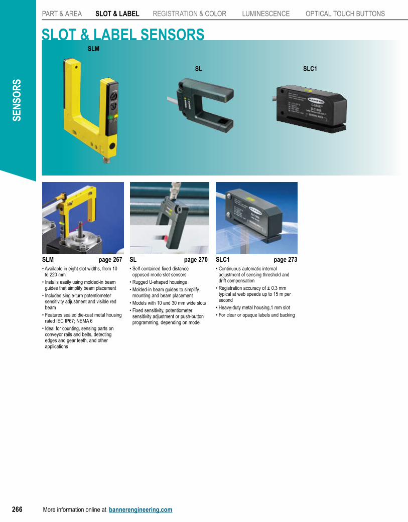
SLM page 267• Available in eight slot widths, from 10
to 220 mm• Installs easily using molded-in beam
guides that simplify beam placement• Includes single-turn potentiometer
sensitivity adjustment and visible red beam
• Features sealed die-cast metal housing rated IEC IP67; NEMA 6
• Ideal for counting, sensing parts on conveyor rails and belts, detecting edges and gear teeth, and other applications
SL page 270• Self-contained fixed-distance
opposed-mode slot sensors• Rugged U-shaped housings• Molded-in beam guides to simplify
mounting and beam placement• Models with 10 and 30 mm wide slots• Fixed sensitivity, potentiometer
sensitivity adjustment or push-button programming, depending on model
SLC1 page 273• Continuous automatic internal
adjustment of sensing threshold and drift compensation
• Registration accuracy of ± 0.3 mm typical at web speeds up to 15 m per second
• Heavy-duty metal housing,1 mm slot• For clear or opaque labels and backing
SLOT & LABEL SENSORS
SLC1SL
SLM
PART & AREA
SLOT & LABEL
SLM
SL
SLC1
REGISTRATION & COLOR
LUMINESCENCE
OPTICAL TOUCHBUTTONS
More information online at bannerengineering.com 267
PhotoelectricsSensors
Fiber OpticSensors
Special PurposeSensors
Measurement & Inspection Sensors
Vision
Wireless
Indicators
Safety Light Screens
Safety Laser Scanners
Fiber OpticSafety Systems
Safety Controllers & Modules
Safety Two-Hand Control Modules
Safety Interlock Switches
Emergency Stop Devices
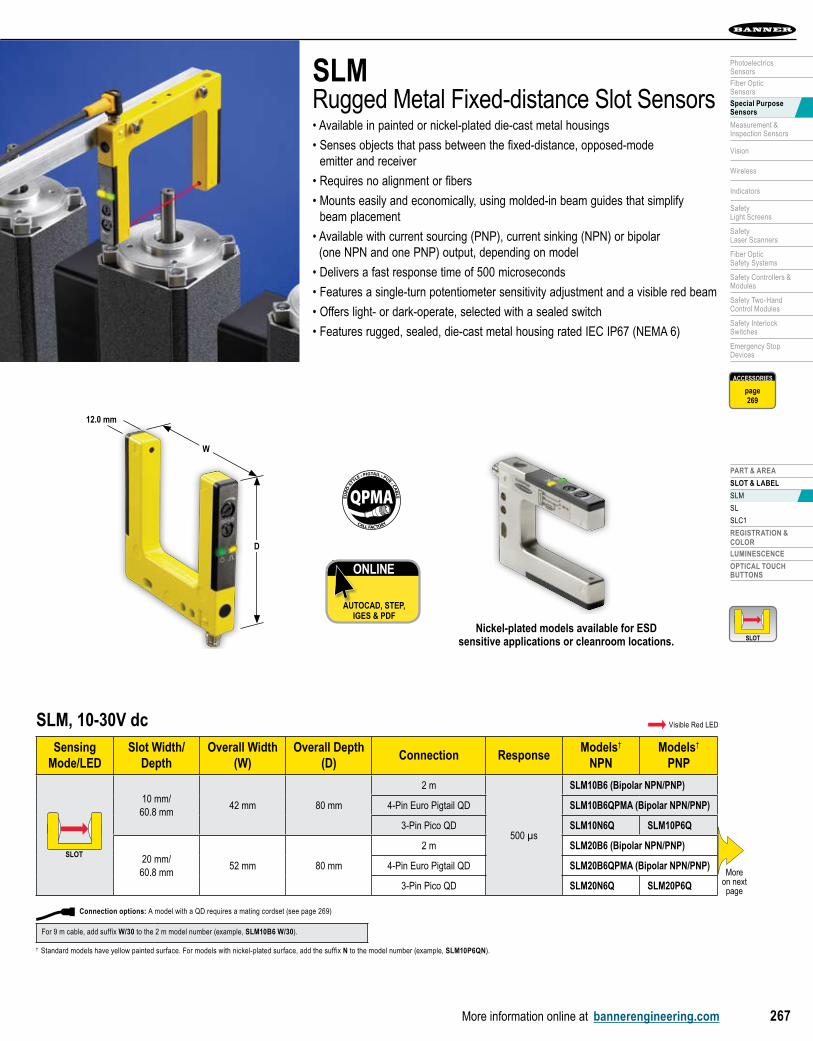
SLM, 10-30V dcSensing
Mode/LEDSlot Width/
DepthOverall Width
(W) Overall Depth
(D)Connection Response
Models†
NPNModels†
PNP
SLOTSLOT
10 mm/60.8 mm
42 mm 80 mm
2 m
500 µs
SLM10B6 (Bipolar NPN/PNP)
4-Pin Euro Pigtail QD SLM10B6QPMA (Bipolar NPN/PNP)
3-Pin Pico QD SLM10N6Q SLM10P6Q
20 mm/60.8 mm
52 mm 80 mm
2 m SLM20B6 (Bipolar NPN/PNP)
4-Pin Euro Pigtail QD SLM20B6QPMA (Bipolar NPN/PNP)
3-Pin Pico QD SLM20N6Q SLM20P6Q
QPMAEURO
-STYLE • PIGTAIL • PUR • CABLE
CALL FACTORY
SLMRugged Metal Fixed-distance Slot Sensors• Available in painted or nickel-plated die-cast metal housings
• Senses objects that pass between the fixed-distance, opposed-mode emitter and receiver
• Requires no alignment or fibers
• Mounts easily and economically, using molded-in beam guides that simplify beam placement
• Available with current sourcing (PNP), current sinking (NPN) or bipolar (one NPN and one PNP) output, depending on model
• Delivers a fast response time of 500 microseconds
• Features a single-turn potentiometer sensitivity adjustment and a visible red beam
• Offers light- or dark-operate, selected with a sealed switch
• Features rugged, sealed, die-cast metal housing rated IEC IP67 (NEMA 6)
Nickel-plated models available for ESD sensitive applications or cleanroom locations.
ONLINE
AUTOCAD, STEP, IGES & PDF
† Standard models have yellow painted surface. For models with nickel-plated surface, add the suffix N to the model number (example, SLM10P6QN).
Moreon next page
Visible Red LED
D
W
12.0 mm
SLOTSLOT
ACCESSORIES
page269
Connection options: A model with a QD requires a mating cordset (see page 269)
For 9 m cable, add suffix W/30 to the 2 m model number (example, SLM10B6 W/30).
SEN
SOR
S
More information online at bannerengineering.com268
PART & AREA SLOT & LABEL REgiSTRATiOn & COLOR LUMinESCEnCE OPTiCAL TOUCH BUTTOnS
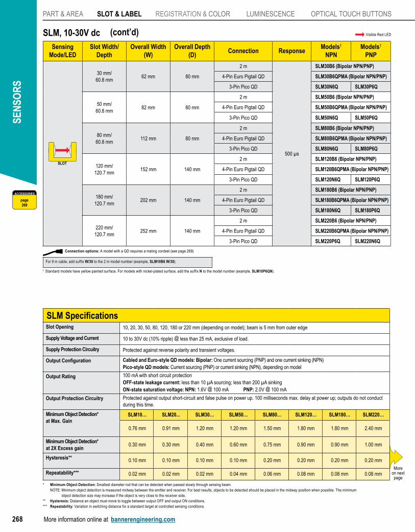
SLM, 10-30V dcSensing
Mode/LEDSlot Width/
DepthOverall Width
(W) Overall Depth
(D)Connection Response
Models†
NPNModels†
PNP
SLOTSLOT
30 mm/60.8 mm
62 mm 80 mm
2 m
500 µs
SLM30B6 (Bipolar NPN/PNP)
4-Pin Euro Pigtail QD SLM30B6QPMA (Bipolar NPN/PNP)
3-Pin Pico QD SLM30N6Q SLM30P6Q
50 mm/60.8 mm
82 mm 80 mm
2 m SLM50B6 (Bipolar NPN/PNP)
4-Pin Euro Pigtail QD SLM50B6QPMA (Bipolar NPN/PNP)
3-Pin Pico QD SLM50N6Q SLM50P6Q
80 mm/60.8 mm
112 mm 80 mm
2 m SLM80B6 (Bipolar NPN/PNP)
4-Pin Euro Pigtail QD SLM80B6QPMA (Bipolar NPN/PNP)
3-Pin Pico QD SLM80N6Q SLM80P6Q
120 mm/120.7 mm
152 mm 140 mm
2 m SLM120B6 (Bipolar NPN/PNP)
4-Pin Euro Pigtail QD SLM120B6QPMA (Bipolar NPN/PNP)
3-Pin Pico QD SLM120N6Q SLM120P6Q
180 mm/120.7 mm
202 mm 140 mm
2 m SLM180B6 (Bipolar NPN/PNP)
4-Pin Euro Pigtail QD SLM180B6QPMA (Bipolar NPN/PNP)
3-Pin Pico QD SLM180N6Q SLM180P6Q
220 mm/120.7 mm
252 mm 140 mm
2 m SLM220B6 (Bipolar NPN/PNP)
4-Pin Euro Pigtail QD SLM220B6QPMA (Bipolar NPN/PNP)
3-Pin Pico QD SLM220P6Q SLM220N6Q
(cont’d)
SLM SpecificationsSlot Opening 10, 20, 30, 50, 80, 120, 180 or 220 mm (depending on model); beam is 5 mm from outer edge
Supply Voltage and Current 10 to 30V dc (10% ripple) @ less than 25 mA, exclusive of load.
Supply Protection Circuitry Protected against reverse polarity and transient voltages.
Output Configuration Cabled and Euro-style QD models: Bipolar: One current sourcing (PNP) and one current sinking (NPN)Pico-style QD models: Current sourcing (PNP) or current sinking (NPN), depending on model
Output Rating 100 mA with short circuit protection OFF-state leakage current: less than 10 µA sourcing; less than 200 µA sinkingON-state saturation voltage: NPN: 1.6V @ 100 mA PNP: 2.0V @ 100 mA
Output Protection Circuitry Protected against output short-circuit and false pulse on power up. 100 milliseconds max. delay at power up; outputs do not conduct during this time.
Minimum Object Detection* at Max. Gain
SLM10… SLM20... SLM30… SLM50… SLM80… SLM120… SLM180… SLM220…
0.76 mm 0.91 mm 1.20 mm 1.20 mm 1.50 mm 1.80 mm 1.80 mm 2.40 mm
Minimum Object Detection* at 2X Excess gain
0.30 mm 0.30 mm 0.40 mm 0.60 mm 0.75 mm 0.90 mm 0.90 mm 1.00 mm
Hysteresis** 0.10 mm 0.10 mm 0.10 mm 0.10 mm 0.20 mm 0.20 mm 0.20 mm 0.20 mm
Repeatability*** 0.02 mm 0.02 mm 0.02 mm 0.04 mm 0.06 mm 0.08 mm 0.08 mm 0.08 mmMore
on next page
Visible Red LED
ACCESSORIES
page269
† Standard models have yellow painted surface. For models with nickel-plated surface, add the suffix N to the model number (example, SLM10P6QN).
* Minimum Object Detection: Smallest diameter rod that can be detected when passed slowly through sensing beam. NOTE: Minimum object detection is measured midway between the emitter and receiver. For best results, objects to be detected should be placed in the midway position when possible. The minimum
object detection size may increase if the object is very close to the receiver side.** Hysteresis: Distance an object must move to toggle between output OFF and output ON conditions.*** Repeatability: Variation in switching distance for a standard target at controlled sensing conditions.
Connection options: A model with a QD requires a mating cordset (see page 269)
For 9 m cable, add suffix W/30 to the 2 m model number (example, SLM10B6 W/30).
PART & AREA
SLOT & LABEL
SLM
SL
SLC1
REGISTRATION & COLOR
LUMINESCENCE
OPTICAL TOUCHBUTTONS
More information online at bannerengineering.com 269
PhotoelectricsSensors
Fiber OpticSensors
Special PurposeSensors
Measurement & Inspection Sensors
Vision
Wireless
Indicators
Safety Light Screens
Safety Laser Scanners
Fiber OpticSafety Systems
Safety Controllers & Modules
Safety Two-Hand Control Modules
Safety Interlock Switches
Emergency Stop Devices
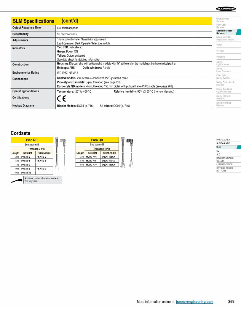
SLM SpecificationsOutput Response Time 500 microseconds
Repeatability 95 microseconds
Adjustments 1-turn potentiometer Sensitivity adjustment Light Operate / Dark Operate Selection switch
Indicators Two LED Indicators: Green: Power ON Yellow: Output activatedSee data sheet for detailed information
Construction Housing: Die-cast zinc with yellow paint; models with “N” at the end of the model number have nickel plating Endcaps: ABS Optic windows: Acrylic
Environmental Rating IEC IP67; NEMA 6
Connections Cabled models: 2 m or 9 m 4-conductor, PVC-jacketed cablePico-style QD models: 3-pin, threaded (see page 269)Euro-style QD models: 4-pin, threaded 150 mm pigtail with polyurethane (PUR) cable (see page 269)
Operating Conditions Temperature: -20° to +60° C Relative humidity: 95% @ 55° C (non-condensing)
Certifications
Hookup Diagrams Bipolar Models: DC04 (p. 716) All others: DC01 (p. 716)
(cont’d)
Pico QDSee page 655
Length
Threaded 3-Pin
Straight Right-Angle2 m PKG3M-2 PKW3M-2
5 m PKG3M-5 PKW3M-5
7 m PKG3M-7 —
9 m PKG3M-9 PKW3M-9
10 m PKG3M-10 —
Cordsets
Additional cordset information available.See page 655.
Euro QDSee page 658
Length
Threaded 4-Pin
Straight Right-Angle2 m MQDC-406 MQDC-406RA
5 m MQDC-415 MQDC-415RA
9 m MQDC-430 MQDC-430RA
SEN
SOR
S
More information online at bannerengineering.com270
PART & AREA SLOT & LABEL REgiSTRATiOn & COLOR LUMinESCEnCE OPTiCAL TOUCH BUTTOnS
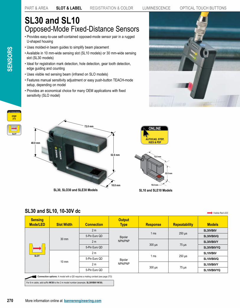
SL10 and SLE10 Models
18.8 mm
72.0 mm
52.0 mm
SL30 and SL10Opposed-Mode Fixed-Distance Sensors• Provides easy-to-use self-contained opposed-mode sensor pair in a rugged
U-shaped housing
• Uses molded-in beam guides to simplify beam placement
• Available in 10 mm-wide sensing slot (SL10 models) or 30 mm-wide sensing slot (SL30 models)
• Ideal for registration mark detection, hole detection, gear tooth detection, edge guiding and counting
• Uses visible red sensing beam (infrared on SLO models)
• Features manual sensitivity adjustment or easy push-button TEACH-mode setup, depending on model
• Provides an economical choice for many OEM applications with fixed sensitivity (SLO model)
ONLINE
AUTOCAD, STEP, IGES & PDF
SL30 and SL10, 10-30V dc
Sensing Mode/LED Slot Width Connection
OutputType Response Repeatability Models
SLOTSLOT
30 mm
2 m
BipolarNPN/PNP
1 ms 250 µsSL30VB6V
5-Pin Euro QD SL30VB6VQ
2 m300 µs 75 µs
SL30VB6VY
5-Pin Euro QD SL30VB6VYQ
10 mm
2 m
BipolarNPN/PNP
1 ms 250 µsSL10VB6V
5-Pin Euro QD SL10VB6VQ
2 m300 µs 75 µs
SL10VB6VY
5-Pin Euro QD SL10VB6VYQ
Visible Red LED
SL30, SLO30 and SLE30 Models
72.0 mm
52.0 mm
18.8 mm
ACCESSORIES
page272
SLOTSLOT
40.0 mm
Connection options: A model with a QD requires a mating cordset (see page 272)
For 9 m cable, add suffix W/30 to the 2 m model number (example, SL30VB6V W/30).
PART & AREA
SLOT & LABEL
SLM
SL
SLC1
REGISTRATION & COLOR
LUMINESCENCE
OPTICAL TOUCHBUTTONS
More information online at bannerengineering.com 271
PhotoelectricsSensors
Fiber OpticSensors
Special PurposeSensors
Measurement & Inspection Sensors
Vision
Wireless
Indicators
Safety Light Screens
Safety Laser Scanners
Fiber OpticSafety Systems
Safety Controllers & Modules
Safety Two-Hand Control Modules
Safety Interlock Switches
Emergency Stop Devices
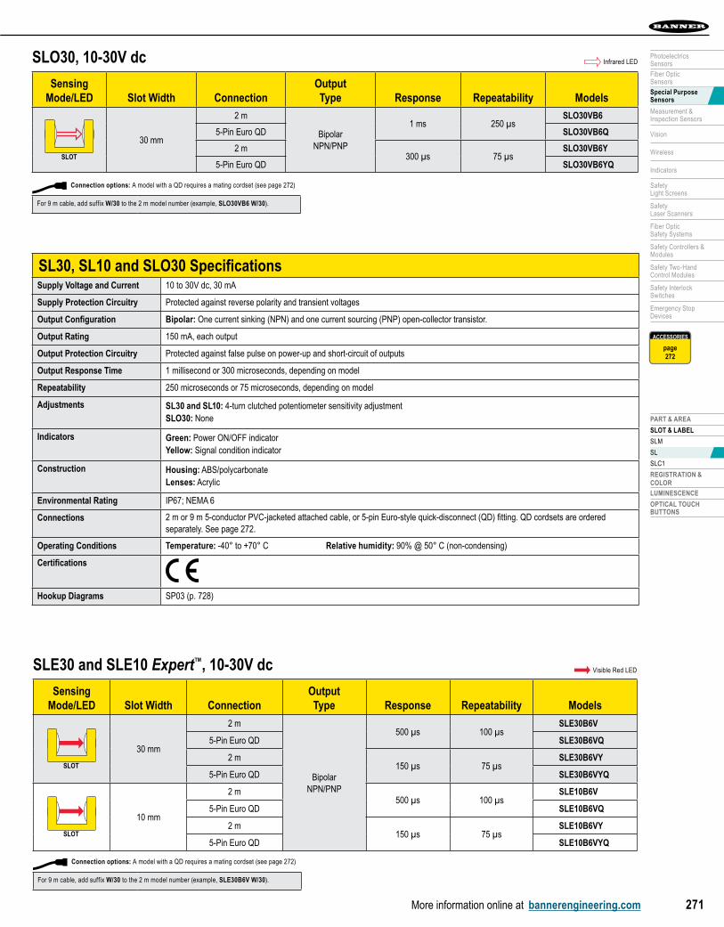
SL30, SL10 and SLO30 SpecificationsSupply Voltage and Current 10 to 30V dc, 30 mA
Supply Protection Circuitry Protected against reverse polarity and transient voltages
Output Configuration Bipolar: One current sinking (NPN) and one current sourcing (PNP) open-collector transistor.
Output Rating 150 mA, each output
Output Protection Circuitry Protected against false pulse on power-up and short-circuit of outputs
Output Response Time 1 millisecond or 300 microseconds, depending on model
Repeatability 250 microseconds or 75 microseconds, depending on model
Adjustments SL30 and SL10: 4-turn clutched potentiometer sensitivity adjustmentSLO30: none
Indicators Green: Power ON/OFF indicatorYellow: Signal condition indicator
Construction Housing: ABS/polycarbonateLenses: Acrylic
Environmental Rating IP67; NEMA 6
Connections 2 m or 9 m 5-conductor PVC-jacketed attached cable, or 5-pin Euro-style quick-disconnect (QD) fitting. QD cordsets are ordered separately. See page 272.
Operating Conditions Temperature: -40° to +70° C Relative humidity: 90% @ 50° C (non-condensing)
Certifications
Hookup Diagrams SP03 (p. 728)
SLO30, 10-30V dc
Sensing Mode/LED Slot Width Connection
OutputType Response Repeatability Models
SLOTSLOT
30 mm
2 m
BipolarNPN/PNP
1 ms 250 µsSLO30VB6
5-Pin Euro QD SLO30VB6Q
2 m300 µs 75 µs
SLO30VB6Y
5-Pin Euro QD SLO30VB6YQ
Infrared LED
ACCESSORIES
page272
SLE30 and SLE10 Expert™, 10-30V dc
Sensing Mode/LED Slot Width Connection
OutputType Response Repeatability Models
SLOTSLOT
30 mm
2 m
BipolarNPN/PNP
500 µs 100 µsSLE30B6V
5-Pin Euro QD SLE30B6VQ
2 m150 µs 75 µs
SLE30B6VY
5-Pin Euro QD SLE30B6VYQ
SLOTSLOT
10 mm
2 m500 µs 100 µs
SLE10B6V
5-Pin Euro QD SLE10B6VQ
2 m150 µs 75 µs
SLE10B6VY
5-Pin Euro QD SLE10B6VYQ
Visible Red LED
Connection options: A model with a QD requires a mating cordset (see page 272)
For 9 m cable, add suffix W/30 to the 2 m model number (example, SLO30VB6 W/30).
Connection options: A model with a QD requires a mating cordset (see page 272)
For 9 m cable, add suffix W/30 to the 2 m model number (example, SLE30B6V W/30).
SEN
SOR
S
More information online at bannerengineering.com272
PART & AREA SLOT & LABEL REgiSTRATiOn & COLOR LUMinESCEnCE OPTiCAL TOUCH BUTTOnS
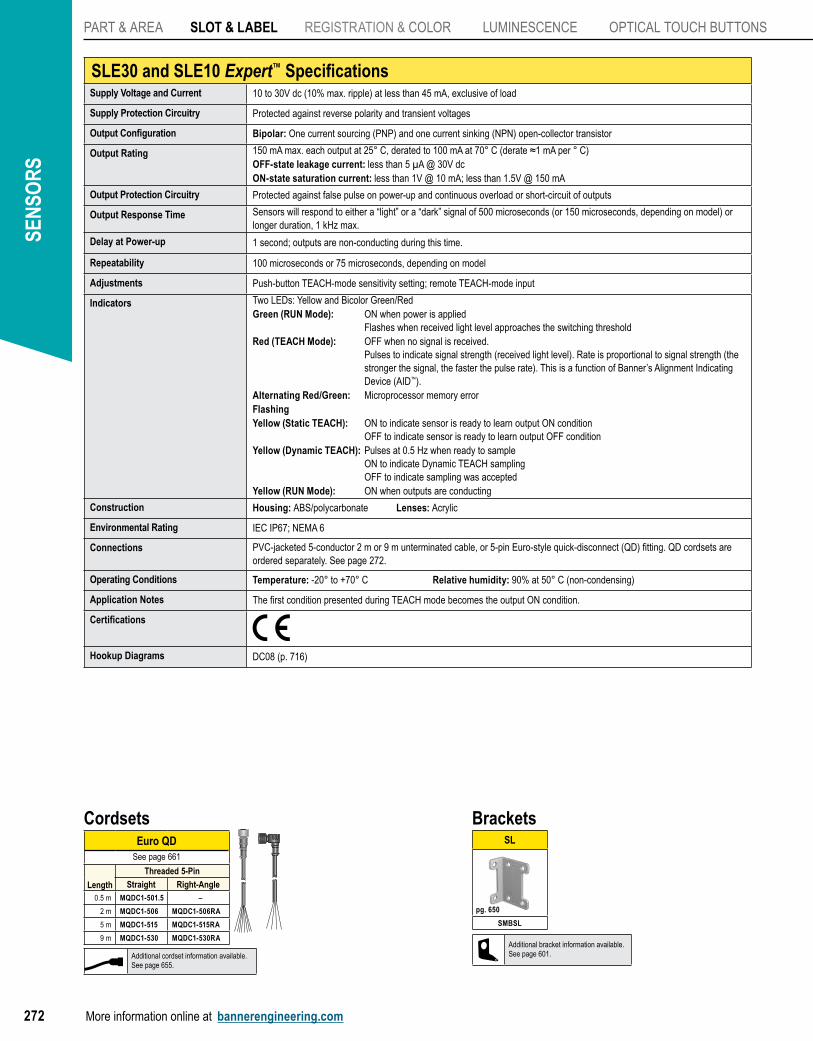
SLE30 and SLE10 Expert™ SpecificationsSupply Voltage and Current 10 to 30V dc (10% max. ripple) at less than 45 mA, exclusive of load
Supply Protection Circuitry Protected against reverse polarity and transient voltages
Output Configuration Bipolar: One current sourcing (PNP) and one current sinking (NPN) open-collector transistor
Output Rating 150 mA max. each output at 25° C, derated to 100 mA at 70° C (derate ≈1 mA per ° C)OFF-state leakage current: less than 5 µA @ 30V dcON-state saturation current: less than 1V @ 10 mA; less than 1.5V @ 150 mA
Output Protection Circuitry Protected against false pulse on power-up and continuous overload or short-circuit of outputs
Output Response Time Sensors will respond to either a “light” or a “dark” signal of 500 microseconds (or 150 microseconds, depending on model) or longer duration, 1 kHz max.
Delay at Power-up 1 second; outputs are non-conducting during this time.
Repeatability 100 microseconds or 75 microseconds, depending on model
Adjustments Push-button TEACH-mode sensitivity setting; remote TEACH-mode input
Indicators Two LEDs: Yellow and Bicolor Green/RedGreen (RUN Mode): ON when power is applied Flashes when received light level approaches the switching thresholdRed (TEACH Mode): OFF when no signal is received. Pulses to indicate signal strength (received light level). Rate is proportional to signal strength (the
stronger the signal, the faster the pulse rate). This is a function of Banner’s Alignment Indicating Device (AID™).
Alternating Red/Green: Microprocessor memory errorFlashingYellow (Static TEACH): ON to indicate sensor is ready to learn output ON condition OFF to indicate sensor is ready to learn output OFF conditionYellow (Dynamic TEACH): Pulses at 0.5 Hz when ready to sample ON to indicate Dynamic TEACH sampling OFF to indicate sampling was acceptedYellow (RUN Mode): ON when outputs are conducting
Construction Housing: ABS/polycarbonate Lenses: Acrylic
Environmental Rating IEC IP67; NEMA 6
Connections PVC-jacketed 5-conductor 2 m or 9 m unterminated cable, or 5-pin Euro-style quick-disconnect (QD) fitting. QD cordsets are ordered separately. See page 272.
Operating Conditions Temperature: -20° to +70° C Relative humidity: 90% at 50° C (non-condensing)
Application Notes The first condition presented during TEACH mode becomes the output ON condition.
Certifications
Hookup Diagrams DC08 (p. 716)
BracketsSL
SMBSL
pg. 650
Cordsets
Additional cordset information available.See page 655.
Additional bracket information available.See page 601.
Euro QDSee page 661
Length
Threaded 5-Pin
Straight Right-Angle0.5 m MQDC1-501.5 –
2 m MQDC1-506 MQDC1-506RA
5 m MQDC1-515 MQDC1-515RA
9 m MQDC1-530 MQDC1-530RA
PART & AREA
SLOT & LABEL
SLM
SL
SLC1
REGISTRATION & COLOR
LUMINESCENCE
OPTICAL TOUCHBUTTONS
More information online at bannerengineering.com 273
PhotoelectricsSensors
Fiber OpticSensors
Special PurposeSensors
Measurement & Inspection Sensors
Vision
Wireless
Indicators
Safety Light Screens
Safety Laser Scanners
Fiber OpticSafety Systems
Safety Controllers & Modules
Safety Two-Hand Control Modules
Safety Interlock Switches
Emergency Stop Devices
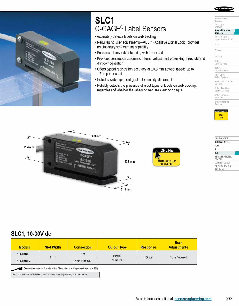
SLC1C-GAGE® Label Sensors• Accurately detects labels on web backing
• Requires no user adjustments—ADL™ (Adaptive Digital Logic) provides revolutionary self-learning capability
• Features a heavy-duty housing with 1 mm slot
• Provides continuous automatic internal adjustment of sensing threshold and drift compensation
• Offers typical registration accuracy of ±0.3 mm at web speeds up to 1.5 m per second
• Includes web alignment guides to simplify placement
• Reliably detects the presence of most types of labels on web backing, regardless of whether the labels or web are clear or opaque
ONLINE
AUTOCAD, STEP, IGES & PDF
SLC1, 10-30V dc
Models Slot Width Connection Output Type ResponseUser
Adjustments
SLC1BB61 mm
2 mBipolar
NPN/PNP 100 µs None Required
SLC1BB6Q 5-pin Euro QD
88.9 mm
40.8 mm
23.1 mm
25.4 mm
ACCESSORIES
page274
Connection options: A model with a QD requires a mating cordset (see page 274)
For 9 m cable, add suffix W/30 to the 2 m model number (example, SLC1BB6 W/30).
SEN
SOR
S
More information online at bannerengineering.com274
PART & AREA SLOT & LABEL REgiSTRATiOn & COLOR LUMinESCEnCE OPTiCAL TOUCH BUTTOnS
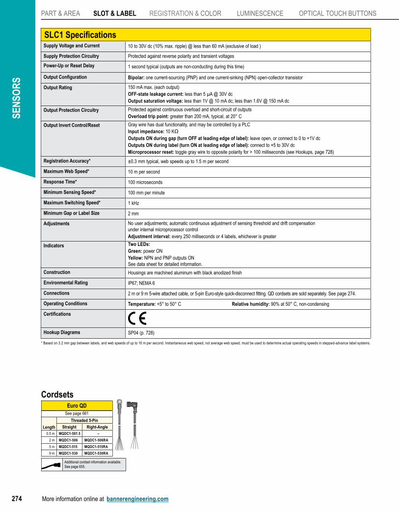
SLC1 SpecificationsSupply Voltage and Current 10 to 30V dc (10% max. ripple) @ less than 60 mA (exclusive of load )
Supply Protection Circuitry Protected against reverse polarity and transient voltages
Power-Up or Reset Delay 1 second typical (outputs are non-conducting during this time)
Output Configuration Bipolar: one current-sourcing (PNP) and one current-sinking (NPN) open-collector transistor
Output Rating 150 mA max. (each output)OFF-state leakage current: less than 5 µA @ 30V dcOutput saturation voltage: less than 1V @ 10 mA dc; less than 1.6V @ 150 mA dc
Output Protection Circuitry Protected against continuous overload and short-circuit of outputsOverload trip point: greater than 200 mA, typical, at 20° C
Output Invert Control/Reset Gray wire has dual functionality, and may be controlled by a PLCInput impedance: 10 KΩOutputs ON during gap (turn OFF at leading edge of label): leave open, or connect to 0 to +1V dcOutputs ON during label (turn ON at leading edge of label): connect to +5 to 30V dcMicroprocessor reset: toggle gray wire to opposite polarity for > 100 milliseconds (see Hookups, page 728)
Registration Accuracy* ±0.3 mm typical, web speeds up to 1.5 m per second
Maximum Web Speed* 10 m per second
Response Time* 100 microseconds
Minimum Sensing Speed* 100 mm per minute
Maximum Switching Speed* 1 kHz
Minimum Gap or Label Size 2 mm
Adjustments No user adjustments; automatic continuous adjustment of sensing threshold and drift compensation under internal microprocessor controlAdjustment interval: every 250 milliseconds or 4 labels, whichever is greater
Indicators Two LEDs:Green: power ONYellow: NPN and PNP outputs ONSee data sheet for detailed information.
Construction Housings are machined aluminum with black anodized finish
Environmental Rating IP67; NEMA 6
Connections 2 m or 9 m 5-wire attached cable, or 5-pin Euro-style quick-disconnect fitting. QD cordsets are sold separately. See page 274.
Operating Conditions Temperature: +5° to 50° C Relative humidity: 90% at 50° C, non-condensing
Certifications
Hookup Diagrams SP04 (p. 728)
* Based on 3.2 mm gap between labels, and web speeds of up to 10 m per second. Instantaneous web speed, not average web speed, must be used to determine actual operating speeds in stepped-advance label systems.
Cordsets
Additional cordset information available.See page 655.
Euro QDSee page 661
Length
Threaded 5-Pin
Straight Right-Angle0.5 m MQDC1-501.5 –
2 m MQDC1-506 MQDC1-506RA
5 m MQDC1-515 MQDC1-515RA
9 m MQDC1-530 MQDC1-530RA
PART & AREA
SLOT & LABEL
REGISTRATION & COLOR
LUMINESCENCE
OPTICAL TOUCHBUTTONS
More information online at bannerengineering.com 275
PhotoelectricsSensors
Fiber OpticSensors
Special PurposeSensors
Measurement & Inspection Sensors
Vision
Wireless
Indicators
Safety Light Screens
Safety Laser Scanners
Fiber OpticSafety Systems
Safety Controllers & Modules
Safety Two-Hand Control Modules
Safety Interlock Switches
Emergency Stop Devices
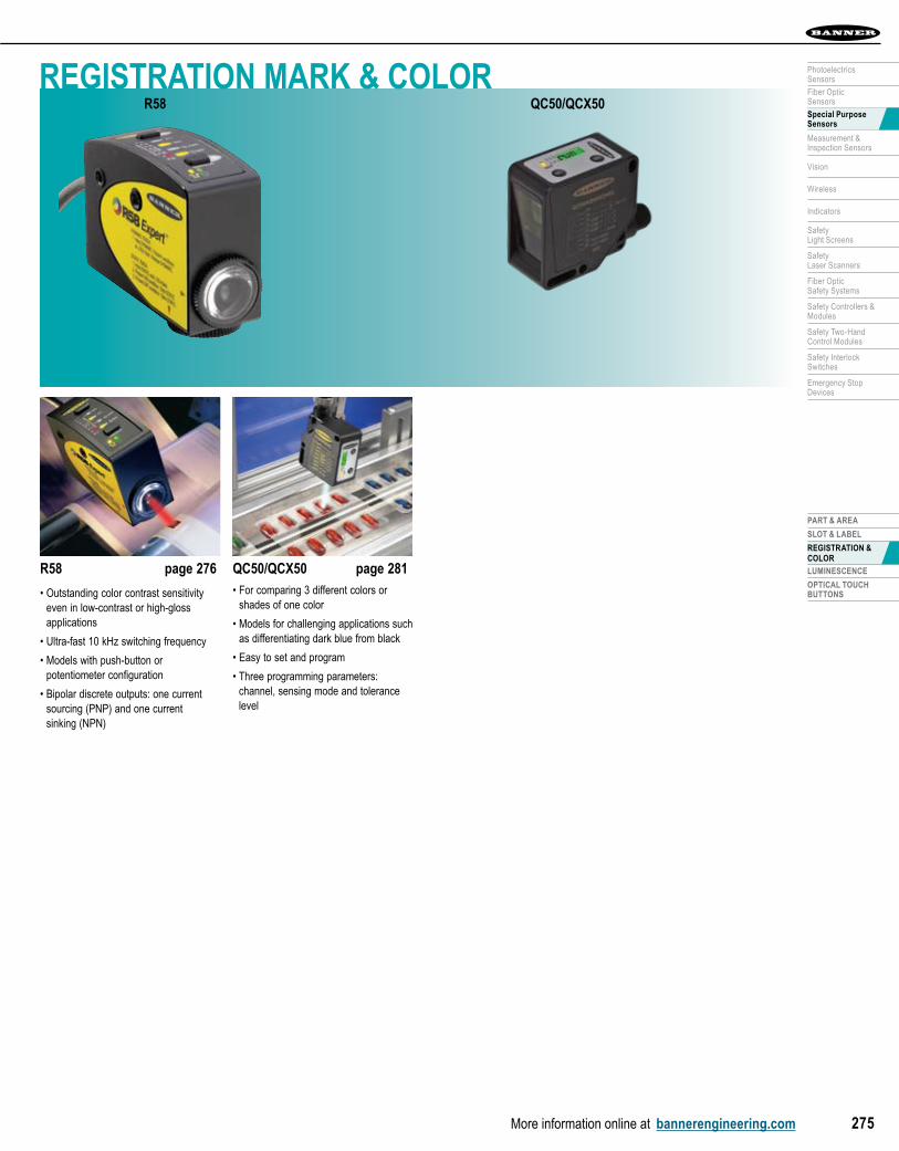
R58 page 276
• Outstanding color contrast sensitivity even in low-contrast or high-gloss applications
• Ultra-fast 10 kHz switching frequency
• Models with push-button or potentiometer configuration
• Bipolar discrete outputs: one current sourcing (PNP) and one current sinking (NPN)
QC50/QCX50 page 281• For comparing 3 different colors or
shades of one color
• Models for challenging applications such as differentiating dark blue from black
• Easy to set and program
• Three programming parameters: channel, sensing mode and tolerance level
REGISTRATION MARK & COLORQC50/QCX50R58
SEN
SOR
S
More information online at bannerengineering.com276
PART & AREA SLOT & LABEL REGISTRATION & COLOR LUMinESCEnCE OPTiCAL TOUCH BUTTOnS
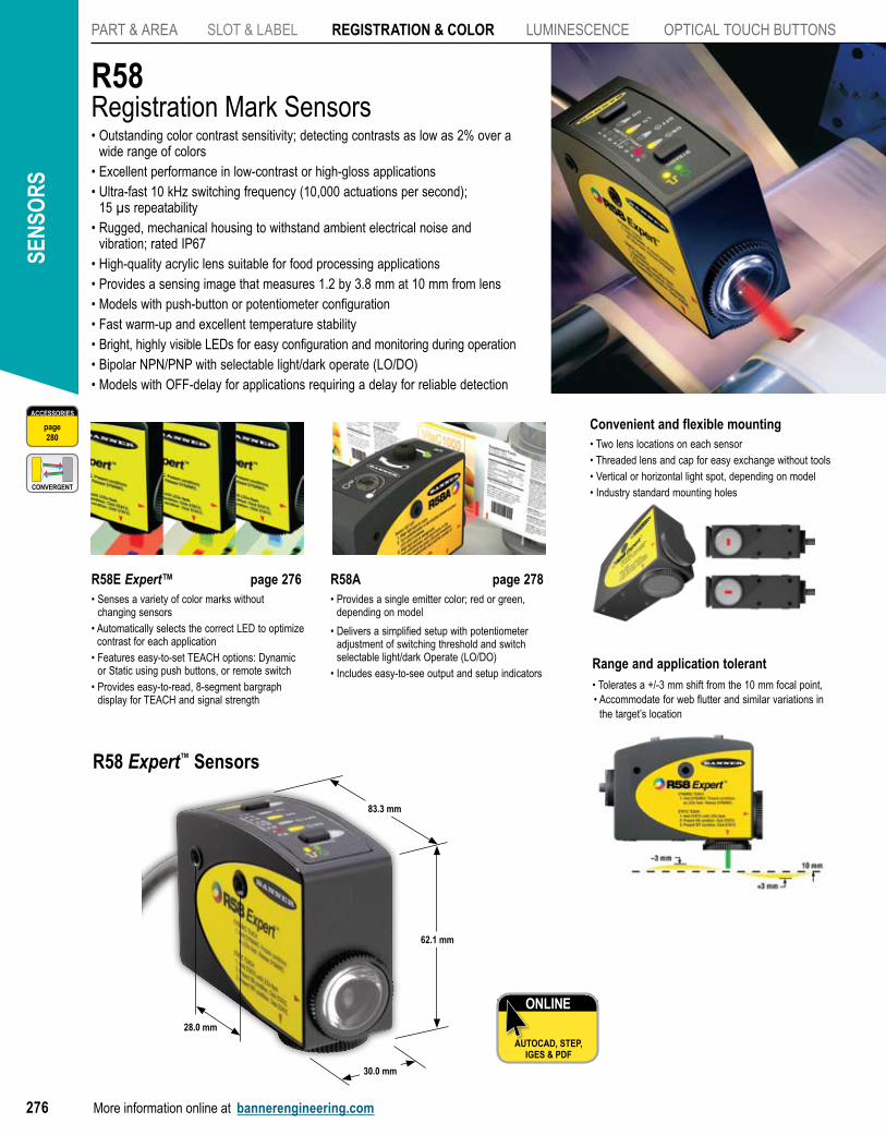
R58Registration Mark Sensors• Outstanding color contrast sensitivity; detecting contrasts as low as 2% over a
wide range of colors• Excellent performance in low-contrast or high-gloss applications• Ultra-fast 10 kHz switching frequency (10,000 actuations per second);
15 µs repeatability• Rugged, mechanical housing to withstand ambient electrical noise and
vibration; rated IP67 • High-quality acrylic lens suitable for food processing applications• Provides a sensing image that measures 1.2 by 3.8 mm at 10 mm from lens• Models with push-button or potentiometer configuration• Fast warm-up and excellent temperature stability• Bright, highly visible LEDs for easy configuration and monitoring during operation• Bipolar NPN/PNP with selectable light/dark operate (LO/DO)• Models with OFF-delay for applications requiring a delay for reliable detection
Convenient and flexible mounting • Two lens locations on each sensor• Threaded lens and cap for easy exchange without tools• Vertical or horizontal light spot, depending on model• Industry standard mounting holes
R58E Expert™ page 276• Senses a variety of color marks without
changing sensors• Automatically selects the correct LED to optimize
contrast for each application• Features easy-to-set TEACH options: Dynamic
or Static using push buttons, or remote switch• Provides easy-to-read, 8-segment bargraph
display for TEACH and signal strength
R58A page 278• Provides a single emitter color; red or green,
depending on model
• Delivers a simplified setup with potentiometer adjustment of switching threshold and switch selectable light/dark Operate (LO/DO)
• Includes easy-to-see output and setup indicatorsRange and application tolerant• Tolerates a +/-3 mm shift from the 10 mm focal point, • Accommodate for web flutter and similar variations in
the target’s location
ONLINE
AUTOCAD, STEP, IGES & PDF
83.3 mm
62.1 mm
30.0 mm
28.0 mm
CONVERGENT
CONVERGENT
R58 Expert™ Sensors
ACCESSORIES
page280
PART & AREA
SLOT & LABEL
REGISTRATION & COLOR
R58
QC50/QCX50
LUMINESCENCE
OPTICAL TOUCHBUTTONS
More information online at bannerengineering.com 277
PhotoelectricsSensors
Fiber OpticSensors
Special PurposeSensors
Measurement & Inspection Sensors
Vision
Wireless
Indicators
Safety Light Screens
Safety Laser Scanners
Fiber OpticSafety Systems
Safety Controllers & Modules
Safety Two-Hand Control Modules
Safety Interlock Switches
Emergency Stop Devices
ACCESSORIES
page280
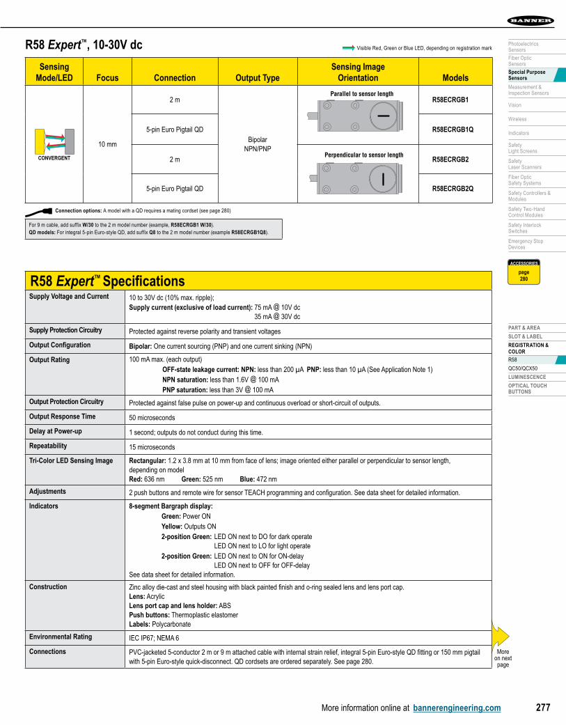
R58 Expert™, 10-30V dc
Sensing Mode/LED Focus Connection Output Type
Sensing ImageOrientation Models
CONVERGENT
CONVERGENT
10 mm
2 m
Bipolar NPN/PNP
Parallel to sensor length
Perpendicular to sensor length
R58ECRGB1
5-pin Euro Pigtail QD R58ECRGB1Q
2 m
Parallel to sensor length
Perpendicular to sensor lengthR58ECRGB2
5-pin Euro Pigtail QD R58ECRGB2Q
Visible Red, Green or Blue LED, depending on registration mark
R58 Expert™ SpecificationsSupply Voltage and Current 10 to 30V dc (10% max. ripple);
Supply current (exclusive of load current): 75 mA @ 10V dc 35 mA @ 30V dc
Supply Protection Circuitry Protected against reverse polarity and transient voltages
Output Configuration Bipolar: One current sourcing (PNP) and one current sinking (NPN)
Output Rating 100 mA max. (each output) OFF-state leakage current: NPN: less than 200 µA PNP: less than 10 µA (See Application Note 1) NPN saturation: less than 1.6V @ 100 mA PNP saturation: less than 3V @ 100 mA
Output Protection Circuitry Protected against false pulse on power-up and continuous overload or short-circuit of outputs.
Output Response Time 50 microseconds
Delay at Power-up 1 second; outputs do not conduct during this time.
Repeatability 15 microseconds
Tri-Color LED Sensing Image Rectangular: 1.2 x 3.8 mm at 10 mm from face of lens; image oriented either parallel or perpendicular to sensor length, depending on modelRed: 636 nm Green: 525 nm Blue: 472 nm
Adjustments 2 push buttons and remote wire for sensor TEACH programming and configuration. See data sheet for detailed information.
Indicators 8-segment Bargraph display: Green: Power ON Yellow: Outputs ON 2-position Green: LED ON next to DO for dark operate LED ON next to LO for light operate 2-position Green: LED ON next to ON for ON-delay LED ON next to OFF for OFF-delaySee data sheet for detailed information.
Construction Zinc alloy die-cast and steel housing with black painted finish and o-ring sealed lens and lens port cap. Lens: Acrylic Lens port cap and lens holder: ABS Push buttons: Thermoplastic elastomer Labels: Polycarbonate
Environmental Rating IEC IP67; NEMA 6
Connections PVC-jacketed 5-conductor 2 m or 9 m attached cable with internal strain relief, integral 5-pin Euro-style QD fitting or 150 mm pigtail with 5-pin Euro-style quick-disconnect. QD cordsets are ordered separately. See page 280.
Moreon next page
Connection options: A model with a QD requires a mating cordset (see page 280)
For 9 m cable, add suffix W/30 to the 2 m model number (example, R58ECRGB1 W/30).QD models: For integral 5-pin Euro-style QD, add suffix Q8 to the 2 m model number (example R58ECRGB1Q8).
SEN
SOR
S
More information online at bannerengineering.com278
PART & AREA SLOT & LABEL REGISTRATION & COLOR LUMinESCEnCE OPTiCAL TOUCH BUTTOnS
ACCESSORIES
page280
ONLINE
AUTOCAD, STEP, IGES & PDF
R58 Expert™ SpecificationsOperating Conditions Temperature: -10° to +55° C Relative humidity: 90% at 50° C (non-condensing)
Storage temperature: -20° to +80° C
Vibration and Mechanical Shock
All models meet IEC 68-2-6 and IEC 68-2-27 testing criteria.
Application Notes 1. NPN OFF-state leakage current is < 200 μA for load impedances > 3kΩ or optically isolated loads. For load current of 100 mA, leakage is < 1% of load current.2. Do not mount the sensor directly perpendicular to shiny surfaces; position it at approximately 15 angle in relation to the sensing target.3. Minimize web or product “flutter” whenever possible to maximize sensing reliability. Position sensor near a roller if possible.
Certification
Hookup Diagrams DC08 (p. 717)
(cont’d)
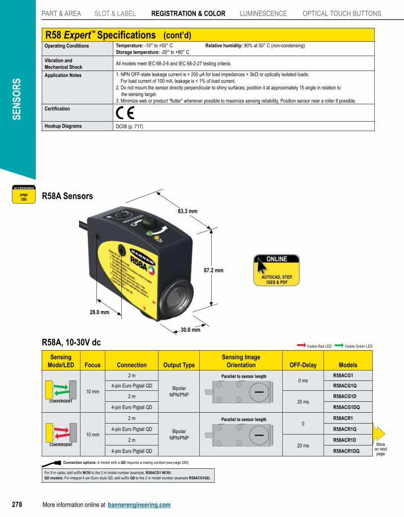
R58A, 10-30V dc
Sensing Mode/LED Focus Connection Output Type
Sensing ImageOrientation OFF-Delay Models
CONVERGENTCONVERGENT
10 mm
2 m
Bipolar NPN/PNP
Parallel to sensor length
Perpendicular to sensor length
0 msR58ACG1
4-pin Euro Pigtail QD R58ACG1Q
2 m20 ms
R58ACG1D
4-pin Euro Pigtail QD R58ACG1DQ
CONVERGENT
10 mm
2 m
Bipolar NPN/PNP
Parallel to sensor length
Perpendicular to sensor length
0R58ACR1
4-pin Euro Pigtail QD R58ACR1Q
2 m20 ms
R58ACR1D
4-pin Euro Pigtail QD R58ACR1DQMore
on next page
R58A Sensors
67.2 mm
30.0 mm
83.3 mm
28.0 mm
Visible Red LED Visible Green LED
Connection options: A model with a QD requires a mating cordset (see page 280)
For 9 m cable, add suffix W/30 to the 2 m model number (example, R58ACG1 W/30).QD models: For integral 4-pin Euro-style QD, add suffix Q8 to the 2 m model number (example R58ACG1Q8).
PART & AREA
SLOT & LABEL
REGISTRATION & COLOR
R58
QC50/QCX50
LUMINESCENCE
OPTICAL TOUCHBUTTONS
More information online at bannerengineering.com 279
PhotoelectricsSensors
Fiber OpticSensors
Special PurposeSensors
Measurement & Inspection Sensors
Vision
Wireless
Indicators
Safety Light Screens
Safety Laser Scanners
Fiber OpticSafety Systems
Safety Controllers & Modules
Safety Two-Hand Control Modules
Safety Interlock Switches
Emergency Stop Devices
ACCESSORIES
page280
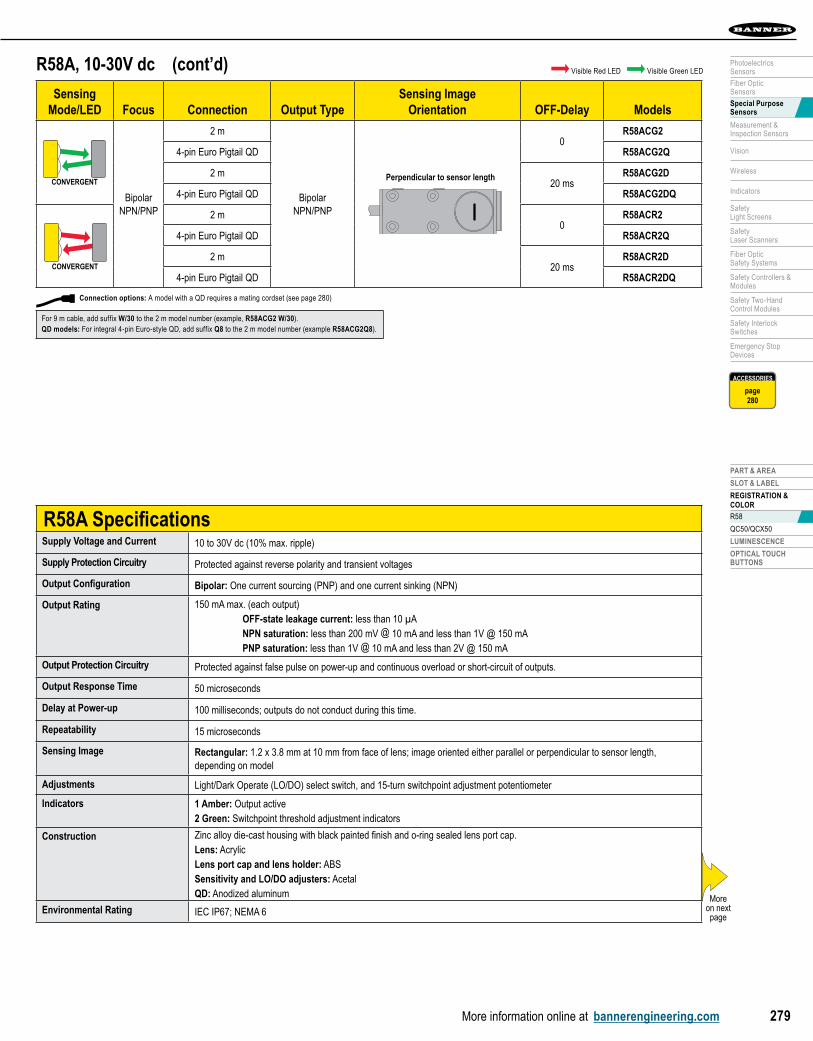
R58A, 10-30V dc
Sensing Mode/LED Focus Connection Output Type
Sensing ImageOrientation OFF-Delay Models
CONVERGENTCONVERGENT
Bipolar NPN/PNP
2 m
Bipolar NPN/PNP
Parallel to sensor length
Perpendicular to sensor length
0R58ACG2
4-pin Euro Pigtail QD R58ACG2Q
2 m20 ms
R58ACG2D
4-pin Euro Pigtail QD R58ACG2DQ
CONVERGENT
2 m0
R58ACR2
4-pin Euro Pigtail QD R58ACR2Q
2 m20 ms
R58ACR2D
4-pin Euro Pigtail QD R58ACR2DQ
(cont’d)
Connection options: A model with a QD requires a mating cordset (see page 280)
For 9 m cable, add suffix W/30 to the 2 m model number (example, R58ACG2 W/30).QD models: For integral 4-pin Euro-style QD, add suffix Q8 to the 2 m model number (example R58ACG2Q8).
R58A SpecificationsSupply Voltage and Current 10 to 30V dc (10% max. ripple)
Supply Protection Circuitry Protected against reverse polarity and transient voltages
Output Configuration Bipolar: One current sourcing (PNP) and one current sinking (NPN)
Output Rating 150 mA max. (each output) OFF-state leakage current: less than 10 µA NPN saturation: less than 200 mV @ 10 mA and less than 1V @ 150 mA PNP saturation: less than 1V @ 10 mA and less than 2V @ 150 mA
Output Protection Circuitry Protected against false pulse on power-up and continuous overload or short-circuit of outputs.
Output Response Time 50 microseconds
Delay at Power-up 100 milliseconds; outputs do not conduct during this time.
Repeatability 15 microseconds
Sensing Image Rectangular: 1.2 x 3.8 mm at 10 mm from face of lens; image oriented either parallel or perpendicular to sensor length, depending on model
Adjustments Light/Dark Operate (LO/DO) select switch, and 15-turn switchpoint adjustment potentiometer
Indicators 1 Amber: Output active2 Green: Switchpoint threshold adjustment indicators
Construction Zinc alloy die-cast housing with black painted finish and o-ring sealed lens port cap. Lens: Acrylic Lens port cap and lens holder: ABS Sensitivity and LO/DO adjusters: Acetal QD: Anodized aluminum
Environmental Rating IEC IP67; NEMA 6More
on next page
Visible Red LED Visible Green LED
SEN
SOR
S
More information online at bannerengineering.com280
PART & AREA SLOT & LABEL REGISTRATION & COLOR LUMinESCEnCE OPTiCAL TOUCH BUTTOnS
BracketsR58E/R58A
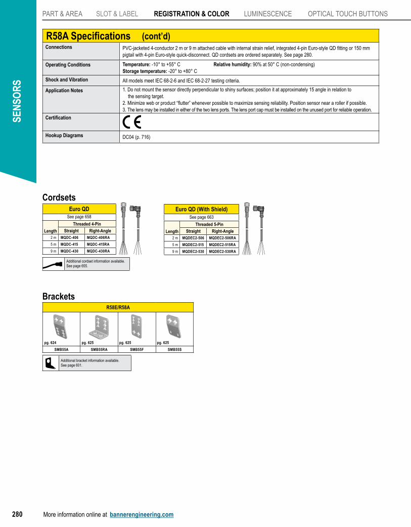
SMB55A SMB55RA SMB55F SMB55S
pg. 624 pg. 625 pg. 625 pg. 625
Additional bracket information available.See page 601.
R58A SpecificationsConnections PVC-jacketed 4-conductor 2 m or 9 m attached cable with internal strain relief, integrated 4-pin Euro-style QD fitting or 150 mm
pigtail with 4-pin Euro-style quick-disconnect. QD cordsets are ordered separately. See page 280.
Operating Conditions Temperature: -10° to +55° C Relative humidity: 90% at 50° C (non-condensing)Storage temperature: -20° to +80° C
Shock and Vibration All models meet IEC 68-2-6 and IEC 68-2-27 testing criteria.
Application Notes 1. Do not mount the sensor directly perpendicular to shiny surfaces; position it at approximately 15 angle in relation to the sensing target.2. Minimize web or product “flutter” whenever possible to maximize sensing reliability. Position sensor near a roller if possible.3. The lens may be installed in either of the two lens ports. The lens port cap must be installed on the unused port for reliable operation.
Certification
Hookup Diagrams DC04 (p. 716)
Euro QDSee page 658
Length
Threaded 4-Pin
Straight Right-Angle2 m MQDC-406 MQDC-406RA
5 m MQDC-415 MQDC-415RA
9 m MQDC-430 MQDC-430RA
Cordsets
Additional cordset information available.See page 655.
(cont’d)
Euro QD (With Shield)See page 663
Length
Threaded 5-Pin
Straight Right-Angle2 m MQDEC2-506 MQDEC2-506RA
5 m MQDEC2-515 MQDEC2-515RA
9 m MQDEC2-530 MQDEC2-530RA
PART & AREA
SLOT & LABEL
REGISTRATION & COLOR
R58
QC50/QCX50
LUMINESCENCE
OPTICAL TOUCHBUTTONS
More information online at bannerengineering.com 281
PhotoelectricsSensors
Fiber OpticSensors
Special PurposeSensors
Measurement & Inspection Sensors
Vision
Wireless
Indicators
Safety Light Screens
Safety Laser Scanners
Fiber OpticSafety Systems
Safety Controllers & Modules
Safety Two-Hand Control Modules
Safety Interlock Switches
Emergency Stop Devices
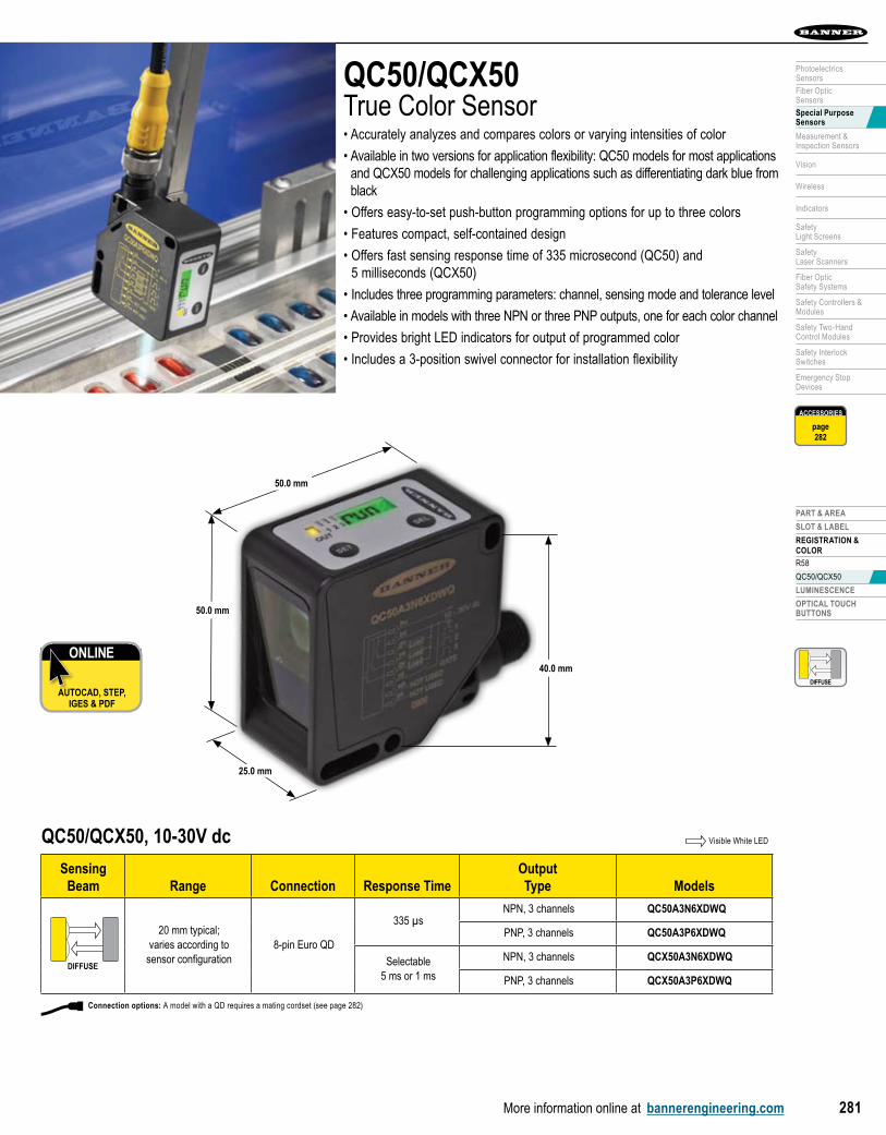
QC50/QCX50True Color Sensor• Accurately analyzes and compares colors or varying intensities of color
• Available in two versions for application flexibility: QC50 models for most applications and QCX50 models for challenging applications such as differentiating dark blue from black
• Offers easy-to-set push-button programming options for up to three colors
• Features compact, self-contained design
• Offers fast sensing response time of 335 microsecond (QC50) and 5 milliseconds (QCX50)
• Includes three programming parameters: channel, sensing mode and tolerance level
• Available in models with three NPN or three PNP outputs, one for each color channel
• Provides bright LED indicators for output of programmed color
• Includes a 3-position swivel connector for installation flexibility
ONLINE
AUTOCAD, STEP, IGES & PDF
QC50/QCX50, 10-30V dc
Sensing Beam Range Connection Response Time
OutputType Models
DIFFUSEDIFFUSE
20 mm typical; varies according to
sensor configuration8-pin Euro QD
335 µsNPN, 3 channels QC50A3N6XDWQ
PNP, 3 channels QC50A3P6XDWQ
Selectable 5 ms or 1 ms
NPN, 3 channels QCX50A3N6XDWQ
PNP, 3 channels QCX50A3P6XDWQ
Visible White LED
DIFFUSEDIFFUSE
Connection options: A model with a QD requires a mating cordset (see page 282)
ACCESSORIES
page282
50.0 mm
25.0 mm
40.0 mm
50.0 mm
SEN
SOR
S
More information online at bannerengineering.com282
PART & AREA SLOT & LABEL REGISTRATION & COLOR LUMinESCEnCE OPTiCAL TOUCH BUTTOnS
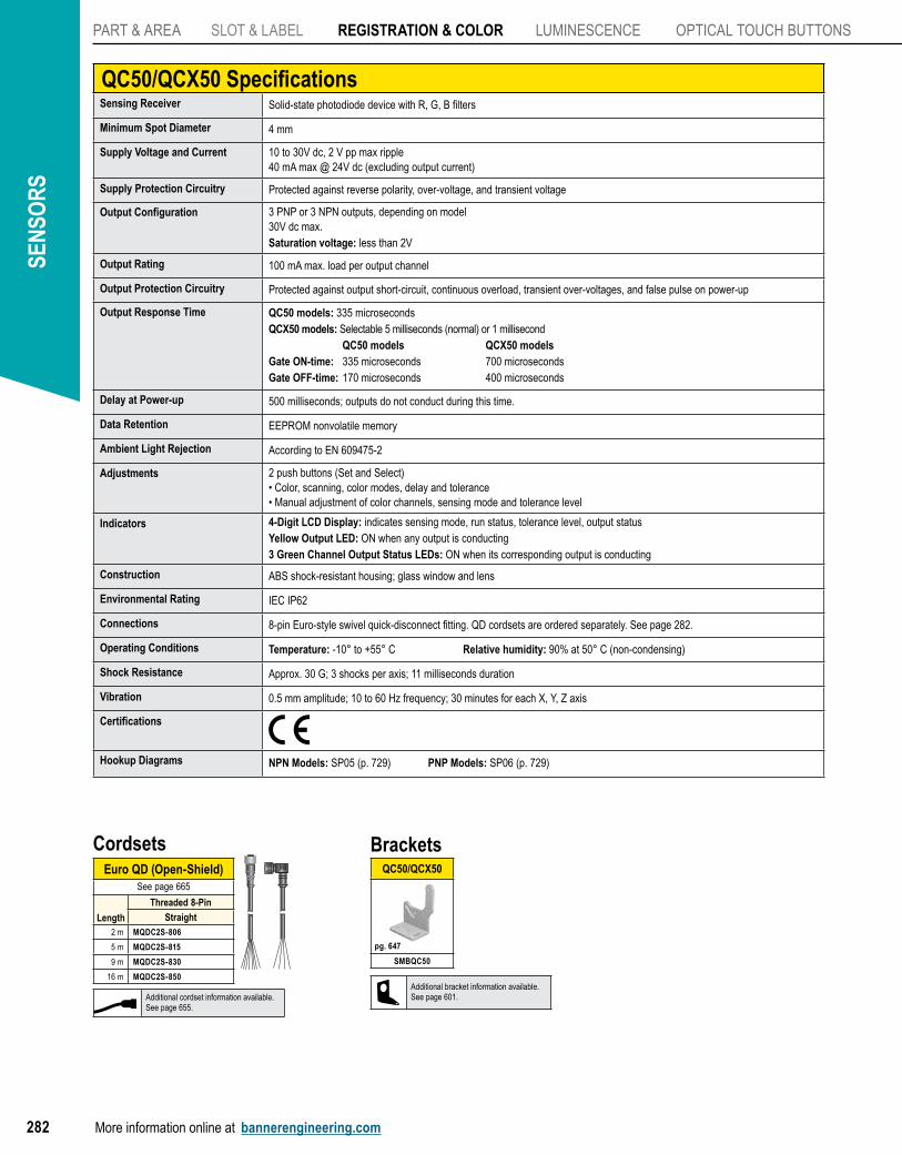
QC50/QCX50 SpecificationsSensing Receiver Solid-state photodiode device with R, G, B filters
Minimum Spot Diameter 4 mm
Supply Voltage and Current 10 to 30V dc, 2 V pp max ripple40 mA max @ 24V dc (excluding output current)
Supply Protection Circuitry Protected against reverse polarity, over-voltage, and transient voltage
Output Configuration 3 PNP or 3 NPN outputs, depending on model30V dc max.Saturation voltage: less than 2V
Output Rating 100 mA max. load per output channel
Output Protection Circuitry Protected against output short-circuit, continuous overload, transient over-voltages, and false pulse on power-up
Output Response Time QC50 models: 335 microseconds QCX50 models: Selectable 5 milliseconds (normal) or 1 millisecond QC50 models QCX50 modelsGate ON-time: 335 microseconds 700 microseconds Gate OFF-time: 170 microseconds 400 microseconds
Delay at Power-up 500 milliseconds; outputs do not conduct during this time.
Data Retention EEPROM nonvolatile memory
Ambient Light Rejection According to EN 609475-2
Adjustments 2 push buttons (Set and Select) • Color, scanning, color modes, delay and tolerance• Manual adjustment of color channels, sensing mode and tolerance level
Indicators 4-Digit LCD Display: indicates sensing mode, run status, tolerance level, output statusYellow Output LED: ON when any output is conducting3 Green Channel Output Status LEDs: ON when its corresponding output is conducting
Construction ABS shock-resistant housing; glass window and lens
Environmental Rating IEC IP62
Connections 8-pin Euro-style swivel quick-disconnect fitting. QD cordsets are ordered separately. See page 282.
Operating Conditions Temperature: -10° to +55° C Relative humidity: 90% at 50° C (non-condensing)
Shock Resistance Approx. 30 G; 3 shocks per axis; 11 milliseconds duration
Vibration 0.5 mm amplitude; 10 to 60 Hz frequency; 30 minutes for each X, Y, Z axis
Certifications
Hookup Diagrams NPN Models: SP05 (p. 729) PNP Models: SP06 (p. 729)
BracketsQC50/QCX50
SMBQC50
pg. 647
Euro QD (Open-Shield)See page 665
Length
Threaded 8-Pin
Straight2 m MQDC2S-806
5 m MQDC2S-815
9 m MQDC2S-830
16 m MQDC2S-850
Cordsets
Additional cordset information available.See page 655.
Additional bracket information available.See page 601.
PART & AREA
SLOT & LABEL
REGISTRATION & COLOR
LUMINESCENCE
OPTICAL TOUCHBUTTONS
More information online at bannerengineering.com 283
PhotoelectricsSensors
Fiber OpticSensors
Special PurposeSensors
Measurement & Inspection Sensors
Vision
Wireless
Indicators
Safety Light Screens
Safety Laser Scanners
Fiber OpticSafety Systems
Safety Controllers & Modules
Safety Two-Hand Control Modules
Safety Interlock Switches
Emergency Stop Devices
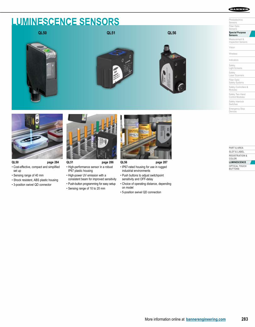
QL50 page 284• Cost-effective, compact and simplified
set up• Sensing range of 40 mm• Shock resistent, ABS plastic housing• 3-position swivel QD connector
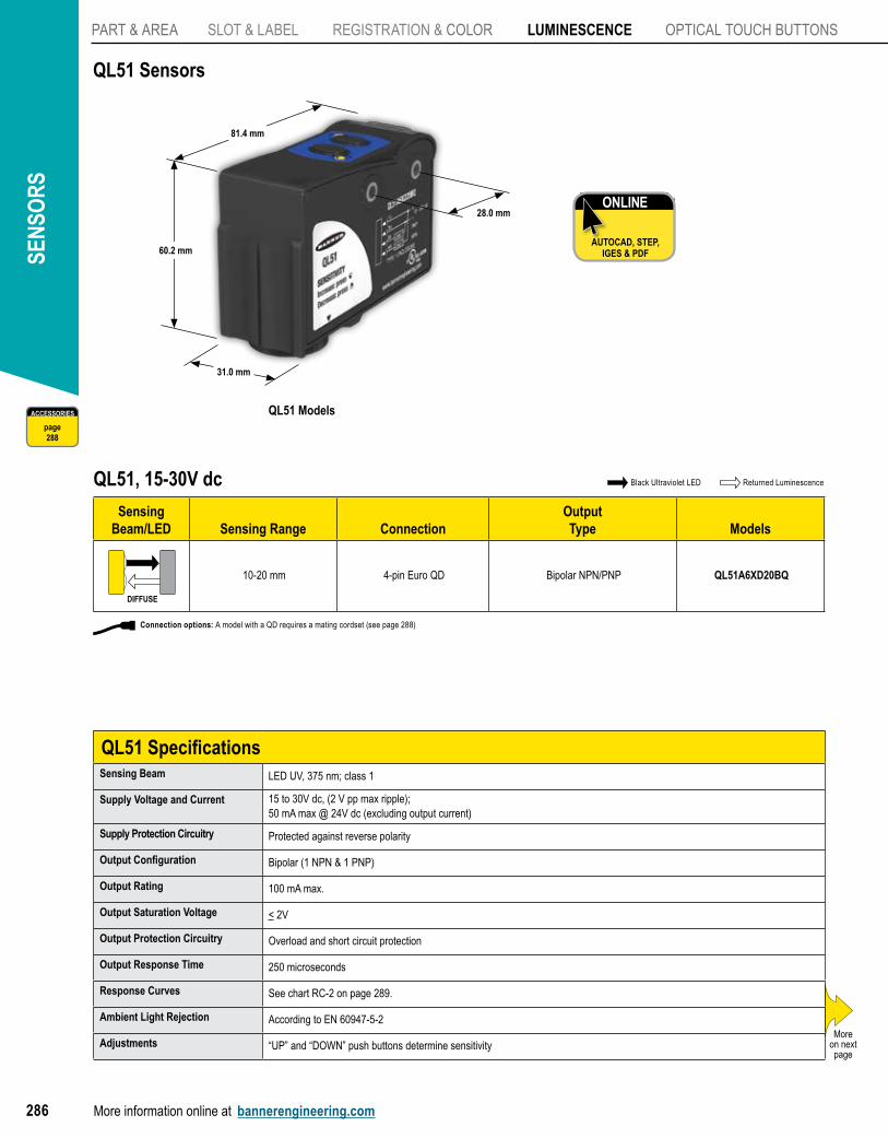
QL51 page 286• High-performance sensor in a robust
IP67 plastic housing• High-power UV emission with a
consistent beam for improved sensitivity• Push-button programming for easy setup• Sensing range of 10 to 20 mm
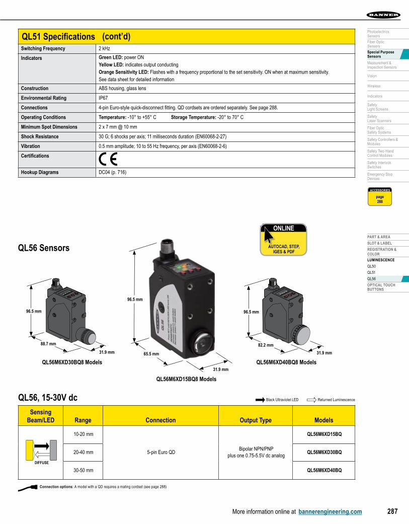
QL56 page 287• IP67-rated housing for use in rugged
industrial environments• Push buttons to adjust switchpoint
sensitivity and OFF-delay• Choice of operating distance, depending
on model• 5-position swivel QD connection
LUMINESCENCE SENSORSQL50 QL51 QL56
SEN
SOR
S
More information online at bannerengineering.com284
PART & AREA SLOT & LABEL REgiSTRATiOn & COLOR LUMINESCENCE OPTiCAL TOUCH BUTTOnS
DIFFUSED
QL50 Models page 284
QL51 Models 286
QL56 Models 287
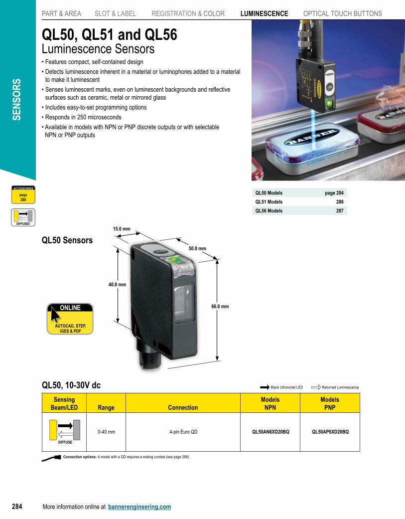
QL50, QL51 and QL56Luminescence Sensors• Features compact, self-contained design
• Detects luminescence inherent in a material or luminophores added to a material to make it luminescent
• Senses luminescent marks, even on luminescent backgrounds and reflective surfaces such as ceramic, metal or mirrored glass
• Includes easy-to-set programming options
• Responds in 250 microseconds
• Available in models with NPN or PNP discrete outputs or with selectable NPN or PNP outputs
QL50, 10-30V dc
Sensing Beam/LED Range Connection
ModelsNPN
ModelsPNP
DIFFUSE
0-40 mm 4-pin Euro QD QL50AN6XD20BQ QL50AP6XD20BQ
ONLINE
AUTOCAD, STEP, IGES & PDF
Black Ultraviolet LED Returned Luminescence
ACCESSORIES
page288
QL50 Sensors50.0 mm
66.0 mm
15.0 mm
40.0 mm
Connection options: A model with a QD requires a mating cordset (see page 288)
PART & AREA
SLOT & LABEL
REGISTRATION & COLOR
LUMINESCENCE
QL50
QL51
QL56
OPTICAL TOUCHBUTTONS
More information online at bannerengineering.com 285
PhotoelectricsSensors
Fiber OpticSensors
Special PurposeSensors
Measurement & Inspection Sensors
Vision
Wireless
Indicators
Safety Light Screens
Safety Laser Scanners
Fiber OpticSafety Systems
Safety Controllers & Modules
Safety Two-Hand Control Modules
Safety Interlock Switches
Emergency Stop Devices
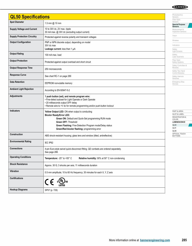
QL50 SpecificationsSpot Diameter 1.5 mm @ 10 mm
Supply Voltage and Current 10 to 30V dc, 2V max. ripple30 mA max. @ 30V dc (excluding output current)
Supply Protection Circuitry Protected against reverse polarity and transient voltages
Output Configuration PNP or NPN discrete output, depending on model30V dc maxLeakage current: less than 1 µA
Output Rating 100 mA max. load
Output Protection Protected against output overload and short circuit
Output Response Time 250 microseconds
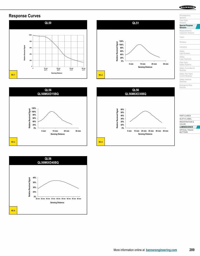
Response Curve See chart RC-1 on page 289
Data Retention EEPROM nonvolatile memory
Ambient Light Rejection According to EN 60947-5-2
Adjustments 1 push button (set), and remote program wire: • Fine-detect autoset for Light Operate or Dark Operate• 20 milliseconds output OFF-delay• Remote wire to +V dc for remote programming and/or push-button lockout
Indicators Yellow Output LED: ON when output is conductingBicolor Ready/Error LED: Green ON: Default and Quick-Set programming RUN mode Green OFF: Threshold Green Flashing: Fine-Detection Program mode/Delay status Green/Red bicolor flashing: programming error
Construction ABS shock-resistant housing; glass lens and window (tilted, antireflective)
Environmental Rating IEC IP62
Connections 4-pin Euro-style swivel quick-disconnect fitting. QD cordsets are ordered separately. See page 288.
Operating Conditions Temperature: -25° to +55° C Relative humidity: 90% at 50° C non-condensing
Shock Resistance Approx. 30 G; 3 shocks per axis; 11 milliseconds duration
Vibration 0.5 mm amplitude; 10 to 60 Hz frequency; 30 minutes for each X, Y, Z axis
Certifications
Hookup Diagrams SP07 (p. 729)
SEN
SOR
S
More information online at bannerengineering.com286
PART & AREA SLOT & LABEL REgiSTRATiOn & COLOR LUMINESCENCE OPTiCAL TOUCH BUTTOnS
QL51, 15-30V dc Black Ultraviolet LED Returned Luminescence
Sensing Beam/LED Sensing Range Connection
OutputType Models
DIFFUSE
10-20 mm 4-pin Euro QD Bipolar NPN/PNP QL51A6XD20BQ
QL51 SpecificationsSensing Beam LED UV, 375 nm; class 1
Supply Voltage and Current 15 to 30V dc, (2 V pp max ripple);50 mA max @ 24V dc (excluding output current)
Supply Protection Circuitry Protected against reverse polarity
Output Configuration Bipolar (1 NPN & 1 PNP)
Output Rating 100 mA max.
Output Saturation Voltage < 2V
Output Protection Circuitry Overload and short circuit protection
Output Response Time 250 microseconds
Response Curves See chart RC-2 on page 289.
Ambient Light Rejection According to EN 60947-5-2
Adjustments “UP” and “DOWN” push buttons determine sensitivity
QL51 Sensors
ONLINE
AUTOCAD, STEP, IGES & PDF
Moreon next page
QL51 Models
31.0 mm
60.2 mm
81.4 mm
28.0 mm
ACCESSORIES
page288
Connection options: A model with a QD requires a mating cordset (see page 288)
PART & AREA
SLOT & LABEL
REGISTRATION & COLOR
LUMINESCENCE
QL50
QL51
QL56
OPTICAL TOUCHBUTTONS
More information online at bannerengineering.com 287
PhotoelectricsSensors
Fiber OpticSensors
Special PurposeSensors
Measurement & Inspection Sensors
Vision
Wireless
Indicators
Safety Light Screens
Safety Laser Scanners
Fiber OpticSafety Systems
Safety Controllers & Modules
Safety Two-Hand Control Modules
Safety Interlock Switches
Emergency Stop Devices
ACCESSORIES
page288
QL51 SpecificationsSwitching Frequency 2 kHz
Indicators Green LED: power ONYellow LED: indicates output conductingOrange Sensitivity LED: Flashes with a frequency proportional to the set sensitivity. ON when at maximum sensitivity.See data sheet for detailed information
Construction ABS housing, glass lens
Environmental Rating IP67
Connections 4-pin Euro-style quick-disconnect fitting. QD cordsets are ordered separately. See page 288.
Operating Conditions Temperature: -10° to +55° C Storage Temperature: -20° to 70° C
Minimum Spot Dimensions 2 x 7 mm @ 10 mm
Shock Resistance 30 G; 6 shocks per axis; 11 milliseconds duration (EN60068-2-27)
Vibration 0.5 mm amplitude; 10 to 55 Hz frequency, per axis (EN60068-2-6)
Certifications
Hookup Diagrams DC04 (p. 716)
(cont’d)
QL56 Sensors
ONLINE
AUTOCAD, STEP, IGES & PDF
QL56, 15-30V dc
Sensing Beam/LED Range Connection Output Type Models
DIFFUSE
10-20 mm
5-pin Euro QDBipolar NPN/PNP
plus one 0.75-5.5V dc analog
QL56M6XD15BQ
20-40 mm QL56M6XD30BQ
30-50 mm QL56M6XD40BQ
Black Ultraviolet LED Returned Luminescence
96.5 mm
65.5 mm
31.9 mm
QL56M6XD15BQ8 Models
QL56M6XD30BQ8 Models QL56M6XD40BQ8 Models
96.5 mm
88.7 mm
31.9 mm
96.5 mm
82.2 mm
31.9 mm
Connection options: A model with a QD requires a mating cordset (see page 288)
SEN
SOR
S
More information online at bannerengineering.com288
PART & AREA SLOT & LABEL REgiSTRATiOn & COLOR LUMINESCENCE OPTiCAL TOUCH BUTTOnS
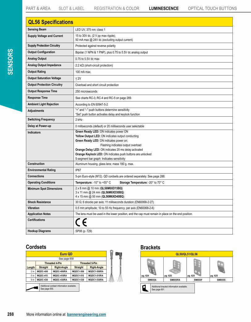
QL56 SpecificationsSensing Beam LED UV, 375 nm; class 1
Supply Voltage and Current 15 to 30V dc, (2 V pp max ripple);50 mA max @ 24V dc (excluding output current)
Supply Protection Circuitry Protected against reverse polarity
Output Configuration Bipolar (1 NPN & 1 PNP), plus 0.75 to 5.5V dc analog output
Analog Output 0.75 to 5.5V dc max
Analog Output Impedance 2.2 kΩ (short-circuit protection)
Output Rating 100 mA max.
Output Saturation Voltage < 2V
Output Protection Circuitry Overload and short circuit protection
Output Response Time 250 microseconds
Response Time See charts RC-3, RC-4 and RC-5 on page 289.
Ambient Light Rejection According to EN 60947-5-2
Adjustments “+” and “–” push buttons determine sensitivity“Set” push button activates delay and keylock function
Switching Frequency 2 kHz
Delay at Power-up 0 milliseconds (default) or 20 milliseconds user selectable
Indicators Green Ready LED: ON indicates power ONYellow Output LED: ON indicates output conductingGreen Ready LED: ON indicates power on; Flashing indicates output overloadOrange Delay LED: ON indicates 20 ms delay activatedOrange Keylock LED: ON indicates push buttons are unlocked5-segment bar graph: Indicates sensitivity
Construction Aluminum housing, glass lens; mass 180 g. max.
Environmental Rating IP67
Connections 5-pin Euro-style (M12). QD cordsets are ordered separately. See page 288.
Operating Conditions Temperature: -10° to +55° C Storage Temperature: -20° to 70° C
Minimum Spot Dimensions 2 x 8 mm @ 10 mm (QL56M6XD15BQ)3 x 11 mm @ 24 mm (QL56M6XD30BQ)4 x 15 mm @ 50 mm (QL56M6XD40BQ)
Shock Resistance 30 G; 6 shocks per axis; 11 milliseconds duration (EN60068-2-27)
Vibration 0.5 mm amplitude; 10 to 55 Hz frequency; per axis (EN60068-2-6)
Application Notes The lens must be used in the lower position, and the cap must remain in place on the end position.
Certifications
Hookup Diagrams SP08 (p. 729)
BracketsQL50/QL51/QL56
SMB55A SMB55RA SMB55F SMB55S
pg. 624 pg. 625 pg. 625 pg. 625
Additional bracket information available.See page 601.
Euro QDSee page 658
Length
Threaded 4-Pin Threaded 5-Pin
Straight Right-Angle Straight Right-Angle2 m MQDC-406 MQDC-406RA MQDC1-506 MQDC1-506RA
5 m MQDC-415 MQDC-415RA MQDC1-515 MQDC1-515RA
9 m MQDC-430 MQDC-430RA MQDC1-530 MQDC1-530RA
Cordsets
Additional cordset information available.See page 655.
PART & AREA
SLOT & LABEL
REGISTRATION & COLOR
LUMINESCENCE
OPTICAL TOUCHBUTTONS
More information online at bannerengineering.com 289
PhotoelectricsSensors
Fiber OpticSensors
Special PurposeSensors
Measurement & Inspection Sensors
Vision
Wireless
Indicators
Safety Light Screens
Safety Laser Scanners
Fiber OpticSafety Systems
Safety Controllers & Modules
Safety Two-Hand Control Modules
Safety Interlock Switches
Emergency Stop Devices
Response Curves
QL50
QL56QL56M6XD15BQ
120%
100%
80%
60%
60%
20%
0%5 mm 15 mm 25 mm 35 mm
Sensing Distance
Rel
ativ
e R
ecei
ved
Sign
al
QL56QL56M6XD40BQ
40%
30%
30%
25%
0%20 mm 25 mm 30 mm 35 mm 40 mm 45 mm 50 mm 55 mm 60 mm
Sensing Distance
Rel
ativ
e R
ecei
ved
Sign
al
QL56QL56M6XD30BQ
60%
50%
40%
30%
20%
20%
0%5 mm 15 mm 25 mm 35 mm 45 mm 55 mm
Sensing Distance
Rel
ativ
e R
ecei
ved
Sign
al
RC-1
RC-3
RC-5
RC-4
QL51
120%
100%
80%
60%
60%
20%
0%5 mm 15 mm 25 mm 35 mm
Sensing Distance
Rel
ativ
e R
ecei
ved
Sign
al
RC-2
Rel
ativ
e R
ecei
ved
Sign
al
Sensing Distance
00 10 mm
(0.4")20 mm(0.8")
30 mm(1.2")
40 mm(1.6")
20%
40%
60%
80%
100%
SEN
SOR
S
More information online at bannerengineering.com290
PART & AREA SLOT & LABEL REgiSTRATiOn & COLOR LUMinESCEnCE OPTICAL TOUCH BUTTONS
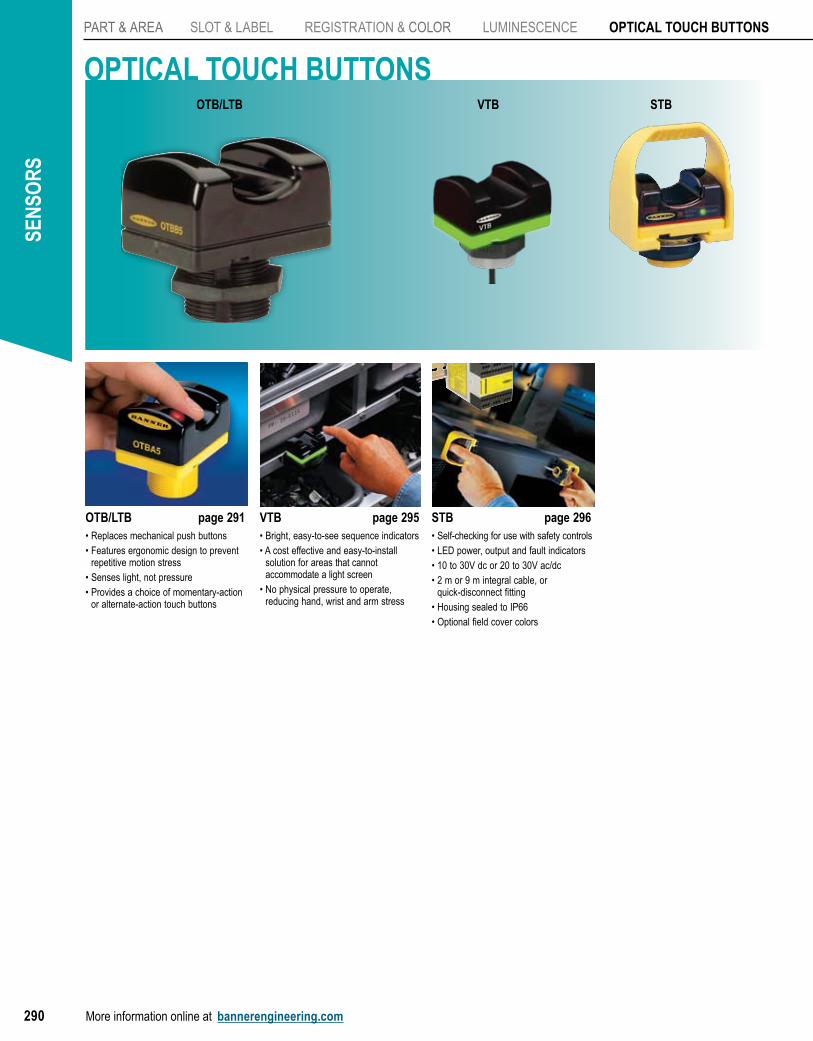
OTB/LTB page 291• Replaces mechanical push buttons• Features ergonomic design to prevent
repetitive motion stress• Senses light, not pressure• Provides a choice of momentary-action
or alternate-action touch buttons
VTB page 295• Bright, easy-to-see sequence indicators• A cost effective and easy-to-install
solution for areas that cannot accommodate a light screen
• No physical pressure to operate, reducing hand, wrist and arm stress
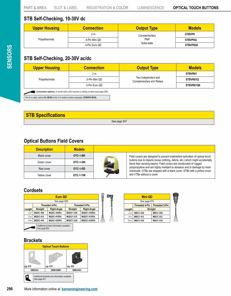
STB page 296• Self-checking for use with safety controls• LED power, output and fault indicators• 10 to 30V dc or 20 to 30V ac/dc• 2 m or 9 m integral cable, or
quick-disconnect fitting• Housing sealed to IP66• Optional field cover colors
OPTICAL TOUCH BUTTONSOTB/LTB VTB STB
PART & AREA
SLOT & LABEL
REGISTRATION & COLOR
LUMINESCENCE
OPTICAL TOUCHBUTTONS
OTB/LTB
VTB
STB
More information online at bannerengineering.com 291
PhotoelectricsSensors
Fiber OpticSensors
Special PurposeSensors
Measurement & Inspection Sensors
Vision
Wireless
Indicators
Safety Light Screens
Safety Laser Scanners
Fiber OpticSafety Systems
Safety Controllers & Modules
Safety Two-Hand Control Modules
Safety Interlock Switches
Emergency Stop Devices
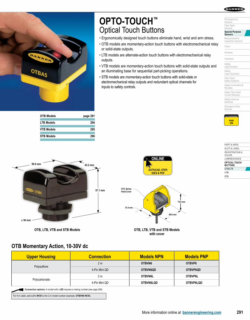
OTC SeriesField Cover
51.0 mm
69.0 mm
74.0 mm
OTB, LTB, VTB and STB Models with cover
OPTO-TOUCH™
Optical Touch Buttons• Ergonomically designed touch buttons eliminate hand, wrist and arm stress.
• OTB models are momentary-action touch buttons with electromechanical relay or solid-state outputs.
• LTB models are alternate-action touch buttons with electromechanical relay outputs.
• VTB models are momentary-action touch buttons with solid-state outputs and an illuminating base for sequential part-picking operations.
• STB models are momentary-action touch buttons with solid-state or electromechanical relay outputs and redundant optical channels for inputs to safety controls.
OTB Momentary Action, 10-30V dc
Upper Housing Connection Models NPN Models PNP
Polysulfone2 m OTBVN6 OTBVP6
4-Pin Mini QD OTBVN6QD OTBVP6QD
Polycarbonate2 m OTBVN6L OTBVP6L
4-Pin Mini QD OTBVN6LQD OTBVP6LQD
ONLINE
AUTOCAD, STEP, IGES & PDF
OTB, LTB, VTB and STB Models
43.2 mm
57.1 mm
59.9 mm
ø 30 mm
OTB Models page 291
LTB Models 294
VTB Models 295
STB Models 296
ACCESSORIES
page296
Connection options: A model with a QD requires a mating cordset (see page 296)
For 9 m cable, add suffix W/30 to the 2 m model number (example, OTBVN6 W/30).
SEN
SOR
S
More information online at bannerengineering.com292
PART & AREA SLOT & LABEL REgiSTRATiOn & COLOR LUMinESCEnCE OPTICAL TOUCH BUTTONS
ACCESSORIES
page296
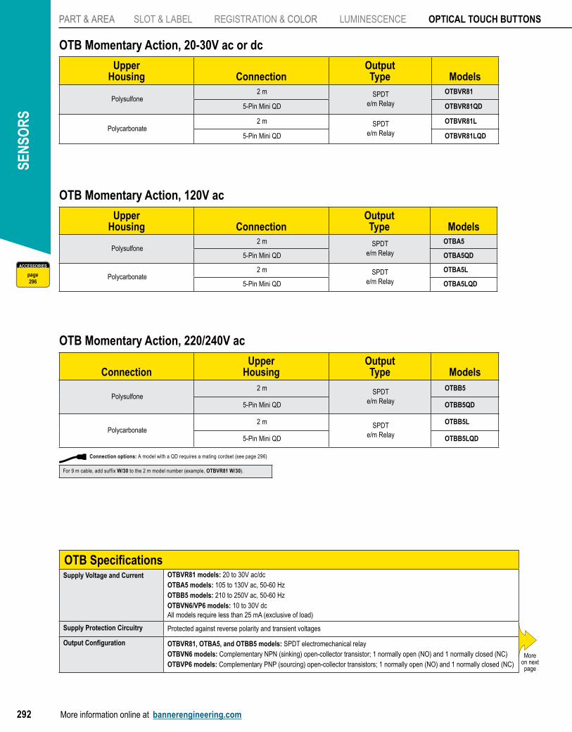
OTB Momentary Action, 220/240V ac
ConnectionUpper
HousingOutputType Models
Polysulfone2 m SPDT
e/m Relay
OTBB5
5-Pin Mini QD OTBB5QD
Polycarbonate2 m SPDT
e/m Relay
OTBB5L
5-Pin Mini QD OTBB5LQD
OTB Momentary Action, 120V ac
UpperHousing Connection
OutputType Models
Polysulfone2 m SPDT
e/m Relay
OTBA5
5-Pin Mini QD OTBA5QD
Polycarbonate2 m SPDT
e/m Relay
OTBA5L
5-Pin Mini QD OTBA5LQD
OTB Momentary Action, 20-30V ac or dc
UpperHousing Connection
OutputType Models
Polysulfone2 m SPDT
e/m Relay
OTBVR81
5-Pin Mini QD OTBVR81QD
Polycarbonate2 m SPDT
e/m Relay
OTBVR81L
5-Pin Mini QD OTBVR81LQD
OTB SpecificationsSupply Voltage and Current OTBVR81 models: 20 to 30V ac/dc
OTBA5 models: 105 to 130V ac, 50-60 HzOTBB5 models: 210 to 250V ac, 50-60 HzOTBVN6/VP6 models: 10 to 30V dcAll models require less than 25 mA (exclusive of load)
Supply Protection Circuitry Protected against reverse polarity and transient voltages
Output Configuration OTBVR81, OTBA5, and OTBB5 models: SPDT electromechanical relayOTBVN6 models: Complementary NPN (sinking) open-collector transistor; 1 normally open (NO) and 1 normally closed (NC)OTBVP6 models: Complementary PNP (sourcing) open-collector transistors; 1 normally open (NO) and 1 normally closed (NC)
Moreon next page
Connection options: A model with a QD requires a mating cordset (see page 296)
For 9 m cable, add suffix W/30 to the 2 m model number (example, OTBVR81 W/30).
PART & AREA
SLOT & LABEL
REGISTRATION & COLOR
LUMINESCENCE
OPTICAL TOUCHBUTTONS
OTB/LTB
VTB
STB
More information online at bannerengineering.com 293
PhotoelectricsSensors
Fiber OpticSensors
Special PurposeSensors
Measurement & Inspection Sensors
Vision
Wireless
Indicators
Safety Light Screens
Safety Laser Scanners
Fiber OpticSafety Systems
Safety Controllers & Modules
Safety Two-Hand Control Modules
Safety Interlock Switches
Emergency Stop Devices
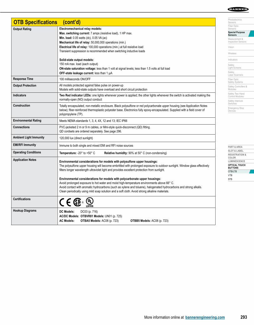
OTB SpecificationsOutput Rating Electromechanical relay models:
Max. switching current: 7 amps (resistive load), 1 HP max.Min. load: 0.05 watts (dc), 0.05 VA (ac)Mechanical life of relay: 50,000,000 operations (min.)Electrical life of relay: 100,000 operations (min.) at full resistive loadTransient suppression is recommended when switching inductive loads
Solid-state output models:150 mA max. load (each output)ON-state saturation voltage: less than 1 volt at signal levels; less than 1.5 volts at full loadOFF-state leakage current: less than 1 µA
Response Time 100 milliseconds ON/OFF
Output Protection All models protected against false pulse on power-upModels with solid-state outputs have overload and short circuit protection
Indicators Two Red indicator LEDs: one lights whenever power is applied; the other lights whenever the switch is activated making the normally-open (NO) output conduct
Construction Totally encapsulated, non-metallic enclosure. Black polysulfone or red polycarbonate upper housing (see Application Notes below); fiber-reinforced thermoplastic polyester base. Electronics fully epoxy-encapsulated. Supplied with a field cover of polypropylene (TP).
Environmental Rating Meets NEMA standards 1, 3, 4, 4X, 12 and 13; IEC IP66
Connections PVC-jacketed 2 m or 9 m cables, or Mini-style quick-disconnect (QD) fitting.QD cordsets are ordered separately. See page 296.
Ambient Light Immunity 120,000 lux (direct sunlight)
EMI/RFI Immunity Immune to both single and mixed EMI and RFI noise sources
Operating Conditions Temperature: -20° to +50° C Relative humidity: 90% at 50° C (non-condensing)
Application Notes Environmental considerations for models with polysulfone upper housings:The polysulfone upper housing will become embrittled with prolonged exposure to outdoor sunlight. Window glass effectively filters longer wavelength ultraviolet light and provides excellent protection from sunlight.
Environmental considerations for models with polycarbonate upper housings:Avoid prolonged exposure to hot water and moist high-temperature environments above 66° C. Avoid contact with aromatic hydrocarbons (such as xylene and toluene), halogenated hydrocarbons and strong alkalis. Clean periodically using mild soap solution and a soft cloth. Avoid strong alkaline materials.
Certifications
Hookup Diagrams DC Models: DC03 (p. 716)AC/DC Models: OTBVR81 Models: UN01 (p. 725)AC Models: OTBA5 Models: AC08 (p. 723) OTBB5 Models: AC08 (p. 723)
(cont’d)
SEN
SOR
S
More information online at bannerengineering.com294
PART & AREA SLOT & LABEL REgiSTRATiOn & COLOR LUMinESCEnCE OPTICAL TOUCH BUTTONS
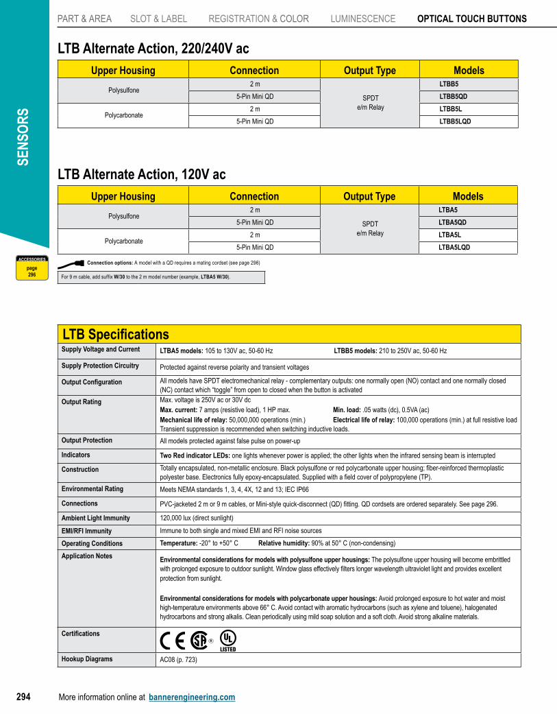
LTB Alternate Action, 120V acUpper Housing Connection Output Type Models
Polysulfone2 m
SPDTe/m Relay
LTBA5
5-Pin Mini QD LTBA5QD
Polycarbonate2 m LTBA5L
5-Pin Mini QD LTBA5LQD
LTB SpecificationsSupply Voltage and Current LTBA5 models: 105 to 130V ac, 50-60 Hz LTBB5 models: 210 to 250V ac, 50-60 Hz
Supply Protection Circuitry Protected against reverse polarity and transient voltages
Output Configuration All models have SPDT electromechanical relay - complementary outputs: one normally open (NO) contact and one normally closed (NC) contact which “toggle” from open to closed when the button is activated
Output Rating Max. voltage is 250V ac or 30V dcMax. current: 7 amps (resistive load), 1 HP max. Min. load: .05 watts (dc), 0.5VA (ac)Mechanical life of relay: 50,000,000 operations (min.) Electrical life of relay: 100,000 operations (min.) at full resistive loadTransient suppression is recommended when switching inductive loads.
Output Protection All models protected against false pulse on power-up
Indicators Two Red indicator LEDs: one lights whenever power is applied; the other lights when the infrared sensing beam is interrupted
Construction Totally encapsulated, non-metallic enclosure. Black polysulfone or red polycarbonate upper housing; fiber-reinforced thermoplastic polyester base. Electronics fully epoxy-encapsulated. Supplied with a field cover of polypropylene (TP).
Environmental Rating Meets NEMA standards 1, 3, 4, 4X, 12 and 13; IEC IP66
Connections PVC-jacketed 2 m or 9 m cables, or Mini-style quick-disconnect (QD) fitting. QD cordsets are ordered separately. See page 296.
Ambient Light Immunity 120,000 lux (direct sunlight)
EMI/RFI Immunity Immune to both single and mixed EMI and RFI noise sources
Operating Conditions Temperature: -20° to +50° C Relative humidity: 90% at 50° C (non-condensing)
Application Notes Environmental considerations for models with polysulfone upper housings: The polysulfone upper housing will become embrittled with prolonged exposure to outdoor sunlight. Window glass effectively filters longer wavelength ultraviolet light and provides excellent protection from sunlight.
Environmental considerations for models with polycarbonate upper housings: Avoid prolonged exposure to hot water and moist high-temperature environments above 66° C. Avoid contact with aromatic hydrocarbons (such as xylene and toluene), halogenated hydrocarbons and strong alkalis. Clean periodically using mild soap solution and a soft cloth. Avoid strong alkaline materials.
Certifications
Hookup Diagrams AC08 (p. 723)
LTB Alternate Action, 220/240V acUpper Housing Connection Output Type Models
Polysulfone2 m
SPDTe/m Relay
LTBB5
5-Pin Mini QD LTBB5QD
Polycarbonate2 m LTBB5L
5-Pin Mini QD LTBB5LQD
Connection options: A model with a QD requires a mating cordset (see page 296)
For 9 m cable, add suffix W/30 to the 2 m model number (example, LTBA5 W/30).
ACCESSORIES
page296
PART & AREA
SLOT & LABEL
REGISTRATION & COLOR
LUMINESCENCE
OPTICAL TOUCHBUTTONS
OTB/LTB
VTB
STB
More information online at bannerengineering.com 295
PhotoelectricsSensors
Fiber OpticSensors
Special PurposeSensors
Measurement & Inspection Sensors
Vision
Wireless
Indicators
Safety Light Screens
Safety Laser Scanners
Fiber OpticSafety Systems
Safety Controllers & Modules
Safety Two-Hand Control Modules
Safety Interlock Switches
Emergency Stop Devices
ACCESSORIES
page296
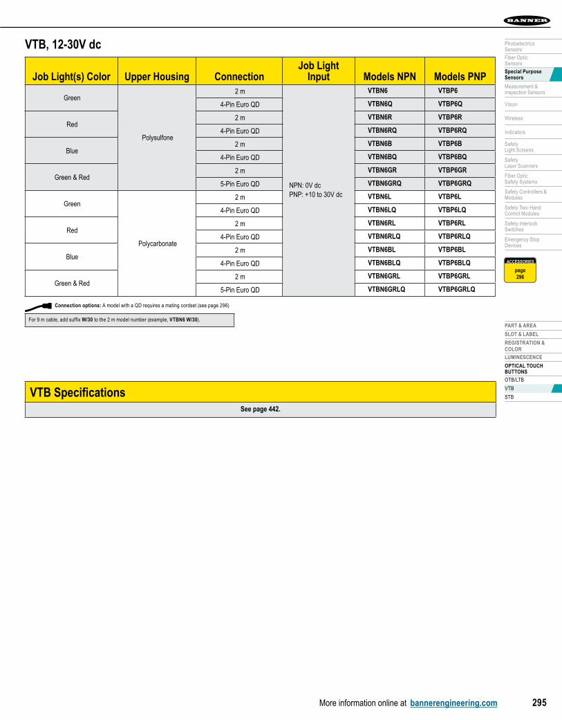
VTB, 12-30V dc
Job Light(s) Color Upper Housing ConnectionJob Light
Input Models NPN Models PNP
green
Polysulfone
2 m
NPN: 0V dcPNP: +10 to 30V dc
VTBN6 VTBP6
4-Pin Euro QD VTBN6Q VTBP6Q
Red2 m VTBN6R VTBP6R
4-Pin Euro QD VTBN6RQ VTBP6RQ
Blue2 m VTBN6B VTBP6B
4-Pin Euro QD VTBN6BQ VTBP6BQ
Green & Red2 m VTBN6GR VTBP6GR
5-Pin Euro QD VTBN6GRQ VTBP6GRQ
green
Polycarbonate
2 m VTBN6L VTBP6L
4-Pin Euro QD VTBN6LQ VTBP6LQ
Red2 m VTBN6RL VTBP6RL
4-Pin Euro QD VTBN6RLQ VTBP6RLQ
Blue2 m VTBN6BL VTBP6BL
4-Pin Euro QD VTBN6BLQ VTBP6BLQ
Green & Red2 m VTBN6GRL VTBP6GRL
5-Pin Euro QD VTBN6GRLQ VTBP6GRLQ
VTB SpecificationsSee page 442.
Connection options: A model with a QD requires a mating cordset (see page 296)
For 9 m cable, add suffix W/30 to the 2 m model number (example, VTBN6 W/30).
SEN
SOR
S
More information online at bannerengineering.com296
PART & AREA SLOT & LABEL REgiSTRATiOn & COLOR LUMinESCEnCE OPTICAL TOUCH BUTTONS
STB SpecificationsSee page 547
STB Self-Checking, 20-30V ac/dc
Upper Housing Connection Output Type Models
Polyethermide
2 mTwo Independent and
Complementary e/m Relays
STBVR81
5-Pin Mini QD STBVR81Q
5-Pin Euro QD STBVR81Q6
STB Self-Checking, 10-30V dc
Upper Housing Connection Output Type Models
Polyethermide
2 m ComplementaryPnP
Solid-state
STBVP6
4-Pin Mini QD STBVP6Q
4-Pin Euro QD STBVP6Q5
Optical Buttons Field Covers
Description Models
Black cover OTC-1-BK Field covers are designed to prevent inadvertent activation of optical touch buttons due to objects (loose clothing, debris, etc.) which might accidentally block their sensing beams. Field covers are constructed of rugged polypropylene and are highly resistant to abrasion and to damage by most chemicals. OTBs are shipped with a black cover, STBs with a yellow cover and VTBs without a cover.
Green cover OTC-1-GN
Red cover OTC-1-RD
Yellow cover OTC-1-YW
BracketsOptical Touch Buttons
SMB30A SMB30MM SMB30SC
pg. 619 pg. 619 pg. 620
Additional brackets and information available.See page 601.
Connection options: A model with a QD requires a mating cordset (see page 296)
For 9 m cable, add suffix W/30 to the 2 m model number (example, STBVP6 W/30).
Euro QDSee page 658
Length
Threaded 4-Pin Threaded 5-Pin
Straight Right-Angle Straight Right-Angle2 m MQDC-406 MQDC-406RA MQDC1-506 MQDC1-506RA
5 m MQDC-415 MQDC-415RA MQDC1-515 MQDC1-515RA
9 m MQDC-430 MQDC-430RA MQDC1-530 MQDC1-530RA
Cordsets
Additional cordset information available.See page 655.
Mini QDSee page 674
Length
Threaded 4-Pin Threaded 5-Pin
Straight2 m MBCC-406 MBCC-506
4 m MBCC-412 MBCC-512
10 m MBCC-430 MBCC-530


![Chapter 296-52 WAC - leg.wa.govleg.wa.gov/CodeReviser/WACArchive/Documents/2018/WAC 296 - 52 CHAPTER.… · (8/1/17) [ch. 296-52 wac p. 1] chapter 296-52 chapter 296-52 wac safety](https://img.pdfslide.us/doc/110x75/5e1c55c238ed802015030b5e/chapter-296-52-wac-legwa-296-52-chapter-8117-ch-296-52-wac-p-1.jpg)

![Chapter 296-19A Chapter 296-19A WAC VOCATIONAL …lawfilesext.leg.wa.gov/law/WACArchive/2012/WAC-296... · 296-19A-010 Vocational Rehabilitation [Ch. 296-19A WAC—p. 2] (11/15/11)](https://img.pdfslide.us/doc/110x75/6013de7783e2d5485a5626ed/chapter-296-19a-chapter-296-19a-wac-vocational-296-19a-010-vocational-rehabilitation.jpg)


![leg.wa.govleg.wa.gov/CodeReviser/WACArchive/Documents/2012/WAC-296-826... · (2/17/09) [Ch. 296-826 WAC—p. 1] Chapter 296-826 Chapter 296-826 WAC ANHYDROUS AMMONIA WAC 296-826-100](https://img.pdfslide.us/doc/110x75/5b2b78217f8b9ae6278b475f/legwa-21709-ch-296-826-wacp-1-chapter-296-826-chapter-296-826-wac.jpg)