Embed Size (px)
Citation preview

09/14/12 PN 96815 v.3.0
Banks Six-Gun®
Diesel TunerCompatible with Optional Banks iQ™
2001-2005 Chevy/GMC 6.6L Duramax Turbo-Diesel Pickups THIS MANUAL IS FOR USE WITH SYSTEMS
63717, 63767, 63729, 63739
Gale Banks Engineering 546 Duggan Avenue • Azusa, cA 91702 (626) 969-9600 • Fax (626) 334-1743
Product Information & Sales: (888) 635-4565customer Support: (888) 839-5600 Installation Support: (888) 839-2700
bankspower.com
©2012 Gale Banks Engineering
2 96815 v.3.0
Six-Gun® Diesel Tuner & Banks iQ® 2.0 (P/N 63729, 63739) - controls Banks diesel tuner and/or
SpeedBrake™ - Big 5” full-color touch-screen display - Interchangeable gauge display –
change screens/colors - Read & clear codes - 1⁄4, 1⁄8 mile & 0-60 performance
testing - Multi-media playback (music, video
games, pictures) - View your Microsoft® Office
documents on the go...and much more!
Six-Gun® Diesel Tuner & switch (P/N 63767, 63717, 64507) - Destroys the competition, not your
vehicle! - cleanTune® Technology - change-on-the-fly power (includes
fuel economy level) - 0-60 mph in 1/3 less distance!
- ActiveSafety® protects engine & powertrain
- Touch-screen Vehicle command center
- 1⁄4, 1⁄8 mile & 0-60 performance testing
- Multi-media playback (music, video games, pictures)
- View your Microsoft® Office documents on the go...and much more!
EconoMind® Diesel Tuner & Banks iQ® 2.0 (P/N 63727, 63728, 63737, 63738) - controls Banks diesel tuner and/or
SpeedBrake™ - Big 5” full-color touch-screen display - Interchangeable gauge display –
change screens/colors - Read & clear codes - 1⁄4, 1⁄8 mile & 0-60 performance
testing - Multi-media playback (music, video
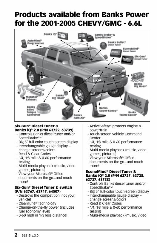
Products available from Banks Power for the 2001-2005 CHEVY/GMC - 6.6L
96815 v.3.0 3
For More Information please call (888) 635-4565or Visit us online @ www.bankspower.com
games, pictures) - View your Microsoft® Office
documents on the go...and much more!
EconoMind® Diesel Tuner & switch (P/N 63763, 63765, 63713, 63715) - Tunes pulse width, timing & fuel
pressure - cleanTune® Technology - Better fuel economy under any load - 20% faster hillclimbs, in a higher gear - Up to 19% more MPG - ActiveSafety® protects engine/
powertrain
Banks Bullet® (P/N 636516, 66517) (‘01-’04 only) - Value priced, yet loaded with
features - STOcK, TOW, SPORT power levels - EGT* & Boost gauge - Displays critical engine functions - Set temp limit & save your engine
with optional thermocouple
Ba nks iQ® 2.0 (P/N 61141, 61142) - controls Banks diesel tuner and/or
SpeedBrake™ - Big 5” full-color touch-screen display - Interchangeable gauge display –
change screens/colors - Read & clear codes - 1⁄4, 1⁄8 mile & 0-60 performance
testing - Multi-media playback (music, video
games, pictures) - View your Microsoft® Office
documents on the go...and much more!
AutoMind® Programmer (P/N 66104) - Adjust or remove the engine rev
limiter and/or top speed limiter - Speedometer calibration based on
tire size and/or gear ratio - Adjust the cooling fan activation
temperature - Adjust shift points and/or shift
firmness - Includes a fuel economy calibration - Reads and clear trouble codes - Internet updateable
Big Hoss® Bundle (P/N 47712-47729, 47737-47742) Includes: - Monster® Diesel Duals Exhaust - Banks Ram-Air® Intake System - Six-Gun® Diesel Tuner &
Banks iQ® 2.0 - Monster Muffler - BigHead® Wastegate Actuator - Techni-cooler® Intercooler System
Six-Gun® Bundle (P/N 47700-47711, 47731-47736) Includes: - Monster® Diesel Duals Exhaust - Banks Ram-Air® Intake System - Six-Gun® Diesel Tuner &
Banks iQ® 2.0 - Monster Muffler - BigHead® Wastegate Actuator
PowerPack® System (P/N 48963-48980, 48989-48994) Includes: - Monster® Diesel (Single or Duals)
Exhaust - Banks Ram-Air® Intake System - EconoMind® Diesel Tuner &
Banks iQ® 2.0 - Monster Muffler - BigHead® Wastegate Actuator - Techni-cooler® Intercooler System
Stinger® System (P/N 48950-48961, 48982-48987) Includes: - Monster® Diesel (Single or Duals)
Exhaust - Banks Ram-Air® Intake System - EconoMind® Diesel Tuner &
Banks iQ® 2.0 - Monster Muffler - BigHead® Wastegate Actuator
4 96815 v.3.0
Banks Ram-Air® Intake System (P/N 41518, 42132, 42135, 42138, 42142, 90092, 90093) - Extensively tested & validated - Increases power & fuel economy - Reduces exhaust gas temps (EGTs) &
smoke - Outflows stock & competitors up to
57% - Optional Super-Scoop® rams cold air
for more power
Banks Super-Scoop® (P/N 42168, 42169) - More Power & MPG - Forces charge of cool, pressurized
ram air into filter housing - Optimizes Ram-Air Intake efficiency
for more power
Techni-Cooler® Intercooler System (P/N 25976, 25977, 25978) - Packs cool, dense air into the
cylinders - Lower restriction for superior flow - 25% thicker core with 34% more
volume - Big boost tubes & durable cast end
tanks - cooler EGTs + more MPG &
continuous power
SpeedBrake™ (P/N 55419, 55437, 55440) (‘04-’05 only) - All-electronic design with exclusive
Speed control - User-selectable downhill speed (25-
75 mph) is automatically maintained - Basic braking function is far superior
to conventional exhaust brakes - cuts downhill speed up to 78% - Plug-&-play install; no cutting or
welding
Banks Brake® (P/N 55232, 55233, 55246, 55447) - Superior Exhaust Braking - Computer-controlled exhaust brake
maximizes braking power - cuts downhill speed up to 52%
without use of wheel brakes
- Keeps brakes cool & ready for emergencies
- Saves thousands in brake maintenance!
Monster® Diesel Duals Exhaust (P/N 48670-48675, 48942-48946) - 100% stainless, not aluminized! - Doubles the flow; virtually no
backpressure - Huge polished ob-round rolled-edge
tips - Muffler’s expansion chamber cuts
the drone - Perfect fit; no spare tire relocation
required
Monster® Exhaust (P/N 48628, 48629, 48630, 48632, 48633, 48634) - 100% stainless, not aluminized! - Improves flow up to 176%; virtually
no backpressure - Giant polished rolled-edge tip - Muffler’s expansion chamber cuts
the drone - A perfect fit
Monster® Sport Exhaust (P/N 48769, 48770, 48771, 48778) - 4” constant-diameter cat-back
exhaust system - Virtually eliminates backpressure &
nearly triples flow! - Lowers exhaust gas temps - Straight-through Monster Muffler
delivers a commanding exhaust note - 100% Stainless Steel - Easy install - 5” rolled-edge polished tip is optional - Fully compatible with the chevy/
GMc factory warranty - 5-Year Limited Warranty
Banks Billet™ Torque Converter (P/N 72510) - Triples Torque capacity - Tough enough for racing - Non-slip three-friction-element
clutch system - Triples stock’s torque capacity - Lowers trans fluid temps
96815 v.3.0 5
- Improves acceleration
BigHead® Wastegate Actuator (P/N 24396) - Quick, controlled Boost - Doubles stock’s diaphragm area &
spring pressure - Produces massive torque right from
idle - Achieves higher peak boost sooner - More mid-range muscle
Big Hoss® Intake Manifold (P/N 42733) - Pure Race capability. Part of the
Banks Racing product line; the only purpose-built cast manifolds created for a Duramax. Provides tremendous flow and uniform air distribution.
For More Information please call (888) 635-4565or Visit us online @ www.bankspower.com

6 96815 v.3.0
THIS IS A HIGH PERFORMANCE PRODUCT. USE AT YOUR OWN RISK.
Do not use this product until you have carefully read the following agreement.
This sets forth the terms and conditions for the use of this product. The installation of this product indicates that the BUYER has read and understands this agreement and accepts its terms and conditions.
Disclaimer of LiabilityGale Banks Engineering Inc., and its distributors, employees, and dealers (hereafter “SELLER”) shall in no way be responsible for the product’s proper use and service. The BUYER hereby waives all liability claims.
The BUYER acknowledges that he/she is not relying on the SELLER’s skill or judgment to select or furnish goods suitable for any particular purpose and that there are no liabilities which extended beyond the description on the face hereof and the BUYER hereby waives all remedies or liabilities, expressed or implied, arising by law or otherwise, (including without any obligations of the SELLER with respect to fitness, merchantability, and consequential damages) whether or not occasioned by the SELLER’s negligence.
The BUYER is responsible to fully understand the capability and limitations of his/her vehicle according to manufacturer specifications and agrees to hold the SELLER harmless from any damage resulting from the failure to adhere to such specifications.
The SELLER disclaims any warranty and expressly disclaims any liability for personal injury or damages. The
BUYER acknowledges and agrees that the disclaimer of any liability for personal injury is a material term for this agreement and the BUYER agrees to indemnify the SELLER and to hold the SELLER harmless from any claim related to the item of the equipment purchased. Under no circumstances will the SELLER be liable for any damages or expenses by reason of the use or sale of any such equipment.
The BUYER is responsible to obey all applicable federal, state, and local laws, statutes, and ordinances when operating his/her vehicle, and the BUYER agrees to hold SELLER harmless from any violation thereof.
The SELLER assumes no liability regarding the improper installation or misapplication of its products. It is the installer’s responsibility to check for proper installation and if in doubt, contact the manufacturer.
The BUYER is solely responsible for all warranty issues from the automotive manufacturer.
Limitation of WarrantyGale Banks Engineering Inc. (hereafter “SELLER”), gives Limited Warranty as to description, quality, merchantability, fitness for any particular purpose, productiveness, or any other matter of SELLER’s product sold herewith. The SELLER shall be in no way responsible for the product’s open use and service and the BUYER hereby waives all rights except those expressly written herein. This Warranty shall not be extended or varied except by written instrument signed by SELLER and BUYER.
Please see enclosed warranty information card, or go to www.bankspower.com/warranty, for warranty information regarding your product. All products that are in question of Warranty must be returned
96815 v.3.0 7
shipping prepaid to the SELLER and must be accompanied by a dated proof of purchase receipt. All Warranty claims are subject to approval by Gale Banks Engineering Inc.
WARNING: Below 32oF (0oC) or above 140oF (60oC), the Banks iQ may be susceptible to damage as a result of extended direct exposure to sunlight, heat or extreme cold. It is highly recommended that Banks iQ be removed from its mounting location if the vehicle will be subjected to high concentrations of sunlight, heat or cold for an extended period of time. Gale Banks Engineering is not responsible for damage to Banks iQ resulting from exposure conditions.
Under no circumstance shall the SELLER be liable for any labor charged or travel time incurred in diagnosis for defects, removal, or reinstallation of this product, or any other contingent expense.
Under no circumstances will the SELLER be liable for any damage or expenses incurred by reason of the use or sale of any such equipment.
In the event that the buyer does not agree with this agreement:
The buyer may promptly return this product, in a new and unused condition, with a dated proof-of-purchase, to the place-of-purchase within thirty (30) days from date-of-purchase for a full refund, less shipping and/or restocking fee.
The installation of this product indicates that the buyer has read and understands this agreement and accepts its terms and conditions.
Table of Contents
General Installation Practices . . . . 9
Section 1 . . . . . . . . . . . . . . . . . . . . . 11Installation of Wiring Harness, Connections and Six-Gun Diesel Tuner
Section 2 . . . . . . . . . . . . . . . . . . . . . 14Mounting and connecting the Banks iQ
Section 3 . . . . . . . . . . . . . . . . . . . . . 18Installation of the Six-Gun Selector Switch
Section 4 . . . . . . . . . . . . . . . . . . . . . 22Optional Thermocouple Installation (Required for Optional Banks iQ)
Section 5 . . . . . . . . . . . . . . . . . . . . . 24Automatic Transmission Learning
Section 6 . . . . . . . . . . . . . . . . . . . . . 25checking Engine Performance
Section 7 . . . . . . . . . . . . . . . . . . . . . 26Troubleshooting
Section 8 . . . . . . . . . . . . . . . . . . . . . 29clearing Learned Information
Section 9 . . . . . . . . . . . . . . . . . . . . . 30Placement of the Banks Power Decals
Section 10 . . . . . . . . . . . . . . . . . . . . 31Removal of the Six-Gun Diesel Tuner
8 96815 v.3.0
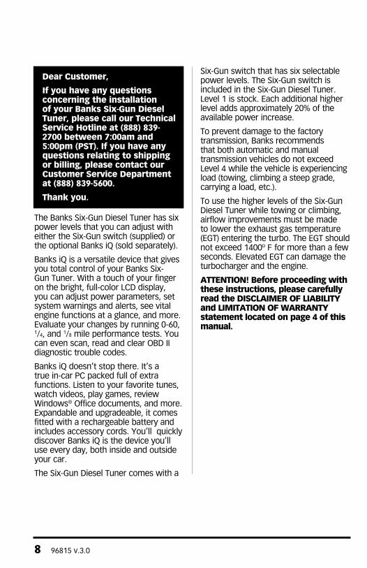
Dear Customer,
If you have any questions concerning the installation of your Banks Six-Gun Diesel Tuner, please call our Technical Service Hotline at (888) 839-2700 between 7:00am and 5:00pm (PST). If you have any questions relating to shipping or billing, please contact our Customer Service Department at (888) 839-5600.
Thank you.
The Banks Six-Gun Diesel Tuner has six power levels that you can adjust with either the Six-Gun switch (supplied) or the optional Banks iQ (sold separately).
Banks iQ is a versatile device that gives you total control of your Banks Six-Gun Tuner. With a touch of your finger on the bright, full-color LcD display, you can adjust power parameters, set system warnings and alerts, see vital engine functions at a glance, and more. Evaluate your changes by running 0-60, 1/4, and 1/8 mile performance tests. You can even scan, read and clear OBD II diagnostic trouble codes.
Banks iQ doesn’t stop there. It’s a true in-car PC packed full of extra functions. Listen to your favorite tunes, watch videos, play games, review Windows® Office documents, and more. Expandable and upgradeable, it comes fitted with a rechargeable battery and includes accessory cords. You’ll quickly discover Banks iQ is the device you’ll use every day, both inside and outside your car.
The Six-Gun Diesel Tuner comes with a
Six-Gun switch that has six selectable power levels. The Six-Gun switch is included in the Six-Gun Diesel Tuner. Level 1 is stock. Each additional higher level adds approximately 20% of the available power increase.
To prevent damage to the factory transmission, Banks recommends that both automatic and manual transmission vehicles do not exceed Level 4 while the vehicle is experiencing load (towing, climbing a steep grade, carrying a load, etc.).
To use the higher levels of the Six-Gun Diesel Tuner while towing or climbing, airflow improvements must be made to lower the exhaust gas temperature (EGT) entering the turbo. The EGT should not exceed 1400º F for more than a few seconds. Elevated EGT can damage the turbocharger and the engine.
ATTENTION! Before proceeding with these instructions, please carefully read the DISCLAIMER OF LIABILITY and LIMITATION OF WARRANTY statement located on page 4 of this manual.
96815 v.3.0 9
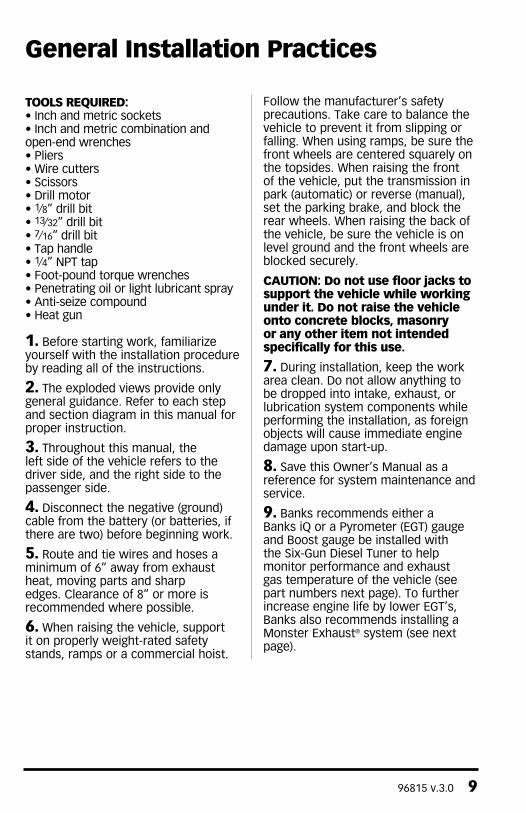
TOOLS REQUIRED:• Inch and metric sockets• Inch and metric combination and open-end wrenches• Pliers• Wire cutters• Scissors• Drill motor• 1⁄8” drill bit• 13⁄32” drill bit• 7⁄16” drill bit• Tap handle• 1⁄4” NPT tap• Foot-pound torque wrenches• Penetrating oil or light lubricant spray• Anti-seize compound• Heat gun
1. Before starting work, familiarize yourself with the installation procedure by reading all of the instructions.
2. The exploded views provide only general guidance. Refer to each step and section diagram in this manual for proper instruction.
3. Throughout this manual, the left side of the vehicle refers to the driver side, and the right side to the passenger side.
4. Disconnect the negative (ground) cable from the battery (or batteries, if there are two) before beginning work.
5. Route and tie wires and hoses a minimum of 6” away from exhaust heat, moving parts and sharp edges. clearance of 8” or more is recommended where possible.
6. When raising the vehicle, support it on properly weight-rated safety stands, ramps or a commercial hoist.
Follow the manufacturer’s safety precautions. Take care to balance the vehicle to prevent it from slipping or falling. When using ramps, be sure the front wheels are centered squarely on the topsides. When raising the front of the vehicle, put the transmission in park (automatic) or reverse (manual), set the parking brake, and block the rear wheels. When raising the back of the vehicle, be sure the vehicle is on level ground and the front wheels are blocked securely.
CAUTION: Do not use floor jacks to support the vehicle while working under it. Do not raise the vehicle onto concrete blocks, masonry or any other item not intended specifically for this use.
7. During installation, keep the work area clean. Do not allow anything to be dropped into intake, exhaust, or lubrication system components while performing the installation, as foreign objects will cause immediate engine damage upon start-up.
8. Save this Owner’s Manual as a reference for system maintenance and service.
9. Banks recommends either a Banks iQ or a Pyrometer (EGT) gauge and Boost gauge be installed with the Six-Gun Diesel Tuner to help monitor performance and exhaust gas temperature of the vehicle (see part numbers next page). To further increase engine life by lower EGT’s, Banks also recommends installing a Monster Exhaust® system (see next page).
General Installation Practices
10 96815 v.3.0
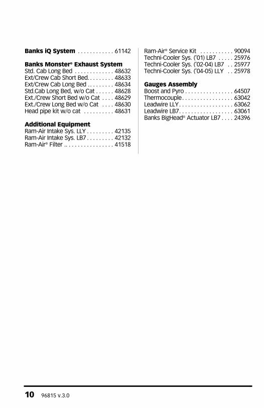
Banks iQ System . . . . . . . . . . . . 61142
Banks Monster® Exhaust SystemStd. cab Long Bed . . . . . . . . . . . . . 48632Ext/Crew Cab Short Bed. . . . . . . . . 48633Ext/Crew Cab Long Bed .. . . . . . . . 48634Std.cab Long Bed, w/o cat . . . . . . 48628Ext./Crew Short Bed w/o Cat . . . . 48629Ext./Crew Long Bed w/o Cat . . . . 48630Head pipe kit w/o cat . . . . . . . . . . 48631
Additional Equipment Ram-Air Intake Sys. LLY . . . . . . . . . 42135Ram-Air Intake Sys. LB7 . . . . . . . . . 42132Ram-Air® Filter .. . . . . . . . . . . . . . . . 41518
Ram-Air® Service Kit . . . . . . . . . . . 90094Techni-cooler Sys. (’01) LB7 . . . . . 25976Techni-cooler Sys. (’02-04) LB7 . . 25977Techni-cooler Sys. (’04-05) LLY . . 25978
Gauges Assembly Boost and Pyro . . . . . . . . . . . . . . . . 64507Thermocouple. . . . . . . . . . . . . . . . . 63042Leadwire LLY. . . . . . . . . . . . . . . . . . 63062Leadwire LB7. . . . . . . . . . . . . . . . . . 63061Banks BigHead® Actuator LB7 . . . . 24396
96815 v.3.0 11
Section 1INSTALLATION OF WIRING HARNESS, CONNECTIONS AND SIx-GUN DIESEL TUNER
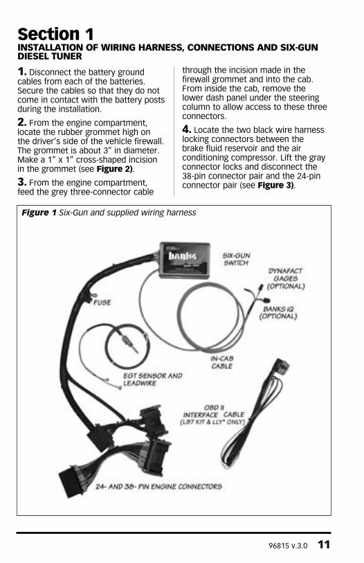
1. Disconnect the battery ground cables from each of the batteries. Secure the cables so that they do not come in contact with the battery posts during the installation.
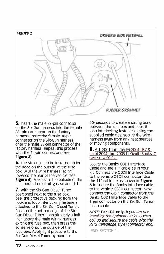
2. From the engine compartment, locate the rubber grommet high on the driver’s side of the vehicle firewall. The grommet is about 3” in diameter. Make a 1” x 1” cross-shaped incision in the grommet (see Figure 2).
3. From the engine compartment, feed the grey three-connector cable
through the incision made in the firewall grommet and into the cab. From inside the cab, remove the lower dash panel under the steering column to allow access to these three connectors.
4. Locate the two black wire harness locking connectors between the brake fluid reservoir and the air conditioning compressor. Lift the gray connector locks and disconnect the 38-pin connector pair and the 24-pin connector pair (see Figure 3).
Figure 1 Six-Gun and supplied wiring harness
12 96815 v.3.0
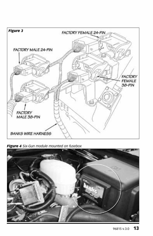
5. Insert the male 38-pin connector on the Six-Gun harness into the female 38- pin connector on the factory harness. Insert the female 38-pin connector on the Six-Gun harness onto the male 38-pin connector of the factory harness. Repeat this process with the 24-pin connectors (see Figure 3).
6. The Six-Gun is to be installed under the hood on the outside of the fuse box, with the wire harness facing towards the rear of the vehicle (see Figure 4). Make sure the outside of the fuse box is free of oil, grease and dirt.
7. With the Six-Gun Diesel Tuner positioned next to the fuse box, peel the protective backing from the hook and loop interlocking fasteners attached to the Six-Gun Diesel Tuner. Position the bottom edge of the Six-Gun Diesel Tuner approximately a half inch above the main wiring harness exiting the fuse box, then press the adhesive onto the outside of the fuse box. Apply light pressure to the Six-Gun Diesel Tuner by hand for
60- seconds to create a strong bond between the fuse box and hook & loop interlocking fasteners. Using the supplied cable ties, secure the wire harness away from any heat sources or moving components.
8. ALL 2001 thru (early) 2004 LB7 & (late) 2004 thru 2005 LLY(with Banks iQ ONLY) Vehicles:
Locate the Banks OBDII Interface cable and the 11” cable tie in your kit. connect the OBDII Interface cable to the vehicle OBDII connector. Use the 11” cable tie as shown in Figure 6 to secure the Banks interface cable to the vehicle OBDII connector. Now, connect the 6-pin connector from the Banks OBDII Interface cable to the 6-pin connector on the Six-Gun Tuner incab cable.
Note: For LB7 only, if you are not installing the optional Banks IQ then coil up and secure the cable with the RJ12 (telephone style) connector end.
-END, SEcTION 1-
Figure 2
96815 v.3.0 13
Figure 3
Figure 4 Six-Gun module mounted on fusebox
14 96815 v.3.0
All 2001 thru (early) 2004 LB7 vehicles will have an OBD II Interface cable in the kit. The OBD II Interface cable must be connected in order for the Six-Gun tuner to function.
All (late) 2004 thru 2005 LLY vehicles will require an OBD II Interface cable if connecting to an optional Banks IQ .
All Vehicles: If not installing the optional Banks iQ, skip to Section 3.
WARNING: Below 32oF (0oC) or above 140oF (60oC) the Banks iQ may be susceptible to damage as a result of extended direct exposure to sunlight, heat or extreme cold. It is highly recommended that the Banks iQ be removed from its mounting location if the vehicle will be subjected to high
concentrations of sunlight, heat or cold for an extended period of time. Gale Banks Engineering is not responsible for damage to Banks iQ resulting from exposure conditions.
CAUTION: Do not use force when working on plastic parts. Permanent damage to the part might result.
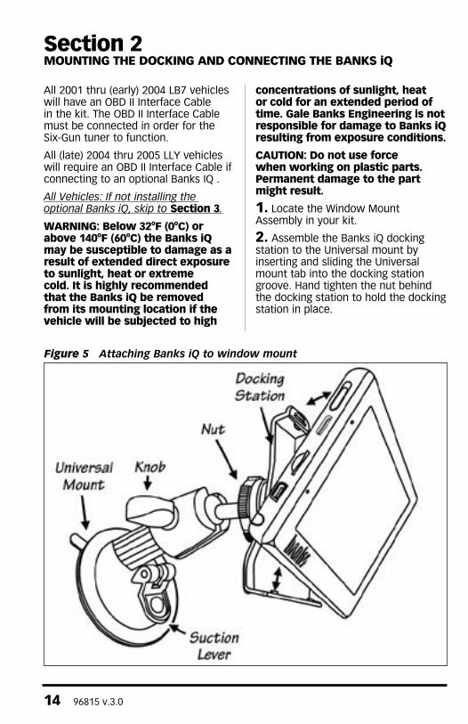
1. Locate the Window Mount Assembly in your kit.
2. Assemble the Banks iQ docking station to the Universal mount by inserting and sliding the Universal mount tab into the docking station groove. Hand tighten the nut behind the docking station to hold the docking station in place.
Section 2MOUNTING THE DOCKING AND CONNECTING THE BANKS iQ
Figure 5 Attaching Banks iQ to window mount
96815 v.3.0 15
3. Attach the window mount to your Banks iQ. See Figure 5. Align and place the two (2) lower tabs on the window mount to the corresponding slots on the bottom of Banks iQ first then snap the top of Banks iQ into place.
Note: there may be a snug fit when installing the Banks iQ into the window mount. take care not to force this process.
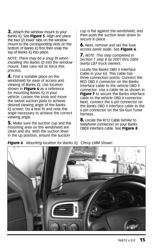
4. Find a suitable place on the windshield for ease of access and viewing of Banks iQ. Use location shown in Figure 6 as a reference for mounting Banks iQ in your vehicle. Loosen the knob and move the swivel suction plate to achieve desired viewing angle of the Banks iQ screen. Do a test fit and note the angle necessary to achieve the correct viewing angle.
5. Make sure the suction cup and the mounting area on the windshield are clean and dry. With the suction lever in the up position, ensure the suction
cup is flat against the windshield, and then push the suction lever down to secure in place.
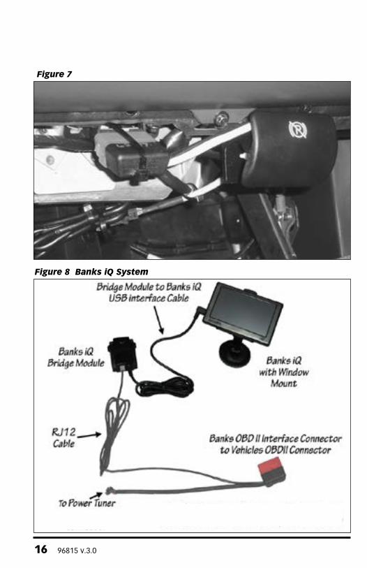
6. Next, remove and set the fuse access panel aside. See Figure 6.
7. Note: this step completed in Section 1 step 8 by 2001 thru 2004 (early) LB7 truck owners.
Locate the Banks OBD II Interface cable in your kit. This cable has three connection points. connect the RED OBD II connector on the Banks interface cable to the vehicle OBD II connector. Use a cable tie as shown in Figure 7 to secure the Banks interface cable to the vehicle OBD II connector. Next, connect the 6-pin connector on the Banks OBD II interface cable to the 6-pin connector on the Six-Gun Tuner harness.
8. Locate the RJ12 cable (similar to telephone connector) on your Banks OBDII interface cable. See Figure 8.
Figure 6 Mounting location for Banks iQ, Chevy LMM Shown
16 96815 v.3.0
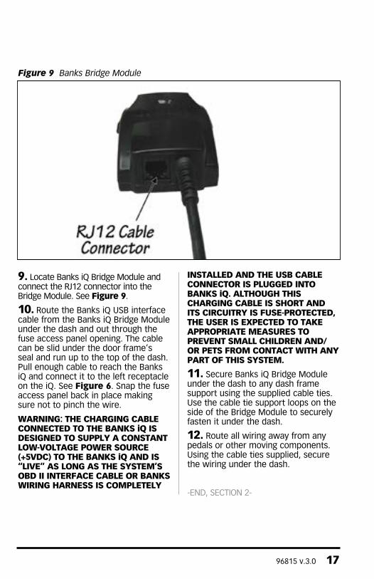
Figure 8 Banks iQ System
Figure 7
96815 v.3.0 17
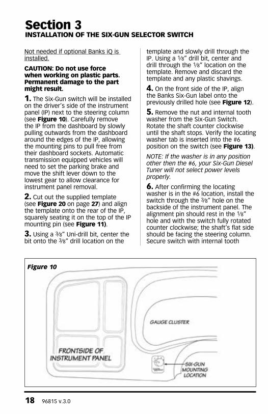
9. Locate Banks iQ Bridge Module and connect the RJ12 connector into the Bridge Module. See Figure 9.
10. Route the Banks iQ USB interface cable from the Banks iQ Bridge Module under the dash and out through the fuse access panel opening. The cable can be slid under the door frame’s seal and run up to the top of the dash. Pull enough cable to reach the Banks iQ and connect it to the left receptacle on the iQ. See Figure 6. Snap the fuse access panel back in place making sure not to pinch the wire.
WARNING: THE CHARGING CABLE CONNECTED TO THE BANKS iQ IS DESIGNED TO SUPPLY A CONSTANT LOW-VOLTAGE POWER SOURCE (+5VDC) TO THE BANKS iQ AND IS “LIVE” AS LONG AS THE SYSTEM’S OBD II INTERFACE CABLE OR BANKS WIRING HARNESS IS COMPLETELY
INSTALLED AND THE USB CABLE CONNECTOR IS PLUGGED INTO BANKS iQ. ALTHOUGH THIS CHARGING CABLE IS SHORT AND ITS CIRCUITRY IS FUSE-PROTECTED, THE USER IS ExPECTED TO TAKE APPROPRIATE MEASURES TO PREVENT SMALL CHILDREN AND/OR PETS FROM CONTACT WITH ANY PART OF THIS SYSTEM.
11. Secure Banks iQ Bridge Module under the dash to any dash frame support using the supplied cable ties. Use the cable tie support loops on the side of the Bridge Module to securely fasten it under the dash.
12. Route all wiring away from any pedals or other moving components. Using the cable ties supplied, secure the wiring under the dash.
-END, SEcTION 2-
Figure 9 Banks Bridge Module
18 96815 v.3.0
Not needed if optional Banks iQ is installed.
CAUTION: Do not use force when working on plastic parts. Permanent damage to the part might result.
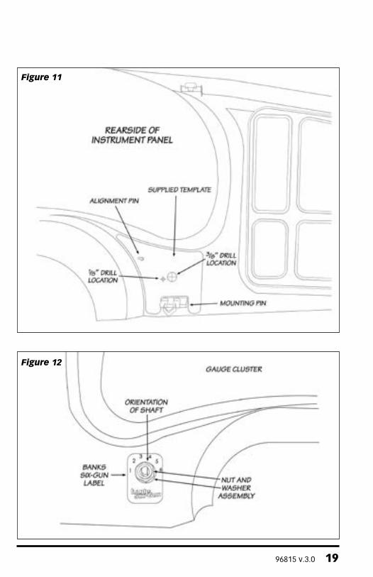
1. The Six-Gun switch will be installed on the driver’s side of the instrument panel (IP) next to the steering column (see Figure 10). carefully remove the IP from the dashboard by slowly pulling outwards from the dashboard around the edges of the IP, allowing the mounting pins to pull free from their dashboard sockets. Automatic transmission equipped vehicles will need to set the parking brake and move the shift lever down to the lowest gear to allow clearance for instrument panel removal.
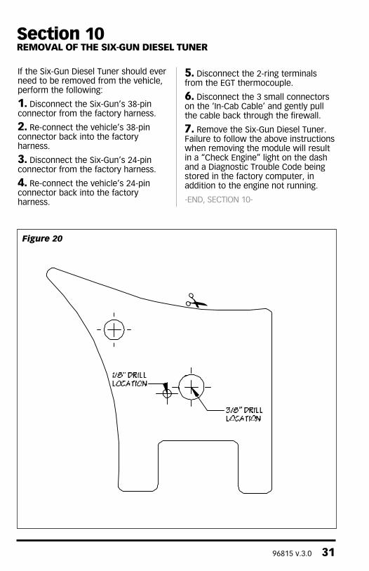
2. cut out the supplied template (see Figure 20 on page 27) and align the template onto the rear of the IP, squarely seating it on the top of the IP mounting pin (see Figure 11).
3. Using a 3⁄8” Uni-drill bit, center the bit onto the 3⁄8” drill location on the
template and slowly drill through the IP. Using a 1⁄8” drill bit, center and drill through the 1⁄8” location on the template. Remove and discard the template and any plastic shavings.
4. On the front side of the IP, align the Banks Six-Gun label onto the previously drilled hole (see Figure 12).
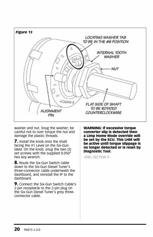
5. Remove the nut and internal tooth washer from the Six-Gun Switch. Rotate the shaft counter clockwise until the shaft stops. Verify the locating washer tab is inserted into the #6 position on the switch (see Figure 13).
Note: If the washer is in any position other then the #6, your Six-Gun Diesel tuner will not select power levels properly.
6. After confirming the locating washer is in the #6 location, install the switch through the 3⁄8” hole on the backside of the instrument panel. The alignment pin should rest in the 1⁄8” hole and with the switch fully rotated counter clockwise; the shaft’s flat side should be facing the steering column. Secure switch with internal tooth
Section 3INSTALLATION OF THE SIx-GUN SELECTOR SWITCH
Figure 10
96815 v.3.0 19
Figure 12
Figure 11
20 96815 v.3.0
washer and nut. Snug the washer; be careful not to over torque the nut and damage the plastic threads.
7. Install the knob onto the shaft facing the #1 Level on the Six-Gun label. On the knob, snug the two (2) set screws with the supplied 0.050” hex key wrench.
8. Route the Six-Gun Switch cable down to the Six-Gun Diesel Tuner’s three-connector cable underneath the dashboard, and reinstall the IP to the dashboard.
9. Connect the Six-Gun Switch Cable’s 2-pin receptacle to the 2-pin plug on the Six-Gun Diesel Tuner’s grey three-connector cable.
WARNING: if excessive torque converter slip is detected then a Limp Home Mode override will be set by the ECU. This LHM will be active until torque slippage is no longer detected or is reset by Diagnostic Tool.
-END, SEcTION 3-
Figure 13

96815 v.3.0 21
LEFT BLANK INTENTIONALLY
22 96815 v.3.0
1. The thermocouple monitors the temperature of the exhaust gases entering the turbocharger at the turbine housing. Installation requires that the exhaust manifold be drilled near the manifold outlet. It is recommended that the manifold be removed from the engine to thoroughly clean out all metal chips from drilling. If manifold is not removed from the vehicle, all chips must be removed from the manifold. This may be accomplished by using a magnet to extract the chips after drilling. The tap should be greased before use and the chips again removed with a magnet. All metal shavings must be cleaned from the manifold to avoid turbine damage.
2. To access the exhaust manifold, remove front passenger wheel well by removal of plastic retainers.
3. On the passenger side, remove the hardware retaining the turbine inlet exhaust pipe to the exhaust manifold using a 12mm, 12pt socket along with a 12mm, 12pt wrench, then remove the exhaust manifold from vehicle. Pay special attention to the orientation of the manifold outlet gasket. Retain the hardware and gaskets for re-assembly.
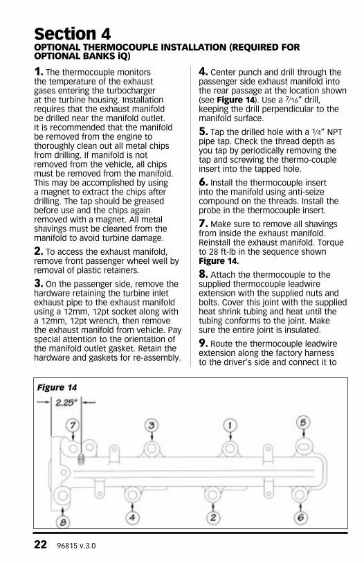
4. center punch and drill through the passenger side exhaust manifold into the rear passage at the location shown (see Figure 14). Use a 7⁄16” drill, keeping the drill perpendicular to the manifold surface.
5. Tap the drilled hole with a 1⁄4” NPT pipe tap. check the thread depth as you tap by periodically removing the tap and screwing the thermo-couple insert into the tapped hole.
6. Install the thermocouple insert into the manifold using anti-seize compound on the threads. Install the probe in the thermocouple insert.
7. Make sure to remove all shavings from inside the exhaust manifold. Reinstall the exhaust manifold. Torque to 28 ft-lb in the sequence shown Figure 14.
8. Attach the thermocouple to the supplied thermocouple leadwire extension with the supplied nuts and bolts. cover this joint with the supplied heat shrink tubing and heat until the tubing conforms to the joint. Make sure the entire joint is insulated.
9. Route the thermocouple leadwire extension along the factory harness to the driver’s side and connect it to
Section 4OPTIONAL THERMOCOUPLE INSTALLATION (REQUIRED FOR OPTIONAL BANKS iQ)
Figure 14
96815 v.3.0 23
the Six-Gun harness with the supplied nuts and bolts. cover this joint with the supplied heat shrink tubing and heat until the tubing conforms to the joint. Make sure the entire joint is insulated.
10. Reconnect the ground cables to the vehicles batteries.
Note: once the Six-Gun Diesel tuner is powered up at key-on, it will ‘learn’ that a thermocouple is installed and automatically enable the eGt limiting function. If the thermocouple is removed
after being installed and run on the vehicle, the Six-Gun Diesel tuner will assume that the sensor or connection has gone bad, and cease adding power while triggering the [2,3] diagnostic code (see trouble Shooting Section 8). to ensure that the Six-Gun Diesel tuner operates properly after removing a previously installed thermocouple, see the ‘Clearing Learned Information’ Section 9. eGt limiting will not be operational and excessive eGts may develop at higher power levels.
-END, SEcTION 4-
24 96815 v.3.0
Note: Please refer to the Banks iQ Software & Installation Kit, owners Manual for software installation and operation instruction before beginning Section 6, Automatic transmission Learning
The 6.6L Chevy Duramax Trucks equipped with the Allison 1000 5-speed automatic overdrive transmission use an adaptive shift control logic. This will require the transmission to adapt to the additional power created by the Banks Power products before it will shift properly. Failure to follow the sequence can result in damage to the transmission.
Perform the following sequence at a location where it is safe to accelerate without exceeding the posted speed limit.
1. Set Six-Gun to level one power setting, start the truck and allow the engine to reach normal operating temperature.
2. Adjust Six-Gun to level two, power setting.
3. Drive vehicle for 5 to 10 miles ensuring a complete shift cycle though each gear. (The transmission shift adaptation learning process requires 15 to 30 complete shift cycles to learn new shift program.)
4. Increase power level by one and repeat Step 3 until the desired power level is achieved.
WARNING: Take particular care not to do wide open runs in 5th gear when in Automatic transmission Learning Mode, especially if speed loader is installed.
the Allison 1000 5-speed automatic transmission will continually adapt to the power output of the engine to optimize shift quality. the transmission will quickly adapt to the power setting if the driving cycle includes regular gear changes at high loads. the transmission learning procedure will need to be repeated when switching back to the higher power settings once the transmission adapts to the lower power settings. It will be apparent when the transmission adapts to the lower settings by monitoring the feel of the gearshift. Gear changes will be noticeably harder when initially switching from a higher to lower power setting. this will soften as the transmission adapts to the new setting.
-END, SEcTION 5-
Section 5AUTOMATIC TRANSMISSION LEARNING
96815 v.3.0 25
the Six-Gun Diesel tuner requires the engine coolant temperature (eCt) to be above 110º before it will add fuel. If the optional Banks iQ or DynaFact® gauges are installed, observe the operation of the boost and pyrometer (EGT) gauge values while driving under varying conditions. Turbocharger boost pressure will increase as a function of load and engine RPM, thus the engine will produce little boost while cruising at light throttle, with maximum boost while climbing hills heavily loaded during acceleration. Note the boost level seen during hard acceleration with a given load. If performance seems to have deteriorated sometime in the future, the maximum boost figures may be compared to see if boost has dropped off. Lower boost may be caused by turbo ducting leaks, a malfunctioning wastegate or fuel injection pump, or dirty air filter. Typical maximum boost pressure settings will vary considerably with stick or automatic transmission options, year model of vehicle and altitude. Note: Before key-off, check tuner for error codes.
Use your Banks iQ or EGT gauge to monitor exhaust gas temperature (EGT) in the engine. At idle, exhaust gas temperature will be very low, perhaps only 300°F. As the engine is accelerated for higher speeds with greater loads, the EGT will rise. The highest EGT will be seen under maximum load at full throttle, such as climbing a steep grade with a heavily laden vehicle.
To avoid heat damage to various engine components it is recommended that the exhaust gases cool below 400º before the engine is shut down. Your Six-Gun Diesel Tuner is calibrated to maintain a maximum EGT of 1350°F. You may experience brief excursions slightly above 1350°F under acceleration. This is normal and EGT should return to 1350°F or below within a few seconds. If you find that EGT remains high for any length of time, check for boost leaks or a dirty air filter.
-END, SEcTION 6-
Section 6CHECKING ENGINE PERFORMANCE
26 96815 v.3.0
Six-Gun Troubleshooting Using The Banks iQ
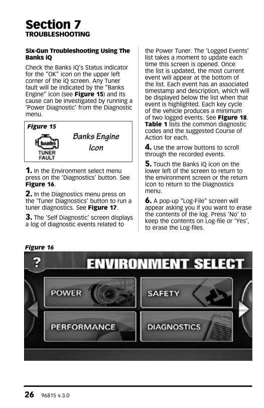
check the Banks iQ’s Status indicator for the “OK” icon on the upper left corner of the iQ screen. Any Tuner fault will be indicated by the “Banks Engine” icon (see Figure 15) and its cause can be investigated by running a ‘Power Diagnostic’ from the Diagnostic menu.
1. In the Environment select menu press on the ‘Diagnostics’ button. See Figure 16.
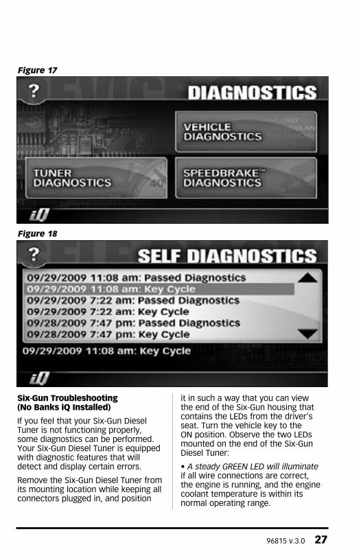
2. In the Diagnostics menu press on the ‘Tuner Diagnostics’ button to run a tuner diagnostics. See Figure 17.
3. The ‘Self Diagnostic’ screen displays a log of diagnostic events related to
the Power Tuner. The ‘Logged Events’ list takes a moment to update each time this screen is opened. Once the list is updated, the most current event will appear at the bottom of the list. Each event has an associated timestamp and description, which will be displayed below the list when that event is highlighted. Each key cycle of the vehicle produces a minimum of two logged events. See Figure 18. Table 1 lists the common diagnostic codes and the suggested course of Action for each.
4. Use the arrow buttons to scroll through the recorded events.
5. Touch the Banks iQ icon on the lower left of the screen to return to the environment screen or the return icon to return to the Diagnostics menu.
6. A pop-up “Log-File” screen will appear asking you if you want to erase the contents of the log. Press ‘No’ to keep the contents on Log-file or ‘Yes’, to erase the Log-files.
Section 7TROUBLESHOOTING
Figure 16
Figure 15
Banks Engine Icon
96815 v.3.0 27
Six-Gun Troubleshooting (No Banks iQ Installed)
If you feel that your Six-Gun Diesel Tuner is not functioning properly, some diagnostics can be performed. Your Six-Gun Diesel Tuner is equipped with diagnostic features that will detect and display certain errors.
Remove the Six-Gun Diesel Tuner from its mounting location while keeping all connectors plugged in, and position
it in such a way that you can view the end of the Six-Gun housing that contains the LEDs from the driver’s seat. Turn the vehicle key to the ON position. Observe the two LEDs mounted on the end of the Six-Gun Diesel Tuner:
• A steady GReeN LeD will illuminate if all wire connections are correct, the engine is running, and the engine coolant temperature is within its normal operating range.
Figure 18
Figure 17
28 96815 v.3.0
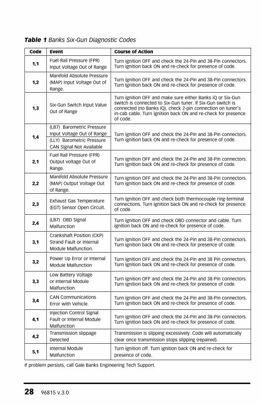
table 1 Banks Six-Gun Diagnostic Codes
Code Event Course of Action
1,1Fuel Rail Pressure (FPR) Input Voltage Out of Range
Turn ignition OFF and check the 24-Pin and 38-Pin connectors. Turn ignition back ON and re-check for presence of code.
1,2Manifold Absolute Pressure (MAP) Input Voltage Out of Range.
Turn ignition OFF and check the 24-Pin and 38-Pin connectors.Turn Ignition back ON and re-check for presence of code.
1,3Six-Gun Switch Input Value Out of Range
Turn ignition OFF and make sure either Banks iQ or Six-Gun switch is connected to Six-Gun tuner. If Six-Gun switch is connected (no Banks iQ), check 2-pin connection on tuner’s in-cab cable. Turn ignition back ON and re-check for presence of code.
1,4
(LB7) Barometric Pressure Input Voltage Out of Range Turn ignition OFF and check the 24-Pin and 38-Pin connectors.
Turn ignition back ON and re-check for presence of code.(LLY) Barometric Pressure cAN Signal Not Available
2,1Fuel Rail Pressure (FPR) Output voltage Out of Range.
Turn ignition OFF and check the 24-Pin and 38-Pin connectors. Turn ignition back ON and re-check for presence of code.
2,2Manifold Absolute Pressure (MAP) Output Voltage Out of Range.
Turn ignition OFF and check the 24-Pin and 38-Pin connectors.Turn ignition back ON and re-check for presence of code.
2,3Exhaust Gas Temperature (EGT) Sensor Open circuit.
Turn ignition OFF and check both thermocouple ring-terminal connections. Turn ignition back ON and re-check for presence of code.
2,4(LB7) OBD Signal Malfunction
Turn ignition OFF and check OBD connector and cable. Turn ignition back ON and re-check for presence of code.
3,1crankshaft Position (cKP) Strand Fault or Internal Module Malfunction.
Turn ignition OFF and check the 24-Pin and 38-Pin connectors.Turn ignition back ON and re-check for presence of code.
3,2Power Up Error or Internal Module Malfunction
Turn ignition OFF and check the 24-Pin and 38 Pin connectors. Turn ignition back ON and re-check for presence of code.
3,3Low Battery Voltage or Internal Module Malfunction.
Turn ignition OFF and check the 24-Pin and 38-Pin connectors. Turn ignition back ON and re-check for presence of code.
3,4cAN communications Error with Vehicle.
Turn ignition OFF and check the 24-Pin and 38-Pin connectors.Turn ignition back ON and re-check for presence of code.
4,1Injection control Signal Fault or Internal Module Malfunction
Turn ignition OFF and check the 24-Pin and 38-Pin connectors.Turn ignition back ON and re-check for presence of code.
4,2Transmission slippage Detected
Transmission is slipping excessively. Code will automatically clear once transmission stops slipping (repaired).
5,1Internal Module Malfunction
Turn ignition off. Turn ignition back ON and re-check for presence of code.
If problem persists, call Gale Banks Engineering Tech Support.
96815 v.3.0 29
If the Six-Gun Diesel Tuner has been moved to a different vehicle, or you are instructed to do so by Banks Technical Staff, it is possible to reset all of the parameters that the Six-Gun has ‘learned’ - presence of an EGT thermocouple or Speed-Loader, etc.
CAUTION: The following procedures can only be carried out with the engine OFF!
1. Turn the vehicle key to ON but DO NOT start the engine.
2. Fully depress the throttle pedal and then release it completely. Repeat 5 times. The GREEN LED will flash when this is completed successfully.
3. Turn the key OFF. Wait 30 seconds, or until the GREEN LED goes off and stays off. Turn the key back to the ON position but DO NOT start the engine.
4. Fully depress the throttle pedal and then release it completely. Repeat 5 times.
-END, SEcTION 8-
Section 8CLEARING LEARNED INFORMATION
• the GReeN LeD will flash if all wire connections are correct, the engine is running, but the engine coolant temperature is not within its normal operating range. The GREEN LED will stop flashing once the engine coolant temperature is within its normal operating range (not to be confused with Speed-Loader flash on power-up).
• No LeDs will illuminate if the fuse on the Six-Gun wiring harness is blown or the wiring harness is not properly connected. If the fuse and all connections are okay, contact Banks Technical Service.
• the ReD LeD will flash in a certain sequence if a connection is incorrect of if there is a problem with the system – this sequence will identify one or more diagnostic codes. A Six-Gun Diesel Tuner’s diagnostic code is comprised of 2 digits. Each code is expressed in a sequence of 2 sets of the flashing red LED separated by a brief flashing of the green LED in between. Each set of a number of red LED flashes represents a digit. A longer flashing of the green LED separates the sequences. The LEDs will continue
to flash to display all the errors, and then repeat. Table 1 lists the common diagnostic codes. For example, if a faulty thermocouple is detected (code “2,3”) by the Six-Gun Diesel Tuner, the following red and green LED flashing sequence is observed when the key is on:
(1) Two times flashing RED LED
(2) One time quick flashing GREEN LED
(3) Three times flashing RED LED
(4) One time longer flashing GREEN LED
The above flashing sequence will repeat continuously. When the problem is corrected, the diagnostic code will be eliminated and replaced by a steady green light. If problem persists, contact Banks Technical Service.
Note: If multiple codes are set, they will be displayed in a series separated by the longer flashing green LeD. When reading codes, make sure to watch the entire series until you see the first code repeat.
-END, SEcTION 7-
30 96815 v.3.0
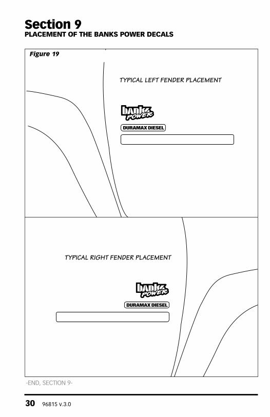
Section 9PLACEMENT OF THE BANKS POWER DECALS
TYPICAL LEFT FENDER PLACEMENT
TYPICAL RIGHT FENDER PLACEMENT
Figure 19
-END, SEcTION 9-
96815 v.3.0 31
If the Six-Gun Diesel Tuner should ever need to be removed from the vehicle, perform the following:
1. Disconnect the Six-Gun’s 38-pin connector from the factory harness.
2. Re-connect the vehicle’s 38-pin connector back into the factory harness.
3. Disconnect the Six-Gun’s 24-pin connector from the factory harness.
4. Re-connect the vehicle’s 24-pin connector back into the factory harness.
5. Disconnect the 2-ring terminals from the EGT thermocouple.
6. Disconnect the 3 small connectors on the ‘In-cab cable’ and gently pull the cable back through the firewall.
7. Remove the Six-Gun Diesel Tuner. Failure to follow the above instructions when removing the module will result in a “check Engine” light on the dash and a Diagnostic Trouble code being stored in the factory computer, in addition to the engine not running.
-END, SEcTION 10-
Section 10REMOVAL OF THE SIx-GUN DIESEL TUNER
�
Figure 20

Gale Banks Engineering 546 Duggan Avenue • Azusa, cA 91702 (626) 969-9600 • Fax (626) 334-1743
Product Information & Sales: (888) 635-4565customer Support: (888) 839-5600 Installation Support: (888) 839-2700
bankspower.com