Embed Size (px)
Citation preview
Islamic University of Gaza
Deanery of Higher Studies
Faculty of Engineering
Computer Engineering Department
Banking and Payment System via Mobile Devices with Biometrics Authentication
Kanaan A. El Bhissy
A Thesis Submitted in Partial Fulfillment of the Requirements for the Degree of Master of Science in Computer Engineering.
Supervisor
Prof. Hatem M. Hamad (professor of computer engineering)
Palestine, Gaza
2011
II
D edicationD edicationD edicationD edication
� To my beloved mother Su’ad
� To my beloved wife Yasmeen
� To my brother Monther
� To my sisters
III
A cknow ledgem entsA cknow ledgem entsA cknow ledgem entsA cknow ledgem ents
Praise is to Allah, the Almighty for having guided me at every stage of my life.
This thesis is the result of years of work whereby I have been accompanied and supported by many people. It is wonderful that I now have the opportunity to express my gratitude to all of them.
This work would not have been possible without the constant encouragement and support I received from prof. Hatem hamad, my advisor and mentor. I would like to express my deep and sincere gratitude to him. His understanding and personal guidance have provided a good basis for the present thesis.
I also extend my thanks to prof. Mohammad Mikki and Dr. Aiman Abu Samra the members of the thesis discussion committee.
Also, I would like to take this opportunity to express my profound gratitude to my beloved family – my mother, and my wife- without whom I would ever have been able to achieve so much
Last, but certainly not least, I want to thank my friends and Colleagues, for their moral support during this study.
IV
ABSTRACT The increase in the number of subscribers companies cellular phones in Palestine, and thus steadily for mobile phones, and those modern ones, opens the way for a required new field of mobile applications, those concerned with trade and business, including banking systems, as well as develop new ways to accomplish the sale and purchase .
Have been better as researchers in the field of computer to be proactive in going into this area, so we in this thesis developed a model for one of these innovative systems, a model be preceded by a study meets the systems mobile phones for payment, and banking services in the world, then get out perception of the entire new system is well suited with the reality of banks in Palestine, and allows the user to buy a commodity or service, or to sell it through his mobile phone at any time, or at any place without any extra cost or pricing.
The model which we have designed is going through stages of the life cycle of one of the latest and the most important methods for object-oriented software engineering, to design concurrent, distributed, and real-time applications with the Unified Modeling Language (UML), a stage of the system requirements specification, and the stage of system analysis, which describes the relations between the objects that reflects the problem domain, and the stage of system design that accurately describe the system structure and structure of active objects and their interrelationships, and this stage focuses on the solution domain.
Protection of digital data is of concern to many people since the occurrence of electronic archiving system, with the occurrence of mobile phone software has become an urgent need to protect and secure the mobile phone itself, or one of its applications from the exploration or the futility of non-authorized use. With the great progress of the capacity, and the capabilities of the mobile phone which has become a small computer, it becomes possible to secure mobile with biometric technologies, as the goal of this thesis is to get out a full system for less cost to the user, we have chosen the voice print as a biometric that you only need a traditional microphone to pick up sound such as that found in all mobile phones.
We have designed and programmed the speaker-verification system, which does not depend on the text, i.e. that the system can verify the speaker regardless of the phrase pronounced. System works entirely on a mobile phone to pick up the sound, and analyze it to extract the characteristics of the vocal tract, then the verification process, which compares the extracted speech’s features with the stored vocal model audio of the speaker, which can be modified when necessary.

V
������� �� � �����
������� ��� ����� .� ����
ان ازدياد عدد مشتركي شركات الهواتف الخلوية في فلسطين، وبالتالي انتشار مضطرد ألجهزة الهواتف النقالة، وتلك
من تطبيقات الهواتف النقالة، تلك التي تختص بالتجارة واالعمال الحديثة منها، يفتح الطريق امام مجال جديد ومطلوب
والتي تشمل االنظمة البنكية، كذلك استحداث طرق جديدة إلنجاز عمليات البيع والشراء.
فكان حري بنا كباحثين في مجال الحاسوب ان نكون سباقين في الخوض في هذا المجال، فقمنا في هذه االطروحة
هذه االنظمة المبتكرة، انموذج يكون مسبوقا بدراسة مستوفية ألنظمة الهواتف النقالة للدفع، بوضع أنموذج إلحدى
وخدمات البنوك في العالم، ثم الخروج بتصور كامل لنظام جديد مناسب تماما لواقع البنوك في فلسطين، ويتيح للمستخدم
ي وقت، او في أي مكان بدون أي تسعيرة او تكلفة ان يشتري سلعة او خدمة، او ان يبيعها عن طريق هاتفه النقال في أ
اضافية.
االنموذج الذي قمنا بتصميمه يمر بمراحل دورة حياة احدى احدث واهم الطرق لهندسة البرمجيات الشيئية، لتصميم
النظام مع لغة النمذجة الموحدة، مرحلة توصيف متطلبات النظام، ومرحلة تحليل واآلنية االنظمة المتزامنة والموزعة
الذي يصف العالقات بين الكائنات البرمجية التي تعكس مجال المشكلة نفسها، ومرحلة تصميم النظام التي تصف بدقة
بنية وهيكلة الكائنات العاملة وترابطها، وتركز هذه المرحلة على المجال الحل.
االلكترونية، ومع ظهور برامج الهاتف حماية البيانات الرقمية امر يشغل بال كثير من الناس منذ ظهور نظام االرشفة
النقال اصبحت الحاجة ملحة لحماية و تامين الهاتف النقال نفسه او احد تطبيقاته من تلصص او عبث الغير مخولين
باستخدامه. مع التقدم الكبير لقدرات الهاتف النقال الذي اصبح بمثابة حاسوب صغير متنقل اصبح باإلمكان تأمينه
ت الحيوية، وحيث ان هدف هذه االطروحة هو الخروج بنظام كامل باقل التكاليف المترتبة على المستخدم، بتقنيات السما
اخترنا بصمة الصوت كسمة حيوية التي تحتاج فقط الى القط صوت تقليدي كالذي يوجد في جميع الهواتف النقالة.
، أي ان النظام يمكنه التحقق من المتكلم بغض قمنا بتصميم وبرمجة نظام التحقق من المتكلم، ال يعتمد على النص
النظر عن العبارة التي نطقها. النظام يعمل كليا على الهاتف النقال من التقاط الصوت، وتحليله الستخراج الخصائص
للمتكلم المميزة لنبرة الصوت، ثم عملية التحقق وذلك بمقارنة خصائص الصوت المستخرجة مع النموذج الصوتي
الذي يمكن تعديله عند الضرورة.المخزن و
VI
Table Of Contents Dedication………………………………………………………………………………...…II Acknowledgments………………………………………………………………………….ІІІ Abstract………………………………………………………………………………….…IV Abstract (AR)……………………………………………………………………………….V Table of contents…………………………………………………………………………...VI List of tables………………………………………………………………………………...X List of figures………………………………………………………………………………XI
1 Introduction 1 1.1 Problem definition…………………………………………………………..….1 1.2 Mobile commerce…………………………………………………………………..2 1.3 Technologies for mobile payments………………………………………..………..2
1.3.1 Short message service (SMS)………………………………………………..2 1.3.2 Unstructured supplementary service delivery.………………………………3 1.3.3 WAP/GPRS………………………………………………………………….3 1.3.4 Phone-based application (J2ME/BREW)……………………………………3 1.3.5 SIM-based application……………………………………………………….3 1.3.6 Near field communication (NFC) …………………………………………...3 1.3.7 Dual chip…………………………………………………………………….4 1.3.8 Mobile wallet………………………………………………………………..4
1.4 Biometric authentication………….………………………………………………..4 1.5 COMET…………………………………………………………………………….5 1.6 Motivation…………………………………………………………………………..6 1.7 Thesis outline……………………………………………………………………….6
2 Related literature reviews 8
2.1 Overview……………………………………………………………………………8 2.2 Mobile banking applications………………………………………………………..8 2.3 Mobile payment applications……………………………………………………….9
2.3.1 Mobile proximity payments………………………………………………..10 2.3.2 Mobile remote payments…………………………………………………...11
2.4 Mobile biometric recognition applications………………………………………..11 2.1.1 Mobbeel (mobbeel.com)………………………………................................12
3 Proposed system: strategies, algorithms, and specification 13
3.1 Overall description………………………………………………………………..13 3.2 Debit mobile specification………………………………………………………..16 3.3 Soft Cheque……………………………………………………………………….18 3.4 Security..…………………………………………………………………………..19 3.5 Speaker verification system……………………………………………………….22 3.6 System requirements specification (SRS)…………………………………………26
4 System analysis model 30
VII
4.1 Static model……………………………………………………………………….30 4.1.1 Static modeling of the problem domain……………………….…………..30 4.1.2 Static modeling of the system context…………………………………….31 4.1.3 Static modeling of the entity classes………………………………………32
4.2 Object structuring…………………………………………………………………33 4.2.1 Major subsystem…………………………………………………………...33 4.2.2 Mobile subsystems object structuring: interface objects………………..…35 4.2.3 Mobile client subsystem object structuring………………………………..36 4.2.4 payment subsystem object structuring……………………………………..37 4.2.5 Banking server subsystem object structuring………………………………38
4.3 Dynamic model……………………………………………………………………38 4.3.1 Message sequence description for create voice print use case………….…38 4.3.2 Message sequence description for Login use case…………………….…..39 4.3.3 Message sequence description for Mobile client: Validate PIN use
case……………………………………………………………………..…..40 4.3.4 Message sequence description for Server side: Validate PIN use
case…………………………………………………………………………41 4.3.5 Message sequence description for mobile client: Charge mobile use
case……………………………………………………………………..…..42 4.3.6 Message sequence description for Server side: Charge mobile use
case…………………………………………………………………………43 4.3.7 Message sequence description for mobile client: Discharge mobile use
case…………………………………………………………………….…..44 4.3.8 Message sequence description for server side: Discharge mobile use
case………………………………………………………………..……….45 4.3.9 Message sequence description for mobile client: Query account use
case…………………………………………………………………………46 4.3.10 Message sequence description for Server side: Query account use
case…………………………………………………………..……………..47 4.3.11 Message sequence description for Mobile client: Synchronize balance use
case…………………………………………………………………..……..48 4.3.12 Message sequence description for Server side: Synchronize balance use
case……………………………………………………..…………………..49 4.3.13 Message sequence description for Payment: Send Cheque use
case……………………………………………………………………..…..50 4.3.14 Message sequence description for Payment: Receive Cheque use
case…………………………………………………………………………52 4.3.15 Message sequence description for Payment: Check balance use
case…………………………………………………………………..……..53 4.3.16 Message sequence description for Payment customer: Cash Cheque use
case………………………………………………………………..………..53
VIII
4.3.17 Message sequence description for Payment server side: Cash Cheque use case…………………………………………………………………………54
4.4 Mobile banking and payment system statechart……………………………..……55 4.4.1 Authentication statechart…………………………………………….……..55 4.4.2 Mobile client statechart…………………………………………………….60 4.4.3 Payment statechart………………………………………………………….65
5 System design model 74
5.1 System consolidating collaboration model……………………………………….74 5.1.1 Authentication subsystem consolidating collaboration model……..74 5.1.2 Mobile Client subsystem consolidating collaboration model……...75 5.1.3 Payment subsystem consolidating collaboration model…………...76 5.1.4 Mobile Banking Service consolidating collaboration model………77
5.2 Task structuring……………………….………………………………………….78 5.2.1 Authentication subsystem task structuring architecture……………78 5.2.2 Mobile Client subsystem task structuring architecture…………….80 5.2.3 Payment subsystem task structuring architecture………………….82 5.2.4 Mobile Banking Service subsystem task structuring architecture…84
5.3 Class design ……………………….……………………………………………..85 5.3.1 Authentication subsystem classes design…………………………..85 5.3.2 Mobile Client subsystem classes design…………………………...87 5.3.3 Payment subsystem classes design………………………………....89 5.3.4 Mobile Banking Service subsystem classes design…………….….91
5.4 Detailed design ……………………….…………………………………………..92 5.4.1 DSPController composite task……………………………………..92 5.4.2 VQ&EUDistance composite task…………………….…………….93 5.4.3 Mobile Control composite task……………………………….……94 5.4.4 Payment Control composite task………………………………...…95
6 Speaker verification system: implementation, and experimental results 97
6.1 Recording speech……………………………………………………………..…..97 6.2 ARM VFP architecture…………………………………………………………...98 6.3 Natural logarithm……………………………………………………..…………100 6.4 Data privacy…………………………………………………………….……….103 6.5 Natural logarithm methods experiments and results…………………………….104 6.6 Calculating the threshold……………………………………………….……….107
7 Conclusion and future work 109
7.1 Conclusion………………………………………………..………….……….....109 7.2 Future work…………………………………………………….……….……….110
IX
References 111 Appendix A: system requirement specification 117
X
List Of Tables
3.1: Insert voice print use case description…………………………………………….…..27 3.2: Login use case description…………………………………………………………….28 5.1: Message Dictionary for consolidated Authentication Subsystem……………………..75 5.2: Message Dictionary for consolidated Mobile Client Subsystem……………………...75 5.3: Message Dictionary for consolidated Payment Subsystem…………………………...76 6.1: Converting 100.25 decimal to floating-point form…………………….......................99 6.2: Converting a floating-point from to equivalent decimal number…….......................100 6.3: Speaker verification accuracy depending on Codebook Entries……………………..108 A.1: Check balance use case description………………………………………………....117 A.2: Validate PIN use case description…………………………………………………...118 A.3: Query account use case description………………………………….......................119 A.4: Cash Cheque use case description…………………………………………………...120 A.5: Charge Mobile use case description…………………………………………………122 A.6: Discharge mobile use case description……………………………………………...124 A.7: Synchronize Balance use case description………………………………………..…125 A.8: Do payment use case description…………………………………...……………….126 A.9: Send Cheque use case description……………………………………....................127 A.10: Generate Cheque use case description…………………………………………..…129 A.11: Receive Cheque use case description………………………………......................130
XI
List Of Figures
1.1: COMET object-oriented software life cycle mode……………………………………..6 2.1: Translink system distribution………………………………………………………….10 2.2: Biometric technologies classification.………………………………………………...11 3.1: Overall Organization’s Servers………………………………………………………..14 3.2: A Bank System environment.…………………………………………………………15 3.3: A Bank’s Servers.…………………………………………………………………..…15 3.4: Transfer soft Cheque scenario…………………………………………………………21 3.5: MFCC processor block diagram……………………………………………………...23 3.6: LBG algorithm flow chart diagram……………………………………………………24 3.7: Banking and payment application use case diagram…….…………………………....27 4.1: Conceptual static model for the problem domain: physical classes…………………...30 4.2: Mobile Banking System context class diagram……………………………………….31 4.3: Conceptual static model for the problem domain: entity classes……………………...31 4.4: Conceptual static model for the Mobile Banking system: class attributes……………33 4.5: mobile banking system: major subsystems…………………………………………...34 4.6: subsystem packaging of use cases…………………………………………………….35 4.7: Mobile subsystems external classes and interface classes…………………………….36 4.8: Mobile client subsystem classes………………………………………………...…….37 4.9: Payment subsystem classes……………………………………………………………37 4.10: Authentication subsystem classes……………………………………………………38 4.11: collaboration diagram: Create voice print use case………………………………….39 4.12: Collaboration diagram: Login use case……………………………………………....40 4.13: Collaboration diagram: Mobile client Validate PIN use case…………………..……41 4.14: Collaboration diagram: Server Side Validate PIN use case……………………..…...42 4.15: Collaboration diagram: Mobile client Charge mobile use case……………………...43 4.16: Collaboration diagram: Server Side Charge mobile use case………………………..44 4.17: Collaboration diagram: Mobile client Discharge mobile use case…………………..45 4.18: Collaboration diagram: Server side Discharge mobile use case……………………..46 4.19: Collaboration diagram: Mobile client Query account use case…………………...…47 4.20: Collaboration diagram: Server side Query account use case………………………...48 4.21: Collaboration diagram: Mobile client Synchronize balance use case……………….49 4.22: Collaboration diagram: Server side Synchronize balance use case………………….50 4.23: Collaboration diagram: Payment Send Cheque use case…………………………….51 4.24: Collaboration diagram: Payment Receive Cheque use case…………………………52 4.25: Collaboration diagram: Payment check balance use case……………………………53 4.26: Collaboration diagram: Payment customer Cash Cheque use case………………….54 4.27: Collaboration diagram: Payment server side Cash Cheque use case………………...55 4.28: Top-level statechart for DSP Control………………………………………………...56 4.29: Statechart for DSP control: Test environment & Extract features composite states...58 4.30: Statechart for DSP control: verify speaker composite state………………………….59 4.31: Statechart for DSP control: create voice print composite state………………………60
XII
4.32: Top level statechart for mobile client control………………………………………..61 4.33: Statechart for mobile client control: Processing Customer Input composite state…..63 4.34: Statechart for mobile client control: Processing Transaction composite state………64 4.35: Statechart for mobile client control: Terminating Transaction composite state……..65 4.36: Top level statechart for Payment control…………………………………………….66 4.37: Statechart for Payment control: Sending Soft Cheque composite state……………...68 4.38: Statechart for Payment control: Receiving Soft Cheque composite state……………70 4.39: Statechart for Payment control: Cash soft Cheque composite state………………….72 4.40: Statechart for Payment control: Termination Transaction composite state………….73 5.1: Consolidated collaboration diagram for Authentication subsystem…………………..74 5.2: Consolidated collaboration diagram for Mobile Client subsystem……………………75 5.3: Consolidated collaboration diagram for Payment subsystem…………………………76 5.4: Consolidated collaboration diagram for Mobile Banking Service subsystem………..78 5.5: Task architecture: initial concurrent collaboration diagram for Authentication subsystem……………………………………………………………………………...79 5.6: Task architecture diagram for Authentication subsystem: task interface……………..80 5.7: Task architecture: initial concurrent collaboration diagram for Mobile Client subsystem. …………………………………………………………………………….81 5.8: Task architecture diagram for Mobile Client subsystem: task interface……………...82 5.9: Task architecture: initial concurrent collaboration diagram for Payment subsystem…82 5.10: Task architecture diagram for Payment subsystem: task interface…………………..83 5.11: Task architecture: initial concurrent collaboration diagram for Mobile Banking Service subsystem……………………………………………………………………84 5.12: Task architecture diagram for Mobile Banking Service subsystem: task interface…85 5.13: Authentication subsystem information hiding classes……………………………….86 5.14: Mobile Client GUI classes………………………………………………………...…87 5.15 Mobile Client subsystem information hiding classes…………………………………88 5.16: Payment customer GUI classes………………………………………………………89 5.17: Payment subsystem information hiding classes……………………………………...90 5.18: Mobile Banking Service subsystem information hiding classes…………………91-92 5.19: DSPController task……………………………………………………………..……93 5.20: VQ&EUDistance task………………………………………………………….…….94 5.21: Mobile Control task………………………………………………………………….95 5.22: Payment Control task………………………………………………………………...96 6.1: Average error rate in small numbers (range 1)………………………………………105 6.2: Average speed up for small numbers (range 1)……………………………………...105 6.3: Average error rate for large numbers (range 2)……………………………………...106 6.4: Average speed up for large numbers (range 2)………………………………………106 6.5: Threshold and error rate plot from NTIMIT8………………………………………..108
1
Chapter 1
INTRODUCTION
1.1 problem definition
Banks in Palestine are suffering from technical; manage mental, economical and communicational problems. The technical side means lack of services for clients who are interested in remotely querying, these queries may be simple and easy and needn’t many efforts but client must go to bank to get such information and services. Suppose that client is in the middle of any deal and cannot leave customers then must go to the bank to get the needed information ( e.g. his account balance and credit transferring), in this case he may lose the deal.
Another client goes to the bank for a one minute procedure, many times in this case he
waits in long queue, especially in the salary cashing period here he will spend 2 -4 hours. Employees (bank customers) may suffer a lot in non-efficient cashing (lack of money) as result of this serious problem they can't buy what the need of different goods so this will effect on the selling-buying movement in the whole area then will cause a country economical parallels. As a result of these problems the social situation in the country will be badly affected, that is to say because of the delayed salaries people will live in financial distress. This leads to trust issue; clients may stop trusting their banks and their policies because it seems that the bank systems and policies are not made to help and relief customers but they increase their suffering and effect the country economy and industry. No doubt that this serious social and economic problems cause unemployment and crime in the Palestinian society.
On the other hand many people think that Visa Card may solve most of these problems, even if it can solve some of them but it also brings a lot of more complicated financial problems. It's important to mention that the VC have been spread among a limited category in the Palestinian society, even big merchants don't deal with VC.
2
No doubt that what we are hearing or watching on T.V about manipulations and tricks including VC and it’s high taxes.
The traditional checks system (paper) is useless and also containing a lot of disadvantages like reversed checks and fake ones or these without balance, absolutely this system is not successful with lost checks or stolen ones because if they are signed directly cashed, also paper checks easy to be damaged.
Personal Identification Number (PIN) code which is a four digits can be forgotten or easily stolen, many customers keep PIN data with its debit card (as written on paper and inserted in the cover of card) , so when this card is stolen or lost the PIN goes with it.
1.2 Mobile Commerce
Mobile Commerce, also known as M-Commerce or mCommerce, is the ability to conduct commerce using a mobile device. such as a mobile phone (cell phone), a PDA, a smartphone, or other emerging mobile equipment such as dashtop mobile devices. Mobile Commerce has been defined as follows: "Mobile Commerce is any transaction, involving the transfer of ownership or rights to use goods and services, which is initiated and/or completed by using mobile access to computer-mediated networks with the help of an electronic device. [1].
Mobile banking (also known as M-Banking, mbanking, SMS Banking etc.) is a term used for performing balance checks, account transactions, payments etc. via a mobile device such as a mobile phone or Personal Digital Assistant (PDA). Mobile banking today (2007) is most often performed via SMS or the Mobile Internet but can also use special programs, called clients, downloaded to the mobile device.
Mobile business is any activity conducted over a wireless telecommunications network or from mobile devices. This includes business to customer (B2C) and business to business (B2B) commercial transactions as well as the transfer of information and services via wireless mobile devices. [2].
1.3 Technologies for Mobile Payments
The mobile technology landscape provides various possibilities for implementing m-payments. Essentially, a GSM mobile phone may send or receive information (mobile data service) through three possible channels – SMS, USSD or WAP/GPRS. The choice of the channel influences the way m-payment schemes are implemented. Secondly, the m-payment client application may reside on the phone or else it may reside in the subscriber identity module (SIM). We briefly describe NFC technology as another possibility.
1.3.1 Short Message Service (SMS)
3
This is a text message service that enables short messages (140-160 characters) that can be transmitted from a mobile phone. Short messages are stored and forwarded by SMS centers. SMS messages have a channel of access to phone different from the voice channel [6]. SMS can be used to provide information about the status of one’s account with the bank (informational) or can be used to transmit payment instructions from the phone (transactional).
1.3.2 Unstructured Supplementary Services Delivery (USSD) Unstructured Supplementary Service Data (USSD) is a technology unique to GSM. It is a capability built into the GSM standard for support of transmitting information over the signaling channels of the GSM network. USSD provides session-based communication, enabling a variety of applications. USSD is session oriented transaction-oriented technology while SMS is a store-and-forward technology. Turnaround response times for interactive applications are shorter for USSD than SMS [70].
1.3.3 WAP/GPRS
General Packet Radio Service (GPRS) is a mobile data service available to GSM users. GPRS provides packet-switched data for GSM networks. GPRS enables services such as Wireless Application Protocol (WAP) access, Multimedia Messaging Service (MMS), and for Internet communication services such as email and World Wide Web access in mobile phones.
1.3.4 Phone-based Applica�on (J2ME/BREW) The client m-payment application can reside on the mobile phone of the customer. This
applica�on can be developed in Java (J2ME) for GSM mobile phones and in Binary Runtime
Environment for Wireless (BREW) for CDMA mobile phones. Personalization of the phones can
be done over the air (OTA).
1.3.5 SIM-based application
The subscriber identity module (SIM) used in GSM mobile phones is a smart card i.e., it is a small chip with processing power (intelligence) and memory. The information in the SIM can be protected using cryptographic algorithms and keys. This makes SIM applications relatively more secure than client applications that reside on the mobile phone. Also, whenever the customer acquires a new handset only the SIM card needs to be moved [7]. If the application is placed on the phone, a new handset has to be personalized again.
1.3.6 Near Field Communication (NFC)
4
NFC is the fusion of contactless smartcard (RFID) and a mobile phone. The mobile phone can be used as a contactless card. NFC enabled phones can act as RFID tags or readers. This creates opportunity to make innovative applications especially in ticketing and couponing [8]. The ‘Pay-Buy Mobile’ project launched by the GSM Association (fourteen mobile operators are part of the initiative) targets 900 million mobile users with a common global approach using NFC [9]. 1.3.7 Dual Chip Usually the m-payment application is integrated into the SIM card. Normally, SIM cards are purchased in bulk by telecom companies and then customized for use before sale. If the m-payment application service provider has to write an m-payment application in the SIM card, this has to be done in collaboration with the telecommunications operator (the owner of the SIM). To avoid this, dual chip phones have two slots one for a SIM card (telephony) and another for a payment chip card. Financial institutions prefer this approach as they can exercise full control over the chip and the mobile payment process [10]. But, customers would have to invest in dual chip mobile devices.
1.3.8 Mobile Wallet A m-payment application software that resides on the mobile phone with details of the customer (and his or her bank account details or credit card information) which allows the customer to make payments using the mobile phone is called as a mobile wallet. Customers can multi-home with several debit or credit payment instruments in a single wallet. Several implementations of wallets that are company-specific are in use globally. See blazewallet.com.
1.4 Biometric authentication
Biometrics is the science and technology of measuring and analyzing human body characteristics such as fingerprints, retina veinal patterns, irises, voice patterns, facial patterns, and hand/finger measurements for authentication or identification purposes. As the "state-of-the-art biometrics excellence roadmap" sidebar indicates, authentication by biometric verification is becoming increasingly common, and biometric technologies are beginning to appear in many facets of everyday life [3].
Voice recognition or speaker recognition is the computing task of validating a user's claimed identity using characteristics extracted from their voices. There are two major applications of speaker recognition technologies and methodologies. If the speaker claims to be of a certain identity and the voice is used to verify this claim, this is called verification or identification. On the other hand, identification is the task of determining an unknown speaker's identity. In a sense speaker verification is a 1:1 match where one speaker's voice is matched to one template (also called a "voice print" or "voice model") whereas speaker identification is a 1:N match where the voice is compared against N templates.
5
From a security perspective, identification is different from verification. For example, presenting your passport at border control is a verification process - the agent compares your face to the picture in the document. Conversely, a police officer comparing a sketch of an assailant against a database of previously documented criminals to find the closest match(es) is an identification process. Speaker verification is usually employed as a "gatekeeper" in order to provide access to a secure system (e.g.: telephone banking). These systems operate with the user's knowledge and typically require their cooperation. Speaker identification systems can also be implemented without the user's knowledge to identify talkers in a discussion, alert automated systems of speaker changes, check if a user is already enrolled in a system, etc. Speaker recognition systems fall into two categories: text-dependent and text-independent. If the text must be the same for enrollment and verification this is called text-dependent recognition. In a text-dependent system, prompts can either be common across all speakers (e.g.: a common pass phrase) or unique. In addition, the use of shared-secrets (e.g.: passwords and PINs) or knowledge-based information can be employed in order to create a multi-factor authentication scenario. Text-independent systems are most often used for speaker identification as they require very little if any cooperation by the speaker. In this case the text during enrollment and test is different. In fact, the enrollment may happen without the user's knowledge, as in the case for many forensic applications. As text-independent technologies do not compare what was said at enrollment and verification, verification applications tend to also employ speech recognition to determine what the user is saying at the point of authentication [4,5].
1.5 COMET
Concurrent [67] or Collaborative [47] Object Modeling and architectural design mEThod COMET is a design method for concurrent, distributed, and real-time system.
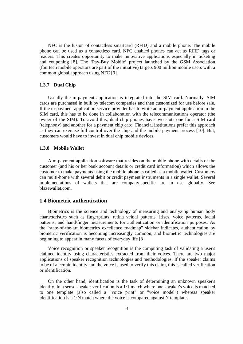
The development process for COMET method is an object-oriented software process, which is compatible with the Unified Software Development Process (USDP) [68] and the spiral model [69]. The COMET object-oriented software life cycle model is a highly iterative software development process based around the use case concept. The figure 1.1 shows this lifecycle as a block diagram.
6
Figure (1.1): COMET object-oriented software life cycle mode
1.6 Motivation
In this thesis, we can conclude our contribution in:
1. We proposed a new approach of mobile commerce, named Debit Mobile.
2. We introduced a new type of electronic Cheque, named soft Cheque.
3. We introduced a new algorithm for soft Cheque offline verification, depending on a new proposed structure of mobile digital certificate.
4. We modeled our banking and payment system using COMET method.
5. We designed, and implemented speaker verification running completely on mobile devices, non-distributed system in J2ME.
6. We implemented three methods of the natural algorithm function in J2ME, all of them are faster than traditional java implementation, and they have high accuracy.
1.7 Thesis outline
The remainder structure of this thesis as follows:
chapter 2 Related literature review: gives an overview of mobile banking, and payment, and explores some biometric authentication technologies for mobile devices.
Chapter 3 Proposed system: Strategies, Algorithms, and Specification: explores and explains in details our proposed system, novel strategies in mobile payment, a new mechanism for speaker verification for mobile devices, existed algorithms for extracting
7
speech features, and finally full specification of our system as system requirements specification (SRS) document in IEEE format [67].
Chapter 4 System analysis model: in this chapter we modeled the complete system, which reflects the problem domain, the system analysis model consists of static and dynamic models, also composite state charts will be developed.
Chapter 5 System design model: the overall system architecture will be investigated, and described briefly, structuring system to subsystem and to concurrent tasks, others system design details will be documented, and all necessary diagrams and descriptions that reflects solution domain.
Chapter 6 Speaker verification system: implementation, and experimental results: for speaker verification subsystem and natural logarithm method in three ways discussion.
Chapter 7 conclusion and future work.
8
Chapter 2
RELATED LITERATURE REVIEWS
2.1 Overview
M-commerce is a natural extension of E-commerce, the wide ubiquity of mobile devices opens new fields of business, creates new types of services, and attracts new types of customers.
Most mobile financial applications are simply mobile versions of their wireline counterparts, but they have the potential to turn a mobile device into a business tool, replacing bank branches, ATMs, and credit cards by letting a user conduct financial transactions with a mobile device, anytime, anywhere. These services fall into two broad categories: mobile banking and mobile payments.
Mobile phone devices are targets for thefts and lost, when using these devices as business tools, many confidential data is stored on them, many business applications are installed on these mobile phones. It is very dangerous to keep all these data and applications without protection. Studies have shown that even though most of the cell phone users are aware of the PIN security feature more than 50% of them are not using it either because of the lack of confidence in it or because of the inconvenience. A large majority of those users believes that an alternative approach to security would be a good idea [11].
2.2 Mobile banking applications
Throughout Europe, The united states, and Asia, an increasing percentage of banks are offering mobile phones access to financial and account information. These banks enable their customers to use their mobile devices to check balances, monitor transactions, obtain other account information, transfer funds, locate branches or ATMs, and, sometimes, pay bills [12].
9
The ICICI bank (icicibank.com) offers many mobile banking services, one of these services is iMobile and iMobile mShop applications. iMobile offers a range of services in a simple consolidated menu. Now you can make banking transactions like funds transfer, bill payment, balance enquiry, locate a branch, view your last 5 transactions and much more.
iMobile is a rich client based application that downloads instantly onto your mobile phone and functions similar to any other mobile application menu. With its newer features, smarter interface, quicker navigation and enhanced functionality, iMobile is as simple as ABC....
Now iMobile powered with mShop not only gives you a convenient banking solution, but also gives the facility to purchase and pay for goods or services using mobile phones.
Features of iMobile:
1. Banking using iMobile: With its proficient user interface you can now make payments, transfer funds, place request and access banking information with just a single click on your Saving Accounts, Loan Accounts, Demat Accounts and Credit Cards.
2. It is Safe and Secure: You will need to enter your unique 4-digit PIN every time you make a payment transaction. This PIN is selected by you at the time of registration.
3. iMobile mShop: With the new mobile shop you can now recharge your prepaid mobile number, book movie tickets with Book My Show, book flight tickets with Make My Trip and much more in just few clicks.
iMobile mShop service is available for customers who activated iMobile after 31st Jan 2010. In case you have activated iMobile before the mentioned date, please upgrade the iMobile application by clicking on the Upgrade option in the Options menu.
4. Continuous Updates: Features and services are continuously updated keeping you ahead of the game always.
5. Higher funds transfer limit : It allows you to transfer funds to any bank account, pay bills and do prepaid mobile recharge up to a new enhanced limit* of Rs. 50,000/- per day.
6. Diversity of handsets: ICICI Bank is the only bank covering more than 650 GSM and CDMA handsets.
2.3 Mobile payment applications
The term mobile payment refers to payment transactions initiated or confirmed using a person’s cell phone or smartphone. These transactions include such things as point-of-sale (POS) purchases, transferring money to a person or business, or purchasing a product or service remotely. Mobile POS payments are also known as proximity or contactless payments. Mobile proximity payments are usually handled using near field communication
10
(NFC) technology. NFC is wireless technology that enables data exchange between devices that are within a distance of 10 centimeters [13].
In contrast, mobile remote payments are those initiated and settled through a combination of the cellular and associated payment networks. Like mobile banking, these person-to-person, person-to-business, or business-to-business payments typically rely on either SMS text messaging or the web to execute the payment.
2.3.1 Mobile Proximity Payments
Bay Area Rapid Transit (BART) offers a mobile service depending on Translink, allows passengers to pay their fares using their mobile phones.
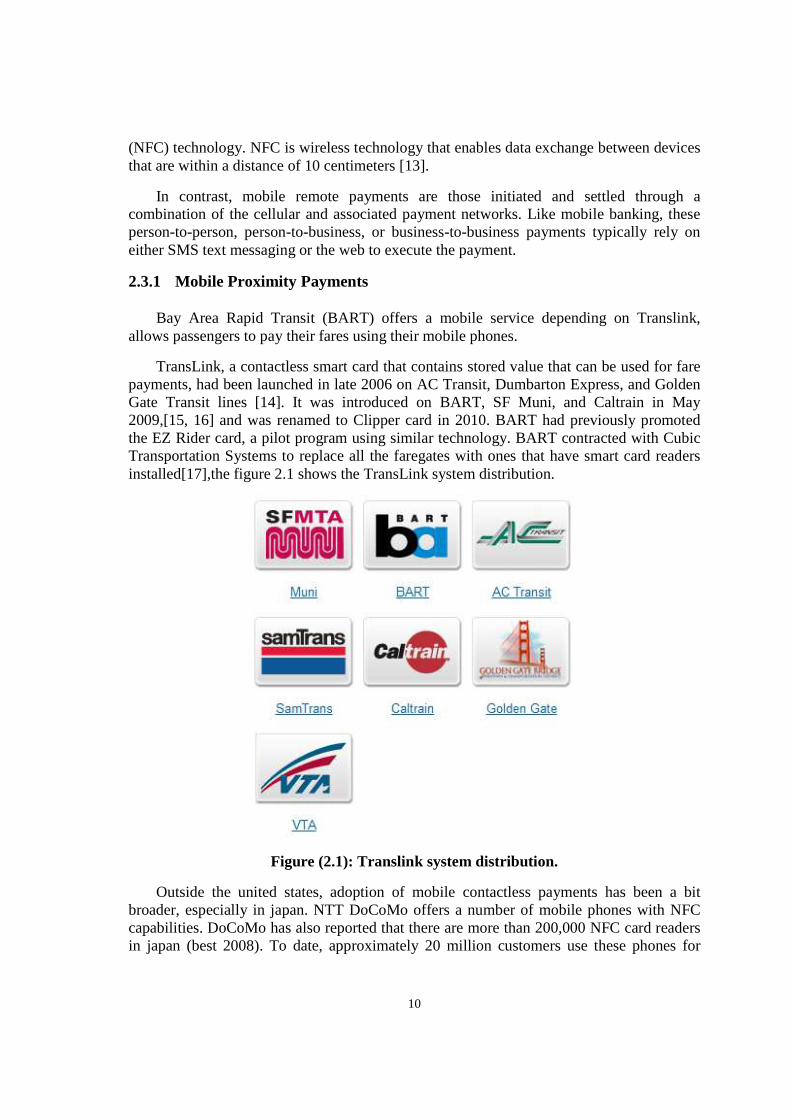
TransLink, a contactless smart card that contains stored value that can be used for fare payments, had been launched in late 2006 on AC Transit, Dumbarton Express, and Golden Gate Transit lines [14]. It was introduced on BART, SF Muni, and Caltrain in May 2009,[15, 16] and was renamed to Clipper card in 2010. BART had previously promoted the EZ Rider card, a pilot program using similar technology. BART contracted with Cubic Transportation Systems to replace all the faregates with ones that have smart card readers installed[17],the figure 2.1 shows the TransLink system distribution.
Figure (2.1): Translink system distribution.
Outside the united states, adoption of mobile contactless payments has been a bit broader, especially in japan. NTT DoCoMo offers a number of mobile phones with NFC capabilities. DoCoMo has also reported that there are more than 200,000 NFC card readers in japan (best 2008). To date, approximately 20 million customers use these phones for
11
debit card transaction. In the future they will also use them as credit cards. Interestingly, taxis in japan are also starting to install NFC readers.
2.3.2 Mobile Remote Payments
A number of initiatives have been launched to support mobile remote payments. These initiatives offers services that enable clients and consumers to use their mobile devices to pay their monthly bills, to shop on the internet, to transfer funds to other individual (P2P payments), and to “top off” their prepaid mobile accounts without having to purchase prepaid phone cards.
In the case of mobile bill payments, Internet shopping, P2P payments, and “topping off”, the processes involved in executing a transaction are basically the same:
1. The payer initiating the payment sets up an account with a mobile payment service provider (MPSP).
2. To make a payment, the payer sends a text message or command to the MPSP that includes the dollar amount and the receiver’s mobile phone number.
3. The MPSP receives the information and sends a message back to payer, confirming the transaction and requesting his or her PIN.
4. The payer receives the request on his mobile device and enters the PIN. 5. When the MPSP receives the payer’s PIN, money is transferred to the third party’s
account (credit or bank account). 6. After the transaction occurs, the payment information is sent to the payer’s device.
2.4 Mobile Biometric Recognition applications
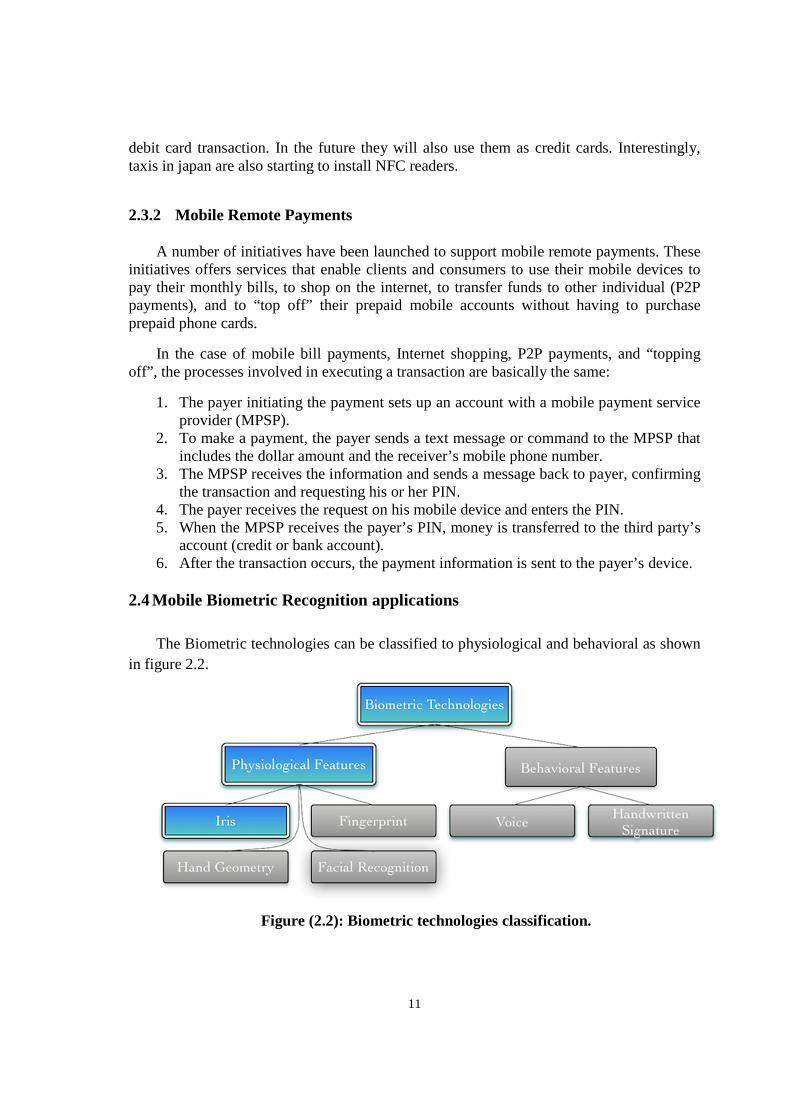
The Biometric technologies can be classified to physiological and behavioral as shown in figure 2.2.
Figure (2.2): Biometric technologies classification.
12
There are many companies offer applications and technologies for biometric authentication. 2.4.1 Mobbeel (mobbeel.com)
Mobbeel provides biometric security solutions (iris, voice and signature recognition...) for mobile devices. The targeted platforms are Android, iPhone, BlackBerry, Symbian, Maemo, Bada and Windows Phone 7. The company offers two technologies: Iris recognition, and Signature recognition:
a) Iris recognition: Mobbeel has concentrated its efforts in the development of this technology, specifically targeting current mobile devices and the wide range of opportunities their features offer. With its technology, iris pattern acquisition does not need a special sensor or infrared light in the mobile device, it simply uses the built-in camera. Most current smart-phones have cameras with enough resolution and sufficient technical specifications to allow for this. The technology has been specially designed to be able to perform the whole recognition process, from the initial capture of the eye, through the acquisition of the biometric iris pattern and final identification of the individual. The technology is capable of processing all the information, taking into account that the samples might be very different. The sophisticated algorithms allow the samples to be taken in a non-controlled environment by the mobile device's built in camera, where the environmental conditions (no special light, different places and distances to the eye, etc) may have had a major impact on the outcome. The technology also works within client/server architecture, where the client (mobile device) is used just as a capture device and the server receives the sample taken by the client, through a secure channel, and performs the recognition process.
b) Signature recognition: Mobbeel has chosen the online recognition model as the fundamental approach in the development of this technology. its implementation of the online model is much more reliable than the offline model, since it is not only based on the final result of the signature but also the behavior patterns of the signature itself (strokes, speed, pressure, time, etc). This significantly raises the level of security and reduces the chances of forgery. It works with the vast majority of touch screens and adapts to individual handset characteristics, being a highly configurable technology. As with iris recognition, the technology works perfectly isolated on a mobile device, performing the capture, processing and identification independently. It is also suited to a client/server architecture where the device just captures the signature and sends it to the server, through a secure channel, for the enrollment or identification process.
13
Chapter 3
PROPOSED SYSTEM: STRATEGIES, ALGORITHMS, AND SPECIFICATION
3.1 overall description
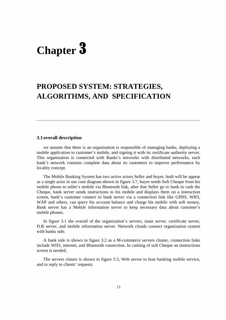
we assume that there is an organization is responsible of managing banks, deploying a mobile application to customer’s mobile, and signing it with its certificate authority server. This organization is connected with Banks’s networks with distributed networks, each bank’s network contains complete data about its customers to improve performance by locality concept.
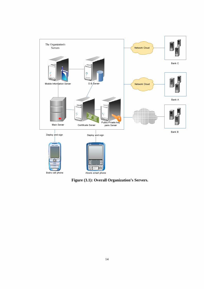
The Mobile Banking System has two active actors Seller and buyer, both will be appear as a single actor in use case diagram shown in figure 3.7, buyer sends Soft Cheque from his mobile phone to seller’s mobile via Bluetooth link, after that Seller go to bank to cash the Cheque, bank server sends instructions to his mobile and displays them on a instruction screen, bank’s customer connect to bank server via a connection link like GPRS, WIFI, WAP and others, can query his account balance and charge his mobile with soft money, Bank server has a Mobile information server to keep necessary data about customer’s mobile phones.
In figure 3.1 the overall of the organization’s servers, main server, certificate server, D.B server, and mobile information server. Network clouds connect organization system with banks side.
A bank side is shown in figure 3.2 as a M-commerce servers cluster, connection links include WIFI, internet, and Bluetooth connection. In cashing of soft Cheque an instructions screen is needed.
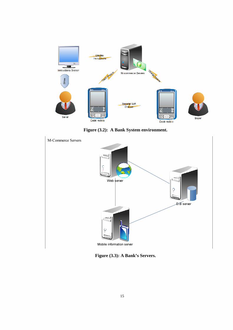
The servers cluster is shown in figure 3.3, Web server to host banking mobile service, and to reply to clients’ requests.
14
Figure (3.1): Overall Organization’s Servers.
Main Server
Mobile Information Server
Certificate Server
Public-Private key
pairs Server
Network Cloud
Bank A
Bank B
The Organization's
Servers
D.B Server
Network Cloud
Bank C
Deploy and sign
Bob's cell phone
Deploy and sign
Alice's smart phone
15
Figure (3.2): A Bank System environment.
Figure (3.3): A Bank’s Servers.
Web server
D.B server
Mobile information server
M-Commerce Servers
16
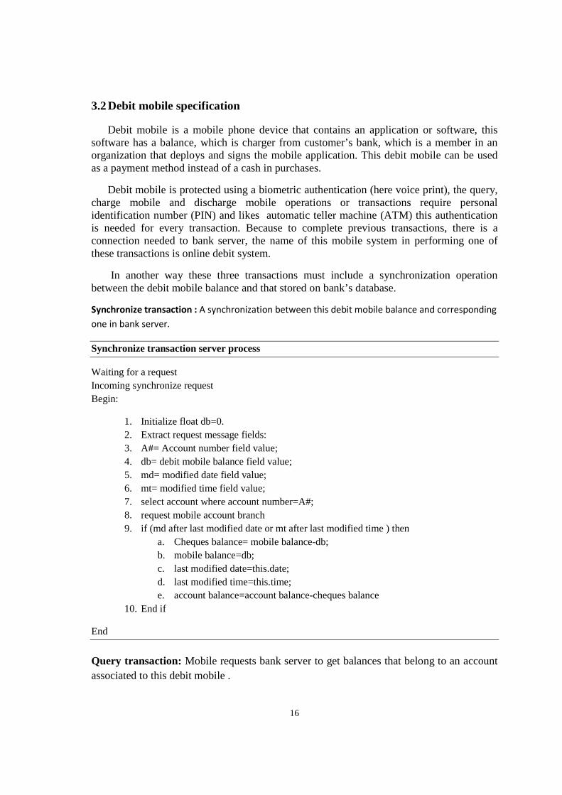
3.2 Debit mobile specification
Debit mobile is a mobile phone device that contains an application or software, this software has a balance, which is charger from customer’s bank, which is a member in an organization that deploys and signs the mobile application. This debit mobile can be used as a payment method instead of a cash in purchases.
Debit mobile is protected using a biometric authentication (here voice print), the query, charge mobile and discharge mobile operations or transactions require personal identification number (PIN) and likes automatic teller machine (ATM) this authentication is needed for every transaction. Because to complete previous transactions, there is a connection needed to bank server, the name of this mobile system in performing one of these transactions is online debit system.
In another way these three transactions must include a synchronization operation between the debit mobile balance and that stored on bank’s database.
Synchronize transaction : A synchronization between this debit mobile balance and corresponding
one in bank server.
Synchronize transaction server process
Waiting for a request Incoming synchronize request Begin:
1. Initialize float db=0. 2. Extract request message fields: 3. A#= Account number field value; 4. db= debit mobile balance field value; 5. md= modified date field value; 6. mt= modified time field value; 7. select account where account number=A#; 8. request mobile account branch 9. if (md after last modified date or mt after last modified time ) then
a. Cheques balance= mobile balance-db; b. mobile balance=db; c. last modified date=this.date; d. last modified time=this.time; e. account balance=account balance-cheques balance
10. End if
End
Query transaction: Mobile requests bank server to get balances that belong to an account associated to this debit mobile .
17
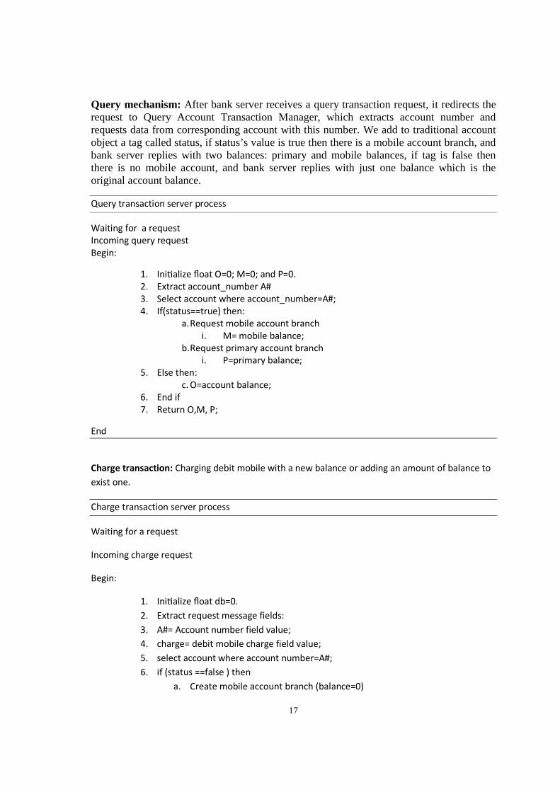
Query mechanism: After bank server receives a query transaction request, it redirects the request to Query Account Transaction Manager, which extracts account number and requests data from corresponding account with this number. We add to traditional account object a tag called status, if status’s value is true then there is a mobile account branch, and bank server replies with two balances: primary and mobile balances, if tag is false then there is no mobile account, and bank server replies with just one balance which is the original account balance.
Query transaction server process
Waiting for a request
Incoming query request
Begin:
1. Ini�alize float O=0; M=0; and P=0.
2. Extract account_number A#
3. Select account where account_number=A#;
4. If(status==true) then:
a. Request mobile account branch
i. M= mobile balance;
b. Request primary account branch
i. P=primary balance;
5. Else then:
c. O=account balance;
6. End if
7. Return O,M, P;
End
Charge transaction: Charging debit mobile with a new balance or adding an amount of balance to
exist one.
Charge transaction server process
Waiting for a request
Incoming charge request
Begin:
1. Ini�alize float db=0.
2. Extract request message fields:
3. A#= Account number field value;
4. charge= debit mobile charge field value;
5. select account where account number=A#;
6. if (status ==false ) then
a. Create mobile account branch (balance=0)
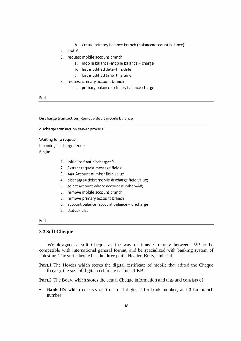
18
b. Create primary balance branch (balance=account balance)
7. End if
8. request mobile account branch
a. mobile balance=mobile balance + charge
b. last modified date=this.date
c. last modified time=this.time
9. request primary account branch
a. primary balance=primary balance-charge
End
Discharge transaction: Remove debit mobile balance.
discharge transaction server process
Waiting for a request
Incoming discharge request
Begin:
1. Initialize float discharge=0
2. Extract request message fields:
3. A#= Account number field value
4. discharge= debit mobile discharge field value;
5. select account where account number=A#;
6. remove mobile account branch
7. remove primary account branch
8. account balance=account balance + discharge
9. status=false
End
3.3 Soft Cheque
We designed a soft Cheque as the way of transfer money between P2P to be compatible with international general format, and be specialized with banking system of Palestine. The soft Cheque has the three parts: Header, Body, and Tail.
Part.1 The Header which stores the digital certificate of mobile that edited the Cheque (buyer), the size of digital certificate is about 1 KB.
Part.2 The Body, which stores the actual Cheque information and tags and consists of:
• Bank ID: which consists of 5 decimal digits, 2 for bank number, and 3 for branch number.
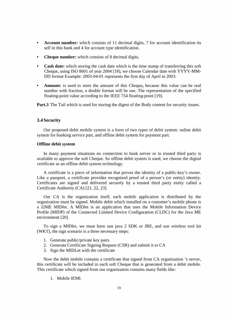
19
• Account number: which consists of 11 decimal digits, 7 for account identification its self in this bank and 4 for account type identification.
• Cheque number: which consists of 8 decimal digits.
• Cash date: which storing the cash date which is the time stamp of transferring this soft Cheque, using ISO 8601 of year 2004 [18], we choose Calendar date with YYYY-MM-DD format Example: 2003-04-01 represents the first day of April in 2003.
• Amount: is used to store the amount of this Cheque, because this value can be real number with fraction, a double format will be use. The representation of the specified floating-point value according to the IEEE 754 floating-point [19].
Part.3 The Tail which is used for storing the digest of the Body content for security issues.
3.4 Security
Our proposed debit mobile system is a form of two types of debit system: online debit system for banking service part, and offline debit system for payment part.
Offline debit system
In many payment situations no connection to bank server or to trusted third party is available to approve the soft Cheque. So offline debit system is used, we choose the digital certificate as an offline debit system technology.
A certificate is a piece of information that proves the identity of a public-key’s owner. Like a passport, a certificate provides recognized proof of a person’s (or entity) identity. Certificates are signed and delivered securely by a trusted third party entity called a Certificate Authority (CA) [21, 22, 23].
Our CA is the organization itself, each mobile application is distributed by the organization must be signed. Mobile debit which installed on a customer’s mobile phone is a J2ME MIDlet. A MIDlet is an application that uses the Mobile Information Device Profile (MIDP) of the Connected Limited Device Configuration (CLDC) for the Java ME environment [20].
To sign a MIDlet, we must have sun java 2 SDK or JRE, and sun wireless tool kit (WKT), the sign scenario is a three necessary steps:
1. Generate public/private key pairs 2. Generate Certificate Signing Request (CSR) and submit it to CA 3. Sign the MIDLet with the certificate
Now the debit mobile contains a certificate that signed from CA organization ‘s server, this certificate will be included in each soft Cheque that is generated from a debit mobile. This certificate which signed from our organization contains many fields like:
1. Mobile IEMI.
20
2. Mobile public key. 3. The certificate start date. 4. The certificate expire date. 5. The organization CA’s signature of this certificate (the organization encrypts the
customer’s certificate digest with its primary key).
To be sure, the certificate of a debit mobile is not altered, it is digested using a hash algorithm [24, 25, 26, 27, 28, 29], and this digest is encrypted with an organization’s private key, which corresponding public key is available to all debit mobile, by an authorization security mode on Bluetooth device, a device can request remote mobile’s IEMI .
The certificate validation process contains:
1. Validity period of the certificate. 2. The certificate ownership using IEMI match. 3. The certificate has been signed with CA organization’s server. 4. The certificate has not been altered using digest technique.
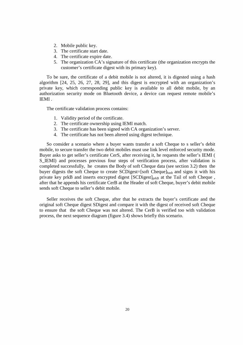
So consider a scenario where a buyer wants transfer a soft Cheque to s seller’s debit mobile, to secure transfer the two debit mobiles must use link level enforced security mode. Buyer asks to get seller’s certificate CerS, after receiving it, he requests the seller’s IEMI ( S_IEMI) and processes previous four steps of verification process, after validation is completed successfully, he creates the Body of soft Cheque data (see section 3.2) then the buyer digests the soft Cheque to create SCDigest=[soft Cheque]hash and signs it with his private key prkB and inserts encrypted digest [SCDigest]prkB at the Tail of soft Cheque , after that he appends his certificate CerB at the Header of soft Cheque, buyer’s debit mobile sends soft Cheque to seller’s debit mobile.
Seller receives the soft Cheque, after that he extracts the buyer’s certificate and the
original soft Cheque digest SDigest and compare it with the digest of received soft Cheque to ensure that the soft Cheque was not altered. The CerB is verified too with validation process, the next sequence diagram (figure 3.4) shows briefly this scenario.
21
Figure (3.4): Transfer soft Cheque scenario.
Buyer's debit
mobile
Seller's debit
mobile
1: Request
Certificate
2: CerS
3: Request IEMI
4: S_IEMI
5: Validate CerS
6: [CerS is valid]
generate Soft
cheque (SC)
7: Send Soft
cheque (SC)
8: Request IEMI
9: B_IEMI
10: validate SC
11: [SC is valide]
store SC
22
In the same way the certifications is validate between customer’s debit mobile and bank server in cash Cheque transaction, when hand checking is completed, the soft Cheque SC is accepted and received on bank server side, because the soft Cheque editor (Buyer’s debit mobile) is a member of bank’s customers, the bank server extracts IEMI code and account number from received soft Cheque certificate, compare them with data stored in its mobile information database.
3.5 Speaker verification system
A speaker recognition/verification process consists two main steps: features extraction, and features matching.
Feature extraction: is a special form of dimensionality reduction, in other words convert the speech waveform to some type of parametric representation [30].
To select the proper one algorithm for feature extraction, we search about a one that can be implemented effectively to work on a mobile device. The mobile phone is a personal device, so we need to develop a speaker verification rather than a speaker identification, because the last one needs more computation and size to store all data speakers[30], note that we will develop a system for speaker verification works completely on mobile device.
In another hand we choose our system to be text-independent rather than text-dependent, which gives more flexibility and user is not forced to remember a phrase[31]. Any speaker verification system is a closed-set since all speakers are known.
In digital processing of speech signals there are many algorithms developed for feature extraction purpose like: Linear Prediction Coding (LPC) [32], Mel frequency Cepstral Coefficients (MFCCs) [33], Perceptual Linear Prediction (PLP) [34].
There are attributes must be in the extracted features to be considered desirable for speaker recognition automatic system [35] as:
• Occur naturally and frequently in speech • Easily measurable • Not change over time or be affected by speaker’s health • Not be affected by reasonable background noise nor depend on specific
transmission characteristics • Not be subject to mimicry
For more than three decades the MFCC algorithm is the popular one for extract speaker features[36][37][38] and became a standard algorithm for this purpose especially for mobile devices as The European Telecommunications Standards Institute (ETSI). All of these reasons motive us to choose MFCCs algorithm for extracting speech signal features. MFCCs as the most spectrum techniques is the most effective in automatic speaker recognition system.
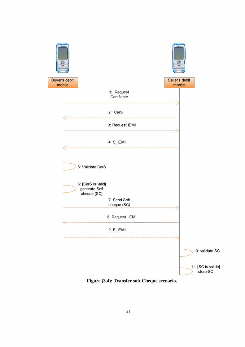
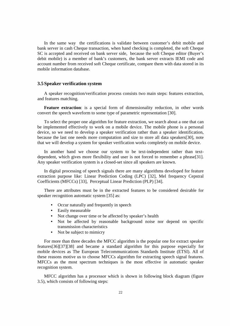
MFCC algorithm has a processor which is shown in following block diagram (figure 3.5), which consists of following steps:
23
• Frame blocking • Windowing using hamming window • Discrete Fourier transform using Radix-4 Fast Fourier transform (FFT) • Mel-frequency wrapping by Mel frequency spaced filter banks • Cepstral Coefficients
Figure (3.5): MFCC processor block diagram.
24
Features clustering: we successfully extracted 18 MFCC features, which means hundreds of records with 18 attributes, this stills a lot of data, but by adding additional block in speaker verification system we can reduce the amount of data by clustering it, this means increasing in insert voice print process time (training) that happens once when deploying and installing the application on mobile device versus decreasing in login process time (testing) that happens each time a user start the application.
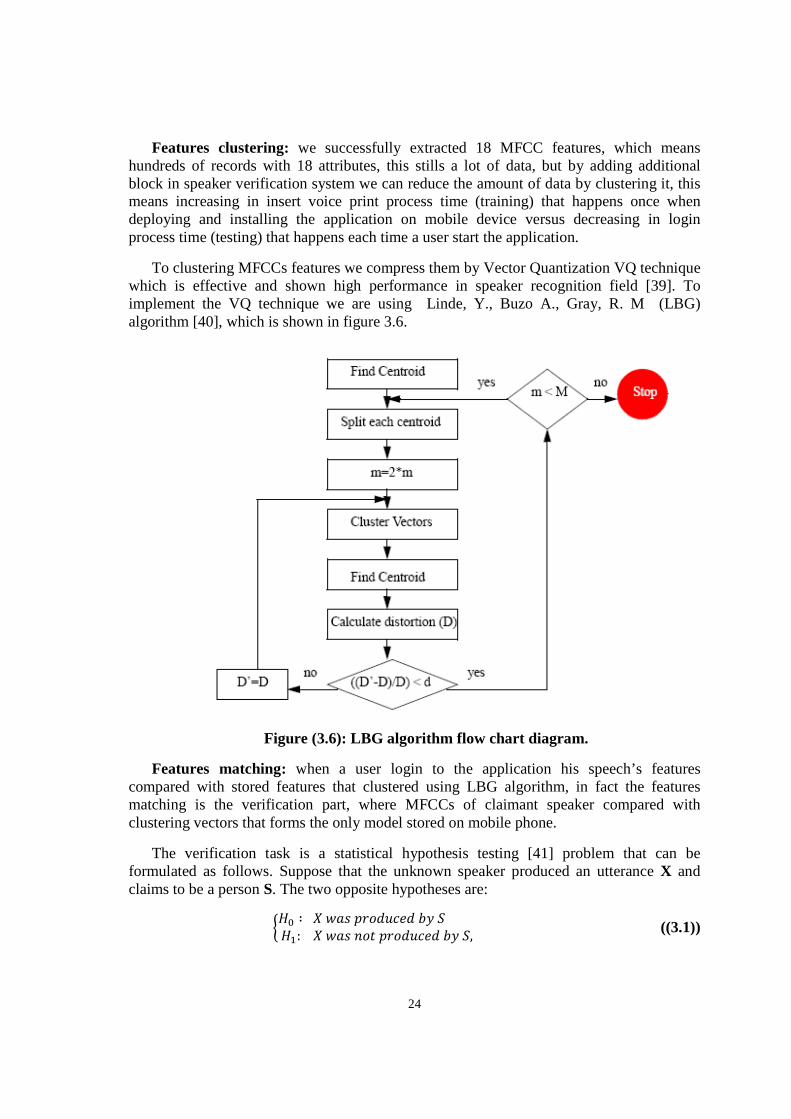
To clustering MFCCs features we compress them by Vector Quantization VQ technique which is effective and shown high performance in speaker recognition field [39]. To implement the VQ technique we are using Linde, Y., Buzo A., Gray, R. M (LBG) algorithm [40], which is shown in figure 3.6.
Figure (3.6): LBG algorithm flow chart diagram.
Features matching: when a user login to the application his speech’s features compared with stored features that clustered using LBG algorithm, in fact the features matching is the verification part, where MFCCs of claimant speaker compared with clustering vectors that forms the only model stored on mobile phone.
The verification task is a statistical hypothesis testing [41] problem that can be formulated as follows. Suppose that the unknown speaker produced an utterance X and claims to be a person S. The two opposite hypotheses are:
��� ∶ ������ ��������:��������� ������, ((3.1))
25
and the verification engine must choose one of them to be true.
Suppose for a given moment of the time that the likelihoods of both hypotheses are known. In this case, the likelihood ratio [42] gives the optimal decision in Bayes sense (minimum risk classification) [42, 43]. The decision rule is then
Decide � ��, ������,��> Θ���,������,��≤ Θ� ((3.2))
where ����,�� is the ratio of the likelihoods of the two hypotheses, and ΘS is a decision threshold
for speaker S. The thresholds Θi are determined from the training data so that a desired balance
between false acceptances (FA) and false rejections (FR) is obtained. The threshold can be global
for all speakers, or it can be speaker-depended [44].
The data for speaker verification is obtained in the form of acoustic feature vectors {xi}
extracted from real speech utterances. In the enrollment phase, a speaker model is trained from the training vectors. In the
verification phase, the input utterance is first converted into feature vectors, which are then used for estimating the likelihoods of the two hypotheses H0 and H1.
The likelihood of the null hypothesis H0 is estimated by matching the vectors X = {xi} against the claimed speaker’s model S, which is intuitively reasonable. Suppose that the probability density of the claimant’s feature vectors p(x|S) is known; in this case, the matching is carried out by computing the likelihood p(X|S) under some simplifying assumptions (independence of the test vectors). In reality, due to finite amount of training data, the densities are only estimates of the true underlying distributions.
The estimation of the likelihood of the alternative hypothesis H1 is considerably much
harder. Estimating this is equivalent to solving what is the likelihood that anyone else in the world (except S) produced X. In speaker recognition community, there have emerged two main approaches for modeling the alternative hypothesis [45], so-called world model and cohort model approaches.
The world model W (background model, universal background model, global speaker
model) is a large model that aims characterizing all possible speakers and speaking contexts of the “world”. It is trained from a large amount (several hours) of speech data from a variety of speakers. Estimating the likelihood of H1 then translates simply to computing the likelihood p(X|W) similarly as with the client model.
The second approach for estimating the likelihood of H1 uses the concept of cohort
models [46]. Rather than modeling the whole world, cohort approach uses a small representative set of models, called cohort set. Individual cohort models’ scores are obtained and combined e.g. by averaging.
26
We use in our verification system a threshold distance, that if feature vectors (user model) are close enough to that features belong to claimed speaker, close less than a given threshold then claimed speaker is accepted else is rejected.
We use Euclidean distance as a distance measurement, and averaging cohort set concept, we have the following equation, where n the size of cohort set, Eucdistanceclaimant
is the distance between speaker model and that extracted from claimant, and EucDistancecohort(i) is the distance between speaker model and ith cohort speaker model.
����� = � ������������������
�∑ �������������(�)
�
�
��
((3.3))
So if this ratio is less than a given threshold, then claimant speaker is accepted, else he is rejected.
3.6 System requirements specification (SRS)
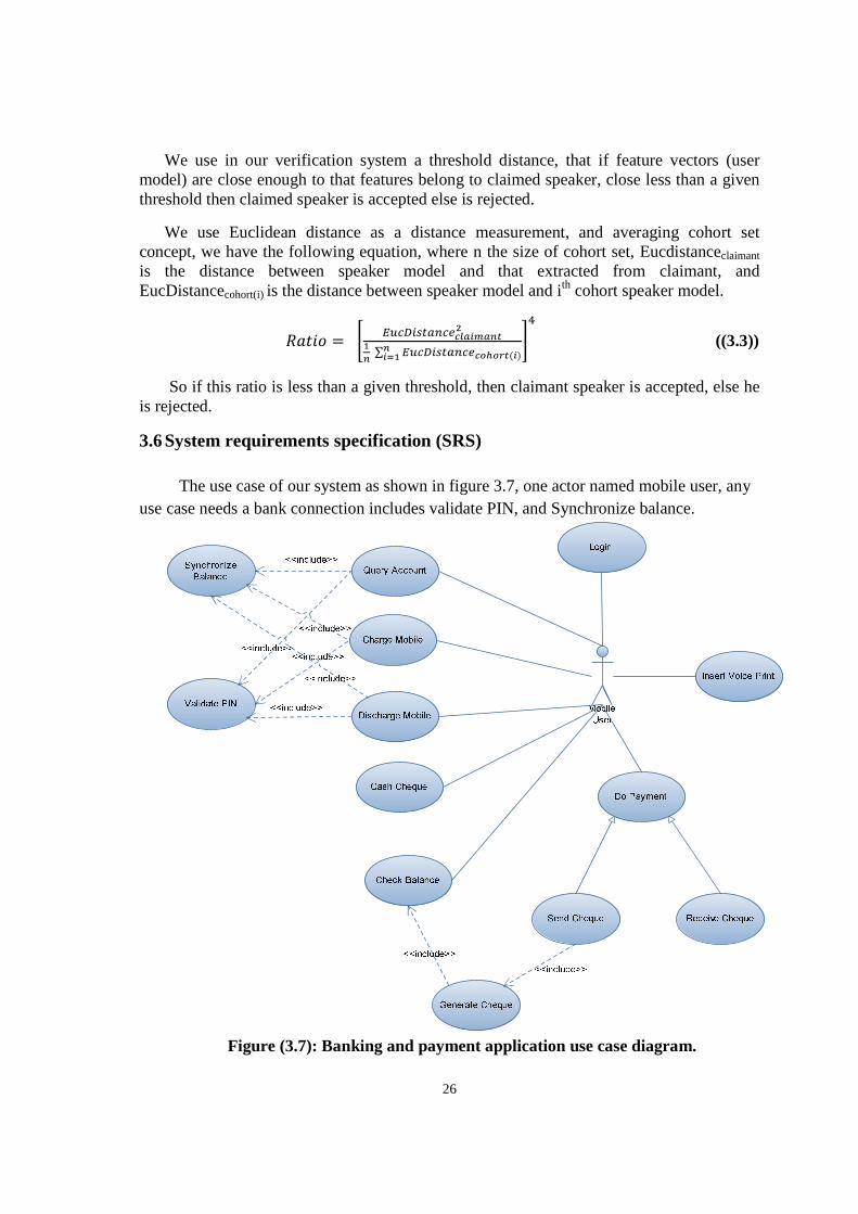
The use case of our system as shown in figure 3.7, one actor named mobile user, any use case needs a bank connection includes validate PIN, and Synchronize balance.
Figure (3.7): Banking and payment application use case diagram.
27
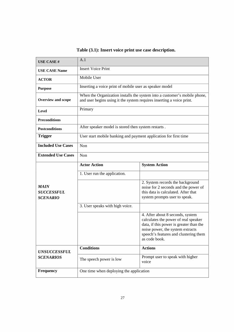
Table (3.1): Insert voice print use case description.
USE CASE # A.1
USE CASE Name Insert Voice Print
ACTOR Mobile User
Purpose Inserting a voice print of mobile user as speaker model
Overview and scope When the Organization installs the system into a customer’s mobile phone, and user begins using it the system requires inserting a voice print.
Level Primary
Preconditions
Postconditions After speaker model is stored then system restarts .
Trigger User start mobile banking and payment application for first time
Included Use Cases Non
Extended Use Cases Non
MAIN SUCCESSFUL SCENARIO
Actor Action System Action
1. User run the application.
2. System records the background noise for 2 seconds and the power of this data is calculated. After that system prompts user to speak.
3. User speaks with high voice.
4. After about 8 seconds, system calculates the power of real speaker data, if this power is greater than the noise power, the system extracts speech’s features and clustering them as code book.
UNSUCCESSFUL SCENARIOS
Conditions Actions
The speech power is low Prompt user to speak with higher voice
Frequency One time when deploying the application
28
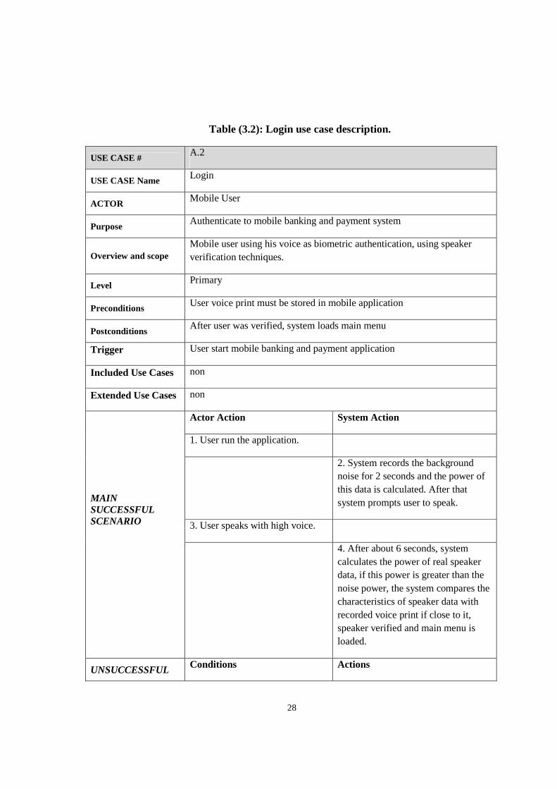
Table (3.2): Login use case description.
USE CASE # A.2
USE CASE Name Login
ACTOR Mobile User
Purpose Authenticate to mobile banking and payment system
Overview and scope Mobile user using his voice as biometric authentication, using speaker verification techniques.
Level Primary
Preconditions User voice print must be stored in mobile application
Postconditions After user was verified, system loads main menu
Trigger User start mobile banking and payment application
Included Use Cases non
Extended Use Cases non
MAIN SUCCESSFUL SCENARIO
Actor Action System Action
1. User run the application.
2. System records the background noise for 2 seconds and the power of this data is calculated. After that system prompts user to speak.
3. User speaks with high voice.
4. After about 6 seconds, system calculates the power of real speaker data, if this power is greater than the noise power, the system compares the characteristics of speaker data with recorded voice print if close to it, speaker verified and main menu is loaded.
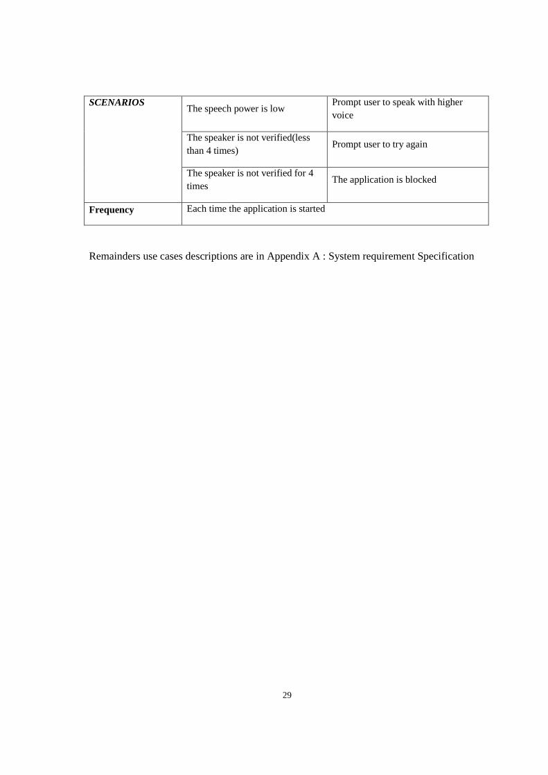
UNSUCCESSFUL Conditions Actions
29
SCENARIOS The speech power is low
Prompt user to speak with higher voice
The speaker is not verified(less than 4 times)
Prompt user to try again
The speaker is not verified for 4 times
The application is blocked
Frequency Each time the application is started
Remainders use cases descriptions are in Appendix A : System requirement Specification
30
Chapter 4
SYSTEM ANALYSIS MODEL
4.1 Static model
In software engineering static model describes the static structural of system, that reflects the problem domain [47]. In static model we use class diagram concept [48] to define class’s attributes and relations between them later in section 5.4 Class design we will define the operations for each class, class diagram build on UML is a powerful tool for detailed description [49, 50].
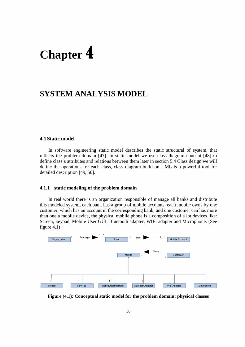
4.1.1 static modeling of the problem domain
In real world there is an organization responsible of manage all banks and distribute this modeled system, each bank has a group of mobile accounts, each mobile owns by one customer, which has an account in the corresponding bank, and one customer can has more than one a mobile device, the physical mobile phone is a composition of a lot devices like: Screen, keypad, Mobile User GUI, Bluetooth adapter, WIFI adapter and Microphone. (See figure 4.1)
Figure (4.1): Conceptual static model for the problem domain: physical classes
Bank Mobile AccountHas
Mobile
Screen KeyPad MobileUserInterfcae BluetoothAdapter WIFIAdapter
1 1...*
1 1 1 1 1
Microphone
1
OrganizationManages1
1...*
Customer* 1
Owns
31
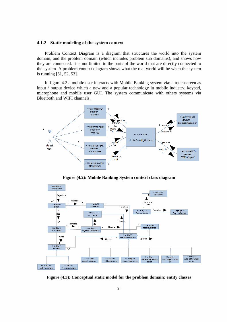
4.1.2 Static modeling of the system context
Problem Context Diagram is a diagram that structures the world into the system domain, and the problem domain (which includes problem sub domains), and shows how they are connected. It is not limited to the parts of the world that are directly connected to the system. A problem context diagram shows what the real world will be when the system is running [51, 52, 53].
In figure 4.2 a mobile user interacts with Mobile Banking system via: a touchscreen as input / output device which a new and a popular technology in mobile industry, keypad, microphone and mobile user GUI. The system communicate with others systems via Bluetooth and WIFI channels.
Figure (4.2): Mobile Banking System context class diagram
Figure (4.3): Conceptual static model for the problem domain: entity classes
32
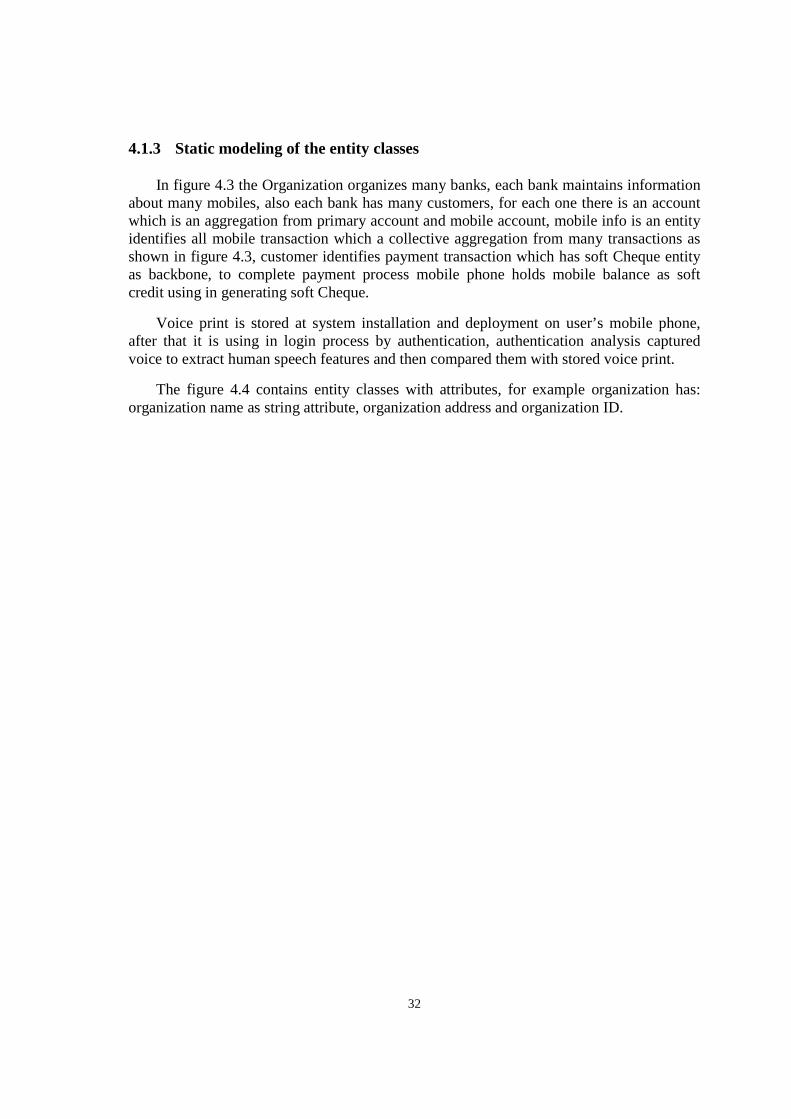
4.1.3 Static modeling of the entity classes
In figure 4.3 the Organization organizes many banks, each bank maintains information about many mobiles, also each bank has many customers, for each one there is an account which is an aggregation from primary account and mobile account, mobile info is an entity identifies all mobile transaction which a collective aggregation from many transactions as shown in figure 4.3, customer identifies payment transaction which has soft Cheque entity as backbone, to complete payment process mobile phone holds mobile balance as soft credit using in generating soft Cheque.
Voice print is stored at system installation and deployment on user’s mobile phone, after that it is using in login process by authentication, authentication analysis captured voice to extract human speech features and then compared them with stored voice print.
The figure 4.4 contains entity classes with attributes, for example organization has: organization name as string attribute, organization address and organization ID.
33
Figure (4.4): Conceptual static model for the Mobile Banking system: class attributes
4.2 Object structuring
4.2.1 Major subsystem
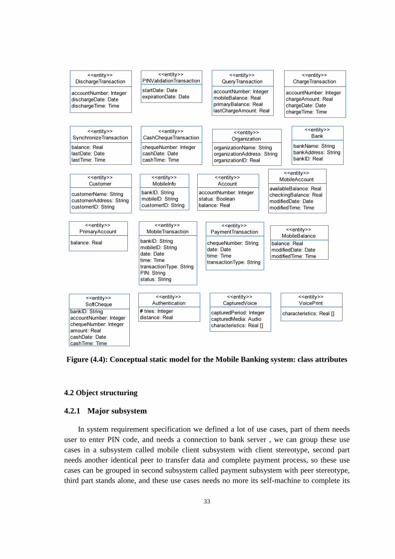
In system requirement specification we defined a lot of use cases, part of them needs user to enter PIN code, and needs a connection to bank server , we can group these use cases in a subsystem called mobile client subsystem with client stereotype, second part needs another identical peer to transfer data and complete payment process, so these use cases can be grouped in second subsystem called payment subsystem with peer stereotype, third part stands alone, and these use cases needs no more its self-machine to complete its
<<entity>>
Bank
bankName: String
bankAddress: String
bankID: Real
<<entity>>
Organization
organizationName: String
organizationAddress: String
organizationID: Real
<<entity>>
Customer
customerName: String
customerAddress: String
customerID: String
<<entity>>
MobileInfo
bankID: String
mobileID: String
customerID: String
<<entity>>
MobileTransaction
bankID: String
mobileID: String
date: Date
time: Time
transactionType: String
PIN: String
status: String
<<entity>>
Account
accountNumber: Integer
status: Boolean
balance: Real
<<entity>>
PrimaryAccount
balance: Real
<<entity>>
MobileAccount
availableBalance: Real
checkingBalance: Real
modifiedDate: Date
modifiedTime: Time
<<entity>>
MobileBalance
balance: Real
modifiedDate: Date
modifiedTime: Time
<<entity>>
PaymentTransaction
chequeNumber: String
date: Date
time: Time
transactionType: String
<<entity>>
SoftCheque
bankID: String
accountNumber: Integer
chequeNumber: Integer
amount: Real
cashDate: Date
cashTime: Time
<<entity>>
PINValidationTransaction
startDate: Date
expirationDate: Date
<<entity>>
QueryTransaction
accountNumber: Integer
mobileBalance: Real
primaryBalance: Real
lastChargeAmount: Real
<<entity>>
ChargeTransaction
accountNumber: Integer
chargeAmount: Real
chargeDate: Date
chargeTime: Time
<<entity>>
CashChequeTransaction
chequeNumber: Integer
cashDate: Date
cashTime: Time
<<entity>>
DischargeTransaction
accountNumber: Integer
dischargeDate: Date
dischargeTime: Time
<<entity>>
Authentication
# tries: Integer
distance: Real
<<entity>>
VoicePrint
characteristics: Real []
<<entity>>
CapturedVoice
capturedPeriod: Integer
capturedMedia: Audio
characteristics: Real []
<<entity>>
SynchronizeTransaction
balance: Real
lastDate: Date
lastTime: Time
34
scenario these are: insert voice print and login use cases, which we grouped them in third software subsystem called authentication with shortly DSP stereotype. The last subsystem is a service subsystem called mobile banking service subsystem which is necessary to complete mobile transactions and cash Cheque transaction, the structure of these subsystems is shown in figure 4.5 .
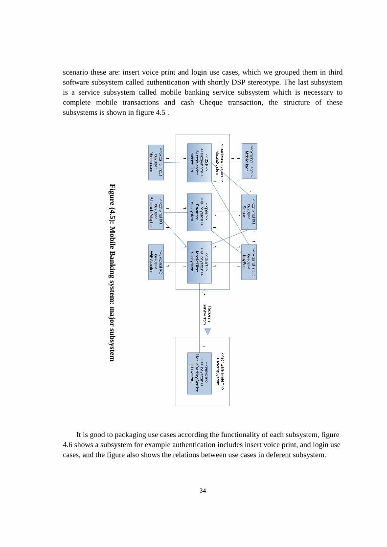
It is good to packaging use cases according the functionality of each subsystem, figure 4.6 shows a subsystem for example authentication includes insert voice print, and login use cases, and the figure also shows the relations between use cases in deferent subsystem.
Figure (4.5): M
obile Banking system
: major subsystem
35
4.2.2 Mobile subsystems object structuring: interface objects
The figure 4.7 briefly describes Mobile System external and boundary classes, our mobile system interacts with the world with input/output devices like: keypad, screen and others, and communicates with user via Mobile User Interaction object
Figure (4.6): subsystem
packaging of use cases
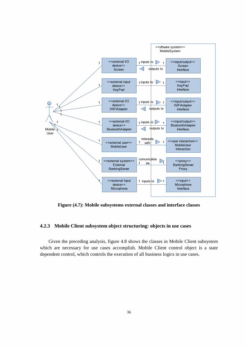
36
Figure (4.7): Mobile subsystems external classes and interface classes
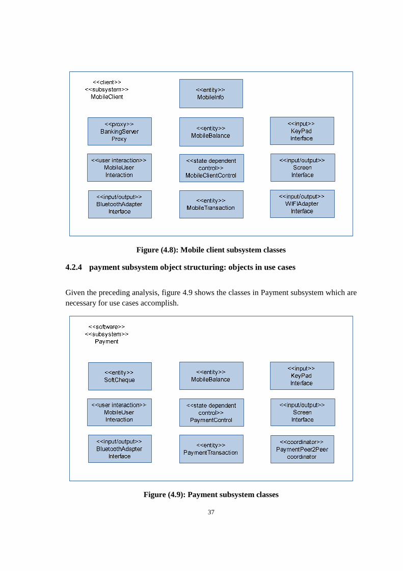
4.2.3 Mobile Client subsystem object structuring: objects in use cases
Given the preceding analysis, figure 4.8 shows the classes in Mobile Client subsystem which are necessary for use cases accomplish. Mobile Client control object is a state dependent control, which controls the execution of all business logics in use cases.
<<input/output>>
Screen
Interface
<<input>>
KeyPad
Interface
<<input/output>>
WIFIAdapter
Interface
<<input/output>>
BluetoothAdapter
Interface
<<user interaction>>
MobileUser
Interaction
<<proxy>>
BankingServer
Proxy
<<sftware system>>
MobileSystem
<<external I/O
device>>
Screen
<<external input
device>>
KeyPad
<<external I/O
device>>
WIFIAdapter
<<external I/O
device>>
BluetoothAdapter
<<external user>>
MobileUser
<<external system>>
External
BankingServer
Mobile
User
1 1
11
1 1
1 1
1 1
11 inputs to
outputs to
inputs to
inputs to
outputs to
inputs to
outputs to
interacts
with
comunicates
via
1
1
1
1
1
1
1
1
1
1
1
1
<<input>>
Microphone
Interface
<<external input
device>>
Microphone
inputs to1 11
1
37
Figure (4.8): Mobile client subsystem classes
4.2.4 payment subsystem object structuring: objects in use cases
Given the preceding analysis, figure 4.9 shows the classes in Payment subsystem which are necessary for use cases accomplish.
Figure (4.9): Payment subsystem classes
38
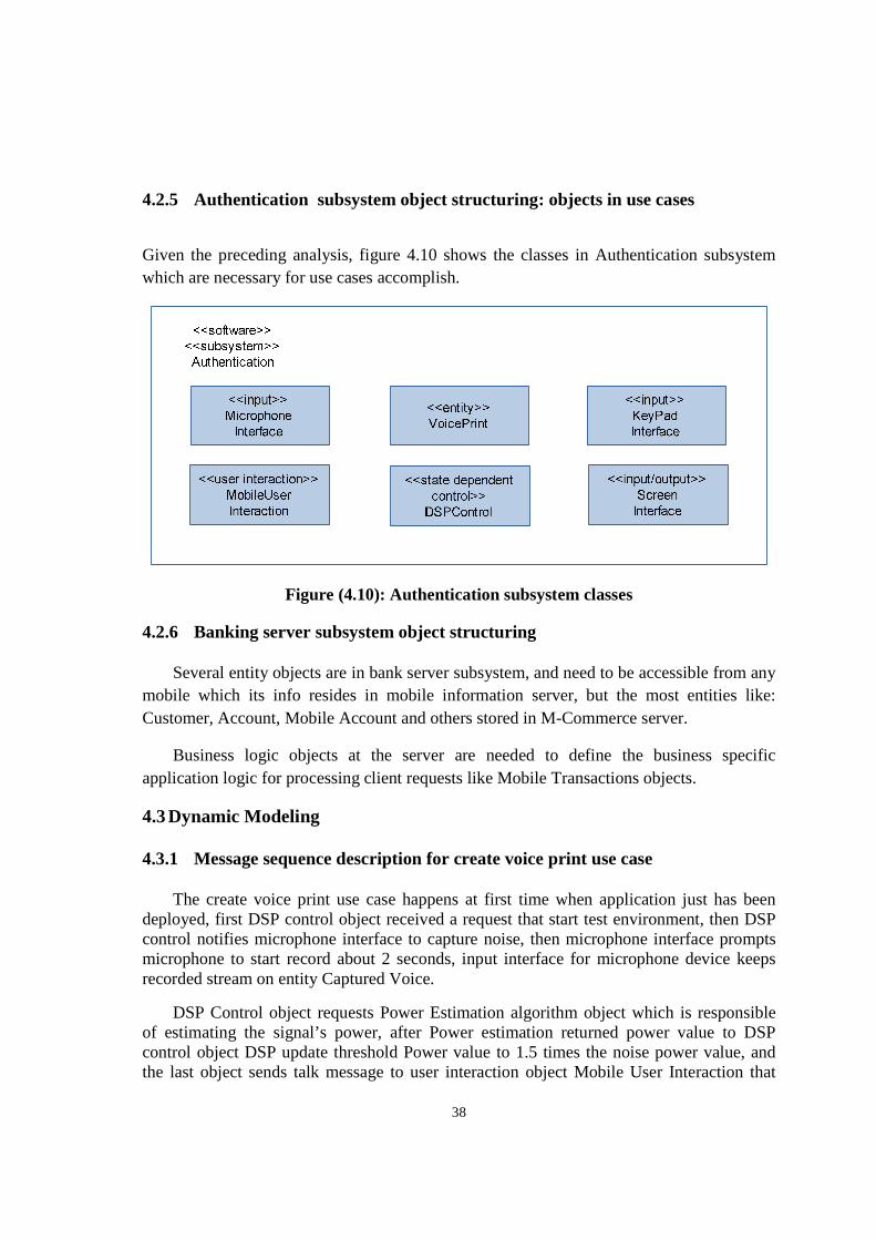
4.2.5 Authentication subsystem object structuring: objects in use cases
Given the preceding analysis, figure 4.10 shows the classes in Authentication subsystem which are necessary for use cases accomplish.
Figure (4.10): Authentication subsystem classes
4.2.6 Banking server subsystem object structuring
Several entity objects are in bank server subsystem, and need to be accessible from any mobile which its info resides in mobile information server, but the most entities like: Customer, Account, Mobile Account and others stored in M-Commerce server.
Business logic objects at the server are needed to define the business specific application logic for processing client requests like Mobile Transactions objects.
4.3 Dynamic Modeling
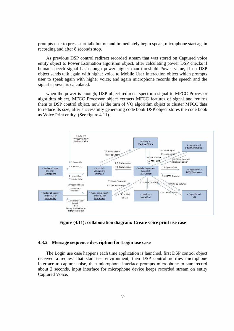
4.3.1 Message sequence description for create voice print use case
The create voice print use case happens at first time when application just has been deployed, first DSP control object received a request that start test environment, then DSP control notifies microphone interface to capture noise, then microphone interface prompts microphone to start record about 2 seconds, input interface for microphone device keeps recorded stream on entity Captured Voice.
DSP Control object requests Power Estimation algorithm object which is responsible of estimating the signal’s power, after Power estimation returned power value to DSP control object DSP update threshold Power value to 1.5 times the noise power value, and the last object sends talk message to user interaction object Mobile User Interaction that
39
prompts user to press start talk button and immediately begin speak, microphone start again recording and after 8 seconds stop.
As previous DSP control redirect recorded stream that was stored on Captured voice entity object to Power Estimation algorithm object, after calculating power DSP checks if human speech signal has enough power higher than threshold Power value, if no DSP object sends talk again with higher voice to Mobile User Interaction object which prompts user to speak again with higher voice, and again microphone records the speech and the signal’s power is calculated.
when the power is enough, DSP object redirects spectrum signal to MFCC Processor algorithm object, MFCC Processor object extracts MFCC features of signal and returns them to DSP control object, now is the turn of VQ algorithm object to cluster MFCC data to reduce its size, after successfully generating code book DSP object stores the code book as Voice Print entity. (See figure 4.11).
Figure (4.11): collaboration diagram: Create voice print use case
4.3.2 Message sequence description for Login use case
The Login use case happens each time application is launched, first DSP control object received a request that start test environment, then DSP control notifies microphone interface to capture noise, then microphone interface prompts microphone to start record about 2 seconds, input interface for microphone device keeps recorded stream on entity Captured Voice.
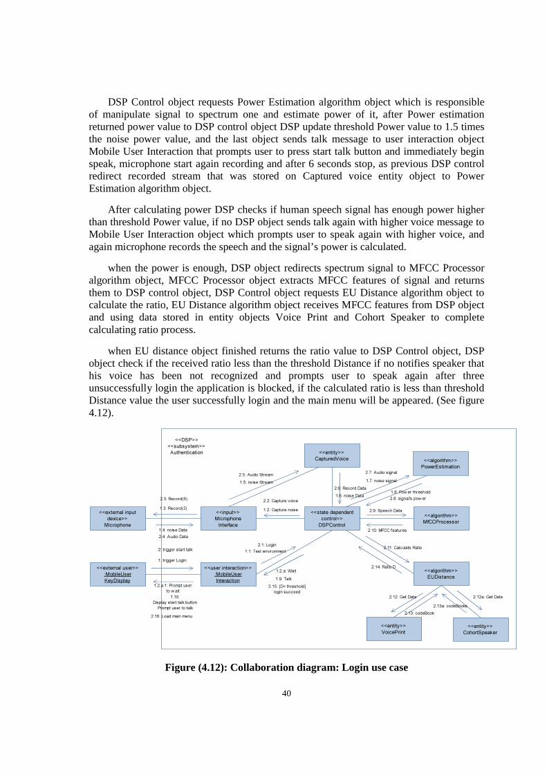
40
DSP Control object requests Power Estimation algorithm object which is responsible of manipulate signal to spectrum one and estimate power of it, after Power estimation returned power value to DSP control object DSP update threshold Power value to 1.5 times the noise power value, and the last object sends talk message to user interaction object Mobile User Interaction that prompts user to press start talk button and immediately begin speak, microphone start again recording and after 6 seconds stop, as previous DSP control redirect recorded stream that was stored on Captured voice entity object to Power Estimation algorithm object.
After calculating power DSP checks if human speech signal has enough power higher than threshold Power value, if no DSP object sends talk again with higher voice message to Mobile User Interaction object which prompts user to speak again with higher voice, and again microphone records the speech and the signal’s power is calculated.
when the power is enough, DSP object redirects spectrum signal to MFCC Processor algorithm object, MFCC Processor object extracts MFCC features of signal and returns them to DSP control object, DSP Control object requests EU Distance algorithm object to calculate the ratio, EU Distance algorithm object receives MFCC features from DSP object and using data stored in entity objects Voice Print and Cohort Speaker to complete calculating ratio process.
when EU distance object finished returns the ratio value to DSP Control object, DSP object check if the received ratio less than the threshold Distance if no notifies speaker that his voice has been not recognized and prompts user to speak again after three unsuccessfully login the application is blocked, if the calculated ratio is less than threshold Distance value the user successfully login and the main menu will be appeared. (See figure 4.12).
Figure (4.12): Collaboration diagram: Login use case
<<external user>>
:MobileUser
KeyDisplay
<<user interaction>>
:MobileUser
Interaction
<<input>>
Microphone
Interface
<<external input
device>>
Microphone
<<entity>>
CapturedVoice
<<state dependent
control>>
DSPControl
<<entity>>
VoicePrint
1: trigger Login
1.1: Test environment
1.2: Capture noise
1.2.a: Wait
1.2.a.1: Prompt user
to w ait
1.3: Record(2)
1.4: noise Data
1.5: noise Stream
<<algorithm>>
PowerEstimation
<<algorithm>>
MfCCProcessor
1.6: noise Data
1.7: noise signal
1.8: Power threshold
1.9: Talk
1.10:
Display start talk button
Prompt user to talk
2: trigger start talk2.1: Login
2.2: Capture voice2.3: Record(6)
2.5: Audio Stream
2.4: Audio Data
2.6: Record Data
2.7: Audio signal
2.8: signal's pow er
2.9: Speech Data
2.10: MFCC features
<<algorithm>>
EUDistance
2.11: Calculate Ratio
2.14: Ratio D
2.12: Get Data
<<DSP>>
<<subsystem>>
Authentication
2.13: codeBook
2.15: [D< threshold]
login succeed
2.16: Load main menu
<<entity>>
CohortSpeaker
2.12a: Get Data
2.13a: codeBooks
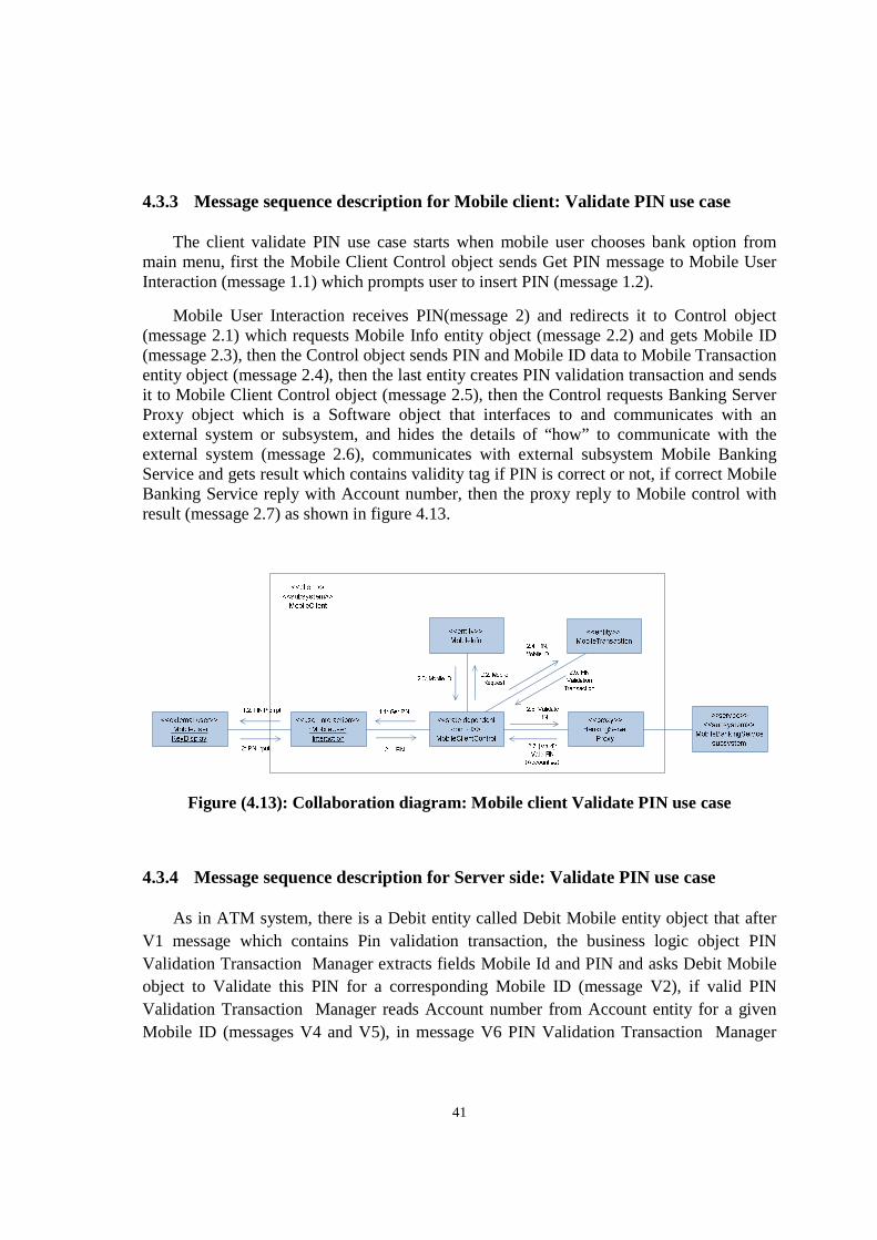
41
4.3.3 Message sequence description for Mobile client: Validate PIN use case
The client validate PIN use case starts when mobile user chooses bank option from main menu, first the Mobile Client Control object sends Get PIN message to Mobile User Interaction (message 1.1) which prompts user to insert PIN (message 1.2).
Mobile User Interaction receives PIN(message 2) and redirects it to Control object (message 2.1) which requests Mobile Info entity object (message 2.2) and gets Mobile ID (message 2.3), then the Control object sends PIN and Mobile ID data to Mobile Transaction entity object (message 2.4), then the last entity creates PIN validation transaction and sends it to Mobile Client Control object (message 2.5), then the Control requests Banking Server Proxy object which is a Software object that interfaces to and communicates with an external system or subsystem, and hides the details of “how” to communicate with the external system (message 2.6), communicates with external subsystem Mobile Banking Service and gets result which contains validity tag if PIN is correct or not, if correct Mobile Banking Service reply with Account number, then the proxy reply to Mobile control with result (message 2.7) as shown in figure 4.13.
Figure (4.13): Collaboration diagram: Mobile client Validate PIN use case
4.3.4 Message sequence description for Server side: Validate PIN use case
As in ATM system, there is a Debit entity called Debit Mobile entity object that after V1 message which contains Pin validation transaction, the business logic object PIN Validation Transaction Manager extracts fields Mobile Id and PIN and asks Debit Mobile object to Validate this PIN for a corresponding Mobile ID (message V2), if valid PIN Validation Transaction Manager reads Account number from Account entity for a given Mobile ID (messages V4 and V5), in message V6 PIN Validation Transaction Manager
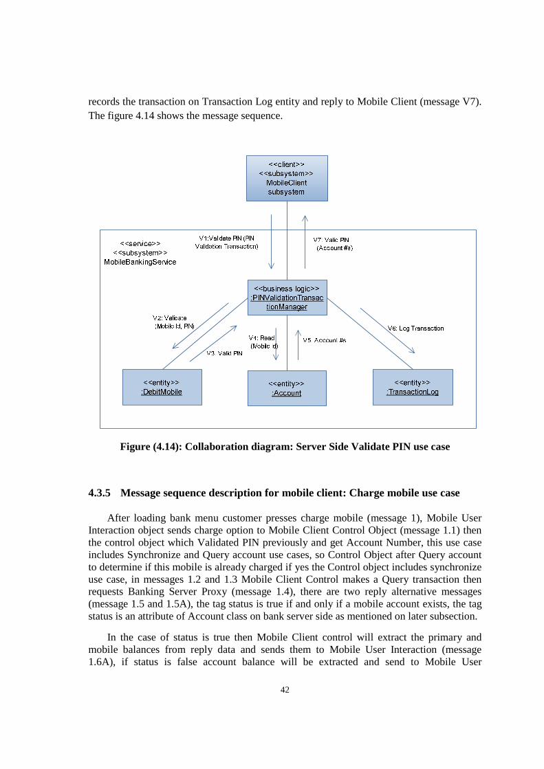
42
records the transaction on Transaction Log entity and reply to Mobile Client (message V7). The figure 4.14 shows the message sequence.
Figure (4.14): Collaboration diagram: Server Side Validate PIN use case
4.3.5 Message sequence description for mobile client: Charge mobile use case
After loading bank menu customer presses charge mobile (message 1), Mobile User Interaction object sends charge option to Mobile Client Control Object (message 1.1) then the control object which Validated PIN previously and get Account Number, this use case includes Synchronize and Query account use cases, so Control Object after Query account to determine if this mobile is already charged if yes the Control object includes synchronize use case, in messages 1.2 and 1.3 Mobile Client Control makes a Query transaction then requests Banking Server Proxy (message 1.4), there are two reply alternative messages (message 1.5 and 1.5A), the tag status is true if and only if a mobile account exists, the tag status is an attribute of Account class on bank server side as mentioned on later subsection.
In the case of status is true then Mobile Client control will extract the primary and mobile balances from reply data and sends them to Mobile User Interaction (message 1.6A), if status is false account balance will be extracted and send to Mobile User
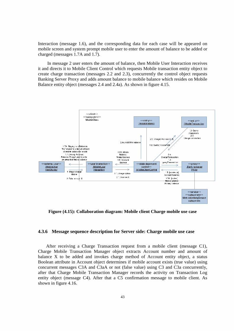
43
Interaction (message 1.6), and the corresponding data for each case will be appeared on mobile screen and system prompt mobile user to enter the amount of balance to be added or charged (messages 1.7A and 1.7).
In message 2 user enters the amount of balance, then Mobile User Interaction receives it and directs it to Mobile Client Control which requests Mobile transaction entity object to create charge transaction (messages 2.2 and 2.3), concurrently the control object requests Banking Server Proxy and adds amount balance to mobile balance which resides on Mobile Balance entity object (messages 2.4 and 2.4a). As shown in figure 4.15.
Figure (4.15): Collaboration diagram: Mobile client Charge mobile use case
4.3.6 Message sequence description for Server side: Charge mobile use case
After receiving a Charge Transaction request from a mobile client (message C1), Charge Mobile Transaction Manager object extracts Account number and amount of balance X to be added and invokes charge method of Account entity object, a status Boolean attribute in Account object determines if mobile account exists (true value) using concurrent messages C3A and C3aA or not (false value) using C3 and C3a concurrently, after that Charge Mobile Transaction Manager records the activity on Transaction Log entity object (message C4). After that a C5 confirmation message to mobile client. As shown in figure 4.16.
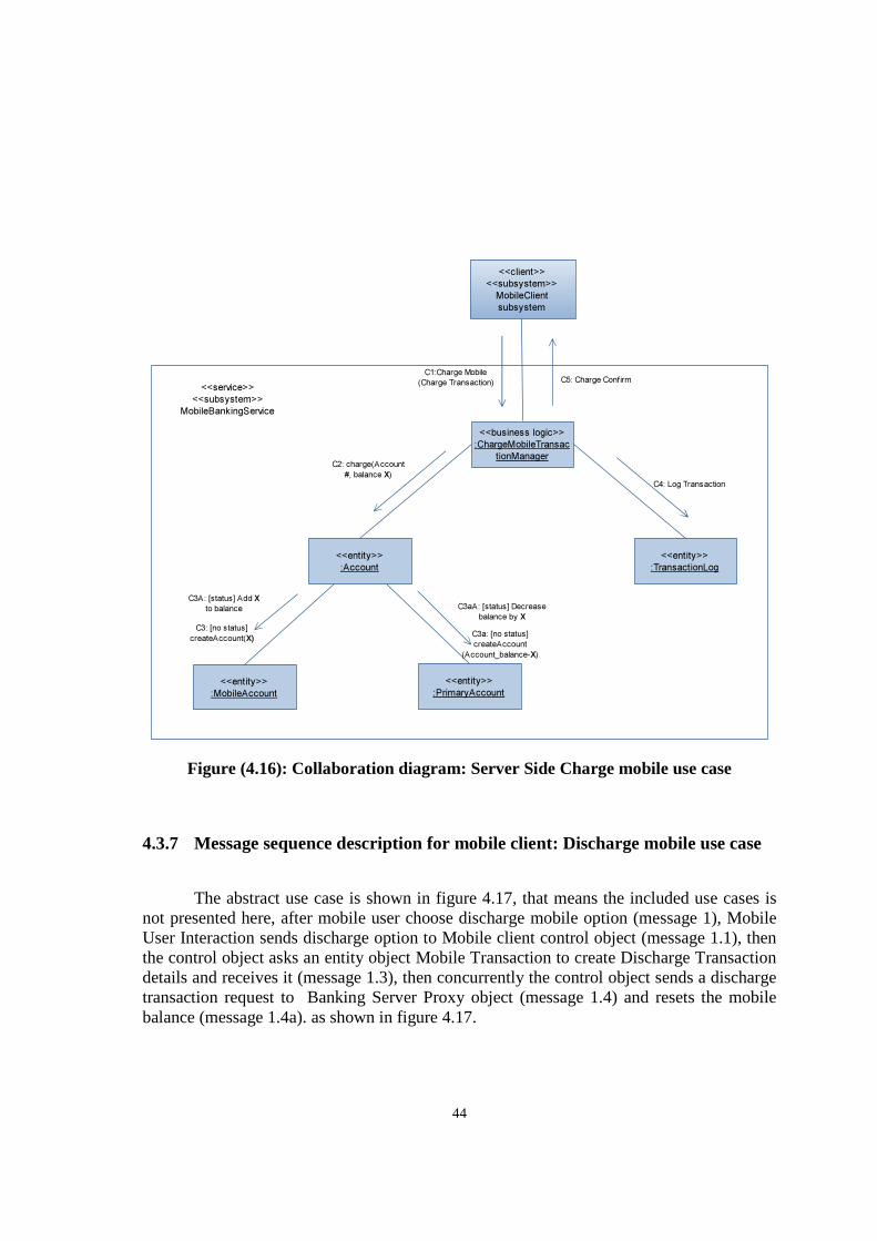
44
Figure (4.16): Collaboration diagram: Server Side Charge mobile use case
4.3.7 Message sequence description for mobile client: Discharge mobile use case
The abstract use case is shown in figure 4.17, that means the included use cases is not presented here, after mobile user choose discharge mobile option (message 1), Mobile User Interaction sends discharge option to Mobile client control object (message 1.1), then the control object asks an entity object Mobile Transaction to create Discharge Transaction details and receives it (message 1.3), then concurrently the control object sends a discharge transaction request to Banking Server Proxy object (message 1.4) and resets the mobile balance (message 1.4a). as shown in figure 4.17.
<<business logic>>
:ChargeMobileTransac
tionManager
<<entity>>
:Account
<<entity>>
:TransactionLog
<<client>>
<<subsystem>>
MobileClient
subsystem
<<service>>
<<subsystem>>
MobileBankingService
C1:Charge Mobile
(Charge Transaction)
C2: charge(Account
#, balance X)
C4: Log Transaction
<<entity>>
:MobileAccount
<<entity>>
:PrimaryAccount
C3: [no status]
createAccount(X)C3a: [no status]
createAccount
(Account_balance-X)
C3A: [status] Add X
to balance C3aA: [status] Decrease
balance by X
C5: Charge Confirm
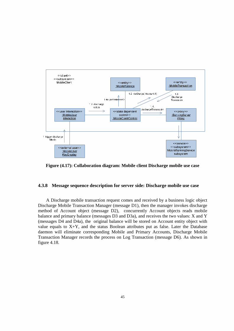
45
Figure (4.17): Collaboration diagram: Mobile client Discharge mobile use case
4.3.8 Message sequence description for server side: Discharge mobile use case
A Discharge mobile transaction request comes and received by a business logic object Discharge Mobile Transaction Manager (message D1), then the manager invokes discharge method of Account object (message D2), concurrently Account objects reads mobile balance and primary balance (messages D3 and D3a), and receives the two values: X and Y (messages D4 and D4a), the original balance will be stored on Account entity object with value equals to X+Y, and the status Boolean attributes put as false. Later the Database daemon will eliminate corresponding Mobile and Primary Accounts, Discharge Mobile Transaction Manager records the process on Log Transaction (message D6). As shown in figure 4.18.
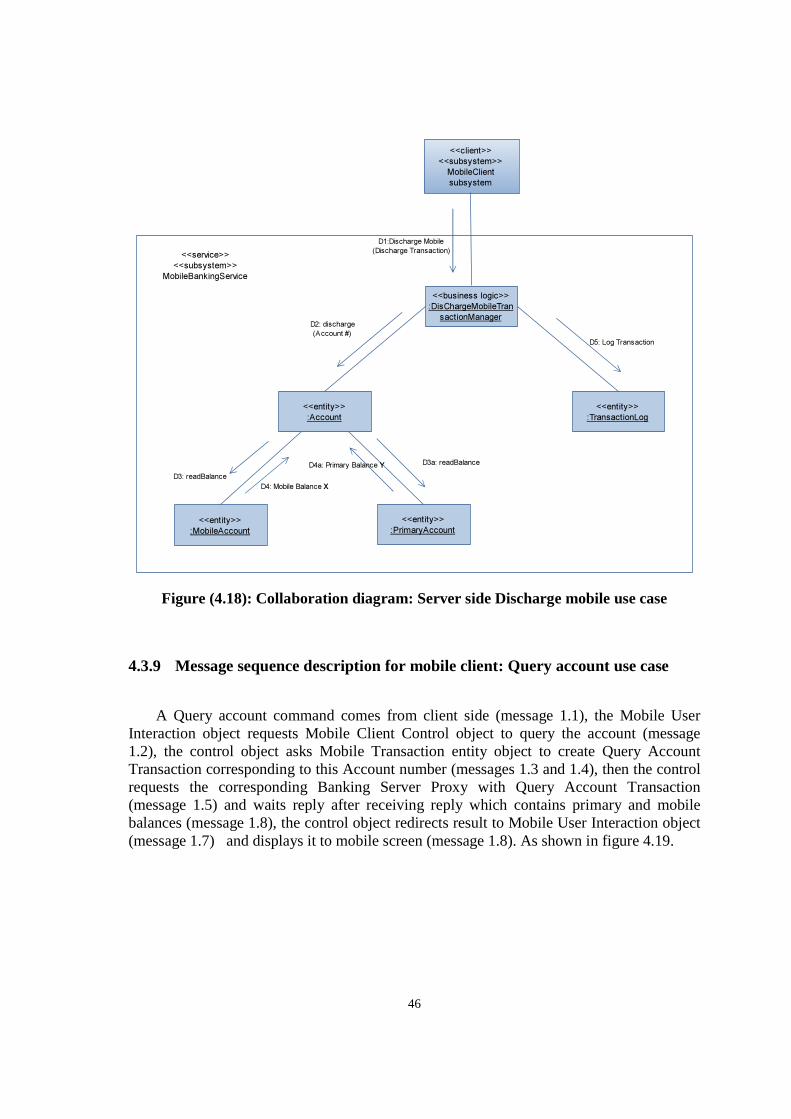
46
Figure (4.18): Collaboration diagram: Server side Discharge mobile use case
4.3.9 Message sequence description for mobile client: Query account use case
A Query account command comes from client side (message 1.1), the Mobile User Interaction object requests Mobile Client Control object to query the account (message 1.2), the control object asks Mobile Transaction entity object to create Query Account Transaction corresponding to this Account number (messages 1.3 and 1.4), then the control requests the corresponding Banking Server Proxy with Query Account Transaction (message 1.5) and waits reply after receiving reply which contains primary and mobile balances (message 1.8), the control object redirects result to Mobile User Interaction object (message 1.7) and displays it to mobile screen (message 1.8). As shown in figure 4.19.
<<business logic>>
:DisChargeMobileTran
sactionManager
<<entity>>
:Account
<<entity>>
:TransactionLog
<<client>>
<<subsystem>>
MobileClient
subsystem
<<service>>
<<subsystem>>
MobileBankingService
D1:Discharge Mobile
(Discharge Transaction)
D2: discharge
(Account #)
D5: Log Transaction
<<entity>>
:MobileAccount
<<entity>>
:PrimaryAccount
D3: readBalance
D3a: readBalance
D4: Mobile Balance X
D4a: Primary Balance Y
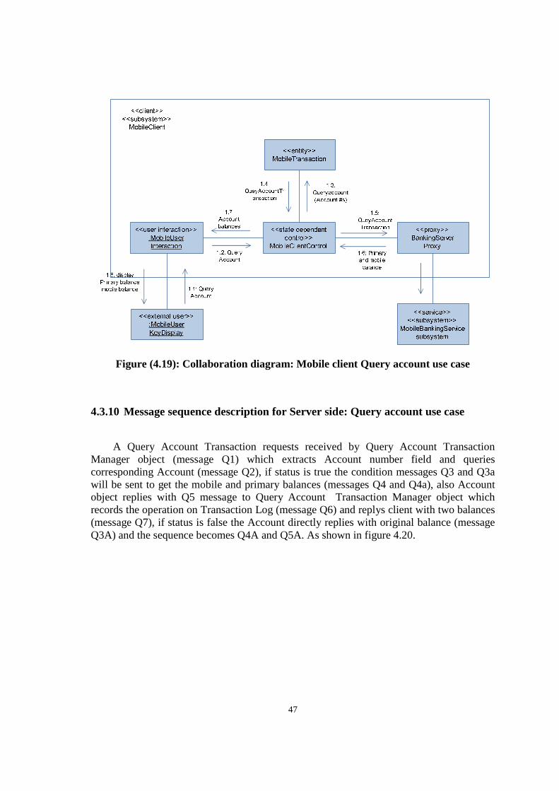
47
Figure (4.19): Collaboration diagram: Mobile client Query account use case
4.3.10 Message sequence description for Server side: Query account use case
A Query Account Transaction requests received by Query Account Transaction Manager object (message Q1) which extracts Account number field and queries corresponding Account (message Q2), if status is true the condition messages Q3 and Q3a will be sent to get the mobile and primary balances (messages Q4 and Q4a), also Account object replies with Q5 message to Query Account Transaction Manager object which records the operation on Transaction Log (message Q6) and replys client with two balances (message Q7), if status is false the Account directly replies with original balance (message Q3A) and the sequence becomes Q4A and Q5A. As shown in figure 4.20.
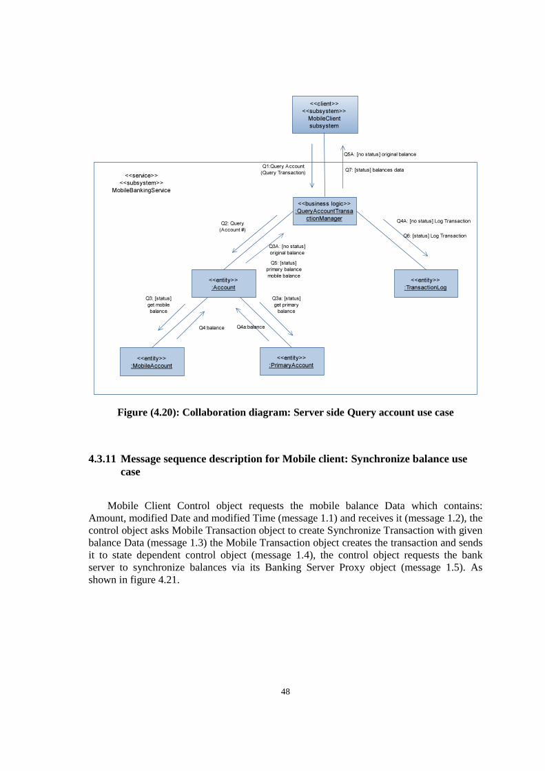
48
Figure (4.20): Collaboration diagram: Server side Query account use case
4.3.11 Message sequence description for Mobile client: Synchronize balance use case
Mobile Client Control object requests the mobile balance Data which contains: Amount, modified Date and modified Time (message 1.1) and receives it (message 1.2), the control object asks Mobile Transaction object to create Synchronize Transaction with given balance Data (message 1.3) the Mobile Transaction object creates the transaction and sends it to state dependent control object (message 1.4), the control object requests the bank server to synchronize balances via its Banking Server Proxy object (message 1.5). As shown in figure 4.21.
<<business logic>>
:QueryAccountTransa
ctionManager
<<entity>>
:Account
<<entity>>
:TransactionLog
<<client>>
<<subsystem>>
MobileClient
subsystem
<<service>>
<<subsystem>>
MobileBankingService
Q1:Query Account
(Query Transaction)
Q2: Query
(Account #)
Q3A: [no status]
original balance
Q6: [status] Log Transaction
<<entity>>
:MobileAccount
<<entity>>
:PrimaryAccount
Q3: [status]
get mobile
balance
Q4:balance Q4a:balance
Q3a: [status]
get primary
balance
Q5: [status]
primary balance
mobile balance
Q7: [status] balances data
Q4A: [no status] Log Transaction
Q5A: [no status] original balance
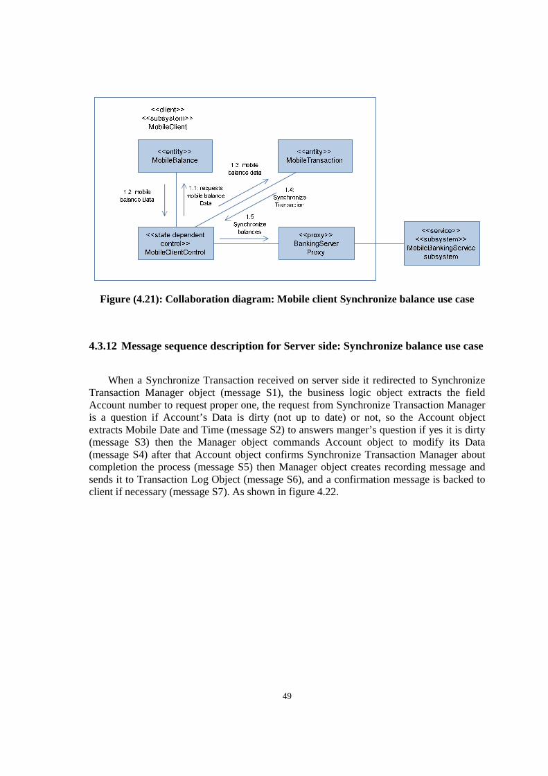
49
Figure (4.21): Collaboration diagram: Mobile client Synchronize balance use case
4.3.12 Message sequence description for Server side: Synchronize balance use case
When a Synchronize Transaction received on server side it redirected to Synchronize Transaction Manager object (message S1), the business logic object extracts the field Account number to request proper one, the request from Synchronize Transaction Manager is a question if Account’s Data is dirty (not up to date) or not, so the Account object extracts Mobile Date and Time (message S2) to answers manger’s question if yes it is dirty (message S3) then the Manager object commands Account object to modify its Data (message S4) after that Account object confirms Synchronize Transaction Manager about completion the process (message S5) then Manager object creates recording message and sends it to Transaction Log Object (message S6), and a confirmation message is backed to client if necessary (message S7). As shown in figure 4.22.
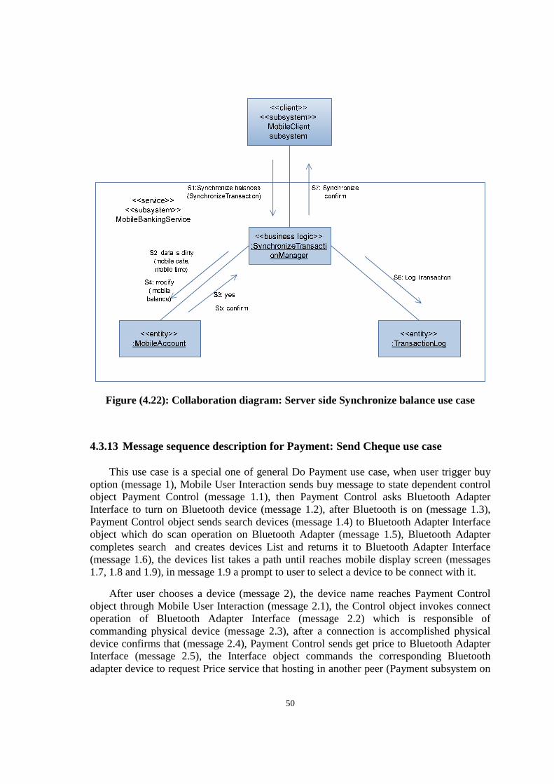
50
Figure (4.22): Collaboration diagram: Server side Synchronize balance use case
4.3.13 Message sequence description for Payment: Send Cheque use case
This use case is a special one of general Do Payment use case, when user trigger buy option (message 1), Mobile User Interaction sends buy message to state dependent control object Payment Control (message 1.1), then Payment Control asks Bluetooth Adapter Interface to turn on Bluetooth device (message 1.2), after Bluetooth is on (message 1.3), Payment Control object sends search devices (message 1.4) to Bluetooth Adapter Interface object which do scan operation on Bluetooth Adapter (message 1.5), Bluetooth Adapter completes search and creates devices List and returns it to Bluetooth Adapter Interface (message 1.6), the devices list takes a path until reaches mobile display screen (messages 1.7, 1.8 and 1.9), in message 1.9 a prompt to user to select a device to be connect with it.
After user chooses a device (message 2), the device name reaches Payment Control object through Mobile User Interaction (message 2.1), the Control object invokes connect operation of Bluetooth Adapter Interface (message 2.2) which is responsible of commanding physical device (message 2.3), after a connection is accomplished physical device confirms that (message 2.4), Payment Control sends get price to Bluetooth Adapter Interface (message 2.5), the Interface object commands the corresponding Bluetooth adapter device to request Price service that hosting in another peer (Payment subsystem on
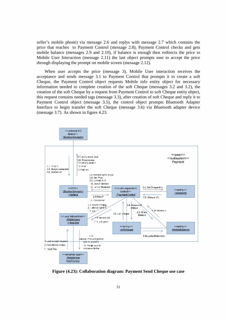
51
seller’s mobile phone) via message 2.6 and replys with message 2.7 which contains the price that reaches to Payment Control (message 2.8), Payment Control checks and gets mobile balance (messages 2.9 and 2.10), if balance is enough then redirects the price to Mobile User Interaction (message 2.11) the last object prompts user to accept the price through displaying the prompt on mobile screen (message 2.12).
When user accepts the price (message 3), Mobile User interaction receives the acceptance and sends message 3.1 to Payment Control that prompts it to create a soft Cheque, the Payment Control object requests Mobile info entity object for necessary information needed to complete creation of the soft Cheque (messages 3.2 and 3.2), the creation of the soft Cheque by a request from Payment Control to soft Cheque entity object, this request contains needed tags (message 3.3), after creation of soft Cheque and reply it to Payment Control object (message 3.5), the control object prompts Bluetooth Adapter Interface to begin transfer the soft Cheque (message 3.6) via Bluetooth adapter device (message 3.7). As shown in figure 4.23.
Figure (4.23): Collaboration diagram: Payment Send Cheque use case
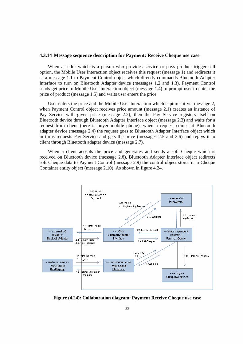
52
4.3.14 Message sequence description for Payment: Receive Cheque use case
When a seller which is a person who provides service or pays product trigger sell option, the Mobile User Interaction object receives this request (message 1) and redirects it as a message 1.1 to Payment Control object which directly commands Bluetooth Adapter Interface to turn on Bluetooth Adapter device (messages 1.2 and 1.3), Payment Control sends get price to Mobile User Interaction object (message 1.4) to prompt user to enter the price of product (message 1.5) and waits user enters the price.
User enters the price and the Mobile User Interaction which captures it via message 2, when Payment Control object receives price amount (message 2.1) creates an instance of Pay Service with given price (message 2.2), then the Pay Service registers itself on Bluetooth device through Bluetooth Adapter Interface object (message 2.3) and waits for a request from client (here is buyer mobile phone), when a request comes at Bluetooth adapter device (message 2.4) the request goes to Bluetooth Adapter Interface object which in turns requests Pay Service and gets the price (messages 2.5 and 2.6) and replys it to client through Bluetooth adapter device (message 2.7).
When a client accepts the price and generates and sends a soft Cheque which is received on Bluetooth device (message 2.8), Bluetooth Adapter Interface object redirects soft Cheque data to Payment Control (message 2.9) the control object stores it in Cheque Container entity object (message 2.10). As shown in figure 4.24.
Figure (4.24): Collaboration diagram: Payment Receive Cheque use case
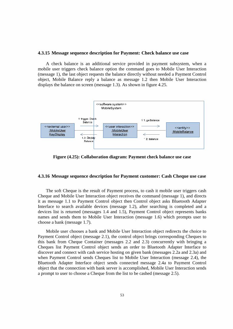
53
4.3.15 Message sequence description for Payment: Check balance use case
A check balance is an additional service provided in payment subsystem, when a mobile user triggers check balance option the command goes to Mobile User Interaction (message 1), the last object requests the balance directly without needed a Payment Control object, Mobile Balance reply a balance as message 1.2 then Mobile User Interaction displays the balance on screen (message 1.3). As shown in figure 4.25.
Figure (4.25): Collaboration diagram: Payment check balance use case
4.3.16 Message sequence description for Payment customer: Cash Cheque use case
The soft Cheque is the result of Payment process, to cash it mobile user triggers cash Cheque and Mobile User Interaction object receives the command (message 1), and directs it as message 1.1 to Payment Control object then Control object asks Bluetooth Adapter Interface to search available devices (message 1.2), after searching is completed and a devices list is returned (messages 1.4 and 1.5), Payment Control object represents banks names and sends them to Mobile User Interaction (message 1.6) which prompts user to choose a bank (message 1.7).
Mobile user chooses a bank and Mobile User Interaction object redirects the choice to Payment Control object (message 2.1), the control object brings corresponding Cheques to this bank from Cheque Container (messages 2.2 and 2.3) concurrently with bringing a Cheques list Payment Control object sends an order to Bluetooth Adapter Interface to discover and connect with cash service hosting on given bank (messages 2.2a and 2.3a) and when Payment Control sends Cheques list to Mobile User Interaction (message 2.4), the Bluetooth Adapter Interface object sends connected message 2.4a to Payment Control object that the connection with bank server is accomplished, Mobile User Interaction sends a prompt to user to choose a Cheque from the list to be cashed (message 2.5).
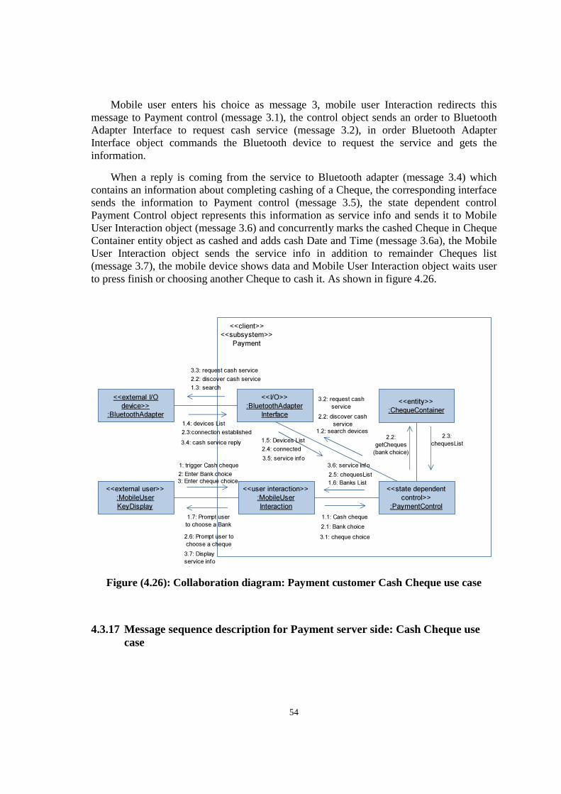
54
Mobile user enters his choice as message 3, mobile user Interaction redirects this message to Payment control (message 3.1), the control object sends an order to Bluetooth Adapter Interface to request cash service (message 3.2), in order Bluetooth Adapter Interface object commands the Bluetooth device to request the service and gets the information.
When a reply is coming from the service to Bluetooth adapter (message 3.4) which contains an information about completing cashing of a Cheque, the corresponding interface sends the information to Payment control (message 3.5), the state dependent control Payment Control object represents this information as service info and sends it to Mobile User Interaction object (message 3.6) and concurrently marks the cashed Cheque in Cheque Container entity object as cashed and adds cash Date and Time (message 3.6a), the Mobile User Interaction object sends the service info in addition to remainder Cheques list (message 3.7), the mobile device shows data and Mobile User Interaction object waits user to press finish or choosing another Cheque to cash it. As shown in figure 4.26.
Figure (4.26): Collaboration diagram: Payment customer Cash Cheque use case
4.3.17 Message sequence description for Payment server side: Cash Cheque use case
<<user interaction>>
:MobileUser
Interaction
<<state dependent
control>>
:PaymentControl
<<client>>
<<subsystem>>
Payment
<<entity>>
:ChequeContainer
<<external user>>
:MobileUser
KeyDisplay
1.6: Banks List
1: trigger Cash cheque
1.1: Cash cheque
2.5: chequesList2: Enter Bank choice
2.1: Bank choice
1.7: Prompt user
to choose a Bank
2.2:
getCheques
(bank choice)
2.3:
chequesList
2.6: Prompt user to
choose a cheque
3: Enter cheque choice
3.1: cheque choice
<<I/O>>
:BluetoothAdapter
Interface
<<external I/O
device>>
:BluetoothAdapter
1.2: search devices
2.2: discover cash
service
1.3: search
1.4: devices List
2.2: discover cash service
2.3:connection established
1.5: Devices List
3.2: request cash
service
3.3: request cash service
2.4: connected3.4: cash service reply
3.5: service info3.6: service info
3.7: Display
service info
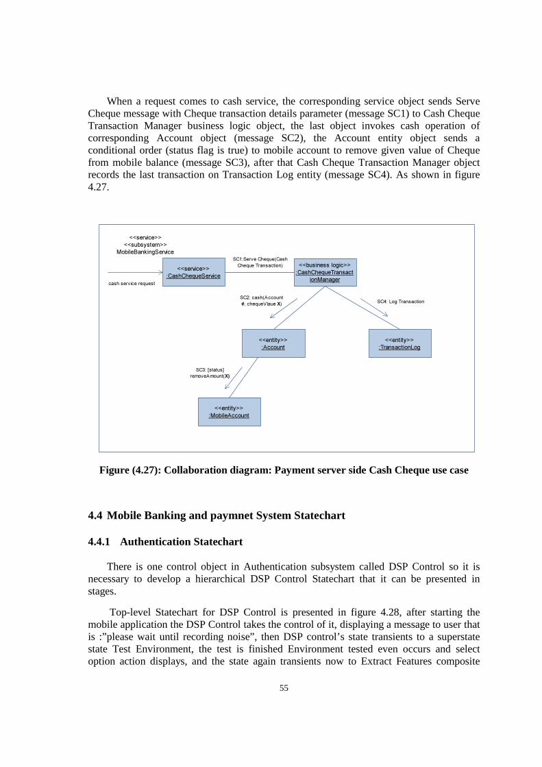
55
When a request comes to cash service, the corresponding service object sends Serve Cheque message with Cheque transaction details parameter (message SC1) to Cash Cheque Transaction Manager business logic object, the last object invokes cash operation of corresponding Account object (message SC2), the Account entity object sends a conditional order (status flag is true) to mobile account to remove given value of Cheque from mobile balance (message SC3), after that Cash Cheque Transaction Manager object records the last transaction on Transaction Log entity (message SC4). As shown in figure 4.27.
Figure (4.27): Collaboration diagram: Payment server side Cash Cheque use case
4.4 Mobile Banking and paymnet System Statechart
4.4.1 Authentication Statechart
There is one control object in Authentication subsystem called DSP Control so it is necessary to develop a hierarchical DSP Control Statechart that it can be presented in stages.
Top-level Statechart for DSP Control is presented in figure 4.28, after starting the mobile application the DSP Control takes the control of it, displaying a message to user that is :”please wait until recording noise”, then DSP control’s state transients to a superstate state Test Environment, the test is finished Environment tested even occurs and select option action displays, and the state again transients now to Extract Features composite
<<business logic>>
:CashChequeTransact
ionManager
<<entity>>
:Account
<<entity>>
:TransactionLog
<<service>>
<<subsystem>>
MobileBankingServiceSC1:Serve Cheque(Cash
Cheque Transaction)
SC2: cash(Account
#, chequeVlaue X)SC4: Log Transaction
<<entity>>
:MobileAccount
SC3: [status]
removeAmount(X)
<<service>>
:CashChequeService
cash service request
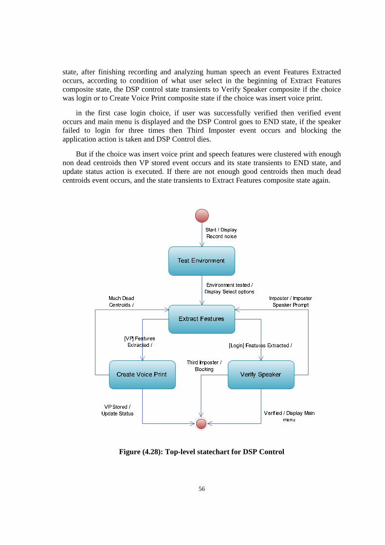
56
state, after finishing recording and analyzing human speech an event Features Extracted occurs, according to condition of what user select in the beginning of Extract Features composite state, the DSP control state transients to Verify Speaker composite if the choice was login or to Create Voice Print composite state if the choice was insert voice print.
in the first case login choice, if user was successfully verified then verified event occurs and main menu is displayed and the DSP Control goes to END state, if the speaker failed to login for three times then Third Imposter event occurs and blocking the application action is taken and DSP Control dies.
But if the choice was insert voice print and speech features were clustered with enough non dead centroids then VP stored event occurs and its state transients to END state, and update status action is executed. If there are not enough good centroids then much dead centroids event occurs, and the state transients to Extract Features composite state again.
Figure (4.28): Top-level statechart for DSP Control
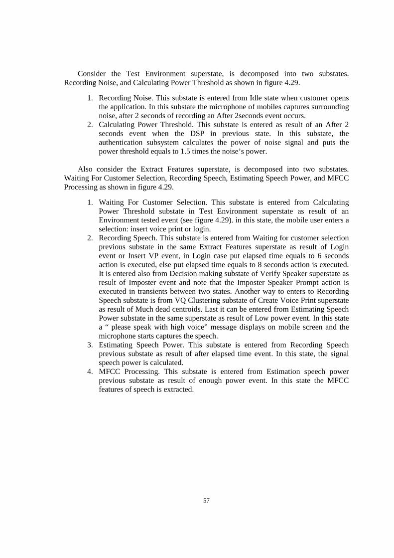
57
Consider the Test Environment superstate, is decomposed into two substates. Recording Noise, and Calculating Power Threshold as shown in figure 4.29.
1. Recording Noise. This substate is entered from Idle state when customer opens the application. In this substate the microphone of mobiles captures surrounding noise, after 2 seconds of recording an After 2seconds event occurs.
2. Calculating Power Threshold. This substate is entered as result of an After 2 seconds event when the DSP in previous state. In this substate, the authentication subsystem calculates the power of noise signal and puts the power threshold equals to 1.5 times the noise’s power.
Also consider the Extract Features superstate, is decomposed into two substates. Waiting For Customer Selection, Recording Speech, Estimating Speech Power, and MFCC Processing as shown in figure 4.29.
1. Waiting For Customer Selection. This substate is entered from Calculating Power Threshold substate in Test Environment superstate as result of an Environment tested event (see figure 4.29). in this state, the mobile user enters a selection: insert voice print or login.
2. Recording Speech. This substate is entered from Waiting for customer selection previous substate in the same Extract Features superstate as result of Login event or Insert VP event, in Login case put elapsed time equals to 6 seconds action is executed, else put elapsed time equals to 8 seconds action is executed. It is entered also from Decision making substate of Verify Speaker superstate as result of Imposter event and note that the Imposter Speaker Prompt action is executed in transients between two states. Another way to enters to Recording Speech substate is from VQ Clustering substate of Create Voice Print superstate as result of Much dead centroids. Last it can be entered from Estimating Speech Power substate in the same superstate as result of Low power event. In this state a “ please speak with high voice” message displays on mobile screen and the microphone starts captures the speech.
3. Estimating Speech Power. This substate is entered from Recording Speech previous substate as result of after elapsed time event. In this state, the signal speech power is calculated.
4. MFCC Processing. This substate is entered from Estimation speech power previous substate as result of enough power event. In this state the MFCC features of speech is extracted.

58
Figure (4.29): Statechart for DSP control: Test environment & Extract features composite states
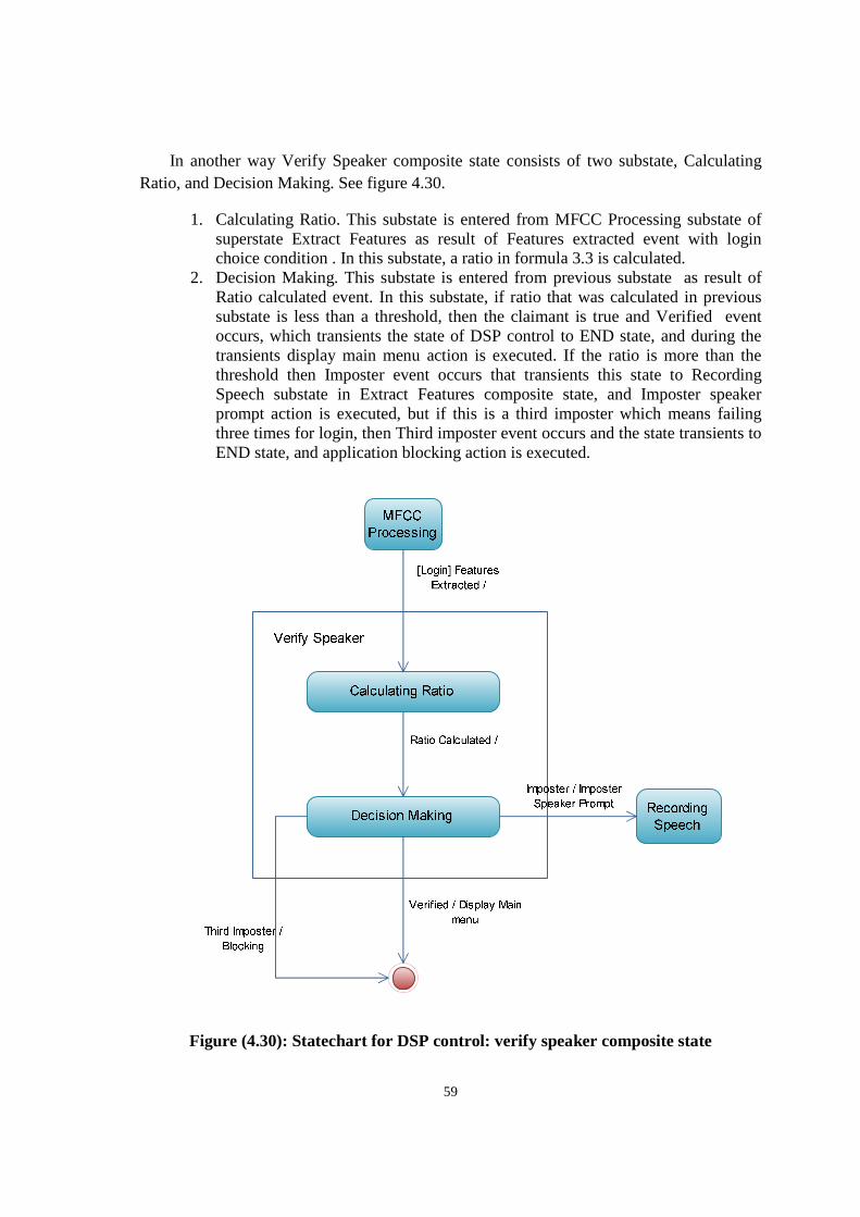
59
In another way Verify Speaker composite state consists of two substate, Calculating Ratio, and Decision Making. See figure 4.30.
1. Calculating Ratio. This substate is entered from MFCC Processing substate of superstate Extract Features as result of Features extracted event with login choice condition . In this substate, a ratio in formula 3.3 is calculated.
2. Decision Making. This substate is entered from previous substate as result of Ratio calculated event. In this substate, if ratio that was calculated in previous substate is less than a threshold, then the claimant is true and Verified event occurs, which transients the state of DSP control to END state, and during the transients display main menu action is executed. If the ratio is more than the threshold then Imposter event occurs that transients this state to Recording Speech substate in Extract Features composite state, and Imposter speaker prompt action is executed, but if this is a third imposter which means failing three times for login, then Third imposter event occurs and the state transients to END state, and application blocking action is executed.
Figure (4.30): Statechart for DSP control: verify speaker composite state
60
The last composite state in DSP Control top-level statechart is Create Voice Print, which consists of VQ clustering substate, and Storing Voice Print substate. See figure 4.31
1. Create Voice Print. This substate is entered from MFCC Processing substate of Extract features superstate as result of Features extracted event with insert voice print choice condition. In this substate the extracted features are clustered using VQ and LBG.
2. Storing Voice Print. This substate is entered from previous VQ Clustering substate as result of Enough good centroids event. In this substate the voice print is stored on a file. Storing voice print substate transients to END state as result of VP stored event and update status action is executed.
Figure (4.31): Statechart for DSP control: create voice print composite state
4.4.2 Mobile client statechart
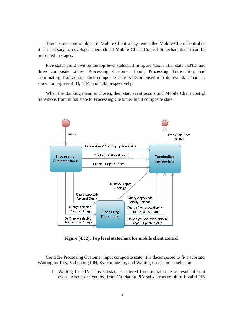
61
There is one control object in Mobile Client subsystem called Mobile Client Control so it is necessary to develop a hierarchical Mobile Client Control Statechart that it can be presented in stages.
Five states are shown on the top-level statechart in figure 4.32: initial state , END, and three composite states, Processing Customer Input, Processing Transaction, and Terminating Transaction. Each composite state is decomposed into its own statechart, as shown on Figures 4.33, 4.34, and 4.35, respectively.
When the Banking menu is chosen, then start event occurs and Mobile Client control transitions from initial state to Processing Customer Input composite state.
Figure (4.32): Top level statechart for mobile client control
Consider Processing Customer Input composite state, it is decomposed to five substate: Waiting for PIN, Validating PIN, Synchronizing, and Waiting for customer selection.
1. Waiting for PIN. This substate is entered from initial state as result of start event. Also it can entered from Validating PIN substate as result of Invalid PIN
62
event, and Invalid PIN prompt action is executed In this state, the Mobile client control waits for the customer to enter the PIN.
2. Validating PIN. This substate is entered from previous substate when user enters the PIN. In this substate, the Banking Service validates the PIN.
3. Synchronizing. This substate is entered from previous substate as result of a Valid PIN event. In this substate bank server synchronizes its mobile account balance with this mobile balance.
4. Waiting For Customer Selection. This substate is entered from previous substate as result of a Synchronize complete event, and display bank menu action is executed. In this state, the customer enters the selection: Query Account, Charge or Discharge mobile.
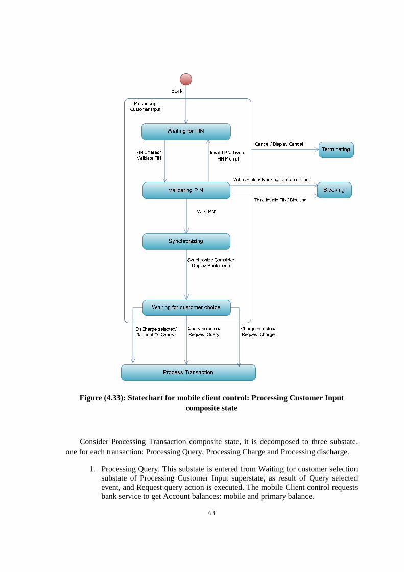
63
Figure (4.33): Statechart for mobile client control: Processing Customer Input composite state
Consider Processing Transaction composite state, it is decomposed to three substate, one for each transaction: Processing Query, Processing Charge and Processing discharge.
1. Processing Query. This substate is entered from Waiting for customer selection substate of Processing Customer Input superstate, as result of Query selected event, and Request query action is executed. The mobile Client control requests bank service to get Account balances: mobile and primary balance.
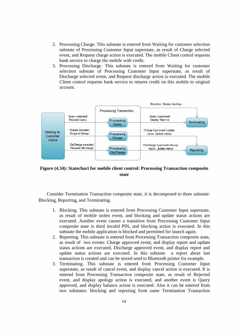
64
2. Processing Charge. This substate is entered from Waiting for customer selection substate of Processing Customer Input superstate, as result of Charge selected event, and Request charge action is executed. The mobile Client control requests bank service to charge the mobile with credit.
3. Processing Discharge. This substate is entered from Waiting for customer selection substate of Processing Customer Input superstate, as result of Discharge selected event, and Request discharge action is executed. The mobile Client control requests bank service to returns credit on this mobile to original account.
Figure (4.34): Statechart for mobile client control: Processing Transaction composite state
Consider Termination Transaction composite state, it is decomposed to three substate: Blocking, Reporting, and Terminating.
1. Blocking. This substate is entered from Processing Customer Input superstate, as result of mobile stolen event, and blocking and update status actions are executed. Another event causes a transition from Processing Customer Input composite state is third invalid PIN, and blocking action is executed. In this substate the mobile application is blocked and permitted for launch again.
2. Reporting. This substate is entered from Processing Transaction composite state, as result of two events: Charge approved event, and display report and update status actions are executed, Discharge approved event, and display report and update status actions are executed. In this substate a report about last transaction is created and can be stored send to Bluetooth printer for example.
3. Terminating. This substate is entered from Processing Customer Input superstate, as result of cancel event, and display cancel action is executed. It is entered from Processing Transaction composite state, as result of Rejected event, and display apology action is executed, and another event is Query approved, and display balance action is executed. Also it can be entered from two substates: blocking and reporting from same Termination Transaction
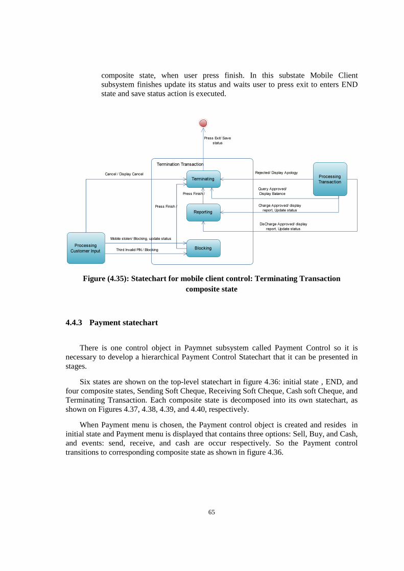
65
composite state, when user press finish. In this substate Mobile Client subsystem finishes update its status and waits user to press exit to enters END state and save status action is executed.
Figure (4.35): Statechart for mobile client control: Terminating Transaction composite state
4.4.3 Payment statechart
There is one control object in Paymnet subsystem called Payment Control so it is necessary to develop a hierarchical Payment Control Statechart that it can be presented in stages.
Six states are shown on the top-level statechart in figure 4.36: initial state , END, and four composite states, Sending Soft Cheque, Receiving Soft Cheque, Cash soft Cheque, and Terminating Transaction. Each composite state is decomposed into its own statechart, as shown on Figures 4.37, 4.38, 4.39, and 4.40, respectively.
When Payment menu is chosen, the Payment control object is created and resides in initial state and Payment menu is displayed that contains three options: Sell, Buy, and Cash, and events: send, receive, and cash are occur respectively. So the Payment control transitions to corresponding composite state as shown in figure 4.36.
Termination Transaction
Terminating
Blocking
Reporting
Processing
Customer Input
Mobile stolen/ Blocking, update status
Third Invalid PIN / Blocking
Cancel / Display CancelProcessing
Transaction
Rejected/ Display Apology
Query Approved/
Display Balance
Charge Approved/ display
report, Update status
DisCharge Approved/ display
report, Update status
Press Exit/ Save
status
Press Finish /
Press Finish /
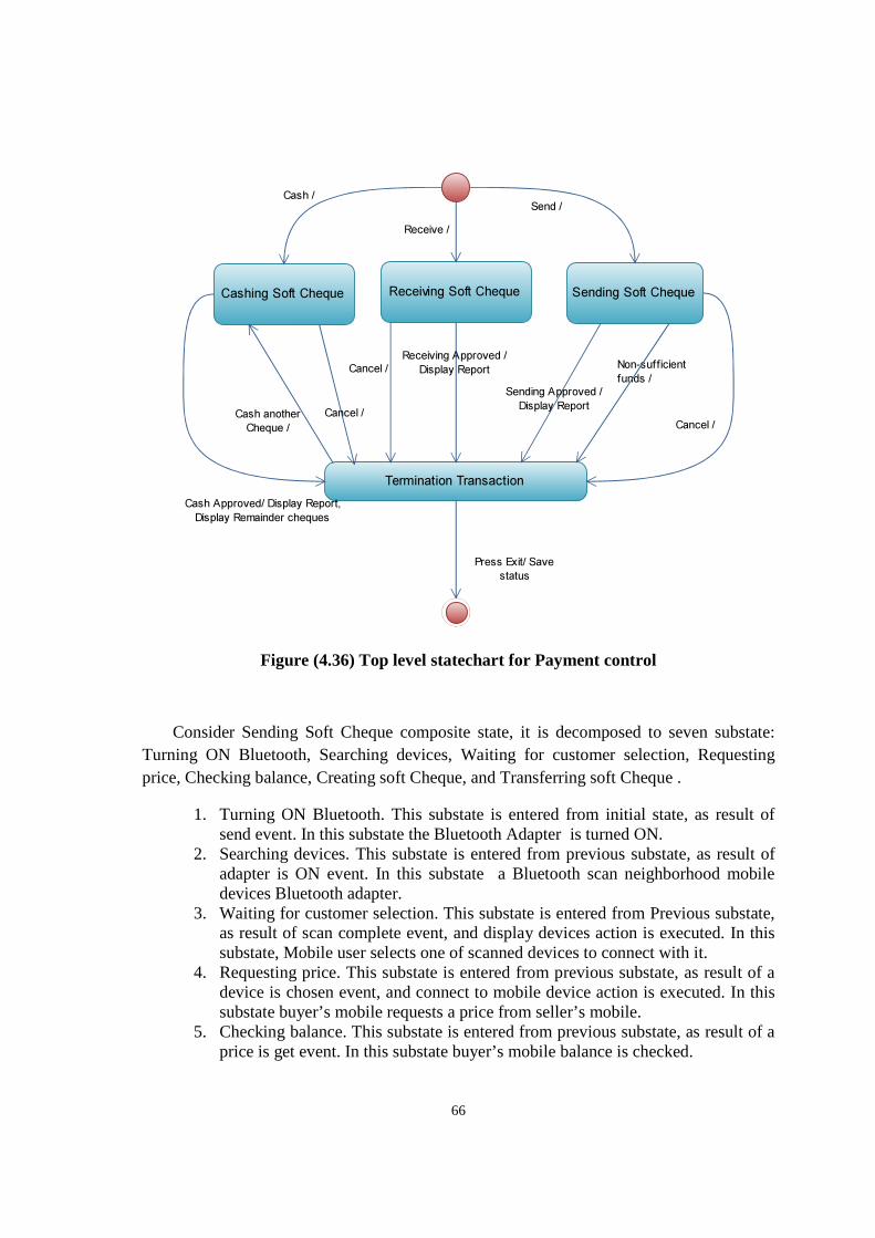
66
Figure (4.36) Top level statechart for Payment control
Consider Sending Soft Cheque composite state, it is decomposed to seven substate: Turning ON Bluetooth, Searching devices, Waiting for customer selection, Requesting price, Checking balance, Creating soft Cheque, and Transferring soft Cheque .
1. Turning ON Bluetooth. This substate is entered from initial state, as result of send event. In this substate the Bluetooth Adapter is turned ON.
2. Searching devices. This substate is entered from previous substate, as result of adapter is ON event. In this substate a Bluetooth scan neighborhood mobile devices Bluetooth adapter.
3. Waiting for customer selection. This substate is entered from Previous substate, as result of scan complete event, and display devices action is executed. In this substate, Mobile user selects one of scanned devices to connect with it.
4. Requesting price. This substate is entered from previous substate, as result of a device is chosen event, and connect to mobile device action is executed. In this substate buyer’s mobile requests a price from seller’s mobile.
5. Checking balance. This substate is entered from previous substate, as result of a price is get event. In this substate buyer’s mobile balance is checked.
Cashing Soft Cheque Receiving Soft Cheque Sending Soft Cheque
Termination Transaction
Cash /
Receive /
Send /
Cancel /
Cancel / Non-sufficient
funds /
Press Exit/ Save
status
Cash another
Cheque /
Sending Approved /
Display Report
Receiving Approved /
Display Report
Cash Approved/ Display Report,
Display Remainder cheques
Cancel /
67
6. Creating soft Cheque. This substate is entered from previous substate, as result of a sufficient funds event, and get Cheque data action is executed. In this substate, a soft Cheque is created.
7. Transferring soft Cheque. This substate is entered from previous substate, as result of a Cheque created event. In this substate, the buyer’s mobile sends a soft Cheque to seller’s mobile.
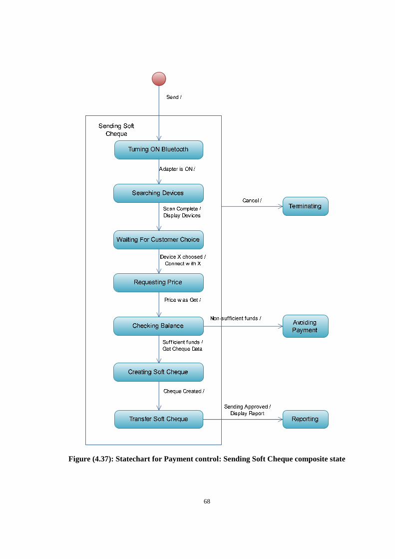
68
Figure (4.37): Statechart for Payment control: Sending Soft Cheque composite state
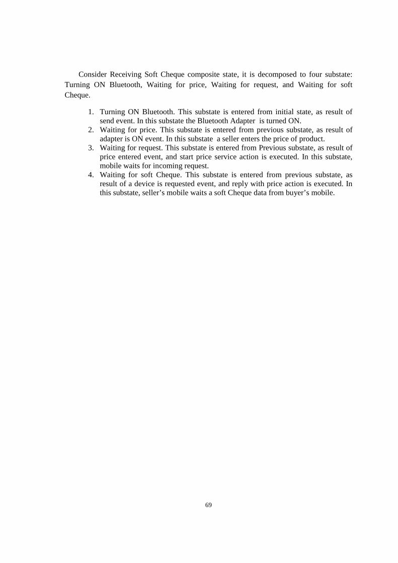
69
Consider Receiving Soft Cheque composite state, it is decomposed to four substate: Turning ON Bluetooth, Waiting for price, Waiting for request, and Waiting for soft Cheque.
1. Turning ON Bluetooth. This substate is entered from initial state, as result of send event. In this substate the Bluetooth Adapter is turned ON.
2. Waiting for price. This substate is entered from previous substate, as result of adapter is ON event. In this substate a seller enters the price of product.
3. Waiting for request. This substate is entered from Previous substate, as result of price entered event, and start price service action is executed. In this substate, mobile waits for incoming request.
4. Waiting for soft Cheque. This substate is entered from previous substate, as result of a device is requested event, and reply with price action is executed. In this substate, seller’s mobile waits a soft Cheque data from buyer’s mobile.
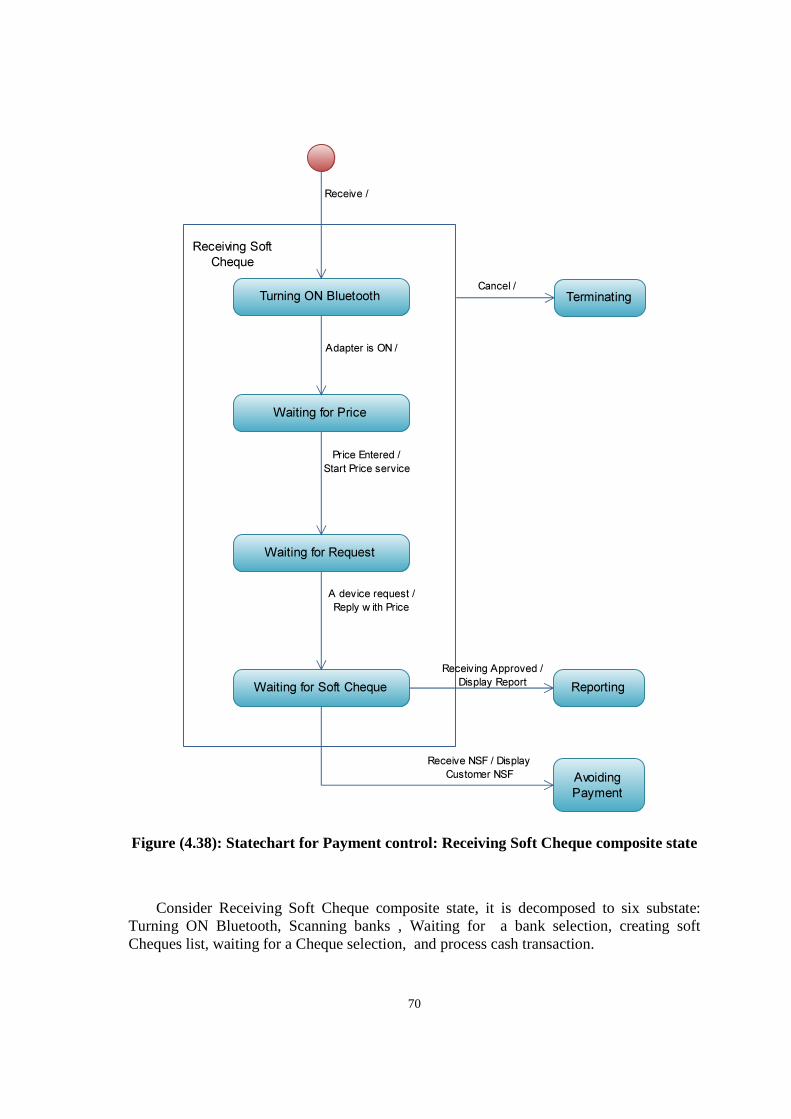
70
Figure (4.38): Statechart for Payment control: Receiving Soft Cheque composite state
Consider Receiving Soft Cheque composite state, it is decomposed to six substate: Turning ON Bluetooth, Scanning banks , Waiting for a bank selection, creating soft Cheques list, waiting for a Cheque selection, and process cash transaction.
Receiving Soft
Cheque
Turning ON Bluetooth
Waiting for Price
Waiting for Request
Waiting for Soft Cheque
Adapter is ON /
Price Entered /
Start Price service
A device request /
Reply w ith Price
Terminating
Reporting
Avoiding
Payment
Receiving Approved /
Display Report
Receive /
Cancel /
Receive NSF / Display
Customer NSF
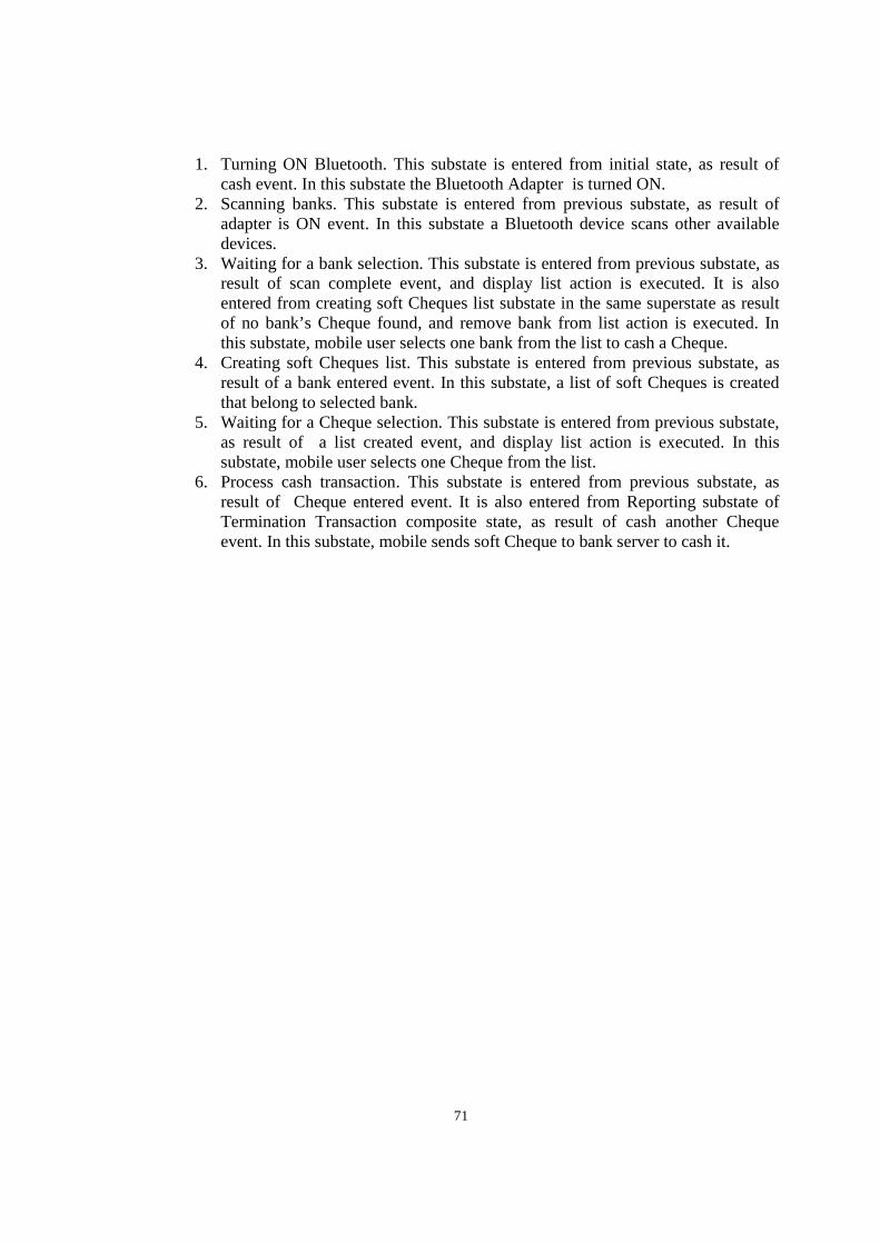
71
1. Turning ON Bluetooth. This substate is entered from initial state, as result of cash event. In this substate the Bluetooth Adapter is turned ON.
2. Scanning banks. This substate is entered from previous substate, as result of adapter is ON event. In this substate a Bluetooth device scans other available devices.
3. Waiting for a bank selection. This substate is entered from previous substate, as result of scan complete event, and display list action is executed. It is also entered from creating soft Cheques list substate in the same superstate as result of no bank’s Cheque found, and remove bank from list action is executed. In this substate, mobile user selects one bank from the list to cash a Cheque.
4. Creating soft Cheques list. This substate is entered from previous substate, as result of a bank entered event. In this substate, a list of soft Cheques is created that belong to selected bank.
5. Waiting for a Cheque selection. This substate is entered from previous substate, as result of a list created event, and display list action is executed. In this substate, mobile user selects one Cheque from the list.
6. Process cash transaction. This substate is entered from previous substate, as result of Cheque entered event. It is also entered from Reporting substate of Termination Transaction composite state, as result of cash another Cheque event. In this substate, mobile sends soft Cheque to bank server to cash it.
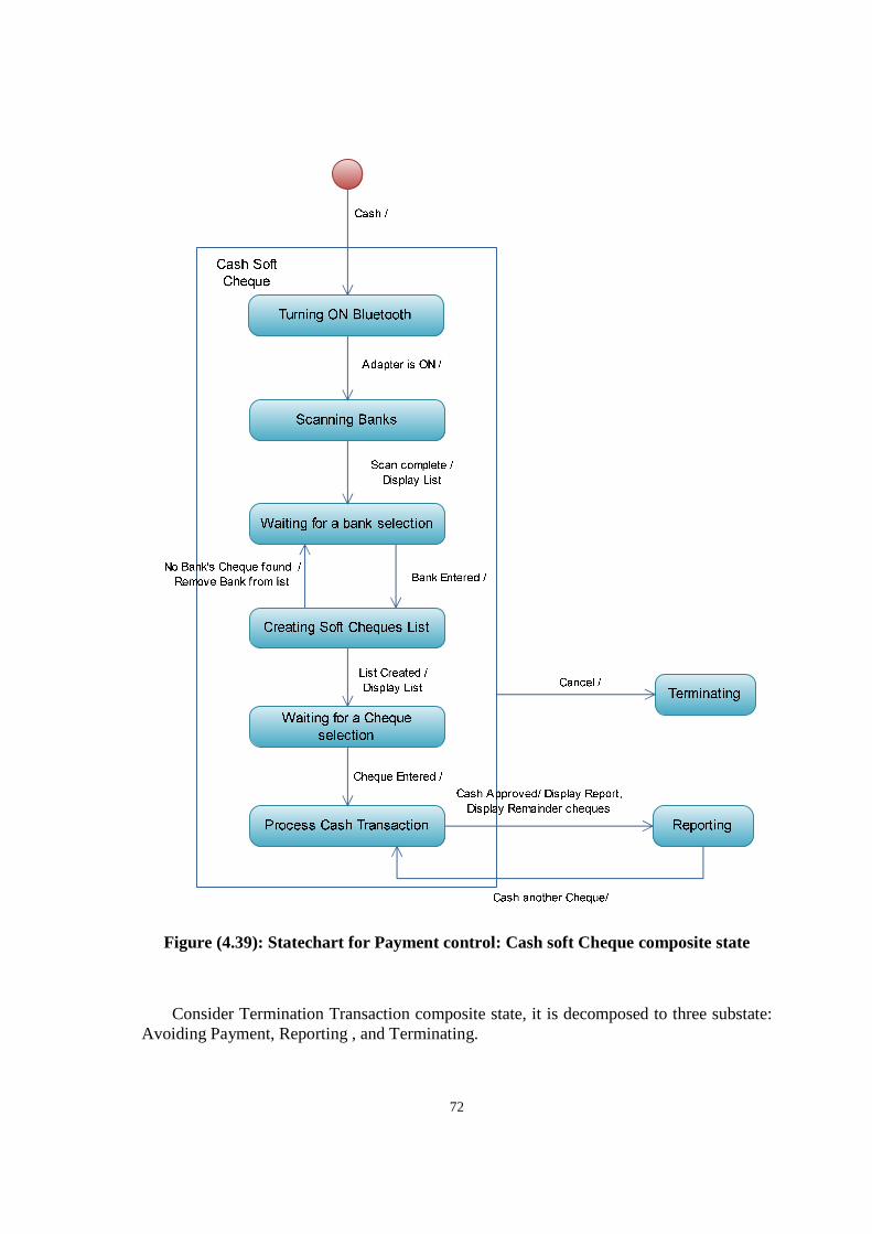
72
Figure (4.39): Statechart for Payment control: Cash soft Cheque composite state
Consider Termination Transaction composite state, it is decomposed to three substate: Avoiding Payment, Reporting , and Terminating.
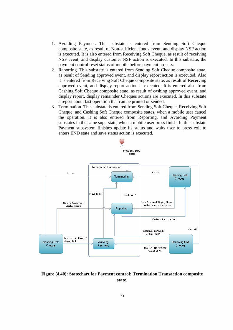
73
1. Avoiding Payment. This substate is entered from Sending Soft Cheque composite state, as result of Non-sufficient funds event, and display NSF action is executed. It is also entered from Receiving Soft Cheque, as result of receiving NSF event, and display customer NSF action is executed. In this substate, the payment control reset status of mobile before payment process.
2. Reporting. This substate is entered from Sending Soft Cheque composite state, as result of Sending approved event, and display report action is executed. Also it is entered from Receiving Soft Cheque composite state, as result of Receiving approved event, and display report action is executed. It is entered also from Cashing Soft Cheque composite state, as result of cashing approved event, and display report, display remainder Cheques actions are executed. In this substate a report about last operation that can be printed or sended.
3. Termination. This substate is entered from Sending Soft Cheque, Receiving Soft Cheque, and Cashing Soft Cheque composite states, when a mobile user cancel the operation. It is also entered from Reporting, and Avoiding Payment substates in the same superstate, when a mobile user press finish. In this substate Payment subsystem finishes update its status and waits user to press exit to enters END state and save status action is executed.
Figure (4.40): Statechart for Payment control: Termination Transaction composite state.
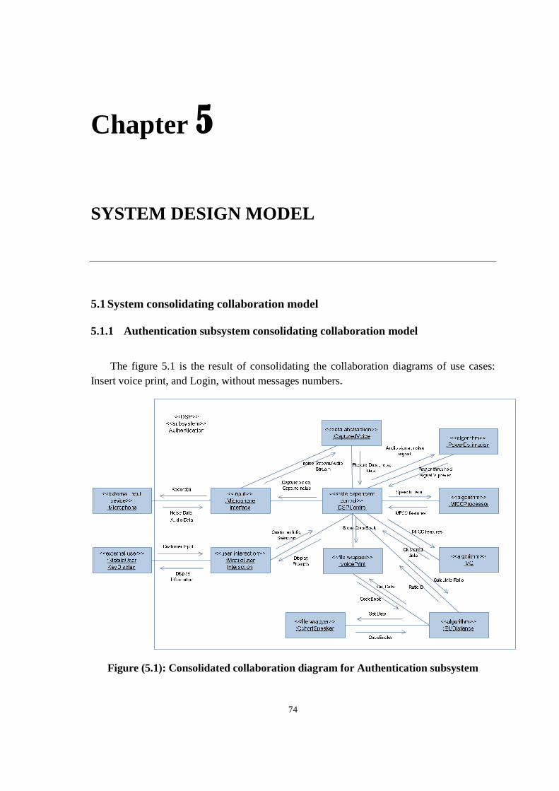
74
Chapter 5
SYSTEM DESIGN MODEL
5.1 System consolidating collaboration model
5.1.1 Authentication subsystem consolidating collaboration model
The figure 5.1 is the result of consolidating the collaboration diagrams of use cases: Insert voice print, and Login, without messages numbers.
Figure (5.1): Consolidated collaboration diagram for Authentication subsystem
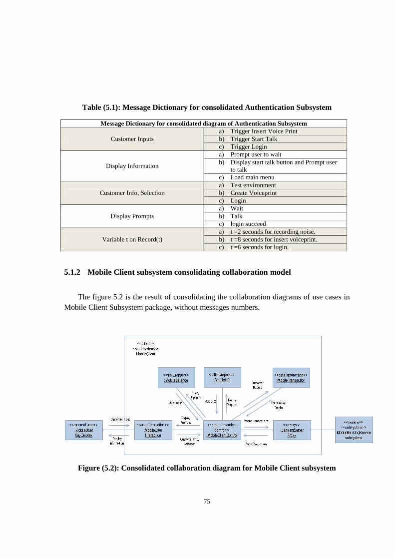
75
Table (5.1): Message Dictionary for consolidated Authentication Subsystem
Message Dictionary for consolidated diagram of Authentication Subsystem
Customer Inputs a) Trigger Insert Voice Print b) Trigger Start Talk c) Trigger Login
Display Information
a) Prompt user to wait b) Display start talk button and Prompt user
to talk c) Load main menu
Customer Info, Selection a) Test environment b) Create Voiceprint c) Login
Display Prompts a) Wait b) Talk c) login succeed
Variable t on Record(t) a) t =2 seconds for recording noise. b) t =8 seconds for insert voiceprint. c) t =6 seconds for login.
5.1.2 Mobile Client subsystem consolidating collaboration model
The figure 5.2 is the result of consolidating the collaboration diagrams of use cases in Mobile Client Subsystem package, without messages numbers.
Figure (5.2): Consolidated collaboration diagram for Mobile Client subsystem
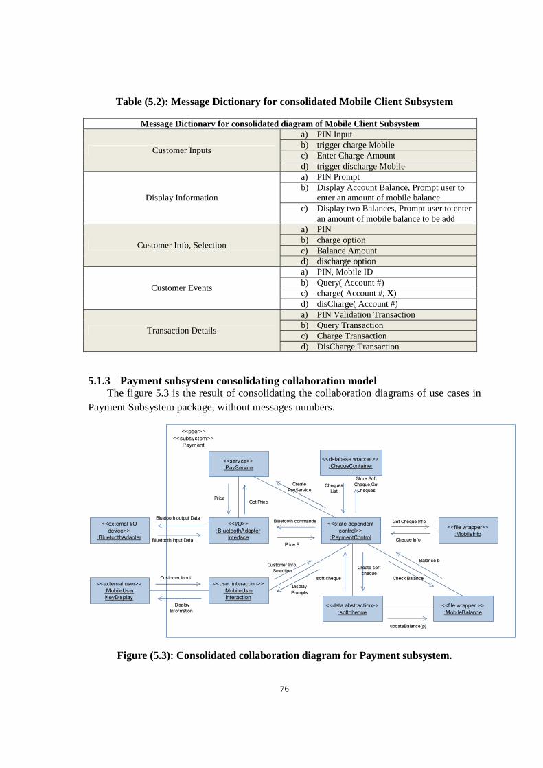
76
Table (5.2): Message Dictionary for consolidated Mobile Client Subsystem
Message Dictionary for consolidated diagram of Mobile Client Subsystem
Customer Inputs
a) PIN Input b) trigger charge Mobile c) Enter Charge Amount d) trigger discharge Mobile
Display Information
a) PIN Prompt b) Display Account Balance, Prompt user to
enter an amount of mobile balance c) Display two Balances, Prompt user to enter
an amount of mobile balance to be add
Customer Info, Selection
a) PIN b) charge option c) Balance Amount d) discharge option
Customer Events
a) PIN, Mobile ID b) Query( Account #) c) charge( Account #, X) d) disCharge( Account #)
Transaction Details
a) PIN Validation Transaction b) Query Transaction c) Charge Transaction d) DisCharge Transaction
5.1.3 Payment subsystem consolidating collaboration model The figure 5.3 is the result of consolidating the collaboration diagrams of use cases in Payment Subsystem package, without messages numbers.
Figure (5.3): Consolidated collaboration diagram for Payment subsystem.
<<external user>>
:MobileUser
KeyDisplay
<<user interaction>>
:MobileUser
Interaction
<<I/O>>
:BluetoothAdapter
Interface
<<external I/O
device>>
:BluetoothAdapter
<<file wrapper >>
:MobileBalance
<<state dependent
control>>
:PaymentControl
Bluetooth commands
Bluetooth Input Data
<<file wrapper>>
:MobileInfo
Balance b
Get Cheque Info
Cheque Info
<<peer>>
<<subsystem>>
Payment
Price P
Check Balance
<<data abstraction>>
:softcheque
Create soft
chequesoft cheque Customer Input
Display
Information
Customer Info,
Selection
Display
Prompts
updateBalance(p)
Bluetooth output Data
<<service>>
:PayService
Get PricePrice
Create
PayService
<<database wrapper>>
:ChequeContainer
Store Soft
Cheque,Get
Cheques Cheques
List
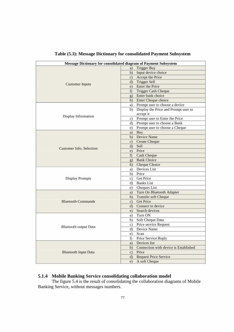
77
Table (5.3): Message Dictionary for consolidated Payment Subsystem
Message Dictionary for consolidated diagram of Payment Subsystem
Customer Inputs
a) Trigger Buy b) Input device choice c) Accept the Price d) Trigger Sell e) Enter the Price f) Trigger Cash Cheque g) Enter bank choice h) Enter Cheque choice
Display Information
a) Prompt user to choose a device b) Display the Price and Prompt user to
accept it c) Prompt user to Enter the Price d) Prompt user to choose a Bank e) Prompt user to choose a Cheque
Customer Info, Selection
a) Buy b) Device Name c) Create Cheque d) Sell e) Price f) Cash Cheque g) Bank Choice h) Cheque Choice
Display Prompts
a) Devices List b) Price c) Get Price d) Banks List e) Cheques List
Bluetooth Commands
a) Turn On Bluetooth Adapter b) Transfer soft Cheque c) Get Price d) Connect to device e) Search devices
Bluetooth output Data
a) Turn ON b) Soft Cheque Data c) Price service Request d) Device Name e) Scan f) Price Service Reply
Bluetooth Input Data
a) Devices list b) Connection with device is Established c) Price d) Request Price Service e) A soft Cheque
5.1.4 Mobile Banking Service consolidating collaboration model The figure 5.4 is the result of consolidating the collaboration diagrams of Mobile Banking Service, without messages numbers.
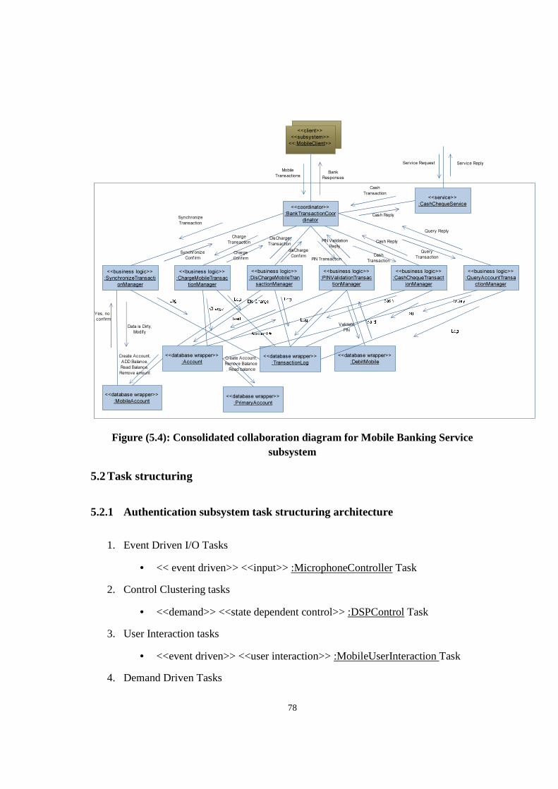
78
Figure (5.4): Consolidated collaboration diagram for Mobile Banking Service subsystem
5.2 Task structuring
5.2.1 Authentication subsystem task structuring architecture
1. Event Driven I/O Tasks
• << event driven>> <<input>> :MicrophoneController Task
2. Control Clustering tasks
• <<demand>> <<state dependent control>> :DSPControl Task
3. User Interaction tasks
• <<event driven>> <<user interaction>> :MobileUserInteraction Task
4. Demand Driven Tasks
<<client>>
<<subsystem>>
<<:MobileClient>>
<<coordinator>>
:BankTransactionCoor
dinator
<<business logic>>
:PINValidationTransac
tionManager
<<business logic>>
:DisChargeMobileTran
sactionManager
<<business logic>>
:ChargeMobileTransac
tionManager
<<business logic>>
:CashChequeTransact
ionManager
<<business logic>>
:QueryAccountTransa
ctionManager
<<business logic>>
:SynchronizeTransacti
onManager
Bank
Responses
Mobile
Transactions
Synchronize
Transaction
Synchronize
Confirm
Charge
Transaction
Charge
Confirm
DisCharge
Transaction
disCharge
ConfirmPIN Transaction
PIN Validation
Reply
Cash
Transaction
Cash Reply
Query
Transaction
Query Reply
<<database wrapper>>
:DebitMobile
<<database wrapper>>
:Account<<database wrapper>>
:TransactionLog
Validate
PIN
<<database wrapper>>
:MobileAccount
Create Account,
ADD Balance,
Read Balance,
Remove amount
<<database wrapper>>
:PrimaryAccount
Create Account,
Remove Balance
, Read balance
Data is Dirty,
Modify
Yes, no
, confirm
<<service>>
:CashChequeService
Cash
Transaction
Cash Reply
Service Request Service Reply
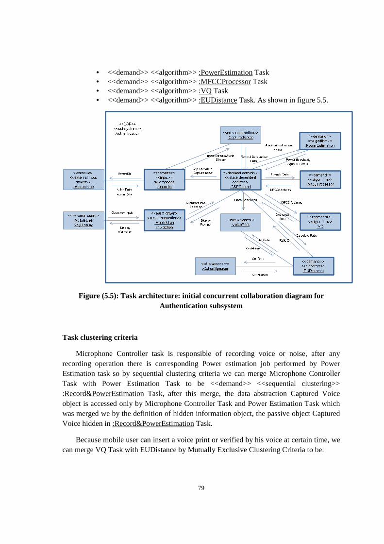
79
• <<demand>> <<algorithm>> :PowerEstimation Task • <<demand>> <<algorithm>> :MFCCProcessor Task • <<demand>> <<algorithm>> :VQ Task • <<demand>> <<algorithm>> :EUDistance Task. As shown in figure 5.5.
Figure (5.5): Task architecture: initial concurrent collaboration diagram for Authentication subsystem
Task clustering criteria
Microphone Controller task is responsible of recording voice or noise, after any recording operation there is corresponding Power estimation job performed by Power Estimation task so by sequential clustering criteria we can merge Microphone Controller Task with Power Estimation Task to be <<demand>> <<sequential clustering>> :Record&PowerEstimation Task, after this merge, the data abstraction Captured Voice object is accessed only by Microphone Controller Task and Power Estimation Task which was merged we by the definition of hidden information object, the passive object Captured Voice hidden in :Record&PowerEstimation Task.
Because mobile user can insert a voice print or verified by his voice at certain time, we can merge VQ Task with EUDistance by Mutually Exclusive Clustering Criteria to be:
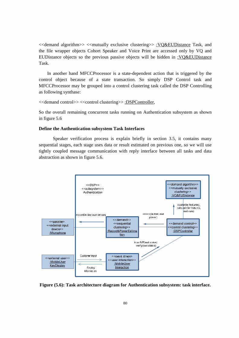
80
<<demand algorithm>> <<mutually exclusive clustering>> :VQ&EUDistance Task, and the file wrapper objects Cohort Speaker and Voice Print are accessed only by VQ and EUDistance objects so the previous passive objects will be hidden in :VQ&EUDistance Task.
In another hand MFCCProcessor is a state-dependent action that is triggered by the control object because of a state transaction. So simply DSP Control task and MFCCProcessor may be grouped into a control clustering task called the DSP Controlling as following synthase:
<<demand control>> <<control clustering>> :DSPController,
So the overall remaining concurrent tasks running on Authentication subsystem as shown in figure 5.6
Define the Authentication subsystem Task Interfaces
Speaker verification process is explain briefly in section 3.5, it contains many sequential stages, each stage uses data or result estimated on previous one, so we will use tightly coupled message communication with reply interface between all tasks and data abstraction as shown in figure 5.6.
Figure (5.6): Task architecture diagram for Authentication subsystem: task interface.
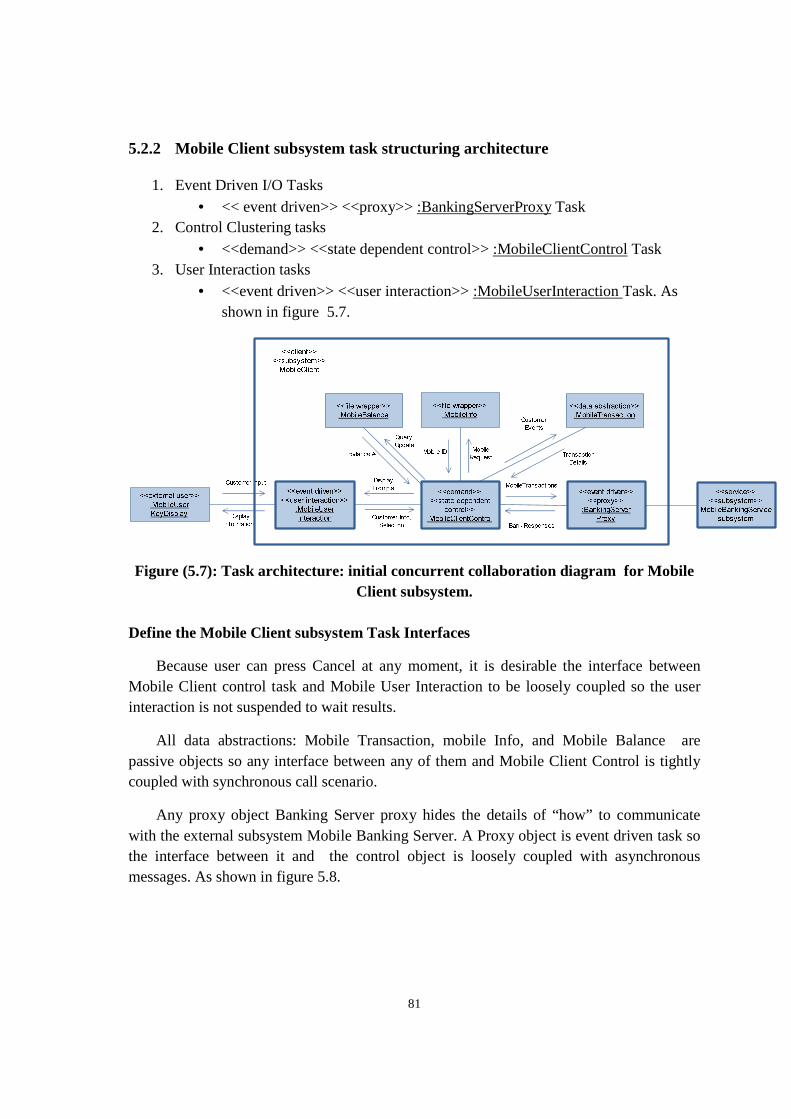
81
5.2.2 Mobile Client subsystem task structuring architecture
1. Event Driven I/O Tasks
• << event driven>> <<proxy>> :BankingServerProxy Task 2. Control Clustering tasks
• <<demand>> <<state dependent control>> :MobileClientControl Task 3. User Interaction tasks
• <<event driven>> <<user interaction>> :MobileUserInteraction Task. As shown in figure 5.7.
Figure (5.7): Task architecture: initial concurrent collaboration diagram for Mobile Client subsystem.
Define the Mobile Client subsystem Task Interfaces
Because user can press Cancel at any moment, it is desirable the interface between Mobile Client control task and Mobile User Interaction to be loosely coupled so the user interaction is not suspended to wait results.
All data abstractions: Mobile Transaction, mobile Info, and Mobile Balance are passive objects so any interface between any of them and Mobile Client Control is tightly coupled with synchronous call scenario.
Any proxy object Banking Server proxy hides the details of “how” to communicate with the external subsystem Mobile Banking Server. A Proxy object is event driven task so the interface between it and the control object is loosely coupled with asynchronous messages. As shown in figure 5.8.
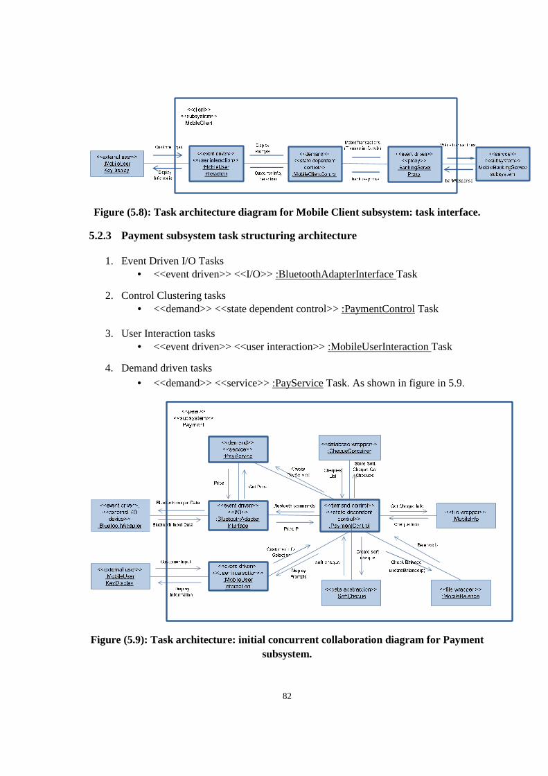
82
Figure (5.8): Task architecture diagram for Mobile Client subsystem: task interface.
5.2.3 Payment subsystem task structuring architecture
1. Event Driven I/O Tasks • <<event driven>> <<I/O>> :BluetoothAdapterInterface Task
2. Control Clustering tasks • <<demand>> <<state dependent control>> :PaymentControl Task
3. User Interaction tasks
• <<event driven>> <<user interaction>> :MobileUserInteraction Task
4. Demand driven tasks
• <<demand>> <<service>> :PayService Task. As shown in figure in 5.9.
Figure (5.9): Task architecture: initial concurrent collaboration diagram for Payment subsystem.
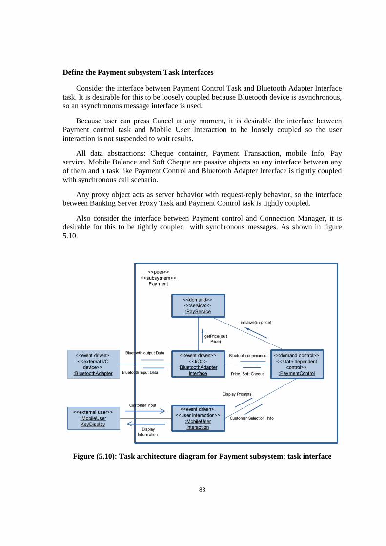
83
Define the Payment subsystem Task Interfaces
Consider the interface between Payment Control Task and Bluetooth Adapter Interface task. It is desirable for this to be loosely coupled because Bluetooth device is asynchronous, so an asynchronous message interface is used.
Because user can press Cancel at any moment, it is desirable the interface between Payment control task and Mobile User Interaction to be loosely coupled so the user interaction is not suspended to wait results.
All data abstractions: Cheque container, Payment Transaction, mobile Info, Pay service, Mobile Balance and Soft Cheque are passive objects so any interface between any of them and a task like Payment Control and Bluetooth Adapter Interface is tightly coupled with synchronous call scenario.
Any proxy object acts as server behavior with request-reply behavior, so the interface between Banking Server Proxy Task and Payment Control task is tightly coupled.
Also consider the interface between Payment control and Connection Manager, it is desirable for this to be tightly coupled with synchronous messages. As shown in figure 5.10.
Figure (5.10): Task architecture diagram for Payment subsystem: task interface
<<external user>>
:MobileUser
KeyDisplay
<<event driven>.
<<user interaction>>
:MobileUser
Interaction
<<event driven>>
<<I/O>>
:BluetoothAdapter
Interface
<<event driven>.
<<external I/O
device>>
:BluetoothAdapter
<<demand control>>
<<state dependent
control>>
:PaymentControl
Bluetooth commands
Bluetooth Input Data
<<peer>>
<<subsystem>>
Payment
Customer Input
Display
Information
Customer Selection, Info
Bluetooth output Data
<<demand>>
<<service>>
:PayService
getPrice(out
Price)
initialize(in price)
Price, Soft Cheque
Display Prompts
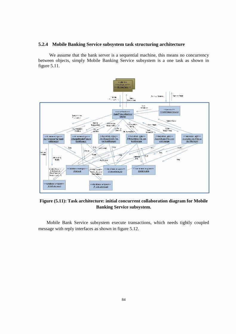
84
5.2.4 Mobile Banking Service subsystem task structuring architecture
We assume that the bank server is a sequential machine, this means no concurrency between objects, simply Mobile Banking Service subsystem is a one task as shown in figure 5.11.
Figure (5.11): Task architecture: initial concurrent collaboration diagram for Mobile Banking Service subsystem.
Mobile Bank Service subsystem execute transactions, which needs tightly coupled message with reply interfaces as shown in figure 5.12.
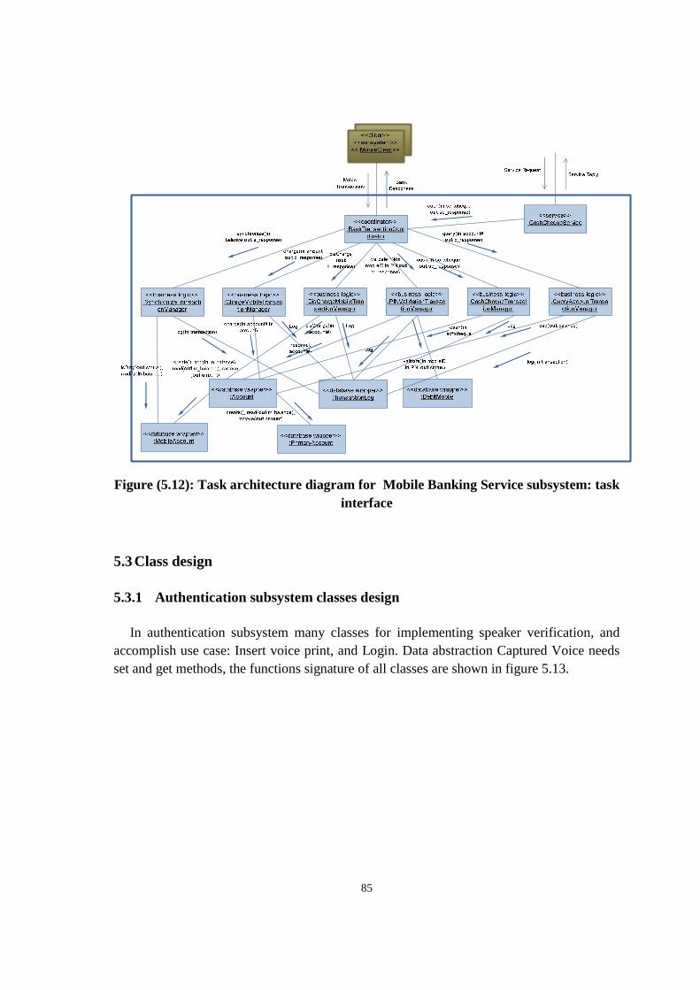
85
Figure (5.12): Task architecture diagram for Mobile Banking Service subsystem: task interface
5.3 Class design
5.3.1 Authentication subsystem classes design
In authentication subsystem many classes for implementing speaker verification, and accomplish use case: Insert voice print, and Login. Data abstraction Captured Voice needs set and get methods, the functions signature of all classes are shown in figure 5.13.
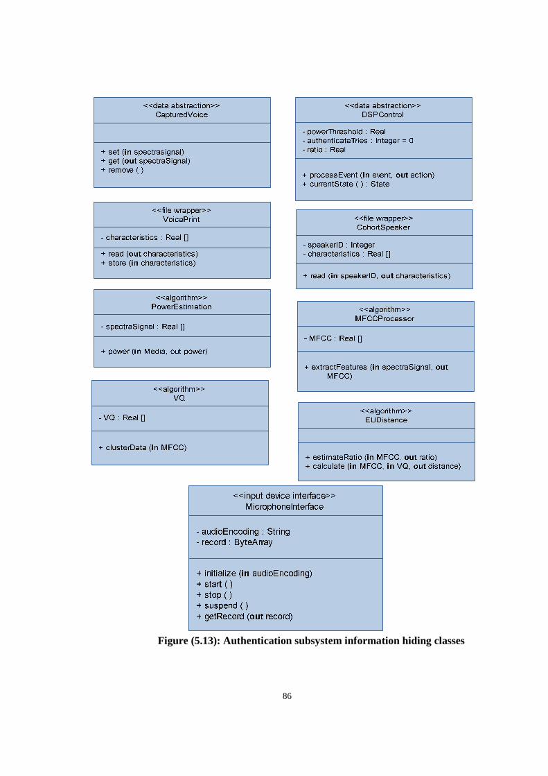
86
Figure (5.13): Authentication subsystem information hiding classes
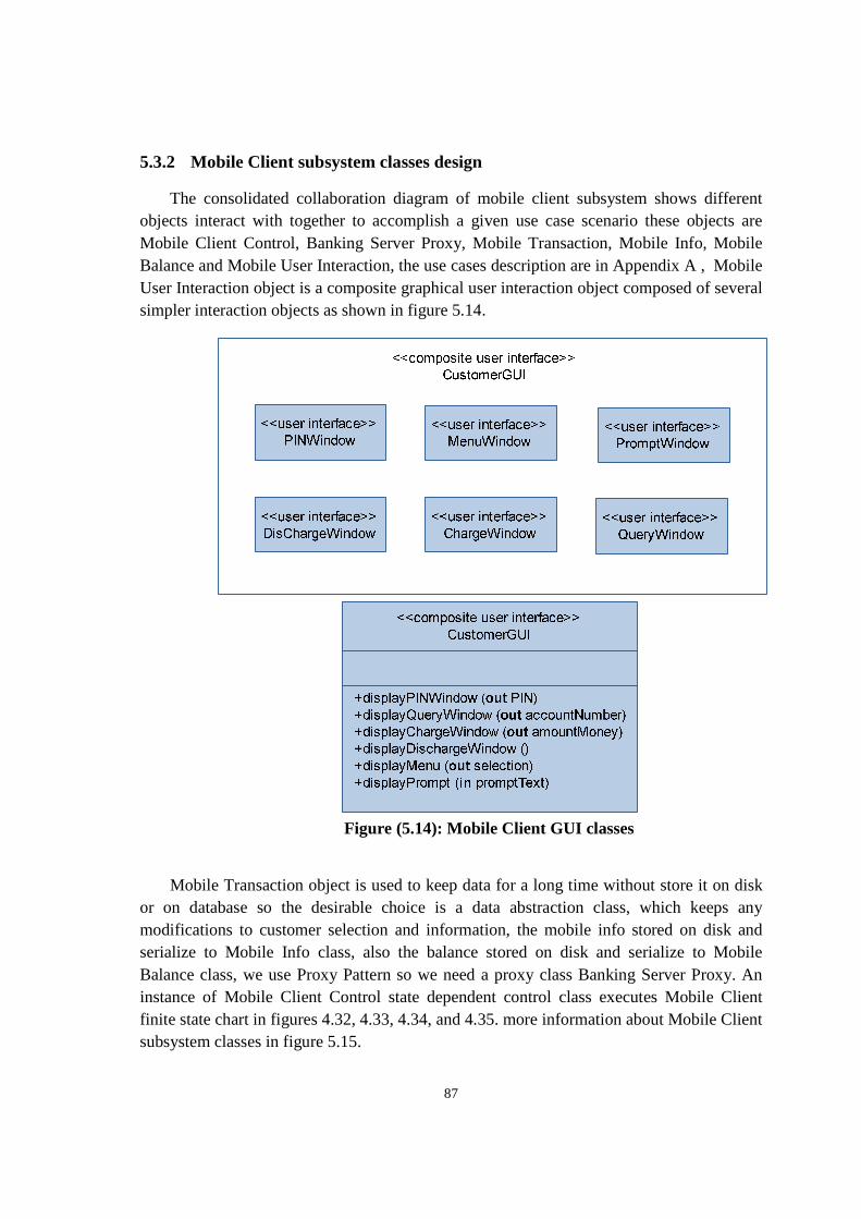
87
5.3.2 Mobile Client subsystem classes design
The consolidated collaboration diagram of mobile client subsystem shows different objects interact with together to accomplish a given use case scenario these objects are Mobile Client Control, Banking Server Proxy, Mobile Transaction, Mobile Info, Mobile Balance and Mobile User Interaction, the use cases description are in Appendix A , Mobile User Interaction object is a composite graphical user interaction object composed of several simpler interaction objects as shown in figure 5.14.
Figure (5.14): Mobile Client GUI classes
Mobile Transaction object is used to keep data for a long time without store it on disk or on database so the desirable choice is a data abstraction class, which keeps any modifications to customer selection and information, the mobile info stored on disk and serialize to Mobile Info class, also the balance stored on disk and serialize to Mobile Balance class, we use Proxy Pattern so we need a proxy class Banking Server Proxy. An instance of Mobile Client Control state dependent control class executes Mobile Client finite state chart in figures 4.32, 4.33, 4.34, and 4.35. more information about Mobile Client subsystem classes in figure 5.15.
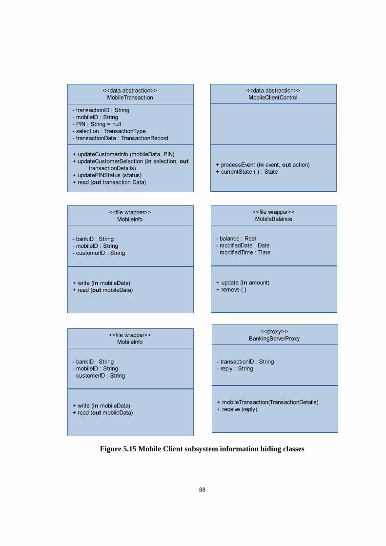
88
Figure 5.15 Mobile Client subsystem information hiding classes
<<data abstraction>>
MobileTransaction
- transactionID : String
- mobileID : String
- PIN : String = null
- selection : TransactionType
- transactionData : TransactionRecord
+ updateCustomerInfo (mobileData, PIN)
+ updateCustomerSelection (in selection, out
transactionDetails)
+ updatePINStatus (status)
+ read (out transaction Data)
<<data abstraction>>
MobileClientControl
+ processEvent (in event, out action)
+ currentState ( ) : State
<<file wrapper>>
MobileInfo
- bankID : String
- mobileID : String
- customerID : String
+ write (in mobileData)
+ read (out mobileData)
<<file wrapper>>
MobileBalance
- balance : Real
- modifiedDate : Date
- modifiedTime : Time
+ update (in amount)
+ remove ( )
<<file wrapper>>
MobileInfo
- bankID : String
- mobileID : String
- customerID : String
+ write (in mobileData)
+ read (out mobileData)
<<proxy>>
BankingServerProxy
- transactionID : String
- reply : String
+ mobileTransaction(TransactionDetails)
+ receive (reply)
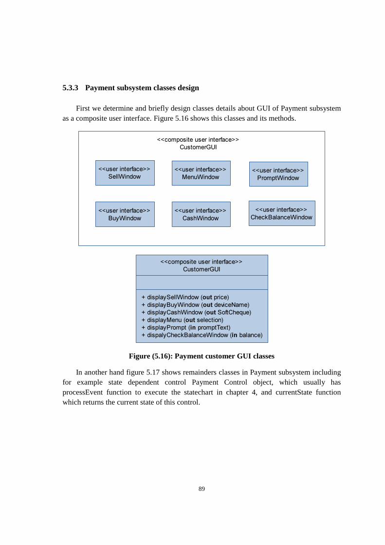
89
5.3.3 Payment subsystem classes design
First we determine and briefly design classes details about GUI of Payment subsystem as a composite user interface. Figure 5.16 shows this classes and its methods.
Figure (5.16): Payment customer GUI classes
In another hand figure 5.17 shows remainders classes in Payment subsystem including for example state dependent control Payment Control object, which usually has processEvent function to execute the statechart in chapter 4, and currentState function which returns the current state of this control.
<<user interface>>
SellWindow<<user interface>>
MenuWindow
<<user interface>>
CashWindow
<<user interface>>
BuyWindow
<<user interface>>
PromptWindow
<<composite user interface>>
CustomerGUI
<<user interface>>
CheckBalanceWindow
<<composite user interface>>
CustomerGUI
+ displaySellWindow (out price)
+ displayBuyWindow (out deviceName)
+ displayCashWindow (out SoftCheque)
+ displayMenu (out selection)
+ displayPrompt (in promptText)
+ dispalyCheckBalanceWindow (in balance)
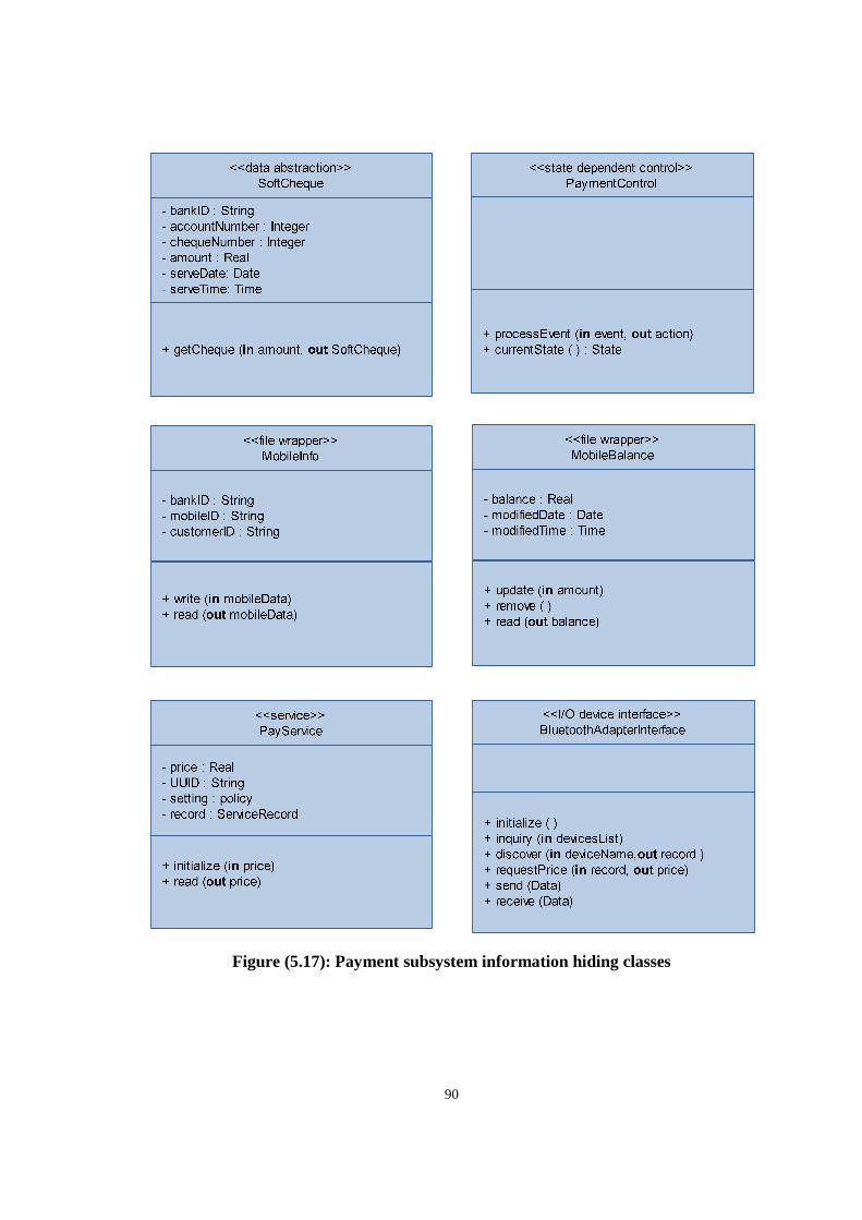
90
Figure (5.17): Payment subsystem information hiding classes
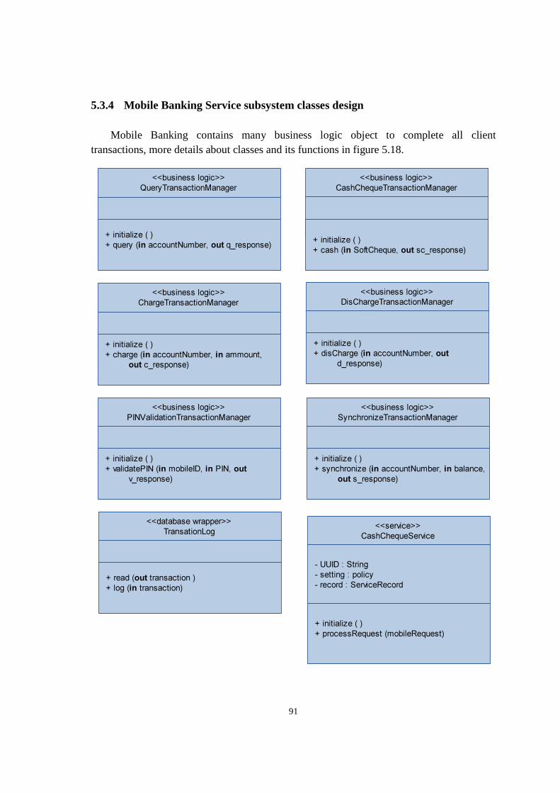
91
5.3.4 Mobile Banking Service subsystem classes design
Mobile Banking contains many business logic object to complete all client transactions, more details about classes and its functions in figure 5.18.
<<business logic>>
QueryTransactionManager
+ initialize ( )
+ query (in accountNumber, out q_response)
<<business logic>>
CashChequeTransactionManager
+ initialize ( )
+ cash (in SoftCheque, out sc_response)
<<business logic>>
ChargeTransactionManager
+ initialize ( )
+ charge (in accountNumber, in ammount,
out c_response)
<<business logic>>
DisChargeTransactionManager
+ initialize ( )
+ disCharge (in accountNumber, out
d_response)
<<business logic>>
PINValidationTransactionManager
+ initialize ( )
+ validatePIN (in mobileID, in PIN, out
v_response)
<<business logic>>
SynchronizeTransactionManager
+ initialize ( )
+ synchronize (in accountNumber, in balance,
out s_response)
<<database wrapper>>
TransationLog
+ read (out transaction )
+ log (in transaction)
<<service>>
CashChequeService
- UUID : String
- setting : policy
- record : ServiceRecord
+ initialize ( )
+ processRequest (mobileRequest)
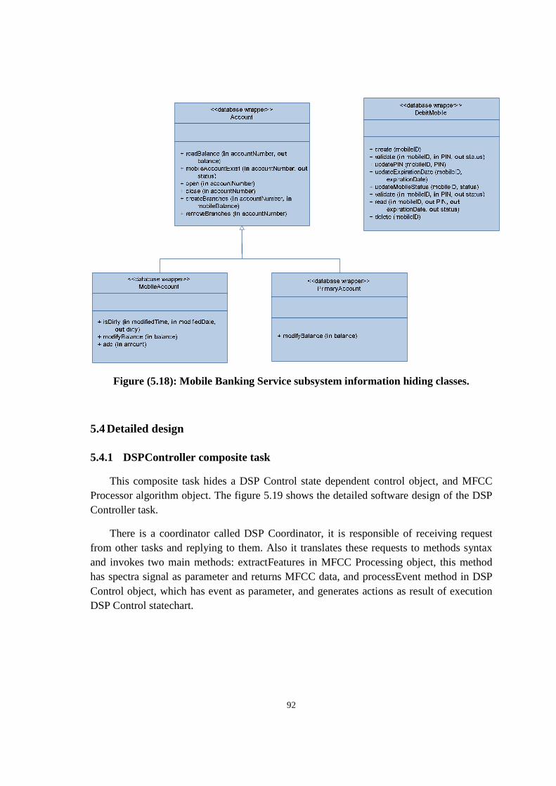
92
Figure (5.18): Mobile Banking Service subsystem information hiding classes.
5.4 Detailed design
5.4.1 DSPController composite task
This composite task hides a DSP Control state dependent control object, and MFCC Processor algorithm object. The figure 5.19 shows the detailed software design of the DSP Controller task.
There is a coordinator called DSP Coordinator, it is responsible of receiving request from other tasks and replying to them. Also it translates these requests to methods syntax and invokes two main methods: extractFeatures in MFCC Processing object, this method has spectra signal as parameter and returns MFCC data, and processEvent method in DSP Control object, which has event as parameter, and generates actions as result of execution DSP Control statechart.
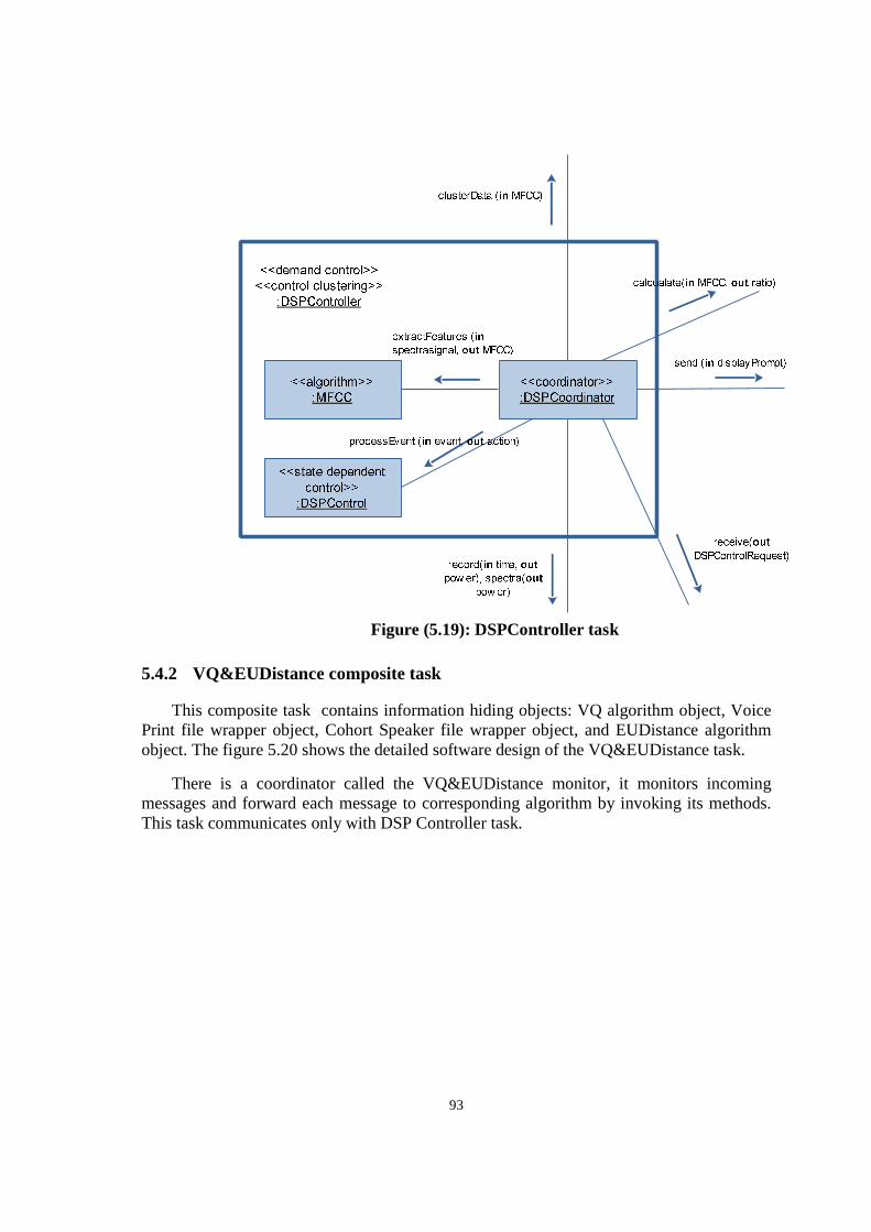
93
Figure (5.19): DSPController task
5.4.2 VQ&EUDistance composite task
This composite task contains information hiding objects: VQ algorithm object, Voice Print file wrapper object, Cohort Speaker file wrapper object, and EUDistance algorithm object. The figure 5.20 shows the detailed software design of the VQ&EUDistance task.
There is a coordinator called the VQ&EUDistance monitor, it monitors incoming messages and forward each message to corresponding algorithm by invoking its methods. This task communicates only with DSP Controller task.
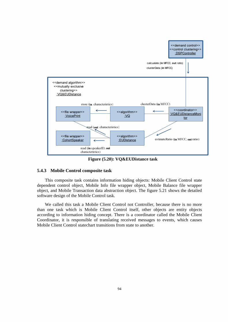
94
Figure (5.20): VQ&EUDistance task
5.4.3 Mobile Control composite task
This composite task contains information hiding objects: Mobile Client Control state dependent control object, Mobile Info file wrapper object, Mobile Balance file wrapper object, and Mobile Transaction data abstraction object. The figure 5.21 shows the detailed software design of the Mobile Control task.
We called this task a Mobile Client Control not Controller, because there is no more than one task which is Mobile Client Control itself, other objects are entity objects according to information hiding concept. There is a coordinator called the Mobile Client Coordinator, it is responsible of translating received messages to events, which causes Mobile Client Control statechart transitions from state to another.
<<algorithm>>
:VQ
<<algorithm>>
:EUDistance
<<coordinator>>
:VQ&EUDistanceMoni
tor
<<file wrapper>>
:VoicePrint
<<file wrapper>>
:CohortSpeaker
store (in characteristics)
read (out characteristics)
read (in speakerID, out
characteristics)
clusterData (in MFCC)
clusterData (in MFCC)
calcualate (in MFCC, out ratio)
estimateRatio (in MFCC, out ratio)
<<demand algorithm>>
<<mutually exclusive
clustering>>
:VQ&EUDistance
<<demand control>>
<<control clustering>>
:DSPController
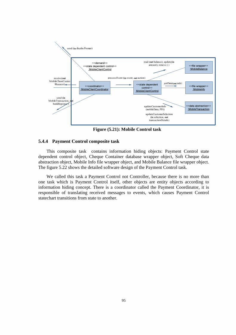
95
Figure (5.21): Mobile Control task
5.4.4 Payment Control composite task
This composite task contains information hiding objects: Payment Control state dependent control object, Cheque Container database wrapper object, Soft Cheque data abstraction object, Mobile Info file wrapper object, and Mobile Balance file wrapper object. The figure 5.22 shows the detailed software design of the Payment Control task.
We called this task a Payment Control not Controller, because there is no more than one task which is Payment Control itself, other objects are entity objects according to information hiding concept. There is a coordinator called the Payment Coordinator, it is responsible of translating received messages to events, which causes Payment Control statechart transitions from state to another.
<<state dependent
control>>
:MobileClientControl
<<file wrapper>>
:MobileBalance
<<file wrapper>>
:MobileInfo
<<data abstraction>>
:MobileTransactionupdateCustomerInfo
(mobileData, PIN)
updateCustomerSelection
(in selection, out
transactionDetails)
getData(out info)
read (out balance), update(in
amount), remove ( )
<<coordinator>>
:MobileClientCoordinator
processEvent (in event, out action) receive(out
MobileClientContro
lRequest)
send (in displayPrompt)
<<demand>>
<<state dependent control>>
:MobileClientControl
send (in
MobileTransaction, out
bankReponse )
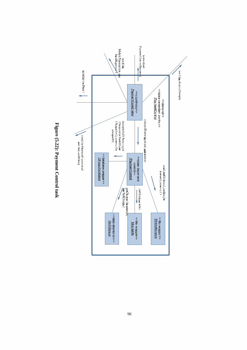
96
Figure (5.22): P
ayment C
ontrol task
97
Chapter 6
SPEAKER VERIFICATION SYSTEM: IMPLEMENTATION, AND EXPERIMENTAL RESULTS
6.1 Recording speech
To capture a voice from the microphone we use the statement:
Player p1 = Manager.createPlayer("capture://audio?encoding=pcm&rate=8000&bits=16&channels=1&endian=big&signed=signed");
This statement contains many parameters that can be specialized for digital signaling:
• Encoding format: we use Pulse Code Modulation [54], encodes an audio waveform in the time domain as a series of amplitudes.
• Rate: or frequency This parameter measures how many samples/channel are played each second. Frequency is measured in samples/second (Hz).
• Resolution/Sample Size: This parameter specifies the amount of data used to represent each discrete amplitude sample. The most common values are 8 bits (1 byte), which gives a range of 256 amplitude steps, or 16 bits (2 bytes), which gives a range of 65536 amplitude steps.
98
• Channels And Interleaving: If the PCM type is monaural, each sample will belong to that one channel. If there is more than one channel, the channels will almost always be interleaved: Left sample, right sample, left, right, etc., in the case of stereo interleaved data.
• Byte Order: or computer system “Endianness”, When more than one byte is used to represent a PCM sample, the byte order (big endian vs. little endian) must be known. In our statement we have two PCM bytes byte0, and byte1, it is presented in big endian as: byte1byte0 rather than byte0byte1 for small endian system. ARMv6 and above introduces several architectural extensions to support mixed-endian access in hardware. A PSR Endian control flag, the E bit, which dictates the byte order used for the entire load and store [64].
• Sign: It is not enough to know that a PCM sample is, for example, 8 bits wide. Whether the sample is signed or unsigned is needed to understand the range. If the sample is unsigned, the sample range is 0..255 with a center point of 128. If the sample is signed, the sample range is -128..127 with a center point of 0. If a PCM type is signed, the sign encoding is almost always 2's complement. In very rare cases, signed PCM audio is represented as a series of sign/magnitude coded numbers.
6.2 ARM VFP architecture
ARM-11 processor has a vector floating point (VFP), The Vector Floating-Point (VFP) architecture is a coprocessor extension to the ARM® architecture. It provides single-precision and double-precision floating-point arithmetic, as defined by ANSI/IEEE standards.
A complete implementation of the VFP architecture must include a software component, known as support code. The support code provides the features of the IEEE 754[19] compliance that are not supplied by the hardware [64].
Double-precision format: A double-precision value consists of two 32-bit words, with the following formats:
1. Most significant word:
31 30 20 19 0
S Exponent Fraction [51:32]
2. Least significant word:
31 0
Fraction [31:0]
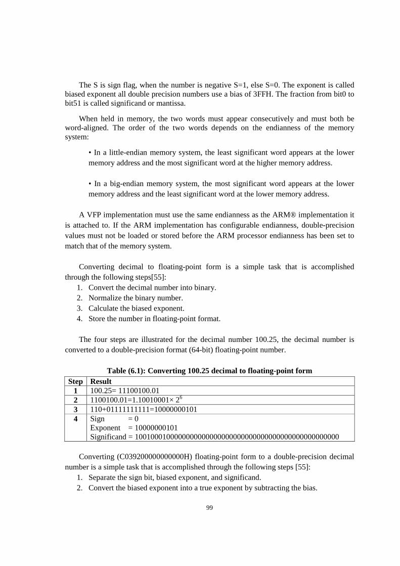
99
The S is sign flag, when the number is negative S=1, else S=0. The exponent is called biased exponent all double precision numbers use a bias of 3FFH. The fraction from bit0 to bit51 is called significand or mantissa.
When held in memory, the two words must appear consecutively and must both be word-aligned. The order of the two words depends on the endianness of the memory system:
• In a little-endian memory system, the least significant word appears at the lower memory address and the most significant word at the higher memory address. • In a big-endian memory system, the most significant word appears at the lower memory address and the least significant word at the lower memory address.
A VFP implementation must use the same endianness as the ARM® implementation it is attached to. If the ARM implementation has configurable endianness, double-precision values must not be loaded or stored before the ARM processor endianness has been set to match that of the memory system. Converting decimal to floating-point form is a simple task that is accomplished through the following steps[55]:
1. Convert the decimal number into binary. 2. Normalize the binary number. 3. Calculate the biased exponent. 4. Store the number in floating-point format.
The four steps are illustrated for the decimal number 100.25, the decimal number is converted to a double-precision format (64-bit) floating-point number.
Table (6.1): Converting 100.25 decimal to floating-point form Step Result
1 100.25= 11100100.01 2 1100100.01=1.10010001× 26 3 110+01111111111=10000000101 4 Sign = 0
Exponent = 10000000101 Significand = 1001000100000000000000000000000000000000000000000000
Converting (C039200000000000H) floating-point form to a double-precision decimal number is a simple task that is accomplished through the following steps [55]:
1. Separate the sign bit, biased exponent, and significand. 2. Convert the biased exponent into a true exponent by subtracting the bias.
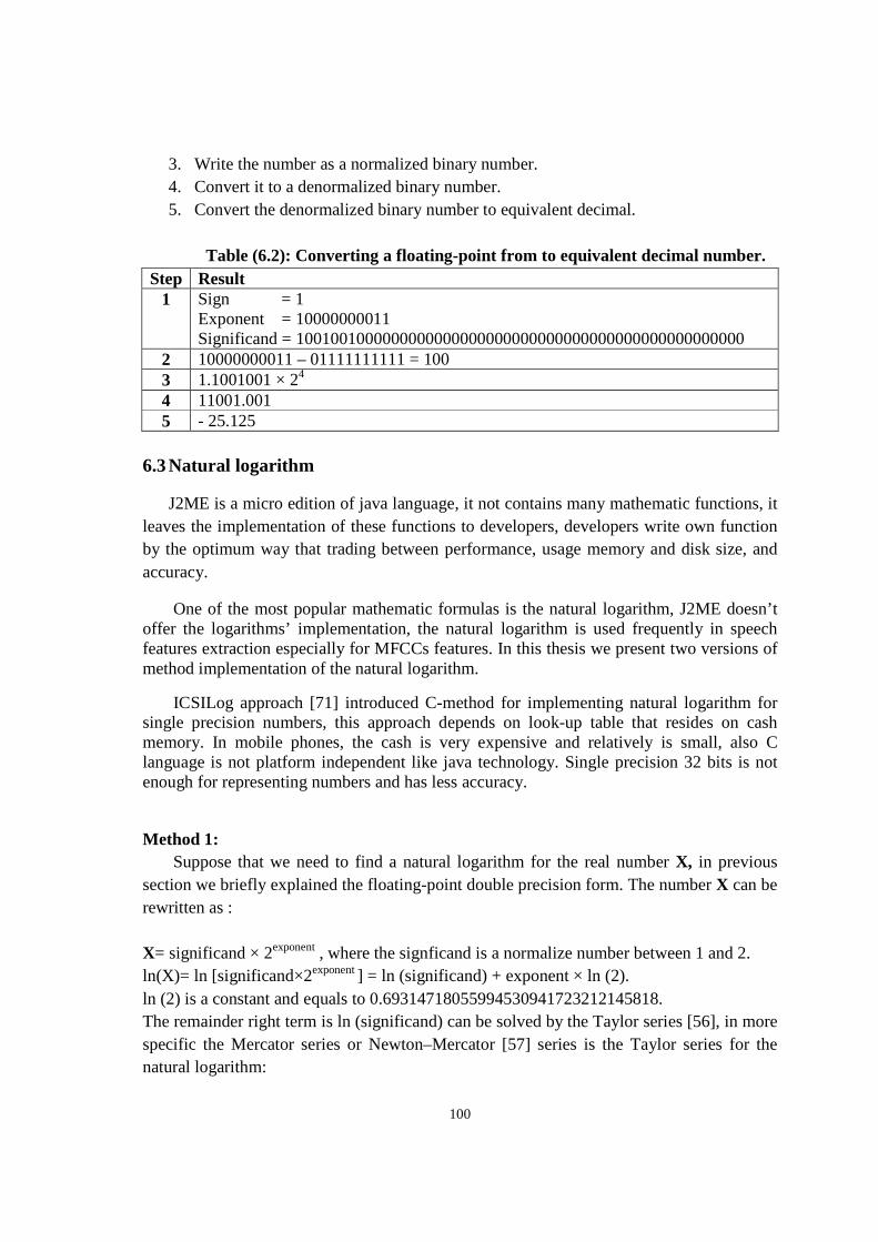
100
3. Write the number as a normalized binary number. 4. Convert it to a denormalized binary number. 5. Convert the denormalized binary number to equivalent decimal.
Table (6.2): Converting a floating-point from to equivalent decimal number.
Step Result 1 Sign = 1
Exponent = 10000000011 Significand = 1001001000000000000000000000000000000000000000000000
2 10000000011 – 01111111111 = 100 3 1.1001001 × 24 4 11001.001 5 - 25.125
6.3 Natural logarithm
J2ME is a micro edition of java language, it not contains many mathematic functions, it leaves the implementation of these functions to developers, developers write own function by the optimum way that trading between performance, usage memory and disk size, and accuracy.
One of the most popular mathematic formulas is the natural logarithm, J2ME doesn’t offer the logarithms’ implementation, the natural logarithm is used frequently in speech features extraction especially for MFCCs features. In this thesis we present two versions of method implementation of the natural logarithm.
ICSILog approach [71] introduced C-method for implementing natural logarithm for single precision numbers, this approach depends on look-up table that resides on cash memory. In mobile phones, the cash is very expensive and relatively is small, also C language is not platform independent like java technology. Single precision 32 bits is not enough for representing numbers and has less accuracy.
Method 1: Suppose that we need to find a natural logarithm for the real number X, in previous section we briefly explained the floating-point double precision form. The number X can be rewritten as : X= significand × 2exponent , where the signficand is a normalize number between 1 and 2. ln(X)= ln [significand×2exponent ] = ln (significand) + exponent × ln (2). ln (2) is a constant and equals to 0.69314718055994530941723212145818. The remainder right term is ln (significand) can be solved by the Taylor series [56], in more specific the Mercator series or Newton–Mercator [57] series is the Taylor series for the natural logarithm:
101
ln1 + � = ∑ �������
,|| < 1�
��
= −��
�+
��
�−
��
�+⋯ ((6.1))
We have implemented the natural logarithm depends on Mercator series in the following J2ME code:
public static double mercatorLog(double x) { long l = Double.doubleToLongBits(x); long exp = ((0x7ff0000000000000L & l) >> 52) - 1023; double man = (0x000fffffffffffffL & l) / (double)0x10000000000000L + 1.0; double lnm = 0; double a = (man - 1); for( int n = 1; n < 7; n ++) { if (n%2!=0) lnm += pow(a, n) / n; else lnm -=pow(a,n)/n;
} return lnm + exp * 0.69314718055994530941723212145818;
}
For more accuracy, increase the range of “for loop” . And we need to implement the power method too, because is not defined in J2ME:
public static double pow(double base, int exp){
if(exp == 0) return 1;
double res = base;
for(;exp > 1; --exp)
res *= base;
return res;
}
Method 2
102
Because the significand is in normalized form: 1.XXX, so it can be written as : 1+X where X is between 0 and 1, so there is another more efficient series based on the Area Hyperbolic Tangent function [58] can be applied for natural logarithm estimation:
ln� = 2 × ������ℎ ������
, 0 < < 1 ((6.2))
Where,
������ℎ� = � +��
�+
��
�+
��
�+⋯
= ∑ �����
(���)
��� , |�| < 1 ((6.3))
We have implemented the natural logarithm depends on Area hyperbolic tangent function in the following J2ME code:
public static double hyperbolicLog(double x) { long l = Double.doubleToLongBits(x); long exp = ((0x7ff0000000000000L & l) >> 52) - 1023; double man = (0x000fffffffffffffL & l) / (double)0x10000000000000L + 1.0; double lnm = 0.0; double a = (man - 1) / (man + 1); for( int n = 1; n < 7; n += 2) { lnm += pow(a, n) / n; } return 2 * lnm + exp * 0.69314718055994530941723212145818;
} And again we use the implementation of pow formula as in method 1. Method 2 is more accuracy than method 1, but it slower as will be discussed in the results.
Method 3
We implemented a more practical, and very fast natural logarithm method, but of course it is little less accurate than previous methods. The right term in the summation ln(X) = ln (significand) + exponent × ln (2), the term: ln (significand) is between ln (1), and ln(2) or between 0, and 0.69314718055994530941723212145818. In large numbers, the very small right term can be neglected respect to very large left term, the term: exponent × ln (2), and we can write a fast method in J2ME without pow method need.
103
public static double mlog(double x){ long l = Double.doubleToLongBits(x); long exp = ((0x7ff0000000000000L & l) >> 52) - 1023; return exp * 0.69314718055994530941723212145818;
}
6.4 Data privacy
We need to store very sensitive data in mobile storage media like:
1. Mobile info which contains many critical fields like: Mobile ID. 2. Mobile balance which contains: mobile balance, modified date, and modified time. 3. Voice print codebook.
The Java Community Processsm (JCPSM) (see jcp.org) is the mechanism for developing standard technical specifications for Java technology. Anyone can register for the site and participate in reviewing and providing feedback for the Java Specification Requests (JSRs), and anyone can sign up to become a JCP Member and then participate on the Expert Group of a JSR or even submit their own JSR Proposals.
The File Connection Optional Package (FCOP) is one of two optional packages defined by JSR 75 through the Java Community Process. The other, the PIM Optional Package. We use the first package, and to import only needed packages your code must include:
import javax.microedition.io.Connector; import javax.microedition.io.file.FileConnection; JSR 75 provides a mechanism to store data in private folder, and keep this data away from accessing or modifying by another MIDlet. This mechanism is called Private work directory of MIDlet suite by using the string argument “fileconn.dir.private”, suppose we want store a data in a private folder as mobileinfo.txt we do that by the following J2ME code to create the file, and open it for reading, and writing :
import javax.microedition.io.Connector; import javax.microedition.io.file.FileConnection;
String galleryPath = System.getProperty("fileconn.dir.private"); String path = galleryPath + "mobileinfo.txt"; try {
104
FileConnectio fconn = (FileConnection)Connector.open(path,Connector.READ_WRITE); if (!fconn.exists()) fconn.create(); else{ fconn.delete(); fconn.create(); } By this mechanism we protect the application files from manipulate, stolen and remove, the mobile user itself cannot change the mobile balance or ID.
6.5 Natural logarithm methods experiments and results
We tested the three methods for calculating natural logarithm at two ranges of numbers, the first rang is a set of numbers between 10, and 350 as a double values, the range 2 is a set of numbers between 5000, and 10000000 double values. By choosing one rang for small numbers, and another for large numbers we cover many application fields and algorithms [72, 73].
Because most of processors today (Intel, AMD, ARM,…) use the IEEE 754 standard, we can test our methods in personal computer, by this way we can take the java log as reference in measurement as ICSILog approache used C-log in standard Math.h C library. So we simulate our methods on laptop Dell Inspiron 1545, with Intel Core™ 2 Duo 2.00 GHz for each one, the operating system was Microsoft windows 7 Ultimate service pack 1.
We measured the accuracy of the three methods, and by taking the java log as a reference, we assumed that the java log is 100% accurate. Also we compared between the three methods on execution time, we reflected the execution time with the speedup of java log too.
In range 1 The average error rate of method1 and method2 is very small, it is near the zero, but the method3 has a big average error rate, the rate 7.8% effects the results when the numbers are small and does bad performance (figure 6.1).
Also in range 1 method 1 fasters than the java method with 6.5 times, while method2 only with 1.4 times, as an expected, method3 is a faster one, with 10.5 times faster than the java method.
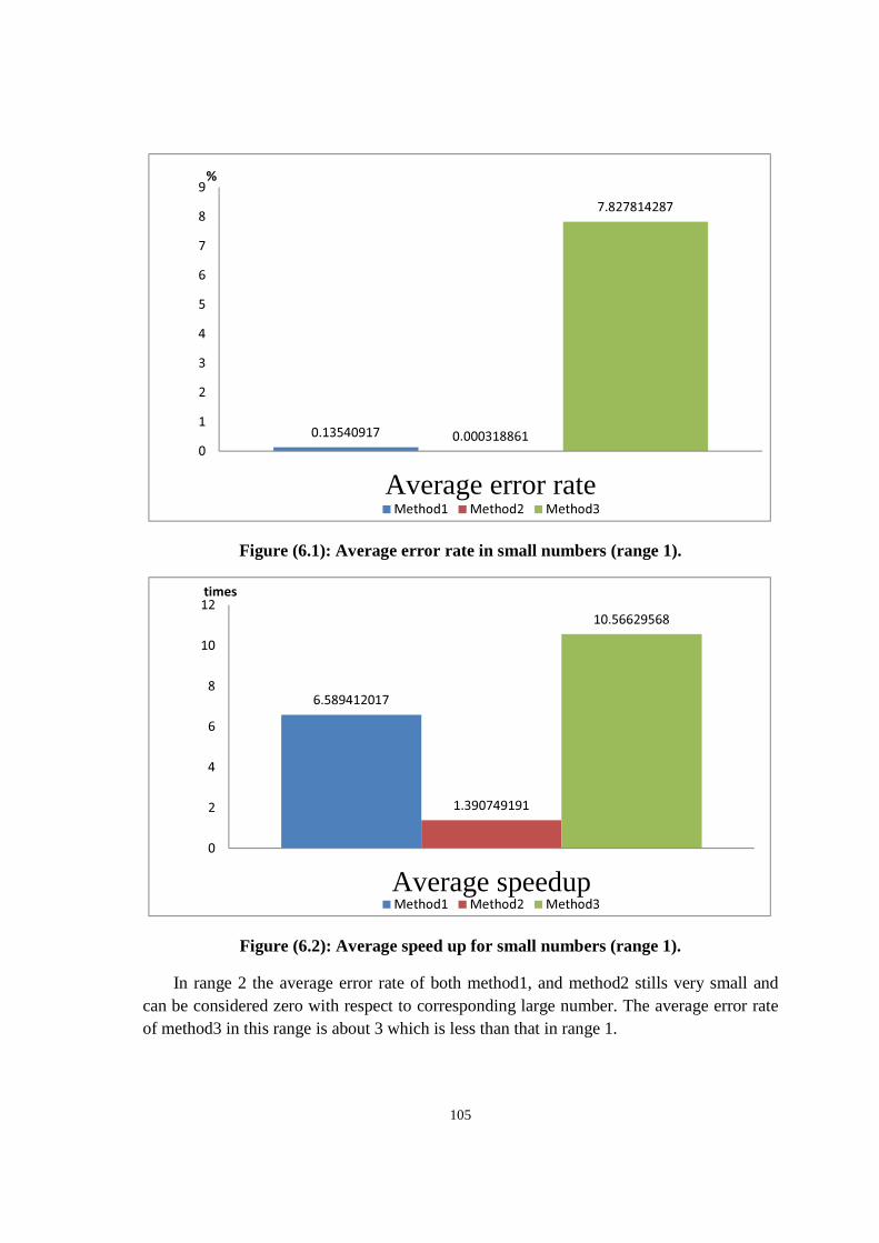
105
Figure (6.1): Average error rate in small numbers (range 1).
Figure (6.2): Average speed up for small numbers (range 1).
In range 2 the average error rate of both method1, and method2 stills very small and can be considered zero with respect to corresponding large number. The average error rate of method3 in this range is about 3 which is less than that in range 1.
0.13540917 0.000318861
7.827814287
0
1
2
3
4
5
6
7
8
9
Average error rate
%
Method1 Method2 Method3
6.589412017
1.390749191
10.56629568
0
2
4
6
8
10
12
Average speedup
times
Method1 Method2 Method3
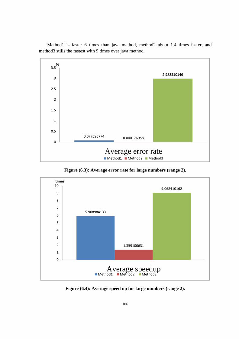
106
Method1 is faster 6 times than java method, method2 about 1.4 times faster, and method3 stills the fastest with 9 times over java method.
Figure (6.3): Average error rate for large numbers (range 2).
Figure (6.4): Average speed up for large numbers (range 2).
0.0775957740.000176958
2.988310146
0
0.5
1
1.5
2
2.5
3
3.5
Average error rate
%
Method1 Method2 Method3
5.908984133
1.359100631
9.068410162
0
1
2
3
4
5
6
7
8
9
10
Average speedup
times
Method1 Method2 Method3
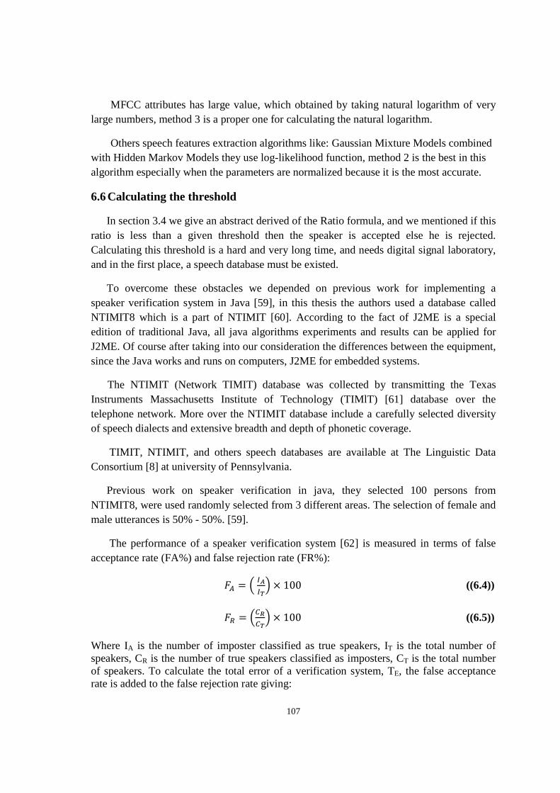
107
MFCC attributes has large value, which obtained by taking natural logarithm of very large numbers, method 3 is a proper one for calculating the natural logarithm.
Others speech features extraction algorithms like: Gaussian Mixture Models combined with Hidden Markov Models they use log-likelihood function, method 2 is the best in this algorithm especially when the parameters are normalized because it is the most accurate.
6.6 Calculating the threshold
In section 3.4 we give an abstract derived of the Ratio formula, and we mentioned if this ratio is less than a given threshold then the speaker is accepted else he is rejected. Calculating this threshold is a hard and very long time, and needs digital signal laboratory, and in the first place, a speech database must be existed.
To overcome these obstacles we depended on previous work for implementing a speaker verification system in Java [59], in this thesis the authors used a database called NTIMIT8 which is a part of NTIMIT [60]. According to the fact of J2ME is a special edition of traditional Java, all java algorithms experiments and results can be applied for J2ME. Of course after taking into our consideration the differences between the equipment, since the Java works and runs on computers, J2ME for embedded systems.
The NTIMIT (Network TIMIT) database was collected by transmitting the Texas Instruments Massachusetts Institute of Technology (TIMlT) [61] database over the telephone network. More over the NTIMIT database include a carefully selected diversity of speech dialects and extensive breadth and depth of phonetic coverage.
TIMIT, NTIMIT, and others speech databases are available at The Linguistic Data Consortium [8] at university of Pennsylvania.
Previous work on speaker verification in java, they selected 100 persons from NTIMIT8, were used randomly selected from 3 different areas. The selection of female and male utterances is 50% - 50%. [59].
The performance of a speaker verification system [62] is measured in terms of false acceptance rate (FA%) and false rejection rate (FR%):
�� = ���� × 100 ((6.4))
� = �!�!� × 100 ((6.5))
Where IA is the number of imposter classified as true speakers, IT is the total number of speakers, CR is the number of true speakers classified as imposters, CT is the total number of speakers. To calculate the total error of a verification system, TE, the false acceptance rate is added to the false rejection rate giving:
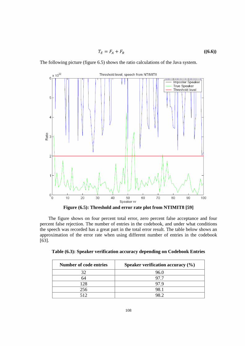
108
�� � �� � �� ((6.6))
The following picture (figure 6.5) shows the ratio calculations of the Java system.
Figure (6.5): Threshold and error rate plot from NTIMIT8 [59]
The figure shows on four percent total error, zero percent false acceptance and four percent false rejection. The number of entries in the codebook, and under what conditions the speech was recorded has a great part in the total error result. The table below shows an approximation of the error rate when using different number of entries in the codebook [63].
Table (6.3): Speaker verification accuracy depending on Codebook Entries
Number of code entries Speaker verification accuracy (%)
32 96.0 64 97.7 128 97.9 256 98.1 512 98.2
109
Chapter 7
CONCLUSION AND FUTURE WORK
7.1 Conclusion
In this thesis, we have proposed a new approach for M-Commerce named Debit Mobile, that is a phone-based J2ME application payment technology, and enables a bank’s customer to query his account balance, charge his mobile, and discharge his mobile. A mobile customer who owns debit mobile can easily pay for services or products, via transferring a novel proposed Cheque, called a soft Cheque.
We introduce a new mechanism for query account, and put pseudo codes for query, charge mobile, discharge mobile, and synchronize balances operations. Also we structured a new digital certificate format suited with mobile phones.
We have introduces a new scenario of transferring, and cash the soft Cheque, with no third party, or a connection to the bank server for verifying it in payment case. This scenario depends on proposed digital certificate.
We modeled our system with COMET method, our model contains analysis model which consists of static and dynamic modeling, subsystem structuring, object structuring, and control objects composite statecharts. And also contains design model which consists of consolidated collaboration modeling, system architectural design, concurrent task structuring with clustering criteria, and detailed design.
Also we have developed a software component for voice authentication depends on speaker verification algorithms, we have chosen algorithms, and modified them to be able to work on mobile phones equipment.
We suggested an exist way to calculate the ratio for speaker-verification java systems, and experimental results show that is no fear of false acceptance and also false rejection can be decreased with increasing of codebook size.
110
In speaker verification implementation we implemented natural logarithm with three methods, we compared between them by taking java log as reference, our methods are very fast and suitable with mobile devices.
7.2 Future work
We plan to propose the Debit Mobile system as a new Bluetooth profile to be included in the new versions of Bluetooth, and introduce it to Bluetooth Special Interest Group (SIG) (Bluetooth.org). By this way many applications can be developed for Bluetooth marketing and payment applications such as NFC applications.
DSP is a hot computer engineer field, many complex algorithms can be implemented as a cheap hardware chips. For example FFT radix-4 is an important and complex algorithm for time domain to frequency domain signal transformation, it is implemented as a special form of butterfly called dragonfly [65], also many modern industries for implementing FFT are available (e.g. xilinx.com ).
Although our beloved Palestine has small area, there are many dialects of Arabic, and so there is a real need for a database of speech contains all of these accents, in fact, there are a few Arabian countries has its database of speech e.g. Saudi Arabia [66].
111
REFERENCES
[1] Tiwari, R.; Buse, S. (2007). The Mobile Commerce Prospects: A strategic analysis of opportunities in the banking sector (PDF). Hamburg: Hamburg University Press. p. 33. ISBN 978-3-937816-31-9.
[2] E Turban, D King, J Lee, M Warkentin, H Chung, “Electronic Commerce-A Managerial Perspective", 2010.
[3] Ron Vetter, "Authentication by Biometric Verification," Computer, vol. 43, no. 2, pp. 28-29, Feb. 2010, doi:10.1109/MC.2010.31.
[4] Elisabeth Zetterholm, Voice Imitation. A Phonetic Study of Perceptual Illusions and
Acoustic Success. Phd thesis, Lund University, (2003). [5] Homayoon Beigi, ``Speaker Recognition, Biometrics / Book 1, Jucheng Yang (ed.),
Intech Open Access Publisher, 2011, pp. 3-28, ISBN: 978-953-307-618-8. [6] E. Valcourt, J. Robert, & F. Beaulieu, (2005). Investigating mobile payment:
supporting technologies, methods, and use. IEEE International Conference on Wireless And Mobile Computing, Networking And Communications, (WiMob'2005), Aug. 2005 Page(s):29 - 36 Vol. 4 Digital Object Identifier 10.1109/WIMOB.2005.1512946.
[7] Visa and SK Telecom to launch mobile payments Card Technology Today, Volume
19, Issue 2, Page 6, February 2007. [8] J. Ondrus & Y. Pigneur, “An Assessment of NFC for Future Mobile Payment
Systems. International Conference on the Management of Mobile Business”, 2007, 9-11 July 2007 Page(s):43 - 53 Digital Object Identifier 10.1109/ICMB.2007.9.
[9] GSM Association aims for global mobile payments using NFC Card Technology
Today, Volume 19, Issue 2, February 2007, Pages 1, 3.
[10] S. Karnouskos & F. Fokus (2004). Mobile Payment: a journey through existing procedures and standardization initiatives, IEEE Communications Surveys and Tutorials. 6(4) 44-66.
[11] Adrian Pocovnicu, “Biometric Security for Cell Phones”, Informatica Economică vol. 13, no. 1/2009.
112
[12] E Turban, D King, J Lee, M Warkentin, H Chung, “Electronic Commerce-A Managerial Perspective", 2008.
[13] Ecma International: Standard ECMA-352, Near Field Communication Interface and Protocol–2 (NFCIP-2), December 2003.
[14] "About Clipper". Clippercard.com. Retrieved December 29, 2011.
[15] http://www.bart.gov/news/articles/2009/news20090325.aspx. BART website. May 8, 2009. Retrieved November 16, 2011.
[16] https://www.clippercard.com/ClipperWeb/index.do. Retrieved December 18, 2011.
[17] http://web.archive.org/web/20070817035607/http:/cubic.com/cts/PressReleases/Feb 24-2004.htm. Cubic Transportation Systems, Inc. February 24, 2004. Archived from the original on August 17, 2007. Retrieved November 16, 2011.
[18] ISO Data elements and interchange formats, ISO 8601, 1988, 2004 modified.
[19] IEEE Standard for Floating-Point Arithmetic, IEEE standard 754, 2008.
[20] Topley, Kim , “J2ME in a Nutshell”. O'Reilly Media 2002 . pp. 46– 47. ISBN 9780596002534.
[21] http://eur-lex.europa.eu/LexUriServ/LexUriServ.do. Official Journal L 013 , 19/01/2000 P. 0012 - 0020. Annex II. Retrieved 2010-02-17.
[22] Internet X.509 Public Key Infrastructure: Certification Path Building, RFC 4158, 2005.
[23] Housley, R., W. Ford, W. Polk and D. Solo, "Internet X.509 Public Key Infrastructure: Certificate and CRL Profile", RFC 3280, April 2002. Obsoleted by RFC 5280, Obsoletes RFC 2459/ updated by RFC 4325, RFC 4630.
[24] Knuth, Donald, “The Art of Computer Programming”, volume 3, Sorting and Searching. pp. 506–542. (1973). ISBN 0-201-85393-0.
[25] Kalker, J. Haitsma, and J. Oostveen, “Robust audio hashing for content identification”, Int. Workshop on Content Based Multimedia Indexing, Brescia, Italy, September 19-21, 2001.
[26] A. Z. Broder, “Some applications of Rabin's fingerprinting method”. In Sequences II: Methods in Communications, Security, and Computer Science, pp. 143–152. Springer-Verlag, 1993.
[27] Bret Mulvey, http://home.comcast.net/~bretm/hash/8.html, in Hash Functions. Accessed November 11, 2011.
113
[28] Bret Mulvey, http://home.comcast.net/~bretm/hash/9.html, in Hash Functions. Accessed
November 11, 2011.
[29] UMAC: Message Authentication Code using Universal Hashing, RFC 4418, 2006.
[30] Lawrence Rabiner and Biing-Hwang Juang,” Fundamental of Speech Recognition”, Prentice-Hall, Englewood Cliffs, N.J., 1993.
[31] Sara Rydin.”Text dependent and text independent speaker verification systems. technology and applications”. Term paper in Speech Technology 2001.
[32] P. Kroon and W. B. Kleijn, “Linear-prediction based analysis-by-synthesis coding”, in Speech Coding and Synthesis, Elsevier Science B.V., ch. 3, pp.79–119, 1995.
[33] T. Claes, I. Dologlou, L. ten Bosch, D. Van Compernolle, “A novel feature transformation for vocal tract length normalization in automatic speech recognition”, IEEE transactions on speech and audio processing, vol. 6, no. 6, pp. 549-557, November 1998.
[34] H. Hermansky, "Perceptual linear predictive (PLP) analysis of speech", J. Acoust. Soc. Am., vol. 87, no. 4, pp. 1738-1752, Apr. 1990.
[35] Wolf, J. J. (1972) “Efficient acoustic parameters for speaker recognition”, J.A.S.A. 51, pages 2044-2056.
[36] Md. Rashidul Hasan, Mustafa Jamil, Md. Golam Rabbani Md. Saifur Rahman, “Speaker Identification Using Mel Frequency Cepstral Coefficients”, 3rd Proceedings of International Conference on Electrical & Computer Engineering , ICECE 2004, 28-30 December 2004, Dhaka, Bangladesh,pp 565-568.
[37] Ben J. Shannon, Kuldip K. Paliwal.: A Comparative Study of Filter Bank Spacing for Speech Recognition. In: Microelectronic Engineering Research Conference 2003.
[38] Ziyou Xiong, Regunathan Radhakrishnan, Ajay Divakaran, Thomas S. Huang., “Comparing MFCC and MPEG-7 Audio Features for Feature Extraaction, Maximum Likelihood HMM and Entropic Prior HMM for Sports Audio Classification”, MITSUBISHI Electric Research Laboratories TR2004-082 December 2003.
[39] Matsui, T., Furui, S., “Comparison of text-independent speaker recognition methods using VQ-distortion and discrete/continuous HMMs”, Acou, Speech,and Signal Processing, 1992. ICASSP-92., Volume: 2 , 1992.
114
[40] Linde, Y., Buzo A., Gray, R. M., “An algorithm for vector quantizer design”, IEEE Trans. on Comm., Vol. COM-28, pp. 84-95, Jan. 1980.
[41] Wilson González, Georgina; Karpagam Sankaran (September 10, 1997).
"Hypothesis Testing". Environmental Sampling & Monitoring Primer. Virginia Tech.
[42] K. Fukunaga.” Introduction to Statistical Pattern Recognition”. Academic Press, London, second edition, 1990.
[43] R. Duda, P. Hart, and D. Stork. Pattern Classification. Wiley Interscience, New York, second edition, 2000.
[44] F. Bimbot, M. Blomberg, L. Boves, D. Genoud, H.-P. Hutter, C. Jaboulet, J. Koolwaaij, J. Lindberg, and J.-B. Pierrot. An overview of the CAVE project research activities in speaker verification. Speech Communications, 31:155–180, 2000.
[45] R. Auckenthaler, M. Carey, and H. Lloyd-Thomas. Score normalization for text- independent speaker verification systems. Digit. Sign. Proc., 10:42–54, 2000.
[46] W.D. Zhang, M.W. Mak, and M.X. He. “A two-stage scoring method combining world and cohort models for speaker verification”. In Proc. ICASSP 2000, volume II, pages 1193–1196.
[47] Hassan Gomaa, “Software Modeling and Design UML, Use Cases, Patterns, and Software Architectures:, Cambridge university press 2011. ISBN 978-0-521- 76414-8 Hardback.
[48] Scott W. Ambler (2009) UML 2 Class Diagrams. Webdoc 2003-2009. Accessed Dec 2, 2009.
[49] Holub Associates: UML Reference Card, Version 2.1.2: August 2007. Retrieved 12 March 2011.
[50] OMG Unified Modeling Language (OMG UML) Superstructure, Version 2.3: May 2010. Retrieved 23 September 2010.
[51] M. Jackson, Software Requirements and Specifications. Addison-Wesley Professional, 1995.
[52] M. Jackson, Problem Frames: Analyzing and Structuring Software Development Problems. Addison-Wesley Professional, 2000.
115
[53] Hongqing Sun Developing User-Centric Software Requirements Specifications master thesis.
[54] U.S. patent number 1,608,527; also see p. 8, Data conversion handbook, Walter
Allan Kester, ed., Newnes, 2005, ISBN 0750678410.
[55] Barry B. Brey, “Programing the 80286, 80386, 80486. And Pentium-based personal computer” , Prentice-Hall 1996, ISBN 0023142634.
[56] Abramowitz, Milton; Stegun, Irene A. (1970), Handbook of Mathematical
Functions with Formulas, Graphs, and Mathematical Tables, New York: Dover Publications, Ninth printing.
[57] Medina, Luis A.; Moll, Victor H.; Rowland, Eric S. (2009). "Iterated primitives of
logarithmic powers". arXiv:0911.1325.
[58] As stated by Jan Gullberg, Mathematics: From the Birth of Numbers (New York: W. W. Norton & Company, 1997), ISBN 039304002X, p. 539.
[59] Speaker verification Nilsson Magnus, October 2001, Speaker Verification in JAVA, A thesis submitted in partial fulfillment of the requirements for the degree of Master of Computer and Information Engineering, School of Microelectronic Engineering, Griffith University.
[60] Charles Jankowski, Ashok Kalyanwamy, Sara Basson, and Judith Spitz, “NTIMIT: A Phonetically Balanced, Continuous Speech, Telephone Bandwidth Speech Database”, proc. International conference. Acoustic speech signal process IEEE may 1995 PP. 357-360.
[61] http://www.ldc.upenn.edu/. Retrieved November 20 2011.
[62] Sanderson, C., “Joint Cohort Normalization in a Multi-Feature Speaker Verification System”, submitted to The 10th IEEE International Conference on Fuzzy Systems, Melbourne, Australia, 2-5 December 2001.
[63] Matsui, T., Furui, S., “Comparison of text-independent speaker recognition methods using VQ-distortion and discrete/continuous HMMs”, Acou, Speech, and Signal Processing, 1992. ICASSP-92., Volume: 2 , 1992.
[64] “ARM architecture reference manual”. Arm.com. Retrieved 2011-11-14.
[65] Nilsson, M., “FFT, Realization and Implementation in FPGA”, Master thesis, Ericsson Microwave Systems AB / Griffith University, 2000 – 2001.
116
[66] Computer and Electronics Research Institute, King Abdulaziz City for Science and Technology. “Saudi Accented Arabic Voice Bank (SAAVB)”. 2003.
[67] Hassan Gomaa, Designing Concurrent, “Distributed, and Real-Time Applications with UML”, Addison-Wesley 8th printing 2008. ISBN 0-201-65793-7.
[68] Jacobson, I., G. Booch, and J. Rumbaugh. “The Unified Software Development Process. Reading, Mass.: Addison-Wesley, 1999.
[69] Boehm, B. W. “ A Spiral model of software development and enhancement”. IEEE Computer 21, no. 5 (May 1988): p 61-72.
[70] GSM 04.90 (ETSI EN 300 957, V7.0.1) Specification (USSD) – Stage 3 at 3Gpp.org.
[71] O. Vinyals, G. Friedland, N. Mirghafori, “Revisiting a basic function on current CPUs: A fast logarithm implementation with adjustable accuracy”, International computer science institute, TR-07-002 June 2007.
[72] Ricciardi, Luigi M. (1990), Lectures in applied mathematics and informatics, Manchester: Manchester University Press, ISBN 978-0-7190-2671-3, p. 21, section 1.3.2.
[73] Priya Hemenway, Divine Proportion: Φ Phi in Art, Nature, and Science. Sterling Publishing Co, 2005. ISBN 1402735227.
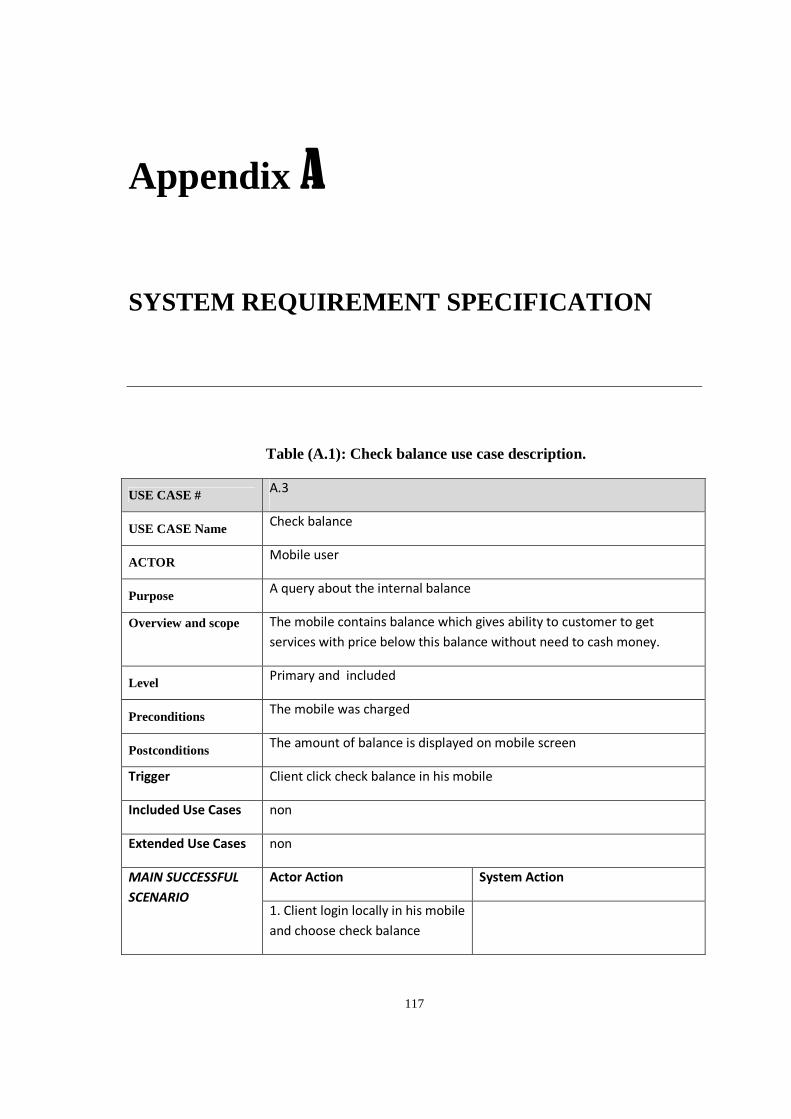
117
Appendix A
SYSTEM REQUIREMENT SPECIFICATION
Table (A.1): Check balance use case description.
USE CASE # A.3
USE CASE Name Check balance
ACTOR Mobile user
Purpose A query about the internal balance
Overview and scope
The mobile contains balance which gives ability to customer to get
services with price below this balance without need to cash money.
Level Primary and included
Preconditions The mobile was charged
Postconditions The amount of balance is displayed on mobile screen
Trigger Client click check balance in his mobile
Included Use Cases non
Extended Use Cases non
MAIN SUCCESSFUL
SCENARIO
Actor Action System Action
1. Client login locally in his mobile
and choose check balance
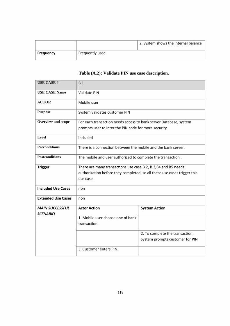
118
2. System shows the internal balance
Frequency Frequently used
Table (A.2): Validate PIN use case description.
USE CASE # B.1
USE CASE Name Validate PIN
ACTOR Mobile user
Purpose System validates customer PIN
Overview and scope For each transaction needs access to bank server Database, system
prompts user to inter the PIN code for more security.
Level included
Preconditions There is a connection between the mobile and the bank server.
Postconditions The mobile and user authorized to complete the transaction .
Trigger There are many transac ons use case B.2, B.3,B4 and B5 needs
authorization before they completed, so all these use cases trigger this
use case.
Included Use Cases non
Extended Use Cases non
MAIN SUCCESSFUL
SCENARIO
Actor Action System Action
1. Mobile user choose one of bank
transaction.
2. To complete the transac on,
System prompts customer for PIN
3. Customer enters PIN.
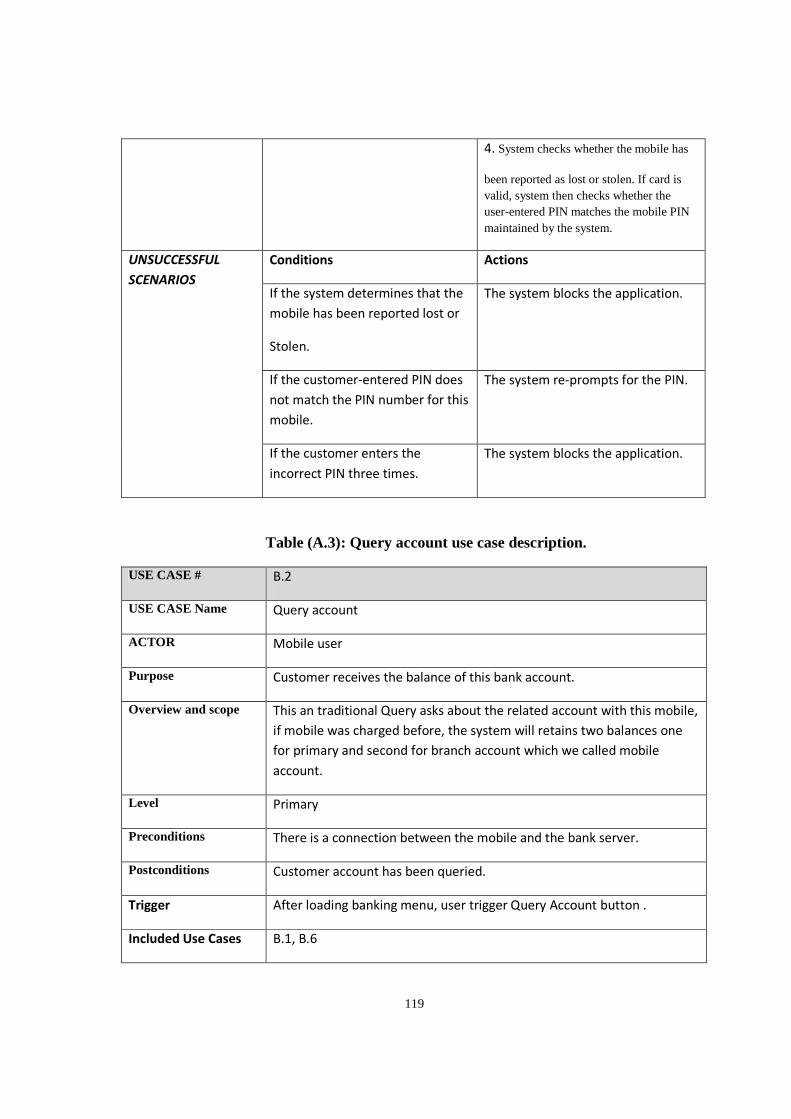
119
4. System checks whether the mobile has
been reported as lost or stolen. If card is valid, system then checks whether the user-entered PIN matches the mobile PIN maintained by the system.
UNSUCCESSFUL
SCENARIOS
Conditions Actions
If the system determines that the
mobile has been reported lost or
Stolen.
The system blocks the application.
If the customer-entered PIN does
not match the PIN number for this
mobile.
The system re-prompts for the PIN.
If the customer enters the
incorrect PIN three times.
The system blocks the application.
Table (A.3): Query account use case description.
USE CASE # B.2
USE CASE Name Query account
ACTOR Mobile user
Purpose Customer receives the balance of this bank account.
Overview and scope This an traditional Query asks about the related account with this mobile,
if mobile was charged before, the system will retains two balances one
for primary and second for branch account which we called mobile
account.
Level Primary
Preconditions There is a connection between the mobile and the bank server.
Postconditions Customer account has been queried.
Trigger After loading banking menu, user trigger Query Account button .
Included Use Cases B.1, B.6
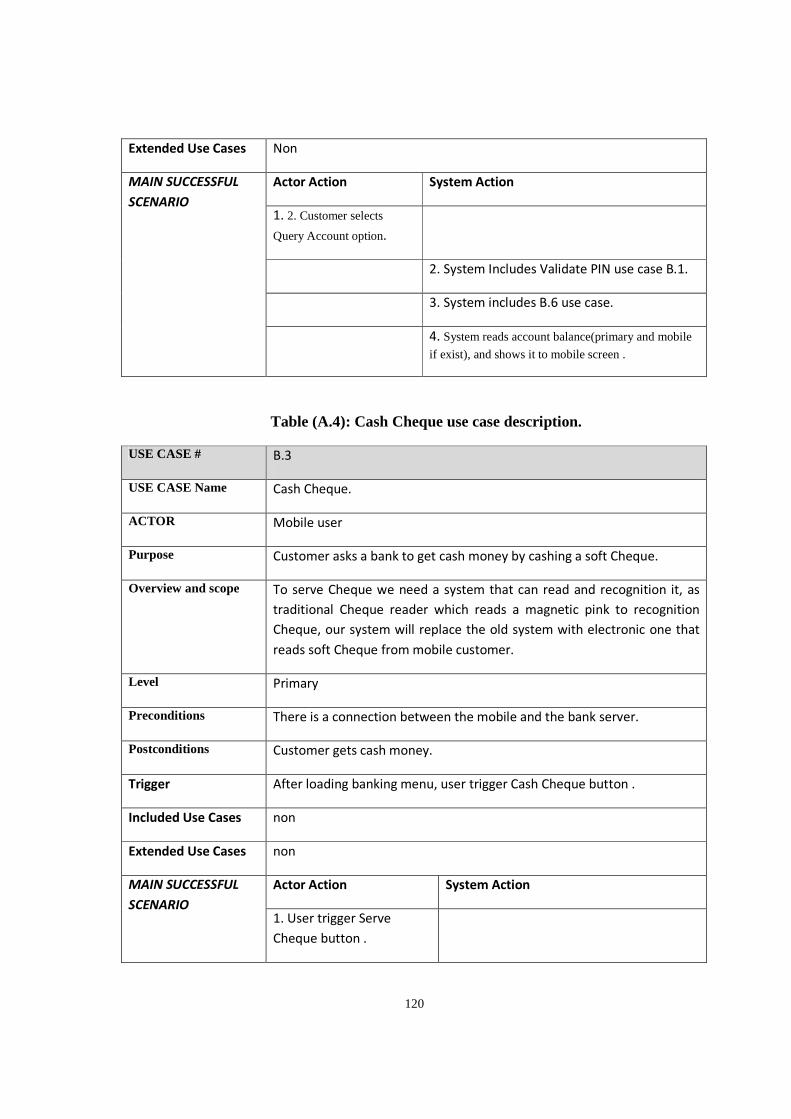
120
Extended Use Cases Non
MAIN SUCCESSFUL
SCENARIO
Actor Action System Action
1. 2. Customer selects
Query Account option.
2. System Includes Validate PIN use case B.1.
3. System includes B.6 use case.
4. System reads account balance(primary and mobile
if exist), and shows it to mobile screen .
Table (A.4): Cash Cheque use case description.
USE CASE # B.3
USE CASE Name Cash Cheque.
ACTOR Mobile user
Purpose Customer asks a bank to get cash money by cashing a soft Cheque.
Overview and scope To serve Cheque we need a system that can read and recognition it, as
traditional Cheque reader which reads a magnetic pink to recognition
Cheque, our system will replace the old system with electronic one that
reads soft Cheque from mobile customer.
Level Primary
Preconditions There is a connection between the mobile and the bank server.
Postconditions Customer gets cash money.
Trigger After loading banking menu, user trigger Cash Cheque button .
Included Use Cases non
Extended Use Cases non
MAIN SUCCESSFUL
SCENARIO
Actor Action System Action
1. User trigger Serve
Cheque button .
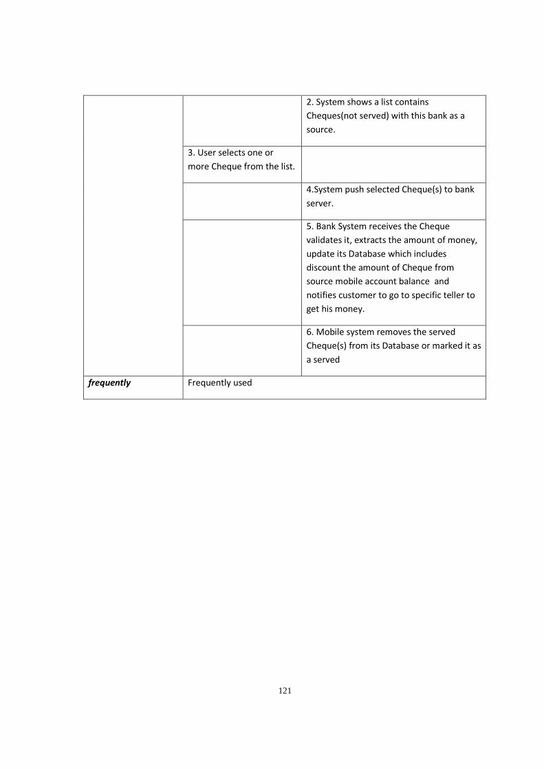
121
2. System shows a list contains
Cheques(not served) with this bank as a
source.
3. User selects one or
more Cheque from the list.
4.System push selected Cheque(s) to bank
server.
5. Bank System receives the Cheque
validates it, extracts the amount of money,
update its Database which includes
discount the amount of Cheque from
source mobile account balance and
notifies customer to go to specific teller to
get his money.
6. Mobile system removes the served
Cheque(s) from its Database or marked it as
a served
frequently Frequently used
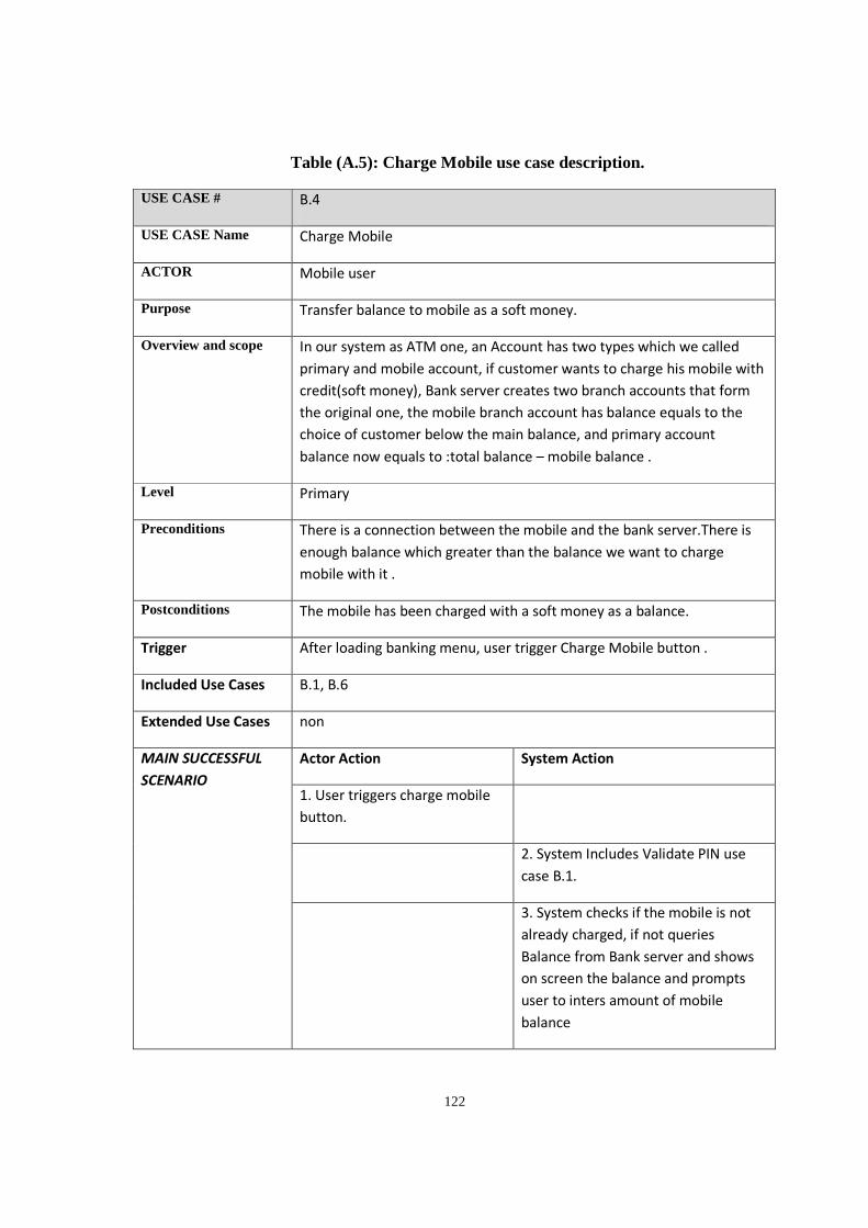
122
Table (A.5): Charge Mobile use case description.
USE CASE # B.4
USE CASE Name Charge Mobile
ACTOR Mobile user
Purpose Transfer balance to mobile as a soft money.
Overview and scope In our system as ATM one, an Account has two types which we called
primary and mobile account, if customer wants to charge his mobile with
credit(soft money), Bank server creates two branch accounts that form
the original one, the mobile branch account has balance equals to the
choice of customer below the main balance, and primary account
balance now equals to :total balance – mobile balance .
Level Primary
Preconditions There is a connection between the mobile and the bank server.There is
enough balance which greater than the balance we want to charge
mobile with it .
Postconditions The mobile has been charged with a soft money as a balance.
Trigger After loading banking menu, user trigger Charge Mobile button .
Included Use Cases B.1, B.6
Extended Use Cases non
MAIN SUCCESSFUL
SCENARIO
Actor Action System Action
1. User triggers charge mobile
button.
2. System Includes Validate PIN use
case B.1.
3. System checks if the mobile is not
already charged, if not queries
Balance from Bank server and shows
on screen the balance and prompts
user to inters amount of mobile
balance
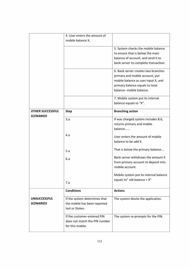
123
4. User enters the amount of
mobile balance X.
5. System checks the mobile balance
to ensure that is below the main
balance of account, and send it to
bank server to complete transaction.
6. Bank server creates two branches
primary and mobile account, put
mobile balance as user input X, and
primary balance equals to total
balance- mobile balance.
7. Mobile system put its internal
balance equals to “X”.
OTHER SUCCESSFUL
SCENARIOS
Step Branching action
3.a
4.a
5.a
6.a
7.a
If was charged system includes B.6,
returns primary and mobile
balance……
User enters the amount of mobile
balance to be add X.
That is below the primary balance….
Bank server withdraws the amount X
from primary account to deposit into
mobile account.
Mobile system put its internal balance
equals to” old balance + X”
UNSUCCESSFUL
SCENARIOS
Conditions Actions
If the system determines that
the mobile has been reported
lost or Stolen.
The system blocks the application.
If the customer-entered PIN
does not match the PIN number
for this mobile.
The system re-prompts for the PIN.
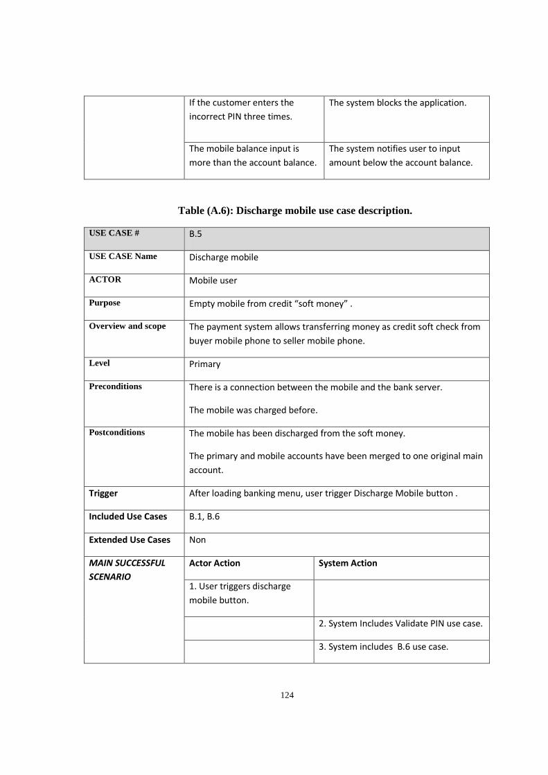
124
If the customer enters the
incorrect PIN three times.
The system blocks the application.
The mobile balance input is
more than the account balance.
The system notifies user to input
amount below the account balance.
Table (A.6): Discharge mobile use case description.
USE CASE # B.5
USE CASE Name Discharge mobile
ACTOR Mobile user
Purpose Empty mobile from credit “soft money” .
Overview and scope The payment system allows transferring money as credit soft check from
buyer mobile phone to seller mobile phone.
Level Primary
Preconditions There is a connection between the mobile and the bank server.
The mobile was charged before.
Postconditions The mobile has been discharged from the soft money.
The primary and mobile accounts have been merged to one original main
account.
Trigger After loading banking menu, user trigger Discharge Mobile button .
Included Use Cases B.1, B.6
Extended Use Cases Non
MAIN SUCCESSFUL
SCENARIO
Actor Action System Action
1. User triggers discharge
mobile button.
2. System Includes Validate PIN use case.
3. System includes B.6 use case.
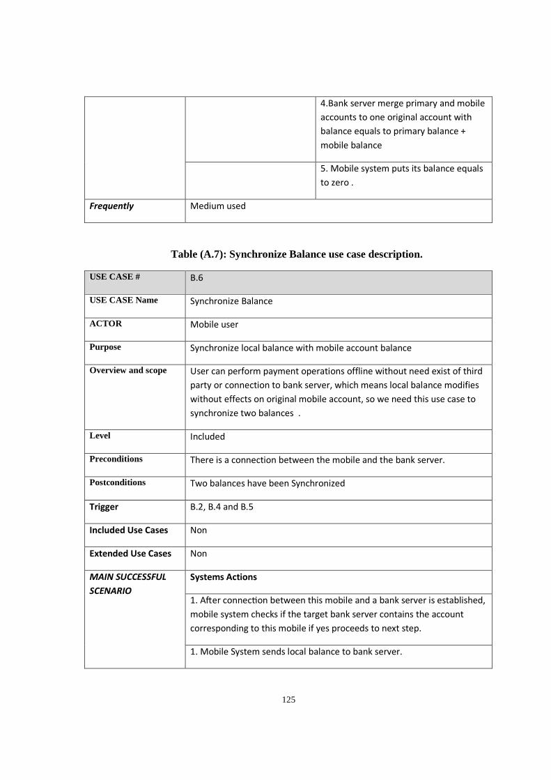
125
4.Bank server merge primary and mobile
accounts to one original account with
balance equals to primary balance +
mobile balance
5. Mobile system puts its balance equals
to zero .
Frequently Medium used
Table (A.7): Synchronize Balance use case description.
USE CASE # B.6
USE CASE Name Synchronize Balance
ACTOR Mobile user
Purpose Synchronize local balance with mobile account balance
Overview and scope User can perform payment operations offline without need exist of third
party or connection to bank server, which means local balance modifies
without effects on original mobile account, so we need this use case to
synchronize two balances .
Level Included
Preconditions There is a connection between the mobile and the bank server.
Postconditions Two balances have been Synchronized
Trigger B.2, B.4 and B.5
Included Use Cases Non
Extended Use Cases Non
MAIN SUCCESSFUL
SCENARIO
Systems Actions
1. A�er connec on between this mobile and a bank server is established,
mobile system checks if the target bank server contains the account
corresponding to this mobile if yes proceeds to next step.
1. Mobile System sends local balance to bank server.
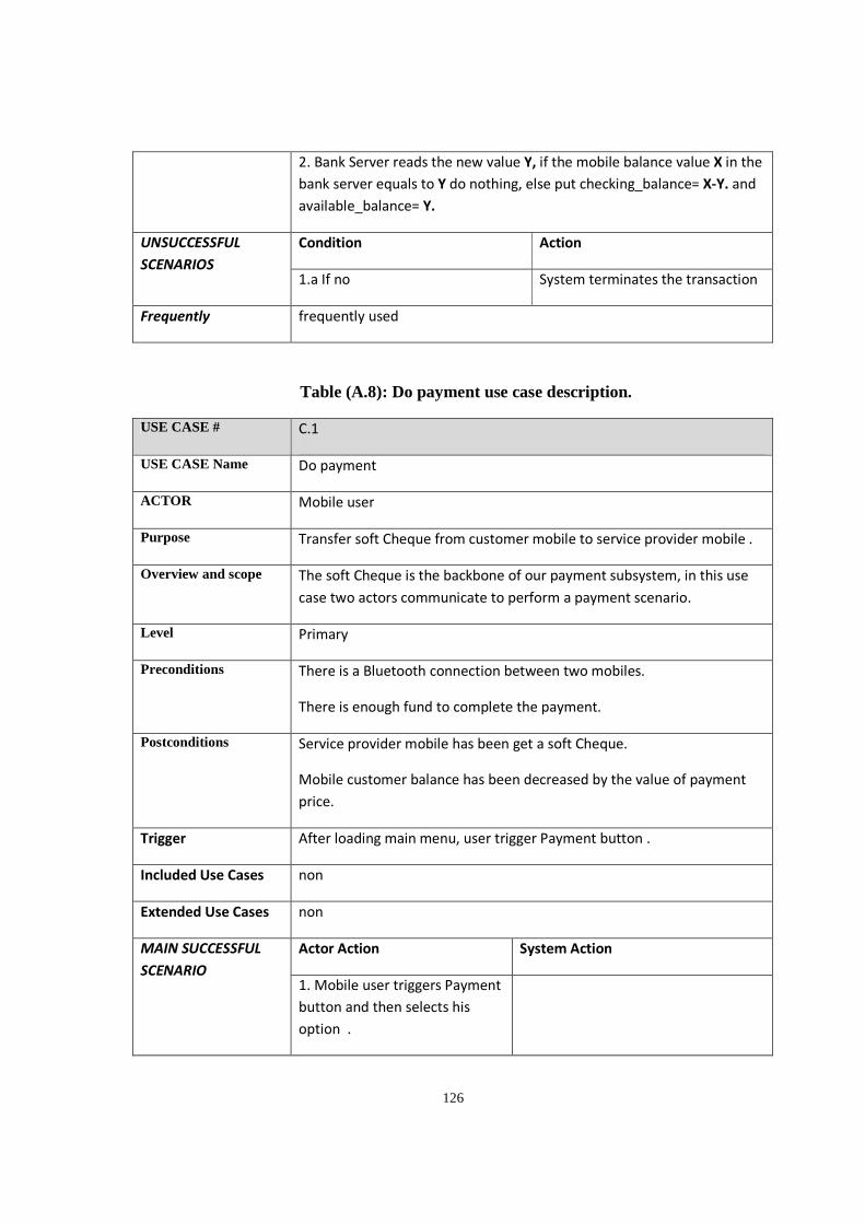
126
2. Bank Server reads the new value Y, if the mobile balance value X in the
bank server equals to Y do nothing, else put checking_balance= X-Y. and
available_balance= Y.
UNSUCCESSFUL
SCENARIOS
Condition Action
1.a If no System terminates the transaction
Frequently frequently used
Table (A.8): Do payment use case description.
USE CASE # C.1
USE CASE Name Do payment
ACTOR Mobile user
Purpose Transfer soft Cheque from customer mobile to service provider mobile .
Overview and scope The soft Cheque is the backbone of our payment subsystem, in this use
case two actors communicate to perform a payment scenario.
Level Primary
Preconditions There is a Bluetooth connection between two mobiles.
There is enough fund to complete the payment.
Postconditions Service provider mobile has been get a soft Cheque.
Mobile customer balance has been decreased by the value of payment
price.
Trigger After loading main menu, user trigger Payment button .
Included Use Cases non
Extended Use Cases non
MAIN SUCCESSFUL
SCENARIO
Actor Action System Action
1. Mobile user triggers Payment
button and then selects his
option .
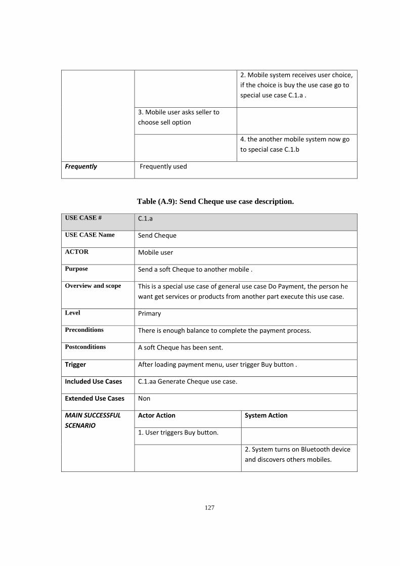
127
2. Mobile system receives user choice,
if the choice is buy the use case go to
special use case C.1.a .
3. Mobile user asks seller to
choose sell option
4. the another mobile system now go
to special case C.1.b
Frequently Frequently used
Table (A.9): Send Cheque use case description.
USE CASE # C.1.a
USE CASE Name Send Cheque
ACTOR Mobile user
Purpose Send a soft Cheque to another mobile .
Overview and scope This is a special use case of general use case Do Payment, the person he
want get services or products from another part execute this use case.
Level Primary
Preconditions There is enough balance to complete the payment process.
Postconditions A soft Cheque has been sent.
Trigger After loading payment menu, user trigger Buy button .
Included Use Cases C.1.aa Generate Cheque use case.
Extended Use Cases Non
MAIN SUCCESSFUL
SCENARIO
Actor Action System Action
1. User triggers Buy bu$on.
2. System turns on Bluetooth device
and discovers others mobiles.
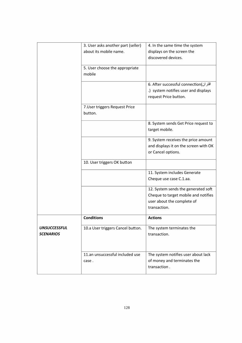
128
3. User asks another part (seller)
about its mobile name.
4. In the same me the system
displays on the screen the
discovered devices.
5. User choose the appropriate
mobile
6. A�er successful connec on(اقتران
.) system notifies user and displays
request Price button.
7.User triggers Request Price
button.
8. System sends Get Price request to
target mobile.
9. System receives the price amount
and displays it on the screen with OK
or Cancel options.
10. User triggers OK bu$on
11. System includes Generate
Cheque use case C.1.aa.
12. System sends the generated so�
Cheque to target mobile and notifies
user about the complete of
transaction.
UNSUCCESSFUL
SCENARIOS
Conditions Actions
10.a User triggers Cancel bu$on. The system terminates the
transaction.
11.an unsuccessful included use
case .
The system notifies user about lack
of money and terminates the
transaction .
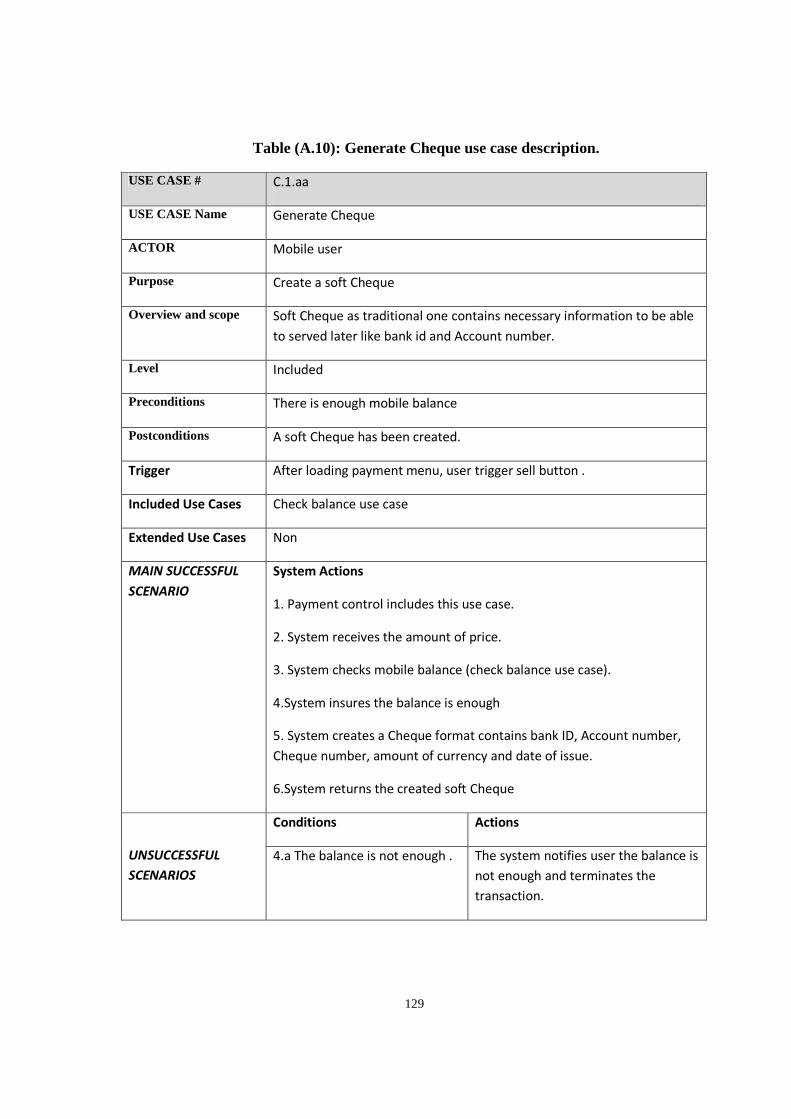
129
Table (A.10): Generate Cheque use case description.
USE CASE # C.1.aa
USE CASE Name Generate Cheque
ACTOR Mobile user
Purpose Create a soft Cheque
Overview and scope Soft Cheque as traditional one contains necessary information to be able
to served later like bank id and Account number.
Level Included
Preconditions There is enough mobile balance
Postconditions A soft Cheque has been created.
Trigger After loading payment menu, user trigger sell button .
Included Use Cases Check balance use case
Extended Use Cases Non
MAIN SUCCESSFUL
SCENARIO
System Actions
1. Payment control includes this use case.
2. System receives the amount of price.
3. System checks mobile balance (check balance use case).
4.System insures the balance is enough
5. System creates a Cheque format contains bank ID, Account number,
Cheque number, amount of currency and date of issue.
6.System returns the created so� Cheque
UNSUCCESSFUL
SCENARIOS
Conditions Actions
4.a The balance is not enough . The system notifies user the balance is
not enough and terminates the
transaction.
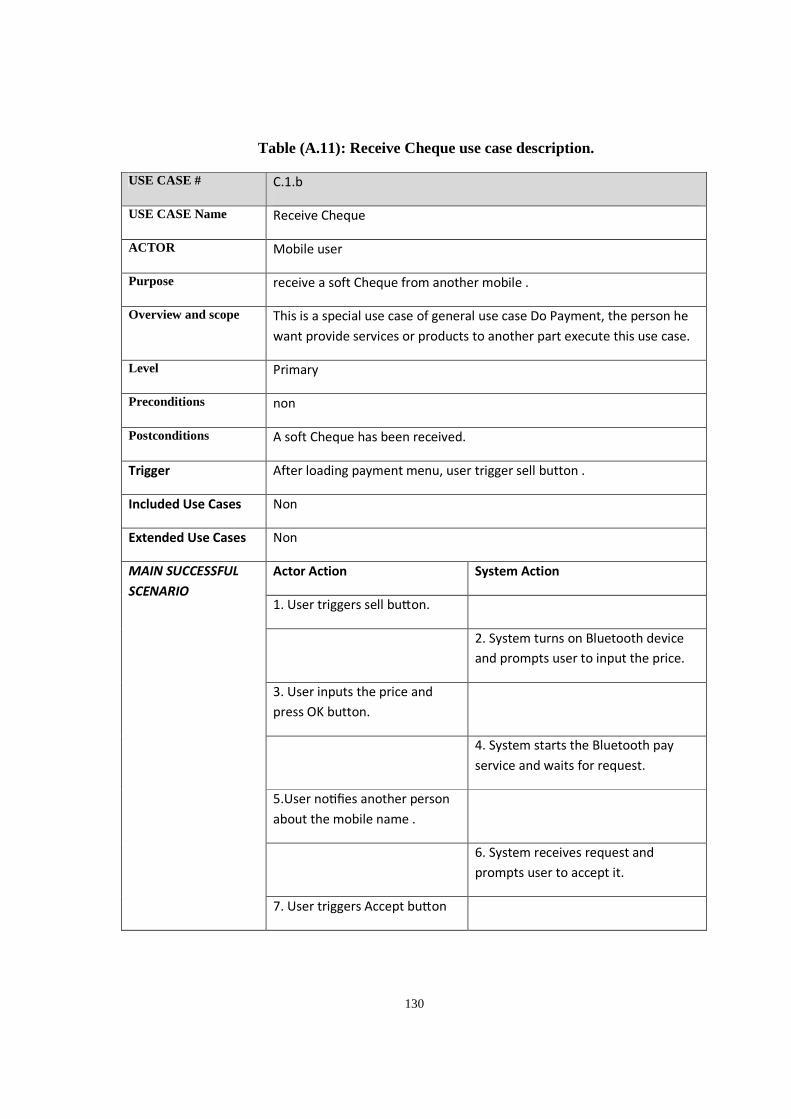
130
Table (A.11): Receive Cheque use case description.
USE CASE # C.1.b
USE CASE Name Receive Cheque
ACTOR Mobile user
Purpose receive a soft Cheque from another mobile .
Overview and scope This is a special use case of general use case Do Payment, the person he
want provide services or products to another part execute this use case.
Level Primary
Preconditions non
Postconditions A soft Cheque has been received.
Trigger After loading payment menu, user trigger sell button .
Included Use Cases Non
Extended Use Cases Non
MAIN SUCCESSFUL
SCENARIO
Actor Action System Action
1. User triggers sell bu$on.
2. System turns on Bluetooth device
and prompts user to input the price.
3. User inputs the price and
press OK button.
4. System starts the Bluetooth pay
service and waits for request.
5.User no fies another person
about the mobile name .
6. System receives request and
prompts user to accept it.
7. User triggers Accept bu$on
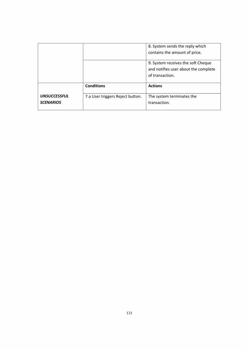
131
8. System sends the reply which
contains the amount of price.
9. System receives the so� Cheque
and notifies user about the complete
of transaction.
UNSUCCESSFUL
SCENARIOS
Conditions Actions
7.a User triggers Reject bu$on. The system terminates the
transaction.


![[Commercial Banking Assignment] Non-Cash Payment in Vietnam](https://img.pdfslide.us/doc/110x75/547f60e6b37959582b8b5846/commercial-banking-assignment-non-cash-payment-in-vietnam.jpg)