Embed Size (px)
Citation preview

Page 1 of 203
Haile Selassie Avenue P. O. Box 60000 Nairobi Kenya Telephone 2860000 Telex 22324
Fax 310604/340192
TENDER DOCUMENT
TENDER FOR SUPPLY, DELIVERY, INSTALLATION, TESTING, AND COMMISSIONING OF PASSENGER LIFTS AND ASSOCIATED WORKS AT KENYA SCHOOL OF MONETARY STUDIES
TENDER NO. CBK/65/2018-2019
CLOSING DATE: 25TH FEBRUARY, 2019 AT 10.30 A.M
BANKI KUU YA KENYA
CENTRAL BANK OF
KENYA

Page 2 of 203
GUIDELINES IN PREPARATION OF BID DOCUMENT In preparing the bid document in response to the tender, bidders are advised to note the following:
1. Section I – Invitation to Tender. This section gives guidelines on how and where to
seek further clarification pertaining to the tender document; the form and amount of
Tender Security required; where and when the tenders should be submitted; and
place where tenders will be opened.
2. Section II – Instruction to Tenderers. This section guides tenderers basically on how
to prepare their bid and how the tendering process will be carried out upto to the
award stage including notification of award to the successful bidder. “Appendix to
Instruction to Tenderers” customizes clauses under Section II. Wherever there is a
conflict between the provisions of the Instructions to Tenderers under Section II and
the provisions of the appendix, the provisions of the appendix prevail.
3. Evaluation Criteria: This gives information on how the tender will be evaluated.
Tenderers should be able to evaluate their bids before submission to determine in
advance whether they meet the requirement of the bid or not. Through the
evaluation criteria bidders will be able to note all the required documents that
should be attached to the bid document.
Checklist of Document Forming the Bid Document:
No. Documents forming part of the bid Bidders Response
1 The main sections of the tender document that includes Section I – Invitation to Tender; Section II – Instruction to Tenderers, including Appendix to Instruction to Tenderers; and section III – General Conditions of the Contract, including Special Conditions of Contract. These Sections remain as they are in the tender document.
2 Copy of Certificate of Incorporation or Business Registration Certificate
3 Provide copy of the company’s current Certificate of Tax Compliance issued by Kenya Revenue Authority (KRA) valid at least up to the tender closing date.
4 Provide a copy of registration in Electrical Engineering Services – Lift Hoist Contractor by National Construction Authority – class NCA5 and above.
5 A Tender Security of Kshs. 100,000.00 is required for this tender with validity period of at least 150 days from the date of tender opening.
6 Dully filled and signed Confidential Business Questionnaire in the form or format provided in the tender document
7 Certified audited accounts for the last two financial years (2016 and 2017)
8 Provide documentary evidence of the proposed lifts’ compliance (certificate

Page 3 of 203
of compliance) with European standards for passenger/goods lifts
9 To provide Manufacturer’s or Master Distributor’s letter of authorization confirming the bidder as dealer/vendor in the region for the proposed type of lifts.
10 Financial proposal containing priced schedules.
11 Duly filled and signed Form of Tender in the format provided in the tender document
12 Copy of Company profile. This should include testimonials of technical personnel, list of similar contracts done previously with supporting documents e.g. LPOs and Contracts.
13 Bidders are requested to attend a Pre-Bid Meeting on the 13th February
2019 at 11.00am Local time at Kenya School of Monetary Studies
14 Provide ALL ITEMS detailed in T1 – T6
15 Only one set of tender document (original) shall be submitted
16 Bid document to be serialized/paginated on all pages and bound

Page 4 of 203
SECTION 1: INVITATION FOR TENDER 1.1 The Central Bank of Kenya invites sealed tender for Supply, Delivery,
Installation and Commissioning of Passenger Lifts and associated works at Kenya School of Monetary Studies.
1.2 Further information as pertains to this tender may be obtained during
working hours (Monday to Friday) between 9:00 am and 5:00 pm using the following address: Ag. Director, General Services Department, Central Bank of Kenya, Haile Selassie Avenue, Nairobi, Tel: +254 20 2861000/2860000, Email: [email protected]
1.3 A complete set of tender document containing detailed information may be
obtained at no cost from Central Bank of Kenya website, www.centralbank.go.ke, or Public Procurement Information Portal (PPIP), www.tenders.go.ke. Bidders who download the tender document are advised to sign a tender register at Procurement Division, along Haile Selassie Avenue, General Services Department on 5th Floor CBK building or email their contact address using email: [email protected] before the tender closing date.
1.4 Prices quoted should be inclusive of all taxes and delivery costs and must be
expressed in Kenya shillings and shall remain valid for a period of 120 days from the closing date of the tender.
1.5 Bidders are requested to attend a Pre-Bid Meeting on the 18th February 2019
at 11.00am Local time at Kenya School of Monetary Studies. Register your attendance with Procurement Office at the Kenya School of Monetary Studies.
1.6 A Tender Security of Kshs. 100,000.00 is required for this tender with
validity period of at least 150 days from the date of tender opening. 1.7 Completed Tender Documents in plain sealed envelopes marked with the
tender number and title should be deposited in the Green Tender Box No. 3
located at the main entrance to the CBK Building on Haile Selassie Avenue before 25th February 2019 at 10.30am.
1.9 Tenders will be opened immediately thereafter, i.e. on 25th February 2019 at
10.30am in the presence of the tenderers representatives who may choose to attend the opening at the Central Bank of Kenya Head Office, GSD Conference Room on 5th Floor.
Ag. DIRECTOR, GENERAL SERVICES DEPARTMENT
Page 5 of 203
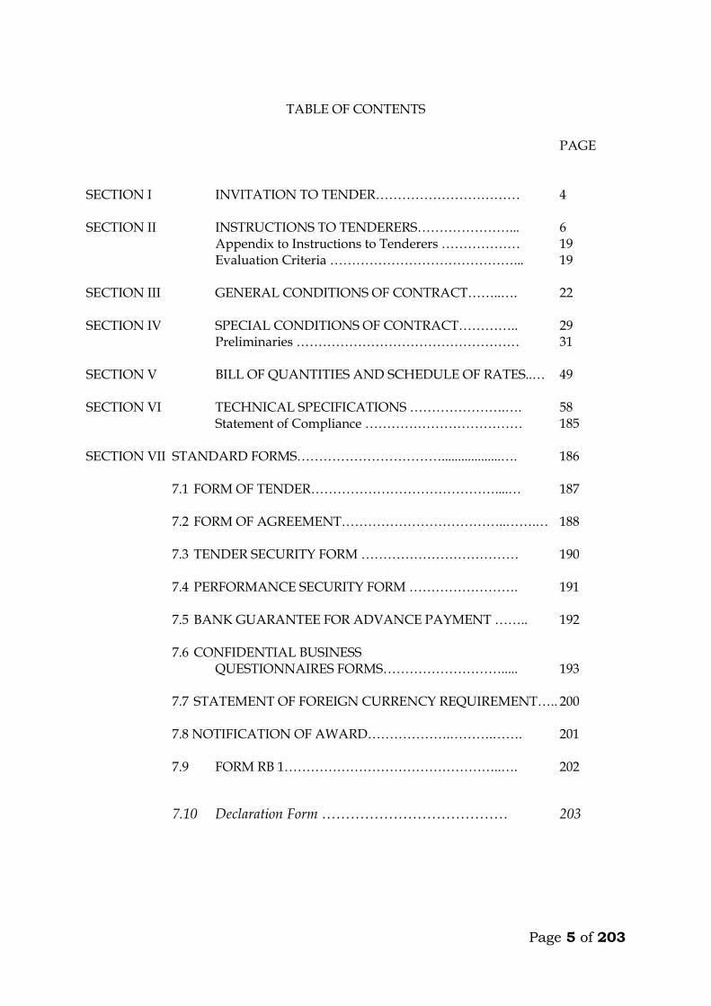
TABLE OF CONTENTS
PAGE SECTION I INVITATION TO TENDER…………………………… 4 SECTION II INSTRUCTIONS TO TENDERERS…………………... 6 Appendix to Instructions to Tenderers ……………… 19 Evaluation Criteria ……………………………………... 19 SECTION III GENERAL CONDITIONS OF CONTRACT……..…. 22 SECTION IV SPECIAL CONDITIONS OF CONTRACT………….. 29 Preliminaries …………………………………………… 31 SECTION V BILL OF QUANTITIES AND SCHEDULE OF RATES..… 49 SECTION VI TECHNICAL SPECIFICATIONS ………………….…. 58 Statement of Compliance ……………………………… 185 SECTION VII STANDARD FORMS……………………………..................…. 186
7.1 FORM OF TENDER……………………………………....… 187
7.2 FORM OF AGREEMENT………………………………..…….… 188
7.3 TENDER SECURITY FORM ……………………………… 190
7.4 PERFORMANCE SECURITY FORM ……………………. 191
7.5 BANK GUARANTEE FOR ADVANCE PAYMENT …….. 192
7.6 CONFIDENTIAL BUSINESS QUESTIONNAIRES FORMS………………………..... 193
7.7 STATEMENT OF FOREIGN CURRENCY REQUIREMENT….. 200 7.8 NOTIFICATION OF AWARD……………….……….……. 201
7.9 FORM RB 1…………………………………………..…. 202
7.10 Declaration Form ………………………………… 203
Page 6 of 203
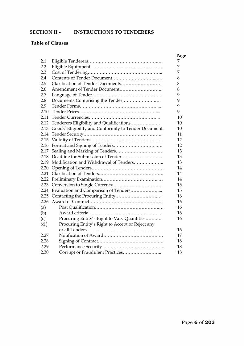
SECTION II - INSTRUCTIONS TO TENDERERS
Table of Clauses
Page
2.1 Eligible Tenderers……………………………………….…. 7 2.2 Eligible Equipment……………………………………..….. 7 2.3 Cost of Tendering………………………………………….. 7 2.4 Contents of Tender Document………………………..….. 8 2.5 Clarification of Tender Documents……………………… 8 2.6 Amendment of Tender Document……………………….. 8 2.7 Language of Tender………………………………………. 9 2.8 Documents Comprising the Tender………………….…. 9 2.9 Tender Forms…………………………………………….... 9 2.10 Tender Prices…………………………………………….... 9 2.11 Tender Currencies………………………………………... 10 2.12 Tenderers Eligibility and Qualifications…………….…. 10 2.13 Goods’ Eligibility and Conformity to Tender Document. 10 2.14 Tender Security…………………………………………….. 11 2.15 Validity of Tenders………………………………………... 12 2.16 Format and Signing of Tenders………………………..…. 12 2.17 Sealing and Marking of Tenders……………………….… 13 2.18 Deadline for Submission of Tender ……………………... 13 2.19 Modification and Withdrawal of Tenders……………….. 13 2.20 Opening of Tenders………………………………………… 14 2.21 Clarification of Tenders……………………………………. 14 2.22 Preliminary Examination………………………………..… 14 2.23 Conversion to Single Currency…………………………… 15 2.24 Evaluation and Comparison of Tenders……………….... 15 2.25 Contacting the Procuring Entity……………………….… 16 2.26 Award of Contract…………………………………………. 16 (a) Post Qualification…………………………………….… 16 (b) Award criteria ……………………………………….… 16 (c) Procuring Entity’s Right to Vary Quantities…….…. 16 (d ) Procuring Entity’s Right to Accept or Reject any
or all Tenders …………………………………………... 16 2.27 Notification of Award……………………………….… 17 2.28 Signing of Contract………………………………….…. 18 2.29 Performance Security ………………………………….. 18 2.30 Corrupt or Fraudulent Practices…………………….. 18

Page 7 of 203
SECTION II – INSTRUCTIONS TO TENDERERS
2.1 Eligible Tenderers
2.1.1 This Invitation for Tenders is open to all tenderers eligible as described in the Appendix to Instructions to Tenderers. Successful tenderers shall complete the supply, install and commissioning of the equipment by the intended completion date specified in the tender documents.
2.1.2 The procuring entity’s employees, committee members, board members and their relative (spouse and children) are not eligible to participate in the tender unless where specially allowed under the Public Procurement and Asset Disposal Act, 2015.
2.1.3 Tenderers shall provide the qualification information statement that the tenderer
(including all members of a joint venture and subcontractors) is not associated, or have been associated in the past, directly or indirectly, with a firm or any of its affiliates which have been engaged by the Procuring entity to provide consulting services for the preparation of the design, specifications, and other documents to be used for the procurement of the goods under this Invitation for tenders.
2.1.4 Tenderers involved in corrupt or fraudulent practices or debarred from participating
in public procurement shall not be eligible. 2.2 Eligible Equipment
2.2.1 All equipment to be supplied and installed under the contract shall have their origin
in eligible source countries. 2.2.2 For purposes of this clause, “origin” means the place where the equipment(s) are
produced. Goods are produced when, through manufacturing, processing, or substantial and major assembly of components, a commercially-recognized product results that is substantially different in basic characteristics or in purpose or utility from its components
2.2.3 The origin of equipment is distinct from the nationality of the tenderer and shall be
treated thus in the evaluation of the tender. 2.3 Cost of Tendering
2.3.1 The Tenderer shall bear all costs associated with the preparation and
submission of its tender, and the procuring entity, will in no case be
responsible or liable for those costs, regardless of the conduct or outcome of
the tendering process.
Page 8 of 203
2.3.2 The price to be charged for the tender document shall not exceed Ksh 1,000.00
2.3.3 The procuring entity shall allow the tenderer to review the tender document free of charge before purchase.
2.4. Contents of Tender Document 2.4.1 The tender document comprises the documents listed below and addenda issued in
accordance with clause 2.6 of these instructions to tenderers (i) Invitation to Tender (ii) Instructions to Tenderers (iii) General Conditions of Contract (iv) Special Conditions of Contract (v) Schedule of requirements (vi) Technical Specifications (vii) Tender Form and Price Schedules (viii) Tender Security Form (ix) Contract Form (x) Performance Security Form (xi) Bank Guarantee for Advance Payment Form (xii) Manufacturer’s Authorization Form (xiii) Confidential Business Questionnaire Form (xiv) Declaration form
2.4.2 The Tenderer is expected to examine all instructions, forms, terms, and specifications
in the tender documents. Failure to furnish all information required by the tender documents or to submit a tender not substantially responsive to the tender documents in every respect will be at the tenderers risk and may result in the rejection of its tender.
2.5 Clarification of Tender Documents 2.5.1 A prospective tenderer making inquiries of the tender documents may notify the Procuring entity in writing or by post at the entity’s address indicated in the invitation for tenders. The Procuring entity will respond in writing to any request for clarification of the tender documents, which it receives not later than seven (7) days prior to the deadline for the submission of tenders, prescribed by the procuring entity. Written copies of the Procuring entities response (including an explanation of the query but without identifying the source of inquiry) will be sent to all prospective tenderers that have received the tender document. 2.5.2 The procuring entity shall reply to any clarifications sought by the tenderer within 3
days of receiving the request to enable the tenderer to make timely submission of its tender.
2.6 Amendment of Tender Documents 2.6.1 At any time prior to the deadline for submission of tender, the procuring entity, for
any reason, whether at its own initiative or in response to a clarification requested by a prospective tenderer, may modify the tender documents by issuing an addendum.
Page 9 of 203
2.6.2 All prospective tenderers that have obtained the tender documents will be notified of
the amendment in writing or by post and will be binding on them. 2.6.3 In order to allow prospective tenderers reasonable time in which to take the
amendment into account in preparing their tenders, the Procuring entity, at its discretion, may extend the deadline for the submission of tenders.
2.7 Language of Tender 2.7.1 The tender prepared by the tenderer, as well as all correspondence and documents
relating to the tender exchange by the tenderer and the Procuring entity, shall be written in English language, provided that any printed literature furnished by the tenderer may be written in another language provided they are accompanied by an accurate English translation of the relevant passages in which case, for purposes of interpretation of the tender, the English translation shall govern.
2.8 Documents Comprising the Tender 2.8.1 The tender prepared by the tenderers shall comprise the following components.
(a) a Tender Form and a Price Schedule completed in accordance with paragraph 2.9, 2.10 and 2.11 below
(b) documentary evidence established in accordance with paragraph 2.12 that the tenderer is eligible to tender and is qualified to perform the contract if its tender is accepted;
(c) documentary evidence established in accordance with paragraph 2.13 that the goods and ancillary services to be supplied by the tenderer are eligible goods and services and conform to the tender documents; and
(d) tender security furnished in accordance with paragraph 2.14 (e) Confidential Business Questionnaire
2.9 Tender Form 2.9.1 The tenderer shall complete the Form of Tender and the appropriate Price Schedule
furnished in the tender documents, indicating the equipment to be supplied, installed and commissioned and a brief description of the equipment, their country of origin, quantity, and prices.
2.10 Tender Prices 2.10.1 The tenderer shall indicate on the appropriate Price Schedule the unit prices where
applicable and total tender price of the equipment and installation it proposes to supply under the contract.
2.10.2 Prices indicated on the Price Schedule shall be entered separately in the following
manner:
(i) the price of the equipment quoted EXW (ex works, ex factory, ex warehouse, ex showroom, or off-the-shelf, as applicable), including all customs duties and sales and other taxes already paid or payable:

Page 10 of 203
(ii) charges for inland transportation, insurance, and other local costs incidental to delivery of the goods to their final destination; and
(iii) installation charges shall also be indicated separately for each equipment 2.10.3 Prices quoted by the tender shall remain fixed during the Tender’s performance of
the contract. A tender submitted with an adjustable price quotation will be treated as non-responsive and will be rejected, pursuant to paragraph 2.22 unless otherwise agreed by the parties.
2.11 Tender Currencies
2.11.1 Prices shall be quoted in the following currencies: (a) For equipment that the tenderer will supply from within Kenya, the
prices shall be quoted in Kenya Shillings; and (b) For equipment that the tenderer will supply from outside Kenya,
the prices may be quoted in US Dollars or in another freely convertible currency.
(c) Cost of installation and commissioning will be in Kenya Shillings.
2.12 Tenderers Eligibility and Qualifications
2.12.1 Pursuant to paragraph 2.1. the tenderers shall furnish, as part of its
tender, documents establishing the tenderers eligibility to tender and its qualifications to perform the contract if its tender is accepted.
2.12.1 The documentary evidence of the tenderers eligibility to tender shall establish to the
Procuring entity’s satisfaction that the tenderer, at the time of submission of its tender, is from an eligible source country as defined under paragraph 2.1
2.12.2 The documentary evidence of the tenderers qualifications to perform the contract if
its tender is accepted shall establish to the Procuring entity’s satisfaction; (a) that, in the case of a tenderer offering to supply equipment under the contract
which the tenderer did not manufacture or otherwise produce, the tenderer has been duly authorized by the equipment, Manufacturer or producer to supply the equipment
(b) that the tenderer has the financial, technical, and production capability necessary to perform the contract;
(c) that, in the case of a tenderer not doing business within Kenya, the tenderer is or will be (if awarded the contract) represented by an Agent in Kenya equipped, and able to carry out the Tenderer’s maintenance, repair, and spare parts-stocking obligations prescribed in the Conditions of Contract and/or Technical Specifications.
2.13 Goods Eligibility and Conformity to Tender Document 2.13.1 Pursuant paragraph 2.2 of this section, the tenderer shall furnish, as part of its tender
documents establishing the eligibility and conformity to the tender documents of all equipment which the tenderer proposes to supply under the contract
Page 11 of 203
2.13.2 The documentary evidence of the eligibility of the goods shall consist of statement in the Price Schedule of the country of origin of the goods and services offered which shall be confirmed by a certificate of origin issued at the time of shipment.
2.13.3 The documentary evidence of conformity of the equipment to the tender documents
may be in the form of literature, drawings, and data, and shall consist of: a) a detailed description of the essential technical and performance
characteristic of the equipment b) a list giving full particulars, including available source and current prices of
spare parts, special tools, etc., necessary for the proper and continuing functioning of the equipment for a period of two (2) years, following commencement of the use of the equipment by the Procuring entity; and
c) a clause-by-clause commentary on the Procuring entity’s Technical Specifications demonstrating substantial responsiveness of the goods and service to those specifications, or a statement of deviations and exceptions to the provisions of the Technical Specifications.
2.13.4 For purposes of the commentary to be furnished pursuant to paragraph 2.13.3(c )
above, the tenderer shall note that standards for workmanship, material, and equipment, as well as references to brand names or catalogue numbers designated by the Procurement entity in its Technical Specifications, are intended to be descriptive only and not restrictive. The tenderer may substitute alternative standards, brand names, and/or catalogue numbers in its tender, provided that it demonstrates to the Procurement entity’s satisfaction that the substitutions ensure substantial equivalence to those designated in the Technical Specifications.
2.14 Tender Security
2.14.1 The tenderer shall furnish, as part of its tender, a tender security for the amount and form specified in the Appendix to Instructions to Tenderers.
2.14.2 The tender security shall be in the amount not exceeding 2 percent of the tender price.
2.14.3 The tender security is required to protect the Procuring entity against the risk of Tenderer’s conduct which would warrant the security’s forfeiture, pursuant to paragraph 2.14.7
2.14.4 The tender security shall be denominated in Kenya Shillings or in another freely convertible currency, and shall be in the form of
a) Cash b) A bank guarantee c) Such insurance guarantee approved by the Authority d) Letter of credit.
2.14.5 Any tender not secured in accordance with paragraph 2.14.1 and 2.14.3 will be rejected by the Procuring entity as non responsive, pursuant to paragraph 2.22
Page 12 of 203
2.14.6 Unsuccessful Tenderer’s tender security will be discharged or returned as promptly as possible but not later than thirty (30) days after the expiration of the period of tender validity prescribed by the Procuring entity.
2.14.7 The successful Tenderer’s tender security will be discharged upon the tenderer signing the contract, pursuant to paragraph 2.27 and furnishing the performance security, pursuant to paragraph 2.28
2.14.8 The tender security may be forfeited:
a) if a tenderer withdraws its tender during the period of tender validity specified by the procuring entity on the Tender Form; or
b) in the case of a successful tenderer, if the tenderer fails:
i) to sign the contract in accordance with paragraph 2.27 1. or
ii) to furnish performance security in accordance with paragraph 2.28 c) If the tenderer rejects correction of an arithmetic error in the tender.
2.15 Validity of Tenders
2.15.1 Tenderers shall remain valid for 120 days or as specified in the tender documents after date of tender opening prescribed by the Procuring entity, pursuant to paragraph 2.20. A tender valid for a shorter period shall be rejected by the Procuring entity as non responsive.
2.15.2 In exceptional circumstances, the Procuring entity may solicit the Tenderer’s consent to an extension of the period of validity. The request and the responses thereto shall be made in writing. The tender security provided under paragraph 2.14 shall also be suitably extended. A tenderer may refuse the request without forfeiting its tender security. A tenderer granting the request will not be required nor permitted to modify its tender.
2.16 Format and Signing of Tender 2.16.1 The Procuring entity shall prepare two copies of the tender, clearly marking each
“ORIGINAL TENDER” and “COPY OF TENDER,” as appropriate. In the event of any discrepancy between them, the original shall govern.
2.16.2 The original and all copies of the tender shall be typed or written in indelible ink and
shall be signed by the tenderer or a person or persons duly authorized to bind the tenderer to the contract. All pages of the tender, except for unamended printed literature, shall be initialed by the person or persons signing the tender.
2.16.3 The tender shall have no interlineations, erasures, or overwriting except as necessary
to correct errors made by the tenderer, in which case such corrections shall be initialed by the person or persons signing the tender.
Page 13 of 203
2.17 Sealing and Marking of Tenders 2.17.1 The Tenderer shall seal the original and each copy of the tender in separate
envelopes, duly marking the envelopes as “ORIGINAL” and “COPY.” The envelopes shall then be sealed in an outer envelope.
2.17.2 The inner and outer envelopes shall:
(a) be addressed to the Procuring entity at the address given on he Invitation to Tender. (b) bear the tender number and name in the Invitation to Tender and the words “DO NOT OPEN BEFORE (day, date at time of closing)
2.17.3 The inner envelopes shall also indicate the name and address of the tenderer to
enable the tender to be returned unopened in case it is declared “late”. 2.17.4 If the outer envelope is not sealed and marked as required by paragraph 2.17.2, the
Procuring entity will assume no responsibility for the tender’s misplacement or premature opening.
2.18 Deadline for Submission of Tenders
2.18.1 Tenders must be received by the Procuring entity at the address specified under paragraph 2.17.2 not later than (the time and date specified).
2.18.2 The Procuring entity may, at its discretion, extend this deadline for the submission of tenders by amending the tender documents in accordance with paragraph 2.6, in which case all rights and obligations of the Procuring entity and candidates previously subject to the deadline will therefore be subject to the deadline as extended
2.18.3 Bulky tenders which will not fit in the tender box shall be received by the procuring
entity as provided for in the Appendix.
2.19 Modification and Withdrawal of Tenders
2.19.1 The tenderer may modify or withdraw its tender after the tender’s submission, provided that written notice of the modification, including substitution or withdrawal of the tenders, is received by the Procuring entity prior to the deadline prescribed for submission of tenders.
2.19.2 The Tenderer’s modification or withdrawal notice shall be prepared, sealed, marked, and dispatched in accordance with the provisions of paragraph 2.17. A withdrawal notice may also be sent by cable, telex but followed by a signed confirmation copy, postmarked not later than the deadline for submission of tenders.
Page 14 of 203
2.19.3 No tender may be modified after the deadline for submission of tenders. 2.19.4 No tender may be withdrawn in the interval between the deadline for submission of
tenders and the expiration of the period of tender validity specified by the tenderer on the Tender Form. Withdrawal of a tender during this interval may result in the Tenderer’s forfeiture of its tender security, pursuant to paragraph 2.14.7
2.20 Opening of Tenders 2.20.1 The Procuring entity will open all tenders in the presence of tenderers’
representatives who choose to attend, at (the time, and the date) and in the following location.(address of the procuring entity) The tenderers’ representatives who are present shall sign a tender opening register evidencing their attendance.
2.20.2 The tenderers’ names, tender modifications or withdrawals, tender prices, discounts and the presence or absence of requisite tender security and such other details as the Procuring entity, at its discretion, may consider appropriate, will be announced at the opening.
2.20.3 The Procuring entity will prepare minutes of the tender opening. 2.21 Clarification of Tenders
2.21.1 To assist in the examination, evaluation and comparison of tenders the Procuring entity may, at its discretion, ask the tenderer for a clarification of its tender. The request for clarification and the response shall be in writing, and no change in the prices or substance of the tender shall be sought, offered, or permitted.
2.21.2 Any effort by the tenderer to influence the Procuring entity in the Procuring entity’s tender evaluation, tender comparison or contract award decisions may result in the rejection of the tenderers’ tender.
2.22 Preliminary Examination and Responsiveness 2.22.1 The Procuring entity will examine the tenders to determine whether they are
complete, whether any computational errors have been made, whether required sureties have been furnished, whether the documents have been properly signed, and whether the tenders are generally in order.
2.22.2 Arithmetical errors will be rectified on the following basis. If there is a discrepancy
between the unit price and the total price that is obtained by multiplying the unit price and quantity, the unit price shall prevail, and the total price shall be corrected. If the candidate does not accept the correction of the errors, its tender will be rejected, and its tender security may be forfeited. If there is a discrepancy between words and figures the amount in words will prevail
Page 15 of 203
2.22.3 The Procuring entity may waive any minor informality or non-conformity or irregularity in a tender which does not constitute a material deviation, provided such waiver does not prejudice or effect the relative ranking of any tenderer.
2.22.4 Prior to the detailed evaluation, pursuant to paragraph 2.23 the Procuring entity will
determine the substantial responsiveness of each tender to the tender documents. For purposes of these paragraphs, a substantially responsive tender is one, which conforms to all the terms and conditions of the tender documents without material deviations. The Procuring entity’s determination of a tender’s responsiveness is to be based on the contents of the tender itself without recourse to extrinsic evidence.
2.22.5 If a tender is not substantially responsive, it will be rejected by the Procuring entity
and may not subsequently be made responsive by the tenderer by correction of the non conformity.
2.23 Conversion to Single Currency 2.23.1 Where other currencies are used, the Procuring Entity will convert those currencies
to Kenya Shillings using the selling exchange rate on the date of tender closing provided by the Central Bank of Kenya.
2.24 Evaluation and Comparison of Tenders
2.24.1 The Procuring entity will evaluate and compare the tenders which have been determined to be substantially responsive, pursuant to paragraph 2.22
2.24.2 The Procuring entity’s evaluation of a tender will exclude and not take into account (a) in the case of equipment manufactured in Kenya or equipment of foreign
origin already located in Kenya, sales and other similar taxes, which will be payable on the goods if a contract is awarded to the tenderer; and
(b) any allowance for price adjustment during the period of execution of the contract, if provided in the tender.
2.24.3 The comparison shall be of the ex-factory/ex-warehouse/off-the-shelf price of the
goods offered from within Kenya, such price to include all costs, as well as duties and taxes paid or payable on components and raw material incorporated or to be incorporated in the goods.
2.24.4 The Procuring entity’s evaluation of a tender will take into account, in addition to
the tender price and the price of incidental services, the following factors, in the manner and to the extent indicated in paragraph 2.23.5 and in the technical specifications:
(a) delivery and installation schedule offered in the tender; (b) deviations in payment schedule from the specifications in the Special Conditions
of Contract; (c) the cost of components, mandatory spare parts and service; (d) the availability in Kenya of spare parts and after-sales service for the equipment
offered in the tender; 2.24.5 Pursuant to paragraph 2.24.4 the following evaluation methods will be applied
Page 16 of 203
(a) Delivery schedule
(i) The Procuring entity requires that the equipment under the Invitation for Tenders shall be delivered at the time specified in the Schedule of Requirements. Tenders offering deliveries longer than the procuring entity’s required delivery time will be treated as non-responsive and rejected.
(b) Deviation in payment schedule
Tenderers shall state their tender price for the payment of schedule outlined in the special conditions of contract. Tenders will be evaluated on the basis of this base price. Tenderers are, however, permitted to state an alternative payment schedule and indicate the reduction in tender price they wish to offer for such alternative payment schedule. The Procuring entity may consider the alternative payment schedule offered by the selected tenderer.
(c ) Spare parts and after sales service facilities
Tenderers must offer items with service and spare parts back-up. Documentary evidence and locations of such back-up must be given. Where a tenderer offers items without such back-up in the country, he must give a documentary evidence and assurance that he will establish adequate back-up for items supplied.
2.24.6 The tender evaluation committee shall evaluate the tender within 30 days of the
validity period from the date of opening the tender. 2.24.7 Preference where allowed in the evaluation of tenders shall not exceed 15% 2.25 Contacting the Procuring Entity 2.25.1 Subject to paragraph 2.21 no tenderer shall contact the Procuring entity on any
matter related to its tender, from the time of the tender opening to the time the contract is awarded.
2.25.2 Any effort by a tenderer to influence the Procuring entity in its decisions on tender,
evaluation, tender comparison, or contract award may result in the rejection of the Tenderer’s tender.
2.26 Award of Contract (a) Post-Qualification
2.26.1 In the absence of pre-qualification, the Procuring entity will determine to its satisfaction whether the tenderer that is selected as having submitted the lowest evaluated responsive tender is qualified to perform the contract satisfactorily.
2.26.2 The determination will take into account the tenderer financial, technical, and
production capabilities. It will be based upon an examination of the documentary evidence of the tenderers qualifications submitted by the tenderer, pursuant to paragraph 2.12.3 as well as such other information as the Procuring entity deems necessary and appropriate.
Page 17 of 203
2.26.3 An affirmative determination will be a prerequisite for award of the contract to the
tenderer. A negative determination will result in rejection of the Tenderer’s tender, in which event the Procuring entity will proceed to the next lowest evaluated tender to make a similar determination of that Tenderer’s capabilities to perform satisfactorily.
(b) Award Criteria 2.26.4 The Procuring entity will award the contract to the successful tenderer(s) whose
tender has been determined to be substantially responsive and has been determined to be the lowest evaluated tender, provided further that the tenderer is determined to be qualified to perform the contract satisfactorily.
2.26.5 To qualify for contract awards, the tenderer shall have the following:
a) Necessary qualifications, capability experience, services, equipment and facilities to provide what is being procured.
b) Legal capacity to enter into a contract for procurement c) Shall not be insolvent, in receivership, bankrupt or in the process of
being wound up and is not the subject of legal proceedings relating to the foregoing.
d) Shall not be debarred from participating in public procurement. (c) Procuring Entity’s Right to Accept or Reject Any or All Tenders 2.26.6 The Procuring entity reserves the right to accept or reject any tender, and to annul the tendering process and reject all tenders at any time prior to contract award, without thereby incurring any liability to the affected tenderer or tenderer of the grounds for the procuring entity’s action 2.26.7 The procuring entity may at any time terminate procurement proceedings before
contract award and shall not be liable to any person for the termination 2.26.8 The procuring entity shall give prompt notice of the termination to the tenderers and
on request give its reasons for termination within 14 days of receiving the request from any tenderer.
2.26.9 A tenderer who gives false information in the tender document about is qualification
or who refuses to enter into a contract after notification of contract award shall be considered for debarment from participating in future public procurement.
2.27 Notification of Award
2.27.1 Prior to the expiration of the period of tender validity, the Procuring entity will notify the successful tenderer in writing that its tender has been accepted.
2.27.2 The notification of award will signify the formation of the Contract but will have to wait until the contract is finally signed by both parties. Simultaneous other tenderers shall be notified that their tenders have not been successful.
Page 18 of 203
2.27.3 Upon the successful Tenderer’s furnishing of the performance security pursuant to paragraph 2.29, the Procuring entity will simultaneously inform the other tenderers that this tenderers have not been successful
2.28 Signing of Contract
2.28.1 At the same time as the Procuring entity notifies the successful tenderer that its tender has been accepted, the procuring entity will simultaneously inform the other tenderers that their tenders have not been successful.
2.28.2 Within fourteen (14) days of receipt of the Contract Form, the successful tenderer shall sign and date the contract and return it to the Procuring entity.
2.28.3 The parties to the contract shall have it signed within 30 days from the date of
notification of contract award unless there is an administrative review request. 2.29 Performance Security
2.29.1 Within Thirty (30) days of the receipt of notification of award from the Procuring entity, the successful tenderer shall furnish the performance security in accordance with the Conditions of Contract, in the Performance Security Form provided in the tender documents, or in another form acceptable to the Procuring entity.
2.29.2 Failure of the successful tenderer to comply with the requirements of paragraph 2.28 or paragraph 2.29 shall constitute sufficient grounds for the annulment of the award and forfeiture of the tender security, in which event the Procuring entity may make the award to the next lowest evaluated Candidate or call for new tenders.
2.30 Corrupt or Fraudulent Practices 2.30.1 The procuring entity requires that tenderers observe the highest standard of ethics
during the procurement process and execution of contracts. A tenderer shall sign a declaration that he has and will not be involved in corrupt or fraudulent practices.
2.30.2 The Procuring entity will reject a proposal for award if it determines that the tenderer recommended for award has engaged in corrupt or fraudulent practices in competing for the contract in question.
2.30.3 Further a tenderer who is found to have indulged in corrupt or fraudulent practices risks being debarred from participating in public Procurement in Kenya.
Page 19 of 203
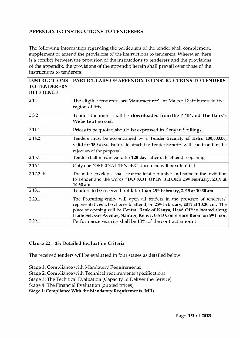
APPENDIX TO INSTRUCTIONS TO TENDERERS
The following information regarding the particulars of the tender shall complement, supplement or amend the provisions of the instructions to tenderers. Wherever there is a conflict between the provision of the instructions to tenderers and the provisions of the appendix, the provisions of the appendix herein shall prevail over those of the instructions to tenderers.
INSTRUCTIONS TO TENDERERS REFERENCE
PARTICULARS OF APPENDIX TO INSTRUCTIONS TO TENDERS
2.1.1 The eligible tenderers are Manufacturer’s or Master Distributors in the region of lifts.
2.3.2 Tender document shall be downloaded from the PPIP and The Bank’s Website at no cost
2.11.1 Prices to be quoted should be expressed in Kenyan Shillings.
2.14.2 Tenders must be accompanied by a Tender Security of Kshs. 100,000.00,
valid for 150 days. Failure to attach the Tender Security will lead to automatic
rejection of the proposal.
2.15.1 Tender shall remain valid for 120 days after date of tender opening.
2.16.1 Only one “ORIGINAL TENDER” document will be submitted
2.17.2 (b) The outer envelopes shall bear the tender number and name in the Invitation to Tender and the words “DO NOT OPEN BEFORE 25th February, 2019 at 10.30 am
2.18.1 Tenders to be received not later than 25th February, 2019 at 10.30 am
2.20.1 The Procuring entity will open all tenders in the presence of tenderers’ representatives who choose to attend, on 25th February, 2019 at 10.30 am. The place of opening will be Central Bank of Kenya, Head Office located along Haile Selassie Avenue, Nairobi, Kenya, GSD Conference Room on 5th Floor.
2.29.1 Performance security shall be 10% of the contract amount
Clause 22 – 25: Detailed Evaluation Criteria The received tenders will be evaluated in four stages as detailed below: Stage 1: Compliance with Mandatory Requirements; Stage 2: Compliance with Technical requirements specifications. Stage 3: The Technical Evaluation (Capacity to Deliver the Service) Stage 4: The Financial Evaluation (quoted prices) Stage 1: Compliance With the Mandatory Requirements (MR)
Page 20 of 203
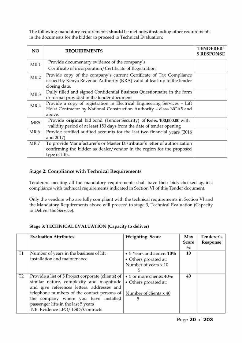
The following mandatory requirements should be met notwithstanding other requirements in the documents for the bidder to proceed to Technical Evaluation:
NO REQUIREMENTS TENDERER’S RESPONSE
MR 1 Provide documentary evidence of the company’s
Certificate of incorporation/Certificate of Registration.
MR 2 Provide copy of the company’s current Certificate of Tax Compliance issued by Kenya Revenue Authority (KRA) valid at least up to the tender closing date.
MR 3 Dully filled and signed Confidential Business Questionnaire in the form or format provided in the tender document
MR 4 Provide a copy of registration in Electrical Engineering Services – Lift Hoist Contractor by National Construction Authority – class NCA5 and above.
MR5 Provide original bid bond (Tender Security) of Kshs. 100,000.00 with validity period of at least 150 days from the date of tender opening
MR 6 Provide certified audited accounts for the last two financial years (2016 and 2017)
MR 7 To provide Manufacturer’s or Master Distributor’s letter of authorization confirming the bidder as dealer/vendor in the region for the proposed type of lifts.
Stage 2: Compliance with Technical Requirements Tenderers meeting all the mandatory requirements shall have their bids checked against compliance with technical requirements indicated in Section VI of this Tender document. Only the vendors who are fully compliant with the technical requirements in Section VI and the Mandatory Requirements above will proceed to stage 3, Technical Evaluation (Capacity to Deliver the Service).
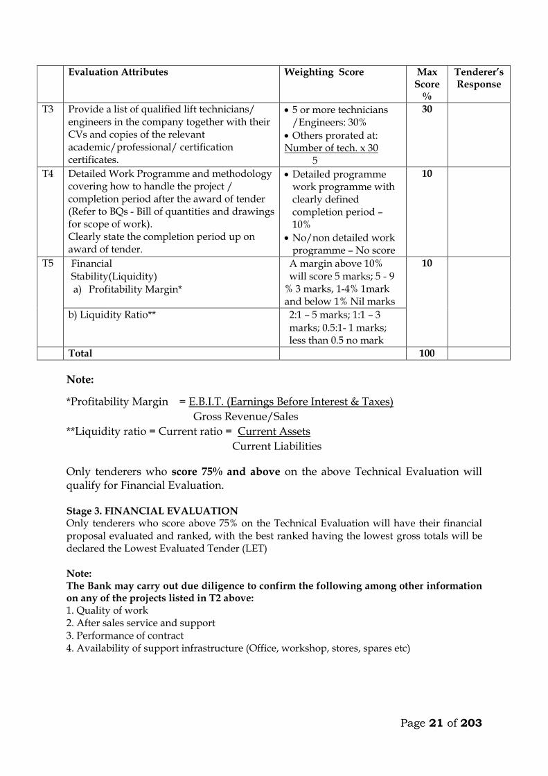
Stage 3: TECHNICAL EVALUATION (Capacity to deliver)
Evaluation Attributes Weighting Score Max Score
%
Tenderer’s Response
T1 Number of years in the business of lift installation and maintenance
5 Years and above: 10%
Others prorated at: Number of years x 10 5
10
T2 Provide a list of 5 Project corporate (clients) of similar nature, complexity and magnitude and give references letters, addresses and telephone numbers of the contact persons of the company where you have installed passenger lifts in the last 5 years NB: Evidence LPO/ LSO/Contracts
5 or more clients: 40%
Others prorated at: Number of clients x 40 5
40
Page 21 of 203
Evaluation Attributes Weighting Score Max Score
%
Tenderer’s Response
T3 Provide a list of qualified lift technicians/ engineers in the company together with their CVs and copies of the relevant academic/professional/ certification certificates.
5 or more technicians /Engineers: 30%
Others prorated at: Number of tech. x 30 5
30
T4 Detailed Work Programme and methodology covering how to handle the project / completion period after the award of tender (Refer to BQs - Bill of quantities and drawings for scope of work). Clearly state the completion period up on award of tender.
Detailed programme work programme with clearly defined completion period – 10%
No/non detailed work programme – No score
10
T5 Financial Stability(Liquidity)
a) Profitability Margin*
A margin above 10% will score 5 marks; 5 - 9
% 3 marks, 1-4% 1mark and below 1% Nil marks
10
b) Liquidity Ratio** 2:1 – 5 marks; 1:1 – 3 marks; 0.5:1- 1 marks; less than 0.5 no mark
Total 100
Note:
*Profitability Margin = E.B.I.T. (Earnings Before Interest & Taxes)
Gross Revenue/Sales
**Liquidity ratio = Current ratio = Current Assets
Current Liabilities
Only tenderers who score 75% and above on the above Technical Evaluation will qualify for Financial Evaluation. Stage 3. FINANCIAL EVALUATION Only tenderers who score above 75% on the Technical Evaluation will have their financial proposal evaluated and ranked, with the best ranked having the lowest gross totals will be declared the Lowest Evaluated Tender (LET) Note: The Bank may carry out due diligence to confirm the following among other information on any of the projects listed in T2 above: 1. Quality of work 2. After sales service and support 3. Performance of contract 4. Availability of support infrastructure (Office, workshop, stores, spares etc)
Page 22 of 203
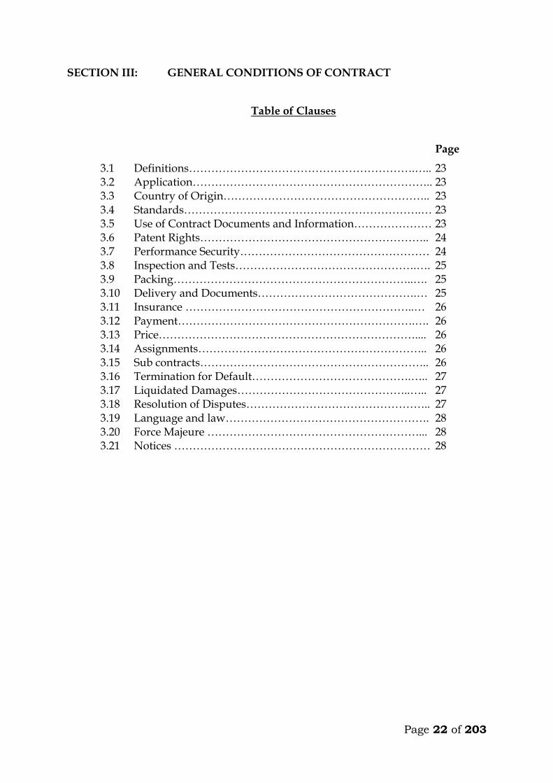
SECTION III: GENERAL CONDITIONS OF CONTRACT
Table of Clauses
Page
3.1 Definitions…………………………………………………….….. 23 3.2 Application……………………………………………………….. 23 3.3 Country of Origin……………………………………………….. 23 3.4 Standards……………………………………………………….… 23 3.5 Use of Contract Documents and Information………………… 23 3.6 Patent Rights…………………………………………………….. 24 3.7 Performance Security…………………………………………… 24 3.8 Inspection and Tests………………………………………….…. 25 3.9 Packing………………………………………………………..…. 25 3.10 Delivery and Documents…………………………………….… 25 3.11 Insurance ……………………………………………………..… 26 3.12 Payment……………………………………………………….…. 26 3.13 Price…………………………………………………………….... 26 3.14 Assignments…………………………………………………….. 26 3.15 Sub contracts…………………………………………………….. 26 3.16 Termination for Default…………………………………….….. 27 3.17 Liquidated Damages………………………………………..….. 27 3.18 Resolution of Disputes………………………………………….. 27 3.19 Language and law………………………………………………. 28 3.20 Force Majeure …………………………………………………... 28 3.21 Notices …………………………………………………………… 28
Page 23 of 203
SECTION III - GENERAL CONDITIONS OF CONTRACT
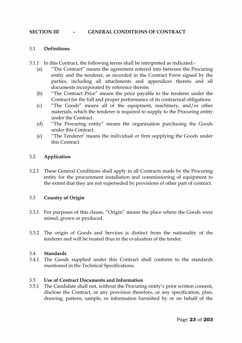
3.1 Definitions
3.1.1 In this Contract, the following terms shall be interpreted as indicated:- (a) “The Contract” means the agreement entered into between the Procuring
entity and the tenderer, as recorded in the Contract Form signed by the parties, including all attachments and appendices thereto and all documents incorporated by reference therein.
(b) “The Contract Price” means the price payable to the tenderer under the Contract for the full and proper performance of its contractual obligations
(c) “The Goods” means all of the equipment, machinery, and/or other materials, which the tenderer is required to supply to the Procuring entity under the Contract.
(d) “The Procuring entity” means the organization purchasing the Goods under this Contract.
(e) “The Tenderer’ means the individual or firm supplying the Goods under this Contract.
3.2 Application
3.2.1 These General Conditions shall apply in all Contracts made by the Procuring entity for the procurement installation and commissioning of equipment to the extent that they are not superseded by provisions of other part of contract.
3.3 Country of Origin
3.3.1 For purposes of this clause, “Origin” means the place where the Goods were mined, grown or produced.
3.3.2 The origin of Goods and Services is distinct from the nationality of the tenderer and will be treated thus in the evaluation of the tender.
3.4 Standards 3.4.1 The Goods supplied under this Contract shall conform to the standards
mentioned in the Technical Specifications.
3.5 Use of Contract Documents and Information 3.5.1 The Candidate shall not, without the Procuring entity’s prior written consent,
disclose the Contract, or any provision therefore, or any specification, plan, drawing, pattern, sample, or information furnished by or on behalf of the

Page 24 of 203
Procuring entity in connection therewith, to any person other than a person employed by the tenderer in the performance of the Contract.
3.5.2 The tenderer shall not, without the Procuring entity’s prior written consent, make use of any document or information enumerated in paragraph 3.5.1 above
3.5.3 Any document, other than the Contract itself, enumerated in paragraph 3.5.1 shall remain the property of the Procuring entity and shall be returned (all copies) to the Procuring entity on completion of the Tenderer’s performance under the Contract if so required by the Procuring entity
3.6 Patent Rights
3.6.1 The tenderer shall indemnify the Procuring entity against all third-party claims of infringement of patent, trademark, or industrial design rights arising from use of the Goods or any part thereof in the Procuring entity’s country
3.7 Performance Security
3.7.1 Within thirty (30) days of receipt of the notification of Contract award, the successful tenderer shall furnish to the Procuring entity the performance security where applicable in the amount specified in Special Conditions of Contract.
3.7.2 The proceeds of the performance security shall be payable to the Procuring entity as compensation for any loss resulting from the Tenderer’s failure to complete its obligations under the Contract.
3.7.3 The performance security shall be denominated in the currency of the contract, or in a freely convertible currency acceptable to the procuring entity and shall be in the form of
a) Cash b) Bank guarantee c) Such insurance guarantee approved by the Authority d) Letter of credit
3.7.4 The performance security will be discharged by the Procuring entity and returned to the Candidate not late than thirty (30) days following the date of completion of the Tenderer’s performance obligations under the Contract, including any warranty obligations, under the Contract
Page 25 of 203
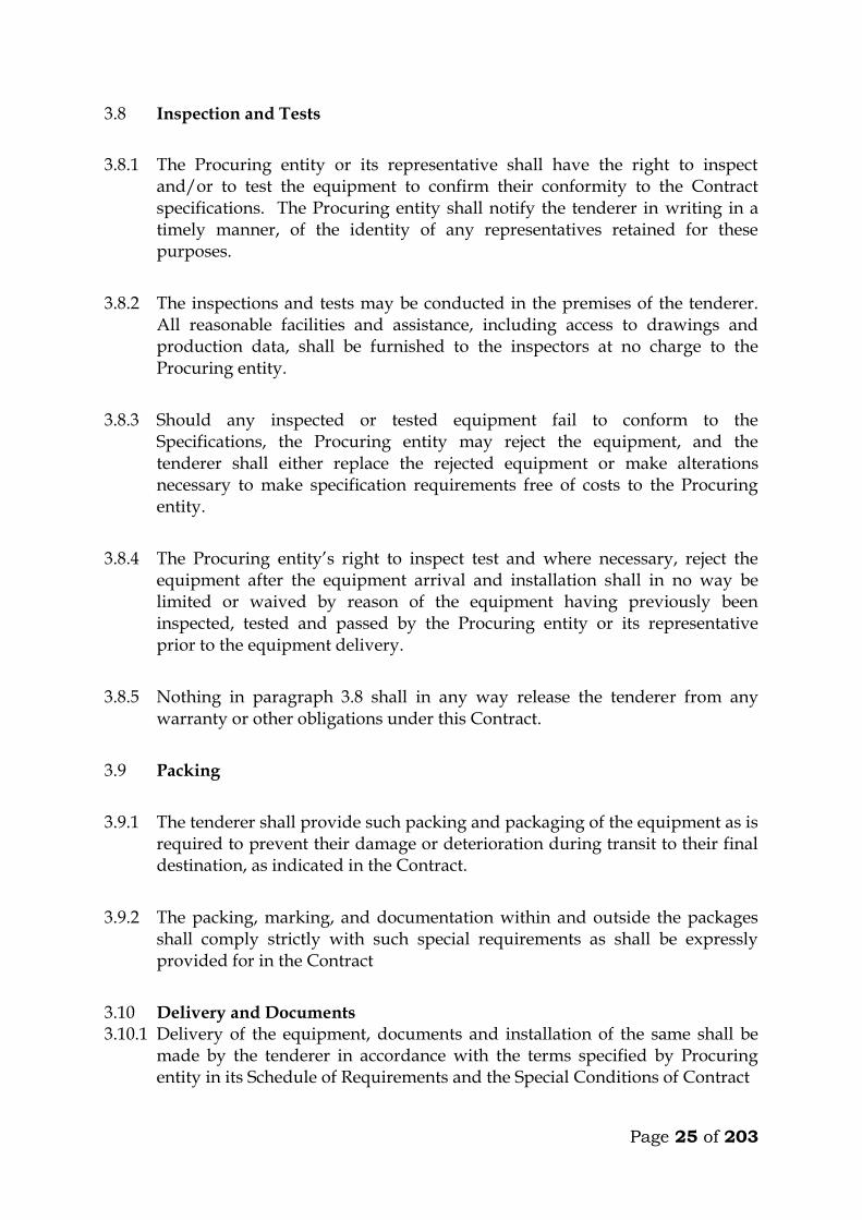
3.8 Inspection and Tests
3.8.1 The Procuring entity or its representative shall have the right to inspect and/or to test the equipment to confirm their conformity to the Contract specifications. The Procuring entity shall notify the tenderer in writing in a timely manner, of the identity of any representatives retained for these purposes.
3.8.2 The inspections and tests may be conducted in the premises of the tenderer. All reasonable facilities and assistance, including access to drawings and production data, shall be furnished to the inspectors at no charge to the Procuring entity.
3.8.3 Should any inspected or tested equipment fail to conform to the Specifications, the Procuring entity may reject the equipment, and the tenderer shall either replace the rejected equipment or make alterations necessary to make specification requirements free of costs to the Procuring entity.
3.8.4 The Procuring entity’s right to inspect test and where necessary, reject the equipment after the equipment arrival and installation shall in no way be limited or waived by reason of the equipment having previously been inspected, tested and passed by the Procuring entity or its representative prior to the equipment delivery.
3.8.5 Nothing in paragraph 3.8 shall in any way release the tenderer from any warranty or other obligations under this Contract.
3.9 Packing
3.9.1 The tenderer shall provide such packing and packaging of the equipment as is required to prevent their damage or deterioration during transit to their final destination, as indicated in the Contract.
3.9.2 The packing, marking, and documentation within and outside the packages shall comply strictly with such special requirements as shall be expressly provided for in the Contract
3.10 Delivery and Documents 3.10.1 Delivery of the equipment, documents and installation of the same shall be
made by the tenderer in accordance with the terms specified by Procuring entity in its Schedule of Requirements and the Special Conditions of Contract
Page 26 of 203
3.11 Insurance
3.11.1 The equipment supplied under the Contract shall be fully insured against loss or damage incidental to manufacturer or acquisition, transportation, storage, and delivery in the manner specified in the Special conditions of contract.
3.12 Payment
3.12.1 The method and conditions of payment to be made to the tenderer under this Contract shall be specified in Special Conditions of Contract
3.12.2 Payments shall be made promptly by the Procuring entity as specified in the contract
3.13 Prices
3.13.1 Prices charged by the tenderer for equipment delivered and installation performed under the Contract shall not, with the exception of any price adjustments authorized in Special Conditions of Contract, vary from the prices by the tenderer in its tender.
3.13.2 Contract price variations shall not be allowed for contracts not exceeding one year (12 months)
3.13.3 Where contract price variation is allowed, the variation shall not exceed 25% of the original contract price.
3.13.4 Price variation requests shall be processed by the procuring entity within 30 days of receiving the request.
3.14. Assignment
The tenderer shall not assign, in whole or in part, its obligations to perform under this Contract, except with the Procuring entity’s prior written consent
3.15. Subcontracts
3.15.1 The tenderer shall notify the Procuring entity in writing of all subcontracts awarded under this Contract if not already specified in the tender. Such
Page 27 of 203
notification, in the original tender or later, shall not relieve the tenderer from any liability or obligation under the Contract
3.16. Termination for Default
3.16.1 The Procuring entity may, without prejudice to any other remedy for breach of Contract, by written notice of default sent to the tenderer, terminate this Contract in whole or in part
(a) if the tenderer fails to deliver any or all of the equipment within the period(s) specified in the Contract, or within any extension thereof granted by the Procuring entity
(b) if the tenderer fails to perform any other obligation(s) under the Contract
(c) if the tenderer, in the judgment of the Procuring entity has engaged in corrupt or fraudulent practices in competing for or in executing the Contract
3.16.2 In the event the Procuring entity terminates the Contract in whole or in part, it may procure, upon such terms and in such manner as it deems appropriate, equipment similar to those undelivered, and the tenderer shall be liable to the Procuring entity for any excess costs for such similar equipment.
3.17. Liquidated Damages
3.17.1 If the tenderer fails to deliver and/or install any or all of the items within the period(s) specified in the contract, the procuring entity shall, without prejudice to its other remedies under the contract, deduct from the contract prices liquidated damages sum equivalent to 0.5% of the delivered price of the delayed items up to a maximum deduction of 10% of the delayed goods. After this the tenderer may consider termination of the contract.
3.18. Resolution of Disputes
3.18.1 The procuring entity and the tenderer shall make every effort to resolve amicably by direct informal negotiation any disagreement or dispute arising between them under or in connection with the contract
3.18.2 If, after thirty (30) days from the commencement of such informal negotiations both parties have been unable to resolve amicably a contract dispute, either party may require that the dispute be referred for resolution to the formal mechanisms specified in the SCC.
Page 28 of 203
3.19. Language and Law
3.19.1 The language of the contract and the law governing the contract shall be English language and the Laws of Kenya respectively unless otherwise specified in the SCC
3.20. Force Majeure
3.20.1 The Tenderer shall not be liable for forfeiture of its performance security or termination for default if and to the extent that it’s delay in performance or other failure to perform its obligations under the Contract is the result of an event of Force Majeure.
3.21 Notices
3.21.1 Any notice given by one party to the other pursuant to this contract shall be sent to other party by post or by fax or Email and confirmed in writing to the other party’s address specified.
3.21.2 A notice shall be effective when delivered or on the notices effective date, whichever is later.
Page 29 of 203
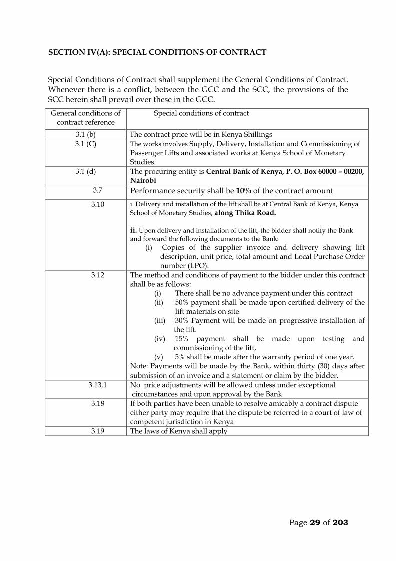
SECTION IV(A): SPECIAL CONDITIONS OF CONTRACT
Special Conditions of Contract shall supplement the General Conditions of Contract. Whenever there is a conflict, between the GCC and the SCC, the provisions of the SCC herein shall prevail over these in the GCC.
General conditions of contract reference
Special conditions of contract
3.1 (b) The contract price will be in Kenya Shillings
3.1 (C) The works involves Supply, Delivery, Installation and Commissioning of Passenger Lifts and associated works at Kenya School of Monetary Studies.
3.1 (d) The procuring entity is Central Bank of Kenya, P. O. Box 60000 – 00200, Nairobi
3.7 Performance security shall be 10% of the contract amount
3.10 i. Delivery and installation of the lift shall be at Central Bank of Kenya, Kenya
School of Monetary Studies, along Thika Road. ii. Upon delivery and installation of the lift, the bidder shall notify the Bank and forward the following documents to the Bank:
(i) Copies of the supplier invoice and delivery showing lift description, unit price, total amount and Local Purchase Order number (LPO).
3.12 The method and conditions of payment to the bidder under this contract shall be as follows:
(i) There shall be no advance payment under this contract (ii) 50% payment shall be made upon certified delivery of the
lift materials on site (iii) 30% Payment will be made on progressive installation of
the lift. (iv) 15% payment shall be made upon testing and
commissioning of the lift, (v) 5% shall be made after the warranty period of one year.
Note: Payments will be made by the Bank, within thirty (30) days after submission of an invoice and a statement or claim by the bidder.
3.13.1 No price adjustments will be allowed unless under exceptional circumstances and upon approval by the Bank
3.18 If both parties have been unable to resolve amicably a contract dispute either party may require that the dispute be referred to a court of law of competent jurisdiction in Kenya
3.19 The laws of Kenya shall apply
Page 30 of 203
B). OTHER CONDITIONS OF THE CONTRACT THE EMPLOYER IS Name: Central Bank of Kenya
Address: P.O. Box 60000-00200, NAIROBI Name of Employer’s Representative: Project Architect, Arprim Consultants Address: P.O. Box 12969-00400, NAIROBI
The name (and identification number) of the Contract is Supply, Delivery, Installation and Commissioning of Passenger Lifts and associated works at Kenya School of Monetary Studies. The Start and Intended Completion Date for the whole of the Works Dates shall be as stated in the Letter of Acceptance The Site Possession Date shall be as stated in the letter of acceptance. The Site is located along Thika Road. The Defects Liability period is 6 Months Amount of Tender Security will be as stated in the letter of invitation
The name and Address of the Employer’s representative for the purposes of submission of tenders is the Project Architect, Arprim Consultants, P. O. Box 12969-00400, Nairobi
Period of final measurement : 3 months after practical completion Liquidated and Ascertained damages: Ksh. 200,000.00
Prime cost sums for which the Contractor desires to tender : NIL Period of honouring certificate : 30 Days
Contract Period : To be advised
Percentage of certified value retained: 5%
Page 31 of 203
C). PRELIMINARIES PART C
1.01 Examination of Tender Documents
The tenderer is required to check the number of pages of this document and should he find any missing or indistinct, he must inform the Engineer at once and have the same rectified. All tenderers shall be deemed to have carefully examined the following: a) Work detailed in the Specification and in the Contract Drawings. b) The Republic of Kenya Document “General Conditions of Contract for
Electrical and Mechanical Works”.
c) Other documents to which reference is made.
He shall also be deemed to have included for any expenditure which may be incurred in conforming with the above items (a), (b), (c) and observe this expense as being attached to the contract placed for the whole or any part of the work. The tenderer shall ensure that all ambiguities, doubts or obscure points of detail, are clarified with the Engineer before submission of his tender, as no claims for alleged deficiencies in the information given shall be considered after this date.
1.02 Discrepancies
The Contractor shall include all work either shown on the Contract Drawings or detailed in the specification. No claim or extra cost shall be considered for works, which has been shown on the drawings or in the specification alone. Should the drawing and the specification appear to conflict, the Contractor shall query the points at the time of tendering and satisfy himself that he has included for the work intended, as no claim for extra payment on this account shall be considered after the contract is awarded.
1.03 Conditions of Contract Agreement
The Contractor shall be required to enter into a Contract with the Client. The Conditions of the Contract between the Client and the Contractor as hereinafter defined shall be the latest edition of the Agreement and Schedule of Conditions of Kenya Association of Building and Civil Engineering Contractors as particularly modified and amended hereinafter.
For the purpose of this contract the Agreement and Schedule of Conditions and any such modifications and amendments shall read and construed together. In any event of discrepancy the modifications and amendments shall prevail.
Page 32 of 203
1.04 Payment
Payment will be made through certificates to the Main Contractor, unless he specifically agrees to forego this right, in which case direct payment can be made to the Contractor. All payments will be less retention as specified in the Main Contract. No payment will become due until materials are delivered to site.
1.05 Definition of Terms Throughout these Contract documents units of measurements, terms and expressions are abbreviated and wherever used hereinafter and in all other documents they shall be interpreted as follows: i) Employer: The term “Employer” shall mean Central Bank of Kenya ii) Architect/Project Manager: The term “Architect” shall mean Arprim
Consultants iii) Electrical Engineer: The term “Electrical Engineer” shall mean Empaq Ltd.
iv) Mechanical Engineer: The term “Mechanical Engineer” shall mean Empaq
Ltd v) Main Contractor: The term “Main Contractor” shall mean the firm or
company appointed to carry out the Building Works and shall include his or their heir, executors, assigns, administrators, successors, and duly appointed representatives.
vi) Contractor: The term “Contractor” shall mean the persons or person, firm or
Company whose tender for this work has been accepted, and who has entered into a contract agreement with the Contractor for the execution of the Contract Works, and shall include his or their heirs, executors, administrators, assigns, successors and duly appointed representatives.
vii) Contract Works: The term “Contract Works” shall mean all or any portion of
the work, materials and articles, whether the same are being manufactured or prepared, which are to be used in the execution of this Contract and whether the same may be on site or not.
viii) Contract Drawings: The term “Contract Drawings” shall mean those
drawings required or referred to herein and forming part of the Bills of Quantities.
ix) Working Drawings: The term “Working Drawings” shall mean those
drawings required to be prepared by the Contractor as hereinafter described.
x) Record Drawings: The term “Record Drawings” shall mean those drawings required to be prepared by the Contractor showing “as installed” and other records for the Contract Works.

Page 33 of 203
xi) Abbreviations:
CM shall mean Cubic Metre
SM shall mean Square Metre
LM shall mean Linear Metre
LS shall mean Lump Sum
mm shall mean Millimetres No. Shall mean Number
Kg. shall mean Kilogram
BS shall mean. Current standard British Standard Specification published by the British Standard Institution, 2 Park Street, London W1, England “Ditto” shall mean the whole of the preceding description in which it occurs. Where it occurs in description of succeeding item it shall mean the same as in the first description of the series in which it occurs except as qualified in the description concerned. Where it occurs in brackets it shall mean the whole of the preceding description which is contained within the appropriate brackets.
1.06 Site Location
The site of the Contract Works is situated at the Kenya School of Monetary Studies along Thika Road.
The tenderer is recommended to visit the site and shall be deemed to have satisfied himself with regard to access, possible conditions, the risk of injury or damage to property on/or adjacent to the site, and the conditions under which the Contract Works shall have to be carried out and no claims for extras will be considered on account of lack of knowledge in this respect.
1.07 Duration of Contract
The Contractor shall be required to state their duration of Contract. The programme is to be agreed with the Client and the Project Manager.
1.08 Scope of Contract Works
The Contractor shall supply, deliver, unload, hoist, fix, test, commission and hand-over in satisfactory working order the complete installations specified hereinafter and/or as shown on the Contract Drawings attached hereto, including the provision of labour, transport and plant for unloading material and storage, and handling into position and fixing, also the supply of ladders, scaffolding the other mechanical devices to plant, installation, painting, testing, setting to work, the removal from site from time to time of all superfluous material and rubbish caused by the works.
The Contractor shall supply all accessories, whether of items or equipment supplied by the Main Contractor but to be fixed and commissioned under this Contract
1.09 Extent of the Contractor’s Duties
At the commencement of the works, the Contractor shall investigate and report to the Engineer if all materials and equipment to be used in the work and not specified
Page 34 of 203
as supplied by the others are available locally. If these materials and equipment are not available locally, the Contractor shall at this stage place orders for the materials in question and copy the orders to the Engineer. Failure to do so shall in no way relieve the Contractor from supplying the specified materials and equipment in time. Materials supplied by others for installation and/or connection by the Subcontractor shall be carefully examined in the presence of the supplier before installation and connection. Any defects noted shall immediately be reported to the Engineer. The Contractor shall be responsible for verifying all dimensions relative to his work by actual measurements taken on site. The Contractor shall mark accurately on one set of drawings and indicate all alterations and/or modifications carried out to the designed system during the construction period. This information must be made available on site for inspection by the Engineer.
1.10 Execution of the Works
The works shall be carried out strictly in accordance with: a) All relevant Kenya Bureau of Standards Specifications. b) All relevant British Standard Specifications and Codes of Practice
(Hereinafter referred to as B.S. and C.P. respectively).
c) This Specification. d) The Contract Drawings.
e) The Bye-laws of the Local Authority.
f) The Architect’s and/or Engineer’s Instructions.
The Contract Drawings and Specifications to be read and construed together.
1.11 Validity of Tender
The tender shall remain valid for acceptance within 120 days from the final date of submission of the tender, and this has to be confirmed by signing the Tender Bond. The tenderer shall be exempted from this Bond if the tender was previously withdrawn in writing to the Employer before the official opening.
1.12 Firm – Price Contract
Unless specifically stated in the documents or the invitation to tender, this is a firm-price Contract and the Contractor must allow in his tender for the increase in the cost of labour and/or materials during the duration of the contract. No claims will be allowed for increased costs arising from the fluctuations in duties and/or day to day currency fluctuations. The Contractor will be deemed to have allowed in his tender for any increase in the cost of materials which may arise as a result of currency

Page 35 of 203
fluctuation during the contract period. 1.13 Variation
No alteration to the Contract Works shall be carried out until receipt by the Contractor of written instructions from the Employer’s Representative Any variation from the contract price in respect of any extra work, alteration or omission requested or sanctioned by the Architect or Engineer shall be agreed and confirmed in writing at the same time such variations are decided and shall not affect the validity of the Contract. Schedule of Unit Rates shall be used to assess the value of such variations. No allowance shall be made for loss of profit on omitted works. Where the Architect requires additional work to be performed, the Contractor, if he considers it necessary, will give notice within seven (7) days to the Main Contractor of the length of time he (the Contractor) requires over and above that allotted for completion of the Contract. If the Contractor fails to give such notice he will be deemed responsible for the claims arising from the delay occasioned by reason of such extension of time.
1.14 Prime Cost and Provisional Sums
A specialist Contractor may be nominated by the Architect to supply and/or install any equipment covered by the Prime Cost or Provisional Sums contained within the Contract documents. The work covered by Prime Cost and Provisional Sums may or may not be carried out at the discretion of the Architect. The whole or any part of these sums utilized by the Contractor shall be deducted from the value of the Contract price when calculating the final account.
1.15 Bond
The tenderer must submit with his tender the name of one Surety who must be an established Bank only who will be willing to be bound to the Client for an amount equal to 10% of the Contract amount as Clause 31 of the Main Contract.
1.16 Government Legislation and Regulations
The Contractor’s attention is called to the provision of the Factory Act 1972 and subsequent amendments and revisions, and allowance must be made in his tender for compliance therewith, in so far as they are applicable. The Contractor must also make himself acquainted with current legislation and any Government regulations regarding the movement, housing, security and control of labour, labour camps, passes for transport, etc. The Contractor shall allow for providing holidays and transport for work people, and for complying with Legislation, Regulations and Union Agreements.
1.17 Import Duty and Value Added Tax
Page 36 of 203
The Contractor will be required to pay full Import Duty and Value Added Tax on all items of equipment, fittings and plant, whether imported or locally manufactured. The tenderer shall make full allowance in his tender for all such taxes.
1.18 Insurance Company Fees Attention is drawn to the tenderers to allow for all necessary fees, where known, that may be payable in respect of any fees imposed by Insurance Companies or statutory authorities for testing or inspection. No allowance shall be made to the Contractor with respect to fees should these have been omitted by the tenderer due to his negligence in this respect.
1.19 Provision of Services by the Main Contractor
In accordance with Clause 1.08 of this Specification the Main Contractor shall make the following facilities available to the Contractor: a) Attendance on the Contractor and the carrying out of all work affecting the
structure of the building which may be necessary, including all chasing, cutting away and making good brickwork, etc., except that all plugging for fixing, fittings, machinery, fan ducting, etc., and all drilling and tapping of steel work shall be the responsibility of the Contractor. Any purpose made fixing brackets shall not constitute Builder’s Work and shall be provided and installed by the Contractor unless stated hereinafter otherwise.
b) The provision of temporary water, lighting and power: All these services
utilized shall be paid for by the Main Contractor. The Contractor shall, however, allow for additional connections/extensions required for his purposes.
c) Fixing of anchorage and pipe supports in the shuttering, except that all
anchorage shall be supplied by the Contractor who shall also supply the Main Contractor with fully dimensioned drawings detailing the exact locations.
d) i) Provision of scaffolding, cranes, etc. but only in so far as it is required for the
Main Contract Works. It shall be the Contractor’s responsibility to liaise with the Main Contractor to ensure that there is maximum co-operation with other Contractors in the use of scaffolding, cranes, etc.
ii) Any specialist scaffolding, cranes, etc. by the Contractor for his own exclusive use shall be paid for by the Contractor.
1.20 Suppliers
The Contractor shall submit names of any supplier for the materials to be incorporated, to the Engineer for approval. The information regarding the names of the suppliers may be submitted at different times, as may be convenient, but no sources of supply will be changed without prior approval. Each supplier must be willing to admit the Engineer or his representative to his

Page 37 of 203
premises during working hours for the purpose of examining or obtaining samples of the materials in question.
1.21 Samples and Materials Generally
The Contractor shall, when required, provide for approval at no extra cost, samples of all materials to be incorporated in the works. Such samples, when approved, shall be retained by
the Engineer and shall form the standard for all such materials incorporated. 1.22 Administrative Procedure and Contractual Responsibility
Wherever within the Specification it is mentioned or implied that the Contractor shall deal direct with the Employer or Engineer, it shall mean “through the Contractor” who is responsible to the Employer for the whole of the works including the Contract Works.
1.23 Bills of Quantities
The Bills of Quantities have been prepared in accordance with the standard method of measurement of Building Works for East Africa, first Edition, Metric, 1970. All the Quantities are based on the Contract Drawings and are provisional and they shall not be held to gauge or to limit the amount or description of the work to be executed by the Contractor but the value thereof shall be deducted from the Contract Sum and the value of the work ordered by the Engineer and executed thereunder shall be measured and valued by the Engineer in accordance with the conditions of the Contract. All work liable to adjustment under this Contract shall be left uncovered for a reasonable time to allow measurements needed for such adjustment to be taken by the Quantity Surveyor or Engineer. Immediately the work is ready for measuring the Contractor shall give notice to the Quantity Surveyor or Engineer to carry out measurements before covering up. If the Contractor shall make default in these respects he shall, if the Architect so directs, uncover the work to enable the necessary measurements to be taken and afterwards reinstate at his own expense.
1.24 Contractor’s Office in Kenya
The Contractor shall maintain (after first establishing if necessary) in Kenya an office staffed with competent Engineer Manager and such supporting technical and clerical staff as necessary to control and coordinate the execution and completion of the Contract Works. The Engineer Manager and his staff shall be empowered by the Contractor to represent him at meetings and in discussions with the Main Contractor, the Engineer and other parties who may be concerned and any liaison with the Contractor’s Head Office on matters relating to the design, execution and completion of the Contract Works shall be effected through his office in Kenya.
Page 38 of 203
It shall be the Contractor’s responsibility to procure work permits, entry permits, licenses, registration, etc., in respect of all expatriate staff. The Contractor shall prepare a substantial proportion of his Working Drawings at his office in Kenya. No reasons for delays in the preparation or submission for approval or otherwise of such drawings or proposals will be accepted on the grounds that the Contractor’s Head Office is remote from his office in Nairobi or the site of the Contract Works or otherwise.
1.25 Builder’s Work
All chasing, cutting away and making good will be done by the Main Contractor but the Contractor shall mark out in advance and shall be responsible for accuracy of the size and position of all holes and chases required. The Contractor shall drill and plug holes in floors, walls, ceiling and roof for securing services and equipment requiring screw or bolt fixings. Any purpose made fixing brackets shall not constitute builder’s work and shall be provided and installed by the Contractor unless stated hereinafter to the contrary.
1.26 Structural Provision for the Works
Preliminary major structural provision has been made for the Contract Works based on outline information ascertained during the preparation of the Specification. The preliminary major structural provision made will be deemed as adequate unless the Contractor stated otherwise when submitting his tender.
Any major structural provision or alteration to major structural provisions required by the Contractor shall be shown on Working Drawings to be submitted to the Engineer within 30 days of being appointed. No requests for alterations to preliminary major structural provisions will be approved except where they are considered unavoidable by the Engineer. In no case will they be approved if building work is so far advanced as to cause additional costs or delays in the work of the Main Contractor.
1.27 Position of Services, Plant, Equipment, Fittings and Apparatus
The Contract Drawings give a general indication of the intended layout. The position of the equipment and apparatus, and also the exact routes of the ducts, main and distribution pipework shall be confirmed before installation is commenced. The exact siting of appliances, pipework, etc., may vary from that indicated. The routes of services and positions of apparatus shall be determined by the approved dimensions detailed in the Working Drawings or on site by the Engineer in consultation with the Contractor or the Main Contractor. Services throughout the ducts shall be arranged to allow maximum access along the ducts and the services shall be readily accessible for maintenance. Any work, which has to be re-done due to negligence in this respect, shall be the Contractor’s
Page 39 of 203
responsibility. The Contractor shall be deemed to have allowed in his Contract Sum for locating terminal points of services (e.g. lighting, switches, socket outlets, lighting points, control switches, thermostats and other initiating devices, taps, stop cocks) in positions plus or minus 1.2m horizontally and vertically from the locations shown on Contract Drawings. Within these limits no variations in the Contract Sum will be made unless the work has already been executed in accordance with previously approved Working Drawings and with the approval of the Engineer.
1.28 Checking of Work
The Contractor shall satisfy himself to the correctness of the connections he makes to all items of equipment supplied under the Contract agreement and equipment supplied under other contracts before it is put into operation. Details of operation, working pressures, temperatures, voltages, phases, power rating, etc., shall be confirmed to others and confirmation received before the system is first operated.
1.29 Setting to Work and Regulating System
The Contractor shall carry out such tests of the Contract Works as required by British
Standard Specifications, or equal and approved codes as specified hereinafter and as customary.
No testing or commissioning shall be undertaken except in the presence of and to the satisfaction of the Engineer unless otherwise stated by him (Contractor’s own preliminary and proving tests excepted).
It will be deemed that the Contractor has included in the Contract Sum for the costs of all fuel, power, water and the like, for testing and commissioning as required as part of the Contract Works. He shall submit for approval to the Engineer a suitable programme for testing and commissioning. The Engineer and Employer shall be given ample warning in writing, as to the date on which testing and commissioning will take place. The Contractor shall commission the Contract Works and provide attendance during the commissioning of all services, plant and apparatus connected under the Contract Agreement or other Contract Agreements, related to the project. Each system shall be properly balanced, graded and regulated to ensure that correct distribution is achieved and where existing installations are affected, the Contractor shall also regulate these systems to ensure that their performance is maintained. The proving of any system of plant or equipment as to compliance with the Specification shall not be approved by the Engineer, except at his discretion, until tests have been carried out under operating conditions pertaining to the most onerous conditions specified except where the time taken to obtain such conditions is unreasonable or exceeds 12 months after practical completion of the Contract Works.
1.30 Identification of Plant Components
Page 40 of 203
The Contractor shall supply and fix identification labels to all plant, starters, switches and items of control equipment including valves, with white traffolyte or equal labels engraved in red lettering denoting its name, function and section controlled. The labels shall be mounted on equipment and in the most convenient positions. Care shall be taken to ensure the labels can be read without difficulty. This requirement shall apply also to major components of items of control equipment. Details of the lettering of the labels and the method of mounting or supporting shall be forwarded to the Engineer for approval prior to manufacture.
1.31 Contract Drawings
The Contract Drawings when read in conjunction with the text of the Specification have been completed in such detail as was considered necessary to enable competitive tenders to be obtained for the execution and completion of the Contract works.
The Contract Drawings are not intended to be Working Drawings and shall not be used unless exceptionally they are released for this purpose.
1.32 Working Drawings
The Contractor shall prepare such Working Drawings as may be necessary. The Working Drawings shall be complete in such detail not only that the Contract Works can be executed on site but also that the Engineer can approve the Contractor’s proposals, detailed designs and intentions in the execution of the Contract Works. If the Contractor requires any further instructions, details, Contract Drawings or information drawings to enable him to prepare his Working Drawings or proposals, the Contractor shall accept at his own cost, the risk that any work, commenced or which he intends to commence at site may be rejected. The Engineer, in giving his approval to the Working Drawings, will presume that any necessary action has been, or shall be taken by the Contractor to ensure that the installations shown on the Working Drawings have been cleared with the Main Contractor and any other Contractors whose installations and works might be affected. If the Contractor submits his Working Drawings to the Engineer without first liaising and obtaining clearance for his installations from the Main Contractor and other Contractors whose installations and works might be affected, then he shall be liable to pay for any alterations or modification to his own, the Main Contractor’s or other Contractor’s installations and works, which are incurred, notwithstanding any technical or other approval received from the Engineer. Working Drawings to be prepared by the Contractor shall include but not be restricted to the following: a) Any drawings required by the Main Contractor, or Engineer to enable
structural provisions
Page 41 of 203
to be made including Builder’s Working Drawings or Schedules and those for the detailing of holes, fixings, foundations, cables and paperwork ducting below or above ground or in or outside or below buildings.
b) General Arrangement Drawings of all plant, control boards, fittings and
apparatus or any part thereof and of installation layout arrangement of such plant and apparatus.
c) Schematic Layout Drawings of services and of control equipment.
d) Layout Drawings of all embedded and non-embedded paperwork, ducts and
electrical conduits.
e) Complete circuit drawings of the equipment, together with associated circuit description.
f) Such other drawings as are called for in the text of the Specification or
Schedules or as the Engineer may reasonably require.
Three copies of all Working Drawings shall be submitted to the Engineer for approval. One copy of the Working Drawings submitted to the Engineer for approval shall be returned to the Contractor indicating approval or amendment therein. Six copies of the approved Working Drawings shall be given to the Main Contractor by the Contractor for information and distribution to other Contractors carrying out work associated with or in close proximity to or which might be affected by the Contract Works.
Approved Working Drawings shall not be departed from except as may be approved or directed by the Engineer.
Approval by the Engineer of Working Drawings shall neither relieve the Contractor of any of his obligations under the Contract nor relieve him from correcting any errors found subsequently in the Approved Working Drawings or other Working Drawings and in the Contract Works on site or elsewhere associated therewith. The Contractor shall ensure that the Working Drawings are submitted to the Architect for approval at a time not unreasonably close to the date when such approval is required. Late submission of his Working Drawings will not relieve the Contractor of his obligation to complete the Contract Works within the agreed Contract Period and in a manner that would receive the approval of the Architect.
1.33 Record Drawings (As Installed) and Instructions During the execution of the Contract Works the Contractor shall, in a manner approved by the Engineer record on Working or other Drawings at site all information necessary for preparing Record Drawings of the installed Contract Works. Marked-up Working or other Drawings and other documents shall be made available to the Engineer as he may require for inspection and checking.
Page 42 of 203
Record Drawings, may, subject to the approval of the Engineer, include approved Working Drawings adjusted as necessary and certified by the Contractor as a correct record of the installation of the Contract Works. They shall include but not restricted to the following drawings or information: a) Working Drawings amended as necessary but titled “Record Drawings” and
certified as a true record of the “As Installed” Contract Works. Subject to the approval of the Engineer such Working Drawings as may be inappropriate may be omitted.
b) Fully dimensioned drawings of all plant and apparatus
c) General arrangement drawings of equipment, other areas containing plant
forming part of the Contract Works and the like, indicating the accurate size and location of the plant and apparatus suitability cross-referenced to the drawings mentioned in (b) above and hereinafter.
d) Routes, types, sizes and arrangement of all pipework and ductwork including
dates of installation of underground pipework.
e) Relay adjustment charts and manuals.
f) Routes, types, sizes and arrangement of all electric cables, conduits, ducts and wiring including the dates of installation of buried works.
g) System schematic and trunking diagrams showing all salient information
relating to control and instrumentation.
h) Grading Charts.
i) Valve schedules and locations suitability cross-referenced.
j) Wiring and piping diagrams of plant and apparatus.
k) Schematic diagrams of individual plant, apparatus and switch and control boards. These diagrams to include those peculiar to individual plant or apparatus and also those applicable to system operation as a whole.
l) Operating Instruction
Schematic and wiring diagrams shall not be manufacturer’s multipurpose general issue drawings. They shall be prepared specially for the Contract Works and shall contain no spurious or irrelevant information.
Marked-up drawings of the installation of the Contract Works shall be kept to date and completed by the date of practical or section completion. Two copies of the Record Drawings of Contract Works and two sets of the relay adjustment and grading charts and schematic diagrams on stiff backing shall be provided not later than one month later.
Page 43 of 203
The Contractor shall supply for fixing in sub-stations, switch-rooms, boiler houses, plant rooms, pump houses, the office of the Maintenance Engineer and other places, suitable valve and instructions charts, schematic diagrams of instrumentation and of the electrical reticulation as may be requested by the Engineer providing that the charts, diagrams, etc., relate to installations forming part of the Contract Works. All such charts and diagrams shall be of suitable plastic material on a stiff backing and must be approved by the Engineer before final printing.
Notwithstanding the Contractor’s obligations referred to above, if the Contractor fails to produce to the Engineer’s approval, either:-
a) The Marked-up Drawings during the execution of the Contract Works
or
b) The Record Drawings, etc., within one month of the Section or Practical Completion
The Engineer shall have these drawings produced by others. The cost of obtaining the necessary information and preparing such drawings, etc., will be recovered from the Contractor.
1.34 Maintenance Manual
Upon Practical Completion of the Contract Works, the Contractor shall furnish the Engineer four copies of a Maintenance Manual relating to the installation forming part of all of the Contract Works. The manual shall be loose-leaf type, International A4 size with stiff covers and cloth bound. It may be in several volumes and shall be sub-divided into sections, each section covering one Engineering service system. It shall have a ready means of reference and a detailed index. There shall be a separate volume dealing with Air Conditioning and Mechanical Ventilation installation where such installations are included in the Contract Works. The manual shall contain full operating and maintenance instructions for each item of equipment, plant and apparatus set out in a form dealing systematically with each system. It shall include as may be applicable to the Contract Works the following and any other items listed in the text of the Specifications: a) System Description. b) Plant c) Valve Operation d) Switch Operation e) Procedure of Fault Finding f) Emergency Procedures g) Lubrication Requirements h) Maintenance and Servicing Periods and Procedures i) Colour Coding Legend for all Services
j) Schematic and Writing Diagrams of Plant and Apparatus

Page 44 of 203
k) Record Drawings, true to scale, folded to International A4 size l) Lists of Primary and Secondary Spares.
The manual is to be specially prepared for the Contract Works and manufacturer’s standard descriptive literature and plant operating instruction cards will not be accepted for inclusion unless exceptionally approved by the Engineer. The Contractor shall, however, affix such cards, if suitable, adjacent to plant and apparatus. One spare set of all such cards shall be furnished to the Engineer.
1.35 Hand-over
The Contract Works shall be considered complete and the Maintenance and Defects Liability Period shall commence only when the Contract Works and supporting services have been tested, commissioned and operated to the satisfaction of the Engineer and officially approved and accepted by the Employer, provided always that the handing over of the Contract Works shall be coincident with the handing over of the Main Contract Works.
The procedure to be followed will be as follows: a) On the completion of the Contract Works to the satisfaction of the Engineer
and the Employer, the Contractor shall request the Engineer, at site to arrange for handing over.
b) The Engineer shall arrange a Hand-over Meeting or a series thereof, at site.
c) The Contractor shall arrange with the Engineer and Employer for a complete
demonstration of each and every service to be carried out and for instruction to be given to the relevant operation staff and other representatives of the Employer.
d) In the presence of the Employer and the Engineer, Hand-over will take place,
subject to Agreement of the Hand-over Certificates and associated check lists.
1.36 Painting
It will be deemed that the Contractor allowed for all protective and finish painting in the Contract Sum for the Contract Works, including colour coding of service pipework to the approval of the Engineer. Any special requirements are described in the text of the Specifications.
1.37 Spares The Contractor shall supply and deliver such spares suitably protected and boxed to the Engineer’s approval as are called for in the Specifications or in the Price Schedules.
1.38 Testing and Inspection – Manufactured Plant

Page 45 of 203
The Engineer reserves the right to inspect and test or witness of all manufactured plant equipment and materials. The right of the Engineer relating to the inspection, examination and testing of plant during manufacture shall be applicable to Insurance companies and inspection authorities so nominated by the Engineer. The Contractor shall give two week’s notice to the Engineer of his intention to carry out any inspection or tests and the Engineer or his representative shall be entitled to witness such tests and inspections.
Six copies of all test certificates and performance curves shall be submitted as soon as possible after the completion of such tests, to the Engineer for his approval. Plant or equipment which is shipped before the relevant test certificate has been approved by the Engineer shall be shipped at the Contractor’s own risk and should the test certificate not be approved new tests may be ordered by the Engineer at the Contractor’s expense. The foregoing provisions relate to tests at manufacturer’s works and as appropriate to those carried out at site.
1.39 Testing and Inspection -Installation Allow for testing each section of the Contract Works installation as described hereinafter to the satisfaction of the Engineer.
1.40 Labour Camps
The Contractor shall provide the necessary temporary workshop and mess-room in position to be approved by the Architect. The work people employed by the Contractor shall occupy or be about only that part of the site necessary for the performance of the work and the Contractor shall instruct his employees accordingly. If practicable, W.C. accommodation shall be allocated for the sole use of the Contractor’s workmen and the Contractor will be required to keep the same clean and disinfected, to make good any damage thereto and leave in good condition.
1.41 Storage of Materials
Space for storage will be provided by the Main Contractor but the Contractor will be responsible for the provision of any lock-up sheds or stores required. Nominated Contractors are to be made liable for the cost of any storage accommodation provided specially for their use. No materials shall be stored or stacked on suspended slabs without the prior approval of the Architect.
1.42 Initial Maintenance

Page 46 of 203
The Contractor shall make routine maintenance once a month during the liability for the Defects Period and shall carry out all necessary adjustments and repairs, cleaning and oiling of moving parts. A monthly report of the inspection and any works done upon the installation shall be supplied to the Engineer. The Contractor shall also provide a 24 -hour break-down service to attend to faults on or malfunctioning of the installation between the routine visits of inspection. The Contractor shall allow in the Contract Sum of the initial maintenance, inspection and break-down service and shall provide for all tools, instruments, plant and scaffolding and the transportation thereof, as required for the correct and full execution of these obligations and the provision, use or installation of all materials as oils, greases, sandpaper, etc., or parts which are periodically renewed such as brake linings etc., or parts which are faulty for any reason whatsoever excepting always Acts of God such as storm, tempest, flood, earthquake and civil revolt, acts of war and vandalism.
1.43 Maintenance and Servicing After Completion of the Initial Maintenance The Contractor shall, if required, enter into a maintenance and service agreement with the employer for the installation for a period of up to five years from the day following the last day of the liability for Defects Period which offers the same facilities as specified in Clause 1.41 (Initial Maintenance). The terms of any such agreement shall not be less beneficial to the employer than the terms of Agreements for either similar installation. The Contractor shall submit with his tender for the works, a firm quotation for the maintenance and service of the installation as specified herein, which shall be based upon the present day costs and may be varied only to take into account increases in material and labour unit rate costs between the time of tendering and the signing of the formal maintenance and service agreement and which shall remain valid and open for acceptance by the Employer to and including the last day of the fifth complete calendar month following the end of the liability for Defects Period.
1.44 Trade Names
Where trade names of manufacturer’s catalogue numbers are mentioned in the Specification or the Bills of Quantities, the reference is intended as a guide to the type of article or quality of material required. Alternate brands of equal and approved quality will be acceptable.
1.45 Water and Electricity for the Works
These will be made available by the Main Contractor. The Contractor shall be liable for the cost of any water or electric current used and for any installation provided especially for their own use by the Main Contractor.
1.46 Protection

Page 47 of 203
The Contractor shall adequately cover up and protect his own work to prevent injury and also to cover up and protect from damage all parts of the building or premises where work is performed by him under the Contract.
1.47 Defects After Completion
The defects liability period will be six months from the date of completion of the Main Contract as certified by the Engineer.
1.48 Damages for Delay
Liquidated and ascertained damages as stated in the Main Contract Agreement will be claimed against the Main Contract for any unauthorized delay in completion. The Contractor shall be held liable for the whole or a portion of these damages should he cause delay in completion.
1.49 Clear Away on Completion
The Contractor shall, upon completion of the works, at his own expense, remove and clear away all plant, equipment, rubbish and unused materials, and shall leave the whole of the works in a clean and tidy state, to the satisfaction of the Engineer. On completion, the whole of the works shall be delivered up clean, complete and perfect in every respect to the satisfaction of the Engineer.
1.50 Final Account
On completion of the works the Contractor shall agree with the Engineer the value of any variations outstanding and as soon as possible thereafter submit to the Engineer his final statement of account showing the total sum claimed sub-divided as follows:
Statement A - detailing the tender amounts less the Prime Cost and Provisional
Sums, included therein.
Statement B - detailing all the variation orders issued on the contract.
Statement C - Summarizing statement A and B giving the net grand total due to the Contractor for the execution of the Contract.
1.51 Fair Wages
The Contractor shall in respect of all persons employed anywhere by him in the execution of the Contract, in every factory, workshop or place occupied or used by him for execution of the Contract, observe and fulfill the following conditions: a) The Contractor shall pay rates of the wages and observe hours and conditions
of labour not less favourable than those established for the trade or industry in the district where work is carried out.
b) In the absence of any rates of wages, hours or conditions of labour so
established the Contractor shall pay rates and observe hours and conditions of labour are not less favourable than the general level of wages, hours and
Page 48 of 203
conditions observed by other employers whose general circumstances in the trade or industry in which the Contractor is engaged are similar.
1.52 Supervision
During the progress of the works, the Contractor shall provide and keep constantly available for consultation on site an experienced English - speaking Supervisor and shall provide reasonable office facilities, attendance, etc., for the Supervisor.
In addition, during the whole of the time the works are under construction, the Contractor shall maintain on site one experienced foreman or charge-hand and an adequate number of fitters, etc., for the work covered by the Specification. The number of this staff shall not be reduced without the prior written approval of the Architect or Engineer. Any instructions given to the Supervisor on site shall be deemed to have been given to the Contractor. Depending on the scope of coordination works required onsite, the Engineer shall recommend the appointment of a Resident Electrical Engineer, who will be required to be based on site. The Resident Engineer shall be appointed and paid by the Engineer. Provision to be made for the appointment of the Resident Engineer. One copy of this Specification and one copy of each of the Contract Drawings (latest issue) must be retained on site at all times, and available for reference by the Engineer or Contractor.
1.53 Test Certificates
The Contractor shall provide the Engineer with three copies of all test reports or certificates that are or may be required by this Specification.
1.54 Labour
The Contractor shall provide skilled and unskilled labour as may be necessary for completion of the contract.
1.55 Discount to the Main Contractor
No discount to the Main Contractor will be included in the tender for this installation.
1.56 Guarantee
The whole of the work will be guaranteed for a period of twelve (12) months from the date of the Architect’s certification of completion and under such guarantee the Contractor shall remedy at his expense all defects in materials and apparatus due to faulty design, construction or workmanship which may develop in that period.
Page 49 of 203
SECTION V: BILLS OF QUANTITIES AND SCHEDULE OF UNIT RATES BILLS OF QUANTITIES 1. General Note to Tenderers
1.1 The total of the prices in the summary of prices shall include for the whole of the Contract works in accordance with the specifications as defined before and shall be carried forward to Form of Tender.
1.2 Any prices omitted from any item, section or part of the price schedule shall
be deemed to have included in another item, section or part.
1.3 The prices shall include for all obligations under the Contract including and not limited to:
a) Supply of any materials, equipment, apparatus, fittings, spares
and tools
b) Insurance
c) Clearing and forwarding
d) Delivery, handling and storage at site
e) Packing for storage
f) Replacing any defective or damaged item
g) Installation
h) Testing
i) Painting
j) Commissioning
k) Maintenance during the defects liability period
1.4 The unit rates shall include import duty and VAT where applicable, and shall be expressed in Kenya Shillings.
1.5 Any tenderer whose firm uses the title “Engineer” or “Engineering” must
provide evidence of registration of at least one of the directors by the Engineers Registration Board of Kenya to avoid disqualification.
1.6 Any tenderer who fails to price the General items will be deemed to have
allowed 5% of his tender price to cover these items.
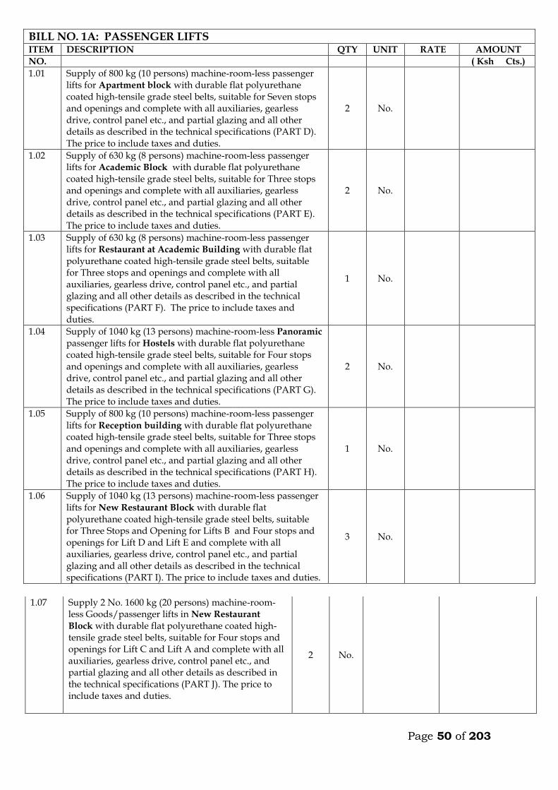
Page 50 of 203
1.07 Supply 2 No. 1600 kg (20 persons) machine-room-
less Goods/passenger lifts in New Restaurant
Block with durable flat polyurethane coated high-tensile grade steel belts, suitable for Four stops and openings for Lift C and Lift A and complete with all auxiliaries, gearless drive, control panel etc., and partial glazing and all other details as described in the technical specifications (PART J). The price to include taxes and duties.
2 No.
BILL NO. 1A: PASSENGER LIFTS ITEM DESCRIPTION QTY UNIT RATE AMOUNT
NO. ( Ksh Cts.)
1.01 Supply of 800 kg (10 persons) machine-room-less passenger lifts for Apartment block with durable flat polyurethane coated high-tensile grade steel belts, suitable for Seven stops and openings and complete with all auxiliaries, gearless drive, control panel etc., and partial glazing and all other details as described in the technical specifications (PART D). The price to include taxes and duties.
2 No.
1.02 Supply of 630 kg (8 persons) machine-room-less passenger lifts for Academic Block with durable flat polyurethane coated high-tensile grade steel belts, suitable for Three stops and openings and complete with all auxiliaries, gearless drive, control panel etc., and partial glazing and all other details as described in the technical specifications (PART E). The price to include taxes and duties.
2 No.
1.03 Supply of 630 kg (8 persons) machine-room-less passenger lifts for Restaurant at Academic Building with durable flat polyurethane coated high-tensile grade steel belts, suitable for Three stops and openings and complete with all auxiliaries, gearless drive, control panel etc., and partial glazing and all other details as described in the technical specifications (PART F). The price to include taxes and duties.
1 No.
1.04 Supply of 1040 kg (13 persons) machine-room-less Panoramic passenger lifts for Hostels with durable flat polyurethane coated high-tensile grade steel belts, suitable for Four stops and openings and complete with all auxiliaries, gearless drive, control panel etc., and partial glazing and all other details as described in the technical specifications (PART G). The price to include taxes and duties.
2 No.
1.05 Supply of 800 kg (10 persons) machine-room-less passenger lifts for Reception building with durable flat polyurethane coated high-tensile grade steel belts, suitable for Three stops and openings and complete with all auxiliaries, gearless drive, control panel etc., and partial glazing and all other details as described in the technical specifications (PART H). The price to include taxes and duties.
1 No.
1.06 Supply of 1040 kg (13 persons) machine-room-less passenger lifts for New Restaurant Block with durable flat polyurethane coated high-tensile grade steel belts, suitable for Three Stops and Opening for Lifts B and Four stops and openings for Lift D and Lift E and complete with all auxiliaries, gearless drive, control panel etc., and partial glazing and all other details as described in the technical specifications (PART I). The price to include taxes and duties.
3 No.
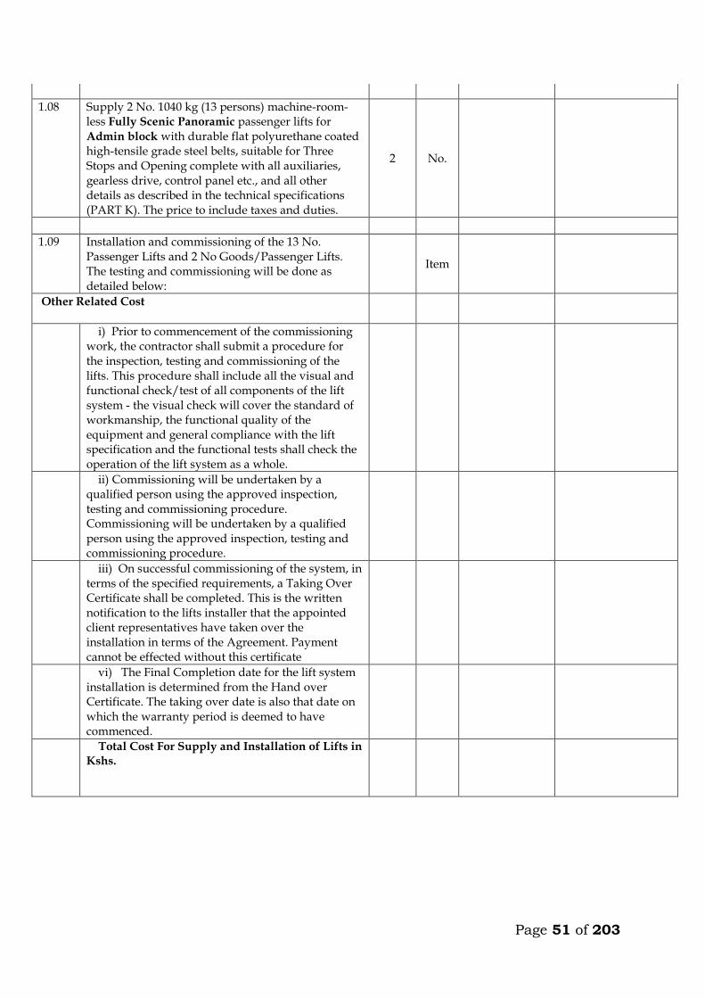
Page 51 of 203
1.08 Supply 2 No. 1040 kg (13 persons) machine-room-less Fully Scenic Panoramic passenger lifts for Admin block with durable flat polyurethane coated high-tensile grade steel belts, suitable for Three Stops and Opening complete with all auxiliaries, gearless drive, control panel etc., and all other details as described in the technical specifications (PART K). The price to include taxes and duties.
2 No.
1.09 Installation and commissioning of the 13 No. Passenger Lifts and 2 No Goods/Passenger Lifts. The testing and commissioning will be done as detailed below:
Item
Other Related Cost
i) Prior to commencement of the commissioning work, the contractor shall submit a procedure for the inspection, testing and commissioning of the lifts. This procedure shall include all the visual and functional check/test of all components of the lift system - the visual check will cover the standard of workmanship, the functional quality of the equipment and general compliance with the lift specification and the functional tests shall check the operation of the lift system as a whole.
ii) Commissioning will be undertaken by a qualified person using the approved inspection, testing and commissioning procedure. Commissioning will be undertaken by a qualified person using the approved inspection, testing and commissioning procedure.
iii) On successful commissioning of the system, in terms of the specified requirements, a Taking Over Certificate shall be completed. This is the written notification to the lifts installer that the appointed client representatives have taken over the installation in terms of the Agreement. Payment cannot be effected without this certificate
vi) The Final Completion date for the lift system installation is determined from the Hand over Certificate. The taking over date is also that date on which the warranty period is deemed to have commenced.
Total Cost For Supply and Installation of Lifts in Kshs.
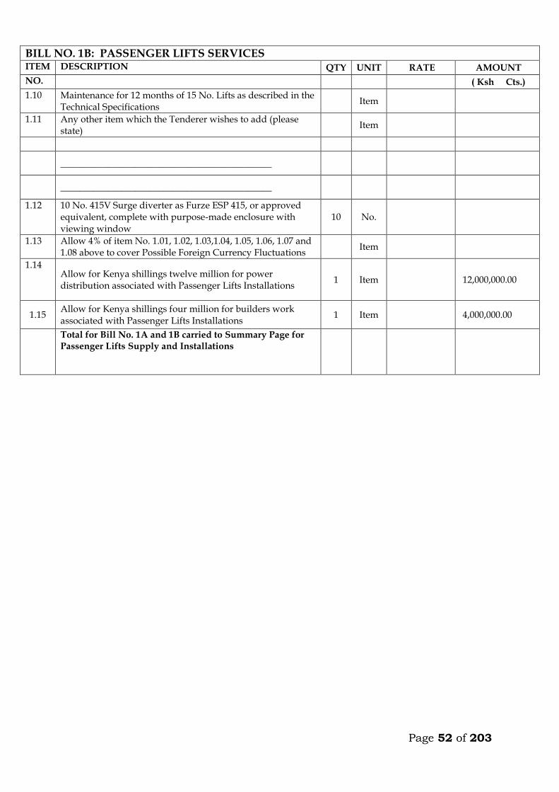
Page 52 of 203
BILL NO. 1B: PASSENGER LIFTS SERVICES ITEM DESCRIPTION QTY UNIT RATE AMOUNT
NO. ( Ksh Cts.)
1.10 Maintenance for 12 months of 15 No. Lifts as described in the Technical Specifications
Item
1.11 Any other item which the Tenderer wishes to add (please state)
Item
_____________________________________________
_____________________________________________
1.12 10 No. 415V Surge diverter as Furze ESP 415, or approved equivalent, complete with purpose-made enclosure with viewing window
10 No.
1.13 Allow 4% of item No. 1.01, 1.02, 1.03,1.04, 1.05, 1.06, 1.07 and 1.08 above to cover Possible Foreign Currency Fluctuations
Item
1.14 Allow for Kenya shillings twelve million for power distribution associated with Passenger Lifts Installations
1 Item 12,000,000.00
1.15 Allow for Kenya shillings four million for builders work associated with Passenger Lifts Installations
1 Item 4,000,000.00
Total for Bill No. 1A and 1B carried to Summary Page for Passenger Lifts Supply and Installations
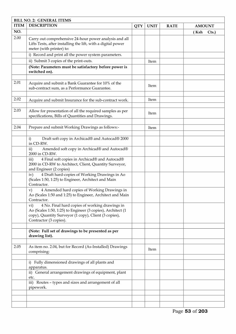
Page 53 of 203
BILL NO. 2: GENERAL ITEMS
ITEM DESCRIPTION QTY UNIT RATE AMOUNT
NO. ( Ksh Cts.)
2.00 Carry out comprehensive 24-hour power analysis and all Lifts Tests, after installing the lift, with a digital power meter (with printer) to:
i) Record and print all the power system parameters.
ii) Submit 3 copies of the print-outs. Item
(Note: Parameters must be satisfactory before power is switched on).
2.01 Acquire and submit a Bank Guarantee for 10% of the sub-contract sum, as a Performance Guarantee.
Item
2.02 Acquire and submit Insurance for the sub-contract work. Item
2.03 Allow for presentation of all the required samples as per specifications, Bills of Quantities and Drawings.
Item
2.04 Prepare and submit Working Drawings as follows:- Item
i) Draft soft copy in Archicad® and Autocad® 2000 in CD-RW.
ii) Amended soft copy in Archicad® and Autocad® 2000 in CD-RW.
iii) 4 Final soft copies in Archicad® and Autocad® 2000 in CD-RW to Architect, Client, Quantity Surveyor, and Engineer (2 copies)
iv) 4 Draft hard-copies of Working Drawings in Ao (Scales 1:50, 1:25) to Engineer, Architect and Main Contractor.
v) 4 Amended hard copies of Working Drawings in Ao (Scales 1:50 and 1:25) to Engineer, Architect and Main Contractor.
vi) 4 No. Final hard copies of working drawings in Ao (Scales 1:50, 1:25) to Engineer (3 copies), Architect (1 copy), Quantity Surveyor (1 copy), Client (3 copies), Contractor (3 copies).
(Note: Full set of drawings to be presented as per drawing list).
2.05 As item no. 2.04, but for Record (As-Installed) Drawings comprising:
Item
i) Fully dimensioned drawings of all plants and apparatus.
ii) General arrangement drawings of equipment, plant etc.
iii) Routes – types and sizes and arrangement of all pipework.
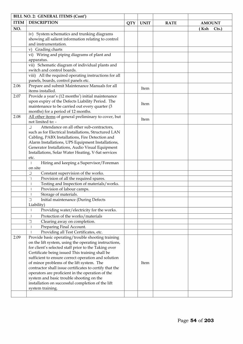
Page 54 of 203
BILL NO. 2: GENERAL ITEMS (Cont’)
ITEM DESCRIPTION QTY UNIT RATE AMOUNT
NO. ( Ksh Cts.)
iv) System schematics and trunking diagrams showing all salient information relating to control and instrumentation.
v) Grading charts
vi) Wiring and piping diagrams of plant and apparatus.
vii) Schematic diagram of individual plants and switch and control boards.
viii) All the required operating instructions for all panels, boards, control panels etc.
2.06 Prepare and submit Maintenance Manuals for all items installed.
Item
2.07 Provide a year’s (12 months’) initial maintenance upon expiry of the Defects Liability Period. The maintenance to be carried out every quarter (3 months) for a period of 12 months.
Item
2.08 All other items of general preliminary to cover, but not limited to: -
Item
Attendance on all other sub-contractors, such as for Electrical Installations, Structured LAN Cabling, PABX Installations, Fire Detection and Alarm Installations, UPS Equipment Installations, Generator Installations, Audio Visual Equipment Installations, Solar Water Heating, V-Sat services etc.
Hiring and keeping a Supervisor/Foreman on site
Constant supervision of the works.
Provision of all the required spares.
Testing and Inspection of materials/works.
Provision of labour camps.
Storage of materials.
Initial maintenance (During Defects Liability)
Providing water/electricity for the works.
Protection of the works/materials
Clearing away on completion.
Preparing Final Account.
Providing all Test Certificates, etc.
2.09 Provide basic operating/trouble shooting training on the lift system, using the operating instructions, for client’s selected staff prior to the Taking over Certificate being issued This training shall be sufficient to ensure correct operation and solution of minor problems of the lift system. The contractor shall issue certificates to certify that the operators are proficient in the operation of the system and basic trouble shooting on the installation on successful completion of the lift system training.
Item
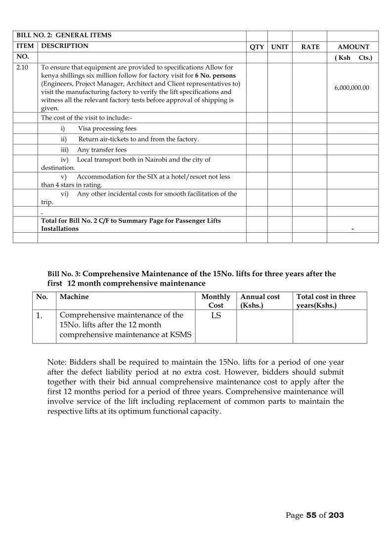
Page 55 of 203
Bill No. 3: Comprehensive Maintenance of the 15No. lifts for three years after the first 12 month comprehensive maintenance
No. Machine Monthly Cost
Annual cost (Kshs.)
Total cost in three years(Kshs.)
1. Comprehensive maintenance of the 15No. lifts after the 12 month comprehensive maintenance at KSMS
LS
Note: Bidders shall be required to maintain the 15No. lifts for a period of one year after the defect liability period at no extra cost. However, bidders should submit together with their bid annual comprehensive maintenance cost to apply after the first 12 months period for a period of three years. Comprehensive maintenance will involve service of the lift including replacement of common parts to maintain the respective lifts at its optimum functional capacity.
BILL NO. 2: GENERAL ITEMS
ITEM DESCRIPTION QTY UNIT RATE AMOUNT
NO. ( Ksh Cts.)
2.10 To ensure that equipment are provided to specifications Allow for kenya shillings six million follow for factory visit for 6 No. persons (Engineers, Project Manager, Architect and Client representatives to) visit the manufacturing factory to verify the lift specifications and witness all the relevant factory tests before approval of shipping is given.
6,000,000.00
The cost of the visit to include:-
i) Visa processing fees
ii) Return air-tickets to and from the factory.
iii) Any transfer fees
iv) Local transport both in Nairobi and the city of destination.
v) Accommodation for the SIX at a hotel/resort not less than 4 stars in rating.
vi) Any other incidental costs for smooth facilitation of the trip.
Total for Bill No. 2 C/F to Summary Page for Passenger Lifts Installations
-
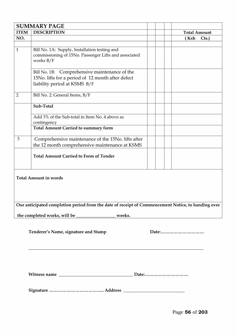
Page 56 of 203
Tenderer’s Name, signature and Stamp Date:………………………… ________________________________________________________________________________ Witness name __________________________________ Date:………………………… Signature ……………………………….. Address ____________________________
SUMMARY PAGE
ITEM DESCRIPTION Total Amount
NO. ( Ksh Cts.)
1 Bill No. 1A: Supply, Installation testing and commissioning of 15No. Passenger Lifts and associated works B/F
Bill No. 1B: Comprehensive maintenance of the 15No. lifts for a period of 12 month after defect liability period at KSMS B/F
2 Bill No. 2: General Items, B/F
Sub-Total
Add 3% of the Sub-total in Item No. 4 above as contingency
Total Amount Carried to summary form
3 Comprehensive maintenance of the 15No. lifts after the 12 month comprehensive maintenance at KSMS
Total Amount Carried to Form of Tender
Total Amount in words
Our anticipated completion period from the date of receipt of Commencement Notice, to handing over the completed works, will be __________________ weeks.
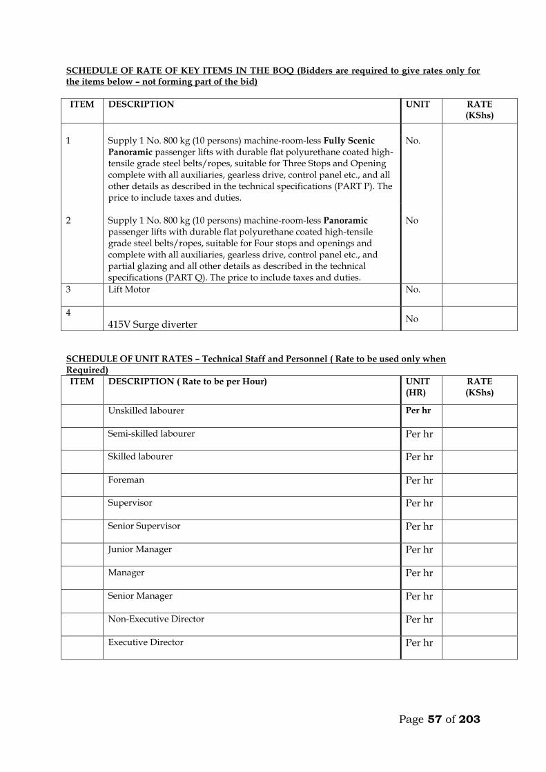
Page 57 of 203
SCHEDULE OF RATE OF KEY ITEMS IN THE BOQ (Bidders are required to give rates only for the items below – not forming part of the bid)
ITEM DESCRIPTION UNIT RATE (KShs)
1 Supply 1 No. 800 kg (10 persons) machine-room-less Fully Scenic
Panoramic passenger lifts with durable flat polyurethane coated high-tensile grade steel belts/ropes, suitable for Three Stops and Opening complete with all auxiliaries, gearless drive, control panel etc., and all other details as described in the technical specifications (PART P). The price to include taxes and duties.
No.
2 Supply 1 No. 800 kg (10 persons) machine-room-less Panoramic
passenger lifts with durable flat polyurethane coated high-tensile grade steel belts/ropes, suitable for Four stops and openings and complete with all auxiliaries, gearless drive, control panel etc., and partial glazing and all other details as described in the technical specifications (PART Q). The price to include taxes and duties.
No
3 Lift Motor
No.
4
415V Surge diverter No
SCHEDULE OF UNIT RATES – Technical Staff and Personnel ( Rate to be used only when Required)
ITEM DESCRIPTION ( Rate to be per Hour) UNIT (HR)
RATE (KShs)
Unskilled labourer
Per hr
Semi-skilled labourer
Per hr
Skilled labourer
Per hr
Foreman
Per hr
Supervisor
Per hr
Senior Supervisor
Per hr
Junior Manager
Per hr
Manager
Per hr
Senior Manager
Per hr
Non-Executive Director
Per hr
Executive Director
Per hr
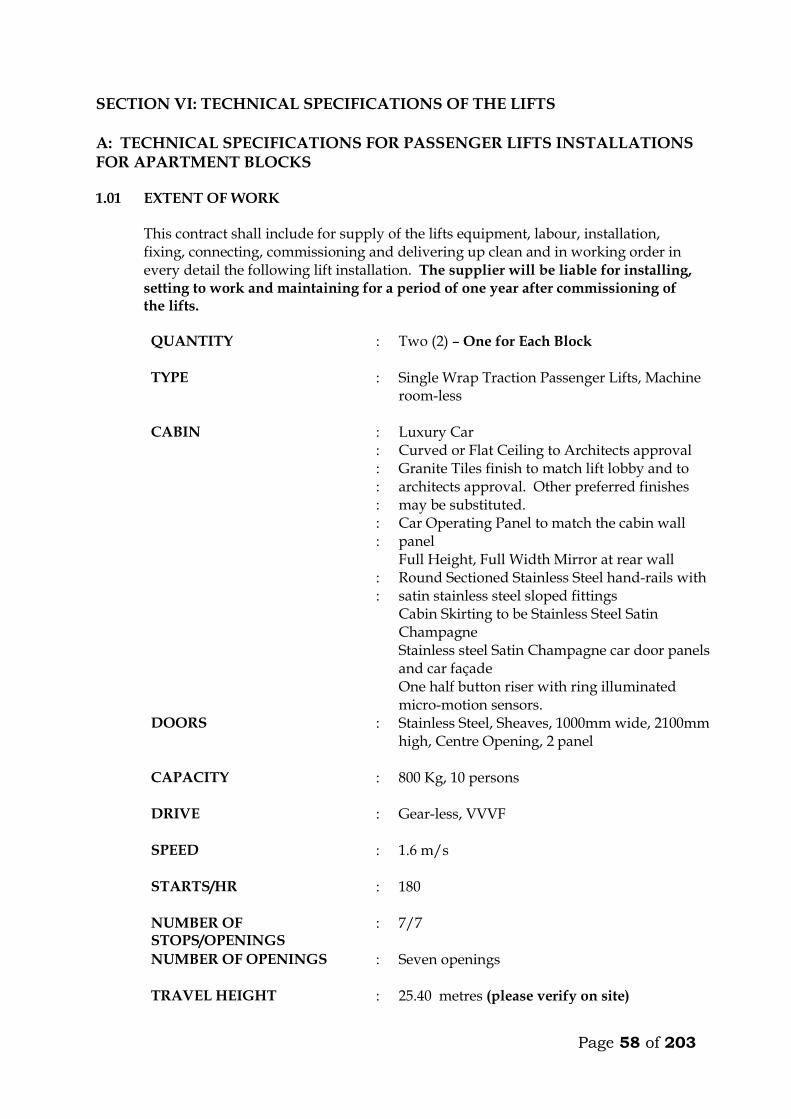
Page 58 of 203
SECTION VI: TECHNICAL SPECIFICATIONS OF THE LIFTS A: TECHNICAL SPECIFICATIONS FOR PASSENGER LIFTS INSTALLATIONS FOR APARTMENT BLOCKS 1.01 EXTENT OF WORK This contract shall include for supply of the lifts equipment, labour, installation,
fixing, connecting, commissioning and delivering up clean and in working order in every detail the following lift installation. The supplier will be liable for installing, setting to work and maintaining for a period of one year after commissioning of the lifts.
QUANTITY : Two (2) – One for Each Block
TYPE : Single Wrap Traction Passenger Lifts, Machine
room-less
CABIN : : : : : : : : :
Luxury Car Curved or Flat Ceiling to Architects approval Granite Tiles finish to match lift lobby and to architects approval. Other preferred finishes may be substituted. Car Operating Panel to match the cabin wall panel Full Height, Full Width Mirror at rear wall Round Sectioned Stainless Steel hand-rails with satin stainless steel sloped fittings Cabin Skirting to be Stainless Steel Satin Champagne Stainless steel Satin Champagne car door panels and car façade One half button riser with ring illuminated micro-motion sensors.
DOORS : Stainless Steel, Sheaves, 1000mm wide, 2100mm high, Centre Opening, 2 panel
CAPACITY : 800 Kg, 10 persons
DRIVE : Gear-less, VVVF
SPEED : 1.6 m/s
STARTS/HR : 180
NUMBER OF STOPS/OPENINGS
: 7/7
NUMBER OF OPENINGS : Seven openings
TRAVEL HEIGHT : 25.40 metres (please verify on site)
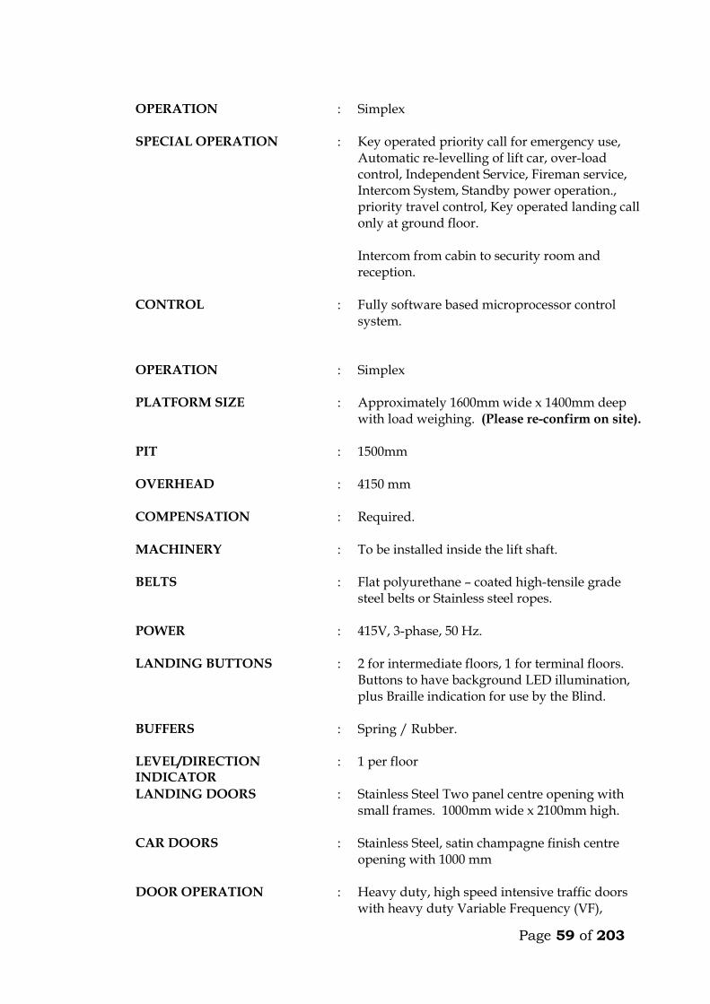
Page 59 of 203
OPERATION : Simplex
SPECIAL OPERATION : Key operated priority call for emergency use,
Automatic re-levelling of lift car, over-load control, Independent Service, Fireman service, Intercom System, Standby power operation., priority travel control, Key operated landing call only at ground floor. Intercom from cabin to security room and reception.
CONTROL : Fully software based microprocessor control system.
OPERATION : Simplex
PLATFORM SIZE : Approximately 1600mm wide x 1400mm deep
with load weighing. (Please re-confirm on site).
PIT : 1500mm
OVERHEAD : 4150 mm
COMPENSATION : Required.
MACHINERY : To be installed inside the lift shaft.
BELTS : Flat polyurethane – coated high-tensile grade steel belts or Stainless steel ropes.
POWER : 415V, 3-phase, 50 Hz.
LANDING BUTTONS : 2 for intermediate floors, 1 for terminal floors. Buttons to have background LED illumination, plus Braille indication for use by the Blind.
BUFFERS : Spring / Rubber.
LEVEL/DIRECTION INDICATOR
: 1 per floor
LANDING DOORS : Stainless Steel Two panel centre opening with small frames. 1000mm wide x 2100mm high.
CAR DOORS : Stainless Steel, satin champagne finish centre opening with 1000 mm
DOOR OPERATION : Heavy duty, high speed intensive traffic doors with heavy duty Variable Frequency (VF),
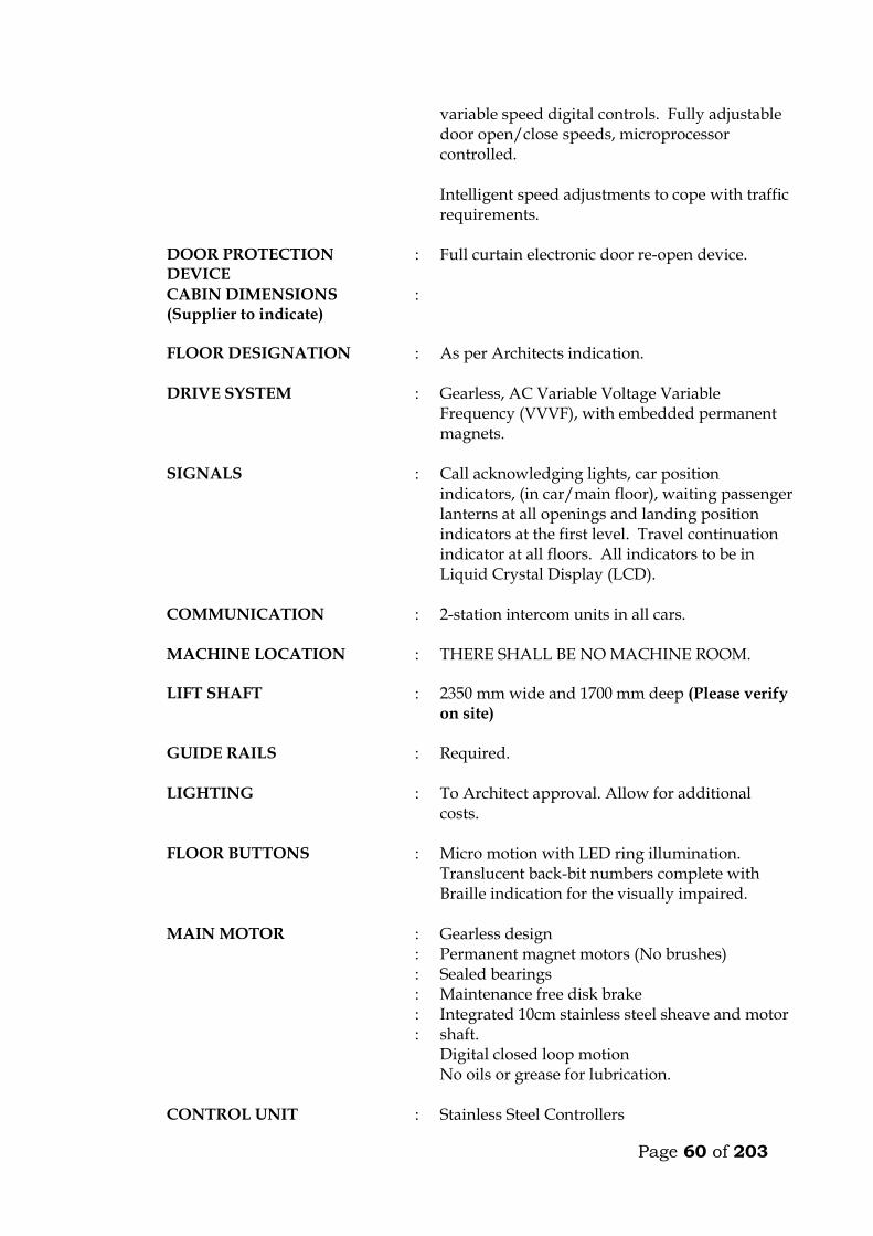
Page 60 of 203
variable speed digital controls. Fully adjustable door open/close speeds, microprocessor controlled. Intelligent speed adjustments to cope with traffic requirements.
DOOR PROTECTION DEVICE
: Full curtain electronic door re-open device.
CABIN DIMENSIONS (Supplier to indicate)
:
FLOOR DESIGNATION : As per Architects indication.
DRIVE SYSTEM : Gearless, AC Variable Voltage Variable Frequency (VVVF), with embedded permanent magnets.
SIGNALS : Call acknowledging lights, car position indicators, (in car/main floor), waiting passenger lanterns at all openings and landing position indicators at the first level. Travel continuation indicator at all floors. All indicators to be in Liquid Crystal Display (LCD).
COMMUNICATION : 2-station intercom units in all cars.
MACHINE LOCATION
: THERE SHALL BE NO MACHINE ROOM.
LIFT SHAFT : 2350 mm wide and 1700 mm deep (Please verify on site)
GUIDE RAILS : Required.
LIGHTING : To Architect approval. Allow for additional costs.
FLOOR BUTTONS : Micro motion with LED ring illumination. Translucent back-bit numbers complete with Braille indication for the visually impaired.
MAIN MOTOR : : : : : :
Gearless design Permanent magnet motors (No brushes) Sealed bearings Maintenance free disk brake Integrated 10cm stainless steel sheave and motor shaft. Digital closed loop motion No oils or grease for lubrication.
CONTROL UNIT : Stainless Steel Controllers
Page 61 of 203
E-Pac to prevent electronic interference. Digital closed loop VF drive with vector control with digital speed encoder.
CAR OPERATING PANEL : 1 No fitted on the side panel. To be complete with the following: electro-luminescent back-lit button, micro-motion buttons, intercom speaker, audio/visual overload, key switch for fan, key switch for lights.
LANDING FIXTURES : Wide angle view combined hall position indicators with signal hall lanterns in high resolution LCD on ground floor. Elegantly designed hall buttons with ring illumination.
OTHERS : Two station intercom system. (Car and reception. : Compact Disc Music in car. (Wiring only, music
by others). : Speaker micro-phone built in car operating
panel. : Speech synthesis. : Door open button. : Door close button. : Forced ventilation key switch : Floor levelling guaranteed + 3mm. : Independent service key switch. : Emergency fire service. : Quite-operation, drought-free multi-directional
cabin extract fan. : Audio/Visual car overload indication device. : Powerful quiet, drought free multi-directional
cabin extract fan. : Electronic Reverse Phase Relay built in
controller. : Siren type emergency alarm system.
POWER SUPPLY : :
Mains 3 phase / 50 Hz Lighting 1 phase – 240 v
FLOOR LEVELLING : + 3mm guaranteed
HEAT DISSIPATION : 0.7 KJ/S
CODE COMPLIANCE : European Code EN 81 or British Standard Specification Equivalent (BS5655)
MOTOR RATING : Kw
STARTING CURRENT : Amps
Page 62 of 203
NOMINAL CURRENT : Amps
SHEAVE : Stainless Steel
MISCELLANEOUS : Heat sensor in the machine room and controller
to shut the car as its safety levels at the next landing.
: Rescue operation during power failure with emergency and inspection panel, to move the car to the next landing in event of power failure.
: Electronic light ray device and infrared curtain on car doors.
: Door lock monitoring to put the car on inspection when safety circuits malfunction.
CODE COMPLIANCE : European Code EN 81.
STANDARD : BS 5655 / EN 81
COUNTER WEIGHT : Required. Immediately after appointment the contractor shall provide to the Engineer a general
arrangement drawing showing important dimensions and weights of the lifts, and submit colour samples for the Engineer’s approval.
The contractor must provide all beams, brackets and fixing devices for fixing of
guide rails, counter weights, buffers, door frames, architraves etc. All fixing devices to be cast in or cut into structural walls shall be supplied and fixed
by the contractor. It is the responsibility of the contractor alone to ensure that such devices are cast in or otherwise fixed in the right position and in a proper manner.
1.02 WORK BY OTHERS
Excluded from this sub-contract is lighting in the plant room and the electrical power supply which shall be brought up to an isolator and distribution board in the plant room by others. Connection to machinery and for lighting in cars shall be carried out by the lift sub-contractor.
Page 63 of 203
1.03 OPERATION
The car shall travel at a maximum speed of 1.6m/s in all floors. The car must not start unless the car doors are in a closed position and all landing doors are locked in a closed position. Should the load on the car exceed the maximum load, the car and landing doors are to be prevented from closing. Car levelling shall be within 12mm by means of an automatic self-levelling device. An emergency stop button in the car shall stop the car completely even after the button is released. Re-starting shall take place only by activation of a push button in the car and not by a call from any landing. Terminal limit switches must stop the car automatically at the terminal landings. Final limit switches must cut off power and apply the brake automatically, should the car pass the terminal landings. The installation must be provided with a complete controller device to control starting, stopping and speed as well as emergency stopping of the car in case any of the safety devices do not operate or excessive descending or ascending speed is attained by cutting off power to the motor and activation of the brake. Calls in the car must be given preference over calls from landings. At ground floor, calls shall be by means of a key operated switch only for authorised people. The car must deal with calls in sequence and not be intercepted during their trips by additional calls from car or landings. The lift must be provided with automatic bypass devices to prevent unnecessary stops when the car is full. The car must not stop during the “up” trip at any landing in response to a “down” landing call, unless this call is the highest one registered. For inspection purpose a manually operated switch on the controller connected to “up” and “down” direction buttons exposed on the top of the car, must be provided. This switch must permit the car to be operated at slow speed from the top of the car. During this inspection the car must not respond to any calls.
Page 64 of 203
1.04 CAR The car frame which supports the car platform and enclosure shall be made of solid
structural steel with welded, bolted or riveted joints. Bolts used must be positioned for easy adjustment. Car finishes shall be:-
FLOOR FINISH : Granite Tiles finish to match lift lobby and to architects approval. Other preferred finishes may be substituted.
REAR – WALLS : Full width full height mirror.
HANDRAIL : On 3 walls to be stainless steel satin sloped fittings.
SIDE WALLS : Stainless steel champagne CAR DOORS : Stainless Steel, satin champagne finish LANDING DOORS : Stainless Steel, satin finish.
CEILING : Curved or Flat ceiling to be approved by
the architect including lighting. To be fitted with a silent exhaust fan yielding approximately 650 m³/hr. Allow for any additional costs.
LIGHTING : To be chosen by the Architect. Allow for additional costs.
The colour and type of finishes shall be approved by the Architect before ordering. Car shall be equipped with 2 sets of illuminated push or touch buttons in silver
anodized or stainless steel flush mounted operating panel. The operating panel in car must comprise: . Floor buttons, one of each floor served . Emergency call button . Car inspection switch . Emergency stop button Car shall have direction of travel indicators at high level. Car shall also be equipped with a digital floor position indicator above the sliding
doors. All lamps, buttons, etc., must be changeable from within the car.
Page 65 of 203
All material used shall be approved by the local fire authority. A load plate shall also be fitted in the car showing the maximum load allowed, in
kilograms and number of passengers. 1.05 DOORS AND ARCHITRAVES The entrance to the car to be provided with two panel automatic centre opening
stainless steel, satin finished sliding doors, guided at the bottom by non-metallic shoes sliding in suitable grooves. Doors are to be installed both in car and landings. The doors must be complete with electronic mechanical interlock and emergency opening key.
The car must be stopped and prevented from moving should a door be forced open. The car doors and the landing doors must open automatically when levelling, the
opening to start as the car is approximately 250mm from the landing. The car door and landing door to move simultaneously in opening and closing, being 5 seconds (to be adjustable). In open position the doors automatically have to move back to locked position, even if the car is stationary at the landing. By means of sensitive edge and one photocell the doors have to stop and reverse during their closing cycle if obstructed.
All door panels in landings and car (like all walls) to be made from materials
described earlier. All architraves to be made from spray painted matt finish steel. All plugs, brackets, etc., for architrave-fixing to be provided by the sub-contractor, and cast in by the sub-contractor. The appearance of the cabin will have to be approved by the Architect before ordering.
It is emphasized that great importance is attached to silent functioning of the doors.
1.06 LANDING CALL BUTTONS At each mid-landing, two stainless steel flush-mounted panels, with two push or
touch buttons for “up” and “down” traffic shall be provided. The buttons must light up when a call is registered.
Direction arrow lights shall be incorporated in all landing call panels, arranged so
that when a button is pressed the corresponding arrow will illuminate indicating the direction of the call which is registered.
At terminal landings one button only to be installed in each landing panel. At ground floor illuminated digital car travel position indicators with arrows shall be
placed above the door. 1.07 SHAFT INSTALLATIONS Guide rails for car and counterweights to be T-steel guide rails planed on three
edges. Rails must be placed accurately and fixed firmly to the shaft walls with
Page 66 of 203
sufficient spacing between brackets. The rails shall be brought totally to the bottom of the shaft.
The fixing of rails and the connection between two or more sections of rail must be in
such a manner that the straight and vertical position is not influenced by changes in temperature or ordinary settlement in the structure.
Guide rails for the car to be either rubber roller guides or Telfon (Tufnol). Roller and
shoes shall be renewable. Buffer must be provided to bring the car counterweight to rest at the extreme limits
of travel, should the car for any reason pass the limit switches. The guide rails, roller shoes, buffers, counter-weight all to be provided and installed
by the Sub-contractor. 1.08 LIFTING MACHINERY
The machine shall be gearless, single wrap traction type, mounted on steel beams fitted on the shaft walls. The beams to be as per structural engineers details. The following information on the machinery must accompany the tender. Make Size, h.p. Voltage, V Power consumption at full load, KW Revolutions per minute, r.p.m. Full load current, A Starting current, A Duration of starting current, sec
Power factor, cos Acceleration time, sec Retardation time, sec The motor must be provided with overload and phase failure cutout devices. The control system to be fitted with a special batter/charger to enable technicians to move cabin to the nearest level to release trapped passengers in case of power failure. The system must prevent engaging of the turning device, until the power supply for the motor is switched off. The aggregate must be dimensioned for the full load in continuous operation and for a temporary overload of 10%. The sub-contractor must provide information on the highest permissible operating temperature for optional functioning of the lift, and about the heat produced by the entire installation.
1.09 ROPES AND SHEAVES
Page 67 of 203
The lift shall be provided with durable, flat polyurethane-coated high-tensile steel belts. Ropes maybe substituted but subject to engineers approval.
The sheaves shall be of ample diameter for ropes used. Sheaves shall be fixed by
means of iron beams which are supplied and installed by the sub-contractor. Beams must be sound insulated from structural parts.
1.10 ELECTRICAL INSTALLATION All motors and switchgear shall be rated for operation at 240V/415V, 50 cycles.
Relays and components must be tropicalised. The installation must comply with the IEE Regulations. All wiring shall be carried
out in a neat and orderly manner. Cables run on walls or ceilings to be in straight line and right angle bends enclosed in steel ducting.
Connections to equipment more than 400mm from wall shall be run from the wall in
conduit cast in the floor to a connector box fixed upright adjacent to the equipment and through flexible conduit to the equipment.
All electrical switchgear must be clearly labelled. 1.11 ALARM
An alarm button in the car shall simultaneously activate a bell situated on the car and bell positioned at the security station near the lift lobby at ground floor. The bells shall be supplied with power from a rechargeable dry cell battery supplied by sub-contractor. All wiring and installation of the alarm system shall be done by the sub-contractor.
1.12 CONTROL AND DISPLAY SYSTEM A control and display system shall be provided at the security room. The system, comprising a colour video monitor and keyboard shall indicate real-time elevator status, passenger traffic and demand, etc. It shall also be possible to feed commands to the controller from the keyboard, to adjust operation of the cars and for faults diagnosis.
Page 68 of 203
TECHNICAL DETAILS OF LIFTS OFFERED BY THE TENDERER FOR APARTMENT BLOCKS 1. Lifting Machinery
a) Make b) Size, h.p. c) Power consumption at full load, KW d) Revolutions per minute, r.p.m. e) Full load current, A f) Starting current, A g) Duration of starting current, sec
h) Power factor, cos i) Acceleration time, sec j) Retardation time, sec
2. Delivery Details
Time in weeks from acceptance of tender to delivery of all equipment on site ________ Weeks.
Time in weeks from acceptance of tender to installation and commissioning _________ Weeks. 3. Deviations from the Specification
The Tenderer shall give below details of any Specification, or any deviations, omissions, additions of alternatives in respect of the lifts which he is offering. If none, write None.

Page 69 of 203
MAINTENANCE CONTRACT The Tenderer shall insert in this section the cost of a fully comprehensive Maintenance Contract after one of the initial 12 months maintenance or defects liability period. The sum to be inclusive of regular monthly inspection and breakdown service, and shall include for all tools, parts replacement and service material such as oils, lubricants, etc. ITEM KSHS. Annual Maintenance cost for 1 No. lifts as described
in the following pages inclusive of all spares and 24 hour call services (start date assumed end of building contract). _______________ WARRANTY The warranty period for the equipment and all the associated accessories shall be _______________ months from the date of commissioning. (A minimum of 12 months will be allowed). FOREIGN CURRENCY State the foreign currency applied and the exchange rate to the Kenya Shilling. 1 ____________________ (Foreign Currency) = _____________________ KSh.
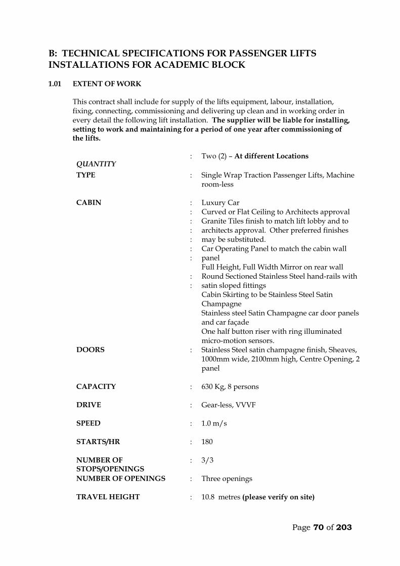
Page 70 of 203
B: TECHNICAL SPECIFICATIONS FOR PASSENGER LIFTS INSTALLATIONS FOR ACADEMIC BLOCK 1.01 EXTENT OF WORK This contract shall include for supply of the lifts equipment, labour, installation,
fixing, connecting, commissioning and delivering up clean and in working order in every detail the following lift installation. The supplier will be liable for installing, setting to work and maintaining for a period of one year after commissioning of the lifts.
QUANTITY : Two (2) – At different Locations
TYPE : Single Wrap Traction Passenger Lifts, Machine room-less
CABIN : : : : : : : : :
Luxury Car Curved or Flat Ceiling to Architects approval Granite Tiles finish to match lift lobby and to architects approval. Other preferred finishes may be substituted. Car Operating Panel to match the cabin wall panel Full Height, Full Width Mirror on rear wall Round Sectioned Stainless Steel hand-rails with satin sloped fittings Cabin Skirting to be Stainless Steel Satin Champagne Stainless steel Satin Champagne car door panels and car façade One half button riser with ring illuminated micro-motion sensors.
DOORS : Stainless Steel satin champagne finish, Sheaves, 1000mm wide, 2100mm high, Centre Opening, 2 panel
CAPACITY : 630 Kg, 8 persons
DRIVE : Gear-less, VVVF
SPEED : 1.0 m/s
STARTS/HR : 180
NUMBER OF STOPS/OPENINGS
: 3/3
NUMBER OF OPENINGS : Three openings
TRAVEL HEIGHT : 10.8 metres (please verify on site)
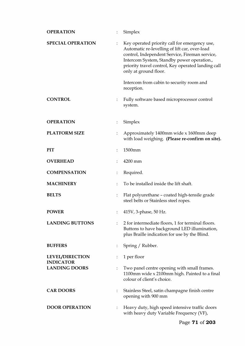
Page 71 of 203
OPERATION : Simplex
SPECIAL OPERATION : Key operated priority call for emergency use, Automatic re-levelling of lift car, over-load control, Independent Service, Fireman service, Intercom System, Standby power operation., priority travel control, Key operated landing call only at ground floor. Intercom from cabin to security room and reception.
CONTROL : Fully software based microprocessor control system.
OPERATION : Simplex
PLATFORM SIZE : Approximately 1400mm wide x 1600mm deep
with load weighing. (Please re-confirm on site).
PIT : 1500mm
OVERHEAD : 4200 mm
COMPENSATION : Required.
MACHINERY : To be installed inside the lift shaft.
BELTS : Flat polyurethane – coated high-tensile grade steel belts or Stainless steel ropes.
POWER : 415V, 3-phase, 50 Hz.
LANDING BUTTONS : 2 for intermediate floors, 1 for terminal floors. Buttons to have background LED illumination, plus Braille indication for use by the Blind.
BUFFERS : Spring / Rubber.
LEVEL/DIRECTION INDICATOR
: 1 per floor
LANDING DOORS : Two panel centre opening with small frames. 1100mm wide x 2100mm high. Painted to a final colour of client’s choice.
CAR DOORS : Stainless Steel, satin champagne finish centre opening with 900 mm
DOOR OPERATION : Heavy duty, high speed intensive traffic doors with heavy duty Variable Frequency (VF),

Page 72 of 203
variable speed digital controls. Fully adjustable door open/close speeds, microprocessor controlled. Intelligent speed adjustments to cope with traffic requirements.
DOOR PROTECTION DEVICE
: Full curtain electronic door re-open device.
CABIN DIMENSIONS (Supplier to indicate)
:
FLOOR DESIGNATION : As per Architects indication.
DRIVE SYSTEM : Gearless, AC Variable Voltage Variable Frequency (VVVF), with embedded permanent magnets.
SIGNALS : Call acknowledging lights, car position indicators, (in car/main floor), waiting passenger lanterns at all openings and landing position indicators at the first level. Travel continuation indicator at all floors. All indicators to be in Liquid Crystal Display (LCD).
COMMUNICATION : 2-station intercom units in all cars.
MACHINE LOCATION
: THERE SHALL BE NO MACHINE ROOM.
LIFT SHAFT : 1800 mm wide and 1800 mm deep (Please verify on site)
GUIDE RAILS : Required.
LIGHTING : To Architect approval. Allow for additional costs.
FLOOR BUTTONS : Micro motion with LED ring illumination. Translucent back-bit numbers complete with Braille indication for the visually impaired.
MAIN MOTOR : : : : : :
Gearless design Permanent magnet motors (No brushes) Sealed bearings Maintenance free disk brake Integrated 10cm stainless steel sheave and motor shaft. Digital closed loop motion No oils or grease for lubrication.

Page 73 of 203
CONTROL UNIT : Stainless Steel Controllers E-Pac to prevent electronic interference. Digital closed loop VF drive with vector control with digital speed encoder.
CAR OPERATING PANEL : 1 No fitted on the side panel. To be complete with the following: electro-luminescent back-lit button, micro-motion buttons, intercom speaker, audio/visual overload, key switch for fan, key switch for lights.
LANDING FIXTURES : Wide angle view combined hall position indicators with signal hall lanterns in high resolution LCD on ground floor. Elegantly designed hall buttons with ring illumination.
OTHERS : Two station intercom system. (Car and reception. : Compact Disc Music in car. (Wiring only, music
by others). : Speaker micro-phone built in car operating
panel. : Speech synthesis. : Door open button. : Door close button. : Forced ventilation key switch : Floor levelling guaranteed + 3mm. : Independent service key switch. : Emergency fire service. : Quite-operation, drought-free multi-directional
cabin extract fan. : Audio/Visual car overload indication device. : Powerful quiet, drought free multi-directional
cabin extract fan. : Electronic Reverse Phase Relay built in
controller. : Siren type emergency alarm system.
POWER SUPPLY : :
Mains 3 phase / 50 Hz Lighting 1 phase – 240 v
FLOOR LEVELLING : + 3mm guaranteed
HEAT DISSIPATION : 0.7 KJ/S
CODE COMPLIANCE : European Code EN 81 or British Standard Specification Equivalent (BS5655)
MOTOR RATING : Kw

Page 74 of 203
STARTING CURRENT : Amps
NOMINAL CURRENT : Amps
SHEAVE : Stainless Steel
MISCELLANEOUS : Heat sensor in the machine room and controller to shut the car as its safety levels at the next landing.
: Rescue operation during power failure with emergency and inspection panel, to move the car to the next landing in event of power failure.
: Electronic light ray device and infrared curtain on car doors.
: Door lock monitoring to put the car on inspection when safety circuits malfunction.
CODE COMPLIANCE : European Code EN 81.
STANDARD : BS 5655 / EN 81
COUNTER WEIGHT : Required. Immediately after appointment the contractor shall provide to the Engineer a general
arrangement drawing showing important dimensions and weights of the lifts, and submit colour samples for the Engineer’s approval.
The contractor must provide all beams, brackets and fixing devices for fixing of
guide rails, counter weights, buffers, door frames, architraves etc. All fixing devices to be cast in or cut into structural walls shall be supplied and fixed
by the contractor. It is the responsibility of the contractor alone to ensure that such devices are cast in or otherwise fixed in the right position and in a proper manner.
1.02 WORK BY OTHERS
Excluded from this sub-contract is lighting in the plant room and the electrical power supply which shall be brought up to an isolator and distribution board in the plant room by others. Connection to machinery and for lighting in cars shall be carried out by the lift sub-contractor.
Page 75 of 203
1.03 OPERATION
The car shall travel at a maximum speed of 1.0m/s in all floors. The car must not start unless the car doors are in a closed position and all landing doors are locked in a closed position. Should the load on the car exceed the maximum load, the car and landing doors are to be prevented from closing. Car levelling shall be within 12mm by means of an automatic self-levelling device. An emergency stop button in the car shall stop the car completely even after the button is released. Re-starting shall take place only by activation of a push button in the car and not by a call from any landing. Terminal limit switches must stop the car automatically at the terminal landings. Final limit switches must cut off power and apply the brake automatically, should the car pass the terminal landings. The installation must be provided with a complete controller device to control starting, stopping and speed as well as emergency stopping of the car in case any of the safety devices do not operate or excessive descending or ascending speed is attained by cutting off power to the motor and activation of the brake. Calls in the car must be given preference over calls from landings. At ground floor, calls shall be by means of a key operated switch only for authorised people. The car must deal with calls in sequence and not be intercepted during their trips by additional calls from car or landings. The lift must be provided with automatic bypass devices to prevent unnecessary stops when the car is full. The car must not stop during the “up” trip at any landing in response to a “down” landing call, unless this call is the highest one registered. For inspection purpose a manually operated switch on the controller connected to “up” and “down” direction buttons exposed on the top of the car, must be provided. This switch must permit the car to be operated at slow speed from the top of the car. During this inspection the car must not respond to any calls.
Page 76 of 203
1.04 CAR The car frame which supports the car platform and enclosure shall be made of solid
structural steel with welded, bolted or riveted joints. Bolts used must be positioned for easy adjustment. Car finishes shall be : -
FLOOR FINISH : Granite Tiles finish to match lift lobby and
to architects approval. Other preferred finishes may be substituted.
REAR – WALLS : Full width full height mirror.
HANDRAIL : On 3 walls to be stainless steel satin sloped fittings.
SIDE WALLS : Stainless steel champagne.
CAR DOORS : Stainless Steel, satin champagne finish.
LANDING DOORS : Stainless Steel, satin finish.
CEILING : Curved or Flat ceiling to be approved by the architect including lighting. To be fitted with a silent exhaust fan yielding approximately 650 m³/hr. Allow for any additional costs.
LIGHTING : To be chosen by the Architect. Allow for additional costs.
The colour and type of finishes shall be approved by the Architect before ordering. Car shall be equipped with 2 sets of illuminated push or touch buttons in silver
anodized or stainless steel flush mounted operating panel. The operating panel in car must comprise: . Floor buttons, one of each floor served . Emergency call button . Car inspection switch . Emergency stop button Car shall have direction of travel indicators at high level. Car shall also be equipped with a digital floor position indicator above the sliding
doors.
Page 77 of 203
All lamps, buttons, etc., must be changeable from within the car. All material used shall be approved by the local fire authority. A load plate shall also be fitted in the car showing the maximum load allowed, in
kilograms and number of passengers. 1.05 DOORS AND ARCHITRAVES The entrance to the car to be provided with two panel automatic centre opening
stainless steel, satin finished sliding doors, guided at the bottom by non-metallic shoes sliding in suitable grooves. Doors are to be installed both in car and landings. The doors must be complete with electronic mechanical interlock and emergency opening key.
The car must be stopped and prevented from moving should a door be forced open. The car doors and the landing doors must open automatically when levelling, the
opening to start as the car is approximately 250mm from the landing. The car door and landing door to move simultaneously in opening and closing, being 5 seconds (to be adjustable). In open position the doors automatically have to move back to locked position, even if the car is stationary at the landing. By means of sensitive edge and one photocell the doors have to stop and reverse during their closing cycle if obstructed.
All door panels in landings and car (like all walls) to be made from materials
described earlier. All architraves to be made from spray painted matt finish steel. All plugs, brackets, etc., for architrave-fixing to be provided by the sub-contractor, and cast in by the sub-contractor. The appearance of the cabin will have to be approved by the Architect before ordering.
It is emphasized that great importance is attached to silent functioning of the doors.
1.06 LANDING CALL BUTTONS At each mid-landing, two stainless steel flush-mounted panels, with two push or
touch buttons for “up” and “down” traffic shall be provided. The buttons must light up when a call is registered.
Direction arrow lights shall be incorporated in all landing call panels, arranged so
that when a button is pressed the corresponding arrow will illuminate indicating the direction of the call which is registered.
At terminal landings one button only to be installed in each landing panel. At ground floor illuminated digital car travel position indicators with arrows shall be
placed above the door.
Page 78 of 203
1.07 SHAFT INSTALLATIONS Guide rails for car and counterweights to be T-steel guide rails planed on three
edges. Rails must be placed accurately and fixed firmly to the shaft walls with sufficient spacing between brackets. The rails shall be brought totally to the bottom of the shaft.
The fixing of rails and the connection between two or more sections of rail must be in
such a manner that the straight and vertical position is not influenced by changes in temperature or ordinary settlement in the structure.
Guide rails for the car to be either rubber roller guides or Telfon (Tufnol). Roller and
shoes shall be renewable. Buffer must be provided to bring the car counterweight to rest at the extreme limits
of travel, should the car for any reason pass the limit switches. The guide rails, roller shoes, buffers, counter-weight all to be provided and installed
by the Sub-contractor. 1.08 LIFTING MACHINERY
The machine shall be gearless, single wrap traction type, mounted on steel beams fitted on the shaft walls. The beams to be as per structural engineer’s details. The following information on the machinery must accompany the tender. Make Size, h.p. Voltage, V Power consumption at full load, KW Revolutions per minute, r.p.m. Full load current, A Starting current, A Duration of starting current, sec
Power factor, cos Acceleration time, sec Retardation time, sec The motor must be provided with overload and phase failure cutout devices. The control system to be fitted with a special batter/charger to enable technicians to move cabin to the nearest level to release trapped passengers in case of power failure. The system must prevent engaging of the turning device, until the power supply for the motor is switched off. The aggregate must be dimensioned for the full load in continuous operation and for a temporary overload of 10%. The sub-contractor must provide information on the highest permissible operating temperature for optional functioning of the lift, and about the heat produced by the entire installation.
Page 79 of 203
1.09 ROPES AND SHEAVES The lift shall be provided with durable, flat polyurethane-coated high-tensile steel
belts. Ropes maybe substituted but subject to engineer’s approval. The sheaves shall be of ample diameter for ropes used. Sheaves shall be fixed by
means of iron beams which are supplied and installed by the sub-contractor. Beams must be sound insulated from structural parts.
1.10 ELECTRICAL INSTALLATION All motors and switchgear shall be rated for operation at 240V/415V, 50 cycles.
Relays and components must be tropicalised. The installation must comply with the IEE Regulations. All wiring shall be carried
out in a neat and orderly manner. Cables run on walls or ceilings to be in straight line and right angle bends enclosed in steel ducting.
Connections to equipment more than 400mm from wall shall be run from the wall in
conduit cast in the floor to a connector box fixed upright adjacent to the equipment and through flexible conduit to the equipment.
All electrical switchgear must be clearly labelled. 1.11 ALARM
An alarm button in the car shall simultaneously activate a bell situated on the car and bell positioned at the security station near the lift lobby at ground floor. The bells shall be supplied with power from a rechargeable dry cell battery supplied by sub-contractor. All wiring and installation of the alarm system shall be done by the sub-contractor.

Page 80 of 203
TECHNICAL DETAILS OF LIFTS OFFERED BY THE TENDERER 3. Lifting Machinery
a) Make b) Size, h.p. c) Power consumption at full load, KW d) Revolutions per minute, r.p.m. e) Full load current, A f) Starting current, A g) Duration of starting current, sec
h) Power factor, cos i) Acceleration time, sec j) Retardation time, sec
4. Delivery Details
Time in weeks from acceptance of tender to delivery of all equipment on site ________ Weeks.
Time in weeks from acceptance of tender to installation and commissioning _________ Weeks. 3. Deviations from the Specification
The Tenderer shall give below details of any Specification, or any deviations, omissions, additions of alternatives in respect of the lifts which he is offering. If none, write None.
Page 81 of 203
MAINTENANCE CONTRACT The Tenderer shall insert in this section the cost of a fully comprehensive Maintenance Contract after one of the initial 12 months maintenance or defects liability period. The sum to be inclusive of regular monthly inspection and breakdown service, and shall include for all tools, parts replacement and service material such as oils, lubricants, etc. ITEM KSHS. Annual Maintenance cost for 1 No. lifts as described
in the following pages inclusive of all spares and 24 hour call services (start date assumed end of building contract). _______________ WARRANTY The warranty period for the equipment and all the associated accessories shall be _______________ months from the date of commissioning. (A minimum of 12 months will be allowed). FOREIGN CURRENCY State the foreign currency applied and the exchange rate to the Kenya Shilling. 1 ____________________ (Foreign Currency) = _____________________ KSh.
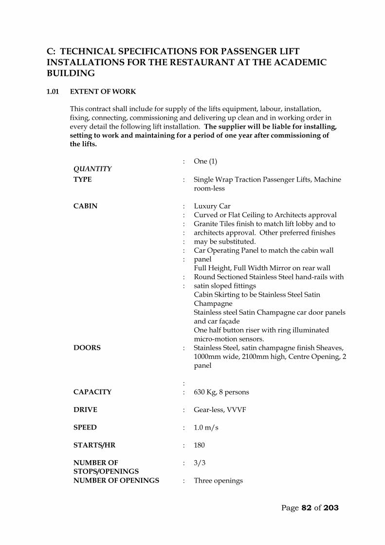
Page 82 of 203
C: TECHNICAL SPECIFICATIONS FOR PASSENGER LIFT INSTALLATIONS FOR THE RESTAURANT AT THE ACADEMIC BUILDING 1.01 EXTENT OF WORK This contract shall include for supply of the lifts equipment, labour, installation,
fixing, connecting, commissioning and delivering up clean and in working order in every detail the following lift installation. The supplier will be liable for installing, setting to work and maintaining for a period of one year after commissioning of the lifts.
QUANTITY : One (1)
TYPE : Single Wrap Traction Passenger Lifts, Machine room-less
CABIN : : : : : : : : :
Luxury Car Curved or Flat Ceiling to Architects approval Granite Tiles finish to match lift lobby and to architects approval. Other preferred finishes may be substituted. Car Operating Panel to match the cabin wall panel Full Height, Full Width Mirror on rear wall Round Sectioned Stainless Steel hand-rails with satin sloped fittings Cabin Skirting to be Stainless Steel Satin Champagne Stainless steel Satin Champagne car door panels and car façade One half button riser with ring illuminated micro-motion sensors.
DOORS : Stainless Steel, satin champagne finish Sheaves, 1000mm wide, 2100mm high, Centre Opening, 2 panel
: CAPACITY : 630 Kg, 8 persons
DRIVE : Gear-less, VVVF
SPEED : 1.0 m/s
STARTS/HR : 180
NUMBER OF STOPS/OPENINGS
: 3/3
NUMBER OF OPENINGS : Three openings
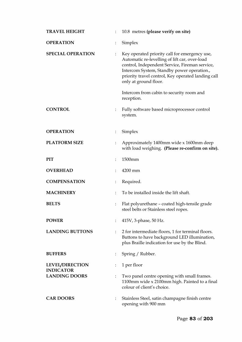
Page 83 of 203
TRAVEL HEIGHT : 10.8 metres (please verify on site)
OPERATION : Simplex
SPECIAL OPERATION : Key operated priority call for emergency use, Automatic re-levelling of lift car, over-load control, Independent Service, Fireman service, Intercom System, Standby power operation., priority travel control, Key operated landing call only at ground floor. Intercom from cabin to security room and reception.
CONTROL : Fully software based microprocessor control system.
OPERATION : Simplex
PLATFORM SIZE : Approximately 1400mm wide x 1600mm deep
with load weighing. (Please re-confirm on site).
PIT : 1500mm
OVERHEAD : 4200 mm
COMPENSATION : Required.
MACHINERY : To be installed inside the lift shaft.
BELTS : Flat polyurethane – coated high-tensile grade steel belts or Stainless steel ropes.
POWER : 415V, 3-phase, 50 Hz.
LANDING BUTTONS : 2 for intermediate floors, 1 for terminal floors. Buttons to have background LED illumination, plus Braille indication for use by the Blind.
BUFFERS : Spring / Rubber.
LEVEL/DIRECTION INDICATOR
: 1 per floor
LANDING DOORS : Two panel centre opening with small frames. 1100mm wide x 2100mm high. Painted to a final colour of client’s choice.
CAR DOORS : Stainless Steel, satin champagne finish centre opening with 900 mm
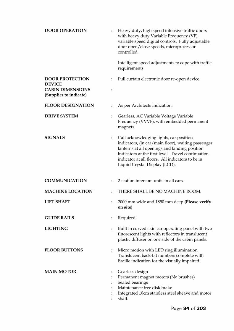
Page 84 of 203
DOOR OPERATION : Heavy duty, high speed intensive traffic doors with heavy duty Variable Frequency (VF), variable speed digital controls. Fully adjustable door open/close speeds, microprocessor controlled. Intelligent speed adjustments to cope with traffic requirements.
DOOR PROTECTION DEVICE
: Full curtain electronic door re-open device.
CABIN DIMENSIONS (Supplier to indicate)
:
FLOOR DESIGNATION : As per Architects indication.
DRIVE SYSTEM : Gearless, AC Variable Voltage Variable Frequency (VVVF), with embedded permanent magnets.
SIGNALS : Call acknowledging lights, car position indicators, (in car/main floor), waiting passenger lanterns at all openings and landing position indicators at the first level. Travel continuation indicator at all floors. All indicators to be in Liquid Crystal Display (LCD).
COMMUNICATION : 2-station intercom units in all cars.
MACHINE LOCATION
: THERE SHALL BE NO MACHINE ROOM.
LIFT SHAFT : 2000 mm wide and 1850 mm deep (Please verify on site)
GUIDE RAILS : Required.
LIGHTING : Built in curved skin car operating panel with two fluorescent lights with reflectors in translucent plastic diffuser on one side of the cabin panels.
FLOOR BUTTONS : Micro motion with LED ring illumination. Translucent back-bit numbers complete with Braille indication for the visually impaired.
MAIN MOTOR : : : : : :
Gearless design Permanent magnet motors (No brushes) Sealed bearings Maintenance free disk brake Integrated 10cm stainless steel sheave and motor shaft.
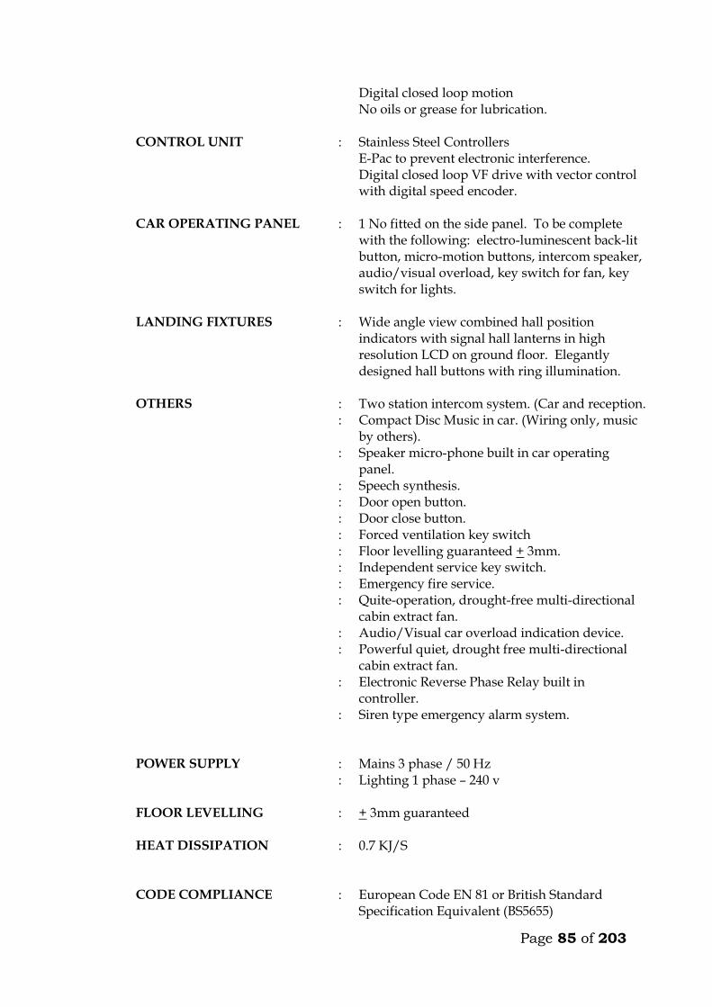
Page 85 of 203
Digital closed loop motion No oils or grease for lubrication.
CONTROL UNIT : Stainless Steel Controllers E-Pac to prevent electronic interference. Digital closed loop VF drive with vector control with digital speed encoder.
CAR OPERATING PANEL : 1 No fitted on the side panel. To be complete with the following: electro-luminescent back-lit button, micro-motion buttons, intercom speaker, audio/visual overload, key switch for fan, key switch for lights.
LANDING FIXTURES : Wide angle view combined hall position indicators with signal hall lanterns in high resolution LCD on ground floor. Elegantly designed hall buttons with ring illumination.
OTHERS : Two station intercom system. (Car and reception. : Compact Disc Music in car. (Wiring only, music
by others). : Speaker micro-phone built in car operating
panel. : Speech synthesis. : Door open button. : Door close button. : Forced ventilation key switch : Floor levelling guaranteed + 3mm. : Independent service key switch. : Emergency fire service. : Quite-operation, drought-free multi-directional
cabin extract fan. : Audio/Visual car overload indication device. : Powerful quiet, drought free multi-directional
cabin extract fan. : Electronic Reverse Phase Relay built in
controller. : Siren type emergency alarm system.
POWER SUPPLY : :
Mains 3 phase / 50 Hz Lighting 1 phase – 240 v
FLOOR LEVELLING : + 3mm guaranteed
HEAT DISSIPATION : 0.7 KJ/S
CODE COMPLIANCE : European Code EN 81 or British Standard Specification Equivalent (BS5655)
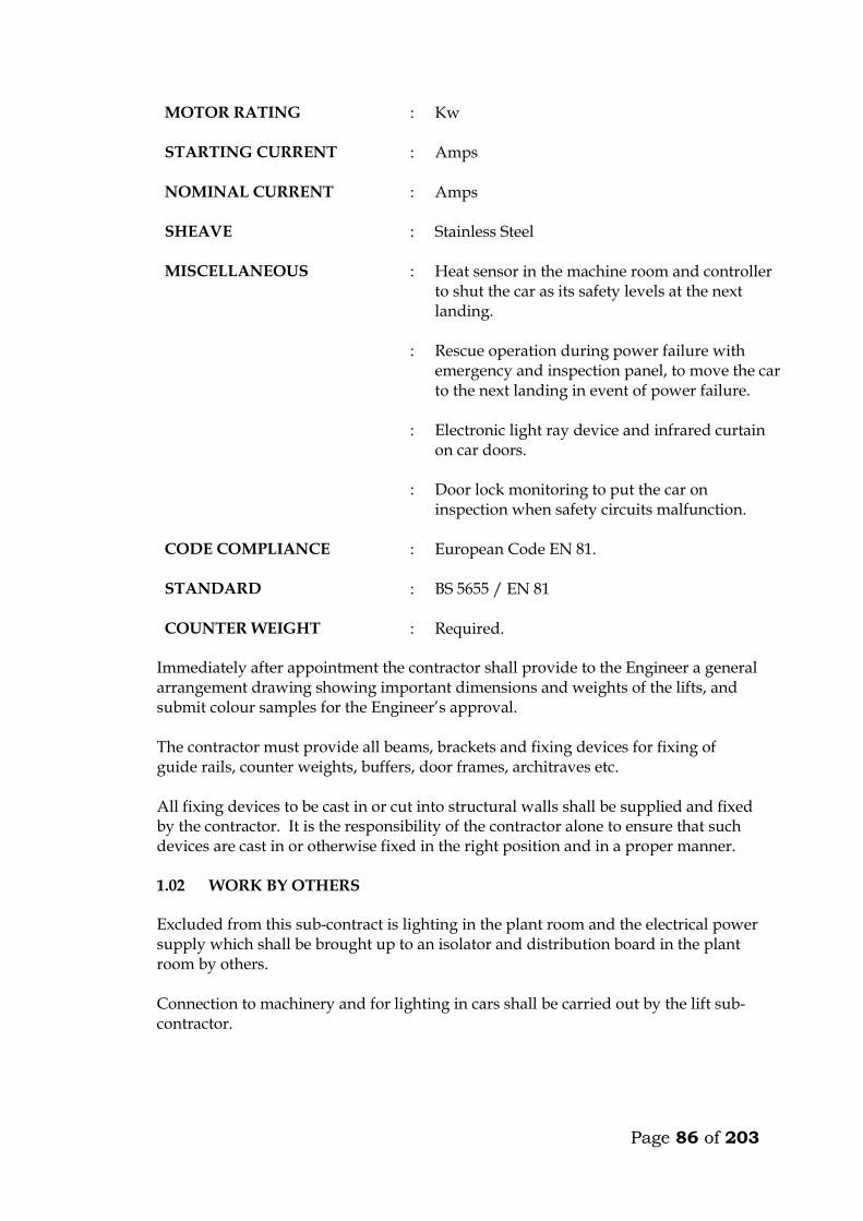
Page 86 of 203
MOTOR RATING : Kw
STARTING CURRENT : Amps
NOMINAL CURRENT : Amps
SHEAVE : Stainless Steel
MISCELLANEOUS : Heat sensor in the machine room and controller to shut the car as its safety levels at the next landing.
: Rescue operation during power failure with emergency and inspection panel, to move the car to the next landing in event of power failure.
: Electronic light ray device and infrared curtain on car doors.
: Door lock monitoring to put the car on inspection when safety circuits malfunction.
CODE COMPLIANCE : European Code EN 81.
STANDARD : BS 5655 / EN 81
COUNTER WEIGHT : Required. Immediately after appointment the contractor shall provide to the Engineer a general
arrangement drawing showing important dimensions and weights of the lifts, and submit colour samples for the Engineer’s approval.
The contractor must provide all beams, brackets and fixing devices for fixing of
guide rails, counter weights, buffers, door frames, architraves etc. All fixing devices to be cast in or cut into structural walls shall be supplied and fixed
by the contractor. It is the responsibility of the contractor alone to ensure that such devices are cast in or otherwise fixed in the right position and in a proper manner.
1.02 WORK BY OTHERS
Excluded from this sub-contract is lighting in the plant room and the electrical power supply which shall be brought up to an isolator and distribution board in the plant room by others. Connection to machinery and for lighting in cars shall be carried out by the lift sub-contractor.
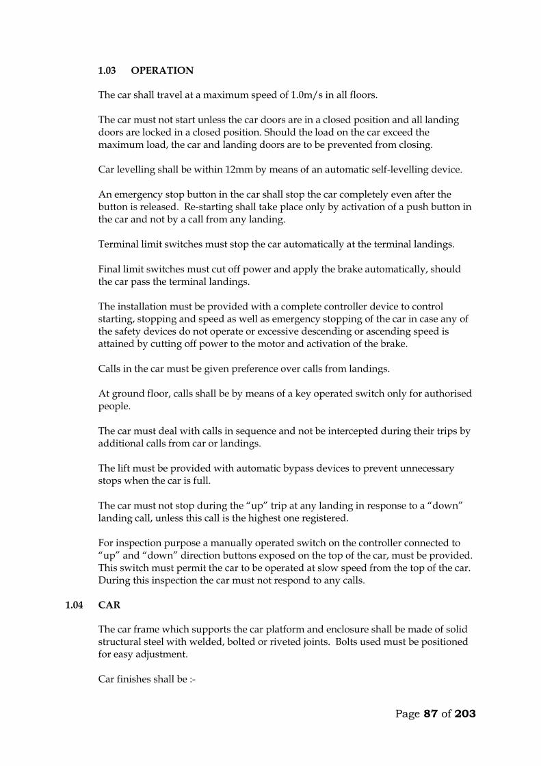
Page 87 of 203
1.03 OPERATION
The car shall travel at a maximum speed of 1.0m/s in all floors. The car must not start unless the car doors are in a closed position and all landing doors are locked in a closed position. Should the load on the car exceed the maximum load, the car and landing doors are to be prevented from closing. Car levelling shall be within 12mm by means of an automatic self-levelling device. An emergency stop button in the car shall stop the car completely even after the button is released. Re-starting shall take place only by activation of a push button in the car and not by a call from any landing. Terminal limit switches must stop the car automatically at the terminal landings. Final limit switches must cut off power and apply the brake automatically, should the car pass the terminal landings. The installation must be provided with a complete controller device to control starting, stopping and speed as well as emergency stopping of the car in case any of the safety devices do not operate or excessive descending or ascending speed is attained by cutting off power to the motor and activation of the brake. Calls in the car must be given preference over calls from landings. At ground floor, calls shall be by means of a key operated switch only for authorised people. The car must deal with calls in sequence and not be intercepted during their trips by additional calls from car or landings. The lift must be provided with automatic bypass devices to prevent unnecessary stops when the car is full. The car must not stop during the “up” trip at any landing in response to a “down” landing call, unless this call is the highest one registered. For inspection purpose a manually operated switch on the controller connected to “up” and “down” direction buttons exposed on the top of the car, must be provided. This switch must permit the car to be operated at slow speed from the top of the car. During this inspection the car must not respond to any calls.
1.04 CAR The car frame which supports the car platform and enclosure shall be made of solid
structural steel with welded, bolted or riveted joints. Bolts used must be positioned for easy adjustment. Car finishes shall be :-
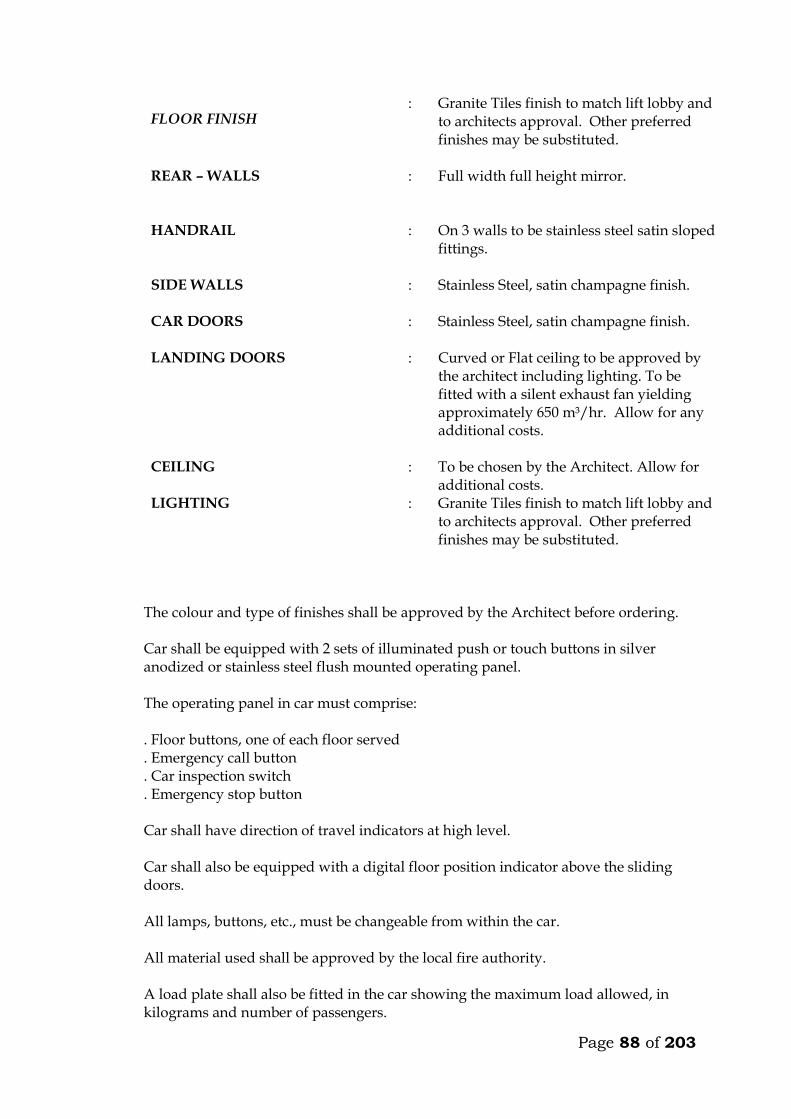
Page 88 of 203
FLOOR FINISH : Granite Tiles finish to match lift lobby and
to architects approval. Other preferred finishes may be substituted.
REAR – WALLS : Full width full height mirror.
HANDRAIL : On 3 walls to be stainless steel satin sloped fittings.
SIDE WALLS : Stainless Steel, satin champagne finish.
CAR DOORS : Stainless Steel, satin champagne finish.
LANDING DOORS : Curved or Flat ceiling to be approved by the architect including lighting. To be fitted with a silent exhaust fan yielding approximately 650 m³/hr. Allow for any additional costs.
CEILING : To be chosen by the Architect. Allow for additional costs.
LIGHTING : Granite Tiles finish to match lift lobby and to architects approval. Other preferred finishes may be substituted.
The colour and type of finishes shall be approved by the Architect before ordering. Car shall be equipped with 2 sets of illuminated push or touch buttons in silver
anodized or stainless steel flush mounted operating panel. The operating panel in car must comprise: . Floor buttons, one of each floor served . Emergency call button . Car inspection switch . Emergency stop button Car shall have direction of travel indicators at high level. Car shall also be equipped with a digital floor position indicator above the sliding
doors. All lamps, buttons, etc., must be changeable from within the car. All material used shall be approved by the local fire authority. A load plate shall also be fitted in the car showing the maximum load allowed, in
kilograms and number of passengers.
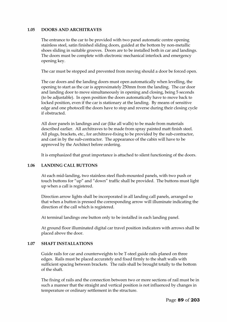
Page 89 of 203
1.05 DOORS AND ARCHITRAVES The entrance to the car to be provided with two panel automatic centre opening
stainless steel, satin finished sliding doors, guided at the bottom by non-metallic shoes sliding in suitable grooves. Doors are to be installed both in car and landings. The doors must be complete with electronic mechanical interlock and emergency opening key.
The car must be stopped and prevented from moving should a door be forced open. The car doors and the landing doors must open automatically when levelling, the
opening to start as the car is approximately 250mm from the landing. The car door and landing door to move simultaneously in opening and closing, being 5 seconds (to be adjustable). In open position the doors automatically have to move back to locked position, even if the car is stationary at the landing. By means of sensitive edge and one photocell the doors have to stop and reverse during their closing cycle if obstructed.
All door panels in landings and car (like all walls) to be made from materials
described earlier. All architraves to be made from spray painted matt finish steel. All plugs, brackets, etc., for architrave-fixing to be provided by the sub-contractor, and cast in by the sub-contractor. The appearance of the cabin will have to be approved by the Architect before ordering.
It is emphasized that great importance is attached to silent functioning of the doors.
1.06 LANDING CALL BUTTONS At each mid-landing, two stainless steel flush-mounted panels, with two push or
touch buttons for “up” and “down” traffic shall be provided. The buttons must light up when a call is registered.
Direction arrow lights shall be incorporated in all landing call panels, arranged so
that when a button is pressed the corresponding arrow will illuminate indicating the direction of the call which is registered.
At terminal landings one button only to be installed in each landing panel. At ground floor illuminated digital car travel position indicators with arrows shall be
placed above the door. 1.07 SHAFT INSTALLATIONS Guide rails for car and counterweights to be T-steel guide rails planed on three
edges. Rails must be placed accurately and fixed firmly to the shaft walls with sufficient spacing between brackets. The rails shall be brought totally to the bottom of the shaft.
The fixing of rails and the connection between two or more sections of rail must be in
such a manner that the straight and vertical position is not influenced by changes in temperature or ordinary settlement in the structure.
Page 90 of 203
Guide rails for the car to be either rubber roller guides or Telfon (Tufnol). Roller and shoes shall be renewable.
Buffer must be provided to bring the car counterweight to rest at the extreme limits
of travel, should the car for any reason pass the limit switches. The guide rails, roller shoes, buffers, counter-weight all to be provided and installed
by the Sub-contractor. 1.08 LIFTING MACHINERY
The machine shall be gearless, single wrap traction type, mounted on steel beams fitted on the shaft walls. The beams to be as per structural engineers details. The following information on the machinery must accompany the tender. Make Size, h.p. Voltage, V Power consumption at full load, KW Revolutions per minute, r.p.m. Full load current, A Starting current, A Duration of starting current, sec
Power factor, cos Acceleration time, sec Retardation time, sec The motor must be provided with overload and phase failure cutout devices. The control system to be fitted with a special batter/charger to enable technicians to move cabin to the nearest level to release trapped passengers in case of power failure. The system must prevent engaging of the turning device, until the power supply for the motor is switched off. The aggregate must be dimensioned for the full load in continuous operation and for a temporary overload of 10%. The sub-contractor must provide information on the highest permissible operating temperature for optional functioning of the lift, and about the heat produced by the entire installation.
1.09 ROPES AND SHEAVES The lift shall be provided with durable, flat polyurethane-coated high-tensile steel
belts. Ropes maybe substituted but subject to engineers approval. The sheaves shall be of ample diameter for ropes used. Sheaves shall be fixed by
means of iron beams which are supplied and installed by the sub-contractor. Beams must be sound insulated from structural parts.
Page 91 of 203
1.10 ELECTRICAL INSTALLATION All motors and switchgear shall be rated for operation at 240V/415V, 50 cycles.
Relays and components must be tropicalised. The installation must comply with the IEE Regulations. All wiring shall be carried
out in a neat and orderly manner. Cables run on walls or ceilings to be in straight line and right angle bends enclosed in steel ducting.
Connections to equipment more than 400mm from wall shall be run from the wall in
conduit cast in the floor to a connector box fixed upright adjacent to the equipment and through flexible conduit to the equipment.
All electrical switchgear must be clearly labelled. 1.11 ALARM
An alarm button in the car shall simultaneously activate a bell situated on the car and bell positioned at the security station near the lift lobby at ground floor. The bells shall be supplied with power from a rechargeable dry cell battery supplied by sub-contractor. All wiring and installation of the alarm system shall be done by the sub-contractor.
Page 92 of 203
TECHNICAL DETAILS OF LIFTS OFFERED BY THE TENDERER 5. Lifting Machinery
a) Make b) Size, h.p. c) Power consumption at full load, KW d) Revolutions per minute, r.p.m. e) Full load current, A f) Starting current, A g) Duration of starting current, sec
h) Power factor, cos i) Acceleration time, sec j) Retardation time, sec
6. Delivery Details
Time in weeks from acceptance of tender to delivery of all equipment on site ________ Weeks.
Time in weeks from acceptance of tender to installation and commissioning _________ Weeks. 3. Deviations from the Specification
The Tenderer shall give below details of any Specification, or any deviations, omissions, additions of alternatives in respect of the lifts which he is offering. If none, write None.

Page 93 of 203
MAINTENANCE CONTRACT The Tenderer shall insert in this section the cost of a fully comprehensive Maintenance Contract after one of the initial 12 months maintenance or defects liability period. The sum to be inclusive of regular monthly inspection and breakdown service, and shall include for all tools, parts replacement and service material such as oils, lubricants, etc. ITEM KSHS. Annual Maintenance cost for 1 No. lifts as described
in the following pages inclusive of all spares and 24 hour call services (start date assumed end of building contract). _______________ WARRANTY The warranty period for the equipment and all the associated accessories shall be _______________ months from the date of commissioning. (A minimum of 12 months will be allowed). FOREIGN CURRENCY State the foreign currency applied and the exchange rate to the Kenya Shilling. 1 ____________________ (Foreign Currency) = _____________________ KSh.
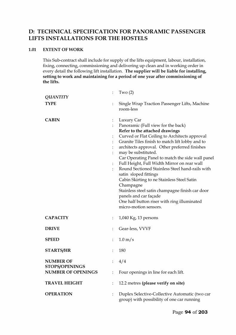
Page 94 of 203
D: TECHNICAL SPECIFICATION FOR PANORAMIC PASSENGER LIFTS INSTALLATIONS FOR THE HOSTELS 1.01 EXTENT OF WORK This Sub-contract shall include for supply of the lifts equipment, labour, installation,
fixing, connecting, commissioning and delivering up clean and in working order in every detail the following lift installation. The supplier will be liable for installing, setting to work and maintaining for a period of one year after commissioning of the lifts.
QUANTITY : Two (2)
TYPE : Single Wrap Traction Passenger Lifts, Machine room-less
CABIN : : : : : : : :
Luxury Car Panoramic (Full view for the back) Refer to the attached drawings Curved or Flat Ceiling to Architects approval Granite Tiles finish to match lift lobby and to architects approval. Other preferred finishes may be substituted. Car Operating Panel to match the side wall panel Full Height, Full Width Mirror on rear wall Round Sectioned Stainless Steel hand-rails with satin sloped fittings Cabin Skirting to ne Stainless Steel Satin Champagne Stainless steel satin champagne finish car door panels and car façade One half button riser with ring illuminated micro-motion sensors.
CAPACITY : 1,040 Kg, 13 persons
DRIVE : Gear-less, VVVF
SPEED : 1.0 m/s
STARTS/HR : 180
NUMBER OF STOPS/OPENINGS
: 4/4
NUMBER OF OPENINGS : Four openings in line for each lift.
TRAVEL HEIGHT : 12.2 metres (please verify on site)
OPERATION : Duplex Selective-Collective Automatic (two car group) with possibility of one car running
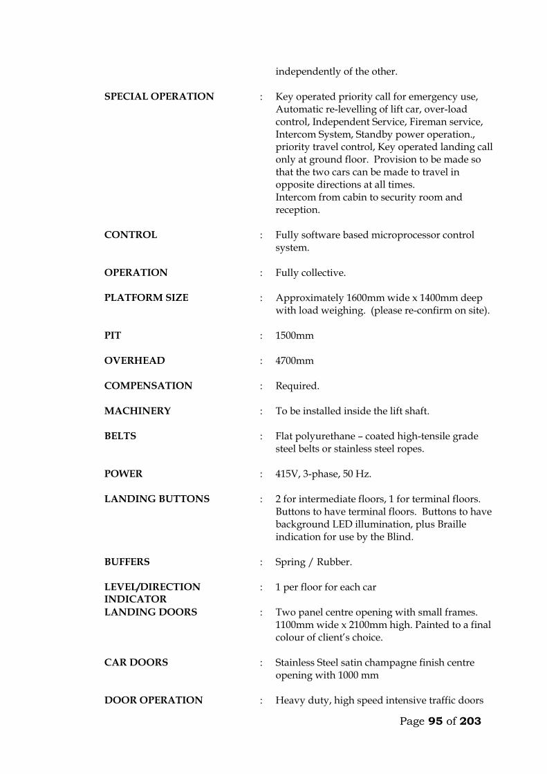
Page 95 of 203
independently of the other.
SPECIAL OPERATION : Key operated priority call for emergency use, Automatic re-levelling of lift car, over-load control, Independent Service, Fireman service, Intercom System, Standby power operation., priority travel control, Key operated landing call only at ground floor. Provision to be made so that the two cars can be made to travel in opposite directions at all times. Intercom from cabin to security room and reception.
CONTROL : Fully software based microprocessor control system.
OPERATION : Fully collective.
PLATFORM SIZE : Approximately 1600mm wide x 1400mm deep with load weighing. (please re-confirm on site).
PIT : 1500mm
OVERHEAD : 4700mm
COMPENSATION : Required.
MACHINERY : To be installed inside the lift shaft.
BELTS : Flat polyurethane – coated high-tensile grade steel belts or stainless steel ropes.
POWER : 415V, 3-phase, 50 Hz.
LANDING BUTTONS : 2 for intermediate floors, 1 for terminal floors. Buttons to have terminal floors. Buttons to have background LED illumination, plus Braille indication for use by the Blind.
BUFFERS : Spring / Rubber.
LEVEL/DIRECTION INDICATOR
: 1 per floor for each car
LANDING DOORS : Two panel centre opening with small frames. 1100mm wide x 2100mm high. Painted to a final colour of client’s choice.
CAR DOORS : Stainless Steel satin champagne finish centre opening with 1000 mm
DOOR OPERATION : Heavy duty, high speed intensive traffic doors
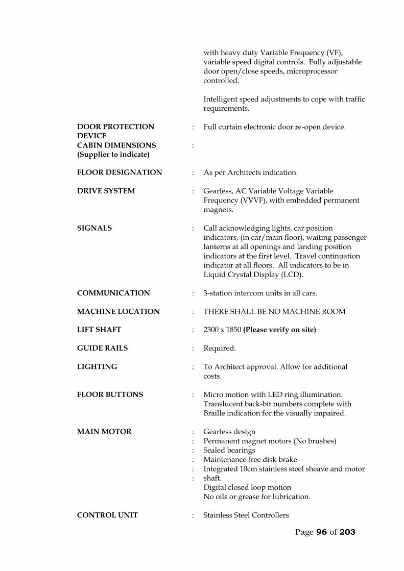
Page 96 of 203
with heavy duty Variable Frequency (VF), variable speed digital controls. Fully adjustable door open/close speeds, microprocessor controlled. Intelligent speed adjustments to cope with traffic requirements.
DOOR PROTECTION DEVICE
: Full curtain electronic door re-open device.
CABIN DIMENSIONS (Supplier to indicate)
:
FLOOR DESIGNATION : As per Architects indication.
DRIVE SYSTEM : Gearless, AC Variable Voltage Variable Frequency (VVVF), with embedded permanent magnets.
SIGNALS : Call acknowledging lights, car position indicators, (in car/main floor), waiting passenger lanterns at all openings and landing position indicators at the first level. Travel continuation indicator at all floors. All indicators to be in Liquid Crystal Display (LCD).
COMMUNICATION : 3-station intercom units in all cars.
MACHINE LOCATION
: THERE SHALL BE NO MACHINE ROOM
LIFT SHAFT : 2300 x 1850 (Please verify on site)
GUIDE RAILS : Required.
LIGHTING : To Architect approval. Allow for additional costs.
FLOOR BUTTONS : Micro motion with LED ring illumination. Translucent back-bit numbers complete with Braille indication for the visually impaired.
MAIN MOTOR : : : : : :
Gearless design Permanent magnet motors (No brushes) Sealed bearings Maintenance free disk brake Integrated 10cm stainless steel sheave and motor shaft. Digital closed loop motion No oils or grease for lubrication.
CONTROL UNIT : Stainless Steel Controllers
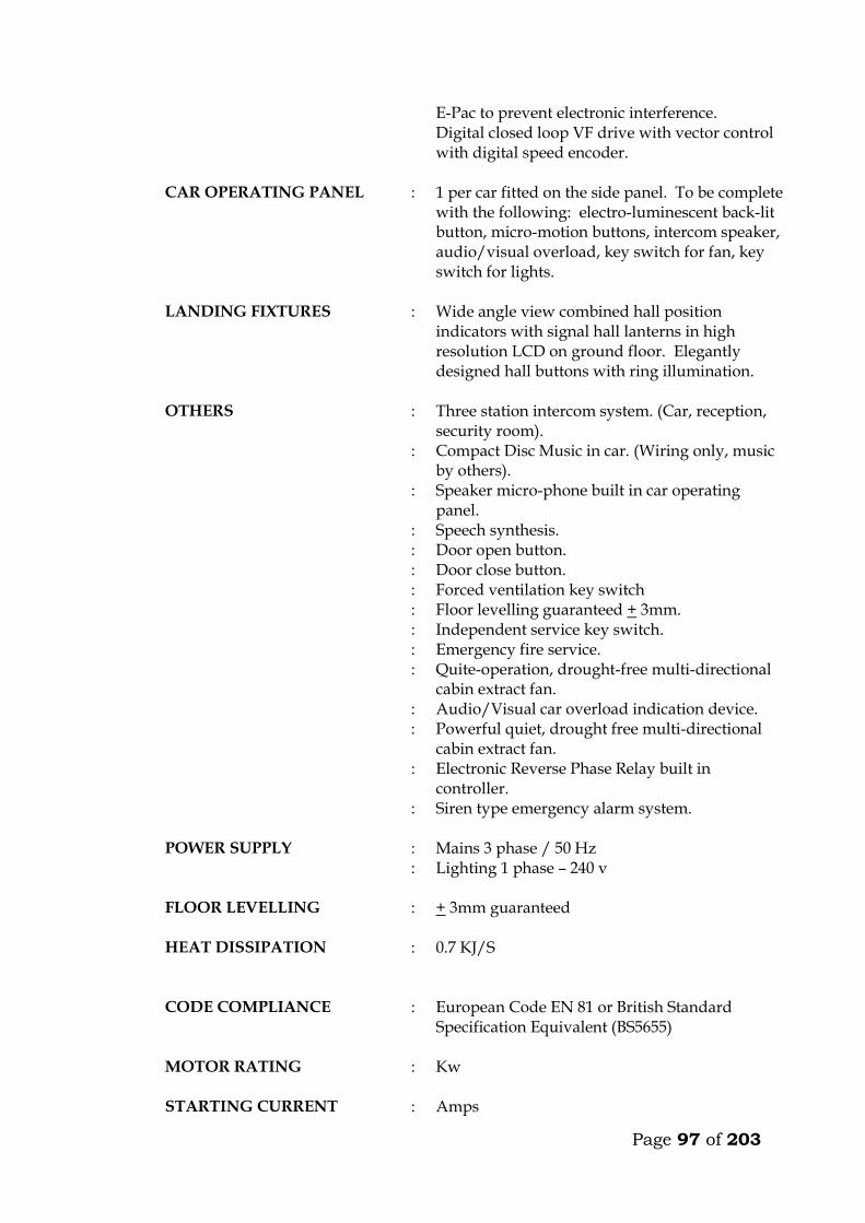
Page 97 of 203
E-Pac to prevent electronic interference. Digital closed loop VF drive with vector control with digital speed encoder.
CAR OPERATING PANEL : 1 per car fitted on the side panel. To be complete with the following: electro-luminescent back-lit button, micro-motion buttons, intercom speaker, audio/visual overload, key switch for fan, key switch for lights.
LANDING FIXTURES : Wide angle view combined hall position indicators with signal hall lanterns in high resolution LCD on ground floor. Elegantly designed hall buttons with ring illumination.
OTHERS : Three station intercom system. (Car, reception, security room).
: Compact Disc Music in car. (Wiring only, music by others).
: Speaker micro-phone built in car operating panel.
: Speech synthesis. : Door open button. : Door close button. : Forced ventilation key switch : Floor levelling guaranteed + 3mm. : Independent service key switch. : Emergency fire service. : Quite-operation, drought-free multi-directional
cabin extract fan. : Audio/Visual car overload indication device. : Powerful quiet, drought free multi-directional
cabin extract fan. : Electronic Reverse Phase Relay built in
controller. : Siren type emergency alarm system.
POWER SUPPLY :
: Mains 3 phase / 50 Hz Lighting 1 phase – 240 v
FLOOR LEVELLING : + 3mm guaranteed
HEAT DISSIPATION : 0.7 KJ/S
CODE COMPLIANCE : European Code EN 81 or British Standard Specification Equivalent (BS5655)
MOTOR RATING : Kw
STARTING CURRENT : Amps
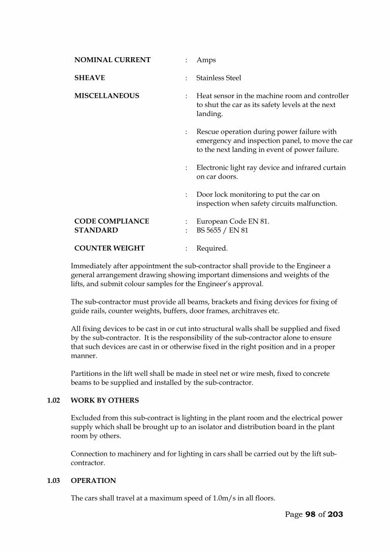
Page 98 of 203
NOMINAL CURRENT : Amps
SHEAVE : Stainless Steel
MISCELLANEOUS : Heat sensor in the machine room and controller
to shut the car as its safety levels at the next landing.
: Rescue operation during power failure with emergency and inspection panel, to move the car to the next landing in event of power failure.
: Electronic light ray device and infrared curtain on car doors.
: Door lock monitoring to put the car on inspection when safety circuits malfunction.
CODE COMPLIANCE : European Code EN 81. STANDARD : BS 5655 / EN 81
COUNTER WEIGHT : Required.
Immediately after appointment the sub-contractor shall provide to the Engineer a
general arrangement drawing showing important dimensions and weights of the lifts, and submit colour samples for the Engineer’s approval.
The sub-contractor must provide all beams, brackets and fixing devices for fixing of
guide rails, counter weights, buffers, door frames, architraves etc. All fixing devices to be cast in or cut into structural walls shall be supplied and fixed
by the sub-contractor. It is the responsibility of the sub-contractor alone to ensure that such devices are cast in or otherwise fixed in the right position and in a proper manner.
Partitions in the lift well shall be made in steel net or wire mesh, fixed to concrete
beams to be supplied and installed by the sub-contractor. 1.02 WORK BY OTHERS
Excluded from this sub-contract is lighting in the plant room and the electrical power supply which shall be brought up to an isolator and distribution board in the plant room by others. Connection to machinery and for lighting in cars shall be carried out by the lift sub-contractor.
1.03 OPERATION
The cars shall travel at a maximum speed of 1.0m/s in all floors.
Page 99 of 203
The car must not start unless the car doors are in a closed position and all landing doors are locked in a closed position. Should the load on the car exceed the maximum load, the car and landing doors are to be prevented from closing. Car levelling shall be within 12mm by means of an automatic self-levelling device. An emergency stop button in the car shall stop the car completely even after the button is released. Re-starting shall take place only by activation of a push button in the car and not by a call from any landing. Terminal limit switches must stop the car automatically at the terminal landings. Final limit switches must cut off power and apply the brake automatically, should the car pass the terminal landings. The installation must be provided with a complete controller device to control starting, stopping and speed as well as emergency stopping of the car in case any of the safety devices do not operate or excessive descending or ascending speed is attained by cutting off power to the motor and activation of the brake. Calls in the car must be given preference over calls from landings. At ground floor, calls shall be by means of a key operated switch only for authorised people. The cars must deal with calls in sequence and not be intercepted during their trips by additional calls from cars or landings. The lifts must be provided with automatic bypass devices to prevent unnecessary stops when the cars are full. If the cars are idle and a landing button is pressed, the car positioned nearest to the pressed button has to go to the landing. The car must not stop during the “up” trip at any landing in response to a “down” landing call, unless this call is the highest one registered. When the cars at the same time are “up” trip or “down” trip, only the leading car must stop for landing calls. If one of the cars is out of operation the other car has to answer all calls aforesaid. The operation is still to be collective. For inspection purpose a manually operated switch on the controller connected to “up” and “down” direction buttons exposed on the top of the car, must be provided. This switch must permit the car to be operated at slow speed from the top of the car. During this inspection the car must not respond to any calls.
Page 100 of 203
Provision to be made in the controls so that the cars can travel permanently in opposite directions when required.
1.04 CARS The car frame which supports the car platform and enclosure shall be made of solid
structural steel with welded, bolted or riveted joints. Bolts used must be positioned for easy adjustment. Car finishes shall be :-
FLOOR FINISH : Granite Tiles finish to match lift lobby and
to architects approval. Other preferred finishes may be substituted.
REAR – WALLS : Full View (Panoramic).
HANDRAIL : On 3 walls to be stainless steel satin sloped fittings.
SIDE WALLS : Stainless steel champagne
CAR DOORS : Stainless Steel, satin champagne finish.
LANDING DOORS : Stainless Steel, satin finish.
CEILING : Curved or Flat ceiling to be approved by the architect including lighting. To be fitted with a silent exhaust fan yielding approximately 650 m³/hr. Allow for any additional costs.
LIGHTING : To be chosen by the Architect. Allow for additional costs.
The colour and type of finishes shall be approved by the Architect before ordering. Each car shall be equipped with 2 sets of illuminated push or touch buttons in silver
anodized or stainless steel flush mounted operating panels. Two car operating panels shall be provided in each car.
The operating panels in all cars must comprise : . Floor buttons, one of each floor served . Emergency call button . Car inspection switch . Emergency stop button Each car shall have direction of travel indicators at high level opposite doors.
Page 101 of 203
Each car shall also be equipped with a digital floor position indicator above the
sliding doors. All lamps, buttons, etc., must be changeable from within the car. All material used shall be approved by the local fire authority. A load plate shall also be fitted in the car showing the maximum load allowed, in
kilograms and number of passengers. 1.05 DOORS AND ARCHITRAVES The entrance to the car to be provided with two panel automatic centre opening
stainless steel, satin finished sliding doors, guided at the bottom by non-metallic shoes sliding in suitable grooves. Doors are to be installed both in car and landings. The doors must be complete with electronic mechanical interlock and emergency opening key.
The car must be stopped and prevented from moving should a door be forced open. The car doors and the landing doors must open automatically when levelling, the
opening to start as the car is approximately 250mm from the landing. The car door and landing door to move simultaneously in opening and closing, being 5 seconds (to be adjustable). In open position the doors automatically have to move back to locked position, even if the car is stationary at the landing. By means of sensitive edge and one photocell the doors have to stop and reverse during their closing cycle if obstructed.
All door panels in landings and cars (like all walls) to be made from materials
described earlier. All architraves to be made from spray painted matt finish steel. All plugs, brackets, etc., for architrave-fixing to be provided by the sub-contractor, and cast in by the sub-contractor. The appearance of the cabin will have to be approved by the Architect before ordering.
It is emphasized that great importance is attached to silent functioning of the doors.
1.06 LANDING CALL BUTTONS At each mid-landing, two stainless steel flush-mounted panels, per car, with two
push or touch buttons for “up” and “down” traffic shall be provided between the landing doors. The buttons must light up when a call is registered.
Direction arrow lights shall be incorporated in all landing call panels, arranged so
that when a button is pressed the corresponding arrow will illuminate indicating the direction of the call which is registered.
At terminal landings one button only to be installed in each landing panel. At ground floor two illuminated digital car travel position indicators with arrows
shall be placed, one above each door.
Page 102 of 203
1.07 SHAFT INSTALLATIONS Guide rails for cars and counterweights to be T-steel guide rails planed on three
edges. Rails must be placed accurately and fixed firmly to the shaft walls with sufficient spacing between brackets. The rails shall be brought totally to the bottom of the shaft.
The fixing of rails and the connection between two or more sections of rail must be in
such a manner that the straight and vertical position is not influenced by changes in temperature or ordinary settlement in the structure.
Guide rails for the car to be either rubber roller guides or Telfon (Tufnol). Roller and
shoes shall be renewable. Buffer must be provided to bring the car counterweight to rest at the extreme limits
of travel, should the car for any reason pass the limit switches. The guide rails, roller shoes, buffers, counter-weight all to be provided and installed
by the Sub-contractor. 1.08 LIFTING MACHINERY
The machine shall be gearless, single wrap traction type, mounted on steel beams fitted on the shaft walls. The beams to be as per structural engineers details. The following information on the machinery must accompany the tender. Make Size, h.p. Voltage, V Power consumption at full load, KW Revolutions per minute, r.p.m. Full load current, A Starting current, A Duration of starting current, sec
Power factor, cos Acceleration time, sec Retardation time, sec The motor must be provided with overload and phase failure cutout devices. The control system to be fitted with a special batter/charger to enable technicians to move cabin to the nearest level to release trapped passengers in case of power failure. The system must prevent engaging of the turning device, until the power supply for the motor is switched off. The aggregate must be dimensioned for the full load in continuous operation and for a temporary overload of 10%. The sub-contractor must provide information on the highest permissible operating temperature for optional functioning of the lift, and about the heat produced by the entire installation.
Page 103 of 203
1.09 ROPES AND SHEAVES The lifts shall be provided with durable, flat polyurethane-coated high-tensile steel
belts. Ropes maybe substituted but subject to engineers approval. The sheaves shall be of ample diameter for ropes used. Sheaves shall be fixed by
means of iron beams which are supplied and installed by the sub-contractor. Beams must be sound insulated from structural parts.
1.10 ELECTRICAL INSTALLATION All motors and switchgear shall be rated for operation at 240V/415V, 50 cycles.
Relays and components must be tropicalised. The installation must comply with the IEE Regulations. All wiring shall be carried
out in a neat and orderly manner. Cables run on walls or ceilings to be in straight line and right angle bends enclosed in steel ducting.
Connections to equipment more than 400mm from wall shall be run from the wall in
conduit cast in the floor to a connector box fixed upright adjacent to the equipment and through flexible conduit to the equipment.
All electrical switchgear must be clearly labelled. 1.11 ALARM
An alarm button in the car shall simultaneously activate a bell situated on the car and bell positioned at the security station near the lift lobby at ground floor. The bells shall be supplied with power from a rechargeable dry cell battery supplied by sub-contractor. All wiring and installation of the alarm system shall be done by the sub-contractor.
1.12 CONTROL AND DISPLAY SYSTEM A control and display system shall be provided at the security room. The system, comprising a colour video monitor and keyboard shall indicate real-time elevator status, passenger traffic and demand, etc. It shall also be possible to feed commands to the controller from the keyboard, to adjust operation of the cars and for faults diagnosis.

Page 104 of 203
TECHNICAL DETAILS OF LIFTS OFFERED BY THE TENDERER 7. Lifting Machinery
a) Make b) Size, h.p. c) Power consumption at full load, KW d) Revolutions per minute, r.p.m. e) Full load current, A f) Starting current, A g) Duration of starting current, sec
h) Power factor, cos i) Acceleration time, sec j) Retardation time, sec
8. Delivery Details
Time in weeks from acceptance of tender to delivery of all equipment on site ________ Weeks.
Time in weeks from acceptance of tender to installation and commissioning _________ Weeks. 3. Deviations from the Specification
The Tenderer shall give below details of any Specification, or any deviations, omissions, additions of alternatives in respect of the lifts which he is offering. If none, write None.

Page 105 of 203
MAINTENANCE CONTRACT The Tenderer shall insert in this section the cost of a fully comprehensive Maintenance Contract after one of the initial 12 months maintenance or defects liability period. The sum to be inclusive of regular monthly inspection and breakdown service, and shall include for all tools, parts replacement and service material such as oils, lubricants, etc. ITEM KSHS. Annual Maintenance cost for 2 No. lifts as described
in the following pages inclusive of all spares and 24 hour call services (start date assumed end of building contract). _______________ WARRANTY The warranty period for the equipment and all the associated accessories shall be _______________ months from the date of commissioning. (A minimum of 12 months will be allowed). FOREIGN CURRENCY State the foreign currency applied and the exchange rate to the Kenya Shilling. 1 ____________________ (Foreign Currency) = _____________________ KSh.
Page 106 of 203
E: TECHNICAL SPECIFICATIONS FOR PASSENGER LIFT INSTALLATIONS FOR RECEPTION BUILDING 1.01 EXTENT OF WORK This contract shall include for supply of the lifts equipment, labour, installation,
fixing, connecting, commissioning and delivering up clean and in working order in every detail the following lift installation. The supplier will be liable for installing, setting to work and maintaining for a period of one year after commissioning of the lifts.
QUANTITY : One (1)
TYPE : Single Wrap Traction Passenger Lifts, Machine room-less
CABIN : : : : : : : : :
Luxury Car Curved or Flat Ceiling to Architects approval Granite Tiles finish to match lift lobby and to architects approval. Other preferred finishes may be substituted. Car Operating Panel to match the cabin wall panel Full Height, Full Width Mirror on rear wall Round Sectioned Stainless Steel hand-rails with satin sloped fittings Cabin Skirting to be Stainless Steel Satin Champagne Stainless steel Satin Champagne car door panels and car façade One half button riser with ring illuminated micro-motion sensors.
DOORS : Stainless Steel, satin champagne finish, Sheaves, 1000mm wide, 2100mm high, Centre Opening, 2 panel
CAPACITY : 800 Kg, 10 persons
DRIVE : Gear-less, VVVF
SPEED : 1.0 m/s
STARTS/HR : 180
NUMBER OF STOPS/OPENINGS
: 3/3
NUMBER OF OPENINGS : Three openings
TRAVEL HEIGHT : 12.55 metres (please verify on site)
Page 107 of 203
OPERATION : Simplex
SPECIAL OPERATION : Key operated priority call for emergency use, Automatic re-levelling of lift car, over-load control, Independent Service, Fireman service, Intercom System, Standby power operation., priority travel control, Key operated landing call only at ground floor. Intercom from cabin to security room and reception.
CONTROL : Fully software based microprocessor control system.
OPERATION : Simplex
PLATFORM SIZE : Approximately 1400mm wide x 1600mm deep
with load weighing. (Please re-confirm on site).
PIT : 1500mm
OVERHEAD : 4400 mm
COMPENSATION : Required.
MACHINERY : To be installed inside the lift shaft.
BELTS : Flat polyurethane – coated high-tensile grade steel belts or stainless steel ropes.
POWER : 415V, 3-phase, 50 Hz.
LANDING BUTTONS : 2 for intermediate floors, 1 for terminal floors. Buttons to have background LED illumination, plus Braille indication for use by the Blind.
BUFFERS : Spring / Rubber.
LEVEL/DIRECTION INDICATOR
: 1 per floor
LANDING DOORS : Stainless Steel Two panel centre opening with small frames. 1100mm wide x 2100mm high.
CAR DOORS : Stainless Steel centre opening with 900 mm
DOOR OPERATION : Heavy duty, high speed intensive traffic doors with heavy duty Variable Frequency (VF), variable speed digital controls. Fully adjustable door open/close speeds, microprocessor
Page 108 of 203
controlled. Intelligent speed adjustments to cope with traffic requirements.
DOOR PROTECTION DEVICE
: Full curtain electronic door re-open device.
CABIN DIMENSIONS (Supplier to indicate)
:
FLOOR DESIGNATION : As per Architects indication.
DRIVE SYSTEM : Gearless, AC Variable Voltage Variable Frequency (VVVF), with embedded permanent magnets.
SIGNALS : Call acknowledging lights, car position indicators, (in car/main floor), waiting passenger lanterns at all openings and landing position indicators at the first level. Travel continuation indicator at all floors. All indicators to be in Liquid Crystal Display (LCD).
COMMUNICATION : 2-station intercom units in all cars.
MACHINE LOCATION
: THERE SHALL BE NO MACHINE ROOM.
LIFT SHAFT : 2100 mm wide and 2200 mm deep (please verify on site)
GUIDE RAILS : Required.
LIGHTING : To Architect approval. Allow for additional costs.
FLOOR BUTTONS : Micro motion with LED ring illumination. Translucent back-bit numbers complete with Braille indication for the visually impaired.
MAIN MOTOR : : : : : :
Gearless design Permanent magnet motors (No brushes) Sealed bearings Maintenance free disk brake Integrated 10cm stainless steel sheave and motor shaft. Digital closed loop motion No oils or grease for lubrication.
CONTROL UNIT : Stainless Steel Controllers E-Pac to prevent electronic interference.

Page 109 of 203
Digital closed loop VF drive with vector control with digital speed encoder.
CAR OPERATING PANEL : 1 No fitted on the side panel. To be complete with the following: electro-luminescent back-lit button, micro-motion buttons, intercom speaker, audio/visual overload, key switch for fan, key switch for lights.
LANDING FIXTURES : Wide angle view combined hall position indicators with signal hall lanterns in high resolution LCD on ground floor. Elegantly designed hall buttons with ring illumination.
OTHERS : Two station intercom system. (Car and reception. : Compact Disc Music in car. (Wiring only, music
by others). : Speaker micro-phone built in car operating
panel. : Speech synthesis. : Door open button. : Door close button. : Forced ventilation key switch : Floor levelling guaranteed + 3mm. : Independent service key switch. : Emergency fire service. : Quite-operation, drought-free multi-directional
cabin extract fan. : Audio/Visual car overload indication device. : Powerful quiet, drought free multi-directional
cabin extract fan. : Electronic Reverse Phase Relay built in
controller. : Siren type emergency alarm system.
POWER SUPPLY : :
Mains 3 phase / 50 Hz Lighting 1 phase – 240 v
FLOOR LEVELLING : + 3mm guaranteed
HEAT DISSIPATION : 0.7 KJ/S
CODE COMPLIANCE : European Code EN 81 or British Standard Specification Equivalent (BS5655)
MOTOR RATING : Kw
STARTING CURRENT : Amps
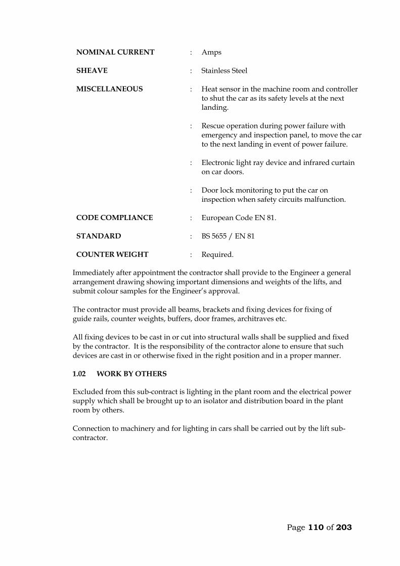
Page 110 of 203
NOMINAL CURRENT : Amps
SHEAVE : Stainless Steel
MISCELLANEOUS : Heat sensor in the machine room and controller to shut the car as its safety levels at the next landing.
: Rescue operation during power failure with emergency and inspection panel, to move the car to the next landing in event of power failure.
: Electronic light ray device and infrared curtain on car doors.
: Door lock monitoring to put the car on inspection when safety circuits malfunction.
CODE COMPLIANCE : European Code EN 81.
STANDARD : BS 5655 / EN 81
COUNTER WEIGHT : Required. Immediately after appointment the contractor shall provide to the Engineer a general
arrangement drawing showing important dimensions and weights of the lifts, and submit colour samples for the Engineer’s approval.
The contractor must provide all beams, brackets and fixing devices for fixing of
guide rails, counter weights, buffers, door frames, architraves etc. All fixing devices to be cast in or cut into structural walls shall be supplied and fixed
by the contractor. It is the responsibility of the contractor alone to ensure that such devices are cast in or otherwise fixed in the right position and in a proper manner.
1.02 WORK BY OTHERS
Excluded from this sub-contract is lighting in the plant room and the electrical power supply which shall be brought up to an isolator and distribution board in the plant room by others. Connection to machinery and for lighting in cars shall be carried out by the lift sub-contractor.

Page 111 of 203
1.03 OPERATION
The car shall travel at a maximum speed of 1.0m/s in all floors. The car must not start unless the car doors are in a closed position and all landing doors are locked in a closed position. Should the load on the car exceed the maximum load, the car and landing doors are to be prevented from closing. Car levelling shall be within 12mm by means of an automatic self-levelling device. An emergency stop button in the car shall stop the car completely even after the button is released. Re-starting shall take place only by activation of a push button in the car and not by a call from any landing. Terminal limit switches must stop the car automatically at the terminal landings. Final limit switches must cut off power and apply the brake automatically, should the car pass the terminal landings. The installation must be provided with a complete controller device to control starting, stopping and speed as well as emergency stopping of the car in case any of the safety devices do not operate or excessive descending or ascending speed is attained by cutting off power to the motor and activation of the brake. Calls in the car must be given preference over calls from landings. At ground floor, calls shall be by means of a key operated switch only for authorised people. The car must deal with calls in sequence and not be intercepted during their trips by additional calls from car or landings. The lift must be provided with automatic bypass devices to prevent unnecessary stops when the car is full. The car must not stop during the “up” trip at any landing in response to a “down” landing call, unless this call is the highest one registered. For inspection purpose a manually operated switch on the controller connected to “up” and “down” direction buttons exposed on the top of the car, must be provided. This switch must permit the car to be operated at slow speed from the top of the car. During this inspection the car must not respond to any calls.
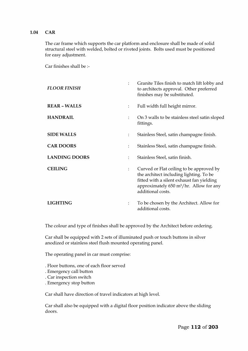
Page 112 of 203
1.04 CAR The car frame which supports the car platform and enclosure shall be made of solid
structural steel with welded, bolted or riveted joints. Bolts used must be positioned for easy adjustment. Car finishes shall be :-
FLOOR FINISH : Granite Tiles finish to match lift lobby and
to architects approval. Other preferred finishes may be substituted.
REAR – WALLS : Full width full height mirror.
HANDRAIL : On 3 walls to be stainless steel satin sloped fittings.
SIDE WALLS : Stainless Steel, satin champagne finish.
CAR DOORS : Stainless Steel, satin champagne finish.
LANDING DOORS : Stainless Steel, satin finish.
CEILING : Curved or Flat ceiling to be approved by the architect including lighting. To be fitted with a silent exhaust fan yielding approximately 650 m³/hr. Allow for any additional costs.
LIGHTING : To be chosen by the Architect. Allow for additional costs.
The colour and type of finishes shall be approved by the Architect before ordering. Car shall be equipped with 2 sets of illuminated push or touch buttons in silver
anodized or stainless steel flush mounted operating panel. The operating panel in car must comprise: . Floor buttons, one of each floor served . Emergency call button . Car inspection switch . Emergency stop button Car shall have direction of travel indicators at high level. Car shall also be equipped with a digital floor position indicator above the sliding
doors.
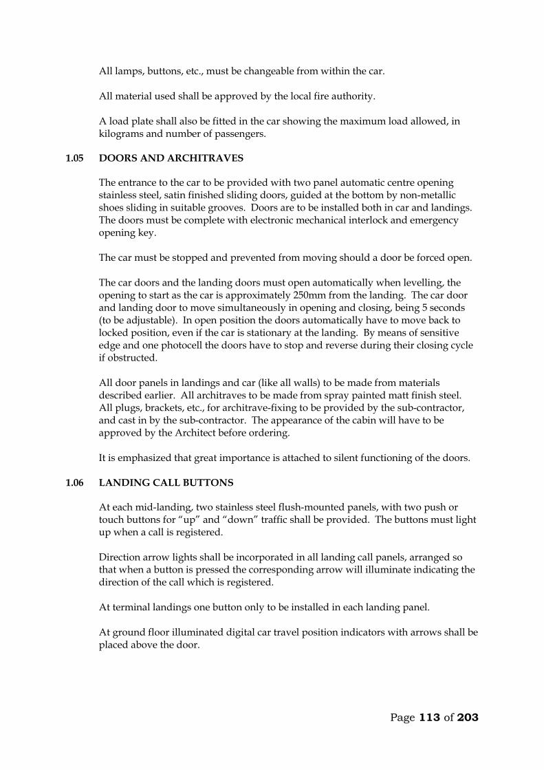
Page 113 of 203
All lamps, buttons, etc., must be changeable from within the car. All material used shall be approved by the local fire authority. A load plate shall also be fitted in the car showing the maximum load allowed, in
kilograms and number of passengers. 1.05 DOORS AND ARCHITRAVES The entrance to the car to be provided with two panel automatic centre opening
stainless steel, satin finished sliding doors, guided at the bottom by non-metallic shoes sliding in suitable grooves. Doors are to be installed both in car and landings. The doors must be complete with electronic mechanical interlock and emergency opening key.
The car must be stopped and prevented from moving should a door be forced open. The car doors and the landing doors must open automatically when levelling, the
opening to start as the car is approximately 250mm from the landing. The car door and landing door to move simultaneously in opening and closing, being 5 seconds (to be adjustable). In open position the doors automatically have to move back to locked position, even if the car is stationary at the landing. By means of sensitive edge and one photocell the doors have to stop and reverse during their closing cycle if obstructed.
All door panels in landings and car (like all walls) to be made from materials
described earlier. All architraves to be made from spray painted matt finish steel. All plugs, brackets, etc., for architrave-fixing to be provided by the sub-contractor, and cast in by the sub-contractor. The appearance of the cabin will have to be approved by the Architect before ordering.
It is emphasized that great importance is attached to silent functioning of the doors.
1.06 LANDING CALL BUTTONS At each mid-landing, two stainless steel flush-mounted panels, with two push or
touch buttons for “up” and “down” traffic shall be provided. The buttons must light up when a call is registered.
Direction arrow lights shall be incorporated in all landing call panels, arranged so
that when a button is pressed the corresponding arrow will illuminate indicating the direction of the call which is registered.
At terminal landings one button only to be installed in each landing panel. At ground floor illuminated digital car travel position indicators with arrows shall be
placed above the door.

Page 114 of 203
1.07 SHAFT INSTALLATIONS Guide rails for car and counterweights to be T-steel guide rails planed on three
edges. Rails must be placed accurately and fixed firmly to the shaft walls with sufficient spacing between brackets. The rails shall be brought totally to the bottom of the shaft.
The fixing of rails and the connection between two or more sections of rail must be in
such a manner that the straight and vertical position is not influenced by changes in temperature or ordinary settlement in the structure.
Guide rails for the car to be either rubber roller guides or Telfon (Tufnol). Roller and
shoes shall be renewable. Buffer must be provided to bring the car counterweight to rest at the extreme limits
of travel, should the car for any reason pass the limit switches. The guide rails, roller shoes, buffers, counter-weight all to be provided and installed
by the Sub-contractor. 1.08 LIFTING MACHINERY
The machine shall be gearless, single wrap traction type, mounted on steel beams fitted on the shaft walls. The beams to be as per structural engineers details. The following information on the machinery must accompany the tender. Make Size, h.p. Voltage, V Power consumption at full load, KW Revolutions per minute, r.p.m. Full load current, A Starting current, A Duration of starting current, sec
Power factor, cos Acceleration time, sec Retardation time, sec The motor must be provided with overload and phase failure cutout devices. The control system to be fitted with a special batter/charger to enable technicians to move cabin to the nearest level to release trapped passengers in case of power failure. The system must prevent engaging of the turning device, until the power supply for the motor is switched off. The aggregate must be dimensioned for the full load in continuous operation and for a temporary overload of 10%. The sub-contractor must provide information on the highest permissible operating temperature for optional functioning of the lift, and about the heat produced by the entire installation.

Page 115 of 203
1.09 ROPES AND SHEAVES The lift shall be provided with durable, flat polyurethane-coated high-tensile steel
belts. Ropes maybe substituted but subject to engineers approval. The sheaves shall be of ample diameter for ropes used. Sheaves shall be fixed by
means of iron beams which are supplied and installed by the sub-contractor. Beams must be sound insulated from structural parts.
1.10 ELECTRICAL INSTALLATION All motors and switchgear shall be rated for operation at 240V/415V, 50 cycles.
Relays and components must be tropicalised. The installation must comply with the IEE Regulations. All wiring shall be carried
out in a neat and orderly manner. Cables run on walls or ceilings to be in straight line and right angle bends enclosed in steel ducting.
Connections to equipment more than 400mm from wall shall be run from the wall in
conduit cast in the floor to a connector box fixed upright adjacent to the equipment and through flexible conduit to the equipment.
All electrical switchgear must be clearly labelled. 1.11 ALARM
An alarm button in the car shall simultaneously activate a bell situated on the car and bell positioned at the security station near the lift lobby at ground floor. The bells shall be supplied with power from a rechargeable dry cell battery supplied by sub-contractor. All wiring and installation of the alarm system shall be done by the sub-contractor.

Page 116 of 203
TECHNICAL DETAILS OF LIFTS OFFERED BY THE TENDERER 9. Lifting Machinery
a) Make b) Size, h.p. c) Power consumption at full load, KW d) Revolutions per minute, r.p.m. e) Full load current, A f) Starting current, A g) Duration of starting current, sec
h) Power factor, cos i) Acceleration time, sec j) Retardation time, sec
10. Delivery Details
Time in weeks from acceptance of tender to delivery of all equipment on site ________ Weeks.
Time in weeks from acceptance of tender to installation and commissioning _________ Weeks. 3. Deviations from the Specification
The Tenderer shall give below details of any Specification, or any deviations, omissions, additions of alternatives in respect of the lifts which he is offering. If none, write None.

Page 117 of 203
MAINTENANCE CONTRACT The Tenderer shall insert in this section the cost of a fully comprehensive Maintenance Contract after one of the initial 12 months maintenance or defects liability period. The sum to be inclusive of regular monthly inspection and breakdown service, and shall include for all tools, parts replacement and service material such as oils, lubricants, etc. ITEM KSHS. Annual Maintenance cost for 1 No. lifts as described
in the following pages inclusive of all spares and 24 hour call services (start date assumed end of building contract). _______________ WARRANTY The warranty period for the equipment and all the associated accessories shall be _______________ months from the date of commissioning. (A minimum of 12 months will be allowed). FOREIGN CURRENCY State the foreign currency applied and the exchange rate to the Kenya Shilling. 1 ____________________ (Foreign Currency) = _____________________ KSh.
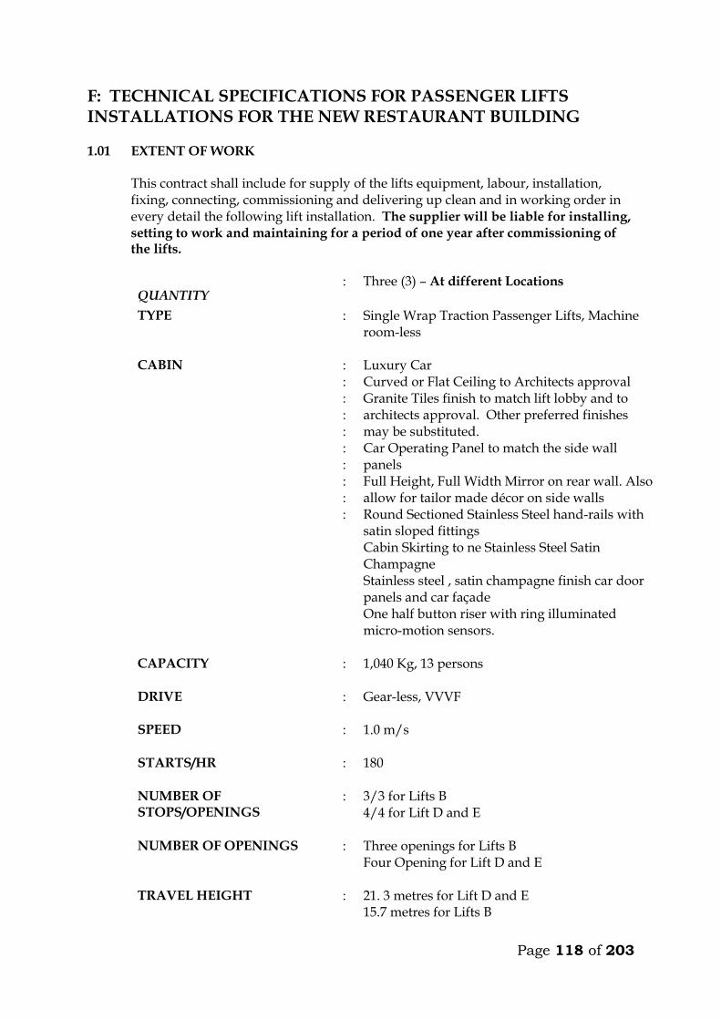
Page 118 of 203
F: TECHNICAL SPECIFICATIONS FOR PASSENGER LIFTS INSTALLATIONS FOR THE NEW RESTAURANT BUILDING 1.01 EXTENT OF WORK This contract shall include for supply of the lifts equipment, labour, installation,
fixing, connecting, commissioning and delivering up clean and in working order in every detail the following lift installation. The supplier will be liable for installing, setting to work and maintaining for a period of one year after commissioning of the lifts.
QUANTITY : Three (3) – At different Locations
TYPE : Single Wrap Traction Passenger Lifts, Machine room-less
CABIN : : : : : : : : : :
Luxury Car Curved or Flat Ceiling to Architects approval Granite Tiles finish to match lift lobby and to architects approval. Other preferred finishes may be substituted. Car Operating Panel to match the side wall panels Full Height, Full Width Mirror on rear wall. Also allow for tailor made décor on side walls Round Sectioned Stainless Steel hand-rails with satin sloped fittings Cabin Skirting to ne Stainless Steel Satin Champagne Stainless steel , satin champagne finish car door panels and car façade One half button riser with ring illuminated micro-motion sensors.
CAPACITY : 1,040 Kg, 13 persons
DRIVE : Gear-less, VVVF
SPEED : 1.0 m/s
STARTS/HR : 180
NUMBER OF STOPS/OPENINGS
: 3/3 for Lifts B 4/4 for Lift D and E
NUMBER OF OPENINGS : Three openings for Lifts B Four Opening for Lift D and E
TRAVEL HEIGHT : 21. 3 metres for Lift D and E 15.7 metres for Lifts B
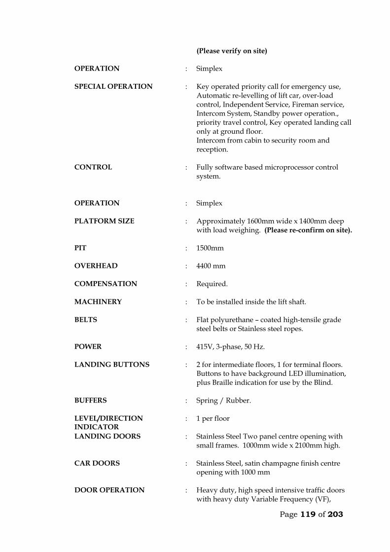
Page 119 of 203
(Please verify on site)
OPERATION : Simplex
SPECIAL OPERATION : Key operated priority call for emergency use, Automatic re-levelling of lift car, over-load control, Independent Service, Fireman service, Intercom System, Standby power operation., priority travel control, Key operated landing call only at ground floor. Intercom from cabin to security room and reception.
CONTROL : Fully software based microprocessor control system.
OPERATION : Simplex
PLATFORM SIZE : Approximately 1600mm wide x 1400mm deep
with load weighing. (Please re-confirm on site).
PIT : 1500mm
OVERHEAD : 4400 mm
COMPENSATION : Required.
MACHINERY : To be installed inside the lift shaft.
BELTS : Flat polyurethane – coated high-tensile grade steel belts or Stainless steel ropes.
POWER : 415V, 3-phase, 50 Hz.
LANDING BUTTONS : 2 for intermediate floors, 1 for terminal floors. Buttons to have background LED illumination, plus Braille indication for use by the Blind.
BUFFERS : Spring / Rubber.
LEVEL/DIRECTION INDICATOR
: 1 per floor
LANDING DOORS : Stainless Steel Two panel centre opening with small frames. 1000mm wide x 2100mm high.
CAR DOORS : Stainless Steel, satin champagne finish centre opening with 1000 mm
DOOR OPERATION : Heavy duty, high speed intensive traffic doors with heavy duty Variable Frequency (VF),
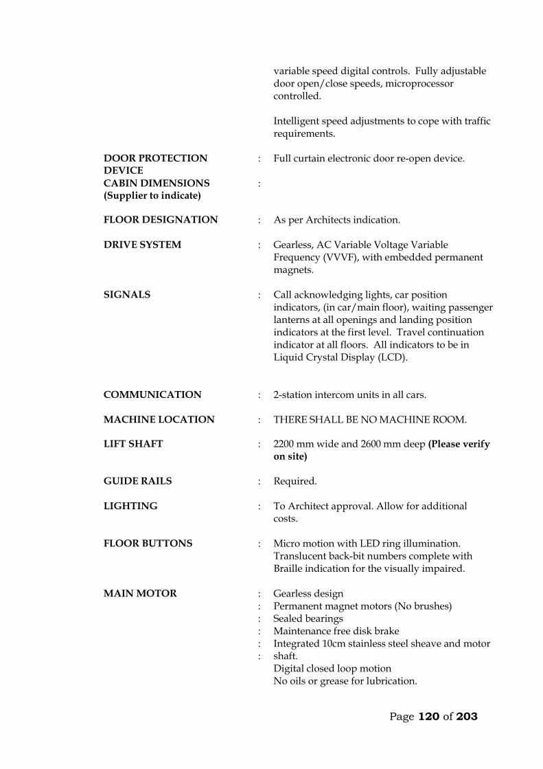
Page 120 of 203
variable speed digital controls. Fully adjustable door open/close speeds, microprocessor controlled. Intelligent speed adjustments to cope with traffic requirements.
DOOR PROTECTION DEVICE
: Full curtain electronic door re-open device.
CABIN DIMENSIONS (Supplier to indicate)
:
FLOOR DESIGNATION : As per Architects indication.
DRIVE SYSTEM : Gearless, AC Variable Voltage Variable Frequency (VVVF), with embedded permanent magnets.
SIGNALS : Call acknowledging lights, car position indicators, (in car/main floor), waiting passenger lanterns at all openings and landing position indicators at the first level. Travel continuation indicator at all floors. All indicators to be in Liquid Crystal Display (LCD).
COMMUNICATION : 2-station intercom units in all cars.
MACHINE LOCATION
: THERE SHALL BE NO MACHINE ROOM.
LIFT SHAFT : 2200 mm wide and 2600 mm deep (Please verify on site)
GUIDE RAILS : Required.
LIGHTING : To Architect approval. Allow for additional costs.
FLOOR BUTTONS : Micro motion with LED ring illumination. Translucent back-bit numbers complete with Braille indication for the visually impaired.
MAIN MOTOR : : : : : :
Gearless design Permanent magnet motors (No brushes) Sealed bearings Maintenance free disk brake Integrated 10cm stainless steel sheave and motor shaft. Digital closed loop motion No oils or grease for lubrication.
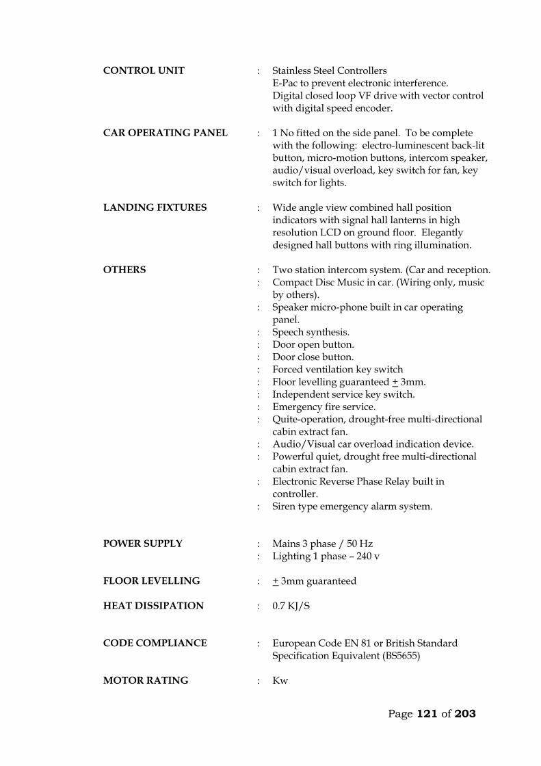
Page 121 of 203
CONTROL UNIT : Stainless Steel Controllers E-Pac to prevent electronic interference. Digital closed loop VF drive with vector control with digital speed encoder.
CAR OPERATING PANEL : 1 No fitted on the side panel. To be complete with the following: electro-luminescent back-lit button, micro-motion buttons, intercom speaker, audio/visual overload, key switch for fan, key switch for lights.
LANDING FIXTURES : Wide angle view combined hall position indicators with signal hall lanterns in high resolution LCD on ground floor. Elegantly designed hall buttons with ring illumination.
OTHERS : Two station intercom system. (Car and reception. : Compact Disc Music in car. (Wiring only, music
by others). : Speaker micro-phone built in car operating
panel. : Speech synthesis. : Door open button. : Door close button. : Forced ventilation key switch : Floor levelling guaranteed + 3mm. : Independent service key switch. : Emergency fire service. : Quite-operation, drought-free multi-directional
cabin extract fan. : Audio/Visual car overload indication device. : Powerful quiet, drought free multi-directional
cabin extract fan. : Electronic Reverse Phase Relay built in
controller. : Siren type emergency alarm system.
POWER SUPPLY : :
Mains 3 phase / 50 Hz Lighting 1 phase – 240 v
FLOOR LEVELLING : + 3mm guaranteed
HEAT DISSIPATION : 0.7 KJ/S
CODE COMPLIANCE : European Code EN 81 or British Standard Specification Equivalent (BS5655)
MOTOR RATING : Kw
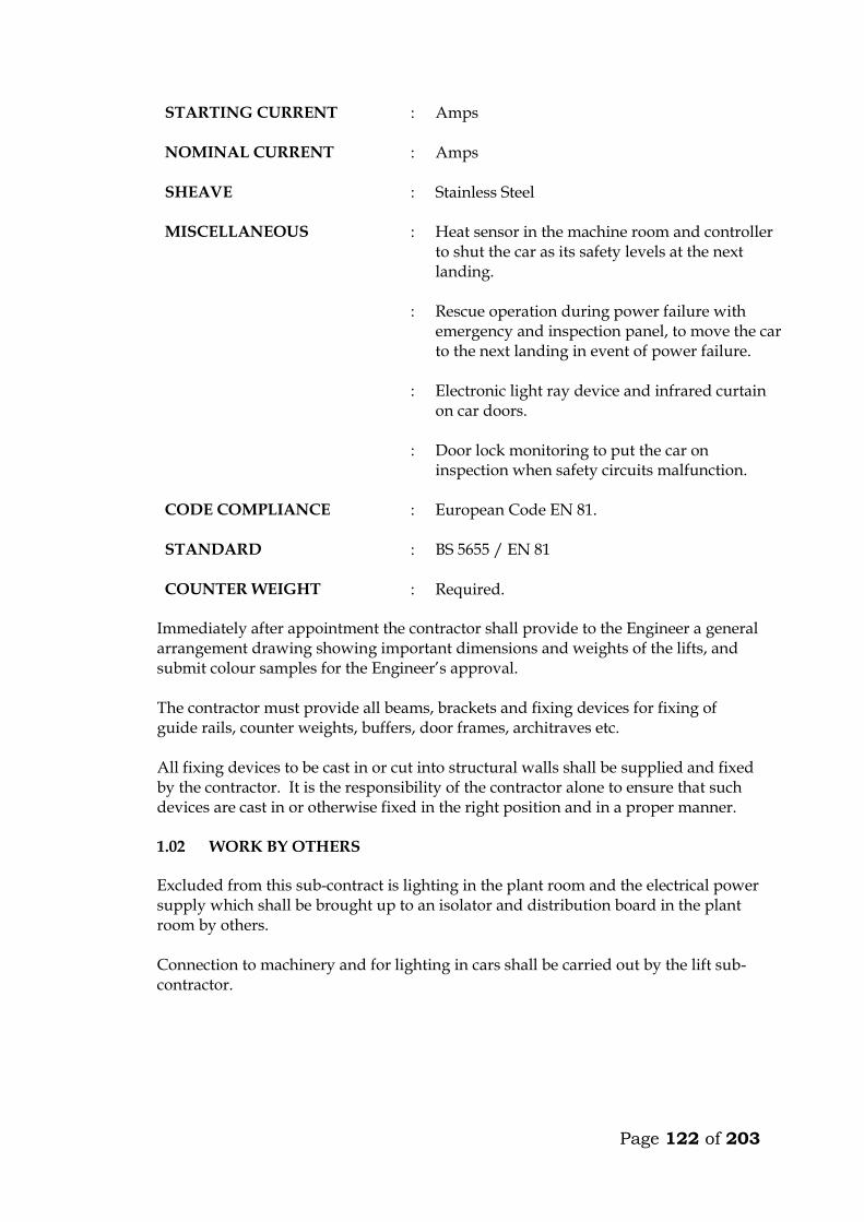
Page 122 of 203
STARTING CURRENT : Amps
NOMINAL CURRENT : Amps
SHEAVE : Stainless Steel
MISCELLANEOUS : Heat sensor in the machine room and controller to shut the car as its safety levels at the next landing.
: Rescue operation during power failure with emergency and inspection panel, to move the car to the next landing in event of power failure.
: Electronic light ray device and infrared curtain on car doors.
: Door lock monitoring to put the car on inspection when safety circuits malfunction.
CODE COMPLIANCE : European Code EN 81.
STANDARD : BS 5655 / EN 81
COUNTER WEIGHT : Required. Immediately after appointment the contractor shall provide to the Engineer a general
arrangement drawing showing important dimensions and weights of the lifts, and submit colour samples for the Engineer’s approval.
The contractor must provide all beams, brackets and fixing devices for fixing of
guide rails, counter weights, buffers, door frames, architraves etc. All fixing devices to be cast in or cut into structural walls shall be supplied and fixed
by the contractor. It is the responsibility of the contractor alone to ensure that such devices are cast in or otherwise fixed in the right position and in a proper manner.
1.02 WORK BY OTHERS
Excluded from this sub-contract is lighting in the plant room and the electrical power supply which shall be brought up to an isolator and distribution board in the plant room by others. Connection to machinery and for lighting in cars shall be carried out by the lift sub-contractor.

Page 123 of 203
1.03 OPERATION
The car shall travel at a maximum speed of 1.0m/s in all floors. The car must not start unless the car doors are in a closed position and all landing doors are locked in a closed position. Should the load on the car exceed the maximum load, the car and landing doors are to be prevented from closing. Car levelling shall be within 12mm by means of an automatic self-levelling device. An emergency stop button in the car shall stop the car completely even after the button is released. Re-starting shall take place only by activation of a push button in the car and not by a call from any landing. Terminal limit switches must stop the car automatically at the terminal landings. Final limit switches must cut off power and apply the brake automatically, should the car pass the terminal landings. The installation must be provided with a complete controller device to control starting, stopping and speed as well as emergency stopping of the car in case any of the safety devices do not operate or excessive descending or ascending speed is attained by cutting off power to the motor and activation of the brake. Calls in the car must be given preference over calls from landings. At ground floor, calls shall be by means of a key operated switch only for authorised people. The car must deal with calls in sequence and not be intercepted during their trips by additional calls from car or landings. The lift must be provided with automatic bypass devices to prevent unnecessary stops when the car is full. The car must not stop during the “up” trip at any landing in response to a “down” landing call, unless this call is the highest one registered. For inspection purpose a manually operated switch on the controller connected to “up” and “down” direction buttons exposed on the top of the car, must be provided. This switch must permit the car to be operated at slow speed from the top of the car. During this inspection the car must not respond to any calls.
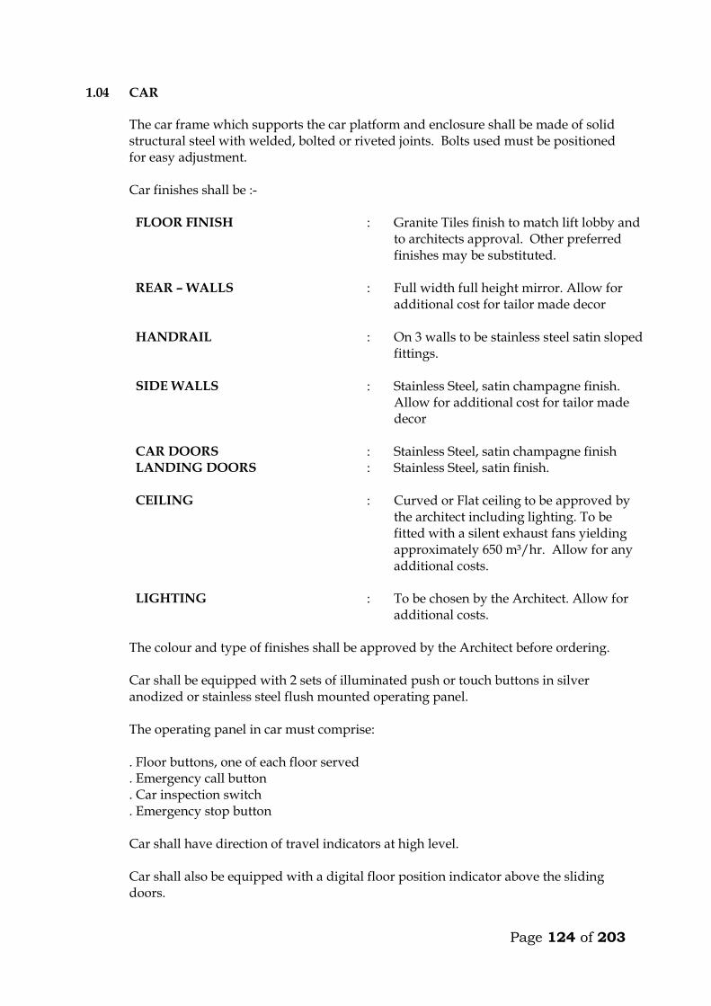
Page 124 of 203
1.04 CAR The car frame which supports the car platform and enclosure shall be made of solid
structural steel with welded, bolted or riveted joints. Bolts used must be positioned for easy adjustment. Car finishes shall be :-
FLOOR FINISH : Granite Tiles finish to match lift lobby and
to architects approval. Other preferred finishes may be substituted.
REAR – WALLS : Full width full height mirror. Allow for additional cost for tailor made decor
HANDRAIL : On 3 walls to be stainless steel satin sloped fittings.
SIDE WALLS : Stainless Steel, satin champagne finish. Allow for additional cost for tailor made decor
CAR DOORS : Stainless Steel, satin champagne finish LANDING DOORS : Stainless Steel, satin finish.
CEILING : Curved or Flat ceiling to be approved by
the architect including lighting. To be fitted with a silent exhaust fans yielding approximately 650 m³/hr. Allow for any additional costs.
LIGHTING : To be chosen by the Architect. Allow for additional costs.
The colour and type of finishes shall be approved by the Architect before ordering. Car shall be equipped with 2 sets of illuminated push or touch buttons in silver
anodized or stainless steel flush mounted operating panel. The operating panel in car must comprise: . Floor buttons, one of each floor served . Emergency call button . Car inspection switch . Emergency stop button Car shall have direction of travel indicators at high level. Car shall also be equipped with a digital floor position indicator above the sliding
doors.

Page 125 of 203
All lamps, buttons, etc., must be changeable from within the car. All material used shall be approved by the local fire authority. A load plate shall also be fitted in the car showing the maximum load allowed, in
kilograms and number of passengers. 1.05 DOORS AND ARCHITRAVES The entrance to the car to be provided with two panel automatic centre opening
stainless steel, satin finished sliding doors, guided at the bottom by non-metallic shoes sliding in suitable grooves. Doors are to be installed both in car and landings. The doors must be complete with electronic mechanical interlock and emergency opening key.
The car must be stopped and prevented from moving should a door be forced open. The car doors and the landing doors must open automatically when levelling, the
opening to start as the car is approximately 250mm from the landing. The car door and landing door to move simultaneously in opening and closing, being 5 seconds (to be adjustable). In open position the doors automatically have to move back to locked position, even if the car is stationary at the landing. By means of sensitive edge and one photocell the doors have to stop and reverse during their closing cycle if obstructed.
All door panels in landings and car (like all walls) to be made from materials
described earlier. All architraves to be made from spray painted matt finish steel. All plugs, brackets, etc., for architrave-fixing to be provided by the sub-contractor, and cast in by the sub-contractor. The appearance of the cabin will have to be approved by the Architect before ordering.
It is emphasized that great importance is attached to silent functioning of the doors.
1.06 LANDING CALL BUTTONS At each mid-landing, two stainless steel flush-mounted panels, with two push or
touch buttons for “up” and “down” traffic shall be provided. The buttons must light up when a call is registered.
Direction arrow lights shall be incorporated in all landing call panels, arranged so
that when a button is pressed the corresponding arrow will illuminate indicating the direction of the call which is registered.
At terminal landings one button only to be installed in each landing panel. At ground floor illuminated digital car travel position indicators with arrows shall be
placed above the door.

Page 126 of 203
1.07 SHAFT INSTALLATIONS Guide rails for car and counterweights to be T-steel guide rails planed on three
edges. Rails must be placed accurately and fixed firmly to the shaft walls with sufficient spacing between brackets. The rails shall be brought totally to the bottom of the shaft.
The fixing of rails and the connection between two or more sections of rail must be in
such a manner that the straight and vertical position is not influenced by changes in temperature or ordinary settlement in the structure.
Guide rails for the car to be either rubber roller guides or Telfon (Tufnol). Roller and
shoes shall be renewable. Buffer must be provided to bring the car counterweight to rest at the extreme limits
of travel, should the car for any reason pass the limit switches. The guide rails, roller shoes, buffers, counter-weight all to be provided and installed
by the Sub-contractor. 1.08 LIFTING MACHINERY
The machine shall be gearless, single wrap traction type, mounted on steel beams fitted on the shaft walls. The beams to be as per structural engineers details. The following information on the machinery must accompany the tender. Make Size, h.p. Voltage, V Power consumption at full load, KW Revolutions per minute, r.p.m. Full load current, A Starting current, A Duration of starting current, sec
Power factor, cos Acceleration time, sec Retardation time, sec The motor must be provided with overload and phase failure cutout devices. The control system to be fitted with a special batter/charger to enable technicians to move cabin to the nearest level to release trapped passengers in case of power failure. The system must prevent engaging of the turning device, until the power supply for the motor is switched off. The aggregate must be dimensioned for the full load in continuous operation and for a temporary overload of 10%. The sub-contractor must provide information on the highest permissible operating temperature for optional functioning of the lift, and about the heat produced by the entire installation.

Page 127 of 203
1.09 ROPES AND SHEAVES The lift shall be provided with durable, flat polyurethane-coated high-tensile steel
belts. Ropes maybe substituted but subject to engineers approval. The sheaves shall be of ample diameter for ropes used. Sheaves shall be fixed by
means of iron beams which are supplied and installed by the sub-contractor. Beams must be sound insulated from structural parts.
1.10 ELECTRICAL INSTALLATION All motors and switchgear shall be rated for operation at 240V/415V, 50 cycles.
Relays and components must be tropicalised. The installation must comply with the IEE Regulations. All wiring shall be carried
out in a neat and orderly manner. Cables run on walls or ceilings to be in straight line and right angle bends enclosed in steel ducting.
Connections to equipment more than 400mm from wall shall be run from the wall in
conduit cast in the floor to a connector box fixed upright adjacent to the equipment and through flexible conduit to the equipment.
All electrical switchgear must be clearly labelled. 1.11 ALARM
An alarm button in the car shall simultaneously activate a bell situated on the car and bell positioned at the security station near the lift lobby at ground floor. The bells shall be supplied with power from a rechargeable dry cell battery supplied by sub-contractor. All wiring and installation of the alarm system shall be done by the sub-contractor.

Page 128 of 203
TECHNICAL DETAILS OF LIFTS OFFERED BY THE TENDERER 11. Lifting Machinery
a) Make b) Size, h.p. c) Power consumption at full load, KW d) Revolutions per minute, r.p.m. e) Full load current, A f) Starting current, A g) Duration of starting current, sec
h) Power factor, cos i) Acceleration time, sec j) Retardation time, sec
12. Delivery Details
Time in weeks from acceptance of tender to delivery of all equipment on site ________ Weeks.
Time in weeks from acceptance of tender to installation and commissioning _________ Weeks. 3. Deviations from the Specification
The Tenderer shall give below details of any Specification, or any deviations, omissions, additions of alternatives in respect of the lifts which he is offering. If none, write None.

Page 129 of 203
MAINTENANCE CONTRACT The Tenderer shall insert in this section the cost of a fully comprehensive Maintenance Contract after one of the initial 12 months maintenance or defects liability period. The sum to be inclusive of regular monthly inspection and breakdown service, and shall include for all tools, parts replacement and service material such as oils, lubricants, etc. ITEM KSHS. Annual Maintenance cost for 1 No. lifts as described
in the following pages inclusive of all spares and 24 hour call services (start date assumed end of building contract). _______________ WARRANTY The warranty period for the equipment and all the associated accessories shall be _______________ months from the date of commissioning. (A minimum of 12 months will be allowed). FOREIGN CURRENCY State the foreign currency applied and the exchange rate to the Kenya Shilling. 1 ____________________ (Foreign Currency) = _____________________ KSh.
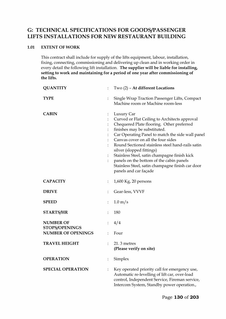
Page 130 of 203
G: TECHNICAL SPECIFICATIONS FOR GOODS/PASSENGER LIFTS INSTALLATIONS FOR NEW RESTAURANT BUILDING 1.01 EXTENT OF WORK This contract shall include for supply of the lifts equipment, labour, installation,
fixing, connecting, commissioning and delivering up clean and in working order in every detail the following lift installation. The supplier will be liable for installing, setting to work and maintaining for a period of one year after commissioning of the lifts.
QUANTITY : Two (2) – At different Locations
TYPE : Single Wrap Traction Passenger Lifts, Compact
Machine room or Machine room-less
CABIN : : : : : : : : :
Luxury Car Curved or Flat Ceiling to Architects approval Chequered Plate flooring. Other preferred finishes may be substituted. Car Operating Panel to match the side wall panel Canvas cover on all the four sides Round Sectioned stainless steel hand-rails satin silver (slopped fittings) Stainless Steel, satin champagne finish kick panels on the bottom of the cabin panels Stainless Steel, satin champagne finish car door panels and car façade
CAPACITY : 1,600 Kg, 20 persons
DRIVE : Gear-less, VVVF
SPEED : 1.0 m/s
STARTS/HR : 180
NUMBER OF STOPS/OPENINGS
: 4/4
NUMBER OF OPENINGS : Four
TRAVEL HEIGHT : 21. 3 metres (Please verify on site)
OPERATION : Simplex
SPECIAL OPERATION : Key operated priority call for emergency use, Automatic re-levelling of lift car, over-load control, Independent Service, Fireman service, Intercom System, Standby power operation.,
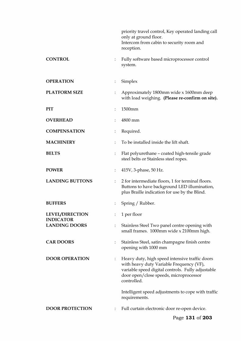
Page 131 of 203
priority travel control, Key operated landing call only at ground floor. Intercom from cabin to security room and reception.
CONTROL : Fully software based microprocessor control system.
OPERATION : Simplex
PLATFORM SIZE : Approximately 1800mm wide x 1600mm deep
with load weighing. (Please re-confirm on site).
PIT : 1500mm
OVERHEAD : 4800 mm
COMPENSATION : Required.
MACHINERY : To be installed inside the lift shaft.
BELTS : Flat polyurethane – coated high-tensile grade steel belts or Stainless steel ropes.
POWER : 415V, 3-phase, 50 Hz.
LANDING BUTTONS : 2 for intermediate floors, 1 for terminal floors. Buttons to have background LED illumination, plus Braille indication for use by the Blind.
BUFFERS : Spring / Rubber.
LEVEL/DIRECTION INDICATOR
: 1 per floor
LANDING DOORS : Stainless Steel Two panel centre opening with small frames. 1000mm wide x 2100mm high.
CAR DOORS : Stainless Steel, satin champagne finish centre opening with 1000 mm
DOOR OPERATION : Heavy duty, high speed intensive traffic doors with heavy duty Variable Frequency (VF), variable speed digital controls. Fully adjustable door open/close speeds, microprocessor controlled. Intelligent speed adjustments to cope with traffic requirements.
DOOR PROTECTION : Full curtain electronic door re-open device.
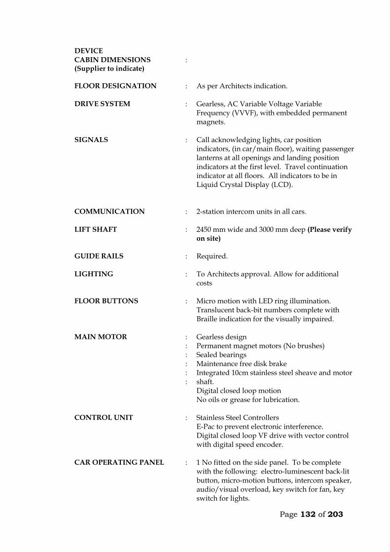
Page 132 of 203
DEVICE CABIN DIMENSIONS (Supplier to indicate)
:
FLOOR DESIGNATION : As per Architects indication.
DRIVE SYSTEM : Gearless, AC Variable Voltage Variable Frequency (VVVF), with embedded permanent magnets.
SIGNALS : Call acknowledging lights, car position indicators, (in car/main floor), waiting passenger lanterns at all openings and landing position indicators at the first level. Travel continuation indicator at all floors. All indicators to be in Liquid Crystal Display (LCD).
COMMUNICATION : 2-station intercom units in all cars.
LIFT SHAFT : 2450 mm wide and 3000 mm deep (Please verify
on site)
GUIDE RAILS : Required.
LIGHTING : To Architects approval. Allow for additional costs
FLOOR BUTTONS : Micro motion with LED ring illumination. Translucent back-bit numbers complete with Braille indication for the visually impaired.
MAIN MOTOR : : : : : :
Gearless design Permanent magnet motors (No brushes) Sealed bearings Maintenance free disk brake Integrated 10cm stainless steel sheave and motor shaft. Digital closed loop motion No oils or grease for lubrication.
CONTROL UNIT : Stainless Steel Controllers E-Pac to prevent electronic interference. Digital closed loop VF drive with vector control with digital speed encoder.
CAR OPERATING PANEL : 1 No fitted on the side panel. To be complete with the following: electro-luminescent back-lit button, micro-motion buttons, intercom speaker, audio/visual overload, key switch for fan, key switch for lights.
Page 133 of 203
LANDING FIXTURES : Wide angle view combined hall position
indicators with signal hall lanterns in high resolution LCD on ground floor. Elegantly designed hall buttons with ring illumination.
OTHERS : Two station intercom system. (Car and reception. : Compact Disc Music in car. (Wiring only, music
by others). : Speaker micro-phone built in car operating
panel. : Speech synthesis. : Door open button. : Door close button. : Forced ventilation key switch : Floor levelling guaranteed + 3mm. : Independent service key switch. : Emergency fire service. : Quite-operation, drought-free multi-directional
cabin extract fan. : Audio/Visual car overload indication device. : Powerful quiet, drought free multi-directional
cabin extract fan. : Electronic Reverse Phase Relay built in
controller. : Siren type emergency alarm system.
POWER SUPPLY : :
Mains 3 phase / 50 Hz Lighting 1 phase – 240 v
FLOOR LEVELLING : + 3mm guaranteed
HEAT DISSIPATION : 0.7 KJ/S
CODE COMPLIANCE : European Code EN 81 or British Standard Specification Equivalent (BS5655)
MOTOR RATING : Kw
STARTING CURRENT : Amps
NOMINAL CURRENT : Amps
SHEAVE : Stainless Steel
MISCELLANEOUS : Heat sensor in the machine room and controller to shut the car as its safety levels at the next landing.
Page 134 of 203
: Rescue operation during power failure with emergency and inspection panel, to move the car to the next landing in event of power failure.
: Electronic light ray device and infrared curtain on car doors.
: Door lock monitoring to put the car on inspection when safety circuits malfunction.
CODE COMPLIANCE : European Code EN 81.
STANDARD : BS 5655 / EN 81
COUNTER WEIGHT : Required. Immediately after appointment the contractor shall provide to the Engineer a general
arrangement drawing showing important dimensions and weights of the lifts, and submit colour samples for the Engineer’s approval.
The contractor must provide all beams, brackets and fixing devices for fixing of
guide rails, counter weights, buffers, door frames, architraves etc. All fixing devices to be cast in or cut into structural walls shall be supplied and fixed
by the contractor. It is the responsibility of the contractor alone to ensure that such devices are cast in or otherwise fixed in the right position and in a proper manner.
1.02 WORK BY OTHERS
Excluded from this sub-contract is lighting in the plant room and the electrical power supply which shall be brought up to an isolator and distribution board in the plant room by others. Connection to machinery and for lighting in cars shall be carried out by the lift sub-contractor.
1.03 OPERATION
The car shall travel at a maximum speed of 1.0m/s in all floors. The car must not start unless the car doors are in a closed position and all landing doors are locked in a closed position. Should the load on the car exceed the maximum load, the car and landing doors are to be prevented from closing. Car levelling shall be within 12mm by means of an automatic self-levelling device. An emergency stop button in the car shall stop the car completely even after the button is released. Re-starting shall take place only by activation of a push button in the car and not by a call from any landing. Terminal limit switches must stop the car automatically at the terminal landings.
Page 135 of 203
Final limit switches must cut off power and apply the brake automatically, should the car pass the terminal landings. The installation must be provided with a complete controller device to control starting, stopping and speed as well as emergency stopping of the car in case any of the safety devices do not operate or excessive descending or ascending speed is attained by cutting off power to the motor and activation of the brake. Calls in the car must be given preference over calls from landings. At ground floor, calls shall be by means of a key operated switch only for authorised people. The car must deal with calls in sequence and not be intercepted during their trips by additional calls from car or landings. The lift must be provided with automatic bypass devices to prevent unnecessary stops when the car is full. The car must not stop during the “up” trip at any landing in response to a “down” landing call, unless this call is the highest one registered. For inspection purpose a manually operated switch on the controller connected to “up” and “down” direction buttons exposed on the top of the car, must be provided. This switch must permit the car to be operated at slow speed from the top of the car. During this inspection the car must not respond to any calls.
1.04 CAR The car frame which supports the car platform and enclosure shall be made of solid
structural steel with welded, bolted or riveted joints. Bolts used must be positioned for easy adjustment. Car finishes shall be :-
FLOOR FINISH : Chequered Plate flooring. Other preferred finishes may be substituted.
REAR – WALLS : Stainless Steel, satin champagne finish with removable Canvas covering.
HANDRAIL : On 3 walls to be satin silver finished stainless steel rail with sloped fittings.
SIDE WALLS : Stainless Steel, satin champagne finish with removable Canvas Covering
CAR DOORS : Stainless Steel, satin champagne finish.
Page 136 of 203
LANDING DOORS : Stainless Steel, satin finish.
CEILING : To Architects approval. Allow for any additional costs. Also to be fitted with silent exhausts fan yielding approximately 650 m³/hr.
LIGHTING : To Architects approval. Allow for any additional costs.
The colour and type of finishes shall be approved by the Architect before ordering. Car shall be equipped with 2 sets of illuminated push or touch buttons in silver
anodized or stainless steel flush mounted operating panel. The operating panel in car must comprise: . Floor buttons, one of each floor served . Emergency call button . Car inspection switch . Emergency stop button Car shall have direction of travel indicators at high level. Car shall also be equipped with a digital floor position indicator above the sliding
doors. All lamps, buttons, etc., must be changeable from within the car. All material used shall be approved by the local fire authority. A load plate shall also be fitted in the car showing the maximum load allowed, in
kilograms and number of passengers. 1.05 DOORS AND ARCHITRAVES The entrance to the car to be provided with two panel automatic centre opening
stainless steel, satin finished sliding doors, guided at the bottom by non-metallic shoes sliding in suitable grooves. Doors are to be installed both in car and landings. The doors must be complete with electronic mechanical interlock and emergency opening key.
The car must be stopped and prevented from moving should a door be forced open. The car doors and the landing doors must open automatically when levelling, the
opening to start as the car is approximately 250mm from the landing. The car door and landing door to move simultaneously in opening and closing, being 5 seconds (to be adjustable). In open position the doors automatically have to move back to locked position, even if the car is stationary at the landing. By means of sensitive
Page 137 of 203
edge and one photocell the doors have to stop and reverse during their closing cycle if obstructed.
All door panels in landings and car (like all walls) to be made from materials
described earlier. All architraves to be made from spray painted matt finish steel. All plugs, brackets, etc., for architrave-fixing to be provided by the sub-contractor, and cast in by the sub-contractor. The appearance of the cabin will have to be approved by the Architect before ordering.
It is emphasized that great importance is attached to silent functioning of the doors.
1.06 LANDING CALL BUTTONS At each mid-landing, two stainless steel flush-mounted panels, with two push or
touch buttons for “up” and “down” traffic shall be provided. The buttons must light up when a call is registered.
Direction arrow lights shall be incorporated in all landing call panels, arranged so
that when a button is pressed the corresponding arrow will illuminate indicating the direction of the call which is registered.
At terminal landings one button only to be installed in each landing panel. At ground floor illuminated digital car travel position indicators with arrows shall be
placed above the door. 1.07 SHAFT INSTALLATIONS Guide rails for car and counterweights to be T-steel guide rails planed on three
edges. Rails must be placed accurately and fixed firmly to the shaft walls with sufficient spacing between brackets. The rails shall be brought totally to the bottom of the shaft.
The fixing of rails and the connection between two or more sections of rail must be in
such a manner that the straight and vertical position is not influenced by changes in temperature or ordinary settlement in the structure.
Guide rails for the car to be either rubber roller guides or Telfon (Tufnol). Roller and
shoes shall be renewable. Buffer must be provided to bring the car counterweight to rest at the extreme limits
of travel, should the car for any reason pass the limit switches. The guide rails, roller shoes, buffers, counter-weight all to be provided and installed
by the Sub-contractor.
Page 138 of 203
1.08 LIFTING MACHINERY
The machine shall be gearless, single wrap traction type, mounted on steel beams fitted on the shaft walls. The beams to be as per structural engineers details. The following information on the machinery must accompany the tender. Make Size, h.p. Voltage, V Power consumption at full load, KW Revolutions per minute, r.p.m. Full load current, A Starting current, A Duration of starting current, sec
Power factor, cos Acceleration time, sec Retardation time, sec The motor must be provided with overload and phase failure cutout devices. The control system to be fitted with a special batter/charger to enable technicians to move cabin to the nearest level to release trapped passengers in case of power failure. The system must prevent engaging of the turning device, until the power supply for the motor is switched off. The aggregate must be dimensioned for the full load in continuous operation and for a temporary overload of 10%. The sub-contractor must provide information on the highest permissible operating temperature for optional functioning of the lift, and about the heat produced by the entire installation.
1.09 ROPES AND SHEAVES The lift shall be provided with durable, flat polyurethane-coated high-tensile steel
belts. Ropes maybe substituted but subject to engineers approval. The sheaves shall be of ample diameter for ropes used. Sheaves shall be fixed by
means of iron beams which are supplied and installed by the sub-contractor. Beams must be sound insulated from structural parts.
1.10 ELECTRICAL INSTALLATION All motors and switchgear shall be rated for operation at 240V/415V, 50 cycles.
Relays and components must be tropicalised. The installation must comply with the IEE Regulations. All wiring shall be carried
out in a neat and orderly manner. Cables run on walls or ceilings to be in straight line and right angle bends enclosed in steel ducting.
Page 139 of 203
Connections to equipment more than 400mm from wall shall be run from the wall in conduit cast in the floor to a connector box fixed upright adjacent to the equipment and through flexible conduit to the equipment.
All electrical switchgear must be clearly labelled. 1.11 ALARM
An alarm button in the car shall simultaneously activate a bell situated on the car and bell positioned at the security station near the lift lobby at ground floor. The bells shall be supplied with power from a rechargeable dry cell battery supplied by sub-contractor. All wiring and installation of the alarm system shall be done by the sub-contractor.

Page 140 of 203
TECHNICAL DETAILS OF LIFTS OFFERED BY THE TENDERER 13. Lifting Machinery
a) Make b) Size, h.p. c) Power consumption at full load, KW d) Revolutions per minute, r.p.m. e) Full load current, A f) Starting current, A g) Duration of starting current, sec
h) Power factor, cos i) Acceleration time, sec j) Retardation time, sec
14. Delivery Details
Time in weeks from acceptance of tender to delivery of all equipment on site ________ Weeks.
Time in weeks from acceptance of tender to installation and commissioning _________ Weeks. 3. Deviations from the Specification
The Tenderer shall give below details of any Specification, or any deviations, omissions, additions of alternatives in respect of the lifts which he is offering. If none, write None.
Page 141 of 203
MAINTENANCE CONTRACT The Tenderer shall insert in this section the cost of a fully comprehensive Maintenance Contract after one of the initial 12 months maintenance or defects liability period. The sum to be inclusive of regular monthly inspection and breakdown service, and shall include for all tools, parts replacement and service material such as oils, lubricants, etc. ITEM KSHS. Annual Maintenance cost for 1 No. lifts as described
in the following pages inclusive of all spares and 24 hour call services (start date assumed end of building contract). _______________ WARRANTY The warranty period for the equipment and all the associated accessories shall be _______________ months from the date of commissioning. (A minimum of 12 months will be allowed). FOREIGN CURRENCY State the foreign currency applied and the exchange rate to the Kenya Shilling. 1 ____________________ (Foreign Currency) = _____________________ KSh.
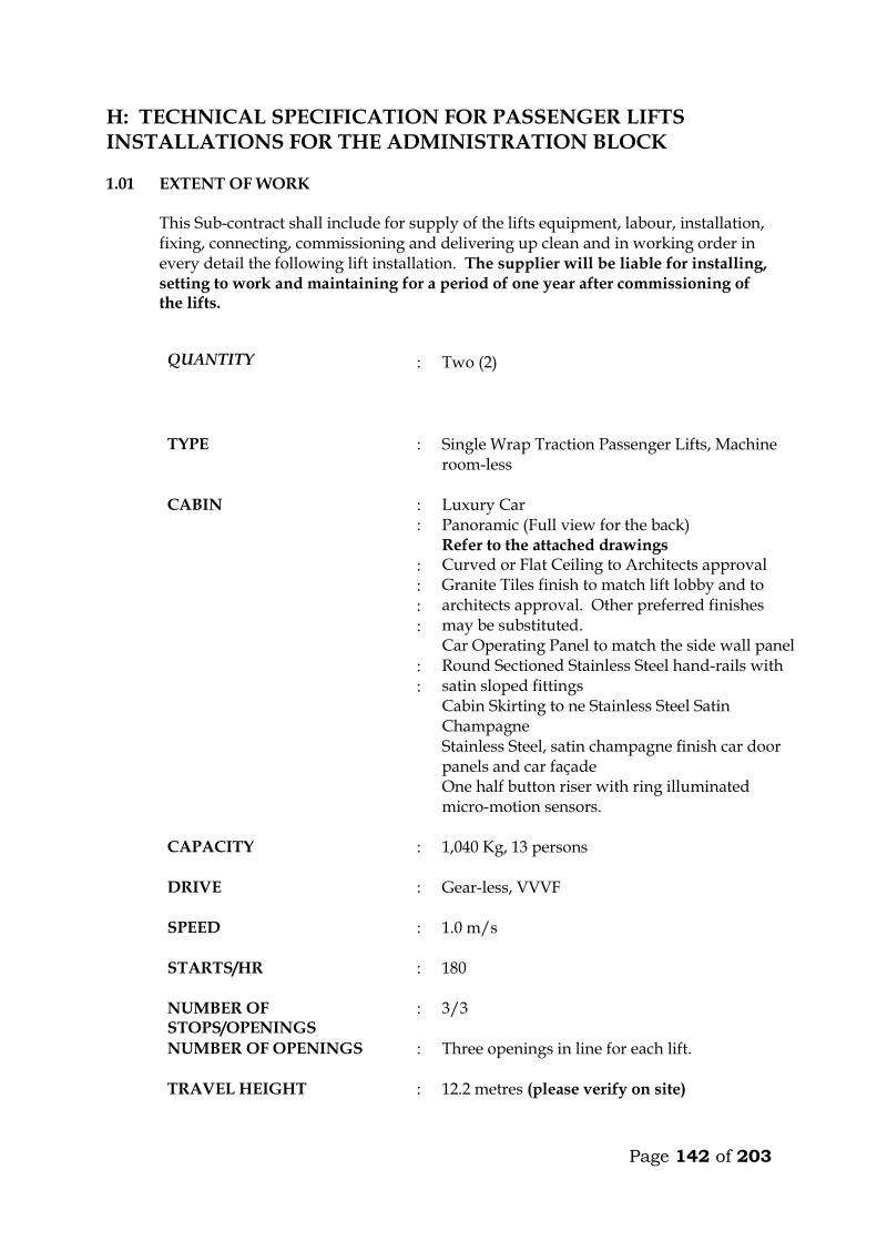
Page 142 of 203
H: TECHNICAL SPECIFICATION FOR PASSENGER LIFTS INSTALLATIONS FOR THE ADMINISTRATION BLOCK 1.01 EXTENT OF WORK This Sub-contract shall include for supply of the lifts equipment, labour, installation,
fixing, connecting, commissioning and delivering up clean and in working order in every detail the following lift installation. The supplier will be liable for installing, setting to work and maintaining for a period of one year after commissioning of the lifts.
QUANTITY :
Two (2)
TYPE : Single Wrap Traction Passenger Lifts, Machine room-less
CABIN
: : : : : : : :
Luxury Car Panoramic (Full view for the back) Refer to the attached drawings Curved or Flat Ceiling to Architects approval Granite Tiles finish to match lift lobby and to architects approval. Other preferred finishes may be substituted. Car Operating Panel to match the side wall panel Round Sectioned Stainless Steel hand-rails with satin sloped fittings Cabin Skirting to ne Stainless Steel Satin Champagne Stainless Steel, satin champagne finish car door panels and car façade One half button riser with ring illuminated micro-motion sensors.
CAPACITY : 1,040 Kg, 13 persons
DRIVE : Gear-less, VVVF
SPEED : 1.0 m/s
STARTS/HR : 180
NUMBER OF STOPS/OPENINGS
: 3/3
NUMBER OF OPENINGS : Three openings in line for each lift.
TRAVEL HEIGHT : 12.2 metres (please verify on site)
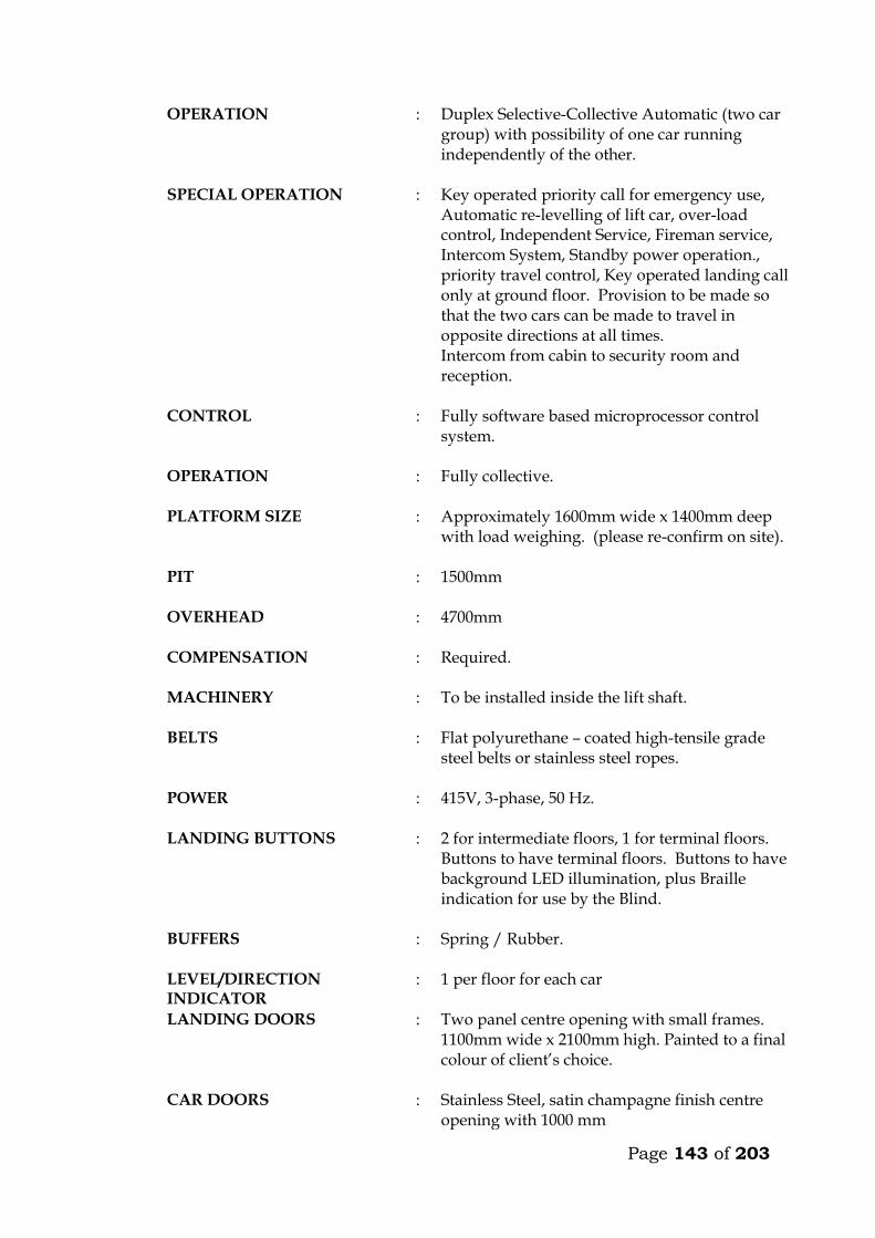
Page 143 of 203
OPERATION : Duplex Selective-Collective Automatic (two car group) with possibility of one car running independently of the other.
SPECIAL OPERATION : Key operated priority call for emergency use, Automatic re-levelling of lift car, over-load control, Independent Service, Fireman service, Intercom System, Standby power operation., priority travel control, Key operated landing call only at ground floor. Provision to be made so that the two cars can be made to travel in opposite directions at all times. Intercom from cabin to security room and reception.
CONTROL : Fully software based microprocessor control system.
OPERATION : Fully collective.
PLATFORM SIZE : Approximately 1600mm wide x 1400mm deep with load weighing. (please re-confirm on site).
PIT : 1500mm
OVERHEAD : 4700mm
COMPENSATION : Required.
MACHINERY : To be installed inside the lift shaft.
BELTS : Flat polyurethane – coated high-tensile grade steel belts or stainless steel ropes.
POWER : 415V, 3-phase, 50 Hz.
LANDING BUTTONS : 2 for intermediate floors, 1 for terminal floors. Buttons to have terminal floors. Buttons to have background LED illumination, plus Braille indication for use by the Blind.
BUFFERS : Spring / Rubber.
LEVEL/DIRECTION INDICATOR
: 1 per floor for each car
LANDING DOORS : Two panel centre opening with small frames. 1100mm wide x 2100mm high. Painted to a final colour of client’s choice.
CAR DOORS : Stainless Steel, satin champagne finish centre opening with 1000 mm
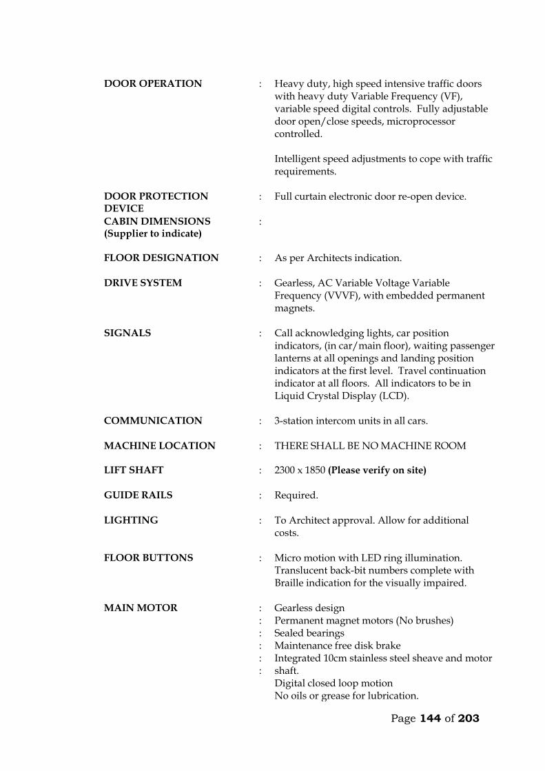
Page 144 of 203
DOOR OPERATION : Heavy duty, high speed intensive traffic doors
with heavy duty Variable Frequency (VF), variable speed digital controls. Fully adjustable door open/close speeds, microprocessor controlled. Intelligent speed adjustments to cope with traffic requirements.
DOOR PROTECTION DEVICE
: Full curtain electronic door re-open device.
CABIN DIMENSIONS (Supplier to indicate)
:
FLOOR DESIGNATION : As per Architects indication.
DRIVE SYSTEM : Gearless, AC Variable Voltage Variable Frequency (VVVF), with embedded permanent magnets.
SIGNALS : Call acknowledging lights, car position indicators, (in car/main floor), waiting passenger lanterns at all openings and landing position indicators at the first level. Travel continuation indicator at all floors. All indicators to be in Liquid Crystal Display (LCD).
COMMUNICATION : 3-station intercom units in all cars.
MACHINE LOCATION
: THERE SHALL BE NO MACHINE ROOM
LIFT SHAFT : 2300 x 1850 (Please verify on site)
GUIDE RAILS : Required.
LIGHTING : To Architect approval. Allow for additional costs.
FLOOR BUTTONS : Micro motion with LED ring illumination. Translucent back-bit numbers complete with Braille indication for the visually impaired.
MAIN MOTOR : : : : : :
Gearless design Permanent magnet motors (No brushes) Sealed bearings Maintenance free disk brake Integrated 10cm stainless steel sheave and motor shaft. Digital closed loop motion No oils or grease for lubrication.
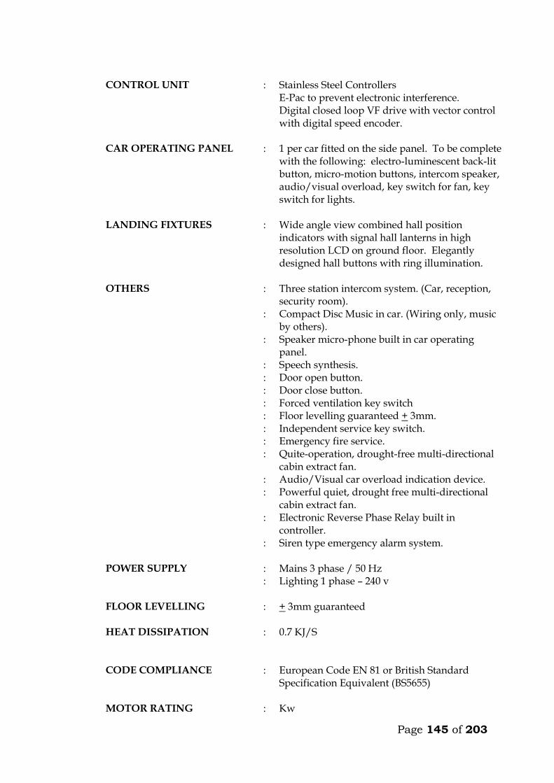
Page 145 of 203
CONTROL UNIT : Stainless Steel Controllers
E-Pac to prevent electronic interference. Digital closed loop VF drive with vector control with digital speed encoder.
CAR OPERATING PANEL : 1 per car fitted on the side panel. To be complete with the following: electro-luminescent back-lit button, micro-motion buttons, intercom speaker, audio/visual overload, key switch for fan, key switch for lights.
LANDING FIXTURES : Wide angle view combined hall position indicators with signal hall lanterns in high resolution LCD on ground floor. Elegantly designed hall buttons with ring illumination.
OTHERS : Three station intercom system. (Car, reception, security room).
: Compact Disc Music in car. (Wiring only, music by others).
: Speaker micro-phone built in car operating panel.
: Speech synthesis. : Door open button. : Door close button. : Forced ventilation key switch : Floor levelling guaranteed + 3mm. : Independent service key switch. : Emergency fire service. : Quite-operation, drought-free multi-directional
cabin extract fan. : Audio/Visual car overload indication device. : Powerful quiet, drought free multi-directional
cabin extract fan. : Electronic Reverse Phase Relay built in
controller. : Siren type emergency alarm system.
POWER SUPPLY :
: Mains 3 phase / 50 Hz Lighting 1 phase – 240 v
FLOOR LEVELLING : + 3mm guaranteed
HEAT DISSIPATION : 0.7 KJ/S
CODE COMPLIANCE : European Code EN 81 or British Standard Specification Equivalent (BS5655)
MOTOR RATING : Kw
Page 146 of 203
STARTING CURRENT : Amps
NOMINAL CURRENT : Amps
SHEAVE : Stainless Steel
MISCELLANEOUS : Heat sensor in the machine room and controller to shut the car as its safety levels at the next landing.
: Rescue operation during power failure with emergency and inspection panel, to move the car to the next landing in event of power failure.
: Electronic light ray device and infrared curtain on car doors.
: Door lock monitoring to put the car on inspection when safety circuits malfunction.
CODE COMPLIANCE : European Code EN 81. STANDARD : BS 5655 / EN 81
COUNTER WEIGHT : Required.
Immediately after appointment the sub-contractor shall provide to the Engineer a
general arrangement drawing showing important dimensions and weights of the lifts, and submit colour samples for the Engineer’s approval.
The sub-contractor must provide all beams, brackets and fixing devices for fixing of
guide rails, counter weights, buffers, door frames, architraves etc. All fixing devices to be cast in or cut into structural walls shall be supplied and fixed
by the sub-contractor. It is the responsibility of the sub-contractor alone to ensure that such devices are cast in or otherwise fixed in the right position and in a proper manner.
Partitions in the lift well shall be made in steel net or wire mesh, fixed to concrete
beams to be supplied and installed by the sub-contractor. 1.02 WORK BY OTHERS
Excluded from this sub-contract is lighting in the plant room and the electrical power supply which shall be brought up to an isolator and distribution board in the plant room by others. Connection to machinery and for lighting in cars shall be carried out by the lift sub-contractor.
Page 147 of 203
1.03 OPERATION
The cars shall travel at a maximum speed of 1.0m/s in all floors. The car must not start unless the car doors are in a closed position and all landing doors are locked in a closed position. Should the load on the car exceed the maximum load, the car and landing doors are to be prevented from closing. Car levelling shall be within 12mm by means of an automatic self-levelling device. An emergency stop button in the car shall stop the car completely even after the button is released. Re-starting shall take place only by activation of a push button in the car and not by a call from any landing. Terminal limit switches must stop the car automatically at the terminal landings. Final limit switches must cut off power and apply the brake automatically, should the car pass the terminal landings. The installation must be provided with a complete controller device to control starting, stopping and speed as well as emergency stopping of the car in case any of the safety devices do not operate or excessive descending or ascending speed is attained by cutting off power to the motor and activation of the brake. Calls in the car must be given preference over calls from landings. At ground floor, calls shall be by means of a key operated switch only for authorised people. The cars must deal with calls in sequence and not be intercepted during their trips by additional calls from cars or landings. The lifts must be provided with automatic bypass devices to prevent unnecessary stops when the cars are full. If the cars are idle and a landing button is pressed, the car positioned nearest to the pressed button has to go to the landing. The car must not stop during the “up” trip at any landing in response to a “down” landing call, unless this call is the highest one registered. When the cars at the same time are “up” trip or “down” trip, only the leading car must stop for landing calls. If one of the cars is out of operation the other car has to answer all calls aforesaid. The operation is still to be collective. For inspection purpose a manually operated switch on the controller connected to “up” and “down” direction buttons exposed on the top of the car, must be provided.
Page 148 of 203
This switch must permit the car to be operated at slow speed from the top of the car. During this inspection the car must not respond to any calls. Provision to be made in the controls so that the cars can travel permanently in opposite directions when required.
1.04 CARS The car frame which supports the car platform and enclosure shall be made of solid
structural steel with welded, bolted or riveted joints. Bolts used must be positioned for easy adjustment. Car finishes shall be :-
FLOOR FINISH : Granite Tiles finish to match lift lobby and
to architects approval. Other preferred finishes may be substituted.
REAR – WALLS : Full View (Panoramic).
HANDRAIL : On 3 walls to be stainless steel satin sloped fittings.
SIDE WALLS : Stainless Steel, satin champagne finish CAR DOORS : Stainless Steel, satin champagne finish LANDING DOORS : Stainless Steel, satin finish.
CEILING : Curved or Flat ceiling to be approved by
the architect including lighting. To be fitted with a silent exhaust fan yielding approximately 650 m³/hr. Allow for any additional costs.
LIGHTING : To be chosen by the Architect. Allow for additional costs.
The colour and type of finishes shall be approved by the Architect before ordering. Each car shall be equipped with 2 sets of illuminated push or touch buttons in silver
anodized or stainless steel flush mounted operating panels. Two car operating panels shall be provided in each car.
The operating panels in all cars must comprise : . Floor buttons, one of each floor served . Emergency call button . Car inspection switch . Emergency stop button
Page 149 of 203
Each car shall have direction of travel indicators at high level opposite doors. Each car shall also be equipped with a digital floor position indicator above the
sliding doors. All lamps, buttons, etc., must be changeable from within the car. All material used shall be approved by the local fire authority. A load plate shall also be fitted in the car showing the maximum load allowed, in
kilograms and number of passengers. 1.05 DOORS AND ARCHITRAVES The entrance to the car to be provided with two panel automatic centre opening
stainless steel, satin finished sliding doors, guided at the bottom by non-metallic shoes sliding in suitable grooves. Doors are to be installed both in car and landings. The doors must be complete with electronic mechanical interlock and emergency opening key.
The car must be stopped and prevented from moving should a door be forced open. The car doors and the landing doors must open automatically when levelling, the
opening to start as the car is approximately 250mm from the landing. The car door and landing door to move simultaneously in opening and closing, being 5 seconds (to be adjustable). In open position the doors automatically have to move back to locked position, even if the car is stationary at the landing. By means of sensitive edge and one photocell the doors have to stop and reverse during their closing cycle if obstructed.
All door panels in landings and cars (like all walls) to be made from materials
described earlier. All architraves to be made from spray painted matt finish steel. All plugs, brackets, etc., for architrave-fixing to be provided by the sub-contractor, and cast in by the sub-contractor. The appearance of the cabin will have to be approved by the Architect before ordering.
It is emphasized that great importance is attached to silent functioning of the doors.
1.06 LANDING CALL BUTTONS At each mid-landing, two stainless steel flush-mounted panels, per car, with two
push or touch buttons for “up” and “down” traffic shall be provided between the landing doors. The buttons must light up when a call is registered.
Direction arrow lights shall be incorporated in all landing call panels, arranged so
that when a button is pressed the corresponding arrow will illuminate indicating the direction of the call which is registered.
At terminal landings one button only to be installed in each landing panel.
Page 150 of 203
At ground floor two illuminated digital car travel position indicators with arrows shall be placed, one above each door.
1.07 SHAFT INSTALLATIONS Guide rails for cars and counterweights to be T-steel guide rails planed on three
edges. Rails must be placed accurately and fixed firmly to the shaft walls with sufficient spacing between brackets. The rails shall be brought totally to the bottom of the shaft.
The fixing of rails and the connection between two or more sections of rail must be in
such a manner that the straight and vertical position is not influenced by changes in temperature or ordinary settlement in the structure.
Guide rails for the car to be either rubber roller guides or Telfon (Tufnol). Roller and
shoes shall be renewable. Buffer must be provided to bring the car counterweight to rest at the extreme limits
of travel, should the car for any reason pass the limit switches. The guide rails, roller shoes, buffers, counter-weight all to be provided and installed
by the Sub-contractor. 1.08 LIFTING MACHINERY
The machine shall be gearless, single wrap traction type, mounted on steel beams fitted on the shaft walls. The beams to be as per structural engineers details. The following information on the machinery must accompany the tender. Make Size, h.p. Voltage, V Power consumption at full load, KW Revolutions per minute, r.p.m. Full load current, A Starting current, A Duration of starting current, sec
Power factor, cos Acceleration time, sec Retardation time, sec The motor must be provided with overload and phase failure cutout devices. The control system to be fitted with a special batter/charger to enable technicians to move cabin to the nearest level to release trapped passengers in case of power failure. The system must prevent engaging of the turning device, until the power supply for the motor is switched off. The aggregate must be dimensioned for the full load in continuous operation and for a temporary overload of 10%. The sub-contractor must provide information on the
Page 151 of 203
highest permissible operating temperature for optional functioning of the lift, and about the heat produced by the entire installation.
1.09 ROPES AND SHEAVES The lifts shall be provided with durable, flat polyurethane-coated high-tensile steel
belts. Ropes maybe substituted but subject to engineers approval. The sheaves shall be of ample diameter for ropes used. Sheaves shall be fixed by
means of iron beams which are supplied and installed by the sub-contractor. Beams must be sound insulated from structural parts.
1.10 ELECTRICAL INSTALLATION All motors and switchgear shall be rated for operation at 240V/415V, 50 cycles.
Relays and components must be tropicalised. The installation must comply with the IEE Regulations. All wiring shall be carried
out in a neat and orderly manner. Cables run on walls or ceilings to be in straight line and right angle bends enclosed in steel ducting.
Connections to equipment more than 400mm from wall shall be run from the wall in
conduit cast in the floor to a connector box fixed upright adjacent to the equipment and through flexible conduit to the equipment.
All electrical switchgear must be clearly labelled. 1.11 ALARM
An alarm button in the car shall simultaneously activate a bell situated on the car and bell positioned at the security station near the lift lobby at ground floor. The bells shall be supplied with power from a rechargeable dry cell battery supplied by sub-contractor. All wiring and installation of the alarm system shall be done by the sub-contractor.
1.12 CONTROL AND DISPLAY SYSTEM A control and display system shall be provided at the security room. The system, comprising a colour video monitor and keyboard shall indicate real-time elevator status, passenger traffic and demand, etc. It shall also be possible to feed commands to the controller from the keyboard, to adjust operation of the cars and for faults diagnosis.

Page 152 of 203
TECHNICAL DETAILS OF LIFTS OFFERED BY THE TENDERER 15. Lifting Machinery
a) Make b) Size, h.p. c) Power consumption at full load, KW d) Revolutions per minute, r.p.m. e) Full load current, A f) Starting current, A g) Duration of starting current, sec
h) Power factor, cos i) Acceleration time, sec j) Retardation time, sec
16. Delivery Details
Time in weeks from acceptance of tender to delivery of all equipment on site ________ Weeks.
Time in weeks from acceptance of tender to installation and commissioning _________ Weeks. 3. Deviations from the Specification
The Tenderer shall give below details of any Specification, or any deviations, omissions, additions of alternatives in respect of the lifts which he is offering. If none, write None.

Page 153 of 203
MAINTENANCE CONTRACT The Tenderer shall insert in this section the cost of a fully comprehensive Maintenance Contract after one of the initial 12 months maintenance or defects liability period. The sum to be inclusive of regular monthly inspection and breakdown service, and shall include for all tools, parts replacement and service material such as oils, lubricants, etc. ITEM KSHS. Annual Maintenance cost for 2 No. lifts as described
in the following pages inclusive of all spares and 24 hour call services (start date assumed end of building contract). _______________ WARRANTY The warranty period for the equipment and all the associated accessories shall be _______________ months from the date of commissioning. (A minimum of 12 months will be allowed). FOREIGN CURRENCY State the foreign currency applied and the exchange rate to the Kenya Shilling. 1 ____________________ (Foreign Currency) = _____________________ KSh.
Page 154 of 203
I: TECHNICAL SPECIFICATION FOR PASSENGER LIFTS INSTALLATIONS FOR SCHEDULE OF RATE 1.01 EXTENT OF WORK This Sub-contract shall include for supply of the lifts equipment, labour, installation,
fixing, connecting, commissioning and delivering up clean and in working order in every detail the following lift installation. The supplier will be liable for installing, setting to work and maintaining for a period of one year after commissioning of the lifts.
QUANTITY : one (1)
TYPE : Single Wrap Traction Passenger Lifts, Machine room-less
CABIN : : : : : : : :
Luxury Car Panoramic (Full view for the back) Refer to the attached drawings Curved or Flat Ceiling to Architects approval Granite Tiles finish to match lift lobby and to architects approval. Other preferred finishes may be substituted. Car Operating Panel to match the side wall panel Round Sectioned Stainless Steel hand-rails with satin sloped fittings Cabin Skirting to ne Stainless Steel Satin Champagne Stainless steel, satin champagne finish car door panels and car façade One half button riser with ring illuminated micro-motion sensors.
CAPACITY : 800Kg, 10 persons
DRIVE : Gear-less, VVVF
SPEED : 1.0 m/s
STARTS/HR : 180
NUMBER OF STOPS/OPENINGS
: 4/4
NUMBER OF OPENINGS : Four openings in line for each lift.
TRAVEL HEIGHT : 12.2 metres (please verify on site)
OPERATION : Duplex Selective-Collective Automatic (two car group) with possibility of one car running independently of the other.
Page 155 of 203
SPECIAL OPERATION : Key operated priority call for emergency use,
Automatic re-levelling of lift car, over-load control, Independent Service, Fireman service, Intercom System, Standby power operation., priority travel control, Key operated landing call only at ground floor. Provision to be made so that the two cars can be made to travel in opposite directions at all times. Intercom from cabin to security room and reception.
CONTROL : Fully software based microprocessor control system.
OPERATION : Fully collective.
PLATFORM SIZE : Approximately 1600mm wide x 1400mm deep with load weighing. (please re-confirm on site).
PIT : 1500mm
OVERHEAD : 4700mm
COMPENSATION : Required.
MACHINERY : To be installed inside the lift shaft.
BELTS : Flat polyurethane – coated high-tensile grade steel belts or stainless steel ropes.
POWER : 415V, 3-phase, 50 Hz.
LANDING BUTTONS : 2 for intermediate floors, 1 for terminal floors. Buttons to have terminal floors. Buttons to have background LED illumination, plus Braille indication for use by the Blind.
BUFFERS : Spring / Rubber.
LEVEL/DIRECTION INDICATOR
: 1 per floor for each car
LANDING DOORS : Two panel centre opening with small frames. 1100mm wide x 2100mm high. Painted to a final colour of client’s choice.
CAR DOORS : Stainless Steel, satin champagne finish centre opening with 1000 mm
DOOR OPERATION : Heavy duty, high speed intensive traffic doors with heavy duty Variable Frequency (VF),
Page 156 of 203
variable speed digital controls. Fully adjustable door open/close speeds, microprocessor controlled. Intelligent speed adjustments to cope with traffic requirements.
DOOR PROTECTION DEVICE
: Full curtain electronic door re-open device.
CABIN DIMENSIONS (Supplier to indicate)
:
FLOOR DESIGNATION : As per Architects indication.
DRIVE SYSTEM : Gearless, AC Variable Voltage Variable Frequency (VVVF), with embedded permanent magnets.
SIGNALS : Call acknowledging lights, car position indicators, (in car/main floor), waiting passenger lanterns at all openings and landing position indicators at the first level. Travel continuation indicator at all floors. All indicators to be in Liquid Crystal Display (LCD).
COMMUNICATION : 3-station intercom units in all cars.
MACHINE LOCATION
: THERE SHALL BE NO MACHINE ROOM
LIFT SHAFT : 2300 x 1850 (Please verify on site)
GUIDE RAILS : Required.
LIGHTING : To Architect approval. Allow for additional costs.
FLOOR BUTTONS : Micro motion with LED ring illumination. Translucent back-bit numbers complete with Braille indication for the visually impaired.
MAIN MOTOR : : : : : :
Gearless design Permanent magnet motors (No brushes) Sealed bearings Maintenance free disk brake Integrated 10cm stainless steel sheave and motor shaft. Digital closed loop motion No oils or grease for lubrication.
CONTROL UNIT : Stainless Steel Controllers E-Pac to prevent electronic interference.
Page 157 of 203
Digital closed loop VF drive with vector control with digital speed encoder.
CAR OPERATING PANEL : 1 per car fitted on the side panel. To be complete with the following: electro-luminescent back-lit button, micro-motion buttons, intercom speaker, audio/visual overload, key switch for fan, key switch for lights.
LANDING FIXTURES : Wide angle view combined hall position indicators with signal hall lanterns in high resolution LCD on ground floor. Elegantly designed hall buttons with ring illumination.
OTHERS : Three station intercom system. (Car, reception, security room).
: Compact Disc Music in car. (Wiring only, music by others).
: Speaker micro-phone built in car operating panel.
: Speech synthesis. : Door open button. : Door close button. : Forced ventilation key switch : Floor levelling guaranteed + 3mm. : Independent service key switch. : Emergency fire service. : Quite-operation, drought-free multi-directional
cabin extract fan. : Audio/Visual car overload indication device. : Powerful quiet, drought free multi-directional
cabin extract fan. : Electronic Reverse Phase Relay built in
controller. : Siren type emergency alarm system.
POWER SUPPLY :
: Mains 3 phase / 50 Hz Lighting 1 phase – 240 v
FLOOR LEVELLING : + 3mm guaranteed
HEAT DISSIPATION : 0.7 KJ/S
CODE COMPLIANCE : European Code EN 81 or British Standard Specification Equivalent (BS5655)
MOTOR RATING : Kw
STARTING CURRENT : Amps
Page 158 of 203
NOMINAL CURRENT : Amps
SHEAVE : Stainless Steel
MISCELLANEOUS : Heat sensor in the machine room and controller to shut the car as its safety levels at the next landing.
: Rescue operation during power failure with emergency and inspection panel, to move the car to the next landing in event of power failure.
: Electronic light ray device and infrared curtain on car doors.
: Door lock monitoring to put the car on inspection when safety circuits malfunction.
CODE COMPLIANCE : European Code EN 81. STANDARD : BS 5655 / EN 81
COUNTER WEIGHT : Required.
Immediately after appointment the sub-contractor shall provide to the Engineer a
general arrangement drawing showing important dimensions and weights of the lifts, and submit colour samples for the Engineer’s approval.
The sub-contractor must provide all beams, brackets and fixing devices for fixing of
guide rails, counter weights, buffers, door frames, architraves etc. All fixing devices to be cast in or cut into structural walls shall be supplied and fixed
by the sub-contractor. It is the responsibility of the sub-contractor alone to ensure that such devices are cast in or otherwise fixed in the right position and in a proper manner.
Partitions in the lift well shall be made in steel net or wire mesh, fixed to concrete
beams to be supplied and installed by the sub-contractor. 1.02 WORK BY OTHERS
Excluded from this sub-contract is lighting in the plant room and the electrical power supply which shall be brought up to an isolator and distribution board in the plant room by others. Connection to machinery and for lighting in cars shall be carried out by the lift sub-contractor.
1.03 OPERATION
The cars shall travel at a maximum speed of 1.0m/s in all floors.
Page 159 of 203
The car must not start unless the car doors are in a closed position and all landing doors are locked in a closed position. Should the load on the car exceed the maximum load, the car and landing doors are to be prevented from closing. Car levelling shall be within 12mm by means of an automatic self-levelling device. An emergency stop button in the car shall stop the car completely even after the button is released. Re-starting shall take place only by activation of a push button in the car and not by a call from any landing. Terminal limit switches must stop the car automatically at the terminal landings. Final limit switches must cut off power and apply the brake automatically, should the car pass the terminal landings. The installation must be provided with a complete controller device to control starting, stopping and speed as well as emergency stopping of the car in case any of the safety devices do not operate or excessive descending or ascending speed is attained by cutting off power to the motor and activation of the brake. Calls in the car must be given preference over calls from landings. At ground floor, calls shall be by means of a key operated switch only for authorised people. The cars must deal with calls in sequence and not be intercepted during their trips by additional calls from cars or landings. The lifts must be provided with automatic bypass devices to prevent unnecessary stops when the cars are full. If the cars are idle and a landing button is pressed, the car positioned nearest to the pressed button has to go to the landing. The car must not stop during the “up” trip at any landing in response to a “down” landing call, unless this call is the highest one registered. When the cars at the same time are “up” trip or “down” trip, only the leading car must stop for landing calls. If one of the cars is out of operation the other car has to answer all calls aforesaid. The operation is still to be collective. For inspection purpose a manually operated switch on the controller connected to “up” and “down” direction buttons exposed on the top of the car, must be provided. This switch must permit the car to be operated at slow speed from the top of the car. During this inspection the car must not respond to any calls. Provision to be made in the controls so that the cars can travel permanently in opposite directions when required.
Page 160 of 203
1.04 CARS The car frame which supports the car platform and enclosure shall be made of solid
structural steel with welded, bolted or riveted joints. Bolts used must be positioned for easy adjustment. Car finishes shall be :-
FLOOR FINISH : Granite Tiles finish to match lift lobby and
to architects approval. Other preferred finishes may be substituted.
REAR – WALLS : Full View (Panoramic).
HANDRAIL : On 3 walls to be stainless steel satin sloped fittings.
SIDE WALLS : Stainless Steel, satin champagne finish CAR DOORS : Stainless Steel, satin champagne finish LANDING DOORS : Stainless Steel, satin finish.
CEILING : Curved or Flat ceiling to be approved by
the architect including lighting. To be fitted with a silent exhaust fan yielding approximately 650 m³/hr. Allow for any additional costs.
LIGHTING : To be chosen by the Architect. Allow for additional costs.
The colour and type of finishes shall be approved by the Architect before ordering. Each car shall be equipped with 2 sets of illuminated push or touch buttons in silver
anodized or stainless steel flush mounted operating panels. Two car operating panels shall be provided in each car.
The operating panels in all cars must comprise : . Floor buttons, one of each floor served . Emergency call button . Car inspection switch . Emergency stop button Each car shall have direction of travel indicators at high level opposite doors. Each car shall also be equipped with a digital floor position indicator above the
sliding doors. All lamps, buttons, etc., must be changeable from within the car.
Page 161 of 203
All material used shall be approved by the local fire authority. A load plate shall also be fitted in the car showing the maximum load allowed, in
kilograms and number of passengers. 1.05 DOORS AND ARCHITRAVES The entrance to the car to be provided with two panel automatic centre opening
stainless steel, satin finished sliding doors, guided at the bottom by non-metallic shoes sliding in suitable grooves. Doors are to be installed both in car and landings. The doors must be complete with electronic mechanical interlock and emergency opening key.
The car must be stopped and prevented from moving should a door be forced open. The car doors and the landing doors must open automatically when levelling, the
opening to start as the car is approximately 250mm from the landing. The car door and landing door to move simultaneously in opening and closing, being 5 seconds (to be adjustable). In open position the doors automatically have to move back to locked position, even if the car is stationary at the landing. By means of sensitive edge and one photocell the doors have to stop and reverse during their closing cycle if obstructed.
All door panels in landings and cars (like all walls) to be made from materials
described earlier. All architraves to be made from spray painted matt finish steel. All plugs, brackets, etc., for architrave-fixing to be provided by the sub-contractor, and cast in by the sub-contractor. The appearance of the cabin will have to be approved by the Architect before ordering.
It is emphasized that great importance is attached to silent functioning of the doors.
1.06 LANDING CALL BUTTONS At each mid-landing, two stainless steel flush-mounted panels, per car, with two
push or touch buttons for “up” and “down” traffic shall be provided between the landing doors. The buttons must light up when a call is registered.
Direction arrow lights shall be incorporated in all landing call panels, arranged so
that when a button is pressed the corresponding arrow will illuminate indicating the direction of the call which is registered.
At terminal landings one button only to be installed in each landing panel. At ground floor two illuminated digital car travel position indicators with arrows
shall be placed, one above each door. 1.07 SHAFT INSTALLATIONS Guide rails for cars and counterweights to be T-steel guide rails planed on three
edges. Rails must be placed accurately and fixed firmly to the shaft walls with
Page 162 of 203
sufficient spacing between brackets. The rails shall be brought totally to the bottom of the shaft.
The fixing of rails and the connection between two or more sections of rail must be in
such a manner that the straight and vertical position is not influenced by changes in temperature or ordinary settlement in the structure.
Guide rails for the car to be either rubber roller guides or Telfon (Tufnol). Roller and
shoes shall be renewable. Buffer must be provided to bring the car counterweight to rest at the extreme limits
of travel, should the car for any reason pass the limit switches. The guide rails, roller shoes, buffers, counter-weight all to be provided and installed
by the Sub-contractor. 1.08 LIFTING MACHINERY
The machine shall be gearless, single wrap traction type, mounted on steel beams fitted on the shaft walls. The beams to be as per structural engineers details. The following information on the machinery must accompany the tender. Make Size, h.p. Voltage, V Power consumption at full load, KW Revolutions per minute, r.p.m. Full load current, A Starting current, A Duration of starting current, sec
Power factor, cos Acceleration time, sec Retardation time, sec The motor must be provided with overload and phase failure cutout devices. The control system to be fitted with a special batter/charger to enable technicians to move cabin to the nearest level to release trapped passengers in case of power failure. The system must prevent engaging of the turning device, until the power supply for the motor is switched off. The aggregate must be dimensioned for the full load in continuous operation and for a temporary overload of 10%. The sub-contractor must provide information on the highest permissible operating temperature for optional functioning of the lift, and about the heat produced by the entire installation.
1.09 ROPES AND SHEAVES The lifts shall be provided with durable, flat polyurethane-coated high-tensile steel
belts. Ropes maybe substituted but subject to engineers approval.
Page 163 of 203
The sheaves shall be of ample diameter for ropes used. Sheaves shall be fixed by
means of iron beams which are supplied and installed by the sub-contractor. Beams must be sound insulated from structural parts.
1.10 ELECTRICAL INSTALLATION All motors and switchgear shall be rated for operation at 240V/415V, 50 cycles.
Relays and components must be tropicalised. The installation must comply with the IEE Regulations. All wiring shall be carried
out in a neat and orderly manner. Cables run on walls or ceilings to be in straight line and right angle bends enclosed in steel ducting.
Connections to equipment more than 400mm from wall shall be run from the wall in
conduit cast in the floor to a connector box fixed upright adjacent to the equipment and through flexible conduit to the equipment.
All electrical switchgear must be clearly labelled. 1.11 ALARM
An alarm button in the car shall simultaneously activate a bell situated on the car and bell positioned at the security station near the lift lobby at ground floor. The bells shall be supplied with power from a rechargeable dry cell battery supplied by sub-contractor. All wiring and installation of the alarm system shall be done by the sub-contractor.
1.12 CONTROL AND DISPLAY SYSTEM A control and display system shall be provided at the security room. The system, comprising a colour video monitor and keyboard shall indicate real-time elevator status, passenger traffic and demand, etc. It shall also be possible to feed commands to the controller from the keyboard, to adjust operation of the cars and for faults diagnosis.

Page 164 of 203
TECHNICAL DETAILS OF LIFTS OFFERED BY THE TENDERER 17. Lifting Machinery
a) Make b) Size, h.p. c) Power consumption at full load, KW d) Revolutions per minute, r.p.m. e) Full load current, A f) Starting current, A g) Duration of starting current, sec
h) Power factor, cos i) Acceleration time, sec j) Retardation time, sec
18. Delivery Details
Time in weeks from acceptance of tender to delivery of all equipment on site ________ Weeks.
Time in weeks from acceptance of tender to installation and commissioning _________ Weeks. 3. Deviations from the Specification
The Tenderer shall give below details of any Specification, or any deviations, omissions, additions of alternatives in respect of the lifts which he is offering. If none, write None.

Page 165 of 203
MAINTENANCE CONTRACT The Tenderer shall insert in this section the cost of a fully comprehensive Maintenance Contract after one of the initial 12 months maintenance or defects liability period. The sum to be inclusive of regular monthly inspection and breakdown service, and shall include for all tools, parts replacement and service material such as oils, lubricants, etc. ITEM KSHS. Annual Maintenance cost for 1 No. lifts as described
in the following pages inclusive of all spares and 24 hour call services (start date assumed end of building contract). _______________ WARRANTY The warranty period for the equipment and all the associated accessories shall be _______________ months from the date of commissioning. (A minimum of 12 months will be allowed). FOREIGN CURRENCY State the foreign currency applied and the exchange rate to the Kenya Shilling. 1 ____________________ (Foreign Currency) = _____________________ KSh.
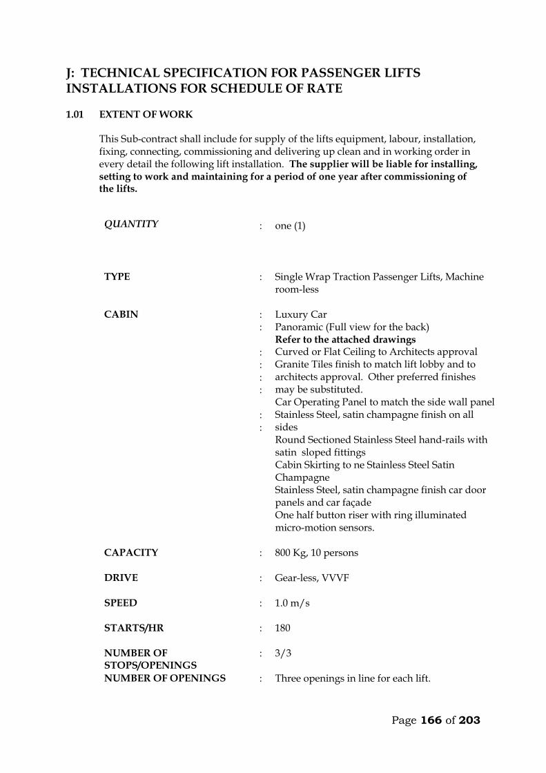
Page 166 of 203
J: TECHNICAL SPECIFICATION FOR PASSENGER LIFTS INSTALLATIONS FOR SCHEDULE OF RATE 1.01 EXTENT OF WORK This Sub-contract shall include for supply of the lifts equipment, labour, installation,
fixing, connecting, commissioning and delivering up clean and in working order in every detail the following lift installation. The supplier will be liable for installing, setting to work and maintaining for a period of one year after commissioning of the lifts.
QUANTITY :
one (1)
TYPE : Single Wrap Traction Passenger Lifts, Machine room-less
CABIN
: : : : : : : :
Luxury Car Panoramic (Full view for the back) Refer to the attached drawings Curved or Flat Ceiling to Architects approval Granite Tiles finish to match lift lobby and to architects approval. Other preferred finishes may be substituted. Car Operating Panel to match the side wall panel Stainless Steel, satin champagne finish on all sides Round Sectioned Stainless Steel hand-rails with satin sloped fittings Cabin Skirting to ne Stainless Steel Satin Champagne Stainless Steel, satin champagne finish car door panels and car façade One half button riser with ring illuminated micro-motion sensors.
CAPACITY : 800 Kg, 10 persons
DRIVE : Gear-less, VVVF
SPEED : 1.0 m/s
STARTS/HR : 180
NUMBER OF STOPS/OPENINGS
: 3/3
NUMBER OF OPENINGS : Three openings in line for each lift.
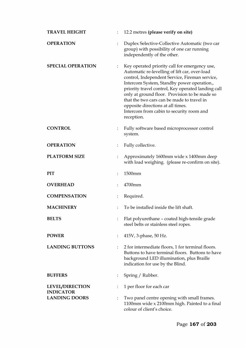
Page 167 of 203
TRAVEL HEIGHT : 12.2 metres (please verify on site)
OPERATION : Duplex Selective-Collective Automatic (two car group) with possibility of one car running independently of the other.
SPECIAL OPERATION : Key operated priority call for emergency use, Automatic re-levelling of lift car, over-load control, Independent Service, Fireman service, Intercom System, Standby power operation., priority travel control, Key operated landing call only at ground floor. Provision to be made so that the two cars can be made to travel in opposite directions at all times. Intercom from cabin to security room and reception.
CONTROL : Fully software based microprocessor control system.
OPERATION : Fully collective.
PLATFORM SIZE : Approximately 1600mm wide x 1400mm deep with load weighing. (please re-confirm on site).
PIT : 1500mm
OVERHEAD : 4700mm
COMPENSATION : Required.
MACHINERY : To be installed inside the lift shaft.
BELTS : Flat polyurethane – coated high-tensile grade steel belts or stainless steel ropes.
POWER : 415V, 3-phase, 50 Hz.
LANDING BUTTONS : 2 for intermediate floors, 1 for terminal floors. Buttons to have terminal floors. Buttons to have background LED illumination, plus Braille indication for use by the Blind.
BUFFERS : Spring / Rubber.
LEVEL/DIRECTION INDICATOR
: 1 per floor for each car
LANDING DOORS : Two panel centre opening with small frames. 1100mm wide x 2100mm high. Painted to a final colour of client’s choice.
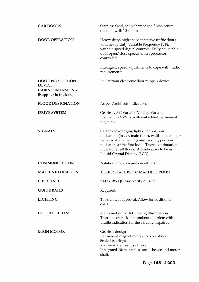
Page 168 of 203
CAR DOORS : Stainless Steel, satin champagne finish centre opening with 1000 mm
DOOR OPERATION : Heavy duty, high speed intensive traffic doors with heavy duty Variable Frequency (VF), variable speed digital controls. Fully adjustable door open/close speeds, microprocessor controlled. Intelligent speed adjustments to cope with traffic requirements.
DOOR PROTECTION DEVICE
: Full curtain electronic door re-open device.
CABIN DIMENSIONS (Supplier to indicate)
:
FLOOR DESIGNATION : As per Architects indication.
DRIVE SYSTEM : Gearless, AC Variable Voltage Variable Frequency (VVVF), with embedded permanent magnets.
SIGNALS : Call acknowledging lights, car position indicators, (in car/main floor), waiting passenger lanterns at all openings and landing position indicators at the first level. Travel continuation indicator at all floors. All indicators to be in Liquid Crystal Display (LCD).
COMMUNICATION : 3-station intercom units in all cars.
MACHINE LOCATION
: THERE SHALL BE NO MACHINE ROOM
LIFT SHAFT : 2300 x 1850 (Please verify on site)
GUIDE RAILS : Required.
LIGHTING : To Architect approval. Allow for additional costs.
FLOOR BUTTONS : Micro motion with LED ring illumination. Translucent back-bit numbers complete with Braille indication for the visually impaired.
MAIN MOTOR : : : : : :
Gearless design Permanent magnet motors (No brushes) Sealed bearings Maintenance free disk brake Integrated 10cm stainless steel sheave and motor shaft.
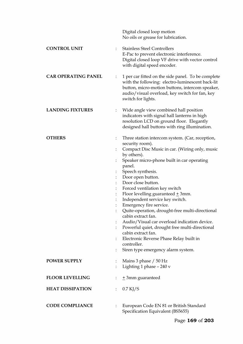
Page 169 of 203
Digital closed loop motion No oils or grease for lubrication.
CONTROL UNIT : Stainless Steel Controllers E-Pac to prevent electronic interference. Digital closed loop VF drive with vector control with digital speed encoder.
CAR OPERATING PANEL : 1 per car fitted on the side panel. To be complete with the following: electro-luminescent back-lit button, micro-motion buttons, intercom speaker, audio/visual overload, key switch for fan, key switch for lights.
LANDING FIXTURES : Wide angle view combined hall position indicators with signal hall lanterns in high resolution LCD on ground floor. Elegantly designed hall buttons with ring illumination.
OTHERS : Three station intercom system. (Car, reception, security room).
: Compact Disc Music in car. (Wiring only, music by others).
: Speaker micro-phone built in car operating panel.
: Speech synthesis. : Door open button. : Door close button. : Forced ventilation key switch : Floor levelling guaranteed + 3mm. : Independent service key switch. : Emergency fire service. : Quite-operation, drought-free multi-directional
cabin extract fan. : Audio/Visual car overload indication device. : Powerful quiet, drought free multi-directional
cabin extract fan. : Electronic Reverse Phase Relay built in
controller. : Siren type emergency alarm system.
POWER SUPPLY :
: Mains 3 phase / 50 Hz Lighting 1 phase – 240 v
FLOOR LEVELLING : + 3mm guaranteed
HEAT DISSIPATION : 0.7 KJ/S
CODE COMPLIANCE : European Code EN 81 or British Standard Specification Equivalent (BS5655)
Page 170 of 203
MOTOR RATING : Kw
STARTING CURRENT : Amps
NOMINAL CURRENT : Amps
SHEAVE : Stainless Steel
MISCELLANEOUS : Heat sensor in the machine room and controller
to shut the car as its safety levels at the next landing.
: Rescue operation during power failure with emergency and inspection panel, to move the car to the next landing in event of power failure.
: Electronic light ray device and infrared curtain on car doors.
: Door lock monitoring to put the car on inspection when safety circuits malfunction.
CODE COMPLIANCE : European Code EN 81. STANDARD : BS 5655 / EN 81
COUNTER WEIGHT : Required.
Immediately after appointment the sub-contractor shall provide to the Engineer a
general arrangement drawing showing important dimensions and weights of the lifts, and submit colour samples for the Engineer’s approval.
The sub-contractor must provide all beams, brackets and fixing devices for fixing of
guide rails, counter weights, buffers, door frames, architraves etc. All fixing devices to be cast in or cut into structural walls shall be supplied and fixed
by the sub-contractor. It is the responsibility of the sub-contractor alone to ensure that such devices are cast in or otherwise fixed in the right position and in a proper manner.
Partitions in the lift well shall be made in steel net or wire mesh, fixed to concrete
beams to be supplied and installed by the sub-contractor. 1.02 WORK BY OTHERS
Excluded from this sub-contract is lighting in the plant room and the electrical power supply which shall be brought up to an isolator and distribution board in the plant room by others. Connection to machinery and for lighting in cars shall be carried out by the lift sub-contractor.
Page 171 of 203
1.03 OPERATION
The cars shall travel at a maximum speed of 1.0m/s in all floors. The car must not start unless the car doors are in a closed position and all landing doors are locked in a closed position. Should the load on the car exceed the maximum load, the car and landing doors are to be prevented from closing. Car levelling shall be within 12mm by means of an automatic self-levelling device. An emergency stop button in the car shall stop the car completely even after the button is released. Re-starting shall take place only by activation of a push button in the car and not by a call from any landing. Terminal limit switches must stop the car automatically at the terminal landings. Final limit switches must cut off power and apply the brake automatically, should the car pass the terminal landings. The installation must be provided with a complete controller device to control starting, stopping and speed as well as emergency stopping of the car in case any of the safety devices do not operate or excessive descending or ascending speed is attained by cutting off power to the motor and activation of the brake. Calls in the car must be given preference over calls from landings. At ground floor, calls shall be by means of a key operated switch only for authorised people. The cars must deal with calls in sequence and not be intercepted during their trips by additional calls from cars or landings. The lifts must be provided with automatic bypass devices to prevent unnecessary stops when the cars are full. If the cars are idle and a landing button is pressed, the car positioned nearest to the pressed button has to go to the landing. The car must not stop during the “up” trip at any landing in response to a “down” landing call, unless this call is the highest one registered. When the cars at the same time are “up” trip or “down” trip, only the leading car must stop for landing calls. If one of the cars is out of operation the other car has to answer all calls aforesaid. The operation is still to be collective. For inspection purpose a manually operated switch on the controller connected to “up” and “down” direction buttons exposed on the top of the car, must be provided.

Page 172 of 203
This switch must permit the car to be operated at slow speed from the top of the car. During this inspection the car must not respond to any calls. Provision to be made in the controls so that the cars can travel permanently in opposite directions when required.
1.04 CARS The car frame which supports the car platform and enclosure shall be made of solid
structural steel with welded, bolted or riveted joints. Bolts used must be positioned for easy adjustment. Car finishes shall be :-
FLOOR FINISH : Granite Tiles finish to match lift lobby and
to architects approval. Other preferred finishes may be substituted.
REAR – WALLS : Full View (Panoramic).
HANDRAIL : On 3 walls to be stainless steel satin sloped fittings.
SIDE WALLS : Stainless Steel, satin champagne finish CAR DOORS : Stainless Steel, satin champagne finish LANDING DOORS : Stainless Steel, satin finish.
CEILING : Curved or Flat ceiling to be approved by
the architect including lighting. To be fitted with a silent exhaust fan yielding approximately 650 m³/hr. Allow for any additional costs.
LIGHTING : To be chosen by the Architect. Allow for additional costs.
The colour and type of finishes shall be approved by the Architect before ordering. Each car shall be equipped with 2 sets of illuminated push or touch buttons in silver
anodized or stainless steel flush mounted operating panels. Two car operating panels shall be provided in each car.
The operating panels in all cars must comprise : . Floor buttons, one of each floor served . Emergency call button . Car inspection switch . Emergency stop button

Page 173 of 203
Each car shall have direction of travel indicators at high level opposite doors. Each car shall also be equipped with a digital floor position indicator above the
sliding doors. All lamps, buttons, etc., must be changeable from within the car. All material used shall be approved by the local fire authority. A load plate shall also be fitted in the car showing the maximum load allowed, in
kilograms and number of passengers. 1.05 DOORS AND ARCHITRAVES The entrance to the car to be provided with two panel automatic centre opening
stainless steel, satin finished sliding doors, guided at the bottom by non-metallic shoes sliding in suitable grooves. Doors are to be installed both in car and landings. The doors must be complete with electronic mechanical interlock and emergency opening key.
The car must be stopped and prevented from moving should a door be forced open. The car doors and the landing doors must open automatically when levelling, the
opening to start as the car is approximately 250mm from the landing. The car door and landing door to move simultaneously in opening and closing, being 5 seconds (to be adjustable). In open position the doors automatically have to move back to locked position, even if the car is stationary at the landing. By means of sensitive edge and one photocell the doors have to stop and reverse during their closing cycle if obstructed.
All door panels in landings and cars (like all walls) to be made from materials
described earlier. All architraves to be made from spray painted matt finish steel. All plugs, brackets, etc., for architrave-fixing to be provided by the sub-contractor, and cast in by the sub-contractor. The appearance of the cabin will have to be approved by the Architect before ordering.
It is emphasized that great importance is attached to silent functioning of the doors.
1.06 LANDING CALL BUTTONS At each mid-landing, two stainless steel flush-mounted panels, per car, with two
push or touch buttons for “up” and “down” traffic shall be provided between the landing doors. The buttons must light up when a call is registered.
Direction arrow lights shall be incorporated in all landing call panels, arranged so
that when a button is pressed the corresponding arrow will illuminate indicating the direction of the call which is registered.
At terminal landings one button only to be installed in each landing panel.

Page 174 of 203
At ground floor two illuminated digital car travel position indicators with arrows shall be placed, one above each door.
1.07 SHAFT INSTALLATIONS Guide rails for cars and counterweights to be T-steel guide rails planed on three
edges. Rails must be placed accurately and fixed firmly to the shaft walls with sufficient spacing between brackets. The rails shall be brought totally to the bottom of the shaft.
The fixing of rails and the connection between two or more sections of rail must be in
such a manner that the straight and vertical position is not influenced by changes in temperature or ordinary settlement in the structure.
Guide rails for the car to be either rubber roller guides or Telfon (Tufnol). Roller and
shoes shall be renewable. Buffer must be provided to bring the car counterweight to rest at the extreme limits
of travel, should the car for any reason pass the limit switches. The guide rails, roller shoes, buffers, counter-weight all to be provided and installed
by the Sub-contractor. 1.08 LIFTING MACHINERY
The machine shall be gearless, single wrap traction type, mounted on steel beams fitted on the shaft walls. The beams to be as per structural engineers details. The following information on the machinery must accompany the tender. Make Size, h.p. Voltage, V Power consumption at full load, KW Revolutions per minute, r.p.m. Full load current, A Starting current, A Duration of starting current, sec
Power factor, cos Acceleration time, sec Retardation time, sec The motor must be provided with overload and phase failure cutout devices. The control system to be fitted with a special batter/charger to enable technicians to move cabin to the nearest level to release trapped passengers in case of power failure. The system must prevent engaging of the turning device, until the power supply for the motor is switched off. The aggregate must be dimensioned for the full load in continuous operation and for a temporary overload of 10%. The sub-contractor must provide information on the
Page 175 of 203
highest permissible operating temperature for optional functioning of the lift, and about the heat produced by the entire installation.
1.09 ROPES AND SHEAVES The lifts shall be provided with durable, flat polyurethane-coated high-tensile steel
belts. Ropes maybe substituted but subject to engineers approval. The sheaves shall be of ample diameter for ropes used. Sheaves shall be fixed by
means of iron beams which are supplied and installed by the sub-contractor. Beams must be sound insulated from structural parts.
1.10 ELECTRICAL INSTALLATION All motors and switchgear shall be rated for operation at 240V/415V, 50 cycles.
Relays and components must be tropicalised. The installation must comply with the IEE Regulations. All wiring shall be carried
out in a neat and orderly manner. Cables run on walls or ceilings to be in straight line and right angle bends enclosed in steel ducting.
Connections to equipment more than 400mm from wall shall be run from the wall in
conduit cast in the floor to a connector box fixed upright adjacent to the equipment and through flexible conduit to the equipment.
All electrical switchgear must be clearly labelled. 1.11 ALARM
An alarm button in the car shall simultaneously activate a bell situated on the car and bell positioned at the security station near the lift lobby at ground floor. The bells shall be supplied with power from a rechargeable dry cell battery supplied by sub-contractor. All wiring and installation of the alarm system shall be done by the sub-contractor.
1.12 CONTROL AND DISPLAY SYSTEM A control and display system shall be provided at the security room. The system, comprising a colour video monitor and keyboard shall indicate real-time elevator status, passenger traffic and demand, etc. It shall also be possible to feed commands to the controller from the keyboard, to adjust operation of the cars and for faults diagnosis.
Page 176 of 203
TECHNICAL DETAILS OF LIFTS OFFERED BY THE TENDERER 19. Lifting Machinery
a) Make b) Size, h.p. c) Power consumption at full load, KW d) Revolutions per minute, r.p.m. e) Full load current, A f) Starting current, A g) Duration of starting current, sec
h) Power factor, cos i) Acceleration time, sec j) Retardation time, sec k) Certificate of compliance with European standards for passenger/goods
lifts 20. Delivery Details
Time in weeks from acceptance of tender to delivery of all equipment on site ________ Weeks.
Time in weeks from acceptance of tender to installation and commissioning _________ Weeks.
3. Deviations from the Specification
The Tenderer shall give below details of any Specification, or any deviations, omissions, additions of alternatives in respect of the lifts which he is offering. If none, write None.

Page 177 of 203
MAINTENANCE CONTRACT The Tenderer shall insert in this section the cost of a fully comprehensive Maintenance Contract after one of the initial 12 months maintenance or defects liability period. The sum to be inclusive of regular monthly inspection and breakdown service, and shall include for all tools, parts replacement and service material such as oils, lubricants, etc. ITEM KSHS. Annual Maintenance cost for 2 No. lifts as described
in the following pages inclusive of all spares and 24 hour call services (start date assumed end of building contract). _______________ WARRANTY The warranty period for the equipment and all the associated accessories shall be _______________ months from the date of commissioning. (A minimum of 12 months will be allowed). FOREIGN CURRENCY State the foreign currency applied and the exchange rate to the Kenya Shilling. 1 ____________________ (Foreign Currency) = _____________________ KSh.

Page 178 of 203
K: FULL SERVICE MAINTANANCE PER YEAR AFTER EXPIRY OF DEFECTS LIABILITY PERIOD
SPECIAL NOTES 1. The tenderer is advised to note that their price shall be used in the evaluation of the tenders. 2. The tenderer shall price for both labour and consumables (materials) during the 12 months
full service period in appenix A of this section. The price shall be for supply, installation, testing and commissioning including all taxes applicable at the time of tender.
3. The tenderer shall list and price the consumable/ spare parts/ materials to be used during
the 12 months full service period in appenix B of this section. The price shall be for supply, installation, testing and commissioning including all taxes applicable at the time of tender.
4. The tenderer shall list and price the consumable/ spare parts/ materials to be used during
the 12 months full service period. This list is to be comprehensive as possible and shall inculde major spares as cards, fan motors etc. The price shall be for supply, installation, testing and commissioning including all taxes applicable at the time of tender. These are the spare parts that are not required during the normal routine maintenance. These spare parts shall only be paid for as and when repalced. The tenderer shall give the details of these spare parts in in appenix C of this section.
5. The price quoted for the above shall be as per the Standard Maintanance Tender Document. 6. The tenderer shall be required to the sign the 12 Months after Defects Liability Maintanance
Contract based on the price quoted and the Standard Maintanance Tender Document refered to in item 5 above.
7. The tenderer MUST fill all the prices and rates in the Appendices A, B and C of this section.
Failure to do so shall lead to disqualification.

Page 179 of 203
APPENDIX ‘A’
PRICE FOR FULL NORMAL ROUTINE MAINTANANCE PER YEAR AFTER DEFECTS LIABILITY PERIOD
Item Description Kshs Cts
1.0
2.0
Labour costs per month Material costs for spare parts (consumables) per month – see Appendix C of this section
Sub-total for one (1No.) Month Maintenance after the Defects Liability Period ( Not to be carried to Form of Tender)
Grand Total for 12 Months Maintenance after the Defects Liability Period ( Not to be carried to Form of Tender)
Signed by the Tenderer......................................................................... ..................... Official Stamp .......................................................................................................... Date....................................................................................................... .........................
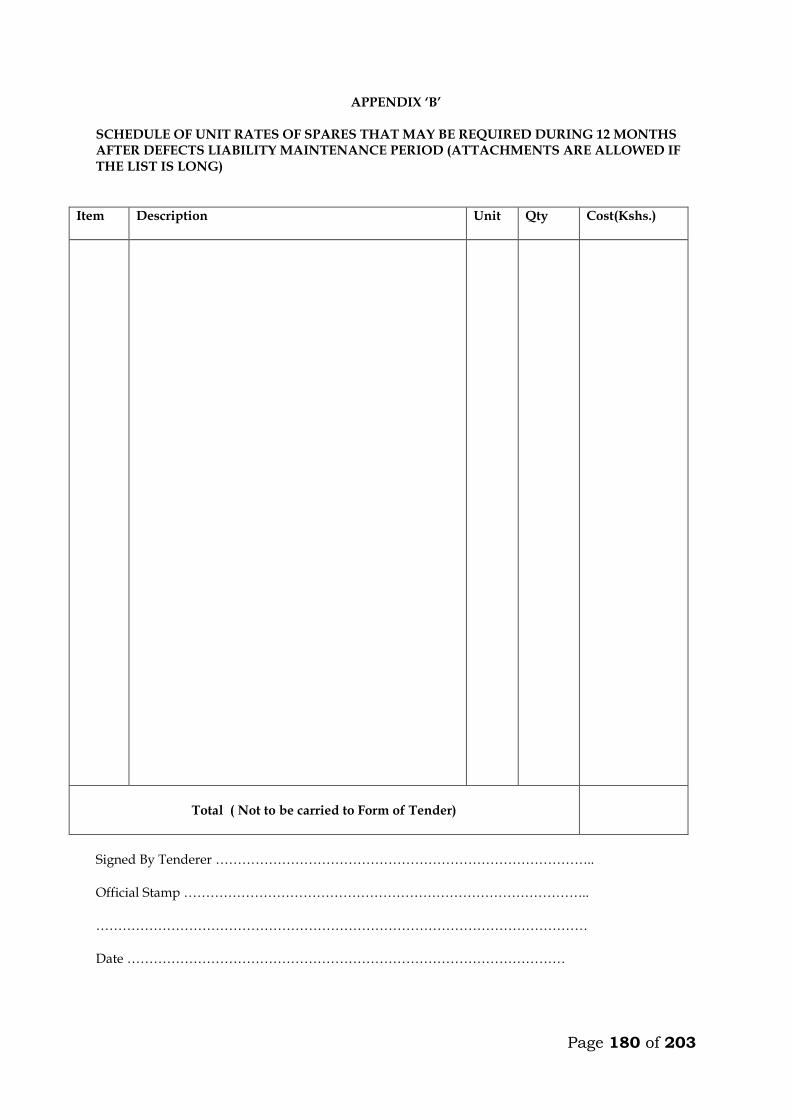
Page 180 of 203
APPENDIX ‘B’
SCHEDULE OF UNIT RATES OF SPARES THAT MAY BE REQUIRED DURING 12 MONTHS AFTER DEFECTS LIABILITY MAINTENANCE PERIOD (ATTACHMENTS ARE ALLOWED IF THE LIST IS LONG)
Item
Description Unit Qty Cost(Kshs.)
Total ( Not to be carried to Form of Tender)
Signed By Tenderer ………………………………………………………………………….. Official Stamp ……………………………………………………………………………….. ………………………………………………………………………………………………… Date ………………………………………………………………………………………
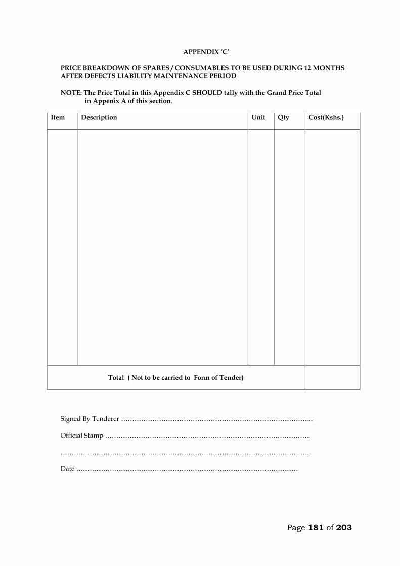
Page 181 of 203
APPENDIX ‘C’
PRICE BREAKDOWN OF SPARES / CONSUMABLES TO BE USED DURING 12 MONTHS AFTER DEFECTS LIABILITY MAINTENANCE PERIOD
NOTE: The Price Total in this Appendix C SHOULD tally with the Grand Price Total
in Appenix A of this section.
Item
Description Unit Qty Cost(Kshs.)
Total ( Not to be carried to Form of Tender)
Signed By Tenderer ………………………………………………………………………….. Official Stamp ……………………………………………………………………………….. ………………………………………………………………………………………………… Date ………………………………………………………………………………………

Page 182 of 203
PART N: TECHNICAL SCHEDULE OF ITEMS TO BE SUPPLIED
CONTENTS
CLAUSE NO. DESCRIPTION PAGE
1. GENERAL NOTES TO TENDERERS M3
2. TECHNICAL SCHEDULE M4
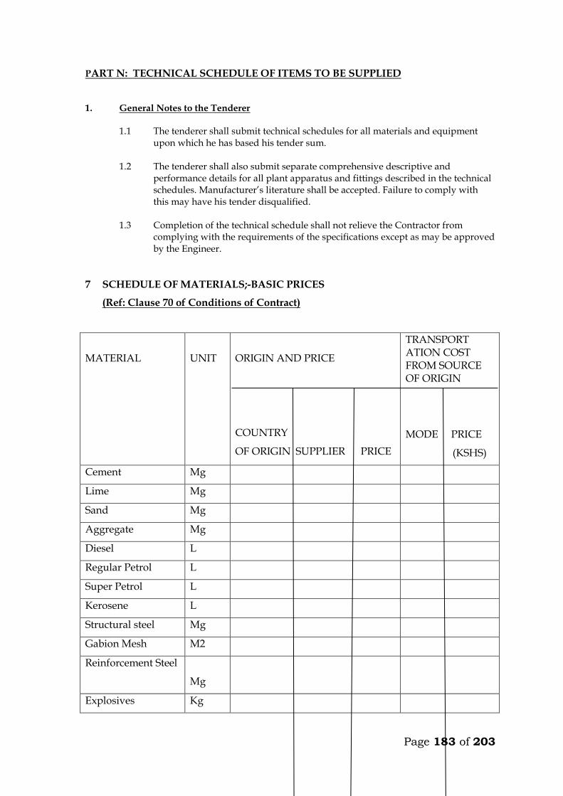
Page 183 of 203
PART N: TECHNICAL SCHEDULE OF ITEMS TO BE SUPPLIED 1. General Notes to the Tenderer
1.1 The tenderer shall submit technical schedules for all materials and equipment upon which he has based his tender sum.
1.2 The tenderer shall also submit separate comprehensive descriptive and
performance details for all plant apparatus and fittings described in the technical schedules. Manufacturer’s literature shall be accepted. Failure to comply with this may have his tender disqualified.
1.3 Completion of the technical schedule shall not relieve the Contractor from
complying with the requirements of the specifications except as may be approved by the Engineer.
7 SCHEDULE OF MATERIALS;-BASIC PRICES
(Ref: Clause 70 of Conditions of Contract)
MATERIAL
UNIT
ORIGIN AND PRICE
COUNTRY
OF ORIGIN SUPPLIER PRICE
TRANSPORT ATION COST FROM SOURCE OF ORIGIN
MODE PRICE
(KSHS)
Cement Mg
Lime Mg
Sand Mg
Aggregate Mg
Diesel L
Regular Petrol L
Super Petrol L
Kerosene L
Structural steel Mg
Gabion Mesh M2
Reinforcement Steel
Mg
Explosives Kg
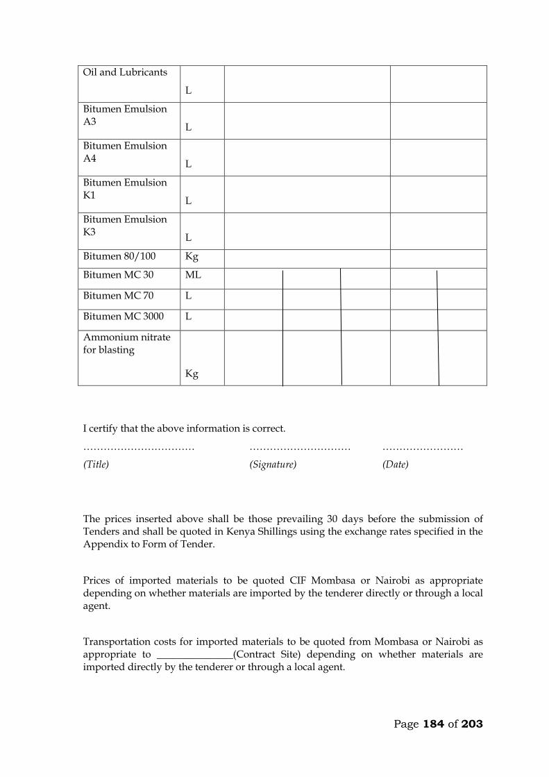
Page 184 of 203
Oil and Lubricants
L
Bitumen Emulsion A3
L
Bitumen Emulsion A4
L
Bitumen Emulsion K1
L
Bitumen Emulsion K3
L
Bitumen 80/100 Kg
Bitumen MC 30 ML
Bitumen MC 70 L
Bitumen MC 3000 L
Ammonium nitrate for blasting
Kg
I certify that the above information is correct.
…………………………… ………………………… ……………………
(Title) (Signature) (Date)
The prices inserted above shall be those prevailing 30 days before the submission of Tenders and shall be quoted in Kenya Shillings using the exchange rates specified in the Appendix to Form of Tender.
Prices of imported materials to be quoted CIF Mombasa or Nairobi as appropriate depending on whether materials are imported by the tenderer directly or through a local agent.
Transportation costs for imported materials to be quoted from Mombasa or Nairobi as appropriate to _______________(Contract Site) depending on whether materials are imported directly by the tenderer or through a local agent.
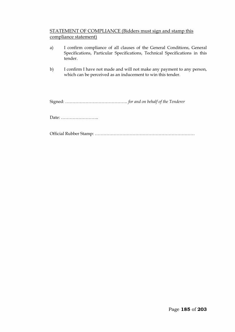
Page 185 of 203
STATEMENT OF COMPLIANCE (Bidders must sign and stamp this compliance statement)
a) I confirm compliance of all clauses of the General Conditions, General
Specifications, Particular Specifications, Technical Specifications in this tender.
b) I confirm I have not made and will not make any payment to any person,
which can be perceived as an inducement to win this tender. Signed: ……………………………………. for and on behalf of the Tenderer Date: …………………….. Official Rubber Stamp: ……………………………………………………………
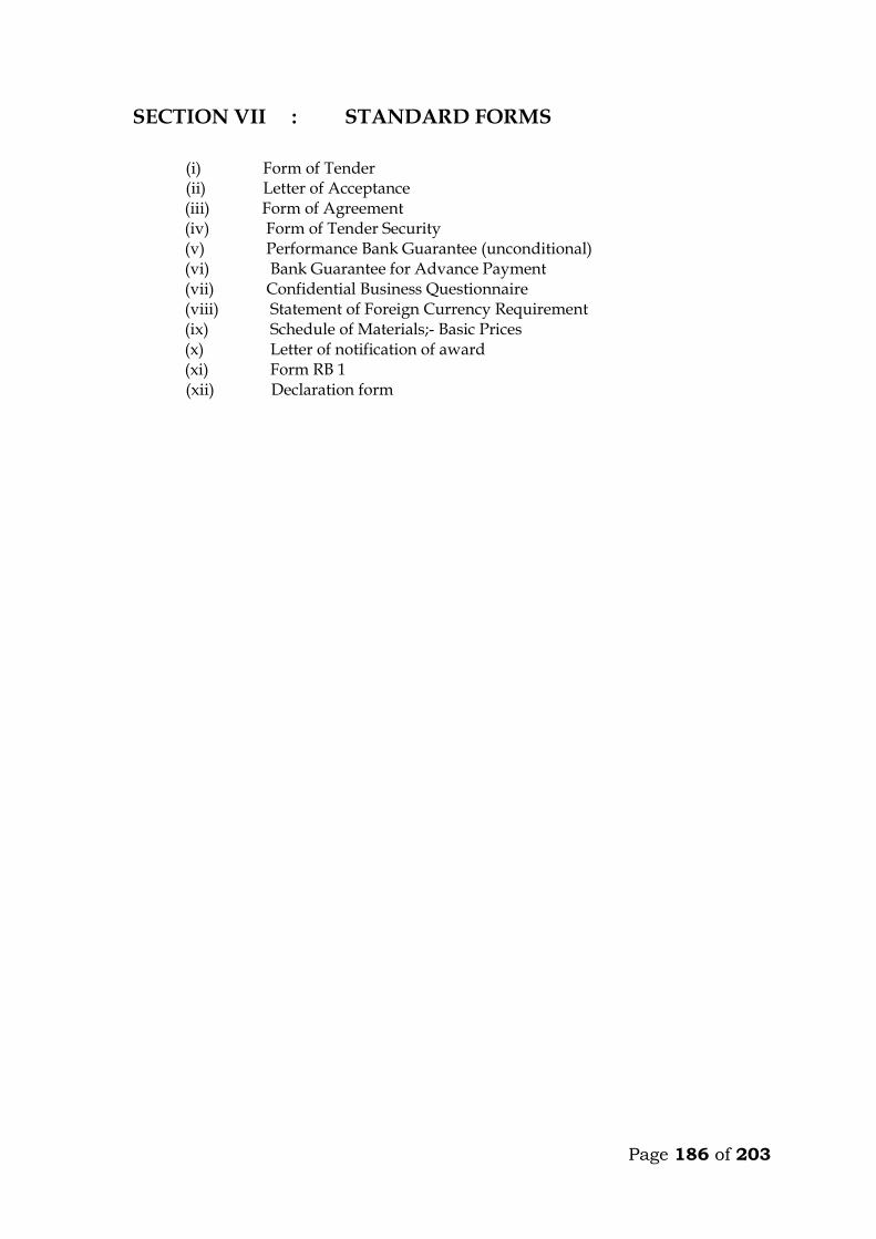
Page 186 of 203
SECTION VII : STANDARD FORMS
(i) Form of Tender
(ii) Letter of Acceptance (iii) Form of Agreement (iv) Form of Tender Security (v) Performance Bank Guarantee (unconditional) (vi) Bank Guarantee for Advance Payment (vii) Confidential Business Questionnaire (viii) Statement of Foreign Currency Requirement (ix) Schedule of Materials;- Basic Prices (x) Letter of notification of award (xi) Form RB 1 (xii) Declaration form

Page 187 of 203
7.1 FORM OF TENDER
TO: __________________________[Name of Employer) ____________[Date] __________________________[Name of Contract] Dear Sir, 1. In accordance with the Conditions of Contract, Specifications, Drawings and Bills
of Quantities for the execution of the above named Works, we, the undersigned offer to construct, install and complete such Works and remedy any defects therein for the sum of Kshs._____________________________[Amount in figures]Kenya Shillings___________________________________________________________________________________________[Amount in words]
2. We undertake, if our tender is accepted, to commence the Works as
soon as is reasonably possible after the receipt of the Project Manager’s notice to commence, and to complete the whole of the Works comprised in the Contract within the time stated in the Appendix to Conditions of Contract.
3. We agree to abide by this tender until ___________________[Insert date], and it shall
remain binding upon us and may be accepted at any time before that date. 4. Unless and until a formal Agreement is prepared and executed this tender together
with your written acceptance thereof, shall constitute a binding Contract between us. 5. We understand that you are not bound to accept the lowest or any tender you may
receive.
Dated this ____________________ day of _______20________________ Signature __________________in the capacity of___________________ duly authorized to sign tenders for and on behalf of _____________________________________________[Name of Employer] of___________________________________________[Address of Employer] Witness; Name______________________________________ Address_____________________________________ Signature___________________________________ Date_______________________________________

Page 188 of 203
7.2 FORM OF AGREEMENT
THIS AGREEMENT, made the _________________ day of ________ 20 ______ between ________________________________________________of [or whose registered office is situated at]__________________________________________ (hereinafter called “the Employer”) of the one part AND ________________________________________________________of[or whose registered office is situated at]_________________________________________ (hereinafter called “the Contractor”) of the other part. WHEREAS THE Employer is desirous that the Contractor executes ________________________________________________________________________ (name and identification number of Contract ) (hereinafter called “the Works”) located at______________________________[Place/location of the Works]and the Employer has accepted the tender submitted by the Contractor for the execution and completion of such Works and the remedying of any defects therein for the Contract Price of Kshs___________________________[Amount in figures],Kenya Shillings_____________________________________________[Amount in words]. NOW THIS AGREEMENT WITNESSETH as follows: 1. In this Agreement, words and expressions shall have the same meanings as are
respectively assigned to them in the Conditions of Contract hereinafter referred to.
2. The following documents shall be deemed to form and shall be read and
construed as part of this Agreement i.e.
(i) Letter of Acceptance
(ii) Form of Tender
(iii) Conditions of Contract Part I
(iv) Conditions of Contract Part II and Appendix to Conditions of Contract
(v) Specifications
(vi) Drawings
(vii) Priced Bills of Quantities 3. In consideration of the payments to be made by the Employer to the Contractor as
hereinafter mentioned, the Contractor hereby covenants with the Employer to execute and complete the Works and remedy any defects therein in conformity in all respects with the provisions of the Contract.
Page 189 of 203
4. The Employer hereby covenants to pay the Contractor in consideration of the execution and completion of the Works and the remedying of defects therein, the Contract Price or such other sum as may become payable under the provisions of the Contract at the times and in the manner prescribed by the Contract.
IN WITNESS whereof the parties thereto have caused this Agreement to be executed the day and year first before written. The common Seal of _________________________________________________ Was hereunto affixed in the presence of ________________________________ Signed Sealed, and Delivered by the said ______________________________ Binding Signature of Employer ________________________________________ Binding Signature of Contractor _______________________________________ In the presence of (i) Name_______________________________________ Address_____________________________________ Signature___________________________________
[ii] Name _______________________________________ Address_____________________________________ Signature____________________________________
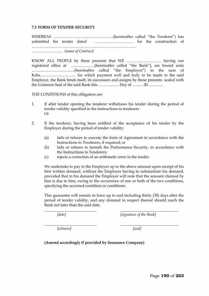
Page 190 of 203
7.3 FORM OF TENDER SECURITY WHEREAS ………………………………………..(hereinafter called “the Tenderer”) has submitted his tender dated ………………………… for the construction of ……………………………………………………………………… …………………… (name of Contract) KNOW ALL PEOPLE by these presents that WE ……………………… having our registered office at ………………(hereinafter called “the Bank”), are bound unto ……………………………(hereinafter called “the Employer”) in the sum of Kshs.……………………… for which payment well and truly to be made to the said Employer, the Bank binds itself, its successors and assigns by these presents sealed with the Common Seal of the said Bank this ……………. Day of ………20………… THE CONDITIONS of this obligation are: 1. If after tender opening the tenderer withdraws his tender during the period of
tender validity specified in the instructions to tenderers Or
2. If the tenderer, having been notified of the acceptance of his tender by the Employer during the period of tender validity:
(a) fails or refuses to execute the form of Agreement in accordance with the
Instructions to Tenderers, if required; or (b) fails or refuses to furnish the Performance Security, in accordance with
the Instructions to Tenderers; (c) rejects a correction of an arithmetic error in the tender.
We undertake to pay to the Employer up to the above amount upon receipt of his first written demand, without the Employer having to substantiate his demand, provided that in his demand the Employer will note that the amount claimed by him is due to him, owing to the occurrence of one or both of the two conditions, specifying the occurred condition or conditions. This guarantee will remain in force up to and including thirty (30) days after the period of tender validity, and any demand in respect thereof should reach the Bank not later than the said date.
___________________________ ______________________________ [date[ [signature of the Bank] ___________________________ ______________________________ [witness] [seal]
(Amend accordingly if provided by Insurance Company)

Page 191 of 203
7.4 PERFORMANCE BANK GUARANTEE (UNCONDITIONAL) To: _________________________(Name of Employer) ___________(Date) __________________________(Address of Employer) Dear Sir, WHEREAS ______________________(hereinafter called “the Contractor”) has undertaken, in pursuance of Contract No. _____________ dated _________ to execute _______________ (hereinafter called “the Works”); AND WHEREAS it has been stipulated by you in the said Contract that the Contractor shall furnish you with a Bank Guarantee by a recognised bank for the sum specified therein as security for compliance with his obligations in accordance with the Contract; AND WHEREAS we have agreed to give the Contractor such a Bank Guarantee: NOW THEREFORE we hereby affirm that we are the Guarantor and responsible to you, on behalf of the Contractor, up to a total of Kshs. ________________ (amount of Guarantee in figures) Kenya Shillings__________________________________________ (amount of Guarantee in words), and we undertake to pay you, upon your first written demand and without cavil or argument, any sum or sums within the limits of Kenya Shillings _________________________ (amount of Guarantee in words) as aforesaid without your needing to prove or to show grounds or reasons for your demand for the sum specified therein. We hereby waive the necessity of your demanding the said debt from the Contractor before presenting us with the demand. We further agree that no change, addition or other modification of the terms of the Contract or of the Works to be performed thereunder or of any of the Contract documents which may be made between you and the Contractor shall in any way release us from any liability under this Guarantee, and we hereby waive notice of any change, addition, or modification. This guarantee shall be valid until the date of issue of the Certificate of Completion.
SIGNATURE AND SEAL OF THE GUARANTOR ___________________ Name of Bank ____________________________________________
Address ________________________________________________
Date ______________________________________________________
(Amend accordingly if provided by Insurance Company)
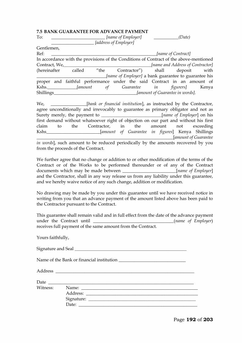
Page 192 of 203
7.5 BANK GUARANTEE FOR ADVANCE PAYMENT To: ________________________ [name of Employer] ___________(Date) ___________________ [address of Employer] Gentlemen, Ref: _______________________________________________[name of Contract] In accordance with the provisions of the Conditions of Contract of the above-mentioned Contract, We,_______________________________________[name and Address of Contractor] (hereinafter called “the Contractor”) shall deposit with _______________________________[name of Employer] a bank guarantee to guarantee his proper and faithful performance under the said Contract in an amount of Kshs._____________[amount of Guarantee in figurers] Kenya Shillings_____________________________________[amount of Guarantee in words]. We, ________________[bank or financial institution], as instructed by the Contractor, agree unconditionally and irrevocably to guarantee as primary obligator and not as Surety merely, the payment to ___________________________[name of Employer] on his first demand without whatsoever right of objection on our part and without his first claim to the Contractor, in the amount not exceeding Kshs________________________[amount of Guarantee in figures] Kenya Shillings _____________________________________________________________[amount of Guarantee in words], such amount to be reduced periodically by the amounts recovered by you from the proceeds of the Contract. We further agree that no change or addition to or other modification of the terms of the Contract or of the Works to be performed thereunder or of any of the Contract documents which may be made between ________________________[name of Employer] and the Contractor, shall in any way release us from any liability under this guarantee, and we hereby waive notice of any such change, addition or modification. No drawing may be made by you under this guarantee until we have received notice in writing from you that an advance payment of the amount listed above has been paid to the Contractor pursuant to the Contract. This guarantee shall remain valid and in full effect from the date of the advance payment under the Contract until ____________________________________(name of Employer) receives full payment of the same amount from the Contract. Yours faithfully, Signature and Seal __________________________________________________ Name of the Bank or financial institution ______________________________ Address ______________________________________________________________ Date _________________________________________________________________ Witness: Name: ____________________________________________________ Address: __________________________________________________ Signature: ________________________________________________ Date: _____________________________________________________

Page 193 of 203
7.6 CONFIDENTIAL BUSINESS QUESTIONNAIRE
You are requested to give the particulars indicated in Part 1 and either Part 2 (a), 2 (b) or 2 (c) and 2 (d) whichever applies to your type of business.
You are advised that it is a serious offence to give false information on this Form.
Part 1 – General
Business Name ………………………………………………………………………
Location of business premises; Country/Town……………………….
Plot No……………………………………… Street/Road …………………………
Postal Address……………………………… Tel No………………………………..
Nature of Business…………………………………………………………………..
Current Trade Licence No…………………… Expiring date…………………
Maximum value of business which you can handle at any time: K. pound………………………..
Name of your bankers………………………………………………………………
Branch…………………………………………………………………………………
Part 2 (a) – Sole Proprietor
Your name in full…………………………………… Age…………………………
Nationality………………………………… Country of Origin…………………
*Citizenship details …………………………………………………………………
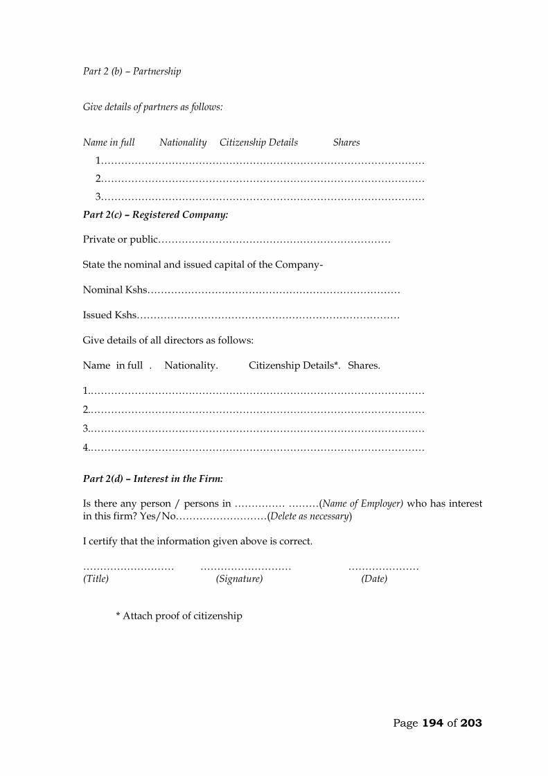
Page 194 of 203
Part 2 (b) – Partnership
Give details of partners as follows:
Name in full Nationality Citizenship Details Shares
1……………………………………………………………………………………
2……………………………………………………………………………………
3……………………………………………………………………………………
Part 2(c) – Registered Company:
Private or public……………………………………………………………
State the nominal and issued capital of the Company-
Nominal Kshs…………………………………………………………………
Issued Kshs……………………………………………………………………
Give details of all directors as follows:
Name in full . Nationality. Citizenship Details*. Shares.
1.………………………………………………………………………………………
2.………………………………………………………………………………………
3.………………………………………………………………………………………
4.………………………………………………………………………………………
Part 2(d) – Interest in the Firm:
Is there any person / persons in …………… ………(Name of Employer) who has interest in this firm? Yes/No………………………(Delete as necessary)
I certify that the information given above is correct.
……………………… ……………………… ………………… (Title) (Signature) (Date)
* Attach proof of citizenship
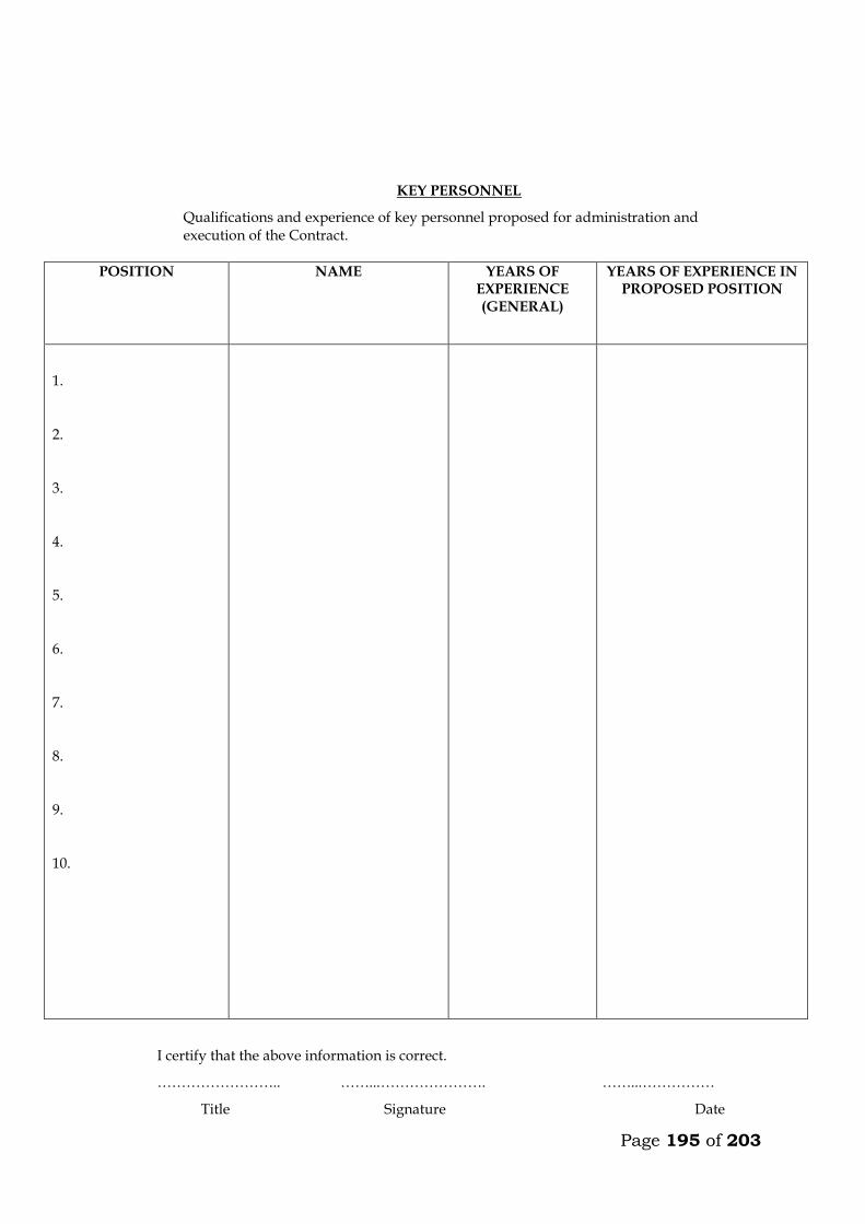
Page 195 of 203
KEY PERSONNEL
Qualifications and experience of key personnel proposed for administration and execution of the Contract.
POSITION NAME YEARS OF EXPERIENCE (GENERAL)
YEARS OF EXPERIENCE IN PROPOSED POSITION
1.
2.
3.
4.
5.
6.
7.
8.
9.
10.
I certify that the above information is correct.
…………………….. ……...…………………. ……...……………
Title Signature Date
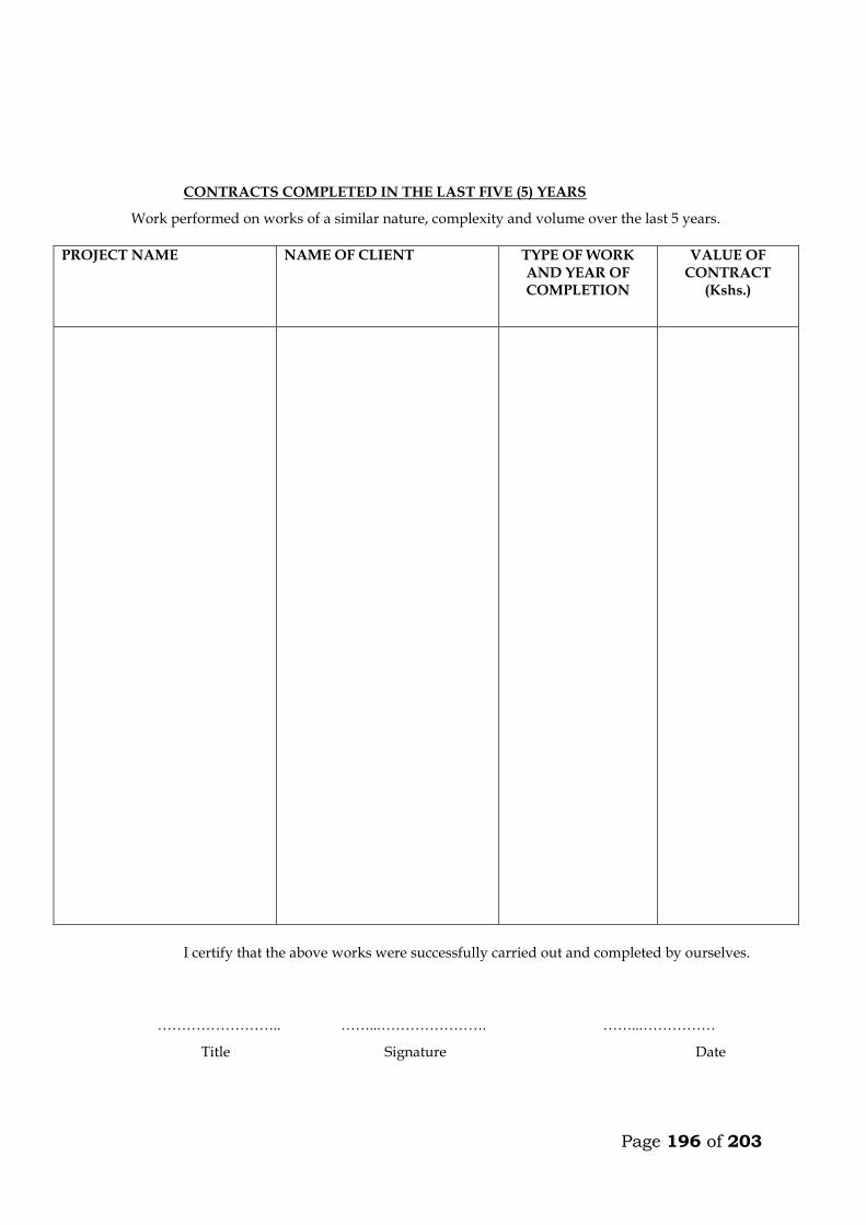
Page 196 of 203
CONTRACTS COMPLETED IN THE LAST FIVE (5) YEARS
Work performed on works of a similar nature, complexity and volume over the last 5 years.
PROJECT NAME NAME OF CLIENT TYPE OF WORK AND YEAR OF COMPLETION
VALUE OF CONTRACT
(Kshs.)
I certify that the above works were successfully carried out and completed by ourselves.
…………………….. ……...…………………. ……...……………
Title Signature Date
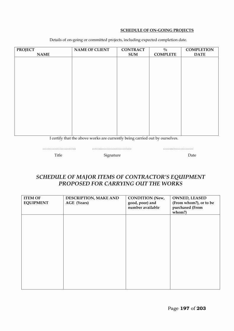
Page 197 of 203
SCHEDULE OF ON-GOING PROJECTS
Details of on-going or committed projects, including expected completion date.
PROJECT NAME
NAME OF CLIENT CONTRACT SUM
% COMPLETE
COMPLETION DATE
I certify that the above works are currently being carried out by ourselves.
…………………….. ……...…………………. ……...……………
Title Signature Date
SCHEDULE OF MAJOR ITEMS OF CONTRACTOR’S EQUIPMENT PROPOSED FOR CARRYING OUT THE WORKS
ITEM OF EQUIPMENT
DESCRIPTION, MAKE AND AGE (Years)
CONDITION (New, good, poor) and number available
OWNED, LEASED (From whom?), or to be purchased (From whom?)
Page 198 of 203
FINANCIAL REPORTS FOR THE LAST TWO YEARS
(Balance sheets, Profits and Loss Statements, Auditor’s reports, etc. List below and attach copies)
1. . . 2. . . 3. . .
EVIDENCE OF FINANCIAL RESOURCES TO MEET QUALIFICATION REQUIREMENTS (Cash in Hand, Lines of credit, e.t.c. List below and attach copies of supportive documents.)
1. . . 2. . . 3. . . 4. . . 5. . .
BIDDER’S BANK INFORMATION (This information is mandatory and should be for banks to provide reference if contacted by employer)
NAME OF BANK BANK BRANCH ACCOUNT
NAME ADDRESS TELEPHONE
Page 199 of 203
DETAILS OF LITIGATIONS OR ARBITRATION PROCEEDINGS IN WHICH THE TENDERER IS INVOLVED AS ONE OF THE PARTIES
1. . . 2. . . 3. . . 4. . . 5. . . 6. . . 7. . . 8. . . 9. . . 10 . .

Page 200 of 203
7.7 STATEMENT OF FOREIGN CURRENCY REQUIREMENTS
(See Clause 60[5] of the Conditions of Contract)
In the event of our Tender for the execution of____________________
__________________________(name of Contract) being accepted, we would require in accordance with Clause 21 of the Conditions of Contract, which is attached hereto, the following percentage:
(Figures)………………………… (Words)…………………………………
of the Contract Sum, (Less Fluctuations) to be paid in foreign currency.
Currency in which foreign exchange element is required:
………………………………………………………………………………………
Date: The ………… Day of …………….. 20…………….
Enter 0% (zero percent) if no payment will be made in foreign currency.
Maximum foreign currency requirement shall be _____________(percent) of the Contract Sum, less Fluctuations.
_____________________
(Signature of Tenderer)
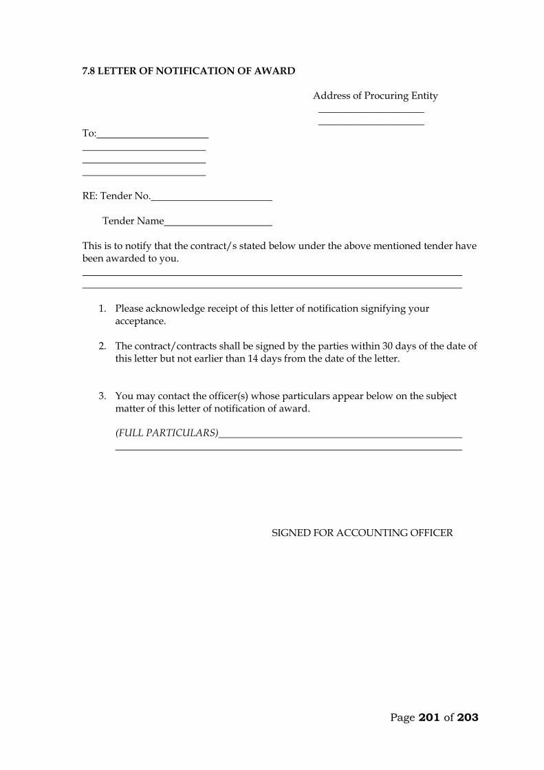
Page 201 of 203
7.8 LETTER OF NOTIFICATION OF AWARD
Address of Procuring Entity _____________________ _____________________ To: RE: Tender No. Tender Name This is to notify that the contract/s stated below under the above mentioned tender have been awarded to you.
1. Please acknowledge receipt of this letter of notification signifying your acceptance.
2. The contract/contracts shall be signed by the parties within 30 days of the date of
this letter but not earlier than 14 days from the date of the letter.
3. You may contact the officer(s) whose particulars appear below on the subject
matter of this letter of notification of award. (FULL PARTICULARS)
SIGNED FOR ACCOUNTING OFFICER
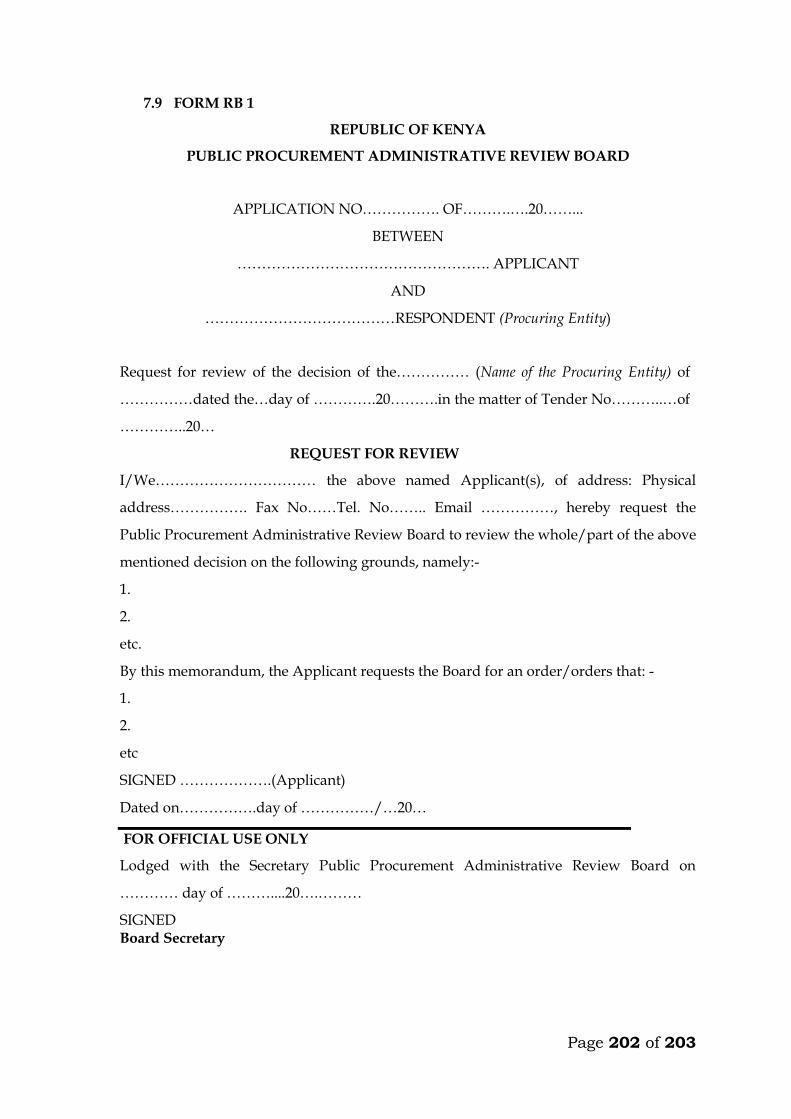
Page 202 of 203
7.9 FORM RB 1
REPUBLIC OF KENYA
PUBLIC PROCUREMENT ADMINISTRATIVE REVIEW BOARD
APPLICATION NO……………. OF……….….20……...
BETWEEN
……………………………………………. APPLICANT
AND
…………………………………RESPONDENT (Procuring Entity)
Request for review of the decision of the…………… (Name of the Procuring Entity) of
……………dated the…day of ………….20……….in the matter of Tender No………..…of
…………..20…
REQUEST FOR REVIEW
I/We…………………………… the above named Applicant(s), of address: Physical
address……………. Fax No……Tel. No…….. Email ……………, hereby request the
Public Procurement Administrative Review Board to review the whole/part of the above
mentioned decision on the following grounds, namely:-
1.
2.
etc.
By this memorandum, the Applicant requests the Board for an order/orders that: -
1.
2.
etc
SIGNED ……………….(Applicant)
Dated on…………….day of ……………/…20…
FOR OFFICIAL USE ONLY
Lodged with the Secretary Public Procurement Administrative Review Board on
………… day of ………....20….………
SIGNED Board Secretary
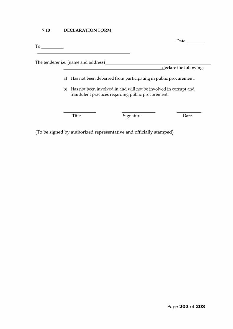
Page 203 of 203
7.10 DECLARATION FORM Date
To The tenderer i.e. (name and address)
declare the following: a) Has not been debarred from participating in public procurement. b) Has not been involved in and will not be involved in corrupt and
fraudulent practices regarding public procurement. Title Signature Date
(To be signed by authorized representative and officially stamped)