Embed Size (px)
Citation preview
Bandwidth-Optimal Complete Exchange onWormhole-Routed 2D/3D Torus Networks: ADiagonal-Propagation Approach xYu-Chee Tseng1, Ting-Hsien Lin2, Sandeep K. S. Gupta3, and Dhabaleswar K. Panda2AbstractAll-to-all personalized communication, or complete exchange, is at the heart of numerous ap-plications in parallel computing. Several complete exchange algorithms have been proposedin the literature for wormhole meshes. However, these algorithms, when applied to tori, cannot take advantage of wrap-around interconnections to implement complete exchange with re-duced latency. In this paper, a new diagonal-propagation approach is proposed to develop aset of complete exchange algorithms for 2D and 3D tori. This approach exploits the symmetricinterconnections of tori and allows to develop a communication schedule consisting of severalcontention-free phases. These algorithms are indirect in nature and they use message combiningto reduce the number of phases (message start-ups). It is shown that these algorithms e�ectivelyuse the bisection bandwidth of a torus which is twice that for an equal sized mesh, to achievecomplete exchange in time which is almost half of the best known complete exchange time onan equal sized mesh. The e�ectiveness of these algorithms are veri�ed through simulation stud-ies for varying system and technological parameters. It is also demonstrated that synchronousimplementations of these algorithms (by introducing barriers between phases) lead to reducedlatency for complete exchange with large messages, while the asynchronous ones are better forsmaller messages.Key Words: Collective communication, complete exchange, distributed memory systems, interprocessorcommunication, parallel computing, torus, wormhole routing.1 IntroductionThe mesh and torus networks have been recognized as powerful interconnection networks for mas-sively parallel computing. Mesh/torus-like low-dimensional networks have received a lot of attentionrecently for their better scalability to larger networks, as opposed to more complex networks suchas hypercubes [1]. Examples of machines with such topologies include the MasPar MP-1 [13], Intel1Department of Computer Science and Information Engineering, National Central University, Chung-Li, 32054,Taiwan, [[email protected]].2Department of Computer and Information Science, The Ohio State University, Columbus, OH 43210, U.S.A.,[ftlin,[email protected]].3Computer Science Department, Colorado State University, Ft. Collins, CO 80523 U.S.A.,[[email protected]]xA preliminary version of this paper appeared in Int'l Parallel Processing Symp., 1995 [22].1

Paragon, MIT J-Machine [5], Tera HORIZON [20], Cray T3D [4, 16], Polymorphic Torus [11],Fujitsu AP-1000, and iWarp [3].A torus is a mesh with wrap-around links. Although meshes and tori are generally regarded asclose families, there are still some distinctions: (i) As opposed to meshes, all nodes of a torus aretopologically symmetric, (ii) a torus has a smaller (about half) diameter compared to that of anequal-size mesh, and (iii) although the ratio of the number of links in a torus to that in a mesh isclose to one, the bisection bandwidthy of a torus is twice that of a mesh.The complete exchange (or all-to-all personalized communication or scatter) [14] is at the heartof numerous applications in parallel processing, such as matrix transposition, fast Fourier trans-form (FFT), distributed table-lookup, dynamic data re-distribution supported in High PerformanceFortran (HPF), etc. In this problem, each of the P processors in the network has an equal-size butdi�erent message to be delivered to each of the remaining P � 1 processors. Complete exchangealgorithms can be classi�ed into two categories: direct and indirect. In a direct algorithm (e.g.,[17, 18] for meshes), the complete exchange is performed in several contention-free phases. In eachphase, some of the messages are delivered directly from several source nodes to their respectivedestination nodes using disjoint paths. On the contrary, in an indirect solution (e.g., [2, 9, 19]for meshes), intermediate nodes may be used to bu�er, re-arrange, and forward the messages.In meshes, the indirect solutions tend to be more e�cient than the direct ones (see [9, 19] for acomparison).Complete exchange problem has been extensively studied for meshes [2, 9, 17, 18, 19]. However,these mesh algorithms when applied to tori may not be able to take advantage of wraparound linkse�ciently. This leads to the challenge of designing complete exchange algorithms for tori whichcan use the bisection bandwidth e�ectively.In this paper, we take on this challenge and consider the problem of complete exchange onboth 2D and 3D tori. We consider wormhole routed communication networks [6, 15], which arecharacterized by low communication latency and insensitivity to routing distance in the absenceof link contention. This switching technology has been used in many new-generation parallelmachines, such as the Intel Touchstone DELTA, Intel Paragon, and Cray T3D. For 2D tori, weconsider system con�gurations of size 2n � 2n for any positive integer n. For 3D tori, we considertwo di�erent con�gurations: 2n � 2n � 2n and (6� 2n)� (6� 2n)� (6� 2n).We propose a family of algorithms based on a new approach, called diagonal propagation, whichyBisection bandwidth is the minimum number of links across any hyperplane that cuts a network in half.2

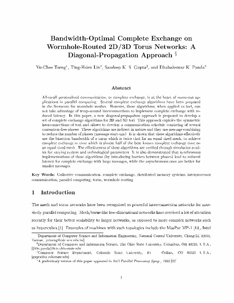
allows us to develop communication schedule with minimum number of contention-free phases whileutilizing maximum bisection bandwidth in every phase. These algorithms are based on the indirectmodel and only make minimal assumptions about the routers | a node only sends and receives atmost one message at a time (i.e. one-port model is used and a message only proceeds along a singledimension at a time. Single-port router architecture is common in current generation systems.Hence, the result can be immediately used by modern parallel machines. Recently, some completeexchange algorithms have been proposed for multidimensional tori. However, these either use adirect model [10, 21] or use a multi-port store-and-forward model [8].We compare, using simulations, the performance of our indirect complete exchange algorithmfor tori with the performance of the direct complete exchange algorithm for tori in [10]. As can beexpected, our indirect algorithm performs better than the direct algorithm when the messages areof reasonable length or the setup cost is high compared to the link transmission time. However, dueto the absence of any other known indirect complete exchange algorithm for tori, we compare theperformance of our schemes with the performance on tori of indirect complete exchange algorithmsdesigned for meshes [2, 9, 19]. Our algorithm only uses about half of the transmission time andhalf of the startup time, as opposed to the best-known mesh algorithm [9, 19]. Thus, with the samenetwork and system parameters (such as channel bandwidth and startup overhead, etc.), completeexchange can be done faster, by a factor of two, in a torus network than in a mesh network. Thisadvantage is due to the larger bisection bandwidth of a torus as compared to a mesh of same sizeand the capability of our algorithm to use this larger bisection bandwidth e�ectively. Simulationresults corresponding to varying system size, topology, message length, communication start-upoverhead, etc. testify to this advantage.The paper is organized as follows. Section 2 describes the wormhole-routed machine architectureconsidered in this paper. In Section 3 we present some design guidelines for our complete exchangealgorithms. In Section 4 we describe our scheme for 2D tori. The generalization of this algorithmto 3D tori is described in Section 5. We present the simulation results in Section 6. Finally,conclusions are drawn in Section 7.2 Complete Exchange on Wormhole-Routed TorusMulticomputers with direct networks supporting wormhole routing have become a popular trendin building large parallel systems. Most commonly used direct network topologies are meshes/tori.Figure 1 shows a two dimensional 4 � 4 torus system. Each node in the system comprises of a3
router and a processor. The routers are connected in a 4 � 4 con�guration with each link beinga bidirectional channel. Each processor is connected to its router through a set of injection andconsumption channels [15]. The injection (consumption) channels are used to inject (consume)messages to (from) the network. In this paper, we assume the one-port node architecture, i.e. eachnode is equipped with only one injection and one consumption channel. In our complete exchangealgorithms, a message proceeds only along one dimension at a time. Hence a torus using the populardimension-ordered routing is su�cient for implementing our algorithms.4x4 torus
processor
router
consumption channelinjection channel
memory
router interface
processor-memory bus
network links
Figure 1: A 4� 4 torus system with typical processor-router interface.In wormhole-routed networks, a packet is partitioned into a sequence of its, which are sentin a worm-like (or pipelined) manner. In the absence of contention, the communication latencyfor such networks is proportional to an additive factor of the message length and routing distance.In contrast to this, the communication latency in a store-and-forward network is proportional toa multiplicative factor of the message length and routing distance. Hence, wormhole routing isknown to be quite insensitive to routing distance in the absence of contention. For a message ofsize m bytes, the communication time can be modeled as ts+mtx, where ts is the message startuptime and tx is the time required to transmit a byte across a channel.zIn complete exchange, each of the P processors in the system has an equal-sized but di�erentmessages to be delivered to each of the remaining P�1 processors. In this paper, complete exchangeis achieved by a sequence of phases, where a phase consists of a subset of nodes communicatingin a contention-free manner. On parallel machines such as CM-5 [12] and Cray T3D [4, 16] whichprovide a dedicated networkx for barrier synchronization, these phases can be executed in a lock-zNote that this ignores the router overhead and routing distance. A more accurate formula would be ts + (m�1)(tsw+tx)+h(tnode+tx), where h is the number of links traversed by the header it and tnode (tsw) is the time takenby a router to process a header (non-header) it. In the simulator used to study the performance of our algorithm,this formula is used. However for simplicity, we use ts +mtx in our analytical model.xCM-5 calls the network as control network where synchronization and other operations are done, whereas CrayT3D only has a synchronization network. 4
step manner, one after another. However on machines which do not provide such mechanism,either phases could be separated by software barriers or they could be executed asynchronously.We have evaluated our scheme without barriers and with barriers of di�erent cost. These resultsare discussed in Section 6.We now develop some lower bounds for solving the complete exchange problem. In an N �Ntorus, there are 2N links crossing the bisection of the torus in each direction. The N22 nodes inone half of the bisection have (N22 )2 messages to be delivered to the other half. Thus, a lowerbound on the transmission time (i.e. communication time not including the startup time) would beN44�2N tx(= N38 tx) no matter whether a direct or an indirect solution is used. However, at least N38 tsstartup time is required with a direct model because a message can not be bu�ered at intermediatenodes. The direct solution in [21] does achieve both these startup and transmission lower bounds.Usually, the startup time is about an order (sometimes more) of magnitude larger than the messagepropagation time [7]. Hence it is desirable to develop complete exchange algorithms which canreduce the number of message startups. Our algorithm uses message combining and bu�ering inthe intermediate nodes to reduce the number of startups by an order of magnitude. Such completeexchange algorithms are known as indirect algorithms {. In this paper, we present a family ofindirect solutions which signi�cantly reduces the startup time to � N2 ts for both N � N andN � N � N torus. However, this is achieved by a small increase in transmission time. We nextsummarize the lower bound on the transmission time for future references.Lemma 1 On a k-dimensional torus with each dimension of size N , a lower bound on the to-tal message transmission time for performing the complete exchange of messages of size m ismaxfNk+1mtx8 ; (Nk � 1)mtxg. A lower bound on the message startup time is (log2Nk)ts.Proof: There are 2Nk�1 links crossing the bisection. The Nk2 processors in one half of the torushave (Nk2 )2 messages for processors in the other half. Hence, the transmission time has a lowerbound of ((N2km4 )�2Nk�1)tx = Nk+1mtx8 : The other lower bound in due to the one-port assumption.The bound for startup time is from the necessity for one node to distribute its messages to the restof the network. 2A complete exchange algorithm is called �-bandwidth-optimal if its transmission time is withina constant, �, factor of the optimal transmission time. Note that a �-bandwidth-optimal complete-exchange algorithm on a mesh would be 2�-bandwidth-optimal on an equal-size torus.{Indirect complete exchange algorithms are those which require less than P � 1 startups on a system of size P .5
Table 1: Comparison of indirect complete exchange algorithms for 2D N �N meshes/tori.Algorithm � on mesh � on torus startup timeNtsBinary Exchange [2] 6 12 3/2Binary-Interleaved Exchange [9] 2 4 1Cyclic Exchange [19] 2 4 1Diagonal Propagation N/A 2 1/2Table 1 summarizes the relative transmission costs (in terms of �) and startup costs of ourDiagonal Propagation scheme and some indirect complete exchange algorithms which were primarilydesigned for meshes. The comparison is made for only 2D N �N systems, since most of the meshalgorithms have been proposed for only 2D systems. It can be observed that diagonal propagationscheme is more bandwidth-optimal compared to other schemes.3 Diagonal Propagation Algorithms: An OverviewIn this section, we give an overview of our complete exchange algorithms. We �rst highlight somedesign guidelines through an example on a 1D ring. We then extend these ideas to a 2D, 2n � 2n ,torus. A straightforward extension of this algorithm to a 3D torus is then discussed. However, thisrequires the 3D torus to be of size (6 � 2n) � (6 � 2n) � (6 � 2n). We then show how these ideascan be extended to a 2n � 2n � 2n torus. Detailed algorithms for 2D and 3D tori are presented inSection 4 and Section 5, respectively.3.1 Message Propagation in 1D ToriFig. 2(a) illustrates how complete exchange can be performed on a ring of eight nodes. We ignorethe issue of communication contention for the time being. Each node uses the well-known recursive-doubling technique and distributes its messages in three steps. In the �rst step, each node x sendsits messages for nodes x+4; x+5; x+6, and x+7 to node x+4 (here we use modulo-8 arithmetics).In the second step, each node x sends its messages as well as those received in step one for nodesx+ 2 and x+ 3 to node x+ 2. Finally, each node x sends its message as well as those received inprevious two steps for node x+ 1 to node x+ 1.Ignoring the stride distance for the time being, let us concentrate on the direction of the messagepropagation. We can denote the three message propagation steps in Fig. 2(a) as H+H+H+, where Hstands for \horizontal", and + for \positive direction." One can easily develop an alternative schemeH�H�H�, where � stands for \negative direction", by reversing the communication direction inFig. 2(a). In fact, we can also mix H+ and H� together to get a H�H�H+ as shown in Fig. 2(b).6

0 1 2 3 4 5 6 7 0 1 2 3
0 1 2 3 4 5 6 7 0 1
0 1 2 3 4 5 6 7 0
H+
H+
H+
0 1 2 3 4 5 6 7 0 1 2 3
0 1 2 3 4 5 6 7 0 1
0 1 2 3 4 5 6 7 0
H-
H-
H+
(a) H+ H+ H+ (b) H- H- H+Figure 2: Two possible ways to achieve complete exchange in a 1D torus.In the �rst H�, each x sends its messages for x� 3; x� 4; x� 5; and x� 6 to x� 4. In the secondH�, each x sends messages for x� 1 and x� 2 to x� 2. Finally, an H+ completes the job.One issue in the above scheme is to determine which messages should be sent in which steps.In our algorithm, each node will keep an array of messages. The way that messages are arrangedin the array will depend on how messages are propagated. Sometimes we even need a messagerearrangement step to \unify" two message arrays that result from di�erent ways of propagation.This is an issue which will be further pursued in Section 4.3.2 Extension to 2D ToriIn a 2n � 2n torus, we have two more message propagations, V+ and V�, where V stands for\vertical." A naive extension to achieve complete exchange on a 2D torus is to alternately use H+and V+ as follows: an H+ with a stride distance of 2n�1, followed by a V+ with a stride distance of2n�1, followed by an H+ with a stride distance of 2n�2, followed by a V+ with a stride distance of2n�2, . . . , followed by an H+ with a stride distance of 1, and �nally, a V+ with a stride distance of1. Fig. 3(a) depicts the �rst two steps. As one can see, several messages simultaneously try to usethe same links resulting in severe link contention. On wormhole routed systems, link contentionshould be avoided to retain the advantages of wormhole routing.In the above example, links in directions H� and V� are not used. To alleviate the contention,we can divide nodes into four groups in such a manner that nodes in column i and i + 4(mod 8)are in the same group. Each group will use only one direction of links (H�, H+, V�, or V+) at atime. Therefore, the steps in Fig. 3(a) can be transformed into equivalent ones in Fig. 3(b). Nowcommunications for groups 0 and 2 are contention-free, but contention still exists for groups 1 and3 due to nodes located at the same column performing V+ or V�.To completely eliminate the link contention, we introduce grouping along the main diagonal or7

(a) (b)contention contention
contention in each row contention in each column
group 0 nodes
group 1 nodes
group 2 nodes
group 3 nodesFigure 3: Complete exchange on 2D torus with (a) a naive extension and (b) naive extension with grouping.These steps are not contention-free. Messages over some wrap-around links are not shown for clarity.the main diagonal after shifting horizontally or vertically. Observe that no two nodes in a diagonalare located in the same row/column. Fig. 4(a) shows the grouping for an 8 � 8 torus; the formalde�nition is delayed till Section 4. In phase 1, nodes in group G0 communicate with other nodes inthe same group using links in the H+ direction, while nodes in groups G1, G2, and G3 respectivelyuse links in V+, H�, and V� directions. In phase 2, nodes in groups G0, G1, G2, and G3 use V+,H�, V�, and H+, respectively. It is not di�cult to see that these two phases are equivalent tothose in Fig. 3(a). Furthermore, each phase is contention-free. Fig. 4(b) and (c) illustrates the twocommunication phases and the \orientations" of these communications.phase 1
phase 2
2
1
2
1
2 2(2) (2)
(1)
(2)
(1)
(2)
(a) (c)
1
2 21
2
2
(1)
(2) (2)(1)
(2)
(2)
(b)
G0 nodes
G1 nodes
G2 nodes
G3 nodes
(H+)
(V+)
(V+)
(H-)
(H-)
(V-)
(V-)
(H+)
G0
G1
G2
G3
G0 G1
G2
G3
Figure 4: Diagonal message exchange: (a) one iteration in an 8 � 8 torus, (b) tra�c pattern in general,and (c) orientation of communication in di�erent groups. The numbers over an arrow indicates the step inwhich the communication corresponding to that arrow is performed.We compare the message propagation steps in the naive solution and our diagonal scheme in8
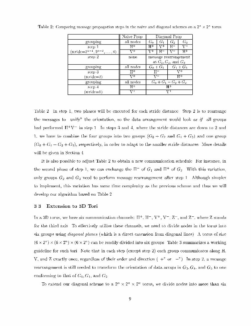
Table 2: Comparing message propagation steps in the naive and diagonal schemes on a 2n � 2n torus.Naive Prop. Diagonal Prop.grouping all nodes G0 G1 G2 G3step 1 H+ H+ V+ H� V�(stride=2n�1; 2n�2; : : : ; 4) V+ V+ H� V� H+step 2 none message rearrangementat G1; G2; and G3grouping all nodes G0 +G2 G1 +G3step 3 H+ H+ V+(stride=2) V+ V+ H+grouping all nodes G0 +G1 +G2 +G3step 4 H+ H+(stride=1) V+ V+Table 2. In step 1, two phases will be executed for each stride distance. Step 2 is to rearrangethe messages to \unify" the orientation, so the data arrangement would look as if all groupshad performed H+V+ in step 1. In steps 3 and 4, where the stride distances are down to 2 and1, we have to combine the four groups into two groups (G0 + G2 and G1 + G3) and one group(G0 +G1 +G2 +G3), respectively, in order to adapt to the smaller stride distances. More detailswill be given in Section 4.It is also possible to adjust Table 2 to obtain a new communication schedule. For instance, inthe second phase of step 1, we can exchange the H� of G1 and H+ of G3. With this variation,only groups G2 and G3 need to perform message rearrangement after step 1. Although simplerto implement, this variation has same time complexity as the previous scheme and thus we willdevelop our algorithm based on Table 2.3.3 Extension to 3D ToriIn a 3D torus, we have six communication channels: H+, H�, V+, V�, Z+, and Z�, where Z standsfor the third axis. To e�ectively utilize these channels, we need to divide nodes in the torus intosix groups using diagonal planes (which is a direct extension from diagonal lines). A torus of size(6� 2n)� (6� 2n)� (6� 2n) can be readily divided into six groups. Table 3 summarizes a workingguideline for such tori. Note that in each step (except step 2) each group communicates along H,V, and Z exactly once, regardless of their order and direction (\+" or \�"). In step 2, a messagerearrangement is still needed to transform the orientation of data arrays in G3; G4, and G5 to oneconforming to that of G0; G1, and G2.To extend our diagonal scheme to a 2n � 2n � 2n torus, we divide nodes into more than six9

Table 3: Diagonal propagation directions in a 3D N 0 �N 0 �N 0 torus, where N 0 = 6� 2n.grouping G0 G1 G2 G3 G4 G5step 1 H+ V+ Z+ H� V� Z�(stride=6 � 2n�1; 6 � 2n�2; : : : ; 6) Z+ H+ V+ Z� H� V�V+ Z+ H+ V� Z� H�step 2 message rearrangementat G3; G4, and G5grouping G0 +G3 G1 +G4 G2 +G5step 3 H+ V+ Z+(stride = 3) Z+ H+ V+V+ Z+ H+grouping G0 +G1 +G2 +G3 +G4 +G5step 4 H+(stride = 1) V+Z+step5 H+(stride = 1) V+Z+groups, so as to fully utilize links along all directions. A natural choice is eight groups. But sinceat most six groups can be active at any given time (there are three dimensions, each with a positiveand a negative direction) without causing contention, the remaining two groups must stay idle,communication-wise. Thus the problem of message propagation in 2n � 2n � 2n tori reduces to asimple arrangement problem as follows:Problem: How to place 24 symbols (8 sets of H�, V�, and Z�, where � = +=�) into an array of8 columns and minimal rows such that (i) each column has exactly one H, V, and Z, (ii) in eachrow each of H+, H�, V+, V�, Z+, and Z� appears at most once.One solution to this problem is shown in step 1 of Table 4. In addition to meeting the aboverequirements, it has another merit: the even-numbered groups have performed H+V+Z+, and theodd-numbered groups H�V�Z�. Therefore, only odd-numbered groups need to perform the datarearrangement step, and the rearrangement rule is the same for all of them.4 Diagonal Propagation Scheme for 2D ToriIn this section, we describe our complete exchange algorithm for a 2D N �N;N = 2n; torus.4.1 De�nitionsWe begin with de�nitions of node groupings, array slicing operators, and communication operatorswhich are later used to describe our complete exchange algorithm.10

Table 4: Diagonal propagation directions in a 3D N �N �N torus, where N = 2n.grouping G0 G1 G2 G3 G4 G5 G6 G7step 1 H+ V� Z+ H� V+ Z� idle idle(stride= 2n�1; 2n�2; : : : ; 8) idle idle H+ V� Z+ H� V+ Z�V+ Z� idle idle H+ V� Z+ H�Z+ H� V+ Z� idle idle H+ V�grouping G0 +G4 G1 +G5 G2 +G6 G3 +G7step 2 H+ H� V+ V�(stride = 4) V+ V� Z+ Z�Z+ Z� H+ H�step 3 message rearrangementat G1; G3; G5, and G7grouping G0 +G2 +G4 +G6 G1 +G3 +G5 +G7step 4 H+ V+(stride = 2) V+ Z+Z+ H+grouping G0 +G1 +G2 +G3 +G4 +G5 +G6step 5 H+(stride = 1) V+Z+4.1.1 Node GroupingThe nodes of a 2D torus are denoted as Pi;j, where 0 � i; j < N . A node Pi;j is connected toPi�1;j ; Pi+1;j ; Pi;j�1; and Pi;j+1. Throughout this paper, all indices are modulo-N numbers (i.e.,i = i0 i� i mod N = i0 mod N). The torus is viewed as being placed on an xy-plane with the �rstand the second indices increasing along with the positive x- and y-axes, respectively. These nodesare divided into four groups, namely G(2)k , k = 0::3 (the superscript (2) stands for \2D"). A nodePi;j 2 G(2)k i� (i� j) mod 4 = k. See Fig. 4(a) for an example.We de�ne the i-th horizontal-wise diagonal H(2)i ; i = 0; 1; :::; N � 1; to be a sequence of nodessuch that H(2)i = (Pi;0; Pi+1;1; Pi+2;2; : : : ; Pi+N�1;N�1); (1)and similarly the i-th vertical-wise diagonal of 2D torus V (2)i to beV (2)i = (P0;�i; P1;1�i; P2;2�i; : : : ; PN�1;N�1�i): (2)Note that H(2)i and V (2)i have the same nodes, which are ordered di�erently in each sequence. Alsonote that for any k, where 0 � k � 3, all nodes of H(2)i and V (2)i , such that i mod 4 = k, belongto the same group G(2)k . The j-th elements of H(2)i and V (2)i will be denoted as H(2)i [j] and V (2)i [j],respectively. 11
4.1.2 Array Slicing OperatorsIn the complete exchange problem, each node in the torus has a message to be delivered to each ofthe remaining N2�1 nodes. Without loss of generality, we assume that each Pi;j has N2 messages,including one dummy message for itself. These messages are stored in an array Mi;j[0 : N � 1; 0 :N � 1], one message per location. One of the main issues in this paper is concerned with the useof these arrays.Given an array M [0 : N � 1; 0 : N � 1] and an integer � that divides N , we de�ne the h(2)� -slicing (read as 2D horizontal-wise step-� slicing) of M to be the partition of M into N� sub-arrays,M [i� : (i+1)�� 1; 0 : N � 1], where i = 0::N� � 1. (Note that visually the array is sliced vertically.)Sub-array M [i� : (i+ 1)� � 1; 0 : N � 1] is called the i-th block of such slicing. Similarly, we de�nethe v(2)� -slicing (2D vertical-wise step-� slicing) of M as the blocks M [0 : N � 1; i� : (i+ 1)� � 1].4.1.3 Communication OperatorsLet P and P 0 be two nodes di�ering in either x or y component. Then, sending a message from Pto P 0 along that dimension is denoted as a path P d! P 0, where d 2 f+;�g. If d =\+" (\�"), therouting will proceed in the positive (negative) direction of that dimension. We further generalizethis notation and de�ne a set of paths between two horizontal-wise diagonals:H(2)i d! H(2)j = fH(2)i [m] d! H(2)j [m] j m = 0::N � 1g: (3)The notation V (2)i d! V (2)j is similarly de�ned. Next we de�ne two communication operators, Hand V, corresponding to the notations, H� and V�, as introduced in Section 3.De�nition 1 Let m be any integer, � be any integer that divides N , and d 2 f+;�g. De�neH(2)(m; �; d) = N=��1[i=0 H(2)m+i� d! H(2)m+(i+1)� : (4)(Intuitively, m is some o�set, � means a stride distance, and d indicates some direction.) Foreach path Px;y d! Px+�;y in H(m; �; d), node Px;y performs a h(2)� -slicing on Mx;y and sends allentries Mx;y[a; b] located in odd-numbered slices to Px+�;y, which then stores them in locationMx+�;y[a� 2�; b].k Similarly, we de�neV(2)(m; �; d) = N=��1[i=0 V (2)m+i� d! V (2)m+(i+1)� ; (5)kIn other words, perform the h(2)� -slicing on Mx;y and Mx+�;y. Each k-th slice of Mx;y, such that k is odd, isassigned to the k0-th slice of Mx+�;y, where k0 = (k � 2) mod N� .12

with the exception that in each Px;y d! Px;y+�, a v(2)� -slicing is performed.Fig. 5(a) shows the message exchange before and after executing a communication Px;y d! Px+�;ybelonging to a H(2)(m; �; d) operation, where � = N4 . Each slice is of size N4 � N . Note that thevalues of slices marked by � will be determined by the array Mx��;y owned by node Px��;y. Simi-larly, Fig. 5(b) is for Px;y d! Px;y+� belonging to a V(2)(m; �; d) operation. As another example, inthe phase 1 of Fig. 6, all black round nodes are performing a H(2)(0; 4;+) in an 8� 8 torus, whileall white round nodes are performing a V(2)(1; 4;+) operation.a3
a2a1a0
Mx,y Mx+δ,y
before after
(b)
a0 a1 a2 a3
Mx,y
b0 b1 b2 b3
Mx+δ,y
before
a0 * a2 *
Mx,y
b0 a3 b2 a1
Mx+δ,y
after
(a)
b3
b2b1b0
*a2
*a0
Mx,yMx+δ,y
a1
b2a3b0Figure 5: Examples of (a) the H(2)(m; �; d) operation and (b) the V(2)(m; �; d) operation.Below we give an example of using the above operators. It also shows conceptually how completeexchange can be done.Example 1 Suppose each node Pi;j keeps an array Mi;j[0 : N�1; 0 : N�1], where Mi;j[x; y] storesthe message for Pi+x;j+y, x; y = 0::N � 1. Using the operator H (with appropriate parameters),Pi;j can send the sub-array Mi;j[N=2 : N � 1; 0 : N � 1] to Pi+N=2;j . Then using operator V, Pi;jand Pi+N=2;j may concurrently send sub-arrays Mi;j [0 : N=2 � 1; N=2 : N � 1] and Mi;j[N=2 :N � 1; N=2 : N � 1] to Pi;j+N=2 and Pi+N=2;j+N=2, respectively. After these, we can regard the torusas being partitioned into four quadrants, and each of Pi;j, Pi+N=2;j, Pi;j+N=2, and Pi+N=2;j+N=2 asa source node in one of the quadrants to help distributing Pi;j's messages recursively.4.2 The Algorithm: Diagonal Propagation 2DRecall that each Pi;j will keep an array Mi;j of messages. Initially, the message in Mi;j [a; b] isdestined for a node denoted as dest(Mi;j[a; b]) (note that dest() is not a function on Mi;j [a; b]). Wede�ne dest(Mi;j [a; b]) = 8>>>><>>>>: Pi+a;j+b if Pi;j 2 G(2)0Pi+3�a;j+b if Pi;j 2 G(2)1Pi+3�a;j+3�b if Pi;j 2 G(2)2Pi+a;j+3�b if Pi;j 2 G(2)3 : (6)Nodes in di�erent groups follow di�erent rules of message arrangement. The arrangement is tofacilitate using our communication operators. 13

As outlined in Table 2, the routing algorithm Diagonal Propagation 2D() consists of four steps.In step 1, nodes communicate with other nodes that are �k = 2k hops away, where k = n� 1; n�2; :::; 2. Step 2 performs some data rearrangement. Steps 3 and 4 are in fact special cases of step 1,except that nodes communicate with other nodes that are �1 and �0 hops away, respectively. Step1 of this algorithm can be formally presented as follows:Step 1: /� stride distance = �k, k = n� 1; n� 2; :::; 2. �/for k = n� 1 downto 2 dofor m = 0 to �k � 1 step 4 doPerform the following two phases:(i) the union of H(2)(m; �k;+);V(2)(m+ 1;��k;+);H(2)(m+ 2;��k;�), and V(2)(m+ 3; �k;�),(ii) the union of V(2)(m;��k;+);H(2)(m+ 1;��k;�);V(2)(m+ 2; �k;�), and H(2)(m+ 3; �k;+);end for;end for;This step implements the step 1 in Table 2. The loop index k controls the stride distance ofcommunications. For each value of k, there are �k2 phases, and each node will be scheduled to sendand receive two messages in two of these phases. In this step, a node always communicates withother nodes in the same group to which the node also belongs. Depending on a node's group mem-bership, we have the following four cases. A node in G(2)0 will send and receive one message due totheH(2)(m; �k;+) operation in (i), and will send and receive another message due to V(2)(m;��k;+)operation in (ii). Similarly, a node in G(2)1 will send (receive) one message due to V(2)(m+1;��k;+)operation in (i) and another due to H(2)(m + 1;��k;�) operation in (ii); etc. For instance, in an8� 8 torus, Fig. 6 shows the phase 1 (H(2)(0; 4;+);V(2)(1;�4;+);H(2)(2;�4;�);V(2)(3; 4;�)) andphase 2 (V(2)(0;�4;+);H(2)(1;�4;�); V(2)(2; 4;�);H(2)(3; 4;+)) produced by this step. Note thatfor simplicity only typical paths are shown; in each �gure, every node of the same pattern will havea path leading to another node of the same relative position. Assuming � = N4 , Fig. 7 shows thechange of memory state after one iteration for a node in G(2)0 .As the value of Mi;j will change after the execution of each phase, let's denote M<k>i;j as thestate of Mi;j after executing the outer for-loop with index k = n � 1; n � 2; :::; 2. The initialvalue of Mi;j is denoted by M<n>i;j . Intuitively, the e�ect is that for any Pi;j 2 G(2)0 and any0 � x; y < N=�k, the sub-array M<k>i;j [x�k : (x+1)�k � 1; y�k : (y+1)�k � 1] contains the messagesfrom Pi+x�k;j+y�k destined for the set of nodes fPi+r;j+s j 0 � r; s < �kg. For any Pi;j 2 G(2)1 , thesub-array M<k>i;j [x�k : (x + 1)�k � 1; y�k : (y + 1)�k � 1] contains the messages from Pi�x�k;j+y�k14

phase 1
phase 2
phase 3 phase 5
phase 4 phase 6Figure 6: Routing example in an 8 � 8 torus. Phases 1 and 2 are produced by step 1; phases 3 and 4 bystep 3; and phases 5 and 6 by step 4. (For clarity, only representative communication patterns in each phaseare shown.)Mx-δ,y
Mx-δ,y-δ
Mx,y
Mx,y-δ
b03 b13 b23 b33
b02 b12 b22 b32
b01 b11 b21 b31
b00 b10 b20 b30
a03 a13 a23 a33
a02 a12 a22 a32
a01 a11 a21 a31
a00 a10 a20 a30
d03 d13 d23 d33
d02 d12 d22 d32
d01 d11 d21 d31
d00 d10 d20 d30
c03 c13 c23 c33
c02 c12 c22 c32
c01 c11 c21 c31
c00 c10 c20 c30
Mx-δ,y
Mx-δ,y-δ
Mx,y
Mx,y-δ
b03 * b23
b02 b22
b01 b21
b00 b20
a03 b33 a23 b13
a02 b32 a22 b12
a01 b31 a21 b11
a00 b30 a20 b10
d03 d23
d02 d22
d01 d21
d00 d20
c03 d33 c23 d13
c02 d32 c22 d12
c01 d31 c21 d11
c00 d30 c20 d10
*
*
*
*
*
*
*
*
*
*
*
*
*
*
*
Mx-δ,y
Mx-δ,y-δ
Mx,y
Mx,y-δ
d01 * d21
b02 b22
d03 d23
b00 b20
c01 d31 c21 d11
a02 b32 a22 b12
c03 d33 c23 d13
a00 b30 a20 b10
d02 d22
d00 d20
c02 d32 c22 d12
c00 d30 c20 d10
*
*
*
*
*
*
*
*
*
*
*
*
*
*
*
* * * ** *
* * * * * *
(a) (b) (c)Figure 7: (a) The original memory state of a node 2 G(2)0 before an iteration, (b) the state after executingH(2)(m; �;+), and (c) the state after executing V(2)(m;��;+).15

destined for fPi+3�r;j+sj0 � r; s < �kg. Similar statements can be established for nodes in G(2)2 andG(2)3 groups. This result is precisely described by the following lemma.Lemma 2 Consider any M<k>i;j [a; b], where k = 2::n. If a = u + x�k and b = v + y�k, whereu; v; x; y are unique integers such that 0 � u; v < �k and 0 � x; y < N�k , thenM<k>i;j [a; b] = 8>>>>><>>>>>: M<n>i+x�k;j+y�k [u� x�k; v � y�k] if Pi+x�k ;j+y�k 2 G(2)0M<n>i�x�k;j+y�k [u� x�k; v � y�k] if Pi�x�k ;j+y�k 2 G(2)1M<n>i�x�k;j�y�k [u� x�k; v � y�k] if Pi�x�k ;j�y�k 2 G(2)2M<n>i+x�k;j�y�k [u� x�k; v � y�k] if Pi+x�k ;j�y�k 2 G(2)3 : (7)Proof. We only prove the case of Pi+x�k;j+y�k 2 G(2)0 by induction on k. The proof of other caseswould be similar. When k = n, Eq. (7) is clearly true. Suppose Eq. (7) is true for some k. Letu = u0+x0�k�1 and v = v0+y0�k�1, where 0 � u0; v0 < �k�1 and 0 � x0; y0 � 1 (note that u0; v0; x0; y0must be unique). Then a = u + x�k = u0 + (x0 + 2x)�k�1 and b = v + y�k = v0 + (y0 + 2y)�k�1.As Pi;j 2 G(2)0 , it will execute two operations: H(2)(m; �k�1;+) and V(2)(m;��k�1;+) in iterationk � 1. Consider the possible values of x0 and y0.(i) If x0 = y0 = 0, then M<k>i;j [a; b] is unchanged (refer to the blocks a00; a02; a20 and a22 inFig. 7(c)), so M<k�1>i;j [a; b]= M<k>i;j [a; b]= M<n>i+x�k;j+y�k [u� x�k; v � y�k]= M<n>i+(x0+2x)�k�1;j+(y0+2y)�k�1 [u0 � (x0 + 2x)�k�1; v0 � (y0 + 2y)�k�1]and Eq. (7) is proved.(ii) If x0 = 1 and y0 = 0, then M<k�1>i;j [a; b] =M<k>i��k�1;j[a+�k; b] (refer to the blocks b30; b32; b10and b12 in Fig. 7(c)). By the induction hypothesis, this in turn equalsM<n>i��k�1+(x+1)�k;j+y�k [u� (x+ 1)�k; v � y�k]= M<n>i+(x0+2x)�k�1;j+(y0+2y)�k�1 [u0 � (x0 + 2x)�k�1; v0 � (y0 + 2y)�k�1];proving the equation.The remaining two cases (iii) x0 = 0 and y0 = 1 and (iv) x0 = 1 and y0 = 1 can be provedsimilarly. 216

Step 2: For all a; b, and Pi;j 62 G(2)0 , perform the following assignment (for clarity, we presentthis in terms of M<2>i;j ):Mi;j[a; b] = 8>><>>: M<2>i;j [3� a; b] if Pi;j 2 G(2)1M<2>i;j [3� a; 3� b] if Pi;j 2 G(2)2M<2>i;j [a; 3 � b] if Pi;j 2 G(2)3 : (8)This step is to rearrange the array contents of nodes in G(2)1 ; G(2)2 , and G(2)3 , to a formatconforming to those of nodes in G(2)0 . Intuitively, after this step, for any Mi;j, the sub-arrayMi;j[x�2 : x�2+3; y�2 : y�2+3] contains the messages from Pi+x�2;j+y�2 for the set of nodes Pi+r;j+ssuch that 0 � r; s < �2. The following lemma can be proved by directly changing variables inEq. (7).Lemma 3 After step 2,Mi;j [a; b] = 8>>>>><>>>>>: M<n>i0;j0 [u� x�2; v � y�2] if Pi0;j0 2 G(2)0M<n>i0;j0 [3� u+ x�2; v � y�2] if Pi0;j0 2 G(2)1M<n>i0;j0 [3� u+ x�2; 3� v + y�2] if Pi0;j0 2 G(2)2M<n>i0;j0 [u� x�2; 3� v + y�2] if Pi0;j0 2 G(2)3 ; (9)for any a = u + x�2 and b = v + y�2, where u; v; x; y are unique integers such that 0 � u; v < �2and 0 � x; y < N�2 , and i0 = i+ x�2 and j0 = j + y�2.Step 3: Perform the following two phases: (i) the union of H(2)(0; �1;+) and V(2)(1;��1;+),and (ii) the union of V(2)(0;��1;+) and H(2)(1; �1;+);Step 4: Perform the following two phases: (i) H(2)(0; �0;+), and (ii) V(2)(0;��0;+);The communications performed in steps 3 and 4 are similar to step 1. However, the stridedistances are 2 and 1, respectively. To continue our example in Fig. 6, step 3 will generate phase3 (H(2)(0; 2;+);V(2)(1;�2;+)) and phase 4 (V(2)(0;�2;+);H(2)(1; 2;+)); and step 4 will generatephase 5 (H(2)(0; 1;+)) and phase 6 (V(2)(0;�1;+)).Similar to Lemma 2, we obtain the following result:Theorem 1 Algorithm Diagonal Propagation 2D() successfully performs complete exchange andafter the execution the resulting Mi;j [a; b] contains the message destined for Pi;j from node Pi+a;j+b,i.e., Mi;j[a; b] = 8>>>>><>>>>>: M<n>i+a;j+b[�a;�b] if Pi+a;j+b 2 G(2)0M<n>i+a;j+b[3 + a;�b] if Pi+a;j+b 2 G(2)1M<n>i+a;j+b[3 + a; 3 + b] if Pi+a;j+b 2 G(2)2M<n>i+a;j+b[�a; 3 + b] if Pi+a;j+b 2 G(2)3 : (10)17
4.3 Complexity AnalysisNow we analyze the time required by Diagonal Propagation 2D() in terms of the communicationtime (start-up and transmission) and the data rearrangement time.A) Start-up time: This is the time the algorithm spends in initiating communications on chan-nels. Step 1 has Pn�1k=2 �k=2 = (2n�1 � 2) phases. Steps 3 and 4 use four phases. So the algorithmuses totally 2n�1 + 2 phases. Thus, the total startup time is (2n�1 + 2)ts. Note that the analysishas assumed that phases are executed synchronously. If phases are executed asynchronously, it ishighly possible to hide some of the startup time. The e�ect will be further evaluated and discussedin Section 6.B) Data transmission time: In each phase, between two communicating nodes, mN2=2 bytesare sent. So the total transmission time is 12mN2(2n�1 + 2)tx. It is worth-noting that except forthe last four phases, all links of the torus are busy in transmitting at any time. Further, accordingto Lemma 1, the algorithm is �2-bandwidth-optimal.C) Data re-arrangement time: In step 2, a node may need to permute the messages in arrayMi;j. Hence, the time complexity is O(mN2tr), where tr is the time to re-arrange a byte in memory.5 Diagonal Propagation Scheme for 3D ToriIn this section we consider complete exchange in a 3D torus. The size of the torus is assumed tobe N �N �N , where N = 2n. The extension to N = 6� 2n is similar and thus we leave it to thereader. The notations and operators used in this section are summarized in Table 5.5.1 De�nitions5.1.1 Node GroupingWe denote the nodes in the 3D torus as Pi;j;l, where 0 � i; j; l < N , and Pi;j;l is connected toPi�1;j;l; Pi;j�1;l; Pi;j;l�1. We partition the nodes into eight groups, namely G(3)0 ; :::; G(3)7 , such thata node Pi;j;l 2 Gk i� (i � j � l) mod 8 = k. Similar to the 2D scheme, we de�ne H(3)i , the i-thhorizontal-wise diagonal plane of 3D torus, to beH(3)i = ( Pi;0;0; Pi+1;1;0; : : : ; Pi+N�1;N�1;0;Pi+1;0;1; Pi+2;1;1; : : : ; Pi+N;N�1;1;: : :Pi+N�1;0;N�1; : : : ; Pi+2N�2;N�1;N�1):The m-th node in H(3)i is denoted by H(3)i [m]. There are N2 nodes in H(3)i . Similarly, V (3)i andZ(3)i are de�ned as V (3)i = ( P0;�i;0; P1;1�i;0; : : : ; PN�1;N�1�i;0;18

Table 5: Notations used in our 3D scheme.Notation MeaningPi;j;l; 0 � i; j; l < N Nodes in a 3D torusG(3)0 ; G(3)1 ; :::; G(3)7 Groups of nodes. A nodes Pi;j;l 2 G(3)k i� (i� k � l) mod 8 = k.H(3)i (V (3)i , Z(3)i ) The i-th horizontal-wise vertical-wise, z-wise)diagonal plane. Each diagonal plane has N2 nodes.Mi;j;l[0 : N � 1; 0 : N � 1; 0 : N � 1] The message array kept by node Pi;j;l.h(3)� -slicing (v(3)� -slicing, The 3D horizontal-wise (vertical-wise, z-wise)z(3)� -slicing) of M [ ] step-� array slicing operators.H(3)i [m] d! H(3)j [m], The mth node in the ith diagonal plane sendsV (3)i [m] d! V (3)j [m], data to mth node in jth diagonal plane.Z(3)i [m] d! Z(3)j [m]H(3)i d! H(3)j , V (3)i d! V (3)j , Every node in ith diagonal plane sends data toZ(3)i d! Z(3)j corresponding node in jth diagonal plane.H(3)(m; �; d), V(3)(m; �; d), Z(3)(m; �; d) Data exchange among diagonal planes at stride � in direction d.P0;�i�1;1; P1;�i;1; : : : ; PN�1;N�2�i;1;: : :P0;�i�N+1;N�1; : : : ; PN�1;�i;N�1):Z(3)i = ( P0;0;�i; P1;1;�i; : : : ; PN�1;N�1;�i;P1;0;�i+1; P2;1;�i+1; : : : ; PN;N�1;�i+1;: : :PN�1;0;�i�N+1; : : : ; P2N�2;N�1;�i+N�1):Note that Hi, Vi, and Zi have the same set of nodes, but in di�erent orders.5.1.2 Array Slicing OperatorsAt the beginning of complete exchange, each node Px;y;z holds an array Mx;y;z[0::N � 1; 0::N �1; 0::N � 1] of messages to be sent. Similar to the 2D scheme, the operator h(3)� -slicing of Mx;y;z[ ]will cut the array into N� slices, each of thickness �. The other two array slicing operators v(3)� -slicingand z(3)� -slicing are de�ned similarly. These operators are depicted in Fig. 8, where � = N4 .5.1.3 Communication OperatorsLet P and P 0 be two nodes di�ering only in one of x, y, and z components. Then, the communicationbetween nodes in two diagonal planes is de�ned asH(3)i d! H(3)j = fH(3)i [m] d! H(3)j [m] j m = 0; 1; :::; N2 � 1g:19

x
y
z
hδ(3)-slicing vδ
(3)-slicing zδ(3)-slicingFigure 8: Array slicing operators for a 3D torus.The other communications V (3)i d! V (3)j and Z(3)i d! Z(3)j can be de�ned similarly.De�nition 2 Let m be any integer, � be any integer that divides N , and d 2 f+;�g. De�neH(3)(m; �; d) = N=��1[i=0 H(3)m+i� d! H(3)m+(i+1)� : (11)For each path Px;y;z d! Px+�;y;z in H(3)(m; �; d), Px;y;z performs a H(3)� -slicing on Mx;y;z andsends all entries Mx;y;z[a; b; c] located in odd-numbered slices to Px+�;y;z, which then stores themin location Mx+�;y;z[a � 2�; b; c]. The communication operators V(3)(m; �; d) and Z(3)(m; �; d) arede�ned similarly.5.2 The Algorithm: Diagonal Propagation 3DInitially, the message stored in Mi;j;l[a; b; c] is destined for a node denoted asdest(Mi;j;l[a; b; c]), wheredest(Mi;j;l[a; b; c]) = 8>>><>>>: Pi+a;j+b;l+c if Pi;j;l 2 G(3)0 ; G(3)2 ; G(3)4 ; or G(3)6Pi+3�a;j+3�b;l+3�cif Pi;j;l 2 G(3)1 ; G(3)3 ; G(3)5 ; or G(3)7 : (12)As outlined in Table 3, The routing algorithm Diagonal Propagation 3D() consists of �ve steps.In step 1, nodes communicate with other nodes that are �k = 2k hops away, where k = n� 1; n�2; :::; 3. Step 2 further brings down the hop distance down to �2. Step 3 performs some datarearrangement. In steps 4 and 5, the stride distances become �1 and �0, respectively. Step 1 canbe formally presented as follows:Step 1: /� stride distance = �k, k = n� 1; n� 2; :::; 3. �/for k = n� 1 downto 3 dofor m = 0 to �k � 1 step 8 doPerform the following four phases:(i) the union of H(3)(m; �k;+);V(3)(m+ 1; �k;�);Z(3)(m+ 2;��k;+);H(3)(m+ 3;��k;�);V(3)(m+ 4;��k;+);Z(3)(m+ 5; �k;�);20

(ii) the union of H(3)(m+ 2; �k;+);V(3)(m+ 3; �k;�);Z(3)(m+ 4;��k;+);H(3)(m+ 5;��k;�);V(3)(m+ 6;��k;+);Z(3)(m+ 7; �k;�);(iii) the union of H(3)(m+ 4; �k;+);V(3)(m+ 5; �k;�);Z(3)(m+ 6;��k;+);H(3)(m+ 7;��k;�);V(3)(m;��k;+);Z(3)(m+ 1; �k;�);(iv) the union of H(3)(m+ 6; �k;+);V(3)(m+ 7; �k;�);Z(3)(m;��k;+);H(3)(m+ 1;��k;�);V(3)(m+ 2;��k;+);Z(3)(m+ 3; �k;�);end for;end for;In the above step, the outer loop controls the stride distance, �k. The inner loop will be executed�k8 times, in each of which there are four phases to be executed. The reader is referred to step 1 ofTable 4 for these four phases. After each iteration of the outer loop, all even-numbered groups havesent and received three messages along positive directions, H+, V+, and Z+, and all odd-numberedgroups along negative directions H�, V�, and Z�.Step 2: Perform the following three phases:(i) the union of H(3)(0; �2;+), H(3)(1;��2;�), V(3)(2;��2;+), V(3)(3; �2;�);(ii) the union of V(3)(0;��2;+), V(3)(1; �2;�), Z(3)(2;��2;+), Z(3)(3; �2;�); and(iii) the union of Z(3)(0;��2;+), Z(3)(1; �2;�), H(3)(2; �2;+), H(3)(3;��2;�).Again, the reader is referred to step 2 of Table 4 for these three phases. Similar to the 2D case,we denote the state of Mi;j;l after the outer iterations with index k = n� 1; n � 2; :::; 2 by M<k>i;j;l .The initial value ofMi;j;l is denoted byM<n>i;j;l . After steps 1 and 2, for any Pi;j;l 2 G(3)0 and any 0 �x; y; z < N=�k, the sub-arrayM<k>i;j;l [x�k : (x+1)�k�1; y�k : (y+1)�k�1; z�k : (z+1)�k�1] containsthe messages from Pi+x�k;j+y�k;l+z�k destined for the set of nodes fPi+r;j+s;l+tj0 � r; s; t < �kg. Forany Pi;j;l 2 G(3)1 , the sub-array M<k>i;j;l [x�k : (x + 1)�k � 1; y�k : (y + 1)�k � 1; z�k : (z + 1)�k � 1]contains the messages from Pi�x�k ;j+y�k;l+z�k destined for fPi+3�r;j+3�s;l+3�tj0 � r; s; t < �kg. Thisresult is precisely described by the following lemma.Lemma 4 Consider any M<k>i;j;l [a; b; c], where k = 2; 3; :::; n. If a = u + x�k, b = v + y�k, andc = w+z�k, where u; v; w; x; y; z are unique integers such that 0 � u; v; w < �k and 0 � x; y; z < N�k ,then M<k>i;j;l [a; b; c] = 8>>>><>>>>: M<n>i+x�k;j+y�k;l+z�k [u� x�k; v � y�k; w � z�k]if Pi+x�k;j+y�k;l+z�k 2 G(3)0 ; G(3)2 ; G(3)4 ; or G(3)6M<n>i�x�k;j�y�k;l�z�k [u� x�k; v � y�k; w � z�k]if Pi�x�k;j�y�k;l�z�k 2 G(3)1 ; G(3)3 ; G(3)5 ; or G(3)7 : (13)Proof. We only prove the case of Pi+x�k;j+y�k;l+z�k 2 G(3)0 by induction on k. Proof of othercases would be similar. When k = n, Eq: (13) is clearly true. Suppose Eq. (13) is true for21

some k. Let u = u0 + x0�k�1, u = v0 + y0�k�1 and w = w0 + z0�k�1, where 0 � u0; v0; w0 < �k�1 and0 � x0; y0; z0 � 1 (note that u0; v0; w0; x0; y0; z0 must be unique). Then a = u+x�k = u0+(x0+2x)�k�1,b = v + y�k = v0 + (y0 + 2y)�k�1 and c = w + z�k = w0 + (z0 + 2z)�k�1. As Pi;j;k 2 G(3)0 , it willexecute three operations: H(3)(m; �k�1;+), V(3)(m;��k�1;+), and Z(3)(m;��k�1;+) in iterationk � 1. Consider the possible values of x0, y0; and z0. (i) If x0 = y0 = z0 = 0, then M<k>i;j;l [a; b; c]remains unchanged, thereforeM<k�1>i;j;l [a; b; c]= M<k>i;j;l [a; b; c]= M<n>i+x�k;j+y�k;l+z�k [u� x�k; v � y�k; w � z�k]= M<n>i+(x0+2x)�k�1;j+(y0+2y)�k�1;l+(z0+2z)�k�1[u0 � (x0 + 2x)�k�1; v0 � (y0 + 2y)�k�1; w0 � (z0 + 2z)�k�1]and Eq. (13) is proved. (ii) If x0 = 1, y0 = 0, and z0 = 0, then M<k�1>i;j;l [a; b; c] = M<k>i��k�1;j;l[a +�k; b; c]. By the induction hypothesis, this in turn equalsM<n>i��k�1+(x+1)�k ;j+y�k;l+z�k [u� (x+ 1)�k; v � y�k; w � z�k]= M<n>i+(x0+2x)�k�1;j+(y0+2y)�k�1 ;l+(z0+2z)�k�1[u0 � (x0 + 2x)�k�1; v0 � (y0 + 2y)�k�1; w0 � (z0 + 2z)�k�1];proving the equation. The remaining six cases can be proved similarly. 2Step 3: For all a; b; c, and Pi;j;l 2 G(3)1 ; G(3)3 ; G(3)5 ; or G(3)7 , perform the following assignment(for clarity, we present this in terms of M<2>i;j;l ):Mi;j;l[a; b; c] =M<2>i;j;l [3� a; 3� b; 3� c]: (14)This step rearranges the arrays Mi;j;k in odd-numbered groups to a format conforming to thosein even-numbered groups. After this step, for any Mi;j;l, the sub-array Mi;j;l[x�2 : x�2 + 3; y�2 :y�2 + 3; z�2 : z�2 + 3] contains the messages from Pi+x�2;j+y�2;l+z�2 for the set of nodes Pi+r;j+s;l+tsuch that 0 � r; s; t < �2. The following lemma can be proved by directly changing variables inEq. (13).Lemma 5 After step 3,Mi;j;l[a; b; c] = 8>>>><>>>>: M<n>i+x�2;j+y�2;l+z�2 [u� x�2; v � y�2; w � z�2]if Pi+x�2;j+y�2;l+z�2 2 G(3)0 ; G(3)2 ; G(3)4 ; or G(3)6M<n>i+x�2;j+y�2;l+z�2 [3� u+ x�2; 3� v + y�2; 3� w + z�2]if Pi+x�2;j+y�2;l+z�2 2 G(3)1 ; G(3)3 ; G(3)5 ; or G(3)7 ; (15)22

for any a = u + x�2, b = v + y�2, and c = w + z�2, where u; v; w; x; y; z are unique integers suchthat 0 � u; v; w < �2 and 0 � x; y; z < N�2 .The following two steps directly implement the last two steps in Table 4.Step 4: Perform the following three phases:(i) H(3)(0; �1;+) and V(3)(1;��1;+);(ii) V(3)(0;��1;+) and Z(3)(1;��1;+);(iii) Z(3)(0;��1;+) and H(3)(1; �1;+);Step 5: Perform the following three phases:(i) H(3)(0; �0;+);(ii) V(3)(0;��0;+);(iii) Z(3)(0;��0;+);Theorem 2 Algorithm Diagonal Propagation 3D() successfully performs complete exchange andafter the execution the resulting Mi;j;l[a; b; c] contains the message destined for Pi;j;l from nodePi+a;j+b;l+c, i.e.,Mi;j;l[a; b; c] = 8>>>><>>>>: M<n>i+a;j+b;l+c[�a;�b;�c]if Pi+a;j+b;l+c 2 G(3)0 ; G(3)2 ; G(3)4 ; or G(3)6M<n>i+a;j+b;l+c[3 + a; 3 + b; 3 + c]if Pi+a;j+b;l+c 2 G(3)1 ; G(3)3 ; G(3)5 ; or G(3)7 : (16)5.3 Complexity AnalysisA) Start-up time: Step 1 has Pn�1k=3(2k8 ) � 4 = (2n�1 � 4) phases. The total number of phases is(2n�1 � 4) + 9 = 2n�1 + 5 for N � 16. (The number of phases for special cases of N = 2; 4; 8 arelisted in Table 6.) So the startup time is (2n�1 + 5)ts under the synchronous model. Under theasynchronous model, some startup time may be overlapped with the memory rearrangement andmessage propagation time. This will be addressed in Section 6.B) Data transmission time: In each phase, between two communicating nodes, mN3=2 bytesare sent. So the total transmission time is 12mN3(2n�1 + 5)tx for N � 16. This is �2-bandwidth-optimal according to Lemma 1.C) Data rearrangement time: The cost of step 3 is O(mN3tr).6 Simulation Experiments and ResultsThis section presents performance results of Diagonal Propagation algorithms. These results wereobtained from a CSIM-based event-driven simulator for wormhole routed torus. This simulator23

Table 6: Number of communication phases in 3D/2D tori (�: special (small tori) cases in our schemes).# of nodes NxN NxNxN Phases in 2D Phases in 3Dtorus torus N=2 + 2 N=2 + 54 2x2 2�8 2x2x2 3�16 4x4 4�64 8x8 4x4x4 6 6�256 16x16 10512 8x8x8 9�1024 32x32 184096 64x64 16x16x16 34 13performs it-level simulation of wormhole-routing. Simulation runs were performed to study:1. Performance behavior of Diagonal Propagation algorithms as compared to that of directmethod [10] and that of the binary exchange algorithm [2] on same size tori. These im-plementations are referred to as DPEx, Direct, and BinEx, respectively. We chose the binaryexchange algorithm since it can be easily extended to the 3D case (originally, binary exchangealgorithm was proposed for only 2D meshes). For 3D cases we considered only DPEx andBinEx algorithms because the direct algorithm presented in [10] is for 2D cases only.2. The e�ect of barrier synchronization between communication phases. We implemented twoversions for both the complete exchange algorithms: synchronous and asynchronous. In thesynchronous version, the communication phases were separated by a barrier synchronizationstep, where as in asynchronous version no barrier synchronization is performed between thephases.3. The impact of message length (m), message startup time (ts), system size, and processor-memory bus bandwidth (tr) on the performance of the complete exchange algorithms.In all the simulations, we used the following settings for the system and communication param-eters. These values are representative of current generation wormhole-routed systems.channel bandwidth, 1=tx, is 200 Mbytes/sec, i.e. tx = 0:005�srouting delay, tnode = 0:020�sswitching delay for non-header its, tsw = 0:005�smessage startup time, ts = 1�s or 20�sbarrier synchronization time, tbar = 1�s or 10�sprocessor-memory bus bandwidth, 1=tr, is 200Mbytes/sec, i.e. tr = 0:0050�s24

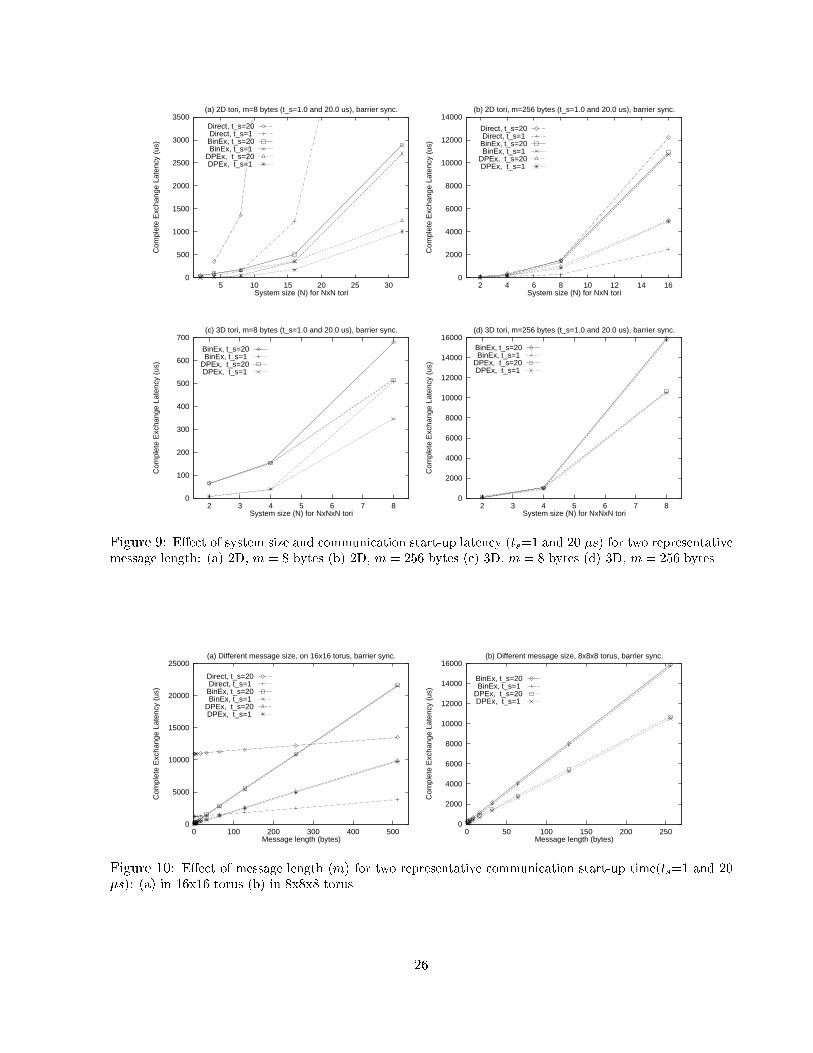
6.1 E�ect of System Size and Communication Startup LatencyFig. 9 shows the performance comparison between the synchronous version of theDiagonal Propagation()algorithm and binary exchange algorithm on various 2D and 3D tori. Fig. 9(a) and Fig. 9(b) showthe performance on 2D tori for message size of 8 and 256, respectively. Similarly, Fig. 9(c) andFig. 9(d) show the performance on 3D tori for message size of 8 and 256, respectively. Each �gureshows plots for two di�erent settings of message startup time: ts = 1�s and ts = 20�s. A barriersynchronization overhead of tbar = 1�s was assumed. For smaller message size (m = 8), bothindirect methods (DPEx and BinEx) easily outperforms Direct method because of fewer phasesused in indirect methods. However, when the message size becomes larger the memory copy costin indirect methods becomes signi�cant. Direct method with ts = 1�s performs the best whenm = 256 (Fig. 9(b)). It can also be seen that the in uence of ts on direct method is larger than onindirect method: with ts = 20�s, direct method is among the worst ones. For systems smaller than2� 2 and 4� 4� 4, DPEx performs the same as BinEx because both schemes cannot fully utilizethe communication channels. However, in bigger systems DPEx outperforms BinEx. For instance,on a 32� 32 system, DPEx is about twice as fast as BinEx (Fig. 9(a)).6.2 E�ect of Message LengthThe e�ect of message length on the performance of these algorithms on a �xed size torus is shownin Fig. 10. The start-up cost of direct method is much higher than that of indirect methods(Fig. 10(a)). However, the marginal cost on message size of direct method is smaller than that ofindirect methods because memory copy operation is needed in indirect methods. As the messagelength grows, the propagation time becomes an increasingly signi�cant component of the total�nish time. Thus, Direct method outperforms the indirect schemes for larger message size. SinceDPEx uses less bandwidth than BinEx, with the increase in the message size the performance ofDPEx relative to that of BinEx should improve on a �xed size system. This is clearly shown in theplots for a 16� 16 torus (Fig. 10(a)) and an 8� 8� 8 torus (Fig. 10(b)).6.3 E�ect of Barrier SynchronizationFig. 11 (a) and (b) show the e�ect of barrier synchronization on the performance of Diago-nal Propagation(). Each of these �gures have three lines, one for the case without barrier syn-chronization between phases and two for the case with barrier synchronization with di�erent costs:tbar = 1�s and tbar = 10�s. When the message length is larger than about 12 bytes for ts = 20�s25
0
500
1000
1500
2000
2500
3000
3500
5 10 15 20 25 30
Com
plet
e E
xcha
nge
Late
ncy
(us)
System size (N) for NxN tori
(a) 2D tori, m=8 bytes (t_s=1.0 and 20.0 us), barrier sync.
Direct, t_s=20Direct, t_s=1
BinEx, t_s=20BinEx, t_s=1
DPEx, t_s=20DPEx, t_s=1
0
2000
4000
6000
8000
10000
12000
14000
2 4 6 8 10 12 14 16
Com
plet
e E
xcha
nge
Late
ncy
(us)
System size (N) for NxN tori
(b) 2D tori, m=256 bytes (t_s=1.0 and 20.0 us), barrier sync.
Direct, t_s=20Direct, t_s=1
BinEx, t_s=20BinEx, t_s=1
DPEx, t_s=20DPEx, t_s=1
0
100
200
300
400
500
600
700
2 3 4 5 6 7 8
Com
plet
e E
xcha
nge
Late
ncy
(us)
System size (N) for NxNxN tori
(c) 3D tori, m=8 bytes (t_s=1.0 and 20.0 us), barrier sync.
BinEx, t_s=20BinEx, t_s=1
DPEx, t_s=20DPEx, t_s=1
0
2000
4000
6000
8000
10000
12000
14000
16000
2 3 4 5 6 7 8
Com
plet
e E
xcha
nge
Late
ncy
(us)
System size (N) for NxNxN tori
(d) 3D tori, m=256 bytes (t_s=1.0 and 20.0 us), barrier sync.
BinEx, t_s=20BinEx, t_s=1
DPEx, t_s=20DPEx, t_s=1
Figure 9: E�ect of system size and communication start-up latency (ts=1 and 20 �s) for two representativemessage length: (a) 2D, m = 8 bytes (b) 2D, m = 256 bytes (c) 3D, m = 8 bytes (d) 3D, m = 256 bytes.
0
5000
10000
15000
20000
25000
0 100 200 300 400 500
Com
plet
e E
xcha
nge
Late
ncy
(us)
Message length (bytes)
(a) Different message size, on 16x16 torus, barrier sync.
Direct, t_s=20Direct, t_s=1
BinEx, t_s=20BinEx, t_s=1
DPEx, t_s=20DPEx, t_s=1
0
2000
4000
6000
8000
10000
12000
14000
16000
0 50 100 150 200 250
Com
plet
e E
xcha
nge
Late
ncy
(us)
Message length (bytes)
(b) Different message size, 8x8x8 torus, barrier sync.
BinEx, t_s=20BinEx, t_s=1
DPEx, t_s=20DPEx, t_s=1
Figure 10: E�ect of message length (m) for two representative communication start-up time(ts=1 and 20�s): (a) in 16x16 torus (b) in 8x8x8 torus.26

and about 7 bytes for ts = 1�s (Fig. 11(a) and 11(b)), the synchronized version has a better per-formance. This is because the asynchronous version su�ers from link congestion in these cases.However, if we enlarge the left portion of the �gures (Fig. 11(c) and 11(d)), we see that asyn-chronous version runs faster for very small message length because of the overlapping of messageexchange time and memory rearrangement time in each phase.0
2000
4000
6000
8000
10000
12000
14000
16000
18000
0 100 200 300 400 500
Com
plet
e E
xcha
nge
Late
ncy
(us)
Message length (bytes)
(a) Different message size, 16x16 torus, t_s=20us (sync vs. async)
DPEx, asyncDPEx, sync, t_bar=10DPEx, sync, t_bar=1
0
2000
4000
6000
8000
10000
12000
14000
16000
0 100 200 300 400 500
Com
plet
e E
xcha
nge
Late
ncy
(us)
Message length (bytes)
(b) Different message size, 16x16 torus, t_s=1us (sync vs. async)
DPEx, asyncDPEx, sync, t_bar=10DPEx, sync, t_bar=1
150
200
250
300
350
400
450
500
550
600
650
0 2 4 6 8 10 12 14 16 18 20
Com
plet
e E
xcha
nge
Late
ncy
(us)
Message length (bytes)
(c) Different m, 16x16 torus, t_s=20us (sync vs. async, enlarge)
DPEx, asyncDPEx, sync, t_bar=10DPEx, sync, t_bar=1
0
50
100
150
200
250
300
350
400
450
500
550
0 2 4 6 8 10 12 14 16 18 20
Com
plet
e E
xcha
nge
Late
ncy
(us)
Message length (bytes)
(d) Different m, 16x16 torus, t_s=1us (sync vs. async, enlarge)
DPEx, asyncDPEx, sync, t_bar=10
DPEx, sync, t_bar=1
Figure 11: Comparison between synchronous and asynchronous implementations in a 16x16 torus: (a)ts=1�s, (b)ts=20�s, (c) enlargement of (a) for smaller message length, and (d) enlargement of (b) forsmaller message length.6.4 Comparison of Algorithms under Asynchronous ModelFig. 12 compares the methods under asynchronous model. Observations similar to those obtainedin Fig. 9 can also be found here, with the exception that Direct method with ts = 1�s performsmuch better than its synchronous version, and for large message size (m = 256) Direct methodperforms better than both indirect methods. For small message size (m = 8), Direct method withts = 20�s still su�ers from high start-up time and is the worst one. For a larger system size,DPEx always outperforms BinEx. However, the factor of improvement is smaller because networkcontention leads to increased complete exchange latency for both algorithms.27

0
500
1000
1500
2000
2500
3000
5 10 15 20 25 30
Com
plet
e E
xcha
nge
Late
ncy
(us)
System size (N) for NxN tori
(a) 2D tori, m=8 bytes (t_s=1.0 and 20.0 us), async
Direct, t_s=20Direct, t_s=1
BinEx, t_s=20BinEx, t_s=1
DPEx, t_s=20DPEx, t_s=1
0
1000
2000
3000
4000
5000
6000
7000
8000
9000
10000
2 4 6 8 10 12 14 16
Com
plet
e E
xcha
nge
Late
ncy
(us)
System size (N) for NxN tori
(b) 2D tori, m=256 bytes (t_s=1.0 and 20.0 us), async
Direct, t_s=20Direct, t_s=1
BinEx, t_s=20BinEx, t_s=1
DPEx, t_s=20DPEx, t_s=1
0
100
200
300
400
500
600
700
2 3 4 5 6 7 8
Com
plet
e E
xcha
nge
Late
ncy
(us)
System size (N) for NxNxN tori
(c) 3D tori, m=8 bytes (t_s=1.0 and 20.0 us), async
BinEx, t_s=20BinEx, t_s=1
DPEx, t_s=20DPEx, t_s=1
0
2000
4000
6000
8000
10000
12000
14000
16000
18000
2 3 4 5 6 7 8
Com
plet
e E
xcha
nge
Late
ncy
(us)
System size (N) for NxNxN tori
(d) 3D tori, m=256 bytes (t_s=1.0 and 20.0 us), async
BinEx, t_s=20BinEx, t_s=1
DPEx, t_s=20DPEx, t_s=1
Figure 12: E�ect of system size and communication start-up latency (ts=1 and 20 �s) for two di�erentmessage length under asynchronous model: (a) 2D, m = 8 bytes (b) 2D, m = 256 bytes (c) 3D, m = 8 bytes(d) 3D, m = 256 bytes.
0
2000
4000
6000
8000
10000
12000
14000
16000
18000
0 100 200 300 400 500
Com
plet
e E
xcha
nge
Late
ncy
(us)
Message length (bytes)
Different memory copy cost, 16x16 torus, t_s=20us
DPEx, async, t_r=0.0050DPEx, async, t_r=0.0025
DPEx, sync, t_bar=10, t_r=0.0050DPEx, sync, t_bar=10, t_r=0.0025
Figure 13: Impact of processor-memory bus bandwidth on DPEx algorithms on 16x16 torus with ts=20�s.28
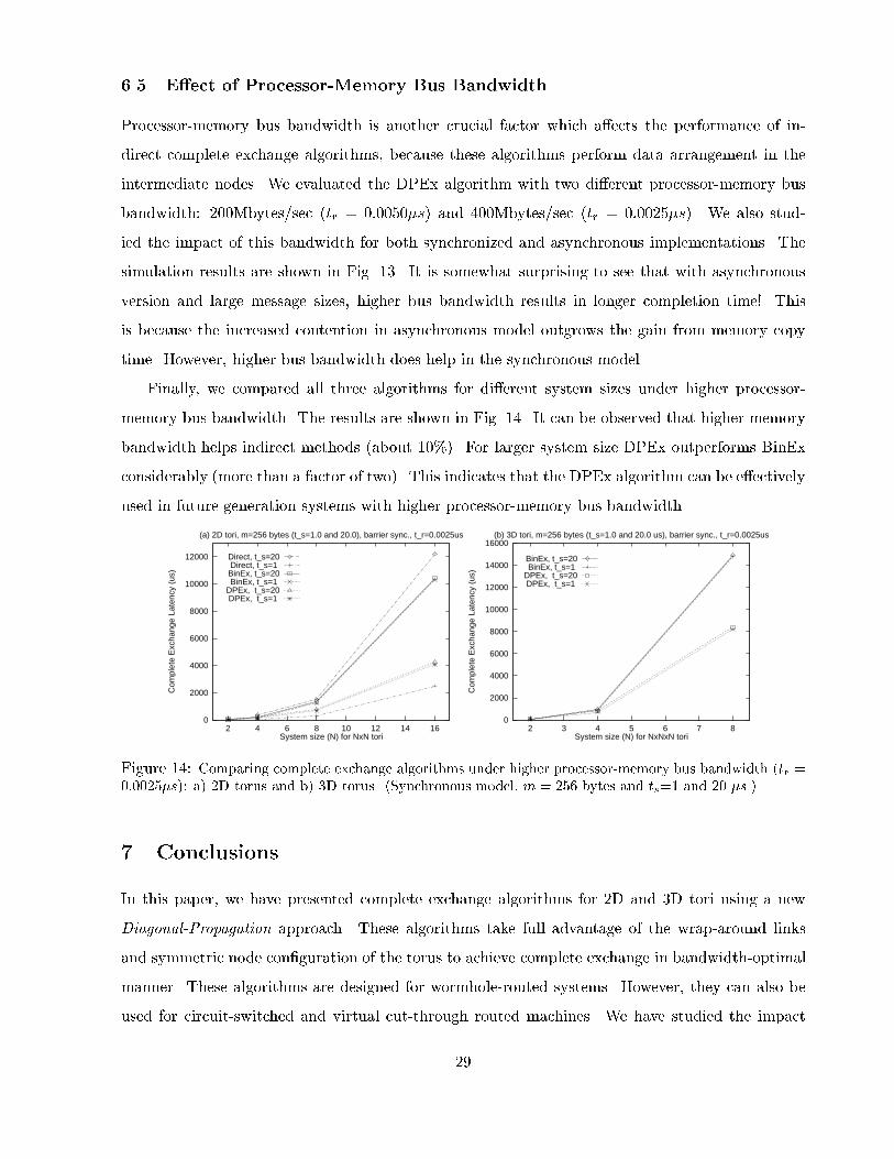
6.5 E�ect of Processor-Memory Bus BandwidthProcessor-memory bus bandwidth is another crucial factor which a�ects the performance of in-direct complete exchange algorithms, because these algorithms perform data arrangement in theintermediate nodes. We evaluated the DPEx algorithm with two di�erent processor-memory busbandwidth: 200Mbytes/sec (tr = 0:0050�s) and 400Mbytes/sec (tr = 0:0025�s). We also stud-ied the impact of this bandwidth for both synchronized and asynchronous implementations. Thesimulation results are shown in Fig. 13. It is somewhat surprising to see that with asynchronousversion and large message sizes, higher bus bandwidth results in longer completion time! Thisis because the increased contention in asynchronous model outgrows the gain from memory copytime. However, higher bus bandwidth does help in the synchronous model.Finally, we compared all three algorithms for di�erent system sizes under higher processor-memory bus bandwidth. The results are shown in Fig. 14. It can be observed that higher memorybandwidth helps indirect methods (about 10%). For larger system size DPEx outperforms BinExconsiderably (more than a factor of two). This indicates that the DPEx algorithm can be e�ectivelyused in future generation systems with higher processor-memory bus bandwidth.0
2000
4000
6000
8000
10000
12000
2 4 6 8 10 12 14 16
Com
plet
e E
xcha
nge
Late
ncy
(us)
System size (N) for NxN tori
(a) 2D tori, m=256 bytes (t_s=1.0 and 20.0), barrier sync., t_r=0.0025us
Direct, t_s=20Direct, t_s=1
BinEx, t_s=20BinEx, t_s=1
DPEx, t_s=20DPEx, t_s=1
0
2000
4000
6000
8000
10000
12000
14000
16000
2 3 4 5 6 7 8
Com
plet
e E
xcha
nge
Late
ncy
(us)
System size (N) for NxNxN tori
(b) 3D tori, m=256 bytes (t_s=1.0 and 20.0 us), barrier sync., t_r=0.0025us
BinEx, t_s=20BinEx, t_s=1
DPEx, t_s=20DPEx, t_s=1
Figure 14: Comparing complete exchange algorithms under higher processor-memory bus bandwidth (tr =0:0025�s): a) 2D torus and b) 3D torus. (Synchronous model, m = 256 bytes and ts=1 and 20 �s.)7 ConclusionsIn this paper, we have presented complete exchange algorithms for 2D and 3D tori using a newDiagonal-Propagation approach. These algorithms take full advantage of the wrap-around linksand symmetric node con�guration of the torus to achieve complete exchange in bandwidth-optimalmanner. These algorithms are designed for wormhole-routed systems. However, they can also beused for circuit-switched and virtual cut-through routed machines. We have studied the impact29

of various system and technological parameters on the performance of these complete exchangealgorithms. These results indicate that the new algorithms can reduce complete exchange latencyup to a factor of two. We have also investigated synchronous and asynchronous implementations ofthese algorithms. The study indicates that synchronous implementation is bene�cial for completeexchange with a larger message length. The design guidelines provided in this paper can be usedto generalize these algorithms to tori of higher dimensions or non power-of-two sizes. But it is stillopen to develop a good message arrangement rule for the non power-of-two cases. Another futureresearch direction is to consider tori that are non-square. The di�culty in our approach to dealwith such cases is that there is no good de�nition of \diagonal" in a non-square torus.AcknowledgmentsDr. Yu-Chee Tseng's research is supported by the National Science Council of the Republic of Chinaunder Grant # NSC86-2213-E-008-029 and Grant # NSC86-2213-E-216-021. Dr. Panda's researchis supported in part by the National Science Foundation Faculty Early CAREER DevelopmentAward, MIP - 9502294.References[1] G. Bilardi and F. P. Preprata. "Horizons of Parallel Computation". J. of Parallel and Dis-tributed Computing, 27:172{182, 1995.[2] S. H. Bokhari and H. Berryman. "Complete Exchange on a Circuit Switched Mesh". InScalable High Performance Computing Conf., pages 300{306, 1992.[3] S. Borkar, R. Cohn, G. Cox, S. Gleason, T. Gross, H. T. Kung, B. M. M. Lam, C. Peterson,J. Pieper, L. Rankin, P. S. Tseng, J. Sutton, J. Urbanski, and J. Webb. "iWarp: An integratedsolution to high-speed parallel computing". In Proceedings of Supercomputing '88, pages 330{339. IEEE Computer Society and ACM SIGARCH, November 1988.[4] Cray Research, Inc. Cray T3D System Architecture Overview, 1993.[5] W. J. Dally, R. Davison, J. A. S. Fiske, G. Fyler, J. S. Keen, R. A. Lethin, M. Noakes, andP. R. Nuth. "The J-Machine: A Fine-grain Concurrent Computer". In Information Processing89, IFIP, pages 1147{1153, 1989.30

[6] W. J. Dally and C. L. Seitz. "The Torus Routing Chip". J. of Parallel and Distrib. Comput.,1(3):187{196, 1986.[7] I. Foster. Designing and Building Parallel Programs: Concepts and Tools for Parallel SoftwareEngineering. Addison Wesley, Reading, Massachusetts, 1994.[8] P. Fragopoulou and S. G. Akl. "A Framework for Optimal Communication on the Multidi-mensional Torus Network". Technical Report 94-363, Dept. of Computing and InformationScience, Queen's Univeristy, 1994.[9] S. Gupta, S. Hawkinson, and B. Baxter. "A Binary Interleaved Algorithm for CompleteExchange on a Mesh Architecture". Technical report, Intel Corporation, 1994.[10] S. Hinrichs, C. Kosak, D. R. O'Hallaron, T. M. Stricker, and R. Take. "An Architecture forOptimal All-to-All Personalized Communication". In Symp. on Parallel Algo. and Arch., pages310{319, 1994.[11] H. Li and M. Maresca. "Polymorphic-Torus Network". IEEE Trans. on Computing,38(9):1345{1351, Sept. 1989.[12] M. Lin, R. P. Tsang, and D. Du. "Performance Characteristics of the Connection MachineHypertree Network". J. of Parallel and Distributed Computing, 19:245{254, 1993.[13] MasPar Computer Co. "MP-1 Family Data-parallel Computers".[14] Message Passing Interface Forum. MPI: A Message-Passing Interface Standard, March 1994.[15] L. M. Ni and P. K. McKinley. A survey of wormhole routing techniques in direct networks.IEEE Computer, 26:62{76, Feb. 1993.[16] W. Oed. Massively Parallel Processor System Cray T3D. Cray Research GmbH, 1993.[17] D. S. Scott. "E�cient All-to-All Communication Patterns in Hypercube and Mesh Topologies".In IEEE Distributed Memory Conference, pages 398{403, 1991.[18] S. R. Seidel. "Circuit Switched vs. Store-and-forward Solutions to Symmetric CommunicationProblems". In 4th Conf. Hypercube Concurrent Computers and Applications, pages 253{255,1989. 31
[19] N. S. Sundar, D. N. Jayasimha, D. K. Panda, and P. Sadayappan. "Complete Exchange in 2DMeshes". In Scalable High Perf. Comput. Conf., pages 406{413, 1994.[20] M. R. Thistle and B. J. Smith. "A Processor Architecture for Horizon". In Supercomputing,pages 35{41, 1988.[21] Y.-C. Tseng and S. K. S. Gupta. "All-to-All Personalized Communication in a Wormhole-routed Torus". IEEE Trans. on Parallel and Distributed Systems, 7(5):498{505, May 1996.[22] Y.-C. Tseng, S. K. S. Gupta, and D. K. Panda. "An E�cient Scheme for Complete Exchangein 2D Tori". In Int'l Parallel Processing Symp., pages 532{536, 1995.
32


![Detecting wormhole attacks in 3D wireless ad hoc …19 Wormhole...Recently proposed wormhole detection algorithms focus on wireless network coding system [1], delay tolerant net- works](https://img.pdfslide.us/doc/110x75/5fd567e514077f0a20239b9e/detecting-wormhole-attacks-in-3d-wireless-ad-hoc-19-wormhole-recently-proposed.jpg)