Embed Size (px)
Citation preview

IJIREEICE ISSN (Online) 2321 – 2004 ISSN (Print) 2321 – 5526
INTERNATIONAL JOURNAL OF INNOVATIVE RESEARCH IN ELECTRICAL, ELECTRONICS, INSTRUMENTATION AND CONTROL ENGINEERING Vol. 3, Issue 12, December 2015
Copyright to IJIREEICE DOI 10.17148/IJIREEICE.2015.31233 160
Bandwidth Improvement of Dual Band Printed
Rectangular Monopole Antenna
Vijayalakshmi Hunnur1, Akanksha Agrawal
2, Darpan Savla
3, Mahima Kaul
4, Jyoti Kori
5
Student, Department of Electronics, Thakur College of Engineering & Technology, Mumbai, India 1,2,3,4
Assistant Professor, Department of Electronics, Thakur College of Engineering & Technology, Mumbai, India5
Abstract: This paper describes the design of the printed rectangular monopole antenna using inset field in rectangular
shape operating at 2.4 GHz. The dimensions of each single element of the planar monopole antenna at the operating
frequency are calculated using transmission line model. Broadband planar monopole antennas have all the advantages
of the monopole in terms of their cost, and ease of fabrication besides, yielding very large bandwidths. For many
applications large bandwidth is required. Recently, many techniques to tailor and optimize the impedance BW of these
antennas have been investigated. These antennas are becoming popular, and have been proposed for modern and future
wideband wireless applications. The radiation performance is also shown to be acceptable over a wide range of
frequency. Optimization of the feed point location can achieve very compact configurations. Also these antennas can
provide band-notching characteristics. These antennas have been reported to provide multi band characteristics too.
More recently, it has been shown that, although the square monopole (SM) provides smaller BW than the circular
monopole (CM), its radiation pattern suffers less degradation within the impedance BW.
Keywords: Printed Rectangular Monopole antenna, antenna feeds, Slot cut, offset feed and broadband antenna.
I. INTRODUCTION
Today’s world demands antennas that are diminutive but
provide a wide impedance bandwidth for greater number
of applications. Planar monopole antenna sees its
applications in many wireless communication services
because of its wide impedance bandwidth, compact simple
structure and ease of fabrication [1-7]. A printed
configuration of the rectangular monopole antenna has
been reported along with its parametric studies. The main
purpose of this paper was to optimize the bandwidth of the
Rectangular printed monopole antennas (PRMA). The
geometrical configurations of PRMA were varied to obtain
a higher bandwidth for wide-band applications.
Previously reported printed rectangular monopole antenna
[1-3] have given detailed study of all regular geometries of
printed monopole antenna (PMA) with various feed
positions and its effect on impedance bandwidth. The
effect of feed configuration is also a critical parameter in
determining the performance of the PMA. The feed was
offsetted and varied of the rectangular monopole antenna
and also of the modified geometry to achieve VSWR<=2
which is in good agreement with the experimental results.
The optimized configuration of PRMA gives the
bandwidth of 6.6GHz for VSWR <= 2.
This band is very useful for many wireless applications,
which includes GSM1900, WCDMA (1.92 to 2.17 GHz),
ISM band (2.4 to 2.4853 GHz), Wi-Fi band (2.4, 3.5 and 5
GHz) [10,11].
II. GEOMETRY OF PROPOSED PRINTED
RECTANGULAR MONOPOLE ANTENNA
A rectangular monopole antenna of size 50mm X 40mm
was fabricated on a glass epoxy (FR4) substrate of 70mm
X 70mm with thickness = 1.59mm, dielectric constant =
4.3 and loss tangent tan = 0.01. The ground plane is of
size 70mm X 10mm. The feed point’s widths were
simulated for 0.5 mm, 1mm and 2mm and the optimized
width was accepted for 1mm wide [2]. The antenna is fed
using 50-Ohm micro strip line of 3mm length above the
ground plane [3]. The effect of ground plane length is
negligible on bandwidth, so it was reduced from 20mm to
10mm [10, 11]. Therefore length of ground plane is fixed
at 10mm for reduced size of the substrate. The PRMA is
simulated by using IE3D software[8,9] for various feed
position with offsets (0mm to 8mm) and slot lengths (4mm
to 12mm) and it’s effect on bandwidth is studied.
The following sets of formulas are used to obtain the value
of:
(1) Length (L) of the antenna
(2) Width (W) of the antenna
(3)εreff
With the known data as:
c=3*10^8 m/sec
ε=2.2
fo=2.4GHz
h=1.58 mm
fo =c
2 εreff (
m
L)2 +
n
W
2
1
2 (1)
Where m and n are modes along L and W respectively.
For efficient radiation, the width W is given by Bahl and
Bhartia as:
W = 𝐜
𝟐𝐟𝐨 (𝛆𝐫+𝟏)
𝟐
(2)
We get W=40.15
The effective length of the patch Leff now becomes:
Leff = L + 2∆L (3)
For a given resonance frequency fc, the effective length is
given by:

IJIREEICE ISSN (Online) 2321 – 2004 ISSN (Print) 2321 – 5526
INTERNATIONAL JOURNAL OF INNOVATIVE RESEARCH IN ELECTRICAL, ELECTRONICS, INSTRUMENTATION AND CONTROL ENGINEERING Vol. 3, Issue 12, December 2015
Copyright to IJIREEICE DOI 10.17148/IJIREEICE.2015.31233 161
L= c
2fo εreff (4)
Leff = 40.34mm L=50 mm.
From the above-calculated values, the rectangular
monopole antenna was designed. The proposed printed
rectangular monopole antenna is shown in figures 2,3 and
4. The feed point position is fixed at 6 mm on the right of
the center. The effect of feed point variation is the same on
either side of the center. The lower cut-off frequency at
distance of 6mm of the feed point is 3.68702 GHz.
After fabrication of this antenna, a SMA connector 7855
FEMALE is connected between the feed point of the
antenna and the ground patch of the antenna. This ensures
the connection of the feed circuit with the conductor.
Since the antenna fabricated is a dual band antenna, two
different frequency bands are obtained; one for the lower
frequency and one for the higher frequency, for VSWR=2.
Rather than centre resonance frequency, lower edge
frequency is calculated for planar monopole antenna [10].
The lower band edge frequency of planar monopole
antennas for VSWR =2 is obtained by equating the area of
the PRMA with that of its equivalent cylindrical monopole
antenna of same height L and equivalent radius r [10] and
is as given below:
2πrL = WL (5)
Which gives,
r = W/2π (6)
The input impedance of a λ /4 monopole antennas is half
of that of the λ /2 dipole antenna. Thus, the input
impedance of an infinitesimally thin monopole antenna is
36.5 + j 21.25Ω, which is inductive. The real input
impedance is obtained when a slightly smaller length of
the monopole is used as given by:
L= 0.24 λF (7)
Where
F = (L/r) / (1 + L/r) = L/ (L + r) (8)
From (3) and (4), the wavelength λ is obtained as
λ = (L + r)/0.24 (9)
Therefore, the lower frequency fL is given by
fL = c/ λ = 7.2/(L + r ) GHz (10)
Equation (6) does not account for the effect of the probe
length p, which increases the total length of the antenna
thereby reducing the frequency. Accordingly, this equation
is modified to
fL= 7.2/(L + r + p) GHz (11)
Where L, r and pare in centimetres. But the monopole is
fabricated on a substrate, thus
fL = 7.2/ ( L + r + p)k GHz (12)
Where k is the correction factor, k=1.15 for FR4 substrate
with εr = 4.3 and h = 0.159 cm [1-3].
III. PARAMETRIC STUDY AND RESULTS
Printed Monopole Antennas are designed keeping in mind
a lot of parameters that will affect the performance
characteristics of the antenna. There are many parameters,
which play a vital role in measurement of the performance
of the antenna functioning and thereby help in proper
measurement of its performance. The radiation pattern,
VSWR curve, Smith chart and Impedance circle were
observed and compared for all values. The PRMA is first
set to a particular value of L and W that is derived from
the formulas mentioned above. The following parameters
were varied to obtain an antenna with optimized values.
A. Offset Feed
The For two different feed-point locations from the center
of the antenna, variations in the input impedance Zin and
VSWR with frequency millimetres are observed. With an
increase in frequency, the input impedance moves in the
clockwise direction in the Smith chart. VSWR graph was
generated for the above design with different feed point
positions and compared all the results of the PRMA and
finally selected the best design amongst them keeping in
mind the VSWR Graph formed. To display the effect of
feed position on impedance bandwidth, corresponding
VSWR plots are shown in figure 1. Hence, from the above
comparison of various VSWR graphs, feed point was
narrowed down to one at 6mm from the center.
As the feed point was varied from the center to the right
corner, VSWR value varied from VSWR=1.989 to
VSWR=1.08, which is close to the value of VSWR ≤ 2.
Fig.1. VSWR Graph at various feed point locations
observed using IE3D software.
After locating the optimized feed point location using
them Analyzer’ to find the actual VSWR of the antenna.
B. Geometrical variation in PRMA
The geometrical variation or shape has great effects on the
bandwidth of the antenna [10,11]. In this paper the shape
of the PRMA is varied to measure the change in
bandwidth. The conventional PRMA measuring
50mmX40mm is fabricated on the FR4 substrate as shown
in figure 1.
Fig.2. Geometry of Printed Rectangular Monopole
Antenna

IJIREEICE ISSN (Online) 2321 – 2004 ISSN (Print) 2321 – 5526
INTERNATIONAL JOURNAL OF INNOVATIVE RESEARCH IN ELECTRICAL, ELECTRONICS, INSTRUMENTATION AND CONTROL ENGINEERING Vol. 3, Issue 12, December 2015
Copyright to IJIREEICE DOI 10.17148/IJIREEICE.2015.31233 162
Further, a slot in created at the center of the PRMA. Slot
width is kept constant at 4mm and slot length is varied
from 4mm to 12mm as shown in figure 3. After varying
the values, the slot length was considered to be 9 mm. The
slot helps in reducing the return loss of the antenna and
hence, achieving the optimum results.
Fig. 3. Geometry of PRMA with slot at the center.
The geometry of the PRMA was further varied for
increasing the bandwidth. The bottom left and right
corners of the PRMA with the slot were rounded with a
radius of 18mm as in figure 4.
Fig. 4. Geometry of PRMA with slot at center and
rounded base.
The bandwidth of the circular PRMA with slot and
rounded base is in the range of 2 GHz to 7 GHz
approximately.
(1) Printed Rectangular Monopole Antenna:
VSWR:
Fig.5. VSWR Graph at optimum feed point location using
IE3D
The geometry of the PRMA after testing was found to be
radiating at 2 values of frequency amongst which, the first
peak lies approximately close to desired set frequency
through our IE3D software. The 2 frequencies at which the
antenna radiates maximum is 2.26 GHz and 4.20 GHz.
VSWR=1.989 and VSWR=1.903 respectively.
Fig.6. VSWR Graph obtained practically at optimum feed
point location
Return Loss:
Fig.7. Return Loss Graph obtained practically at optimum
feed point location
Return loss at 2.46 GHz is -17.35 dB
Return loss at 4.20 GHz is -35.819 dB
The return loss for the above geometry at the two bands is
less than -10dB (-10dB corresponds to a VSWR of 2
which is an acceptable figure)
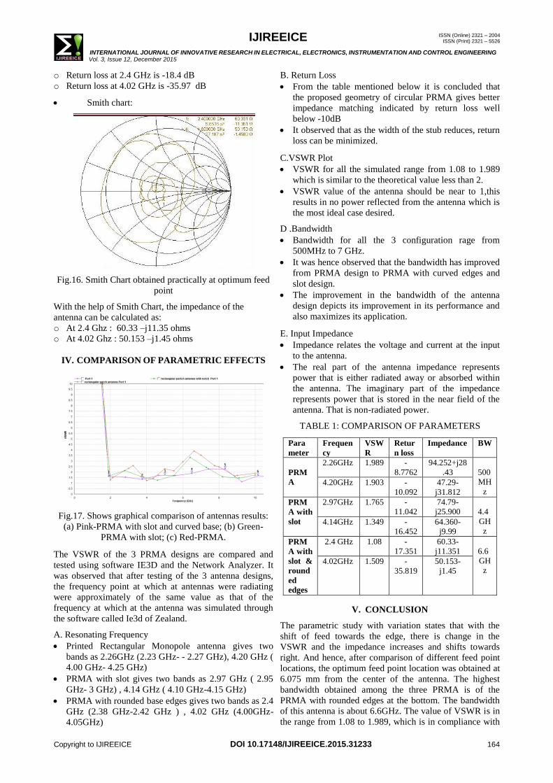
Smith Chart:
Fig.8. Smith Chart obtained practically at optimum feed
point location
With the help of Smith Chart, the impedance of the
antenna is calculated as:
4mm
9m
m
R=18mm

IJIREEICE ISSN (Online) 2321 – 2004 ISSN (Print) 2321 – 5526
INTERNATIONAL JOURNAL OF INNOVATIVE RESEARCH IN ELECTRICAL, ELECTRONICS, INSTRUMENTATION AND CONTROL ENGINEERING Vol. 3, Issue 12, December 2015
Copyright to IJIREEICE DOI 10.17148/IJIREEICE.2015.31233 163
At 2.26 Ghz : 60.33-j11.351 ohms
At 4.20 GHz: 50.153-j1.45 ohms.
(2) PRMA with slot:
VSWR:
Fig.9. VSWR Graph at optimum feed point location using
IE3D
The 2 frequencies at which the antenna radiates maximum
is 2.79 GHz and 4.14 GHz and VSWR=1.765 and
VSWR=1.349.
Return Loss:
Fig.11. Return Loss obtained at optimum feed point
location
Return loss at 2.79 GHz is -11.042 dB
Return loss at 4.14 GHz is -16.452 dB
Smith Chart:
With the help of Smith Chart, the impedance of the
antenna was calculated as:
At 2.79 Ghz : 74.79 – j25.9 ohms
At 4.14 Ghz : 64.3 – j9.9 ohms
Fig.12. Smith Chart obtained practically at optimum feed
point location
(3) PRMA with curved edges and slot:
VSWR:
Fig.13. VSWR Graph at optimum feed point location
using IE3D
The 2 frequencies at which our antenna radiates maximum
are 2.4 GHz and 4.02 GHz.
Fig.14. VSWR Graph obtained practically at optimum
feed point
Return Loss
Fig.15. Return Loss obtained practically at optimum feed
point
Fig.10.VSWR Graph obtained practically at optimum
feed point
IJIREEICE ISSN (Online) 2321 – 2004 ISSN (Print) 2321 – 5526
INTERNATIONAL JOURNAL OF INNOVATIVE RESEARCH IN ELECTRICAL, ELECTRONICS, INSTRUMENTATION AND CONTROL ENGINEERING Vol. 3, Issue 12, December 2015
Copyright to IJIREEICE DOI 10.17148/IJIREEICE.2015.31233 164
o Return loss at 2.4 GHz is -18.4 dB
o Return loss at 4.02 GHz is -35.97 dB
Smith chart:
Fig.16. Smith Chart obtained practically at optimum feed
point
With the help of Smith Chart, the impedance of the
antenna can be calculated as:
o At 2.4 Ghz : 60.33 –j11.35 ohms
o At 4.02 Ghz : 50.153 –j1.45 ohms
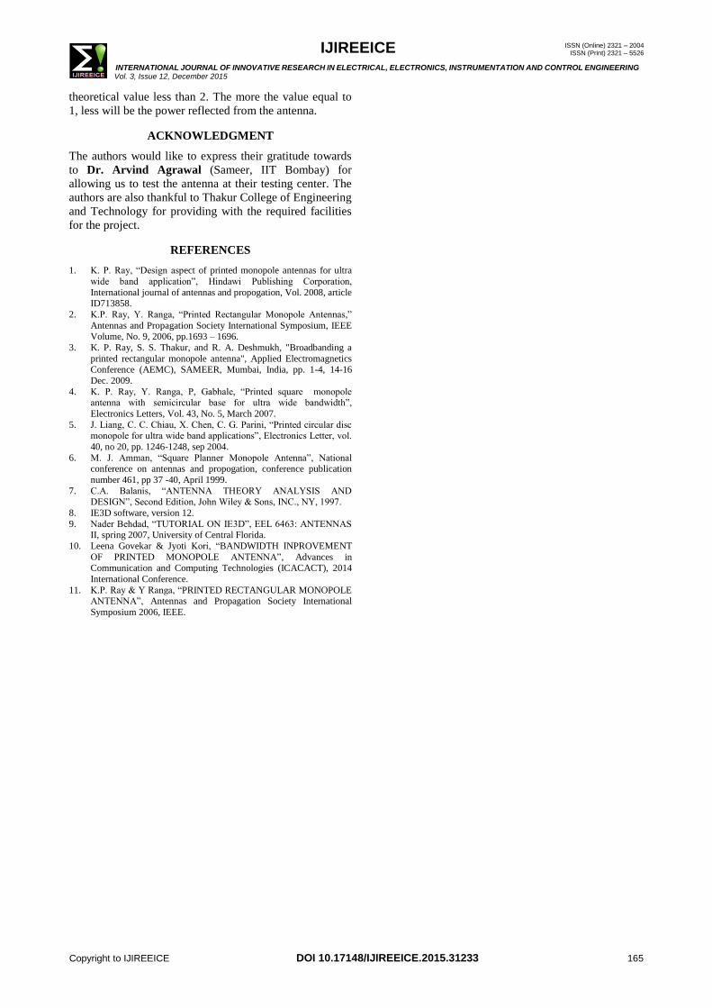
IV. COMPARISON OF PARAMETRIC EFFECTS
Fig.17. Shows graphical comparison of antennas results:
(a) Pink-PRMA with slot and curved base; (b) Green-
PRMA with slot; (c) Red-PRMA.
The VSWR of the 3 PRMA designs are compared and
tested using software IE3D and the Network Analyzer. It
was observed that after testing of the 3 antenna designs,
the frequency point at which at antennas were radiating
were approximately of the same value as that of the
frequency at which at the antenna was simulated through
the software called Ie3d of Zealand.
A. Resonating Frequency
Printed Rectangular Monopole antenna gives two
bands as 2.26GHz (2.23 GHz- - 2.27 GHz), 4.20 GHz (
4.00 GHz- 4.25 GHz)
PRMA with slot gives two bands as 2.97 GHz ( 2.95
GHz- 3 GHz) , 4.14 GHz ( 4.10 GHz-4.15 GHz)
PRMA with rounded base edges gives two bands as 2.4
GHz (2.38 GHz-2.42 GHz ) , 4.02 GHz (4.00GHz-
4.05GHz)
B. Return Loss
From the table mentioned below it is concluded that
the proposed geometry of circular PRMA gives better
impedance matching indicated by return loss well
below -10dB
It observed that as the width of the stub reduces, return
loss can be minimized.
C.VSWR Plot
VSWR for all the simulated range from 1.08 to 1.989
which is similar to the theoretical value less than 2.
VSWR value of the antenna should be near to 1,this
results in no power reflected from the antenna which is
the most ideal case desired.
D .Bandwidth
Bandwidth for all the 3 configuration rage from
500MHz to 7 GHz.
It was hence observed that the bandwidth has improved
from PRMA design to PRMA with curved edges and
slot design.
The improvement in the bandwidth of the antenna
design depicts its improvement in its performance and
also maximizes its application.
E. Input Impedance
Impedance relates the voltage and current at the input
to the antenna.
The real part of the antenna impedance represents
power that is either radiated away or absorbed within
the antenna. The imaginary part of the impedance
represents power that is stored in the near field of the
antenna. That is non-radiated power.
TABLE 1: COMPARISON OF PARAMETERS
Para
meter
Frequen
cy
VSW
R
Retur
n loss
Impedance BW
PRM
A
2.26GHz
1.989 -
8.7762
94.252+j28
.43
500
MH
z 4.20GHz 1.903 -
10.092
47.29-
j31.812
PRM
A with
slot
2.97GHz 1.765 -
11.042
74.79-
j25.900
4.4
GH
z 4.14GHz
1.349 -
16.452
64.360-
j9.99
PRM
A with
slot &
round
ed
edges
2.4 GHz 1.08 -
17.351
60.33-
j11.351
6.6
GH
z 4.02GHz 1.509 -
35.819
50.153-
j1.45
V. CONCLUSION
The parametric study with variation states that with the
shift of feed towards the edge, there is change in the
VSWR and the impedance increases and shifts towards
right. And hence, after comparison of different feed point
locations, the optimum feed point location was obtained at
6.075 mm from the center of the antenna. The highest
bandwidth obtained among the three PRMA is of the
PRMA with rounded edges at the bottom. The bandwidth
of this antenna is about 6.6GHz. The value of VSWR is in
the range from 1.08 to 1.989, which is in compliance with
IJIREEICE ISSN (Online) 2321 – 2004 ISSN (Print) 2321 – 5526
INTERNATIONAL JOURNAL OF INNOVATIVE RESEARCH IN ELECTRICAL, ELECTRONICS, INSTRUMENTATION AND CONTROL ENGINEERING Vol. 3, Issue 12, December 2015
Copyright to IJIREEICE DOI 10.17148/IJIREEICE.2015.31233 165
theoretical value less than 2. The more the value equal to
1, less will be the power reflected from the antenna.
ACKNOWLEDGMENT
The authors would like to express their gratitude towards
to Dr. Arvind Agrawal (Sameer, IIT Bombay) for
allowing us to test the antenna at their testing center. The
authors are also thankful to Thakur College of Engineering
and Technology for providing with the required facilities
for the project.
REFERENCES
1. K. P. Ray, “Design aspect of printed monopole antennas for ultra
wide band application”, Hindawi Publishing Corporation,
International journal of antennas and propogation, Vol. 2008, article ID713858.
2. K.P. Ray, Y. Ranga, “Printed Rectangular Monopole Antennas,”
Antennas and Propagation Society International Symposium, IEEE
Volume, No. 9, 2006, pp.1693 – 1696.
3. K. P. Ray, S. S. Thakur, and R. A. Deshmukh, "Broadbanding a
printed rectangular monopole antenna", Applied Electromagnetics Conference (AEMC), SAMEER, Mumbai, India, pp. 1-4, 14-16
Dec. 2009.
4. K. P. Ray, Y. Ranga, P, Gabhale, “Printed square monopole antenna with semicircular base for ultra wide bandwidth”,
Electronics Letters, Vol. 43, No. 5, March 2007.
5. J. Liang, C. C. Chiau, X. Chen, C. G. Parini, “Printed circular disc monopole for ultra wide band applications”, Electronics Letter, vol.
40, no 20, pp. 1246-1248, sep 2004.
6. M. J. Amman, “Square Planner Monopole Antenna”, National conference on antennas and propogation, conference publication
number 461, pp 37 -40, April 1999.
7. C.A. Balanis, “ANTENNA THEORY ANALYSIS AND DESIGN”, Second Edition, John Wiley & Sons, INC., NY, 1997.
8. IE3D software, version 12.
9. Nader Behdad, “TUTORIAL ON IE3D”, EEL 6463: ANTENNAS II, spring 2007, University of Central Florida.
10. Leena Govekar & Jyoti Kori, “BANDWIDTH INPROVEMENT
OF PRINTED MONOPOLE ANTENNA”, Advances in
Communication and Computing Technologies (ICACACT), 2014
International Conference.
11. K.P. Ray & Y Ranga, “PRINTED RECTANGULAR MONOPOLE ANTENNA”, Antennas and Propagation Society International
Symposium 2006, IEEE.