Embed Size (px)
Citation preview
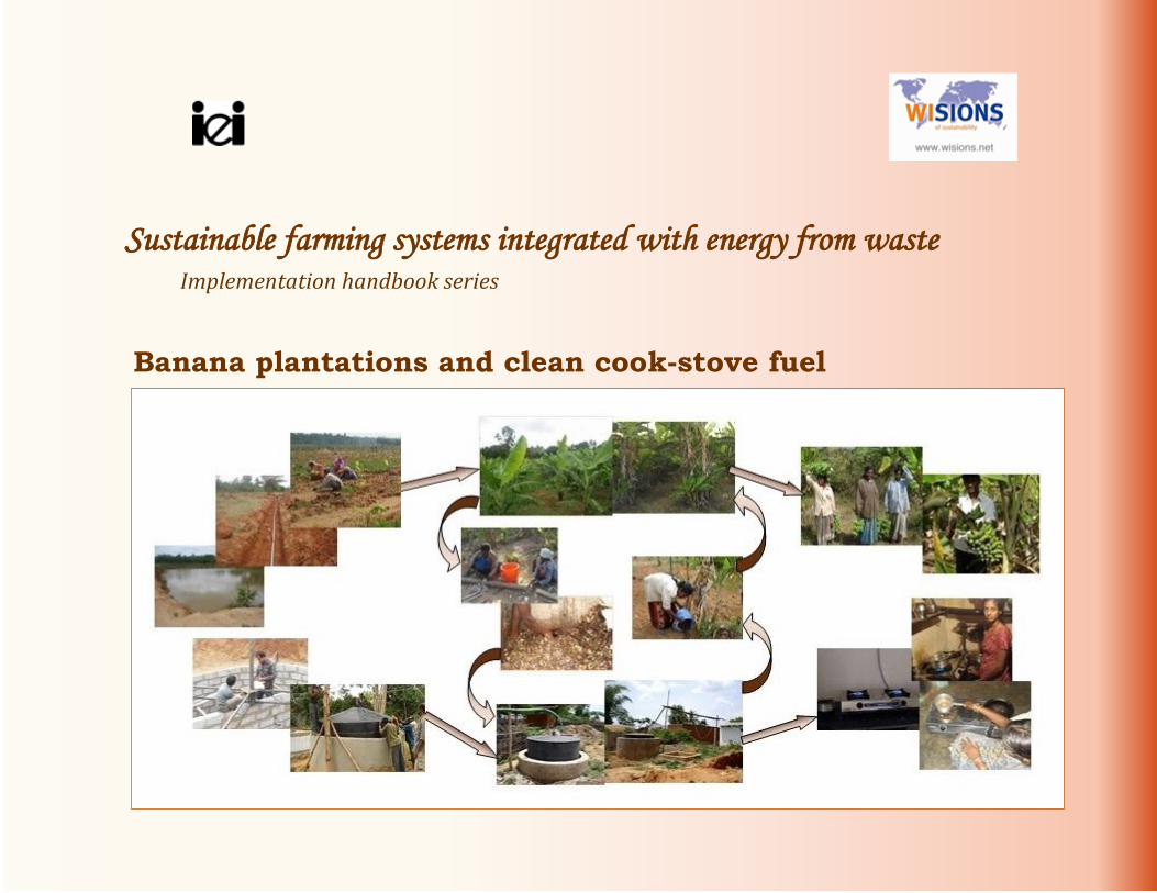
Sustainable farming systems integrated with energy from waste Implementation handbook series
Banana plantations and clean cook-stove fuel

In this Handbook:
INTRODUCTION Sustainable farming systems and energy from waste 2 Biogas 4
PRE-REQUISITES FOR BANANA GROWING AND GENERATING BIOGAS FOR STOVE-FUEL Accessing water sustainably 8
Substrate for biogas generation 10
Gas for stove-fuelling 12
Banana growing 13
BANANA CULTIVATION ACTIVITIES Pre-planting 16
At planting 20
During plant growth 22
BIOGAS GENERATION ACTIVITIES Types of biogas plants 26
Selected option – masonry-lined digester with guided floating-drum 30
Steps in the construction/installation of a masonry-lined-digester with guided floating-drum 33
Gas delivery 43
Operation and maintenance of the biogas generation system 47
TOWARDS INVESTMENT Costs and revenues 54
Funding 56
Financing 58 Farming insurance 59
Further reading 62

INTRODUCTION
IEI-Asia 1
INTRODUCTION
Sustainable farming systems and energy from waste
Biogas
What is biogas?
Advantages of biogas generation in farming regions
Biogas generation for stove-fuel in India
2 IEI-Asia
Sustainable farming systems and energy from waste
Enhancing agricultural output and employment would help the large population dependent on farming, particularly in countries like
India; growing more food is obviously good for all.
But to continue farming the same fields without reducing harvests over time, i.e. for “sustainable farming”, resources must be used
efficiently (in terms of output per unit of input).
If the by-products of these activities could also be used productively, resource-use would be even more effective.
=> Sustainable farming systems include those practices that use (and re-use) resources efficiently, enabling continued
operation and environmental preservation. Components of such systems include crop-rotation to conserve soil nutrients, efficient watering methods to conserve water, and so
on. Even more important are feedback loops: for example, rearing livestock with the residues of crops as fodder and the use of
animal excreta for fertilizing those croplands.
Here, the focus is on sustainable farming systems integrated with energy from waste.
This means that sustainable farm practices are supplemented with the generation of fuel from farm residues (usually
considered waste), for powering energy services. For example, dried stalks can be converted to producer gas, and dung or
moist vegetative waste to biogas, that can fuel electricity generators.
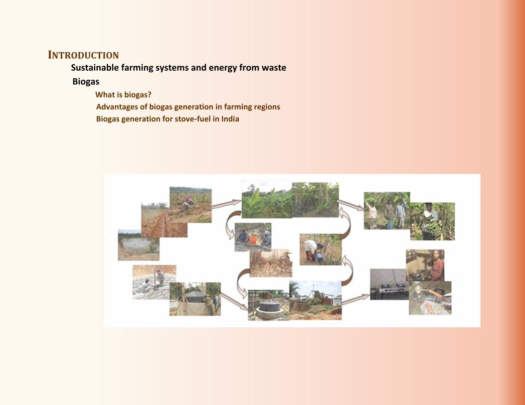
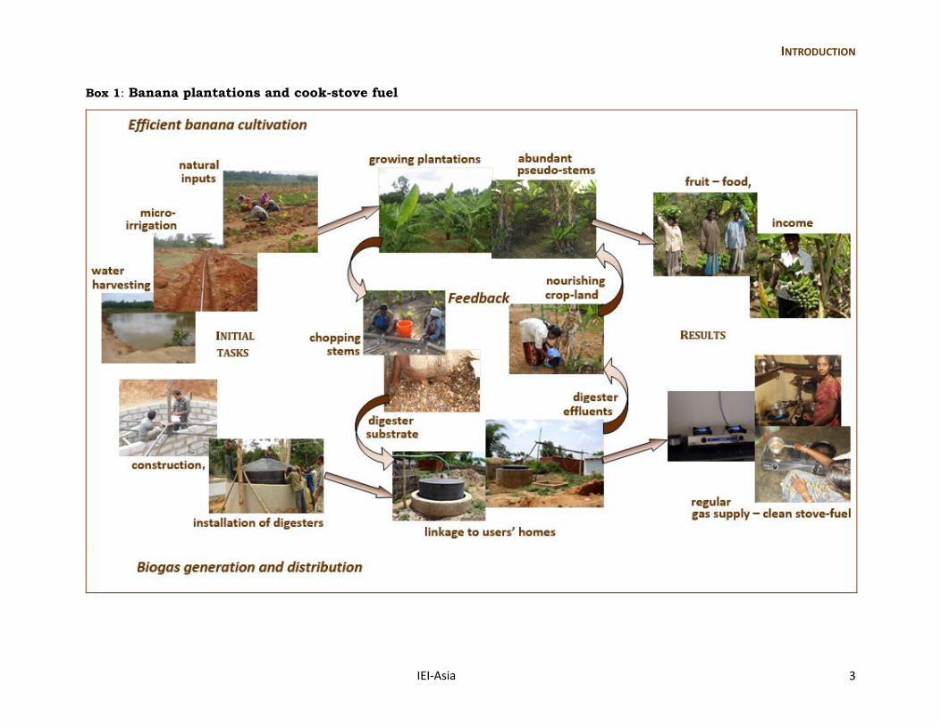
Banana-plantations and cook-stove fuel (depicted in Box 1) consists of:
efficient cultivation => conversion of plantation wastes to biogas => use of digester waste (effluents)
of bananas for stove fuel to nourish the crop lands
In this “how to” handbook, the emphasis is on:
- integrated banana growing, biogas generation, and stove-fuel delivery - family-/community-/village-level operation, rather than industrial scale (where there would be additional issues such as the
handling of high volumes of material) - actual establishment and operation in India (with appropriate approximations, rather than laboratory precision). Examples are from the projects implemented by IEI-Asia in the state of Karnataka in south India (IEI-Asia, 2008; 2012; 2014; 2016).
Note: For those interested in more details, Further Reading (pp.62-64) provides a list of papers/reports.
INTRODUCTION
IEI-Asia 3
Box 1: Banana plantations and cook-stove fuel
4 IEI-Asia
Biogas
What is biogas?
The term bio-gas refers to a combination of gases -- 50-65% methane (CH4) and 25-40% carbon dioxide (CO2), along with water
vapour (H2O) and traces of other compounds – that result from the “anaerobic digestion” of bio-mass i.e. degradable material
from plants and animals.
Anaerobic digestion is digestion in the absence of oxygen; here, biomass is decomposed (or broken up into simpler substances)
in a series of actions, by consortia of bacteria. This happens naturally in places where organic matter, water, and limited air occur
(e.g. in marshes), but can be deliberately arranged in order to obtain biogas.
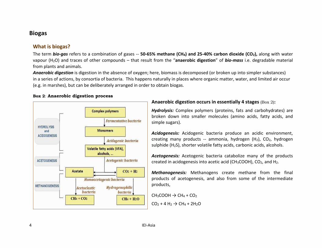
Box 2: Anaerobic digestion process Anaerobic digestion occurs in essentially 4 stages (Box 2):
Hydrolysis: Complex polymers (proteins, fats and carbohydrates) are broken down into smaller molecules (amino acids, fatty acids, and simple sugars).
Acidogenesis: Acidogenic bacteria produce an acidic environment, creating many products -- ammonia, hydrogen (H2), CO2, hydrogen sulphide (H2S), shorter volatile fatty acids, carbonic acids, alcohols.
Acetogenesis: Acetogenic bacteria catabolize many of the products created in acidogenesis into acetic acid (CH3COOH), CO2, and H2.
Methanogenesis: Methanogens create methane from the final products of acetogenesis, and also from some of the intermediate products,
CH3COOH → CH4 + CO2
CO2 + 4 H2 → CH4 + 2H2O
INTRODUCTION
IEI-Asia 5
Advantages of biogas generation in farming regions
Reliable and relatively cheap energy feedstock: Due to their biodegradability and moisture content, bovine and other farm-animal wastes and most crop-residues make suitable “feedstock” for anaerobic digestion. These can be available on farms, throughout the year, and as they depend on regular activities and are not likely to be hampered by procurement problems (such as tenuous fuel agreements), generation is reliable. This energy feedstock does not as yet have much commercial value1, so that collection and transport constitute the main operating costs. So, when generated near farms, biogas is inexpensive.
Useful alternative fuel: The calorific content (heating value) of biogas is between 17 and 24 MJ/m3 (increasing with the proportion of methane), making it suitable for stove-fuel. Other uses in rural regions include powering engines for electricity generation and even absorption refrigerators (that use a flame rather than an electric compressor to create the evaporative cooling cycle).
Replacement of solid biomass burning and its health impacts: The use of solid biomass (e.g. twigs, crop residues) as stove-fuel, particularly without adequate ventilation, causes respiratory problems from inhaling particulates of incomplete combustion and eye-irritation from smoky fires. Over time, more serious ailments such as ischaemic heart disease may also occur. Hence, using biogas as stove-fuel is better for health.
Replacement of the problems of procuring other fuels: Assured supply of biogas could replace solid biomass as stove-fuel. Consequently, the burden of gathering such biomass and related problems (e.g. storage during the rainy seasons) would be avoided. The potential need for liquefied petroleum gas (LPG) and the resulting costs of its production and transportation over long distances (borne by the government through subsidies for domestic supply) would also be reduced.
Better fertilizer: While (vegetative/animal) farm waste is usually accumulated in compost heaps for manure, the effluents from the biogas-generation process are far preferable to such farmyard compost because of their higher nitrogen content per unit, and reduced pathogens and weed seeds.
Environmentally preferable: Burning fossil fuels converts carbon stored for millions of years in the earth’s crust to CO2 that in the atmosphere is a greenhouse gas (GHG) contributing to climate change. While the combustion of biogas (methane) also releases CO2, the carbon in biogas was taken recently from the atmosphere by plants’ photosynthetic activity, so that this carbon cycle is closed in a relatively short time. Further, this CO2 is less than that from other hydro-carbons. In addition, producing biogas in sealed digesters reduces the need for burning and/or open compost heaps – the usual disposal methods for crop waste. This reduces the emissions of not only CO2, but more importantly CH4 and nitrous oxide (N2O), thereby lowering the impact on climate, as the GHG potential of CH4 is 23 times, and that of N2O 296 times, that of CO2.
1 Banana stem fibre could be used for manufacturing fabric and paper, but this has not yet taken off on a large scale.
6 IEI-Asia
Biogas generation for stove-fuel in India
Biogas generation through anaerobic digestion of biomass has been carried out successfully in India and other parts of the world for
decades. The Government of India (GoI) has been promoting the use of biogas for stove-fuel in a concerted manner since the
1970s’, with the All India Coordinated Project on Biogas Technology and Utilisation, of the then Department of Science and
Technology. The National Programme on Biogas Development commenced in 1982.
There have subsequently been several programmes of the Central and State Governments for increasing biogas generation. The
National Biogas and Manure Management Programme of the XIIth Five-Year-Plan (2012-17) is in operation, with subsidies for
construction costs. According to the GoI Ministry for New and Renewable Energy (MNRE), the total biogas generation capacity in
India in March 2015 was 2075.7 million m3. However, current data on functional digesters are not available; a sample survey of 4194
new plants (established during 2007-12) revealed that 4.5% were not in operation, and many older plants have been completely
abandoned.
Biogas plants are sized according to the intended use – most are for a single family each, but there are a few that are shared by
groups of families or even communities.
The first village-scale biogas system was constructed in 1979, in the village of Fateh Singh ka Purva, Uttar Pradesh state. The dung-
fuelled system provided households with biogas for cooking and also powered a dual-fuel engine to generate electricity for lighting.
Soon after, Gram Vikas, an NGO working among deprived communities in Orissa (now Odisha) state, began establishing biogas
plants; at community-plants, a gas-fuelled generator powered electricity generation for lighting. Larger digesters with a total
capacity of 630m3 were constructed in 1988 in Methan, Gujarat state; these were fuelled with dung by farmers of the co-operative
dairy there, for the generation of biogas for cook-stove fuel at hundreds of homes. More recently, the International Energy Initiative
in Bangalore (IEI-Asia) has developed shared waste-to-biogas systems in villages. These are fuelled with cattle-dung or vegetative-
waste. The gas so produced has been used mainly for stove-fuel for small groups of families -- those who had used only solid
biomass and those who were registered LPG users but were unable to obtain an adequate supply. In one case, methane from biogas
was used to power a 100% methane-fuelled engine for generating electricity for a village during peak demand periods.
Note: As this handbook focuses on banana cultivation and the use of its waste for generating biogas for cooking fuel, only these
requirements are being discussed further.

PRE-REQUISITES
IEI-Asia 7
Estimating biogas equivalent of LPG use:
[{(8 cylinders x 14.2kg)/year}
x 45.8 MJ/kg x 64%]LPG
÷ [(17.7 MJ/m3 x 55%)]biogas
= 342 m3/family/year
or 0.937 m3/family/day
≈ 1 m3 of biogas/day
PRE-REQUISITES FOR BANANA-GROWING AND GENERATING BIOGAS FOR STOVE-FUEL Accessing water sustainably
Water retention
Conservative use of water
Substrate for biogas generation
Banana plantation waste
Water
Gas for stove-fuelling
Biogas equivalent of current fuel use
Biogas generation facilities
Banana growing
Supplementary irrigation
Supplementary soil nutrients
Pre-implementation permission
8 IEI-Asia
This Section focuses on the pre-requisites, i.e. the requirements that should be verified before commencement, for banana cultivation and biogas generation (Box 3). Box 3: Pre-commencement checks for natural resources
Accessing water sustainably
Water is essential for most life forms and accessible sources are easily exhaustible. But there are ways, many of which were used traditionally in India, through which water flowing in the region can be harnessed and stored. In recent years, the shortage of water has prompted people to resort to these traditional methods of water “harvesting”. Due to these efforts, even regions considered to be drought-prone have secured water for local needs, including crop cultivation.
Therefore, before undertaking banana cultivation and biogas generation, access to water should be assessed and efforts made for water sources to be retained and/or rejuvenated, and for water to be used conservatively.
Water retention
When planning for a region comprising several villages, measures to prevent the loss of water in the entire “water shed” could be required. The term water shed (or catchment) of a river refers to the region from which water gets directed into the river and its contributing tributaries. Obviously, the water retention structures have to be on a scale corresponding to the targeted region.
Community-/farm-scale water harnessing: As the focus of this handbook is on farmers or groups/communities of farmers, local water harvesting measures are being described.
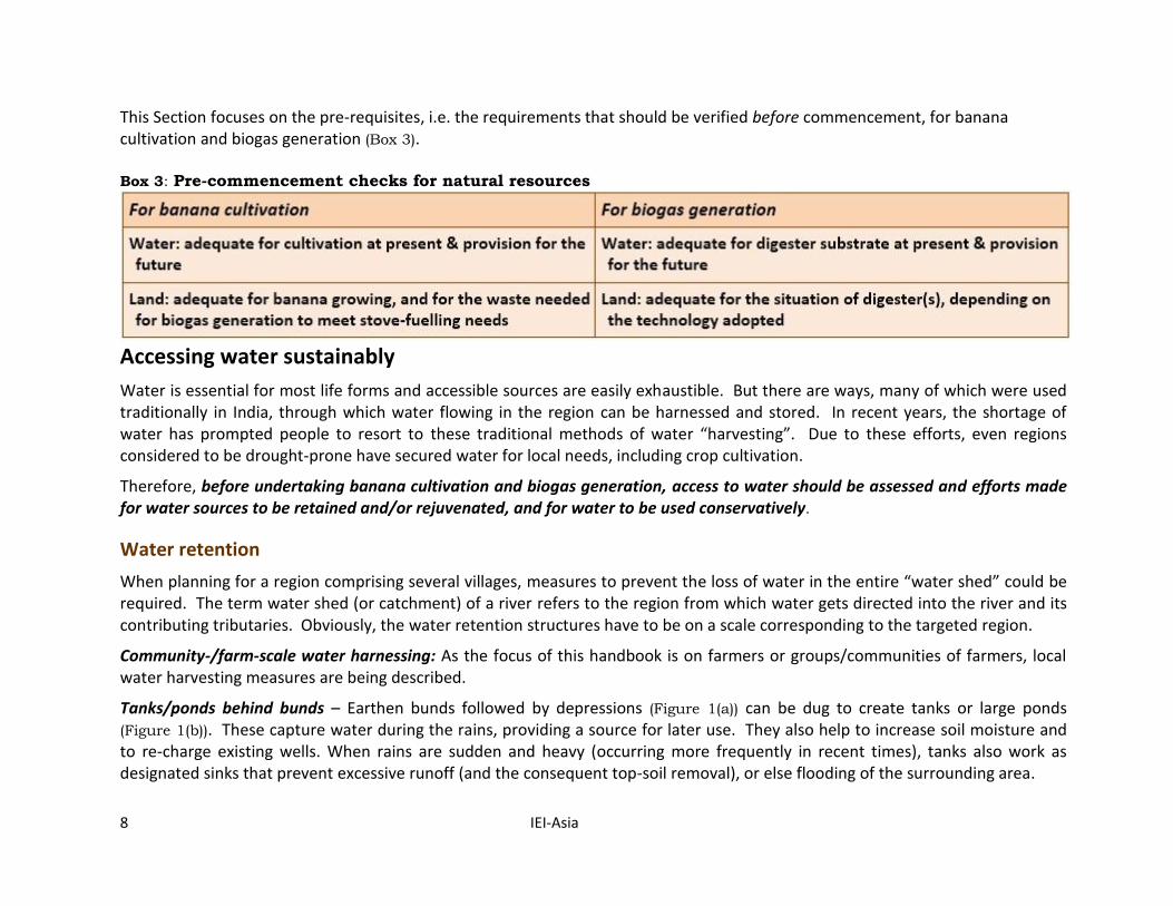
Tanks/ponds behind bunds – Earthen bunds followed by depressions (Figure 1(a)) can be dug to create tanks or large ponds (Figure 1(b)). These capture water during the rains, providing a source for later use. They also help to increase soil moisture and to re-charge existing wells. When rains are sudden and heavy (occurring more frequently in recent times), tanks also work as designated sinks that prevent excessive runoff (and the consequent top-soil removal), or else flooding of the surrounding area.
PRE-REQUISITES
IEI-Asia 9
Figure 1: Farm bunds and ponds - (a) channel to collect water (SPS, 1999) (b) multi-purpose pond (IEI-Asia, 2010)
Additional benefits can be integrated – the basis
of a sustainable model – through the
introduction of fish and edible plants. The
resulting revenue improves livelihood, ensuring
protection of the tanks and thereby water
security.
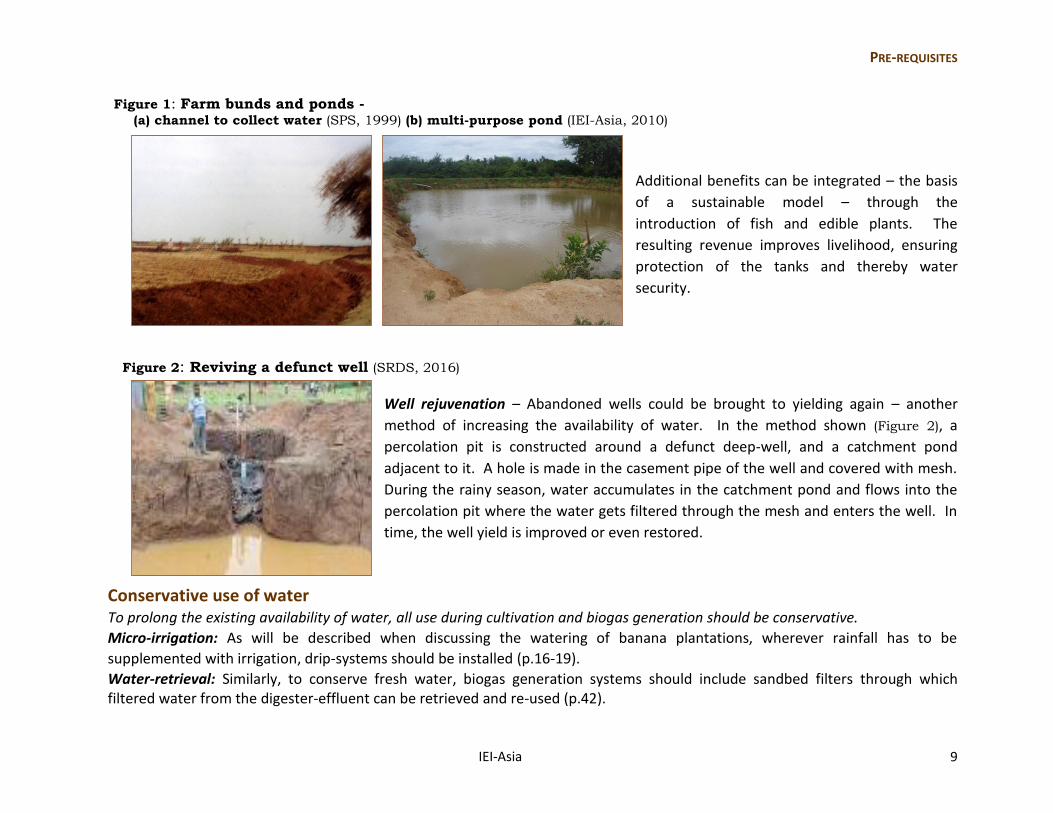
Figure 2: Reviving a defunct well (SRDS, 2016)
Well rejuvenation – Abandoned wells could be brought to yielding again – another
method of increasing the availability of water. In the method shown (Figure 2), a
percolation pit is constructed around a defunct deep-well, and a catchment pond
adjacent to it. A hole is made in the casement pipe of the well and covered with mesh.
During the rainy season, water accumulates in the catchment pond and flows into the
percolation pit where the water gets filtered through the mesh and enters the well. In
time, the well yield is improved or even restored.
Conservative use of water To prolong the existing availability of water, all use during cultivation and biogas generation should be conservative. Micro-irrigation: As will be described when discussing the watering of banana plantations, wherever rainfall has to be
supplemented with irrigation, drip-systems should be installed (p.16-19).
Water-retrieval: Similarly, to conserve fresh water, biogas generation systems should include sandbed filters through which filtered water from the digester-effluent can be retrieved and re-used (p.42).
10 IEI-Asia
Substrate for biogas generation
Organic matter consists chiefly of carbon and (lower amounts of) nitrogen. Organisms require the correct proportion of carbon
for energy and nitrogen for protein production. The balance of these two elements, called the carbon-to-nitrogen ratio (or C : N
ratio) has been scientifically determined, for micro-organisms to effect decomposition, at between 25 and 30 parts carbon to 1
part nitrogen (or 25-30 : 1). Hence, the digester “substrate”, or material to be digested, has to meet these requirements.
Banana plantation waste
Bananas plantations are appropriate for waste-based biogas generation because of the copious biomass produced.
It has been found2 that stem, peel, and fruit fractions represent 0.84%, 17.71%, and 81.46% of the total methane production potential of the whole banana plant, with specific methane yield3 of:
stems: 0.256 m3 per kg total solids (TS); peels: 0.322 m3 per kg TS; fruit: 0.367 m3 per kg TS.
Elsewhere4, stem slurries alone have yielded between 0.267 m3 – 0.271m3 biogas per kg TS. The slurries ranged from 2% to 16%
(total solids to water) concentration, anaerobically digested under “mesophilic” (i.e. 37–40°C) temperature conditions.
(Anaerobic digestion for the production of biogas was explained on p.4).
A conservative assumption for biogas generation from banana stem slurries would therefore be:
≈ 0.250 m3 of biogas per kg TS
=> 1m3 of biogas from ≈ 4 kg chopped stems
Note: Green-waste always produces more gas per unit (weight) than animal dung, while food-waste (with sugars, fats) produces
even more; the efficacy of the biogas plant design is a separate issue.
Although stems are the lowest gas-yielding part of the banana plant, fruit and peels can be used for (human and animal)
nutritional needs, so that the stems are the only “waste” material available.
2 Ref. Argyropoulos et al., 2009. 3 Ref. Clarke et al., 2005. 4 Ref. Kalia et al., 2000.
PRE-REQUISITES
IEI-Asia 11
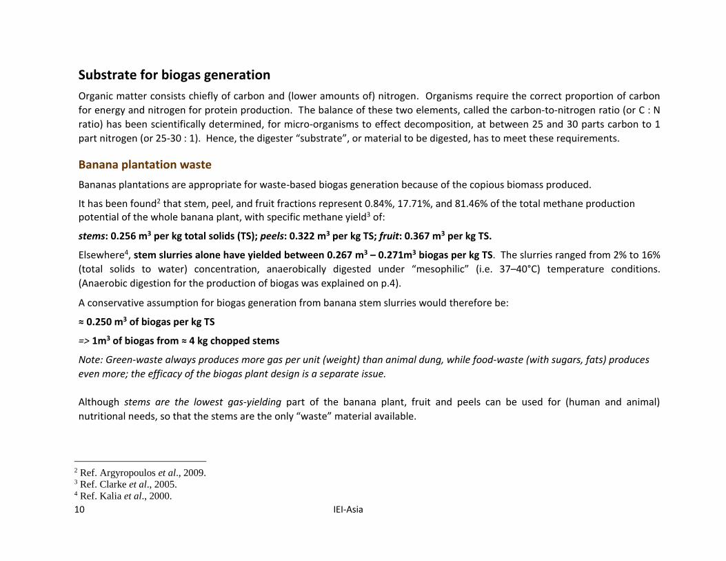
Figure 3: Banana plantation -- numerous pseudo-stems
Moreover, unlike with other plants, many (Figure 3) “pseudo”
stems, consisting of successive thickened leaf-sheaths, grow out of
the real underground stem (rhizome or corm). Most5 of these
stems have to be cut down when less than a meter high in order to
conserve nutrients for the fruit-bearing stalk. Hence, these “waste”
stems can easily be used for generating biogas.
Further, as all the pseudo stems – those surrounding the fruit-
bearing stalk during its growth and that stalk after the harvest -- are
suitable for digester loading, the supply of such material is
available around the year for digester-feedstock.
Depending on the type of banana selected and the corresponding density of plantation, 15 - 18 tonnes per acre of stem-waste
are available annually. Hence, considering only these stems (or leaf-sheaths) for biogas production is feasible.
Note: Pseudo-stems do not grow abundantly at new plantations and as the fruit-bearing pseudo-stem is cut only at harvesting (10-
12 months after planting), the construction of biogas-digesters can be commenced after the plantations. In contrast, digesters for
cattle waste have to be completed before the livestock are brought in, to enable immediate insertion of the dung.
Water
Biogas production has been carried out with a range of stem-water slurry input, from 2% to 16% TS, i.e. between (2 kg of chopped stems with 98 litres of water) and (16 kg of stems with 84 litres of water).
Recent demonstrations (IEI-Asia, 2014; 2016) have worked with between 7.7% and 10% TS slurries,
i.e. 1 kg of chopped banana stems has to be mixed with 9 - 12 litres (or kg) of water
=> 1m3 biogas requires ≈ 4 kg of chopped stems + 36 - 48 litres of water
However, this biogas-production requirement does not have to be met with fresh water: filtering of the digester-effluent sludge
(ref. p.42) and even the condensed moisture (ref. p.48) from the digesters enable some water recovery.
5 One may be kept for the following crop, if desired, unless only tissue-cultured saplings are used.
12 IEI-Asia
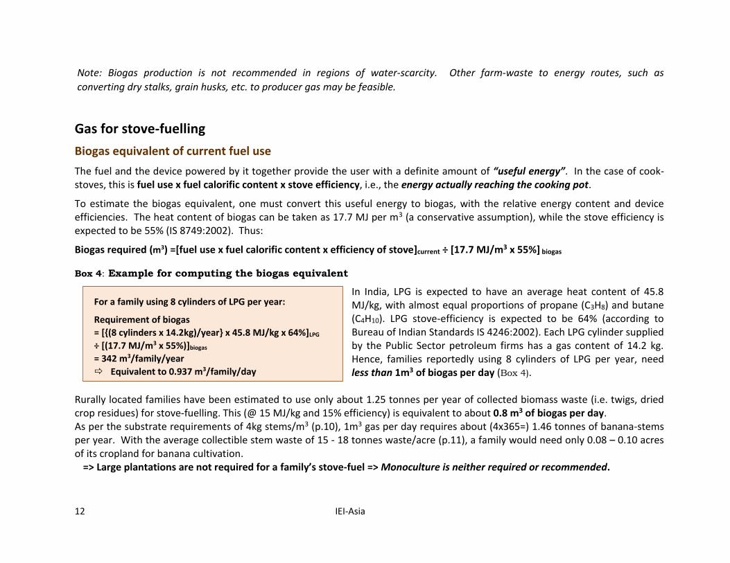
For a family using 8 cylinders of LPG per year:
Requirement of biogas
= [{(8 cylinders x 14.2kg)/year} x 45.8 MJ/kg x 64%]LPG
÷ [(17.7 MJ/m3 x 55%)]biogas
= 342 m3/family/year
Equivalent to 0.937 m3/family/day
Note: Biogas production is not recommended in regions of water-scarcity. Other farm-waste to energy routes, such as
converting dry stalks, grain husks, etc. to producer gas may be feasible.
Gas for stove-fuelling
Biogas equivalent of current fuel use
The fuel and the device powered by it together provide the user with a definite amount of “useful energy”. In the case of cook-stoves, this is fuel use x fuel calorific content x stove efficiency, i.e., the energy actually reaching the cooking pot.
To estimate the biogas equivalent, one must convert this useful energy to biogas, with the relative energy content and device efficiencies. The heat content of biogas can be taken as 17.7 MJ per m3 (a conservative assumption), while the stove efficiency is expected to be 55% (IS 8749:2002). Thus:
Biogas required (m3) =[fuel use x fuel calorific content x efficiency of stove]current ÷ [17.7 MJ/m3 x 55%] biogas
Box 4: Example for computing the biogas equivalent
In India, LPG is expected to have an average heat content of 45.8 MJ/kg, with almost equal proportions of propane (C3H8) and butane (C4H10). LPG stove-efficiency is expected to be 64% (according to Bureau of Indian Standards IS 4246:2002). Each LPG cylinder supplied by the Public Sector petroleum firms has a gas content of 14.2 kg. Hence, families reportedly using 8 cylinders of LPG per year, need less than 1m3 of biogas per day (Box 4).
Rurally located families have been estimated to use only about 1.25 tonnes per year of collected biomass waste (i.e. twigs, dried crop residues) for stove-fuelling. This (@ 15 MJ/kg and 15% efficiency) is equivalent to about 0.8 m3 of biogas per day. As per the substrate requirements of 4kg stems/m3 (p.10), 1m3 gas per day requires about (4x365=) 1.46 tonnes of banana-stems per year. With the average collectible stem waste of 15 - 18 tonnes waste/acre (p.11), a family would need only 0.08 – 0.10 acres of its cropland for banana cultivation.
=> Large plantations are not required for a family’s stove-fuel => Monoculture is neither required or recommended.
PRE-REQUISITES
IEI-Asia 13
Note: While other organic waste material (crop-residues, animal waste, over-ripe fruit/vegetables, peels) with a farm household
may not be enough for generating adequate gas for all stove-fuelling needs, it can be added to the digesters to increase gas
production if there is no other use for such material.
Biogas generation facilities
Once the daily gas requirement has been estimated, the volume of the gas generation facility can be planned according to the volumetric ratio i.e. gas produced per unit volume of the digester, of the generation plant selected. There are several types of biogas generating plants currently in operation: these range in complexity from modified plastic containers to those requiring masonry/concrete construction, and in terms of space required, from water-tanks placed one above the other, to digesters with additional input/output tanks and sand-beds (ref. pp.26-30). Accordingly, factors determining the choice of plant include costs, the access to construction expertise, and the availability of land that can be allocated for the plant.
Banana growing
Many varieties of banana (genus Musa) are grown in India and elsewhere in the world. These grow best in the 25ºC – 35ºC range,
but such temperatures are not limiting conditions in India. However, the need for supplementary irrigation and soil nutrients
could be constraints.
Supplementary irrigation
Banana plants need regular watering, particularly once they start efflorescing. This usually necessitates supplementary
irrigation. As less than 50% of the net area sown in India currently has access to irrigation, investment in irrigation facilities would
be required.
Further, bananas require moist but well-drained soil, as the underground stem can be injured by over-watering or through water
stagnation due to inadequate drainage. Hence, micro-irrigation through drip systems is recommended.
Indian farmers get access to irrigation from two sources: surface water (i.e. water channelled from surface flows or storage
reservoirs) and groundwater (i.e. water extracted from underground aquifers through wells).
Surface water irrigation is obtained mainly through dams and the corresponding canal networks (largely gravity-fed), as well as
river lift irrigation schemes (requiring power). As these are provided by the state to specific regions, those farms within their
14 IEI-Asia
command area can get access, except at the tail-ends where supply may be inadequate. However, with individual effort,
irrigation can be carried out with farm tanks and ponds (already discussed on pp.8-9).
Groundwater can be accessed through dug or drilled (deep) wells. Correspondingly, water can be obtained manually via tube-wells, or with electrically- or diesel-powered pumps. Groundwater is now the most accessed source, contributing to over 60% of the irrigated area of the country, and almost all irrigation in the Deccan plateau. This has already resulted in over-exploitation (i.e. extraction exceeding recharge rates) 6 in some regions.
Supplementary soil nutrients
Preferred soils are loamy and neither acidic nor alkaline (pH of 6.5 – 7.5). The high nitrogen (N), potash (K) and phosphorus (P)
requirement usually necessitates additional manure/fertilizers, to improve the soil’s nutrient content and to compensate for the
nutrients withdrawn from the soil by successive crops.
Pre-implementation permission
The use of groundwater does not have to be paid for and the use of electricity from (state-sponsored) utilities for pumping out water for agricultural needs (with pumps of less than 10HP) is also free or highly subsidised in most states of India. But permission has to be sought from the concerned authorities before accessing these amenities.
Groundwater extraction: To restrict the indiscriminate use of groundwater, some states – particularly in the plateau region of peninsular India - have introduced regulations7 regarding the drilling of deep wells. For example, in Karnataka, to drill deep wells legally, permission has to be sought from the local (taluk or county level) Revenue Secretary. Once permission is granted, a “right to water” certificate is provided; on this basis, a drilling rig can be hired for groundwater extraction on the farm (although the exact location of the drilling can be selected by the farmers).
Electrically-operated pumps: Legal extraction of water with pumps powered by the regional electricity distribution companies also requires prior permission. In Karnataka, inspection by an Assistant Engineer of the relevant zone is needed and a fixed charge per unit of connected load (per HP per month) is levied, although the energy use (kWh) does not have to be paid for.
6 Groundwater usability, defined as annual groundwater draft ÷ net annual groundwater availability, is classified as safe (≤ 70%), “semi-critical”
or “grey” (70 – 90%), “critical” or “dark” (90-100%), and “over-exploited” (over 100%, i.e. where annual groundwater draft exceeds the long-
term rate of annual recharge). Of the 5,723 administrative units in the country that were assessed by the Central Ground Water Board, in 550,
groundwater resources were found semi-critical, 226 were critical, and 839 were found to be over-exploited (CGWB-MoWR, 2006). 7 For example, the Andhra Pradesh Water, Land, and Trees Act (APWALTA), 2002, the Karnataka Groundwater (Regulation and Control) Act,
2002, the Tamil Nadu Groundwater Development and Management Act, 2003.
BANANA CULTIVATION
IEI-Asia 15
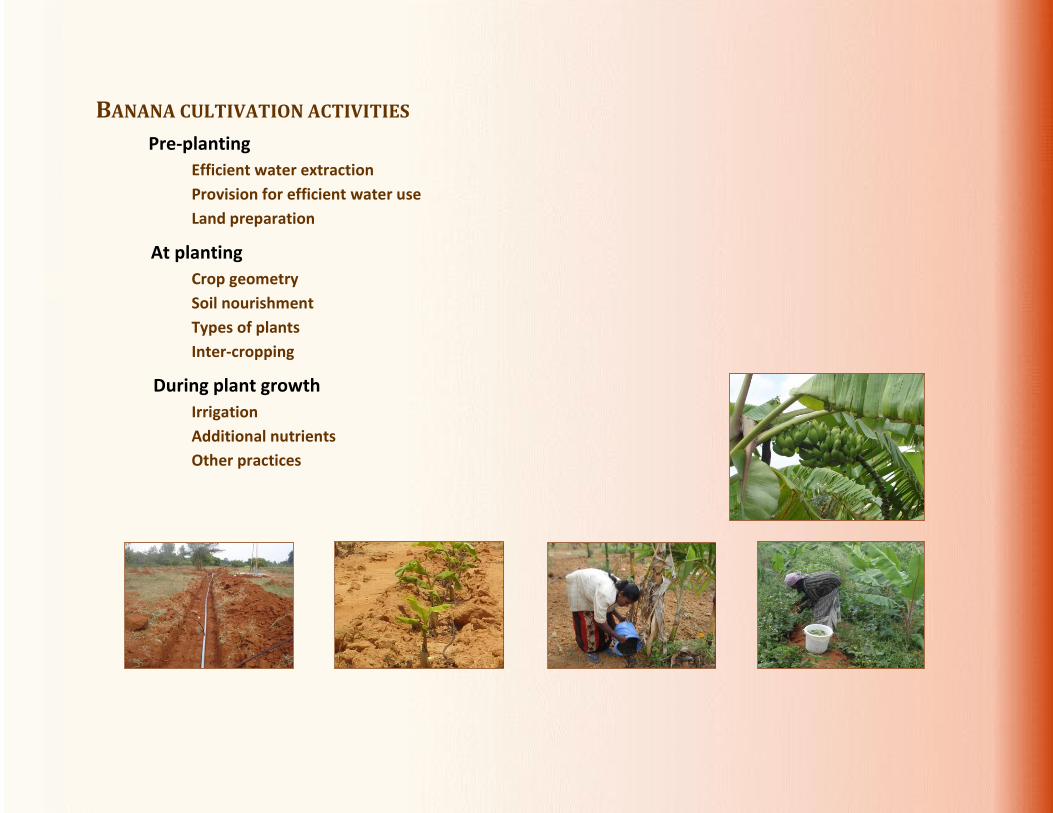
BANANA CULTIVATION ACTIVITIES
Pre-planting
Efficient water extraction
Provision for efficient water use
Land preparation
At planting
Crop geometry
Soil nourishment
Types of plants
Inter-cropping
During plant growth
Irrigation
Additional nutrients
Other practices
16 IEI-Asia
Pre-planting As the development of banana plantations takes about 15 months, from pre-planting activities to the first harvest, while the construction of masonry biogas plants usually takes between 2 and 6 months (depending on the size and location), the plantation activities should be commenced first.
Efficient water-extraction
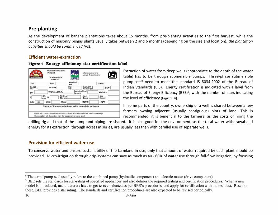
Figure 4: Energy-efficiency star certification label
Extraction of water from deep wells (appropriate to the depth of the water
table) has to be through submersible pumps. Three-phase submersible
pump-sets8 need to meet the standard IS 8034:2002 of the Bureau of
Indian Standards (BIS). Energy certification is indicated with a label from
the Bureau of Energy Efficiency (BEE)9, with the number of stars indicating
the level of efficiency (Figure 4).
In some parts of the country, ownership of a well is shared between a few
farmers owning adjacent (usually contiguous) plots of land. This is
recommended: it is beneficial to the farmers, as the costs of hiring the
drilling rig and that of the pump and piping are shared. It is also good for the environment, as the total water withdrawal and
energy for its extraction, through access in series, are usually less than with parallel use of separate wells.
Provision for efficient water-use
To conserve water and ensure sustainability of the farmland in use, only that amount of water required by each plant should be
provided. Micro-irrigation through drip-systems can save as much as 40 - 60% of water use through full-flow irrigation, by focusing
8 The term “pump-set” usually refers to the combined pump (hydraulic component) and electric motor (drive component). 9 BEE sets the standards for star-rating of specified appliances and also defines the required testing and certification procedures. When a new
model is introduced, manufacturers have to get tests conducted as per BEE’s procedures, and apply for certification with the test data. Based on
these, BEE provides a star rating. The standards and certification procedures are also expected to be revised periodically.
BANANA CULTIVATION
IEI-Asia 17
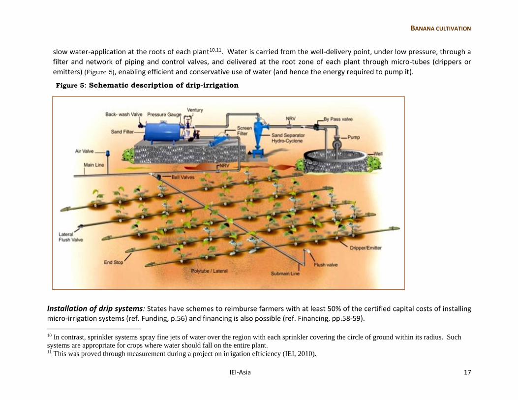
slow water-application at the roots of each plant10,11. Water is carried from the well-delivery point, under low pressure, through a
filter and network of piping and control valves, and delivered at the root zone of each plant through micro-tubes (drippers or
emitters) (Figure 5), enabling efficient and conservative use of water (and hence the energy required to pump it).
Figure 5: Schematic description of drip-irrigation
Installation of drip systems: States have schemes to reimburse farmers with at least 50% of the certified capital costs of installing micro-irrigation systems (ref. Funding, p.56) and financing is also possible (ref. Financing, pp.58-59).
10 In contrast, sprinkler systems spray fine jets of water over the region with each sprinkler covering the circle of ground within its radius. Such
systems are appropriate for crops where water should fall on the entire plant. 11 This was proved through measurement during a project on irrigation efficiency (IEI, 2010).
18 IEI-Asia
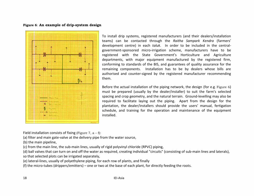
Figure 6: An example of drip-system design
To install drip systems, registered manufacturers (and their dealers/installation teams) can be contacted through the Raitha Sampark Kendra (farmers’ development centre) in each taluk. In order to be included in the central-government-sponsored micro-irrigation scheme, manufacturers have to be registered with the State Government’s Horticulture and Agriculture departments, with major equipment manufactured by the registered firm, conforming to standards of the BIS, and guarantees of quality assurance for the remaining components. Installation has to be by dealers whose bills are authorised and counter-signed by the registered manufacturer recommending them.
Before the actual installation of the piping network, the design (for e.g. Figure 6) must be prepared (usually by the dealer/installer) to suit the farm’s selected spacing and crop geometry, and the natural terrain. Ground-levelling may also be required to facilitate laying out the piping. Apart from the design for the plantation, the dealer/installers should provide the users’ manual, fertigation schedule, and training for the operation and maintenance of the equipment installed.
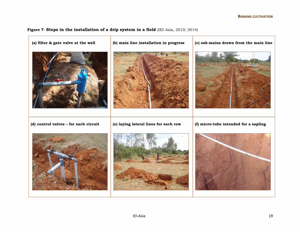
Field installation consists of fixing (Figure 7, a – f): (a) filter and main gate-valve at the delivery pipe from the water source, (b) the main pipeline, (c) from the main line, the sub-main lines, usually of rigid polyvinyl chloride (RPVC) piping, (d) ball valves that can turn on and off the water as required, creating individual "circuits" (consisting of sub-main lines and laterals), so that selected plots can be irrigated separately, (e) lateral-lines, usually of polyethylene piping, for each row of plants, and finally (f) the micro-tubes (drippers/emitters) – one or two at the base of each plant, for directly feeding the roots.
BANANA CULTIVATION
IEI-Asia 19
Figure 7: Steps in the installation of a drip system in a field (IEI-Asia, 2010; 2014)
(a) filter & gate valve at the well
(b) main line installation in progress
(c) sub-mains drawn from the main line
(d) control valves – for each circuit
(e) laying lateral lines for each row
(f) micro-tube intended for a sapling
20 IEI-Asia
Land preparation
The banana plants’ need for nutrients and aerated soils necessitates various efforts to improve the soil.
If planned at least 3 months in advance of planting saplings, leguminous (fabacae leguminosae) crops -- cowpeas or black-eyed
peas (Vigna unguiculata), and chickpeas or gram peas (Cicer arietinum), could be grown. This facilitates nitrogen-fixing.
Soil-raking (with rotovators, bullock-drawn ploughs, or even manually) is essential for aeration.
The planting spots that are dug should be left open for some days (for solar radiation), and then refilled with top-soil mixed with
green manure (for soil nourishment and also to reduce salinity, if any).
To protect the roots from ants and termites, preparations from neem (Azadirachta indica) or alternative plant-based insect-
repellents are recommended.
At planting
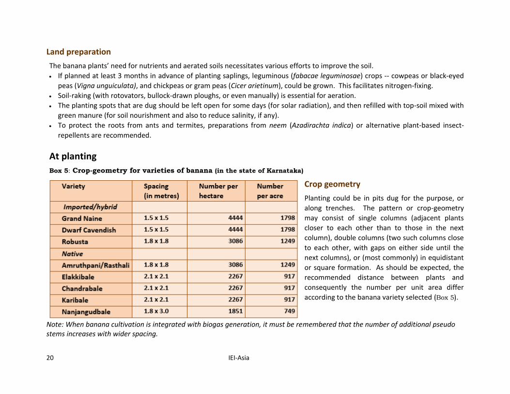
Box 5: Crop-geometry for varieties of banana (in the state of Karnataka)
Crop geometry
Planting could be in pits dug for the purpose, or
along trenches. The pattern or crop-geometry
may consist of single columns (adjacent plants
closer to each other than to those in the next
column), double columns (two such columns close
to each other, with gaps on either side until the
next columns), or (most commonly) in equidistant
or square formation. As should be expected, the
recommended distance between plants and
consequently the number per unit area differ
according to the banana variety selected (Box 5).
Note: When banana cultivation is integrated with biogas generation, it must be remembered that the number of additional pseudo stems increases with wider spacing.
BANANA CULTIVATION
IEI-Asia 21
Soil nourishment
At the outset, additional nutrients are required. Hence, while planting each sapling, some green manure (composted leaf litter, crop residues, dung) and cattle-dung (or, in subsequent years, biogas-digester effluents) should be added to the pit.
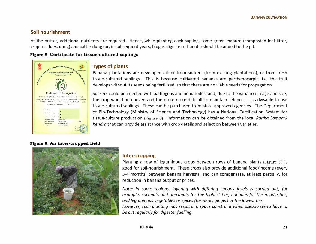
Figure 8: Certificate for tissue-cultured saplings
Types of plants
Banana plantations are developed either from suckers (from existing plantations), or from fresh
tissue-cultured saplings. This is because cultivated bananas are parthenocarpic, i.e. the fruit
develops without its seeds being fertilized, so that there are no viable seeds for propagation.
Suckers could be infected with pathogens and nematodes, and, due to the variation in age and size,
the crop would be uneven and therefore more difficult to maintain. Hence, it is advisable to use
tissue-cultured saplings. These can be purchased from state-approved agencies. The Department
of Bio-Technology (Ministry of Science and Technology) has a National Certification System for
tissue-culture production (Figure 8). Information can be obtained from the local Raitha Sampark
Kendra that can provide assistance with crop details and selection between varieties.
Figure 9: An inter-cropped field
Inter-cropping Planting a row of leguminous crops between rows of banana plants (Figure 9) is
good for soil-nourishment. These crops also provide additional food/income (every
3-4 months) between banana harvests, and can compensate, at least partially, for
reduction in banana output or prices.
Note: In some regions, layering with differing canopy levels is carried out, for example, coconuts and arecanuts for the highest tier, bananas for the middle tier, and leguminous vegetables or spices (turmeric, ginger) at the lowest tier. However, such planting may result in a space constraint when pseudo stems have to be cut regularly for digester fuelling.
22 IEI-Asia
During plant growth
While farming communities are accustomed to cultivation, the following suggestions -- associated with energy-efficiency, resource-conservation, and environmental protection -- could be considered.
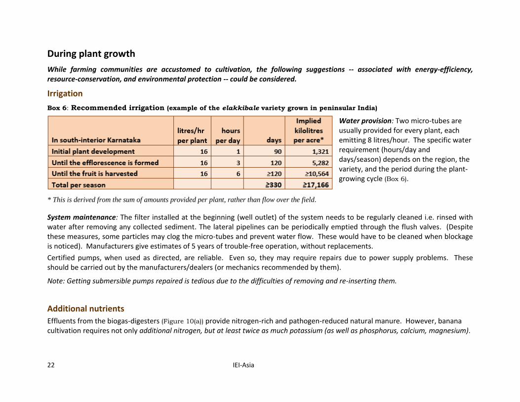
Irrigation
Box 6: Recommended irrigation (example of the elakkibale variety grown in peninsular India)
Water provision: Two micro-tubes are usually provided for every plant, each emitting 8 litres/hour. The specific water requirement (hours/day and days/season) depends on the region, the variety, and the period during the plant-growing cycle (Box 6).
* This is derived from the sum of amounts provided per plant, rather than flow over the field.
System maintenance: The filter installed at the beginning (well outlet) of the system needs to be regularly cleaned i.e. rinsed with water after removing any collected sediment. The lateral pipelines can be periodically emptied through the flush valves. (Despite these measures, some particles may clog the micro-tubes and prevent water flow. These would have to be cleaned when blockage is noticed). Manufacturers give estimates of 5 years of trouble-free operation, without replacements.
Certified pumps, when used as directed, are reliable. Even so, they may require repairs due to power supply problems. These should be carried out by the manufacturers/dealers (or mechanics recommended by them).
Note: Getting submersible pumps repaired is tedious due to the difficulties of removing and re-inserting them.
Additional nutrients
Effluents from the biogas-digesters (Figure 10(a)) provide nitrogen-rich and pathogen-reduced natural manure. However, banana cultivation requires not only additional nitrogen, but at least twice as much potassium (as well as phosphorus, calcium, magnesium).
BANANA CULTIVATION
IEI-Asia 23
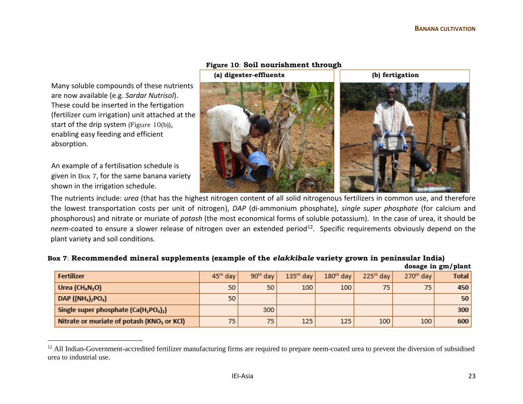
Figure 10: Soil nourishment through
(a) digester-effluents (b) fertigation
Many soluble compounds of these nutrients are now available (e.g. Sardar Nutrisol). These could be inserted in the fertigation (fertilizer cum irrigation) unit attached at the start of the drip system (Figure 10(b)), enabling easy feeding and efficient absorption.
An example of a fertilisation schedule is
given in Box 7, for the same banana variety
shown in the irrigation schedule.
The nutrients include: urea (that has the highest nitrogen content of all solid nitrogenous fertilizers in common use, and therefore
the lowest transportation costs per unit of nitrogen), DAP (di-ammonium phosphate), single super phosphate (for calcium and
phosphorous) and nitrate or muriate of potash (the most economical forms of soluble potassium). In the case of urea, it should be
neem-coated to ensure a slower release of nitrogen over an extended period12. Specific requirements obviously depend on the
plant variety and soil conditions.
Box 7: Recommended mineral supplements (example of the elakkibale variety grown in peninsular India) dosage in gm/plant
12 All Indian-Government-accredited fertilizer manufacturing firms are required to prepare neem-coated urea to prevent the diversion of subsidised
urea to industrial use.
24 IEI-Asia
Other practices
Weed removal: Manual weeding has to be carried out periodically, so that no chemical “weedicides” need to be used. The growth of an inter-crop also reduces the emergence of weeds.
Plant protection from insects and fungi: Preparations from neem are useful not only at planting but also during plant growth. Pastes made from crushed neem oil and neem leaves boiled in water could be used at the roots of plants to discourage insects and mites as well as fungal growth. A diluted version of the crushed neem leaf extract can be sprayed on the leaves of the plants. This natural treatment does not kill insects/fungi, but prevents their growth and reproduction.
Pruning: As new banana leaves grow from within the plant, the outer leaves get dry. It is preferable to remove these to prevent their harbouring pests. When biogas is being generated, additional pseudo stems have to be cut regularly for digester-substrate.
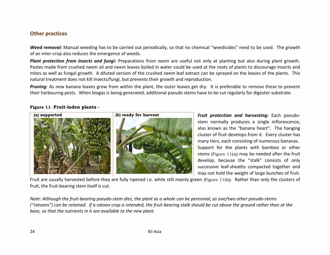
Figure 11: Fruit-laden plants -
Fruit protection and harvesting: Each pseudo-
stem normally produces a single inflorescence,
also known as the "banana heart". The hanging
cluster of fruit develops from it. Every cluster has
many tiers, each consisting of numerous bananas.
Support for the plants with bamboo or other
stems (Figure 11(a)) may be needed after the fruit
develop, because the “stalk” consists of only
successive leaf-sheaths compacted together and
may not hold the weight of large bunches of fruit.
Fruit are usually harvested before they are fully ripened i.e. while still mainly green (Figure 11(b)). Rather than only the clusters of
fruit, the fruit-bearing stem itself is cut.
Note: Although the fruit-bearing pseudo-stem dies, the plant as a whole can be perennial, as one/two other pseudo-stems (“ratoons”) can be retained. If a ratoon crop is intended, the fruit-bearing stalk should be cut above the ground rather than at the base, so that the nutrients in it are available to the new plant.
(a) supported (b) ready for harvest
BIOGAS GENERATION
IEI-Asia 25
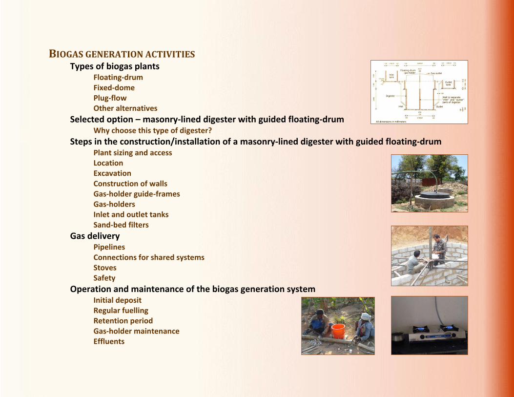
BIOGAS GENERATION ACTIVITIES Types of biogas plants
Floating-drum Fixed-dome Plug-flow Other alternatives
Selected option – masonry-lined digester with guided floating-drum Why choose this type of digester?
Steps in the construction/installation of a masonry-lined digester with guided floating-drum Plant sizing and access Location Excavation Construction of walls Gas-holder guide-frames Gas-holders Inlet and outlet tanks Sand-bed filters
Gas delivery Pipelines Connections for shared systems Stoves Safety
Operation and maintenance of the biogas generation system Initial deposit Regular fuelling Retention period Gas-holder maintenance Effluents
26 IEI-Asia
Types of biogas plants Biogas-generating plants can be classified according to the loading pattern -- either continuous- or batch-fed. At the continuous (or more correctly, semi-continuous) type of plant, input for digestion (i.e. substrate) is regularly fed, with the spent effluents being pushed out as new input accumulates in the digester; hence, gas can be produced without interruption. In contrast, batch-fed digesters are loaded periodically with “batches” of substrate; only when digestion of a particular insertion has been completed is the effluent removed and the process repeated. There could thus be gaps in gas production.
For the purpose of regular stove-fuelling, continuous-fed plants likely to have long usability are being described. These are: masonry digesters with a floating-drum (movable tank), or a fixed-dome gas-holder, or else a plug-flow digester-cum-gasholder.
Floating-drum
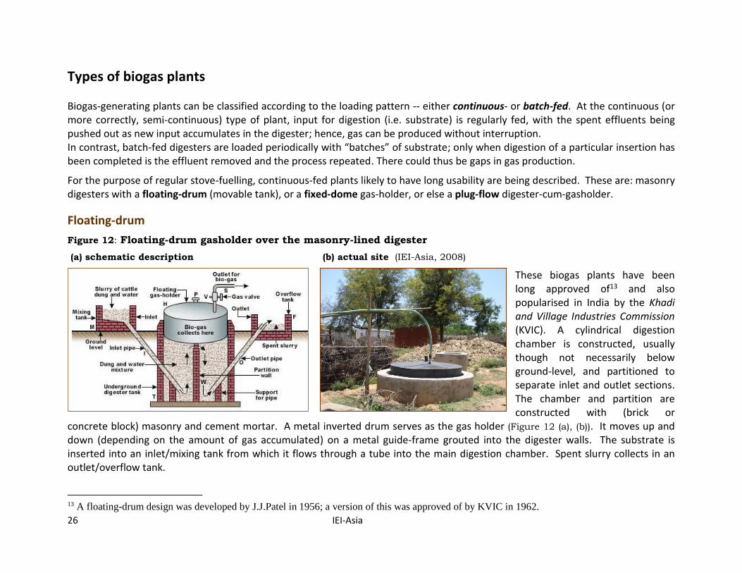
Figure 12: Floating-drum gasholder over the masonry-lined digester
(a) schematic description (b) actual site (IEI-Asia, 2008)
These biogas plants have been long approved of13 and also popularised in India by the Khadi and Village Industries Commission (KVIC). A cylindrical digestion chamber is constructed, usually though not necessarily below ground-level, and partitioned to separate inlet and outlet sections. The chamber and partition are constructed with (brick or
concrete block) masonry and cement mortar. A metal inverted drum serves as the gas holder (Figure 12 (a), (b)). It moves up and down (depending on the amount of gas accumulated) on a metal guide-frame grouted into the digester walls. The substrate is inserted into an inlet/mixing tank from which it flows through a tube into the main digestion chamber. Spent slurry collects in an outlet/overflow tank.
13 A floating-drum design was developed by J.J.Patel in 1956; a version of this was approved of by KVIC in 1962.
BIOGAS GENERATION
IEI-Asia 27
Fixed-dome
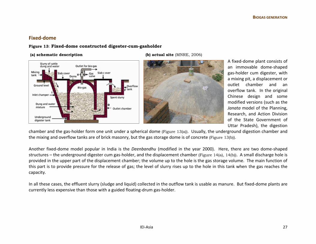
Figure 13: Fixed-dome constructed digester-cum-gasholder
(a) schematic description (b) actual site (MNRE, 2006)
A fixed-dome plant consists of an immovable dome-shaped gas-holder cum digester, with a mixing pit, a displacement or outlet chamber and an overflow tank. In the original Chinese design and some modified versions (such as the Janata model of the Planning, Research, and Action Division of the State Government of Uttar Pradesh), the digestion
chamber and the gas-holder form one unit under a spherical dome (Figure 13(a)). Usually, the underground digestion chamber and the mixing and overflow tanks are of brick masonry, but the gas storage dome is of concrete (Figure 13(b)). Another fixed-dome model popular in India is the Deenbandhu (modified in the year 2000). Here, there are two dome-shaped structures – the underground digester cum gas-holder, and the displacement chamber (Figure 14(a), 14(b)). A small discharge hole is provided in the upper part of the displacement chamber; the volume up to the hole is the gas storage volume. The main function of this part is to provide pressure for the release of gas; the level of slurry rises up to the hole in this tank when the gas reaches the capacity. In all these cases, the effluent slurry (sludge and liquid) collected in the outflow tank is usable as manure. But fixed-dome plants are currently less expensive than those with a guided floating-drum gas-holder.
28 IEI-Asia
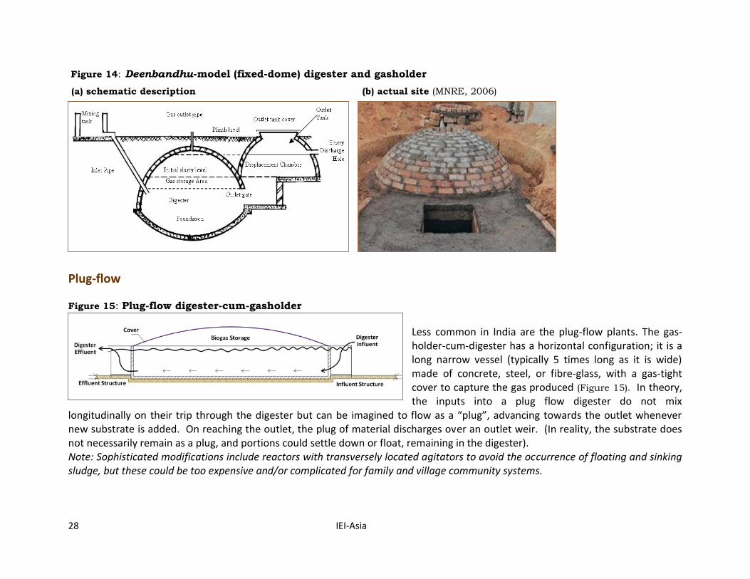
Figure 14: Deenbandhu-model (fixed-dome) digester and gasholder
(a) schematic description (b) actual site (MNRE, 2006)
Plug-flow
Figure 15: Plug-flow digester-cum-gasholder
Less common in India are the plug-flow plants. The gas-holder-cum-digester has a horizontal configuration; it is a long narrow vessel (typically 5 times long as it is wide) made of concrete, steel, or fibre-glass, with a gas-tight cover to capture the gas produced (Figure 15). In theory, the inputs into a plug flow digester do not mix
longitudinally on their trip through the digester but can be imagined to flow as a “plug”, advancing towards the outlet whenever new substrate is added. On reaching the outlet, the plug of material discharges over an outlet weir. (In reality, the substrate does not necessarily remain as a plug, and portions could settle down or float, remaining in the digester). Note: Sophisticated modifications include reactors with transversely located agitators to avoid the occurrence of floating and sinking sludge, but these could be too expensive and/or complicated for family and village community systems.
BIOGAS GENERATION
IEI-Asia 29
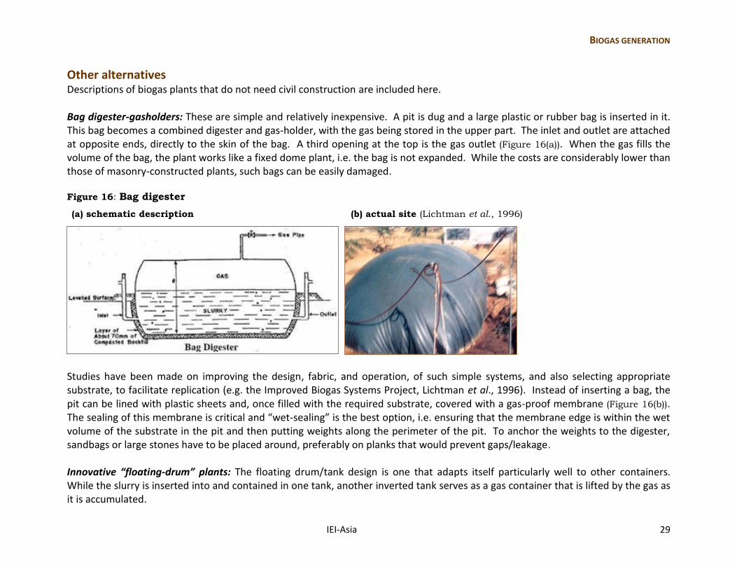
Other alternatives Descriptions of biogas plants that do not need civil construction are included here. Bag digester-gasholders: These are simple and relatively inexpensive. A pit is dug and a large plastic or rubber bag is inserted in it. This bag becomes a combined digester and gas-holder, with the gas being stored in the upper part. The inlet and outlet are attached at opposite ends, directly to the skin of the bag. A third opening at the top is the gas outlet (Figure 16(a)). When the gas fills the volume of the bag, the plant works like a fixed dome plant, i.e. the bag is not expanded. While the costs are considerably lower than those of masonry-constructed plants, such bags can be easily damaged. Figure 16: Bag digester
(a) schematic description (b) actual site (Lichtman et al., 1996)
Studies have been made on improving the design, fabric, and operation, of such simple systems, and also selecting appropriate substrate, to facilitate replication (e.g. the Improved Biogas Systems Project, Lichtman et al., 1996). Instead of inserting a bag, the pit can be lined with plastic sheets and, once filled with the required substrate, covered with a gas-proof membrane (Figure 16(b)). The sealing of this membrane is critical and “wet-sealing” is the best option, i.e. ensuring that the membrane edge is within the wet volume of the substrate in the pit and then putting weights along the perimeter of the pit. To anchor the weights to the digester, sandbags or large stones have to be placed around, preferably on planks that would prevent gaps/leakage. Innovative “floating-drum” plants: The floating drum/tank design is one that adapts itself particularly well to other containers. While the slurry is inserted into and contained in one tank, another inverted tank serves as a gas container that is lifted by the gas as it is accumulated.
30 IEI-Asia
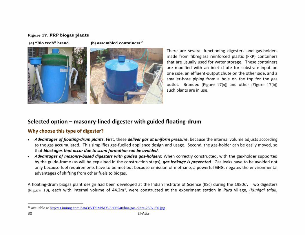
Figure 17: FRP biogas plants
(a) “Bio tech” brand (b) assembled containers14
There are several functioning digesters and gas-holders made from fibreglass reinforced plastic (FRP) containers that are usually used for water storage. These containers are modified with an inlet chute for substrate-input on one side, an effluent-output chute on the other side, and a smaller-bore piping from a hole on the top for the gas outlet. Branded (Figure 17(a)) and other (Figure 17(b)) such plants are in use.
Selected option – masonry-lined digester with guided floating-drum
Why choose this type of digester?
Advantages of floating-drum plants: First, these deliver gas at uniform pressure, because the internal volume adjusts according to the gas accumulated. This simplifies gas-fuelled appliance design and usage. Second, the gas-holder can be easily moved, so that blockages that occur due to scum formation can be avoided.
Advantages of masonry-based digesters with guided gas-holders: When correctly constructed, with the gas-holder supported by the guide-frame (as will be explained in the construction steps), gas leakage is prevented. Gas leaks have to be avoided not only because fuel requirements have to be met but because emission of methane, a powerful GHG, negates the environmental advantages of shifting from other fuels to biogas.
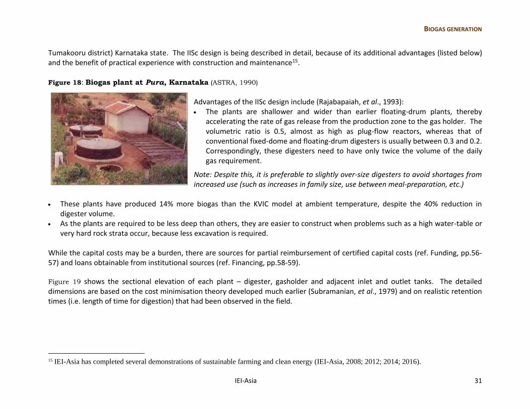
A floating-drum biogas plant design had been developed at the Indian Institute of Science (IISc) during the 1980s’. Two digesters (Figure 18), each with internal volume of 44.2m3, were constructed at the experiment station in Pura village, (Kunigal taluk,
14 available at http://3.imimg.com/data3/VF/JM/MY-3306540/bio-gas-plant-250x250.jpg
BIOGAS GENERATION
IEI-Asia 31
Tumakooru district) Karnataka state. The IISc design is being described in detail, because of its additional advantages (listed below) and the benefit of practical experience with construction and maintenance15. Figure 18: Biogas plant at Pura, Karnataka (ASTRA, 1990)
Advantages of the IISc design include (Rajabapaiah, et al., 1993): The plants are shallower and wider than earlier floating-drum plants, thereby
accelerating the rate of gas release from the production zone to the gas holder. The volumetric ratio is 0.5, almost as high as plug-flow reactors, whereas that of conventional fixed-dome and floating-drum digesters is usually between 0.3 and 0.2. Correspondingly, these digesters need to have only twice the volume of the daily gas requirement.
Note: Despite this, it is preferable to slightly over-size digesters to avoid shortages from increased use (such as increases in family size, use between meal-preparation, etc.)
These plants have produced 14% more biogas than the KVIC model at ambient temperature, despite the 40% reduction in
digester volume. As the plants are required to be less deep than others, they are easier to construct when problems such as a high water-table or
very hard rock strata occur, because less excavation is required. While the capital costs may be a burden, there are sources for partial reimbursement of certified capital costs (ref. Funding, pp.56-57) and loans obtainable from institutional sources (ref. Financing, pp.58-59).
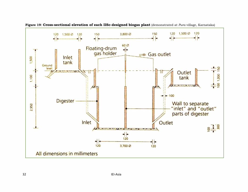
Figure 19 shows the sectional elevation of each plant – digester, gasholder and adjacent inlet and outlet tanks. The detailed dimensions are based on the cost minimisation theory developed much earlier (Subramanian, et al., 1979) and on realistic retention times (i.e. length of time for digestion) that had been observed in the field.
15 IEI-Asia has completed several demonstrations of sustainable farming and clean energy (IEI-Asia, 2008; 2012; 2014; 2016).
32 IEI-Asia
Figure 19: Cross-sectional elevation of each IISc-designed biogas plant (demonstrated at Pura village, Karnataka)
BIOGAS GENERATION
IEI-Asia 33
Steps in the construction/installation of a masonry-lined digester with guided floating-drum (All the photographs are from plants established by IEI-Asia).
Plant sizing and access
Sizing: While the regular availability of adequate biomass-feedstock is a pre-requisite (pp.10-11) for the establishment of a biogas-generation system, once this delivery of feedstock is assured, the required size of each digester (and therefore, investment cost) is directly proportional to: the estimated daily gas requirement for stove-fuelling (i.e. the greater the methane requirement, the larger the volume), and the desired retention period of the feedstock in the digester (i.e. the longer the planned retention, the larger the volume), which
in turn determines the exploitation rate (i.e. the amount of gas obtained per unit of the digester-feedstock). Note: When the likely feedstock availability is low (i.e. barely adequate for the estimated gas requirement), it is preferable to invest in larger digesters (i.e. more than twice the required volume) to prolong the retention; this will enable higher methane extraction over time. It will also enable gas formation even during the lower temperatures of the winter months. Access: With cottages located in close proximity, there may not be space for each family to have its own plant (digester plus inlet and outlet tanks, and sand-bed filters). Hence, plants for sharing gas between groups of families could be constructed, as long as there is co-operation between the families. Further, economies of scale enable the total material and construction costs of a collectively-used plant, say 8-10m3 (or 8,000 – 10,000 litres) for 4-5 families to be lower than those of an equivalent number of 2m3 plants. Large plants are suitable for fuelling engine-generators (e.g. IEI-Asia 2012), but might not be appropriate for linkage to entire villages either because of the operational difficulties of maintaining gas supply pressure over uneven terrain, or inter-/intra-community problems.
Location
In the fields adjacent to the banana plantations: This option is convenient for preparing the biogas digester substrate, as the source of water at the banana plantation (from which irrigation is carried out) can be used. There would also be no need for transporting the stems. But it necessitates safe pipeline-linkage from the digesters all the way to the users’ homes.
Adjacent to the homes of the users: This option is convenient for delivery of gas to the users. But it requires regular access to water for preparing the substrate, and regular transport of the whole/chopped stems from the plantations to the digesters.
34 IEI-Asia
on-site construction activities include: o earth excavation for the cylindrical digester-pit o building up of the digester lining and an internal partition with bricks/concrete blocks and mortar o digging, lining and linkage of two tanks – for input-mixing and effluent-outflow o fixing of the guide-frame and positioning of the gas-holder for each digester o preparation of sand-bed filters
off-site: metal fabrication - of the gas-holder and its guide-frame;
Note: Hard underground strata would make digging difficult and could influence the choice of digester location. If a particular location is otherwise suitable, boring into hard strata could be carried out with mechanised diggers. Community ownership requires that the enterprise is situated on the “commons” or public land. If the property were to belong to any individual/family, the latter could, even if paid rent, acquire additional rights above the rest of the members of the cooperative, thereby vitiating the feeling of a mutually-shared resource. Once the location of the biogas plant has been selected, construction activities have to be undertaken (Box 8).
Box 8: Floating-drum-digester construction/installation activities
Excavation
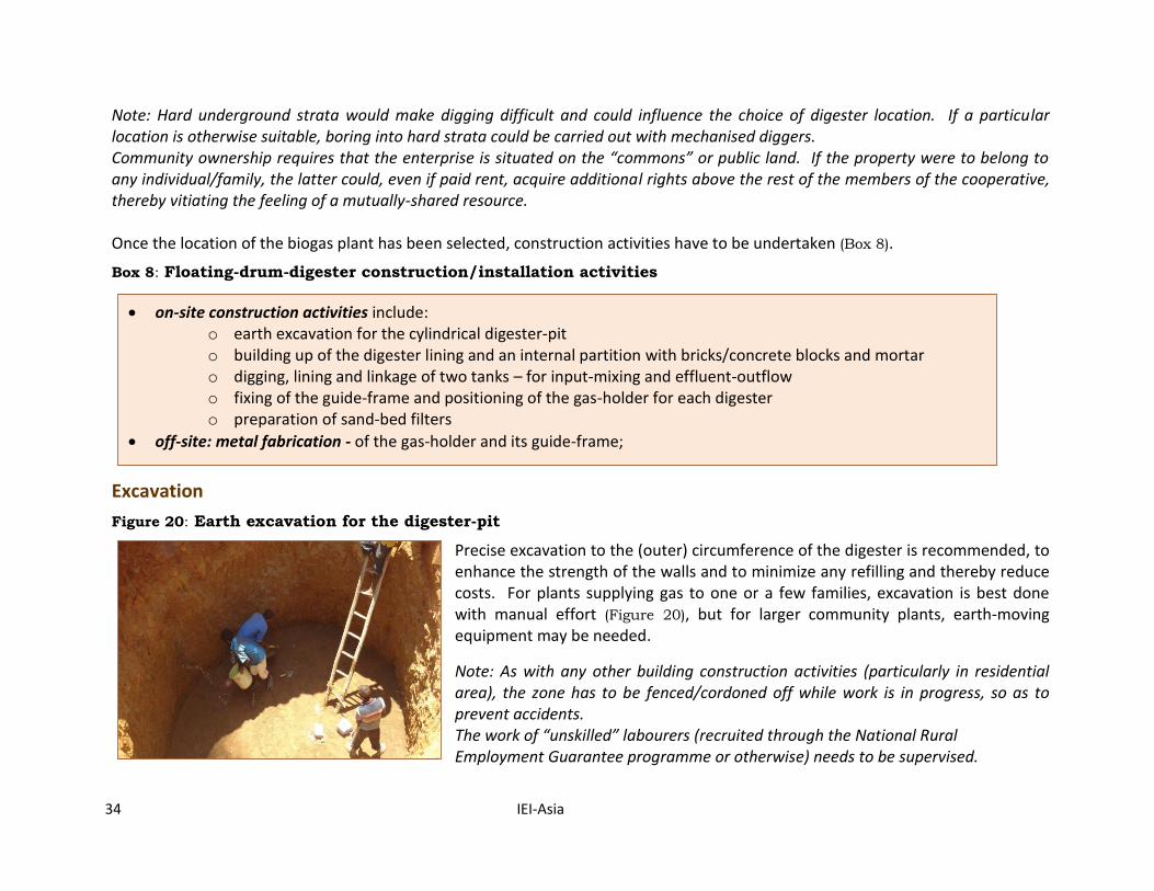
Figure 20: Earth excavation for the digester-pit
Precise excavation to the (outer) circumference of the digester is recommended, to enhance the strength of the walls and to minimize any refilling and thereby reduce costs. For plants supplying gas to one or a few families, excavation is best done with manual effort (Figure 20), but for larger community plants, earth-moving equipment may be needed.
Note: As with any other building construction activities (particularly in residential area), the zone has to be fenced/cordoned off while work is in progress, so as to prevent accidents. The work of “unskilled” labourers (recruited through the National Rural Employment Guarantee programme or otherwise) needs to be supervised.
BIOGAS GENERATION
IEI-Asia 35
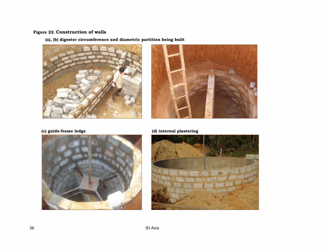
Construction of walls
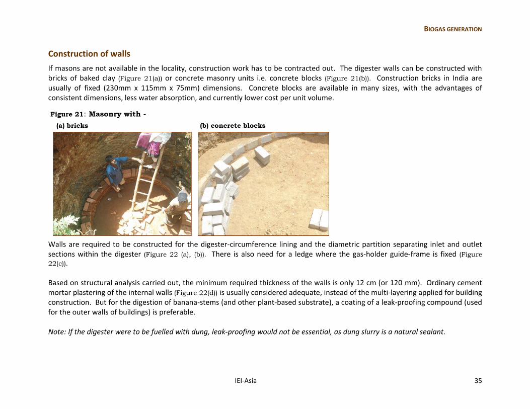
If masons are not available in the locality, construction work has to be contracted out. The digester walls can be constructed with bricks of baked clay (Figure 21(a)) or concrete masonry units i.e. concrete blocks (Figure 21(b)). Construction bricks in India are usually of fixed (230mm x 115mm x 75mm) dimensions. Concrete blocks are available in many sizes, with the advantages of consistent dimensions, less water absorption, and currently lower cost per unit volume.
Figure 21: Masonry with -
(a) bricks (b) concrete blocks
Walls are required to be constructed for the digester-circumference lining and the diametric partition separating inlet and outlet sections within the digester (Figure 22 (a), (b)). There is also need for a ledge where the gas-holder guide-frame is fixed (Figure
22(c)).
Based on structural analysis carried out, the minimum required thickness of the walls is only 12 cm (or 120 mm). Ordinary cement mortar plastering of the internal walls (Figure 22(d)) is usually considered adequate, instead of the multi-layering applied for building construction. But for the digestion of banana-stems (and other plant-based substrate), a coating of a leak-proofing compound (used for the outer walls of buildings) is preferable. Note: If the digester were to be fuelled with dung, leak-proofing would not be essential, as dung slurry is a natural sealant.
36 IEI-Asia
Figure 22: Construction of walls
(a), (b) digester circumference and diametric partition being built
(c) guide-frame ledge (d) internal plastering
BIOGAS GENERATION
IEI-Asia 37
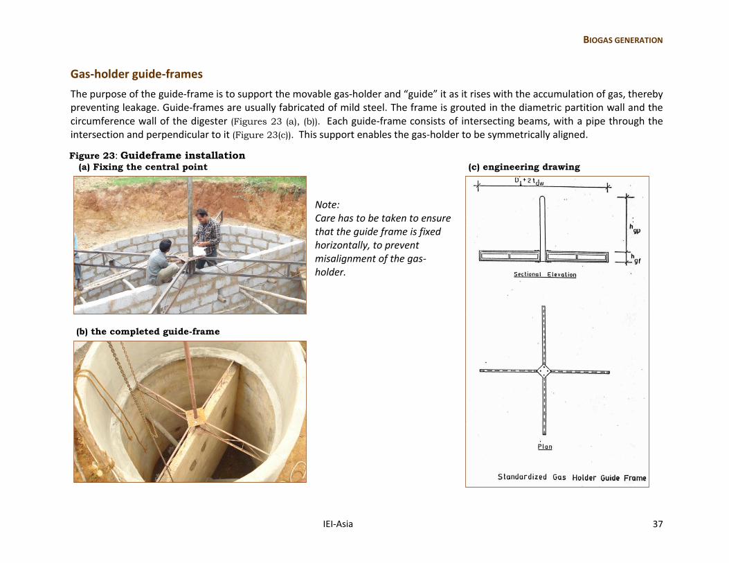
Gas-holder guide-frames
The purpose of the guide-frame is to support the movable gas-holder and “guide” it as it rises with the accumulation of gas, thereby preventing leakage. Guide-frames are usually fabricated of mild steel. The frame is grouted in the diametric partition wall and the circumference wall of the digester (Figures 23 (a), (b)). Each guide-frame consists of intersecting beams, with a pipe through the intersection and perpendicular to it (Figure 23(c)). This support enables the gas-holder to be symmetrically aligned.
Figure 23: Guideframe installation (a) Fixing the central point (c) engineering drawing
Note: Care has to be taken to ensure that the guide frame is fixed horizontally, to prevent misalignment of the gas-holder.
(b) the completed guide-frame
38 IEI-Asia
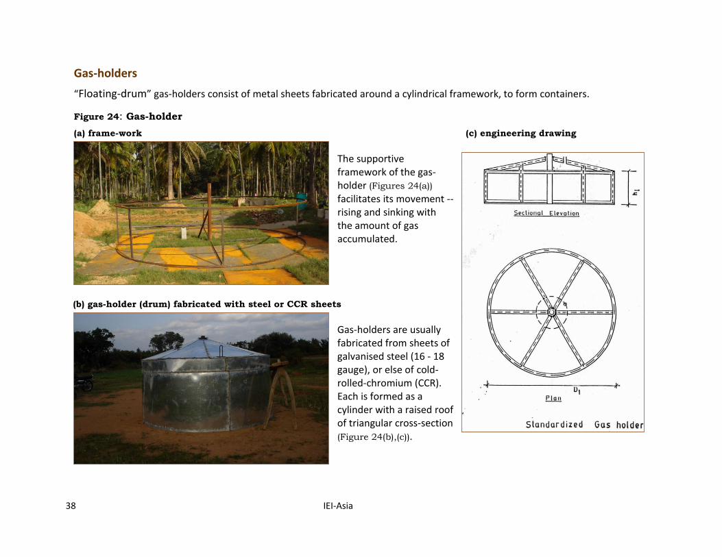
Gas-holders
“Floating-drum” gas-holders consist of metal sheets fabricated around a cylindrical framework, to form containers.
Figure 24: Gas-holder
(a) frame-work (c) engineering drawing
The supportive framework of the gas-holder (Figures 24(a)) facilitates its movement -- rising and sinking with the amount of gas accumulated.
(b) gas-holder (drum) fabricated with steel or CCR sheets
Gas-holders are usually fabricated from sheets of galvanised steel (16 - 18 gauge), or else of cold-rolled-chromium (CCR). Each is formed as a cylinder with a raised roof of triangular cross-section (Figure 24(b),(c)).
BIOGAS GENERATION
IEI-Asia 39
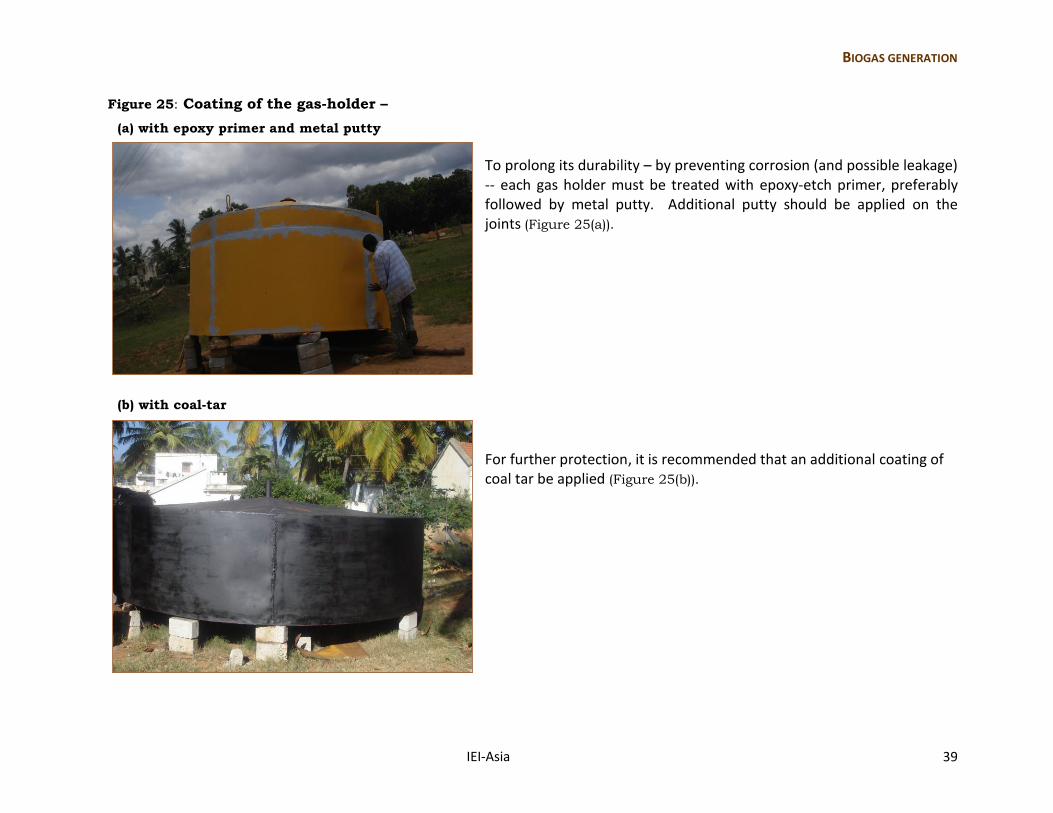
Figure 25: Coating of the gas-holder –
(a) with epoxy primer and metal putty
To prolong its durability – by preventing corrosion (and possible leakage) -- each gas holder must be treated with epoxy-etch primer, preferably followed by metal putty. Additional putty should be applied on the joints (Figure 25(a)).
(b) with coal-tar
For further protection, it is recommended that an additional coating of coal tar be applied (Figure 25(b)).
40 IEI-Asia
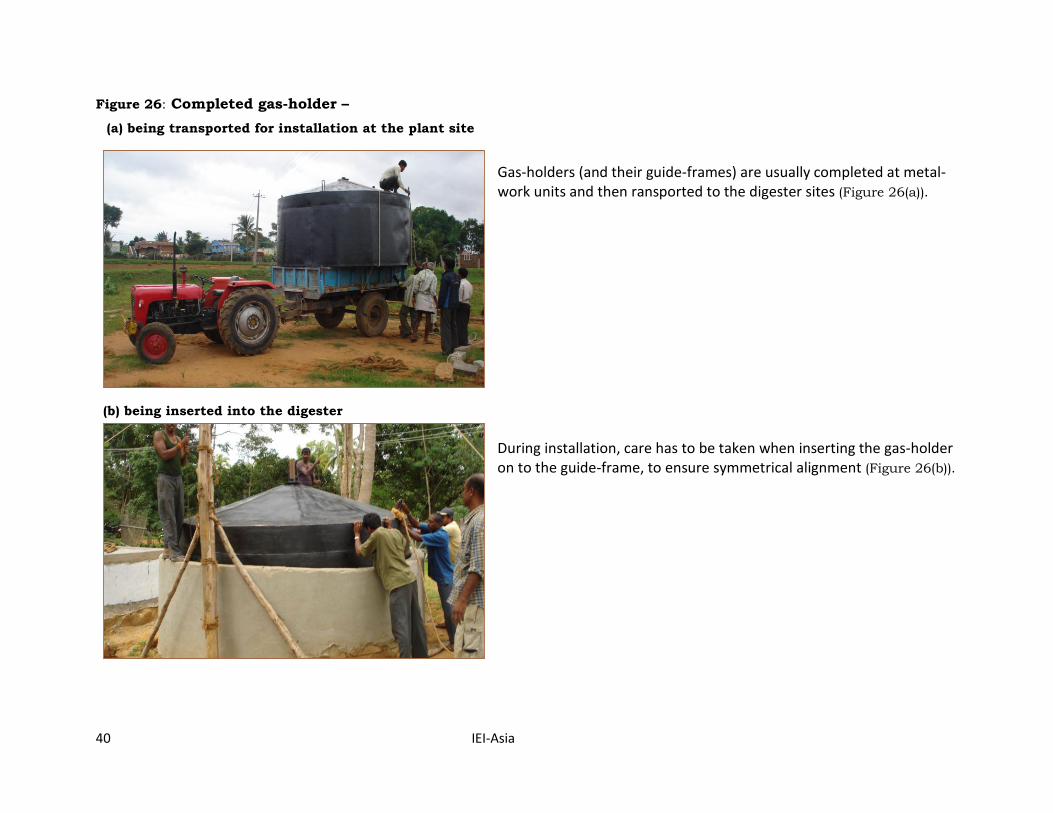
Figure 26: Completed gas-holder –
(a) being transported for installation at the plant site
Gas-holders (and their guide-frames) are usually completed at metal-work units and then ransported to the digester sites (Figure 26(a)).
(b) being inserted into the digester
During installation, care has to be taken when inserting the gas-holder on to the guide-frame, to ensure symmetrical alignment (Figure 26(b)).
BIOGAS GENERATION
IEI-Asia 41
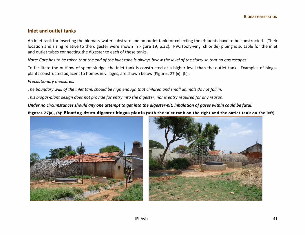
Inlet and outlet tanks
An inlet tank for inserting the biomass-water substrate and an outlet tank for collecting the effluents have to be constructed. (Their location and sizing relative to the digester were shown in Figure 19, p.32). PVC (poly-vinyl chloride) piping is suitable for the inlet and outlet tubes connecting the digester to each of these tanks.
Note: Care has to be taken that the end of the inlet tube is always below the level of the slurry so that no gas escapes.
To facilitate the outflow of spent sludge, the inlet tank is constructed at a higher level than the outlet tank. Examples of biogas plants constructed adjacent to homes in villages, are shown below (Figures 27 (a), (b)).
Precautionary measures:
The boundary wall of the inlet tank should be high enough that children and small animals do not fall in.
This biogas-plant design does not provide for entry into the digester, nor is entry required for any reason.
Under no circumstances should any one attempt to get into the digester-pit; inhalation of gases within could be fatal.
Figures 27(a), (b): Floating-drum-digester biogas plants (with the inlet tank on the right and the outlet tank on the left)
42 IEI-Asia
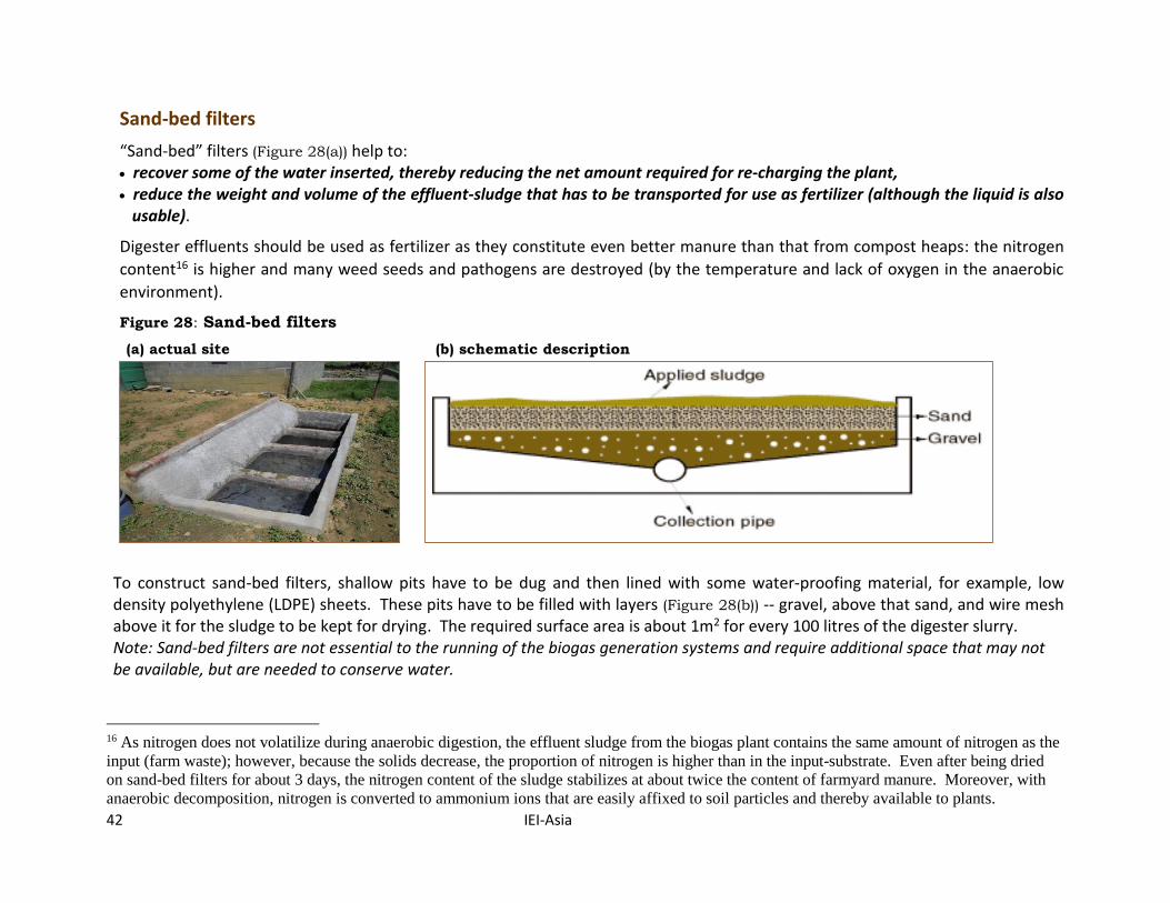
Sand-bed filters
“Sand-bed” filters (Figure 28(a)) help to: recover some of the water inserted, thereby reducing the net amount required for re-charging the plant, reduce the weight and volume of the effluent-sludge that has to be transported for use as fertilizer (although the liquid is also usable).
Digester effluents should be used as fertilizer as they constitute even better manure than that from compost heaps: the nitrogen
content16 is higher and many weed seeds and pathogens are destroyed (by the temperature and lack of oxygen in the anaerobic
environment).
Figure 28: Sand-bed filters
(a) actual site (b) schematic description
To construct sand-bed filters, shallow pits have to be dug and then lined with some water-proofing material, for example, low density polyethylene (LDPE) sheets. These pits have to be filled with layers (Figure 28(b)) -- gravel, above that sand, and wire mesh above it for the sludge to be kept for drying. The required surface area is about 1m2 for every 100 litres of the digester slurry. Note: Sand-bed filters are not essential to the running of the biogas generation systems and require additional space that may not be available, but are needed to conserve water.
16 As nitrogen does not volatilize during anaerobic digestion, the effluent sludge from the biogas plant contains the same amount of nitrogen as the
input (farm waste); however, because the solids decrease, the proportion of nitrogen is higher than in the input-substrate. Even after being dried
on sand-bed filters for about 3 days, the nitrogen content of the sludge stabilizes at about twice the content of farmyard manure. Moreover, with
anaerobic decomposition, nitrogen is converted to ammonium ions that are easily affixed to soil particles and thereby available to plants.
BIOGAS GENERATION
IEI-Asia 43
Gas delivery
Pipelines
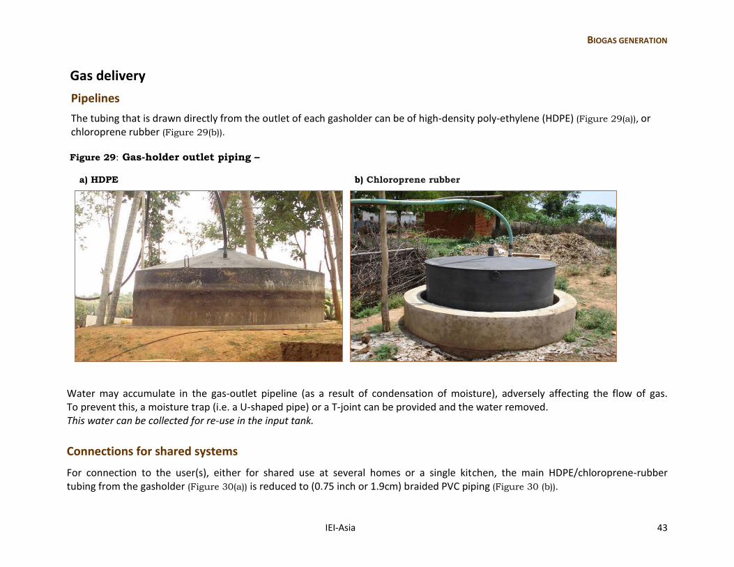
The tubing that is drawn directly from the outlet of each gasholder can be of high-density poly-ethylene (HDPE) (Figure 29(a)), or chloroprene rubber (Figure 29(b)).
Figure 29: Gas-holder outlet piping –
a) HDPE b) Chloroprene rubber
Water may accumulate in the gas-outlet pipeline (as a result of condensation of moisture), adversely affecting the flow of gas. To prevent this, a moisture trap (i.e. a U-shaped pipe) or a T-joint can be provided and the water removed. This water can be collected for re-use in the input tank.
Connections for shared systems
For connection to the user(s), either for shared use at several homes or a single kitchen, the main HDPE/chloroprene-rubber tubing from the gasholder (Figure 30(a)) is reduced to (0.75 inch or 1.9cm) braided PVC piping (Figure 30 (b)).
44 IEI-Asia
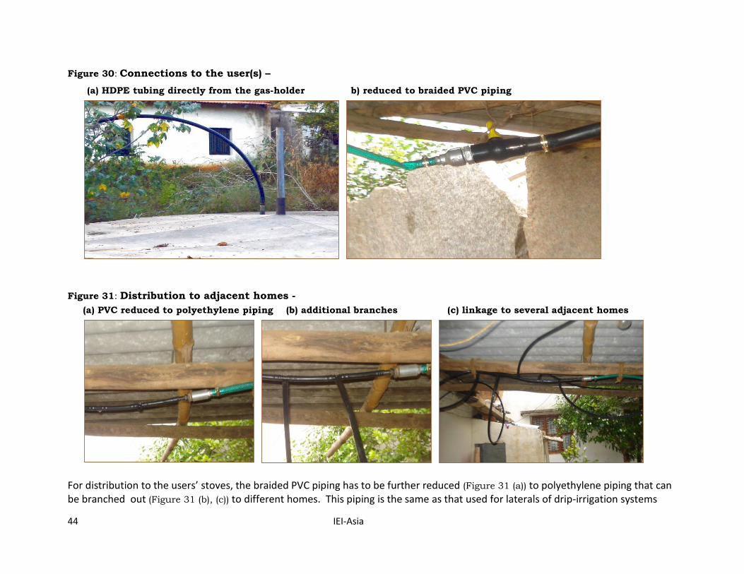
Figure 30: Connections to the user(s) –
(a) HDPE tubing directly from the gas-holder b) reduced to braided PVC piping
Figure 31: Distribution to adjacent homes -
(a) PVC reduced to polyethylene piping (b) additional branches (c) linkage to several adjacent homes
For distribution to the users’ stoves, the braided PVC piping has to be further reduced (Figure 31 (a)) to polyethylene piping that can be branched out (Figure 31 (b), (c)) to different homes. This piping is the same as that used for laterals of drip-irrigation systems
BIOGAS GENERATION
IEI-Asia 45
and therefore available with other farm supplies. As importantly, it can withstand pressure (6 kg/cm2 or 85 psi). When digesters are shared between users and gas delivery is limited to specified hours of the day, a stop-valve would also be needed to control the flow of gas.
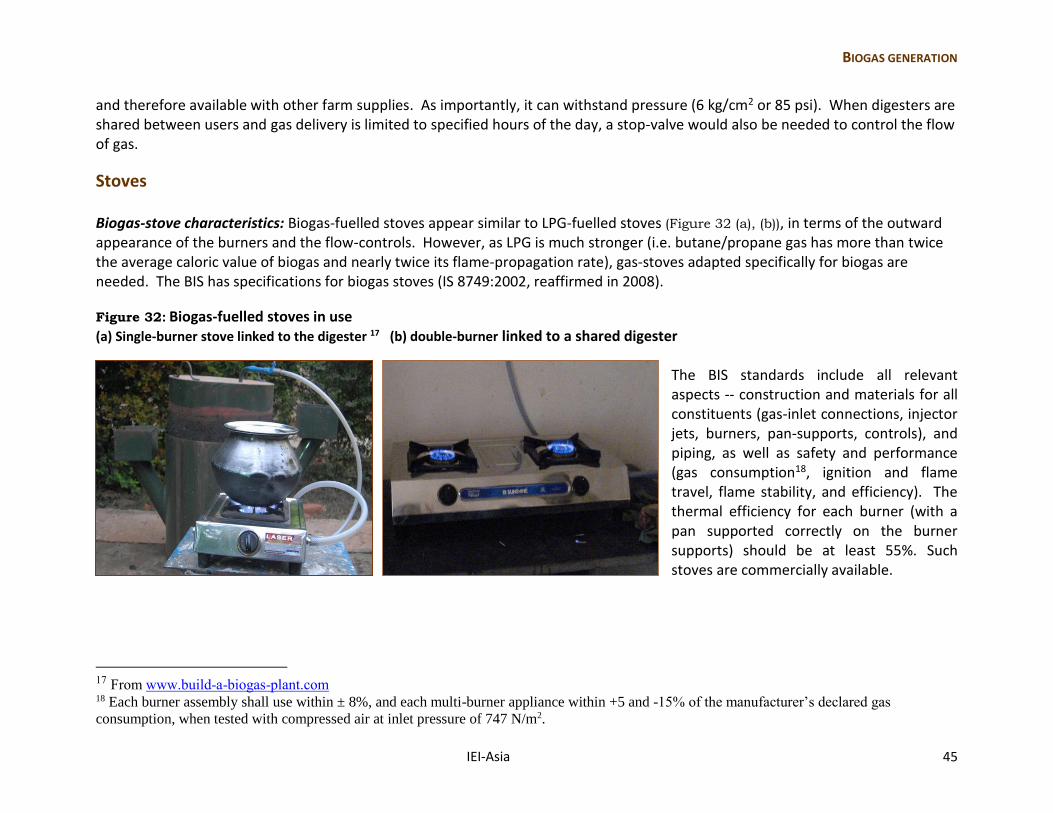
Stoves Biogas-stove characteristics: Biogas-fuelled stoves appear similar to LPG-fuelled stoves (Figure 32 (a), (b)), in terms of the outward appearance of the burners and the flow-controls. However, as LPG is much stronger (i.e. butane/propane gas has more than twice the average caloric value of biogas and nearly twice its flame-propagation rate), gas-stoves adapted specifically for biogas are needed. The BIS has specifications for biogas stoves (IS 8749:2002, reaffirmed in 2008).
Figure 32: Biogas-fuelled stoves in use
(a) Single-burner stove linked to the digester 17 (b) double-burner linked to a shared digester The BIS standards include all relevant aspects -- construction and materials for all constituents (gas-inlet connections, injector jets, burners, pan-supports, controls), and piping, as well as safety and performance (gas consumption18, ignition and flame travel, flame stability, and efficiency). The thermal efficiency for each burner (with a pan supported correctly on the burner supports) should be at least 55%. Such stoves are commercially available.
17 From www.build-a-biogas-plant.com 18 Each burner assembly shall use within ± 8%, and each multi-burner appliance within +5 and -15% of the manufacturer’s declared gas
consumption, when tested with compressed air at inlet pressure of 747 N/m2.
46 IEI-Asia
Safety While methane (CH4) is not toxic, it is flammable -- hence its use as a stove-fuel. In general, methane is very stable, but mixtures of methane and air, with the methane content between 5 and 14 percent by volume, can be explosive. In addition, as methane is naturally odourless and lighter than air, leakage may not be noticed, and escaped gas could accumulate under the roof. Therefore, the precautions taken for other gas-fuelled stoves must be taken in this case also (Box 9).
Box 9: Precautionary measures Never smoke or light a lantern near the burners.
Use stoves specifically intended for biogas-fuelling (IS 8749:2002).
Use certified hose-piping (with IS marking).
Get stoves installed by those qualified to do so. They should observe the flame at each burner. Appropriate burners have to regulate air and fuel supply, usually running slightly “lean” (i.e. with a lower fuel-to-air ratio). If the flame is too “rich” (i.e. has too much fuel), then burning is incomplete, giving carbon monoxide (which is poisonous) and carbon particles (soot).
Ensure that the piping is kept away from the burners and the matches used for lighting them, as well as hot vessels.
Regularly check that the burners are kept free from dirt that could partially block the air inlets and cause the gas/air mixture flow rate to change.
Check the piping and the point of fixture for signs of wearing down. When checking for a suspected leak, use soapy water - not a flame of any kind - to test for the presence of gas.
Periodically (about every 5 years), replace the hose-piping, even without noticeable wearing down.
BIOGAS GENERATION
IEI-Asia 47
Operation and maintenance of the biogas generation system We are providing here what has worked in the field and is of practical use on small farms, with manual preparation and without the accurate measuring devices required for laboratory precision.
Initial deposit
With inoculum: To initiate (and hasten) methanogenic bacterial action within the new substrate, it is useful to inoculate the slurry
with a small deposit or “seed” of material from another operating digester. Introducing live anaerobic bacteria expedites digestion,
and the higher the proportion of inoculum or seed material used, the quicker the process. If digestate is not available, raw cattle-
dung could be used.
Without inoculum: When no such seed material is obtained, new substrate should be added slowly (i.e. with less than the estimated
requirement during steady-state operation). During the initial period (i.e. until gas is formed), adding new material too quickly can
result in the mixture getting too acidic (pH value falling), which inhibits methane formation. A simple remedy for counteracting
acidity is adding lime/chalk.
Regular fuelling
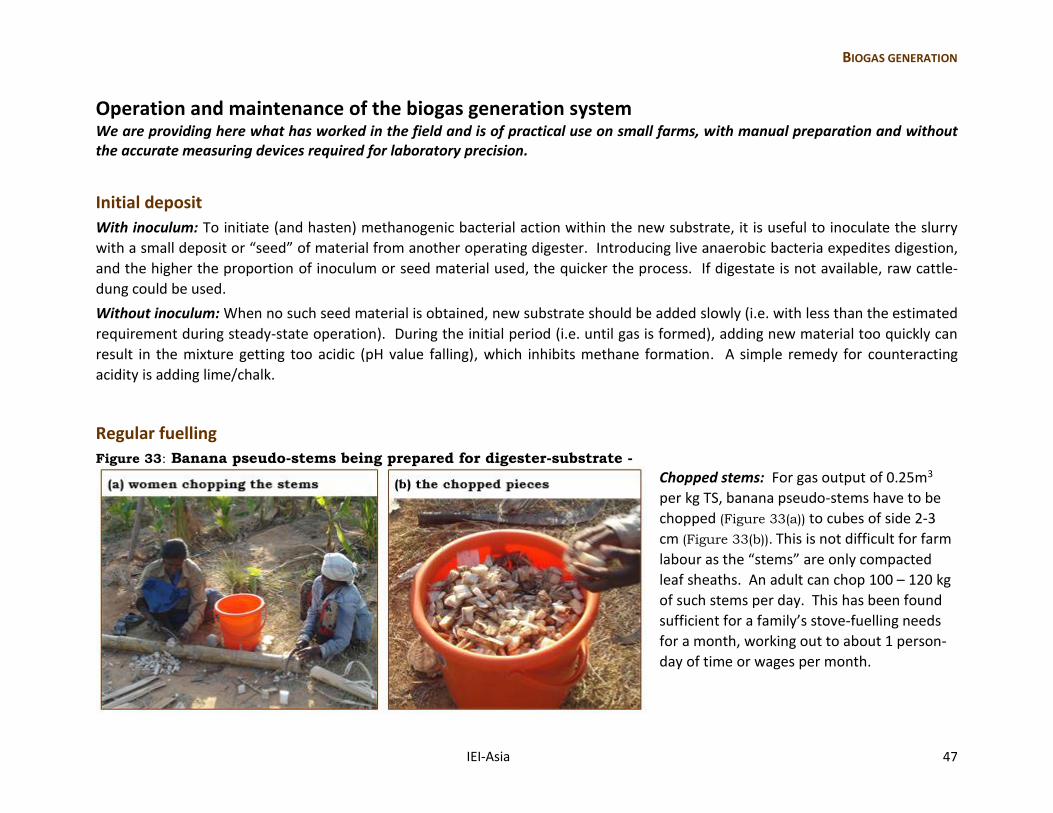
Figure 33: Banana pseudo-stems being prepared for digester-substrate -
Chopped stems: For gas output of 0.25m3
per kg TS, banana pseudo-stems have to be
chopped (Figure 33(a)) to cubes of side 2-3
cm (Figure 33(b)). This is not difficult for farm
labour as the “stems” are only compacted
leaf sheaths. An adult can chop 100 – 120 kg
of such stems per day. This has been found
sufficient for a family’s stove-fuelling needs
for a month, working out to about 1 person-
day of time or wages per month.
48 IEI-Asia
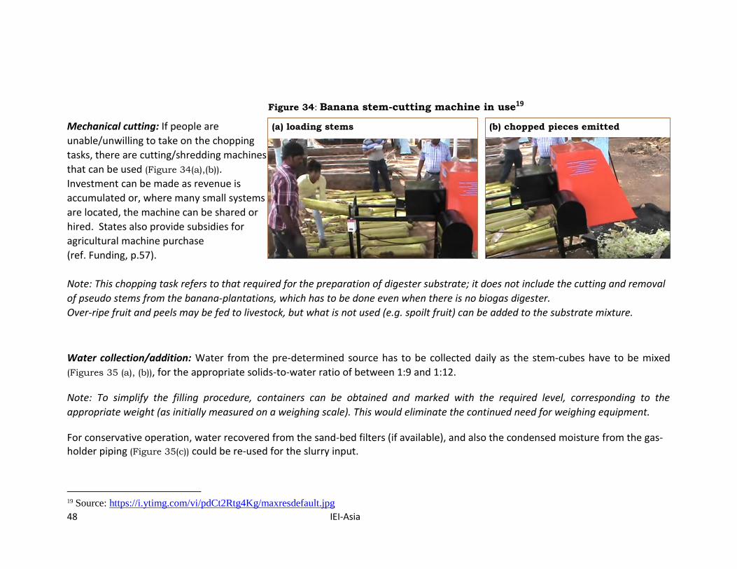
Figure 34: Banana stem-cutting machine in use19
Mechanical cutting: If people are (a) loading stems (b) chopped pieces emitted
unable/unwilling to take on the chopping
tasks, there are cutting/shredding machines
that can be used (Figure 34(a),(b)).
Investment can be made as revenue is
accumulated or, where many small systems
are located, the machine can be shared or
hired. States also provide subsidies for
agricultural machine purchase
(ref. Funding, p.57).
Note: This chopping task refers to that required for the preparation of digester substrate; it does not include the cutting and removal
of pseudo stems from the banana-plantations, which has to be done even when there is no biogas digester.
Over-ripe fruit and peels may be fed to livestock, but what is not used (e.g. spoilt fruit) can be added to the substrate mixture.
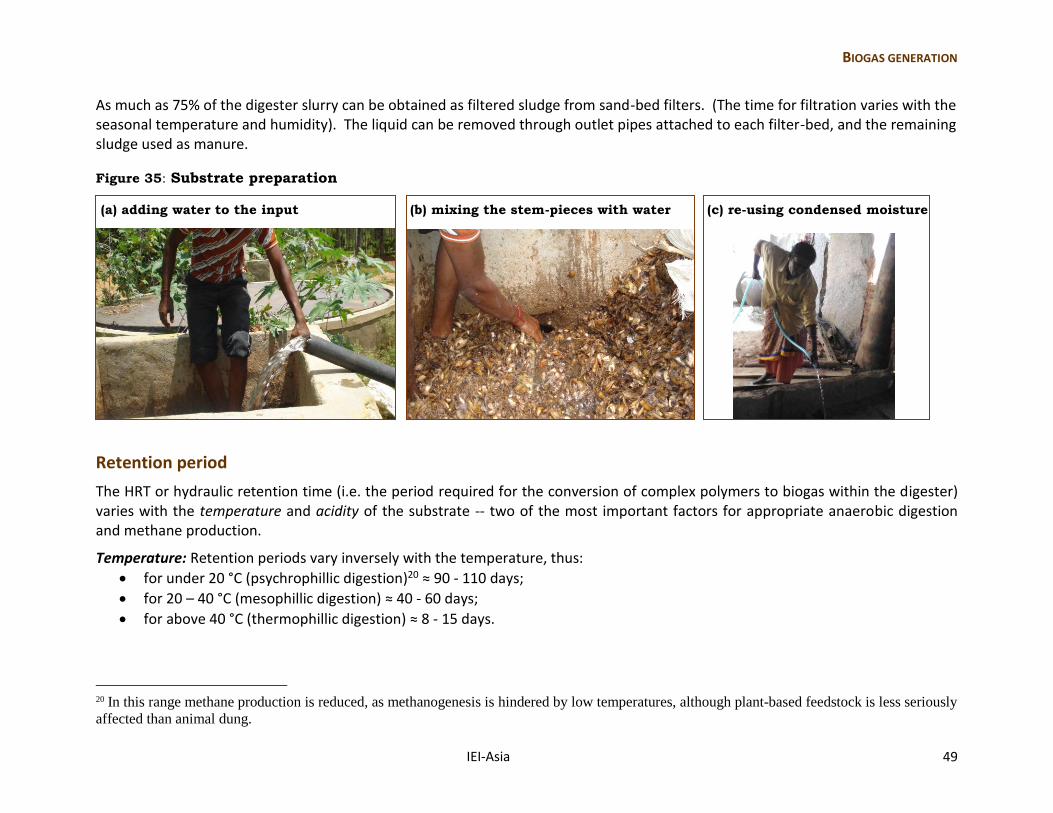
Water collection/addition: Water from the pre-determined source has to be collected daily as the stem-cubes have to be mixed
(Figures 35 (a), (b)), for the appropriate solids-to-water ratio of between 1:9 and 1:12.
Note: To simplify the filling procedure, containers can be obtained and marked with the required level, corresponding to the
appropriate weight (as initially measured on a weighing scale). This would eliminate the continued need for weighing equipment.
For conservative operation, water recovered from the sand-bed filters (if available), and also the condensed moisture from the gas-holder piping (Figure 35(c)) could be re-used for the slurry input.
19 Source: https://i.ytimg.com/vi/pdCt2Rtg4Kg/maxresdefault.jpg
BIOGAS GENERATION
IEI-Asia 49
As much as 75% of the digester slurry can be obtained as filtered sludge from sand-bed filters. (The time for filtration varies with the seasonal temperature and humidity). The liquid can be removed through outlet pipes attached to each filter-bed, and the remaining sludge used as manure.
Figure 35: Substrate preparation
(a) adding water to the input (b) mixing the stem-pieces with water (c) re-using condensed moisture
Retention period
The HRT or hydraulic retention time (i.e. the period required for the conversion of complex polymers to biogas within the digester) varies with the temperature and acidity of the substrate -- two of the most important factors for appropriate anaerobic digestion and methane production.
Temperature: Retention periods vary inversely with the temperature, thus:
for under 20 °C (psychrophillic digestion)20 ≈ 90 - 110 days;
for 20 – 40 °C (mesophillic digestion) ≈ 40 - 60 days;
for above 40 °C (thermophillic digestion) ≈ 8 - 15 days.
20 In this range methane production is reduced, as methanogenesis is hindered by low temperatures, although plant-based feedstock is less seriously
affected than animal dung.
50 IEI-Asia
Without applying additional heat, mesophillic conditions would be experienced within digesters in most parts of India (except in winter, when the retention period would have to be longer). Note: While mesophillic temperatures in tropical regions enable initial gas formation in about 40 days, to ensure daily gas availability, it is preferable to commence gas withdrawal after accumulation of the full capacity of the gas-holder drum. Thereafter, with daily substrate loading, continuous gas supply can be expected. Acidity: The pH factor (i.e. the level of acidity or alkalinity) is important because methanogenic bacteria are sensitive to acidic environments, so much so that fermentation can stop if the acidity increase early during digestion21 resulted in pH values of 6 or below. (Digestion is most effective at the neutral point where pH = 7). Note: If gas does not start accumulating (and there is no other problem such as leakage), it is likely to be due to acidity. This can be treated by adding small amounts of lime, ammonia, or baking soda. Alternatively, periodic gaps (of one/two days, about two weeks apart) in the insertion of digestate could help to avoid excess acidification.
Gas-holder maintenance If the initial preparation of the gas-holder has been adequate – with epoxy, metal putty, and coal-tar coatings – further maintenance against corrosion is not required for several years. Otherwise, “re-painting” of the gas-holder (with coal-tar) may be needed. Mild shaking or partial rotation of the gas-holder is desirable to prevent a layer of scum forming on the surface of the substrate (that could hinder gas production and withdrawal). Also, keeping substrate materials in suspension assists in the uniform breakdown of the material and promotes complete digestion.
21 In the early stages of the anaerobic process (i.e. when acidogenic bacteria are at work) the pH can drop to 6 or below. When the process reaches
methanogenesis, pH will be in the 7.5 to 8.5 range (i.e. slightly alkaline). It had been observed (Nirmala et al., 1996, Velmurugan and
Ramanujam, 2001, Clarke et al., 2005), that the accumulation of volatile fatty acids during anaerobic digestion reduces methanogenic activity
(with conversion of acetates to methane being the rate-limiting factor), and this slows down the production of gas.
BIOGAS GENERATION
IEI-Asia 51
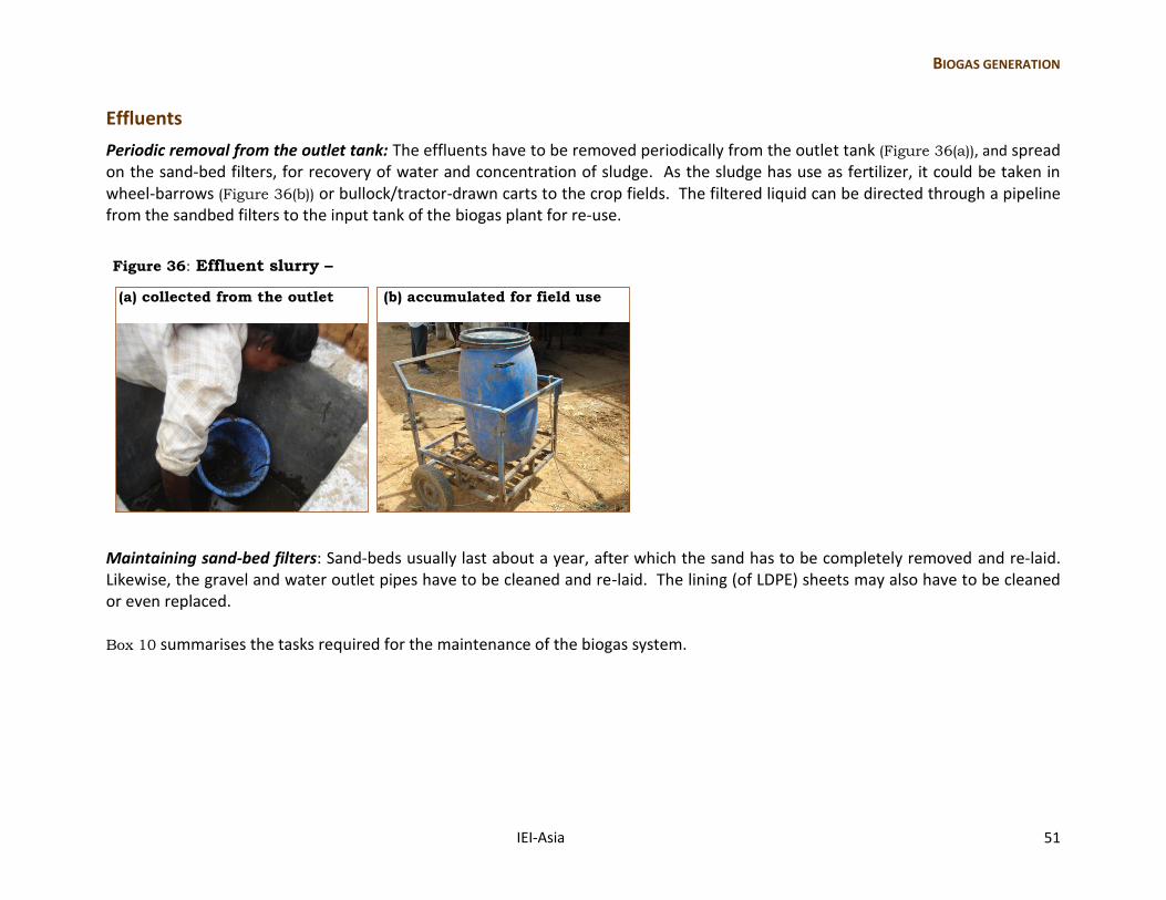
Effluents
Periodic removal from the outlet tank: The effluents have to be removed periodically from the outlet tank (Figure 36(a)), and spread on the sand-bed filters, for recovery of water and concentration of sludge. As the sludge has use as fertilizer, it could be taken in wheel-barrows (Figure 36(b)) or bullock/tractor-drawn carts to the crop fields. The filtered liquid can be directed through a pipeline from the sandbed filters to the input tank of the biogas plant for re-use.
Figure 36: Effluent slurry –
(a) collected from the outlet (b) accumulated for field use
Maintaining sand-bed filters: Sand-beds usually last about a year, after which the sand has to be completely removed and re-laid. Likewise, the gravel and water outlet pipes have to be cleaned and re-laid. The lining (of LDPE) sheets may also have to be cleaned or even replaced. Box 10 summarises the tasks required for the maintenance of the biogas system.
52 IEI-Asia
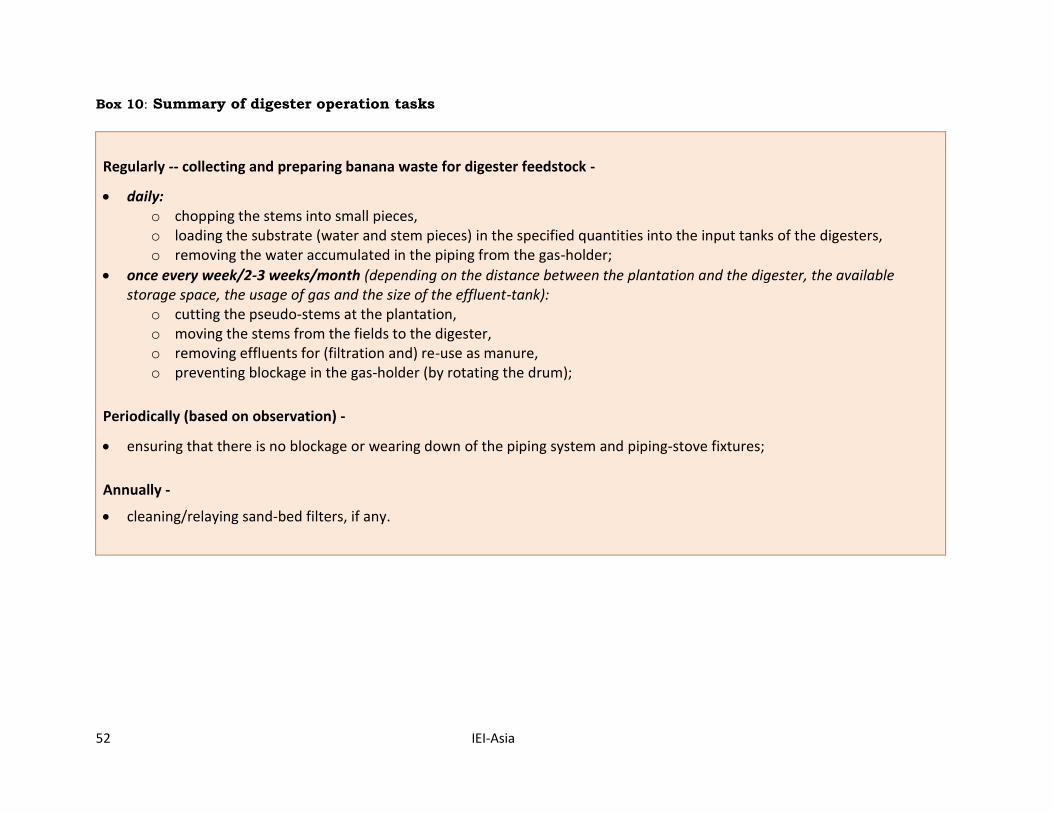
Box 10: Summary of digester operation tasks
Regularly -- collecting and preparing banana waste for digester feedstock -
daily: o chopping the stems into small pieces, o loading the substrate (water and stem pieces) in the specified quantities into the input tanks of the digesters, o removing the water accumulated in the piping from the gas-holder;
once every week/2-3 weeks/month (depending on the distance between the plantation and the digester, the available storage space, the usage of gas and the size of the effluent-tank):
o cutting the pseudo-stems at the plantation, o moving the stems from the fields to the digester, o removing effluents for (filtration and) re-use as manure, o preventing blockage in the gas-holder (by rotating the drum);
Periodically (based on observation) -
ensuring that there is no blockage or wearing down of the piping system and piping-stove fixtures;
Annually -
cleaning/relaying sand-bed filters, if any.
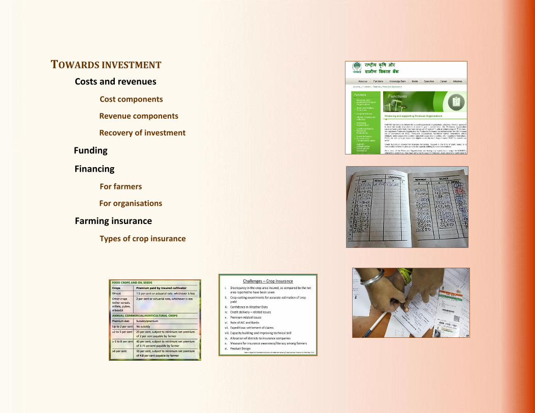
TOWARDS INVESTMENT
IEI-Asia 53
TOWARDS INVESTMENT
Costs and revenues
Cost components
Revenue components
Recovery of investment
Funding
Financing
For farmers
For organisations
Farming insurance
Types of crop insurance
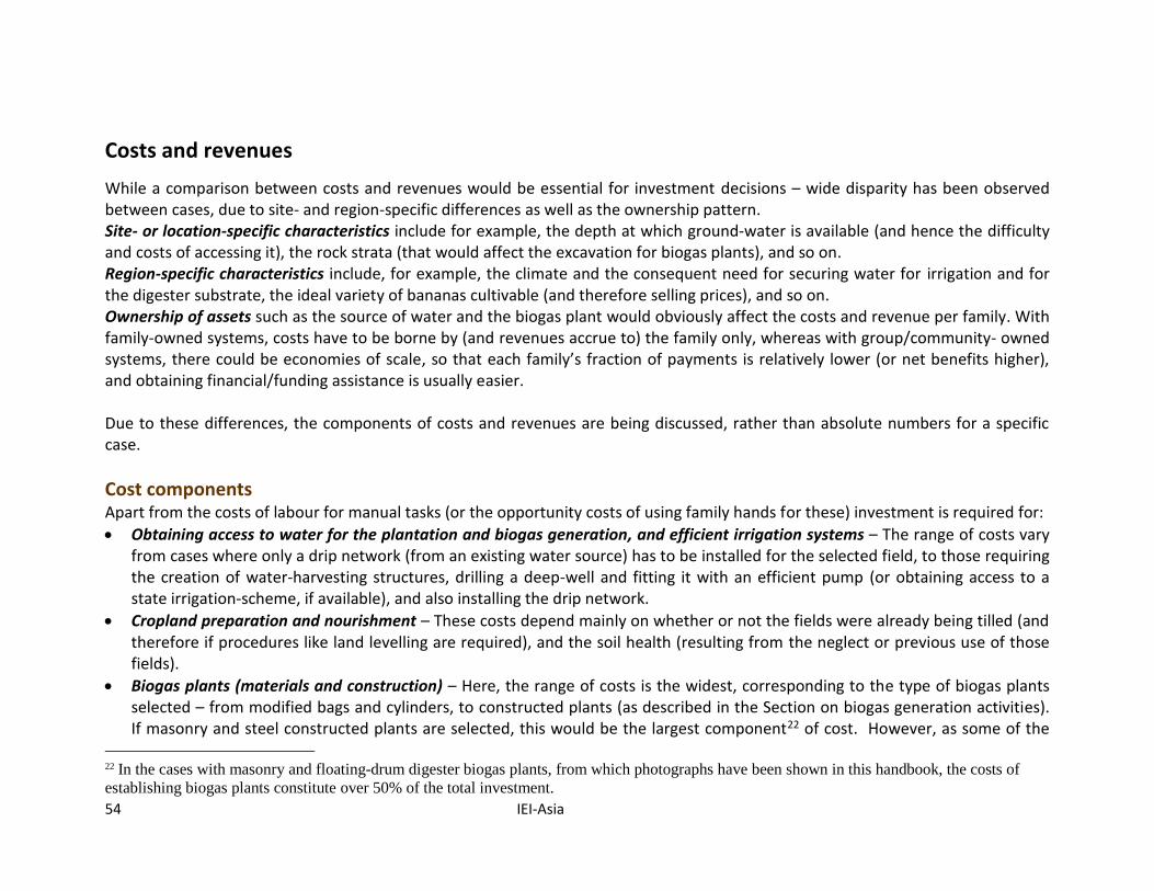
54 IEI-Asia
Costs and revenues
While a comparison between costs and revenues would be essential for investment decisions – wide disparity has been observed between cases, due to site- and region-specific differences as well as the ownership pattern. Site- or location-specific characteristics include for example, the depth at which ground-water is available (and hence the difficulty and costs of accessing it), the rock strata (that would affect the excavation for biogas plants), and so on. Region-specific characteristics include, for example, the climate and the consequent need for securing water for irrigation and for the digester substrate, the ideal variety of bananas cultivable (and therefore selling prices), and so on. Ownership of assets such as the source of water and the biogas plant would obviously affect the costs and revenue per family. With family-owned systems, costs have to be borne by (and revenues accrue to) the family only, whereas with group/community- owned systems, there could be economies of scale, so that each family’s fraction of payments is relatively lower (or net benefits higher), and obtaining financial/funding assistance is usually easier. Due to these differences, the components of costs and revenues are being discussed, rather than absolute numbers for a specific case.
Cost components
Apart from the costs of labour for manual tasks (or the opportunity costs of using family hands for these) investment is required for:
Obtaining access to water for the plantation and biogas generation, and efficient irrigation systems – The range of costs vary from cases where only a drip network (from an existing water source) has to be installed for the selected field, to those requiring the creation of water-harvesting structures, drilling a deep-well and fitting it with an efficient pump (or obtaining access to a state irrigation-scheme, if available), and also installing the drip network.
Cropland preparation and nourishment – These costs depend mainly on whether or not the fields were already being tilled (and therefore if procedures like land levelling are required), and the soil health (resulting from the neglect or previous use of those fields).
Biogas plants (materials and construction) – Here, the range of costs is the widest, corresponding to the type of biogas plants selected – from modified bags and cylinders, to constructed plants (as described in the Section on biogas generation activities). If masonry and steel constructed plants are selected, this would be the largest component22 of cost. However, as some of the
22 In the cases with masonry and floating-drum digester biogas plants, from which photographs have been shown in this handbook, the costs of
establishing biogas plants constitute over 50% of the total investment.
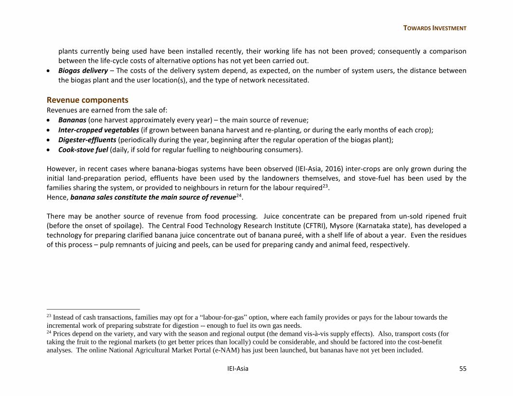
TOWARDS INVESTMENT
IEI-Asia 55
plants currently being used have been installed recently, their working life has not been proved; consequently a comparison between the life-cycle costs of alternative options has not yet been carried out.
Biogas delivery – The costs of the delivery system depend, as expected, on the number of system users, the distance between the biogas plant and the user location(s), and the type of network necessitated.
Revenue components
Revenues are earned from the sale of:
Bananas (one harvest approximately every year) – the main source of revenue;
Inter-cropped vegetables (if grown between banana harvest and re-planting, or during the early months of each crop);
Digester-effluents (periodically during the year, beginning after the regular operation of the biogas plant);
Cook-stove fuel (daily, if sold for regular fuelling to neighbouring consumers). However, in recent cases where banana-biogas systems have been observed (IEI-Asia, 2016) inter-crops are only grown during the initial land-preparation period, effluents have been used by the landowners themselves, and stove-fuel has been used by the families sharing the system, or provided to neighbours in return for the labour required23. Hence, banana sales constitute the main source of revenue24. There may be another source of revenue from food processing. Juice concentrate can be prepared from un-sold ripened fruit (before the onset of spoilage). The Central Food Technology Research Institute (CFTRI), Mysore (Karnataka state), has developed a technology for preparing clarified banana juice concentrate out of banana pureé, with a shelf life of about a year. Even the residues of this process – pulp remnants of juicing and peels, can be used for preparing candy and animal feed, respectively.
23 Instead of cash transactions, families may opt for a “labour-for-gas” option, where each family provides or pays for the labour towards the
incremental work of preparing substrate for digestion -- enough to fuel its own gas needs. 24 Prices depend on the variety, and vary with the season and regional output (the demand vis-à-vis supply effects). Also, transport costs (for
taking the fruit to the regional markets (to get better prices than locally) could be considerable, and should be factored into the cost-benefit
analyses. The online National Agricultural Market Portal (e-NAM) has just been launched, but bananas have not yet been included.
56 IEI-Asia
Recovery of investment
The revenue from the sale of bananas has been found adequate25 to recover the initial investment and the operational costs of banana cultivation – chiefly the additional fertilizers that have to be purchased and the costs of hired labour (or the opportunity costs of self-employment), as electricity for irrigation is practically free in most states. However, the additional investment for biogas generation is recoverable only through the avoided costs of equivalent amounts of LPG (that are subsidised by the government, but may involve some unofficial premium for regular rural supply), and the fertilizer value of the effluents. Additional generation of gas for sale necessitates labour costs that reduce the net earning. Hence, some support is needed to recover the investment made for constructed biogas plants. This is justifiable in view of the environmental and health benefits of reduced emissions from burning solid biomass and the reduced state burden of subsidies for LPG production and distribution. It is therefore useful to consider the available options for state funding (non-repayable grants) and financing (amounts repayable with interest), and also the insurance protection that could be availed of.
Funding Figure 37: A new account There are funds disbursed by the government, through its development agencies, towards defraying the costs of some components of banana-biogas systems. The government has been focusing on the provision of identity cards to all individuals, and based on these, the extension of bank accounts to all adults (even the illiterate, Figure 37). These are expected to facilitate credit access.
For drip-irrigation systems (for banana cultivation): Since the National Mission on Micro-irrigation (2010), at least 50% subsidy is available for drip systems, i.e. 40% from the central government’s budget and 10% (or more) from the state government. In the case of special categories (Scheduled Castes and Tribes) or focused districts, the subsidy is higher.
25 Exceptions include the occasions when crops fail due to natural calamities, but some insurance coverage is possible (ref. Farming insurance).
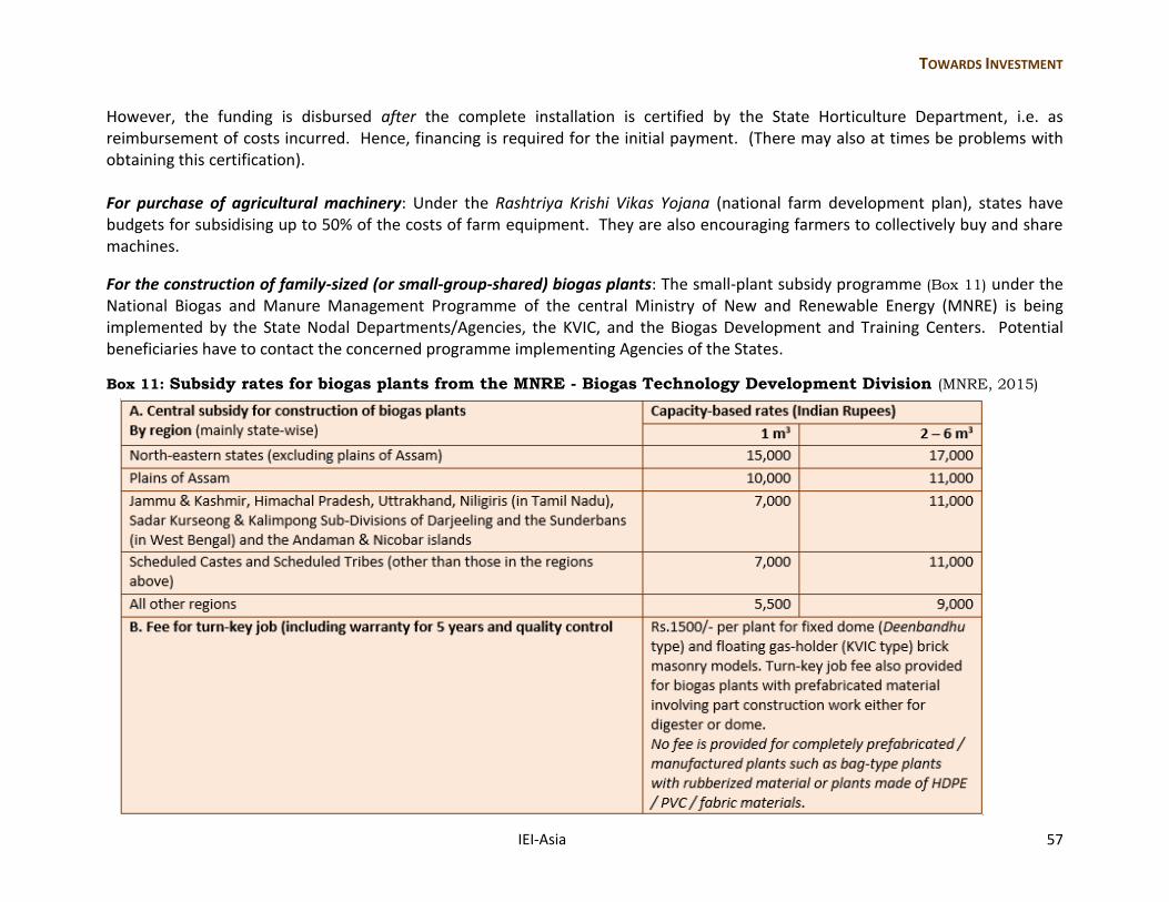
TOWARDS INVESTMENT
IEI-Asia 57
However, the funding is disbursed after the complete installation is certified by the State Horticulture Department, i.e. as reimbursement of costs incurred. Hence, financing is required for the initial payment. (There may also at times be problems with obtaining this certification). For purchase of agricultural machinery: Under the Rashtriya Krishi Vikas Yojana (national farm development plan), states have budgets for subsidising up to 50% of the costs of farm equipment. They are also encouraging farmers to collectively buy and share machines.
For the construction of family-sized (or small-group-shared) biogas plants: The small-plant subsidy programme (Box 11) under the National Biogas and Manure Management Programme of the central Ministry of New and Renewable Energy (MNRE) is being implemented by the State Nodal Departments/Agencies, the KVIC, and the Biogas Development and Training Centers. Potential beneficiaries have to contact the concerned programme implementing Agencies of the States.
Box 11: Subsidy rates for biogas plants from the MNRE - Biogas Technology Development Division (MNRE, 2015)
58 IEI-Asia
Financing While partial reimbursement of the expenses already incurred is possible, financing would be required for those who cannot incur the initial costs – the parts that may be reimbursed and the non-refundable components. Institutional sources are listed here.
For farmers (or groups of farmers) Nationalised Banks (and also some private banks): As Banks have to lend against collateral, the poor are usually eliminated. Where collateral can be provided (e.g. land ownership documents in the name of the person taking the loan), concessionary financing can be obtained from many banks (e.g. repayment over 10 - 15 years, after a grace period of 11 months for existing crop-lands, and until the first yield for newly cultivated fields). Even without individual collateral, informal associations of people such as SHGs (self-help-groups of around 20 people who pool their small savings towards a common fund) could get bank loans at concessionary rates. Thus far, banks have been lending to SHGs engaged in economic activities such as preparation of food-based products, sewing, weaving, and other such activities. The SHG procures finance from the Bank and in turn gives loans to its members at a slightly higher rate. For water-recharge systems: The central-government-run Krishi Pragati Grameen Bank (farm progress rural bank) offers loans of up to Rs 20,000 to farmers, depending on the size of the farms, for the purpose of constructing re-charge bore-wells and other structures. Figure 38: NABARD web site
For organisations NABARD: The National Bank for Agriculture and Rural Development (ref. www.nabard.org, Figure 38) was established by the Government of India for the promotion of agriculture, small-scale and cottage industries in rural regions, and handicrafts and other crafts of rural-based people. Funding options that could be relevant to the development of banana plantations and biogas generation are being listed.
TOWARDS INVESTMENT
IEI-Asia 59
Rural Infrastructure Development Fund (RIDF) has been created by the central government from money that banks forfeit in each financial year when they do not meet their priority sector targets26. It is administered by NABARD for several uses. Area-based schemes: NABARD has been identifying area-based schemes (ABS) in each state, in the sectors of dairy, agro-processing, storage, plantations, horticulture, and sericulture. The adoption of ABS is expected to have forward and backward linkages that would result in increased credit for the adoption of better technology and practices. Village-based micro-infrastructure: NABARD is also interested in funding micro-infrastructure projects carried out by the gram panchayat from the RIDF. The projects include “micro-infrastructure” -- deep wells, sanitary facilities, warehouses to store farm produce, farm equipment (for joint-ownership), and small electrification (solar/biogas/wind) projects. Non-banking finance for farmers’ producer-organisations: NABARD had set up a Producers Organisation Development Fund (PODF) in the year 2011. Now, to support farmers organising themselves in producers’ associations, NABARD intends setting up a wholly-owned non-banking finance company under the aegis of the PODF. It is believed that farm-producers’ organisations could counter the inability of individual small farms to access credit for using better technology and other improvements. “Mudra”: The Micro-Unit Development and Refinance Agency (MUDRA) Bank, an institution established in 2015, works in association with banks and micro-finance institutions to help small businesses secure funds for asset-purchase. Thus far, manufacturing and trade have been mentioned, but perhaps generation of energy could also be considered. There are three options depending on the amounts funded – till Rs 50,000 (Shishu), Rs 50,000 – 5 lakhs (Kishore), and Rs 5 – 10 lakhs (Tarun).
Farming Insurance Farming-insurance can be considered a component of agricultural financing because (when operating efficiently) it provides much-needed financial support to farmers experiencing crop losses. At times of natural disasters, the central/state governments offer some compensation, but this is usually very low compared to the value of the crop lost; hence, prior insurance should be considered essential. Unfortunately, only about 25% of Indian farmers have some crop insurance (NSSO, 2014), mainly in cases where the insurance premium is directly deducted from institutional agricultural loans (being an essential pre-requisite for obtaining them).
26 Nationalised banks have to set aside 40% of their total loan portfolio for priority sectors such as micro and small enterprises, education and
affordable housing.
60 IEI-Asia
Types of crop insurance Two types of crop-insurance have been in use in India for several years -- one meant to protect against lower-than-expected yield and the other meant to protect against unexpected weather effects, as explained below. The new Pradhan Mantri Fasal Bima Yojana (PMFBY), launched in 2015-16, is supposed to be an improved combination of these. The Modified National Agriculture Insurance Scheme (MNAIS): This crop-yield-based scheme had been implemented chiefly by the central-government owned Agricultural Insurance Company of India Limited. Compensation was on the basis of comparison between the actual yield and the calculated average yield for the reference unit area (usually a village) over the previous (usually 7) years. Computation of losses included pre- and post-harvest losses for about 65 different crops. Weather Based Crop Insurance Scheme: The weather-based insurance provided compensation per unit area, for sub-normal rainfall, with the amount linked to the growing phases -- sowing, flowering and harvesting seasons, for each of the specified crops. It also included compensation for pest infestation and floods. The averages were computed on the basis of the previous 25 years’ data. While there has not been enough time to assess its implementation, the proposed benefits of the new PMFBY include:
There is intended to be no cap (upper limit) on the premium acceptable for a particular insured amount. (Earlier, because of the limit on the premium chargeable, insurers lowered the insurance amount correspondingly; however, there continue to be limits imposed in order to reduce the insured sums payable).
The adverse weather coverage has been widened, e.g., losses due to cyclones can be claimed around the country, instead of only in coastal regions, and losses for both prevention of sowing and post-harvest spoilage are now available.
However, the increases in benefits are based on an increased subsidy component from the state governments. It is still unclear whether or not this subsidy component will be realizable as it constitutes a very high component of the states’ agricultural budgets and some states are currently implementing the scheme in only a few districts, on a pilot basis.
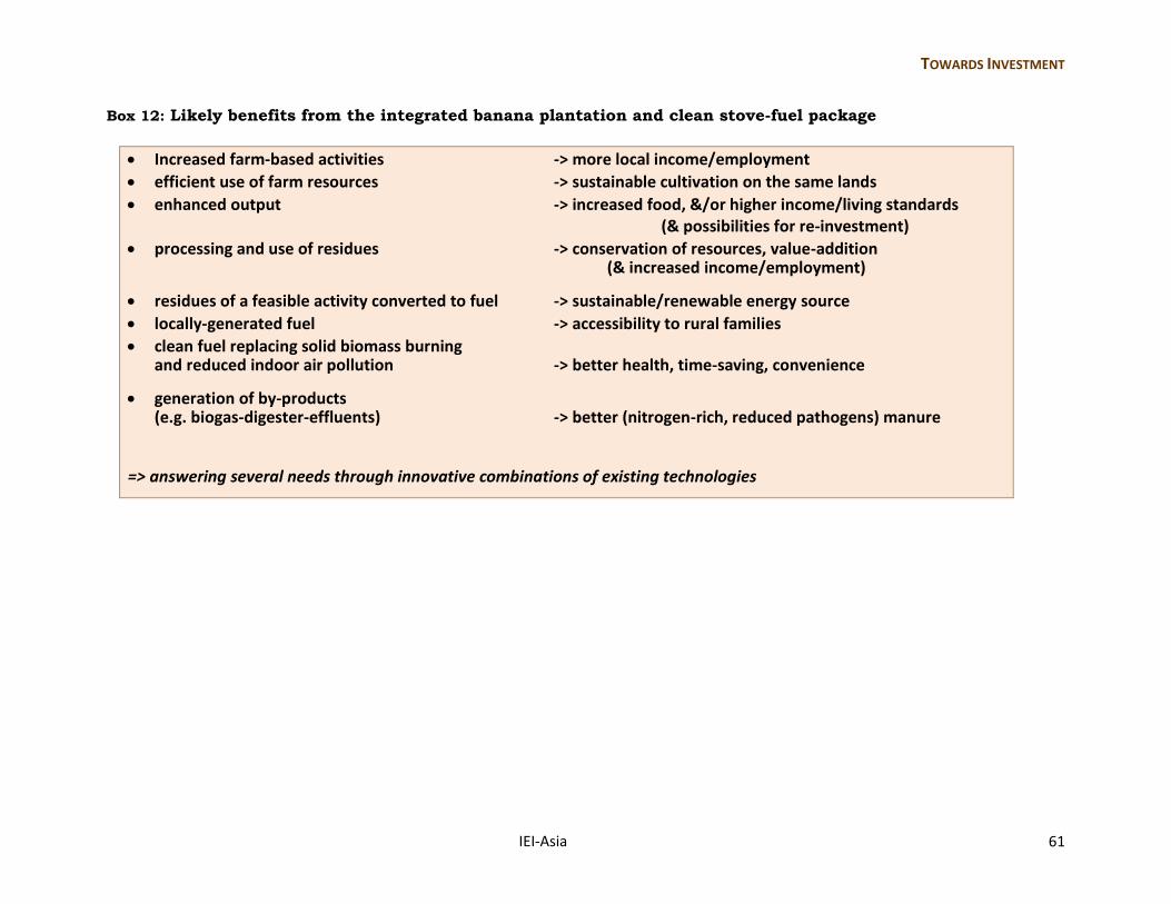
TOWARDS INVESTMENT
IEI-Asia 61
Box 12: Likely benefits from the integrated banana plantation and clean stove-fuel package
Increased farm-based activities -> more local income/employment
efficient use of farm resources -> sustainable cultivation on the same lands
enhanced output -> increased food, &/or higher income/living standards (& possibilities for re-investment)
processing and use of residues -> conservation of resources, value-addition (& increased income/employment)
residues of a feasible activity converted to fuel -> sustainable/renewable energy source
locally-generated fuel -> accessibility to rural families
clean fuel replacing solid biomass burning and reduced indoor air pollution -> better health, time-saving, convenience
generation of by-products (e.g. biogas-digester-effluents) -> better (nitrogen-rich, reduced pathogens) manure
=> answering several needs through innovative combinations of existing technologies
62 IEI-Asia
Further reading
Appropriate Rural Technology Institute (ARTI) web site, Technologies and Products Sections, viewed in 2016 at
http://www.arti-india.org
Argyropoulos, D., Khan, M.T., Maurer, C., Brule, M., and Mueller, J., (University of Hohenheim, Department of Agricultural
Engineering, Tropics and Subtropics Group), 2009. “Anaerobic Digestion of Banana Waste, a Potential Source of Energy in Uganda”,
Biophysical and Socio-economic Frame Conditions for the Sustainable Management of Natural Resources, 6-8 October, Hamburg.
ASTRA (Centre for the Application of Science and Technology to Rural Areas), 1990. Biogas-diesel engines for lighting and pumping
drinking water in villages: Pura community biogas plant system experience, Proceedings of the third international conference on small
engines and their fuels for use in rural area: development, operation and maintenance, University of Reading, United Kingdom.
Bahadur, S. and Agarwal, S.C., 1980. Community Biogas Plant at Fateh Singh ka Purwa – An Evaluation, Planning Research and Action
Division, State Planning Institute, Lucknow (Uttar Pradesh, India).
CGWB-MoWR (GoI), 2006. Dynamic Ground Water Resources of India (March 2004), Central Ground Water Board, Ministry of Water
Resources, Government of India, Faridabad, 2006, accessed in November 2009 from
http://cgwb.gov.in/GroundWater/GW_assessment.htm
Clarke W., Radnigge, P., Lai, E., Jensen, P., and Hardin, M., 2005. Digestion of waste bananas to generate energy in Australia,
Proceedings Sardinia 2005, Tenth International Waste Management and Landfill Symposium, Italia, 3-7 October.
D’Sa, Antonette and Narasimha Murthy, K. V., 2004. “LPG as a cooking fuel option for India”, Energy for Sustainable Development, Vol.
VIII, No.3, September, pp.91-106.
D’Sa, Antonette, 2010. “Efficient groundwater-based irrigation in India - Experiences with implementing irrigation efficiency”,
International Energy Initiative - Asian Regional Initiative, August, (currently available at http://iei-asia.org/IEI-Bangalore-
EfficientGWIrrigation-Compilation-Report.pdf)
DST (Department of Science and Technology), 1979. All-India Co-ordinated Project on Biogas Technology and Utilisation – Progress
Report, Department of Science and Technology, Government of India.
DtE (Down to Earth), 2016. DROUGHT:In-depth Coverage – “A few villages from the drought-ravaged states can show you how to
make India drought-free and more than double the income of farmers”, Section by Jitendra, Shreeshan Venkatesh, Karnaka Bahuguna, and
Kundan Pandey, Down to Earth, 1-15 May, pp.24-35.
Further reading
IEI-Asia 63
Gram Vikas web site, Renewable Energy Section, viewed in 2016 at http://www.gramvikas.org/renewable-energy
IARI (Indian Agricultural Research Institute), 1980. Biogas Research at IARI: Status Report, compiled by T.D. Biswas and P.K.
Chhonkar, Division of Soil Science and Agricultural Chemistry, Indian Agricultural Research Institute, New Delhi, September.
IEI-Asia, 2003. Report on IEI’s village-based water-supply project with special reference to Mavinakere (Arsikere taluk, Hassan district,
Karnataka), International Energy Initiative, Asian Regional Initiative, Bangalore, September, (currently available at http://www.iei-
asia.org/IEIBLR-REWSUReport.pdf)
IEI-Asia, 2008. Energy enterprises for development in rural areas: the case of clean cooking fuel, (Final Report prepared for WISIONS
of the Wuppertal Institute for Climate, Environment and Energy) International Energy Initiative – Asian Regional Initiative, Bangalore,
June, (currently available at http://iei-asia.org/IEI-Bangalore-CleanCooking-RuralDevelopment-Report.pdf).
IEI-Asia, 2010. Integrating energy conservation practices towards sustainable agriculture: The case of small farms in India, (Final
Report prepared for WISIONS of the Wuppertal Institute for Climate, Environment and Energy) International Energy Initiative – Asian
Regional Initiative, Bangalore, April, (currently available at http://iei-asia.org/IEI-Bangalore-SustainableAgriculture-
DemonstrationReport.pdf).
IEI-Asia, 2012. “Powering a village sustainably: Generating electricity from waste-based biogas”, (Final Report prepared for WISIONS
of the Wuppertal Institute for Climate, Environment and Energy) International Energy Initiative – Asian Regional Initiative, Bangalore,
June, (currently available at http://iei-asia.org/IEI-Bangalore-DairyWaste-SustainableElectricity-DemonstrationReport.pdf)
IEI-Asia, 2014. “Value addition to food-crop processing: converting banana plant-waste to cooking fuel”, (Final Report prepared for
WISIONS of the Wuppertal Institute for Climate, Environment and Energy) International Energy Initiative – Asian Regional Initiative,
Bangalore, January, (currently available at http://iei-asia.org/IEI-Bangalore-CropWaste-CookingFuel-DemonstrationReport.pdf)
IEI-Asia, 2016. “Value addition to food-crop processing: converting banana plant-waste to cooking fuel – Up-scaling Strategy”, (Final
Report for WISIONS of the Wuppertal Institute for Climate, Environment and Energy) International Energy Initiative – Asian Regional
Initiative, Bangalore, May.
Kalia, V.C., Sonakya, V., Raizada, N., 2000. “Anaerobic digestion of banana stem waste”, Bioresource Technology, 73 (2), June, pp.191-
193.
Kavitha, E. S. and Joseph, K., 2007-08. “Bio-methanation of vegetable waste”, Journal of the IPHE, Vol.2007-08, No.3.
Koumanova, B. and Saev, M., 2008. “Anaerobic digestion of waste fruits and vegetables”, Ecological engineering and environmental
protection, No.1, pp.20-29.
64 IEI-Asia
Lichtman, R., Ellegård, A., Lal, S., and Sharma, N., 1996. “The Improved Biogas Systems Project: results and future work”, Energy for
Sustainable Development, Vol.III, No.4, November, pp.28-42.
Mahadevaswamy, M., and Venkataraman, L., 1990. “Integrated Utilisation of Fruit-Processing Wastes for Biogas and Fish Production”,
Biological Wastes, 32, pp.243-251.
Ministry of Agriculture, 2010. National Mission on Micro Irrigation – Operational Guidelines, Ministry of Agriculture (Department of
Agriculture and Co-operation), Government of India, November.
MNRE, several years. Reports of the Ministry of New and Renewable Energy Sources, Government of India, available at
http://mnre.gov.in; National Biogas and Manure Management Programme available at http://mnre.gov.in/schemes/decentralized-
systems/schems-2/
NABARD, several years. Information from the National Bank for Agricultural and Rural Development (NABARD), Government of
India, available at www.nabard.org
NSSO, 2014. Situation Assessment Survey of Agricultural Households in India, National Sample Survey Organisation, Ministry of
Statistics and Programme Implementation, New Delhi, 19th December.
Nirmala, B., Deepak, S., and Sunil, K., 1996. “Biomethanation of banana peel and pineapple waste”, Bioresource Technology; 58: 73-76.
Rajabapaiah, P., Jayakumar, S., and Reddy, A. K. N., 1993. “Biogas electricity – the Pura village case study”, in Renewable Energy:
sources for fuels and electricity, (Eds.) Johansson et al., Island Press, pp.787-815.
SPS, 1999. Samaj Pragati Sahayog – An Introduction, Samaj Pragati Sahayog, Bagli, Dewas district, Madhya Pradesh, September,
available at www.samprag.org.
SRDS, 2016. Sankalpa Rural Development Society, Hubballi, Karnataka available at www.srdsindia.org (Contact: S. Meeranayak).
Smith, K.R., Uma, R., Kishore, V.V.N., Lata, K., Joshi, V., Zhang, J., and Khalil, M.A.K., 2000. “Greenhouse implications of household
stoves: an analysis for India”, Annual Review of Energy and Environment, 25, pp.741-763.
Subramanian, D.K., Rajabapaiah, P., and Reddy, A. K. N., 1979. “Studies in biogas technology. Part II: Optimization of plant
dimensions”, Proceedings of the Indian Academy of Sciences, C2:365-376.
IEI-Asia 65
The International Energy Initiative – Asian Regional Initiative
Established in 1992, the IEI-Asia is a non-profit organisation (the Asian branch of the International Energy Initiative Inc.).
We are committed to extending improved energy services, through technical and economic efficiency along with
environmental protection and social equity.
Our main activities include:
Applied research - on the requirement of energy, the efficiency of its generation,
delivery and use, and their impacts, and on alternative sources, technologies and
devices
Project design and field demonstration, particularly for disadvantaged communities,
linking improvement in energy services with that of livelihood and the provision of
other basic needs
Integrated resource planning – for macro-level improvement in the generation and
delivery of electricity and other energy carriers

66 IEI-Asia
The preparation of this handbook and the field demonstrations (from which the data and photographs were obtained) were funded by “WISIONS of sustainability”, an initiative of the Wuppertal Institute, supported by the Swiss-based foundation ProEvolution.
Wuppertal Institute for Climate, Environment and Energy Döppersberg 19, D-42103 Wuppertal, Germany Telephone: +49 - (0)202 - 2492 252 E-mail: [email protected] Web site: www.wisions.net
Research, writing and composition: Antonette D’Sa International Energy Initiative – Asia (IEI-Asia) 80-B Spencer Road, 2nd Cross, Fraser Town, Bangalore 560005, India Telephone: +91 - (0)80 - 2555 3563 E-mail (general): [email protected] E-mail (direct): [email protected] Web site: www.iei-asia.org
Photographs: IEI-Asia (2008, 2010, 2012, 2014),
unless otherwise indicated © IEI-Asia, 2016