Embed Size (px)
Citation preview
Ballistic ProtectionJeffrey A. KoshkoDeputy Associate Director Ground System SurvivabilityUnited States Army RDECOM-TARDEC
14 June 2011
Distribution A: Approved for public release; distribution is unlimited.
Report Documentation Page Form ApprovedOMB No. 0704-0188
Public reporting burden for the collection of information is estimated to average 1 hour per response, including the time for reviewing instructions, searching existing data sources, gathering andmaintaining the data needed, and completing and reviewing the collection of information. Send comments regarding this burden estimate or any other aspect of this collection of information,including suggestions for reducing this burden, to Washington Headquarters Services, Directorate for Information Operations and Reports, 1215 Jefferson Davis Highway, Suite 1204, ArlingtonVA 22202-4302. Respondents should be aware that notwithstanding any other provision of law, no person shall be subject to a penalty for failing to comply with a collection of information if itdoes not display a currently valid OMB control number.
1. REPORT DATE 14 JUN 2011
2. REPORT TYPE N/A
3. DATES COVERED -
4. TITLE AND SUBTITLE Ballistic Protection
5a. CONTRACT NUMBER
5b. GRANT NUMBER
5c. PROGRAM ELEMENT NUMBER
6. AUTHOR(S) Jeffrey A. Koshko
5d. PROJECT NUMBER
5e. TASK NUMBER
5f. WORK UNIT NUMBER
7. PERFORMING ORGANIZATION NAME(S) AND ADDRESS(ES) US Army RDECOM-TARDEC 6501 E 11 Mile Rd Warren, MI48397-5000, USA
8. PERFORMING ORGANIZATION REPORT NUMBER 21969RC
9. SPONSORING/MONITORING AGENCY NAME(S) AND ADDRESS(ES) US Army RDECOM-TARDEC 6501 E 11 Mile Rd Warren, MI48397-5000, USA
10. SPONSOR/MONITOR’S ACRONYM(S) TACOM/TARDEC/RDECOM
11. SPONSOR/MONITOR’S REPORT NUMBER(S) 21969RC
12. DISTRIBUTION/AVAILABILITY STATEMENT Approved for public release, distribution unlimited
13. SUPPLEMENTARY NOTES Presented at TARDEC APBI/Industry Day, Warren, MI 14 June 2011, The original document containscolor images.
14. ABSTRACT
15. SUBJECT TERMS
16. SECURITY CLASSIFICATION OF: 17. LIMITATIONOF ABSTRACT
SAR
18.NUMBEROF PAGES
29
19a. NAME OF RESPONSIBLE PERSON
a. REPORT unclassified
b. ABSTRACT unclassified
c. THIS PAGE unclassified
Standard Form 298 (Rev. 8-98) Prescribed by ANSI Std Z39-18
2
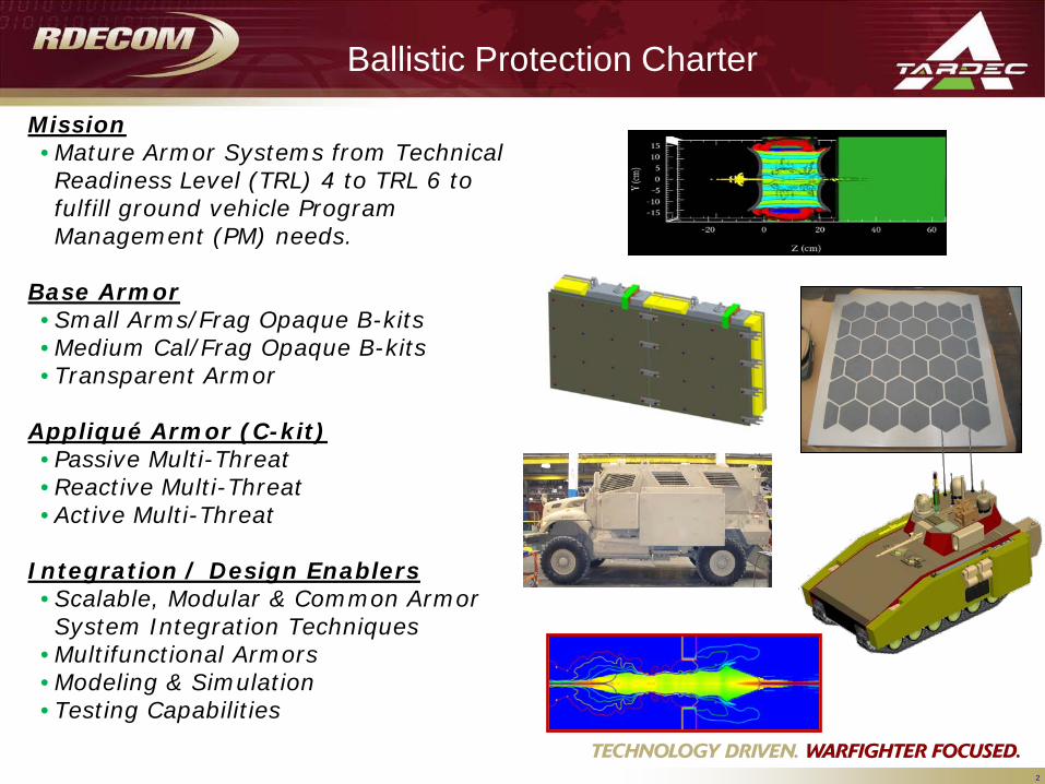
Mission• Mature Armor Systems from Technical Readiness Level (TRL) 4 to TRL 6 to fulfill ground vehicle Program Management (PM) needs.
Base Armor• Small Arms/Frag Opaque B-kits• Medium Cal/Frag Opaque B-kits• Transparent Armor
Appliqué Armor (C-kit)• Passive Multi-Threat• Reactive Multi-Threat• Active Multi-Threat
Integration / Design Enablers• Scalable, Modular & Common Armor System Integration Techniques
• Multifunctional Armors• Modeling & Simulation• Testing Capabilities
Ballistic Protection Charter
3
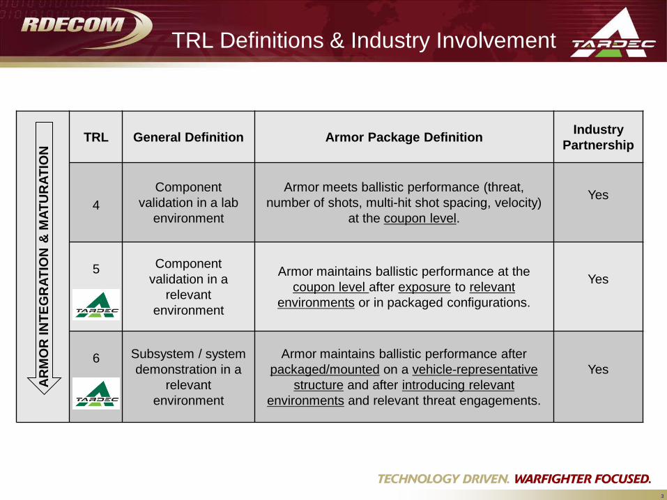
TRL Definitions & Industry InvolvementA
RM
OR
INTE
GR
ATIO
N&
MAT
UR
ATIO
N
TRL General Definition Armor Package Definition Industry Partnership
4Component
validation in a lab environment
Armor meets ballistic performance (threat, number of shots, multi-hit shot spacing, velocity)
at the coupon level.
Yes
5 Component validation in a
relevant environment
Armor maintains ballistic performance at the coupon level after exposure to relevant
environments or in packaged configurations.
Yes
6 Subsystem / system demonstration in a
relevant environment
Armor maintains ballistic performance after packaged/mounted on a vehicle-representative
structure and after introducing relevant environments and relevant threat engagements.
Yes

4
MIL-STD 810 & ATPD 2352 Tests
The following tests have been identified as potential teststhat could be required for maturation of a new armordesign. The tests required will be dependent on thematerials and uniqueness of the armor design.
MIL-STD 810• Heat Loading• Cold Loading• Thermal Cycling• Contamination by Fluids• Solar Radiation• Rain• Humidity• Salt Fog• Sand & Dust• Acidic Atmosphere• Vibration• Shock• Fire, Smoke & Toxicity
ATPD 2352 (First Article)• Allowable Defects• Transmittance• Haze• Optical• Chemical• De-icing• Humidity• Abrasion• Sun Exposure• Weathering• Ballistic (@ ambient temp)• Temp (Shock, Low & High)• Rock Strike / Low Impact
5
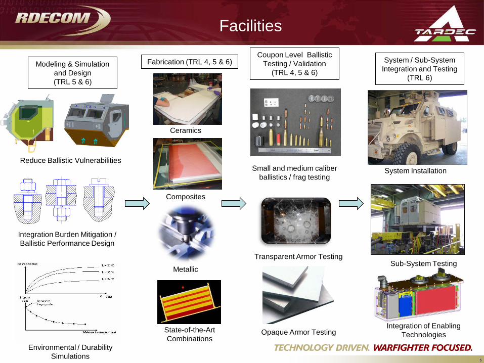
FacilitiesCoupon Level Ballistic
Testing / Validation(TRL 4, 5 & 6)
Small and medium caliber ballistics / frag testing
Opaque Armor Testing
Modeling & Simulation and Design(TRL 5 & 6)
Fabrication (TRL 4, 5 & 6) System / Sub-System Integration and Testing
(TRL 6)
Environmental / Durability Simulations
Integration Burden Mitigation / Ballistic Performance Design
Reduce Ballistic Vulnerabilities
Ceramics
Composites
Metallic
State-of-the-Art Combinations
System Installation
Integration of Enabling Technologies
Sub-System TestingTransparent Armor Testing
6
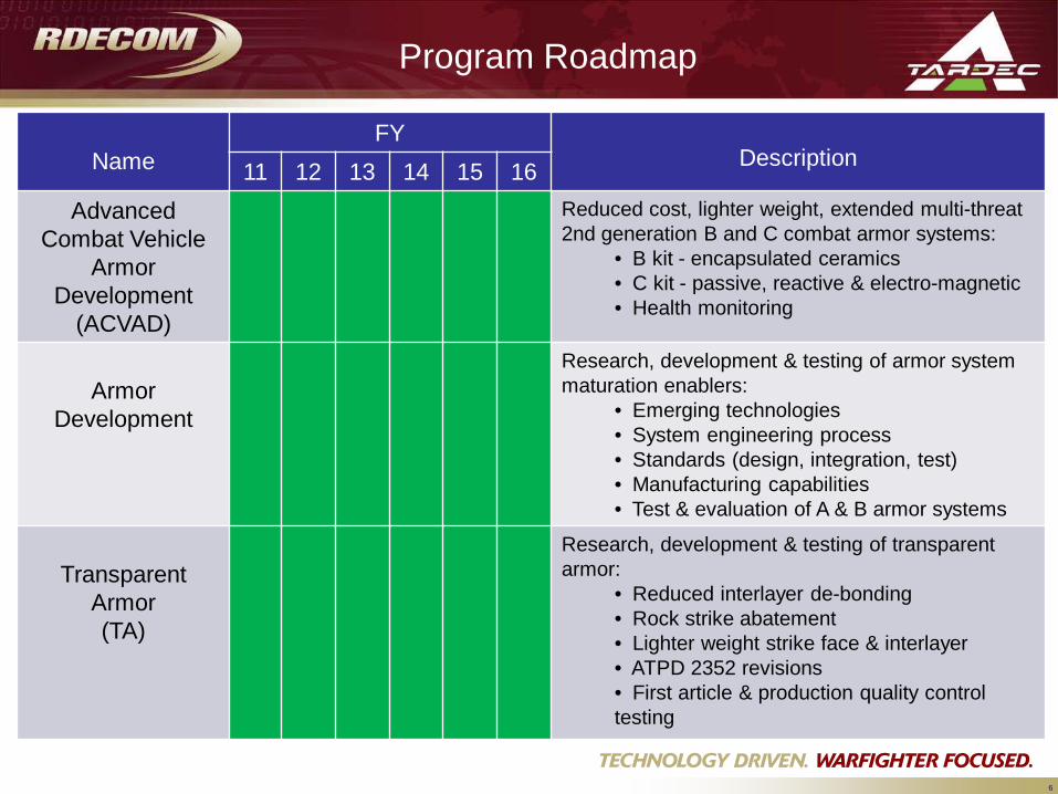
Program Roadmap
NameFY
Description11 12 13 14 15 16Advanced
Combat Vehicle Armor
Development (ACVAD)
Reduced cost, lighter weight, extended multi-threat 2nd generation B and C combat armor systems:
• B kit - encapsulated ceramics• C kit - passive, reactive & electro-magnetic• Health monitoring
Armor Development
Research, development & testing of armor system maturation enablers:
• Emerging technologies• System engineering process• Standards (design, integration, test) • Manufacturing capabilities• Test & evaluation of A & B armor systems
Transparent Armor (TA)
Research, development & testing of transparentarmor:
• Reduced interlayer de-bonding• Rock strike abatement • Lighter weight strike face & interlayer• ATPD 2352 revisions• First article & production quality control testing
7
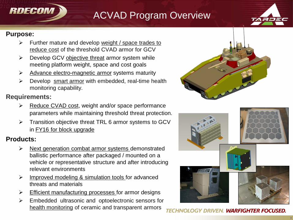
ACVAD Program Overview
Purpose: Further mature and develop weight / space trades to
reduce cost of the threshold CVAD armor for GCV Develop GCV objective threat armor system while
meeting platform weight, space and cost goals Advance electro-magnetic armor systems maturity Develop smart armor with embedded, real-time health
monitoring capability. Requirements:
Reduce CVAD cost, weight and/or space performance parameters while maintaining threshold threat protection.
Transition objective threat TRL 6 armor systems to GCV in FY16 for block upgrade
Products: Next generation combat armor systems demonstrated
ballistic performance after packaged / mounted on a vehicle or representative structure and after introducing relevant environments
Improved modeling & simulation tools for advanced threats and materials
Efficient manufacturing processes for armor designs Embedded ultrasonic and optoelectronic sensors for
health monitoring of ceramic and transparent armors
8
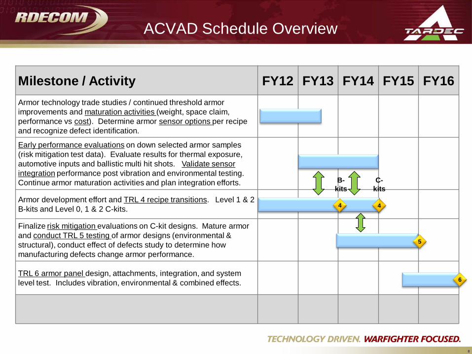
ACVAD Schedule Overview
Milestone / Activity FY12 FY13 FY14 FY15 FY16Armor technology trade studies / continued threshold armor improvements and maturation activities (weight, space claim, performance vs cost). Determine armor sensor options per recipe and recognize defect identification.
Early performance evaluations on down selected armor samples (risk mitigation test data). Evaluate results for thermal exposure, automotive inputs and ballistic multi hit shots. Validate sensor integration performance post vibration and environmental testing. Continue armor maturation activities and plan integration efforts.
Armor development effort and TRL 4 recipe transitions. Level 1 & 2 B-kits and Level 0, 1 & 2 C-kits.
Finalize risk mitigation evaluations on C-kit designs. Mature armor and conduct TRL 5 testing of armor designs (environmental &structural), conduct effect of defects study to determine how manufacturing defects change armor performance.
TRL 6 armor panel design, attachments, integration, and system level test. Includes vibration, environmental & combined effects. 6
5
44
B-kits
C-kits
9
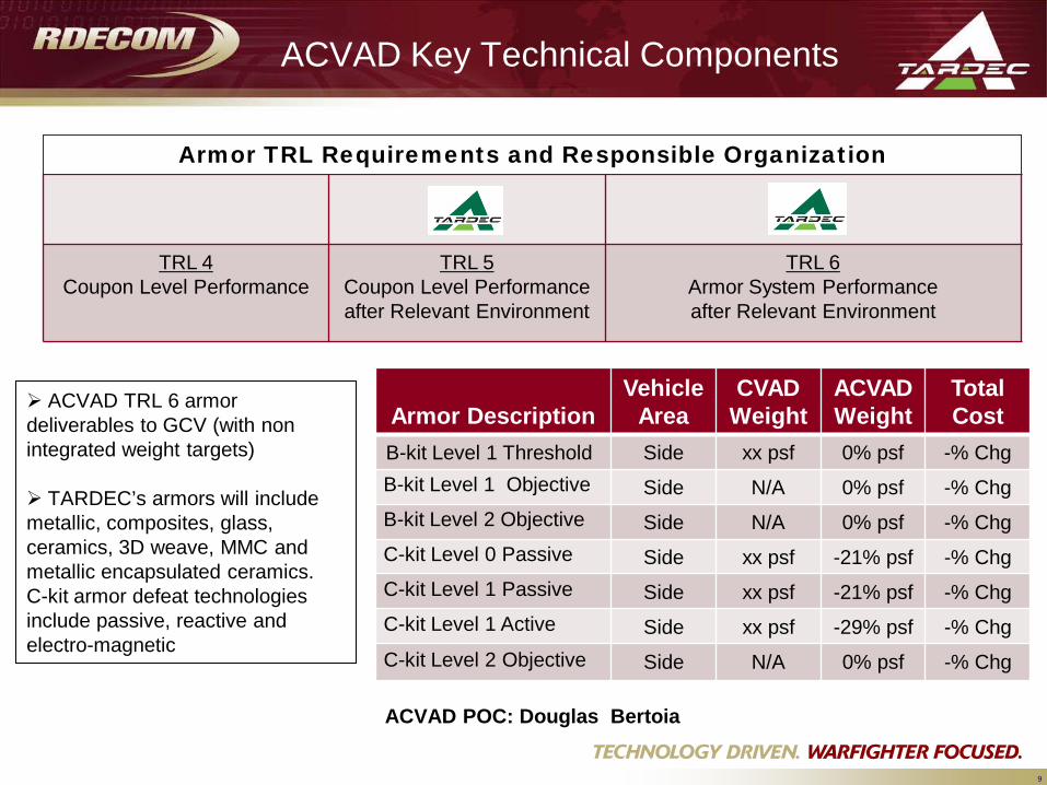
Armor DescriptionVehicle
AreaCVAD
WeightACVAD Weight
TotalCost
B-kit Level 1 Threshold Side xx psf 0% psf -% ChgB-kit Level 1 Objective Side N/A 0% psf -% ChgB-kit Level 2 Objective Side N/A 0% psf -% ChgC-kit Level 0 Passive Side xx psf -21% psf -% ChgC-kit Level 1 Passive Side xx psf -21% psf -% ChgC-kit Level 1 Active Side xx psf -29% psf -% ChgC-kit Level 2 Objective Side N/A 0% psf -% Chg
ACVAD Key Technical Components
TRL 4Coupon Level Performance
TRL 5Coupon Level Performance after Relevant Environment
TRL 6Armor System Performance after Relevant Environment
Armor TRL Requirements and Responsible Organization
ACVAD TRL 6 armor deliverables to GCV (with non integrated weight targets)
TARDEC’s armors will include metallic, composites, glass, ceramics, 3D weave, MMC and metallic encapsulated ceramics. C-kit armor defeat technologies include passive, reactive and electro-magnetic
ACVAD POC: Douglas Bertoia
10
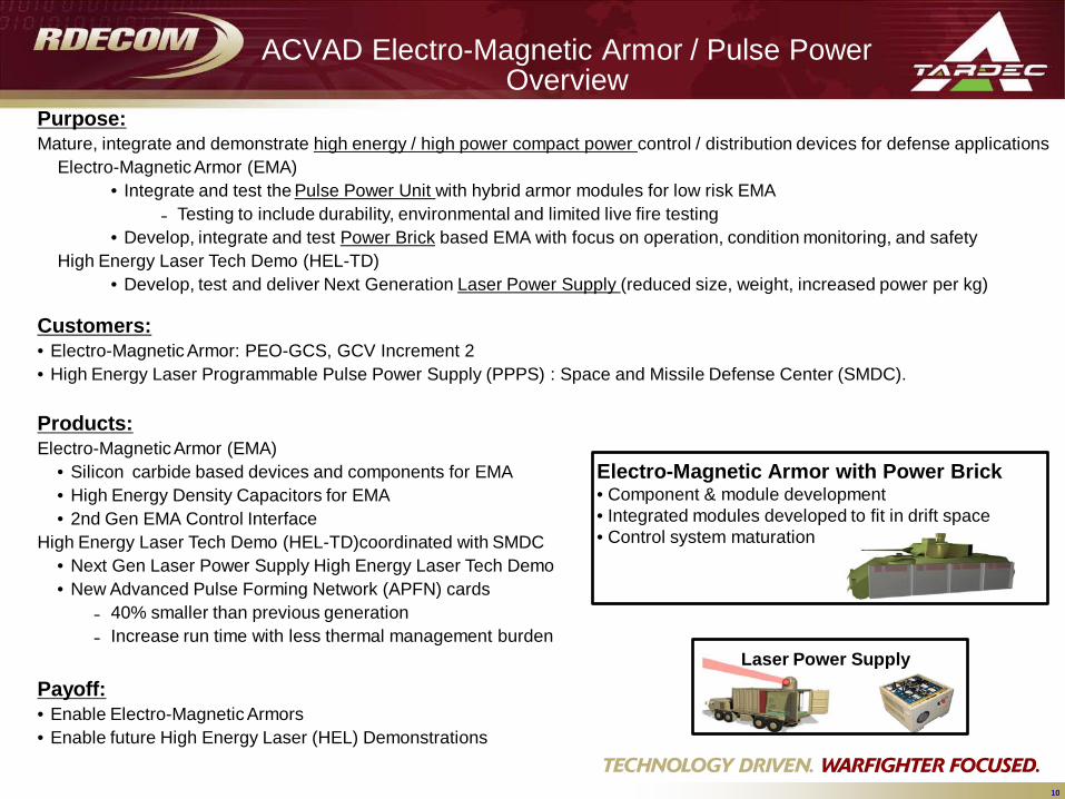
Purpose: Mature, integrate and demonstrate high energy / high power compact power control / distribution devices for defense applications
Electro-Magnetic Armor (EMA)• Integrate and test the Pulse Power Unit with hybrid armor modules for low risk EMA
Testing to include durability, environmental and limited live fire testing• Develop, integrate and test Power Brick based EMA with focus on operation, condition monitoring, and safety
High Energy Laser Tech Demo (HEL-TD) • Develop, test and deliver Next Generation Laser Power Supply (reduced size, weight, increased power per kg)
Customers:• Electro-Magnetic Armor: PEO-GCS, GCV Increment 2 • High Energy Laser Programmable Pulse Power Supply (PPPS) : Space and Missile Defense Center (SMDC).
Products: Electro-Magnetic Armor (EMA)
• Silicon carbide based devices and components for EMA• High Energy Density Capacitors for EMA• 2nd Gen EMA Control Interface
High Energy Laser Tech Demo (HEL-TD)coordinated with SMDC • Next Gen Laser Power Supply High Energy Laser Tech Demo • New Advanced Pulse Forming Network (APFN) cards
40% smaller than previous generation Increase run time with less thermal management burden
Payoff: • Enable Electro-Magnetic Armors • Enable future High Energy Laser (HEL) Demonstrations
10
Electro-Magnetic Armor with Power Brick• Component & module development• Integrated modules developed to fit in drift space• Control system maturation
Laser Power Supply
ACVAD Electro-Magnetic Armor / Pulse Power Overview
11
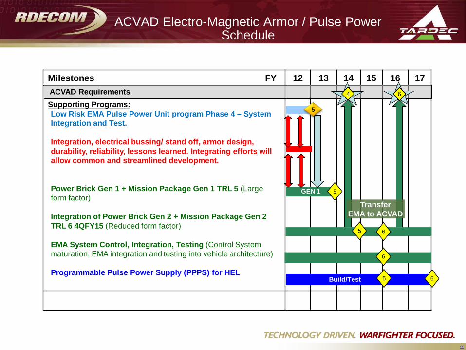
Milestones FY 12 13 14 15 16 17
Supporting Programs:Low Risk EMA Pulse Power Unit program Phase 4 – System Integration and Test.
Integration, electrical bussing/ stand off, armor design, durability, reliability, lessons learned. Integrating efforts will allow common and streamlined development.
Power Brick Gen 1 + Mission Package Gen 1 TRL 5 (Large form factor)
Integration of Power Brick Gen 2 + Mission Package Gen 2 TRL 6 4QFY15 (Reduced form factor)
EMA System Control, Integration, Testing (Control System maturation, EMA integration and testing into vehicle architecture)
Programmable Pulse Power Supply (PPPS) for HEL
6
Build/Test 5
5GEN 1
65
6
5
4 6ACVAD Requirements
TransferEMA to ACVAD
ACVAD Electro-Magnetic Armor / Pulse Power Schedule
12
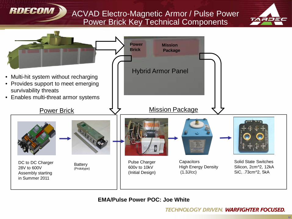
Hybrid Armor Panel
CapacitorsHigh Energy Density(1.3J/cc)
Pulse Charger600v to 10kV(Initial Design)
Battery (Prototype)
DC to DC Charger28V to 600V Assembly startingin Summer 2011
Solid State SwitchesSilicon, 2cm^2, 12kASiC, .73cm^2, 5kA
Power Brick Mission Package
MissionPackage
Power Brick
• Multi-hit system without recharging• Provides support to meet emerging
survivability threats• Enables multi-threat armor systems
ACVAD Electro-Magnetic Armor / Pulse Power Power Brick Key Technical Components
EMA/Pulse Power POC: Joe White
13
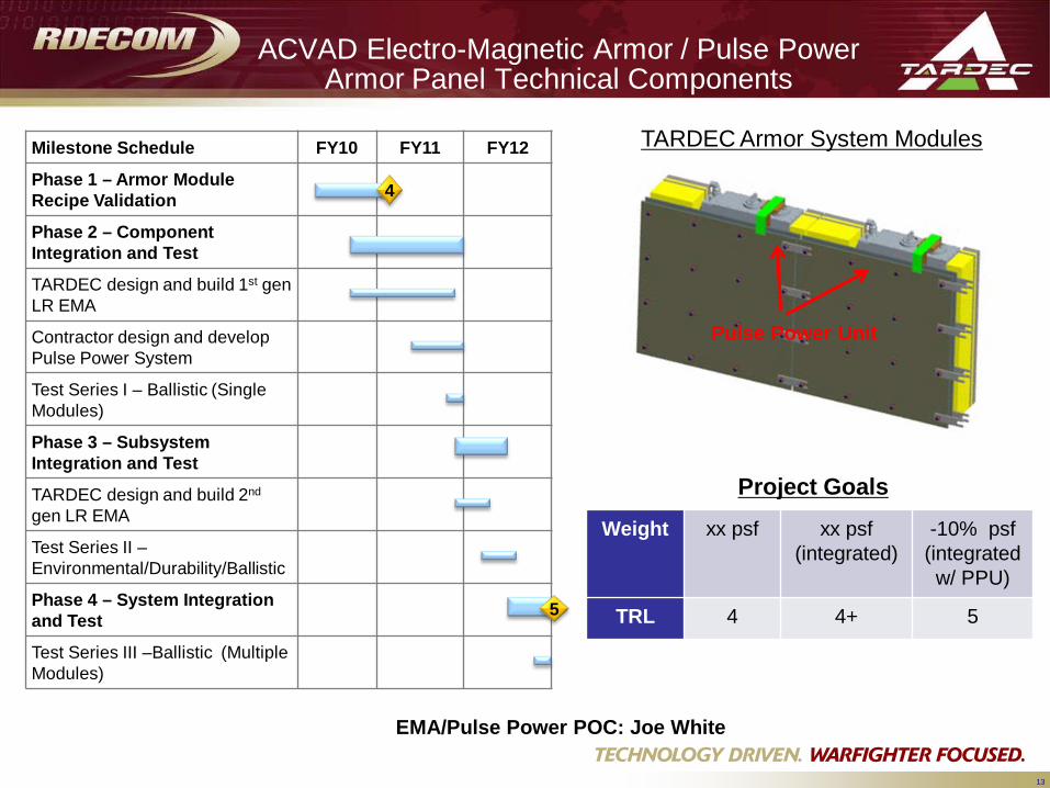
Milestone Schedule FY10 FY11 FY12
Phase 1 – Armor Module Recipe Validation
Phase 2 – ComponentIntegration and Test
TARDEC design and build 1st gen LR EMA
Contractor design and develop Pulse Power System
Test Series I – Ballistic (Single Modules)
Phase 3 – SubsystemIntegration and Test
TARDEC design and build 2nd
gen LR EMA
Test Series II –Environmental/Durability/Ballistic
Phase 4 – System Integration and Test
Test Series III –Ballistic (Multiple Modules)
Pulse Power Unit
5
4
TARDEC Armor System Modules
Project Goals
ACVAD Electro-Magnetic Armor / Pulse Power Armor Panel Technical Components
Weight xx psf xx psf(integrated)
-10% psf(integrated w/ PPU)
TRL 4 4+ 5
EMA/Pulse Power POC: Joe White
14
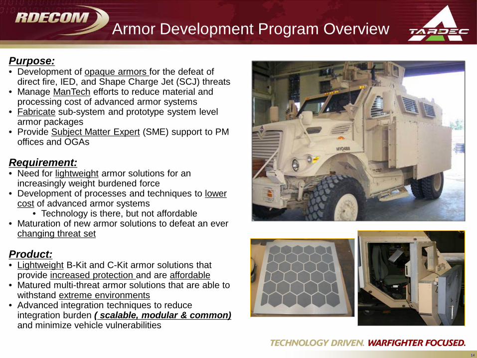
Armor Development Program Overview
Purpose: • Development of opaque armors for the defeat of
direct fire, IED, and Shape Charge Jet (SCJ) threats• Manage ManTech efforts to reduce material and
processing cost of advanced armor systems• Fabricate sub-system and prototype system level
armor packages• Provide Subject Matter Expert (SME) support to PM
offices and OGAs
Requirement:• Need for lightweight armor solutions for an
increasingly weight burdened force• Development of processes and techniques to lower
cost of advanced armor systems• Technology is there, but not affordable
• Maturation of new armor solutions to defeat an ever changing threat set
Product:• Lightweight B-Kit and C-Kit armor solutions that
provide increased protection and are affordable• Matured multi-threat armor solutions that are able to
withstand extreme environments• Advanced integration techniques to reduce
integration burden ( scalable, modular & common) and minimize vehicle vulnerabilities
15
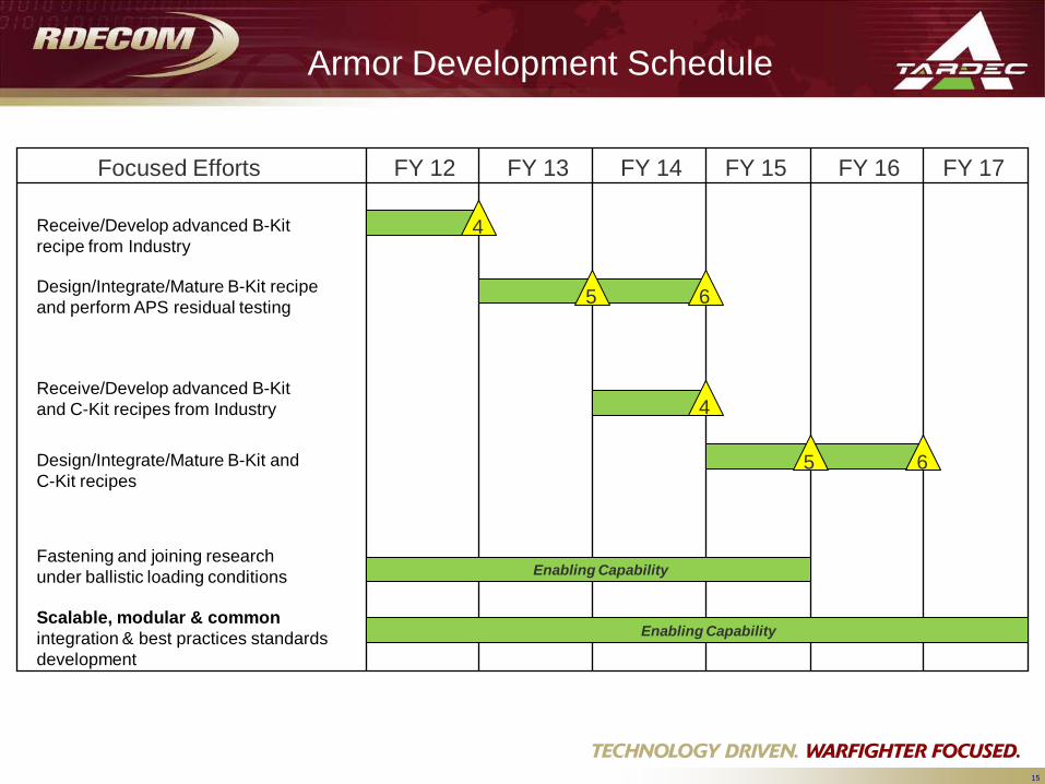
Armor Development Schedule
Focused Efforts FY 12 FY 13 FY 14 FY 15 FY 16 FY 17
Receive/Develop advanced B-Kit recipe from Industry
Design/Integrate/Mature B-Kit recipe and perform APS residual testing
4
5 6
Scalable, modular & common integration & best practices standards development
Fastening and joining research under ballistic loading conditions Enabling Capability
Receive/Develop advanced B-Kit and C-Kit recipes from Industry
Design/Integrate/Mature B-Kit and C-Kit recipes
4
5 6
Enabling Capability
16
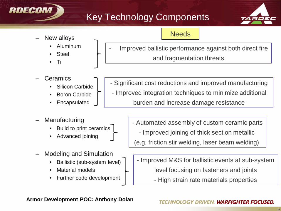
Key Technology Components
– New alloys• Aluminum• Steel• Ti
– Ceramics• Silicon Carbide• Boron Carbide• Encapsulated
– Manufacturing• Build to print ceramics• Advanced joining
– Modeling and Simulation• Ballistic (sub-system level)• Material models• Further code development
- Significant cost reductions and improved manufacturing- Improved integration techniques to minimize additional
burden and increase damage resistance
Needs
- Automated assembly of custom ceramic parts- Improved joining of thick section metallic
(e.g. friction stir welding, laser beam welding)
- Improved M&S for ballistic events at sub-systemlevel focusing on fasteners and joints- High strain rate materials properties
- Improved ballistic performance against both direct fireand fragmentation threats
Armor Development POC: Anthony Dolan
17
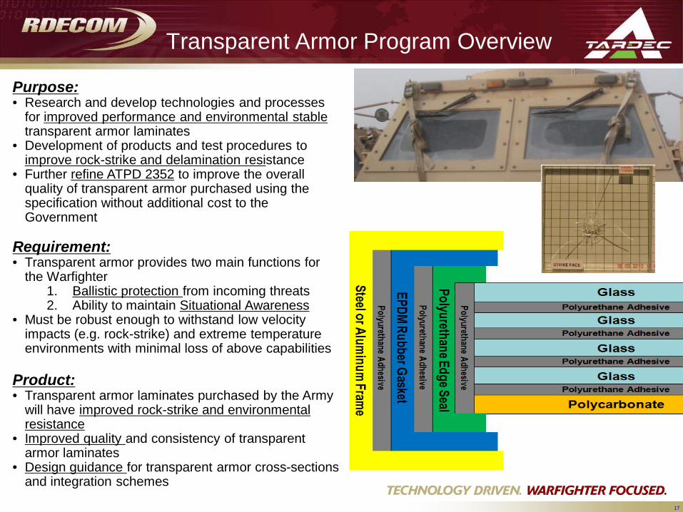
Transparent Armor Program Overview
Purpose: • Research and develop technologies and processes
for improved performance and environmental stable transparent armor laminates
• Development of products and test procedures to improve rock-strike and delamination resistance
• Further refine ATPD 2352 to improve the overall quality of transparent armor purchased using the specification without additional cost to the Government
Requirement:• Transparent armor provides two main functions for
the Warfighter1. Ballistic protection from incoming threats2. Ability to maintain Situational Awareness
• Must be robust enough to withstand low velocity impacts (e.g. rock-strike) and extreme temperature environments with minimal loss of above capabilities
Product:• Transparent armor laminates purchased by the Army
will have improved rock-strike and environmental resistance
• Improved quality and consistency of transparent armor laminates
• Design guidance for transparent armor cross-sections and integration schemes
18
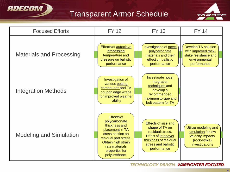
Transparent Armor Schedule
Focused Efforts FY 12 FY 13 FY 14
Materials and Processing Effects of autoclave
processing temperature and
pressure on ballistic performance
Investigation of various potting
compounds and TA coupon edge wraps
for improved weather -ability
Modeling and Simulation
Integration Methods
Effects of polycarbonate thickness and
placement in TA cross-section on
residual part stress. Obtain high strain
rate materials properties for polyurethane.
Investigation of novel polycarbonate
materials and their effect on ballistic
performance
Investigate novel integration
techniques and develop a
recommended maximum torque and
bolt pattern for TA
Effects of size and shape of TA on residual stress.
Effect of interlayer thickness of residual stress and ballistic
performance
Develop TA solution with improved rock-strike resistance and
environmental performance
Utilize modeling and simulation for low velocity impacts
(rock-strike) investigations
19
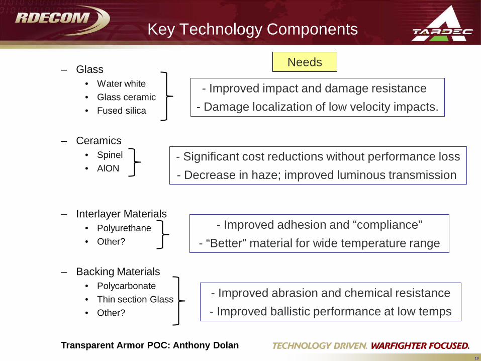
Key Technology Components
– Glass• Water white• Glass ceramic• Fused silica
– Ceramics• Spinel• AlON
– Interlayer Materials• Polyurethane• Other?
– Backing Materials• Polycarbonate• Thin section Glass• Other?
- Improved impact and damage resistance - Damage localization of low velocity impacts.
- Significant cost reductions without performance loss- Decrease in haze; improved luminous transmission
- Improved adhesion and “compliance”- “Better” material for wide temperature range
- Improved abrasion and chemical resistance- Improved ballistic performance at low temps
Needs
Transparent Armor POC: Anthony Dolan
21
Conclusion
• Who we are.• What our mission is.• How we plan.• What we are investing in.• When we plan to work these efforts.• Ideas on how you can help us help the Warfighter.
This is the first of an annual event…..It may not be perfect, so we want the feed back to help us help you.
UNCLASSIFIED
UNCLASSIFIED