Embed Size (px)
Citation preview

BALLAST WATER TREATMENT SYSTEM
Installation and Commissioning
Ref: BS_FX_02 rev ARelease date : March 2014
BIO-UV FRANCEEmail: [email protected]: +33(0)499.133.911

Page 2 BS_FX_02 rev A
Installation and Commissioning
Pages intentionally left blank

BS_FX_02 rev A Page 3
Installation and Commissioning
Foreword
1. Foreword ................................................................................................................................ 71.1. Scope of the Manual ..................................................................................................................................... 71.2. Document Symbols....................................................................................................................................... 81.3. Abbreviations .................................................................................................................................................. 81.4. Standard measuring units........................................................................................................................... 9
2. Legal Information............................................................................................................. 102.1. Certificates...................................................................................................................................................... 102.2. Notice of Liability and warranty.............................................................................................................. 102.3. Trademarks..................................................................................................................................................... 112.4. Graphics........................................................................................................................................................... 112.5. Copyright ® 2013 by BIO-UV.................................................................................................................... 11
3. Contacts and Technical Service................................................................................... 12
Precautions and Safety Instructions
4. Warnings and Precautions ............................................................................................ 134.1. Safety Precautions ....................................................................................................................................... 13
4.1.1. Information supplied to the operator ......................................................................................................134.1.2. Filter ......................................................................................................................................................................144.1.3. UV Reactors ........................................................................................................................................................144.1.4. Electrical components ....................................................................................................................................15
4.2. Environmental impact................................................................................................................................ 15
5. Symbols and System Labels ......................................................................................... 165.1. Symbols ........................................................................................................................................................... 165.2. Labels................................................................................................................................................................ 17
5.2.1. System Identification Plate ...........................................................................................................................175.2.2. Identification of sub-assemblies .................................................................................................................17

Page 4 BS_FX_02 rev A
Installation and Commissioning
Installation
6. General Recommendations for installation............................................................. 186.1. Prerequisites.................................................................................................................................................. 186.2. Required tools............................................................................................................................................... 19
7. Mechanical installation ................................................................................................... 207.1. Mounting of the Filter................................................................................................................................ 20
7.1.1. Filter’s body ........................................................................................................................................................ 217.1.2. Valves ................................................................................................................................................................... 217.1.3. Backwash pump ............................................................................................................................................... 22
7.2. Overview of UV Assembly ........................................................................................................................ 227.3. Mounting of the By-Pass Valves ............................................................................................................. 237.4. UV Assembly.................................................................................................................................................. 25
7.4.1. Manifold .............................................................................................................................................................. 257.4.2. Flange Mounting ............................................................................................................................................. 267.4.3. UV reactors ......................................................................................................................................................... 267.4.4. Sensors ................................................................................................................................................................. 287.4.5. Draining pump ................................................................................................................................................. 287.4.6. Leaking test on the reactors ........................................................................................................................ 29
7.5. Flow meter Installation.............................................................................................................................. 307.5.1. Mounting location ........................................................................................................................................... 307.5.2. Foundations and supports ........................................................................................................................... 307.5.3. Inlet and outlet runs ....................................................................................................................................... 317.5.4. Vertical pipes ..................................................................................................................................................... 317.5.5. Partially Filled Pipes ........................................................................................................................................ 317.5.6. Vertical orientation .......................................................................................................................................... 327.5.7. Horizontal orientation .................................................................................................................................... 32
7.6. Installation of sampling ports ................................................................................................................. 33
8. Electrical installation ........................................................................................................ 348.1. General Description.................................................................................................................................... 34
8.1.1. Electrical Main Wiring ..................................................................................................................................... 348.1.2. Cabinets Location ............................................................................................................................................ 358.1.3. Identification of the cabinets ...................................................................................................................... 368.1.4. Cables list ............................................................................................................................................................ 378.1.5. References for wiring diagrams .................................................................................................................. 38
8.2. Main Wiring from/to Vessel ..................................................................................................................... 398.2.1. Power supply (all cabinets) .......................................................................................................................... 398.2.2. Wiring for remote control (vessel switchboard) ................................................................................... 408.2.3. Wiring 24Vdc power supply ......................................................................................................................... 41
8.3. Lamp cable wiring....................................................................................................................................... 428.3.1. Connection of lamp cable on reactor side .............................................................................................. 428.3.2. Connection of lamp cable on power cabinet side ............................................................................... 43
8.4. Wiring of Profibus cable between cabinets ....................................................................................... 448.4.1. Connector wiring in control cabinet A0 and power cabinet A1 ..................................................... 45

BS_FX_02 rev A Page 5
Installation and Commissioning
8.4.2. Profibus wiring between power cabinets ...............................................................................................468.5. Wiring of Control Cabinet ......................................................................................................................... 47
8.5.1. Sensors wiring (UV, temperature and flowmeter) ...............................................................................488.5.2. Wiring of pneumatic valves for operations ............................................................................................498.5.3. Pumps and motors wiring ............................................................................................................................49
9. Checking of the BWTS installation ............................................................................. 509.1. Mechanical Checking.................................................................................................................................. 50
9.1.1. General checking .............................................................................................................................................509.1.2. Filter checking ...................................................................................................................................................519.1.3. UV assembly checking ....................................................................................................................................52
9.2. Electrical checking ....................................................................................................................................... 54
10. Instructions for piping verification .......................................................................... 56
Commissioning
11. General Recommendations for Commissioning ................................................ 5711.1. Documentation .......................................................................................................................................... 5711.2. Required tools............................................................................................................................................. 58
12. Power, Water and Air supply ..................................................................................... 5912.1. Air / Oil supply for valves ........................................................................................................................ 59
12.1.1. Air supply (pneumatic valves) ...................................................................................................................5912.1.2. Oil supply (hydraulic valves) ......................................................................................................................59
12.2. Fresh Water Supply ................................................................................................................................... 5912.3. Power supply............................................................................................................................................... 60
12.3.1. General power supply ..................................................................................................................................6012.3.2. Power cabinets ...............................................................................................................................................6012.3.3. Control cabinet ...............................................................................................................................................61
13. Test in MANUAL Mode................................................................................................. 6313.1. Select MANUAL mode.............................................................................................................................. 6313.2. Filter module check .................................................................................................................................. 65
13.2.1. Filter Selection ................................................................................................................................................6513.2.2. Check Filter settings .....................................................................................................................................6513.2.3. Check filter valves ..........................................................................................................................................6613.2.4. Check the backwash pump (P101) ..........................................................................................................6713.2.5. Check the motor (M101) .............................................................................................................................67
13.3. UV assembly checking ............................................................................................................................. 68

Page 6 BS_FX_02 rev A
Installation and Commissioning
13.3.1. Check UV Settings ......................................................................................................................................... 6813.3.2. Check UV valves ............................................................................................................................................. 7013.3.3. Check the draining pump (P001) ............................................................................................................. 7013.3.4. Check UV lamps ............................................................................................................................................. 71
13.4. Check other factory Setting................................................................................................................... 7313.4.1. Check Measured Parameters ..................................................................................................................... 7313.4.2. Check Mechanical Response ..................................................................................................................... 7313.4.3. Check Date and Time ................................................................................................................................... 73
14. Set washing parameters............................................................................................... 7414.1. Filter cleaning............................................................................................................................................. 74
14.1.1. Filling of the Filters ....................................................................................................................................... 7414.1.2. Emptying The Filter (Manual Mode) ....................................................................................................... 75
14.2. UV cleaning ................................................................................................................................................. 7514.2.1. Filling Reactors and Manifolds (Manual mode) .................................................................................. 7514.2.2. Emptying Reactors and Manifolds (Manual mode) ........................................................................... 76
14.3. Setting Washing Parameters on PLC.................................................................................................. 76
15. Test In Automatic Mode ............................................................................................... 7715.1. Test of the flow meter ............................................................................................................................. 7715.2. Select AUTO mode.................................................................................................................................... 7815.3. Test of automatic ballasting.................................................................................................................. 79
15.3.1. Ballast water management for Ballasting process ............................................................................ 7915.3.2. Verify stable operation ................................................................................................................................ 8015.3.3. Force Backwash .............................................................................................................................................. 8115.3.4. Test Backwash by the Differential ........................................................................................................... 8115.3.5. Force draining/rinsing ................................................................................................................................. 81
15.4. Test of automatic deballasting............................................................................................................. 8215.4.1. Ballast water management for deballasting process ....................................................................... 8215.4.2. Verify stable operation ................................................................................................................................ 83
15.5. Test of automatic cleaning .................................................................................................................... 8415.5.1. When the end cycle cleaning is finished: .............................................................................................. 85
16. Operational Checks........................................................................................................ 8616.1. Circulation with BWTS on the line....................................................................................................... 8616.2. Stripping operation.................................................................................................................................. 8616.3. Check the sampling valves .................................................................................................................... 8716.4. First start of archiving.............................................................................................................................. 87

BS_FX_02 rev A Page 7
ForewordForeword
Fore
wor
d
Foreword
1. Foreword
1.1. Scope of the Manual
The BIO-SEA® notice contains instructions and information about BIO-SEA® systems based on thespecifications delivered by BIO-UV company for the proper intended uses.
This notice makes references to the technical manuals of the sub-assemblies (edited by the manufacturers),which are attached as appendix of this proper notice. Annexes also contain references to your specific BIO-SEA® system as needed, depending on your system model and on board configuration.
BIO-UV recommends you to carefully read this notice before attempting to operate or to performmaintenance on BIO-SEA® system.
Non compliance with the information contained in this notice compromises the safety features and correctfunctioning of your BIO-SEA® system.
General characteristics are guaranteed by BIO-UV under the following conditions:
Read carefully the operating instructions before attempting to operate the system.
Always operate with full knowledge and appreciation of BIO-SEA® BWTS warnings and alarms.
Always refer to labeling and instructions in order to avoid compromising BWTS integrity.

Page 8 BS_FX_02 rev A
ForewordForeword
1.2. Document Symbols
To alert the operator of potentially hazardous conditions, symbols described in this chapter are providedwherever necessary throughout the notice.
1.3. Abbreviations
Emphasizes information that can be helpful to the operator before, during or after a specific operational function.
Emphasizes information that must be followed to avoid possible damage to the system.
Emphasizes information that must be followed to avoid hazard to either the operator or the environment, or both.
Emphasizes important information that must be followed to avoid environmental impact or exposure to potentially infectious material.
Table 1: Abbreviations
Definition Definition
BW Ballast Water IMO International Maritime Organization
BWTS Ballast Water Treatment System MEPCMarine Environment Protection Committee
D-2 IMO Discharge Standard for Ballast Water MMC Multimedia Card
EPD Empty Pipe Detection NC Normally Closed (for valves)
EMC Electromagnetic Compatibility NO Normally Open (for valves)
G2Guidelines for Ballast Water Sampling; IMO resolution MEPC.173(58)
PID Piping and Instrumentation Diagram
G8Guidelines for approval of Ballast Water Management Systems ; IMO resolution MEPC.174(58)
PLC Programmable Logic Controller
HMI Human Machine Interface TRC Treatment Rate Capacity

BS_FX_02 rev A Page 9
ForewordForeword
Fore
wor
d
1.4. Standard measuring units
Table 2: Measuring unit list
Measuring type Name Abbreviation
DimensionMillimeter mm
Inch "
Volume Liter L
Flow rate Cubic meter per hour m3/h
Pressure Bar bar
Weight Kilogram kg
Temperature Celsius degree °C
Electric voltageVolt V
Volt Direct Current VDC
Electric intensity Ampere A
Electric powerKilowatt kW
Watt W
Electric frenquency Hertz Hz
UV intensity Watt per square meter W/m2

Page 10 BS_FX_02 rev A
ForewordLegal Information
2. Legal Information
2.1. Certificates
The BIO-SEA® Ballast Water Treatment System is Type Approved according to IMO Resolution MEPC.174(58)“Guidelines for approval of Ballast Water Management Systems (G8)”, contained in the InternationalConvention for the Control and Management of Ships’ Ballast Water and Sediments (2004).
The statutory Type Approval Certificate is delivered as part of the system documentation.
The BIO-SEA® system is approved according to Rules for Classification of Steel Ships.
Depending on the Classification Society, it can be a general design approval, a type approval or a shipspecific approval. The approval documents are delivered as part of the technical documentation.
2.2. Notice of Liability and warranty
The information in this notice is distributed on an "As Is" basis, without warranty.
While every precaution has been taken in the preparation of this notice, BIO-UV will not assume any liabilityto any persons or entities with respect to loss or damage, caused or alleged to be caused directly orindirectly by not following the instructions contained in this document, or by using the BIO-SEA® systemdescribed herein in a manner inconsistent with our product labeling.
The duration of warranty is stipulated in the Sales and Service Conditions associated with the purchase ofthe BIO-SEA® BWTS. To validate the warranty, ensure the following is fulfilled:
The BWTS has been installed and commissioned as instructed in the BIO-SEA® manual (see Installation and Commissioning book BS_FX_02).
The BWTS is operated as instructed in the BIO-SEA® manual (see Operation book BS_FX_03).
BIO-UV reserves the right to modify the technical data enclosed without prior notice

BS_FX_02 rev A Page 11
ForewordLegal Information
Fore
wor
d
Service is done according to BIO-UV recommendations and proper tools are used when maintenance or troubleshooting operations are performed.
Only spare parts supplied by BIO-UV or a local representative can be used, unless they have been expressly specified in the BIO-SEA® manual .
No changes or modifications to the equipment are permitted without express authorization from the manufacturer or his representative.
The electrical installation must adhere to national or international regulations.
2.3. Trademarks
BIO-SEA® is registered trademark of BIO-UV.
Other product names mentioned within this publication may be trademarks or registered trademarks oftheir respective owners.
2.4. Graphics
All graphics including screens, printouts and photographs are for illustration purposes only and are notcontractual.
2.5. Copyright ® 2013 by BIO-UV
All rights reserved. No part of this notice may be reproduced or transmitted in any form or by any means,electronic, mechanical, photocopying, recording, or otherwise, without the prior written permission of BIO-UV.
Email: [email protected]
You should always note and communicate the serial numbers of your unit when requesting service assistance or ordering spare parts.
Page 12 BS_FX_02 rev A
ForewordContacts and Technical Service
3. Contacts and Technical Service
850 Avenue Louis Médard
34400 Lunel Cedex
FRANCE
Tel: +33(0) 499 133 911
Fax: +33(0) 499 133 919
Email: [email protected] or [email protected]
If you have any doubt or if you need any further technical information, please contact your local BIO-UVrepresentative.

BS_FX_02 rev A Page 13
Precautions and Safety InstructionsWarnings and Precautions
Prec
auti
ons
and
Safe
ty In
stru
ctio
ns
Precautions and Safety Instructions
4. Warnings and Precautions
4.1. Safety Precautions
The design of the BIO-SEA® BWTS is intended for treatment of ballast water only.
The BIO-SEA® BWTS should not be installed in hazardous area.
Easy access for safe maintenance operations of all the components of the system must be respected.
Failure to comply with the conditions of use described in the present notice will be considered as improperuse. In this case BIO-UV can not guarantee this product in terms of security and performance.
4.1.1. Information supplied to the operator
In order to ensure the correct handling of the BIO-SEA® BWTS during installation, commissioning,operation and maintenance, the following information should be supplied to the crew member in charge:
all the instructions for installing and operating the BWTS
the information related to prevention of accidents according to local or maritime regulations,
the list of equipments and specific tools needed for hazardous operations,
the defined responsibilities for each activity (installation, maintenance and servicing),
the location and identification of the safety labeling.
BIO-SEA® system design and construction comply with latest status of art for water treatment technology and with the general safety requirements, in accordance with Rules for Classification of Steel Ships.
Nevertheless an improper use may cause operator injuries or severe damages to the BWTS equipment.
The BWTS instructions should be integrated in the crew instructions regarding Ballast Water Management and Equipment servicing, including oversight and reporting obligations.
Page 14 BS_FX_02 rev A
Precautions and Safety InstructionsWarnings and Precautions
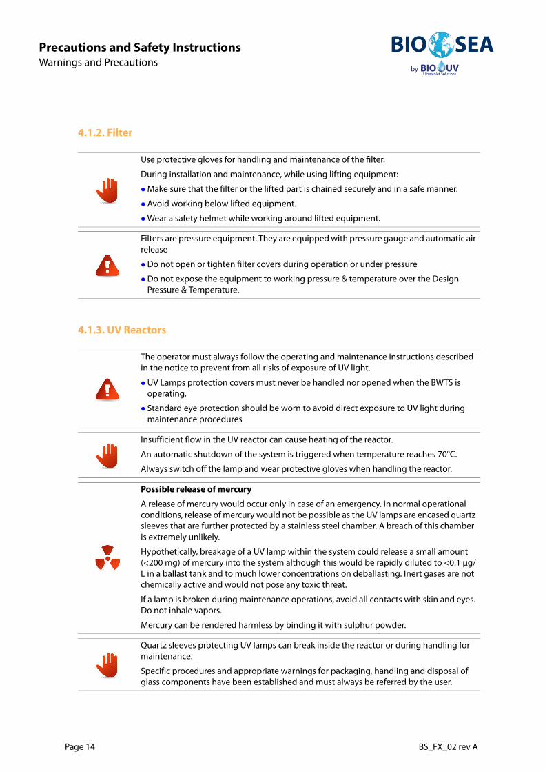
4.1.2. Filter
4.1.3. UV Reactors
Use protective gloves for handling and maintenance of the filter.
During installation and maintenance, while using lifting equipment:
Make sure that the filter or the lifted part is chained securely and in a safe manner.
Avoid working below lifted equipment.
Wear a safety helmet while working around lifted equipment.
Filters are pressure equipment. They are equipped with pressure gauge and automatic air release
Do not open or tighten filter covers during operation or under pressure
Do not expose the equipment to working pressure & temperature over the Design Pressure & Temperature.
The operator must always follow the operating and maintenance instructions described in the notice to prevent from all risks of exposure of UV light.
UV Lamps protection covers must never be handled nor opened when the BWTS is operating.
Standard eye protection should be worn to avoid direct exposure to UV light during maintenance procedures
Insufficient flow in the UV reactor can cause heating of the reactor.
An automatic shutdown of the system is triggered when temperature reaches 70°C.
Always switch off the lamp and wear protective gloves when handling the reactor.
Possible release of mercury
A release of mercury would occur only in case of an emergency. In normal operational conditions, release of mercury would not be possible as the UV lamps are encased quartz sleeves that are further protected by a stainless steel chamber. A breach of this chamber is extremely unlikely.
Hypothetically, breakage of a UV lamp within the system could release a small amount (<200 mg) of mercury into the system although this would be rapidly diluted to <0.1 μg/L in a ballast tank and to much lower concentrations on deballasting. Inert gases are not chemically active and would not pose any toxic threat.
If a lamp is broken during maintenance operations, avoid all contacts with skin and eyes. Do not inhale vapors.
Mercury can be rendered harmless by binding it with sulphur powder.
Quartz sleeves protecting UV lamps can break inside the reactor or during handling for maintenance.
Specific procedures and appropriate warnings for packaging, handling and disposal of glass components have been established and must always be referred by the user.
BS_FX_02 rev A Page 15
Precautions and Safety InstructionsWarnings and Precautions
Prec
auti
ons
and
Safe
ty In
stru
ctio
ns
4.1.4. Electrical components
Always switch off general power circuit before any intervention on one of the cabinets or on connection boxes of the lamps on the reactors.
The operation area must be secured before intervention.
Only approved personnel should operate on the supply cabinets.
4.2. Environmental impact
BIO-SEA® BWTS does not use chemicals nor generate by-products.
There is no risk of:
handling or storage of chemical products
variation of the corrosivity of the treated water
release of substances into the environment.
Operator injury may occur from an electric shock.
Disposable used accessories and consumables must be collected by specialized structures for elimination and recycling of this kind of material according to the local legislation.

Page 16 BS_FX_02 rev A
Precautions and Safety InstructionsSymbols and System Labels
5. Symbols and System Labels
5.1. Symbols
The following symbols can be found on the components of the BIO-SEA® System.
Switch off position Switch on position
Alternating current Packaging recycling mark
Caution, heat source Caution, moving mechanism
Caution, risk of electric shock
Warning, Caution
Never watching when light ONU.V. rays dangerous for eyes

BS_FX_02 rev A Page 17
Precautions and Safety InstructionsSymbols and System Labels
Prec
auti
ons
and
Safe
ty In
stru
ctio
ns
5.2. Labels
5.2.1. System Identification Plate
In accordance with BIO-SEA® Type Approval certificate, each Ballast Water Treatment System is markedwith a engraved plate located on the control cabinet, including the Mark of conformity (as per French RulesArticle 310-1.07) 0062/MMF/XX where XX are the last two digits of year of manufacturing.
Figure 1: System identification plate
5.2.2. Identification of sub-assemblies
Each sub-assembly is marked with the manufacturer plate
Cabinets
Reactors
Filter
Flowmeter
Pumps
Valves
.
Fixed on the control cabinet

Page 18 BS_FX_02 rev A
InstallationGeneral Recommendations for installation
Installation
6. General Recommendations for installation
6.1. Prerequisites
The installation of BIO-SEA® BWTS should be prepared taking into account the following aspects:
Dimensions and Weight of the system
Cabinets location and the maximum cables lengths
Service areas
Operating Pressure and global Pressure Loss
Freshwater Supply for Rinsing Filter and UV Reactors
Compressed Air or Oil Supply for Automatic Valve Actuators
Piping arrangement will have to consider:
Permanent water load in the system
Prevention of Corrosion
Prevention of Cavitation
General By-Pass of the system
Flow meter location on piping
Location of Ballast Water Sampling ports
For more details, please refer to «Specifications and Integration Guidelines» book (BS_FX_01), as well as to specific drawings of the system (technical binder).

BS_FX_02 rev A Page 19
InstallationGeneral Recommendations for installation
Inst
alla
tion
6.2. Required tools
BIO-SEA® system is delivered with a tool kit that can be used for installation and commissioning of BWTS.
However, tools below could be standard and not be part of the tool kit.
Table 3: Standard tool kit (OUT009426) supplied with the system
Designation Use for BIO-SEA® BWTS Installation Reference
Screw drivers for WAGO terminal Electrical installation OUT009229
Quartz sleeve pusherSpecific tools for quartz operations
OUT009228
Quartz sleeve guiding tool OUT009227
For description of this kit, refer to corresponding data sheet in Annex.
Table 4: Standard Tools needed (not delivered with the system)
Specifics Tools Use for BIO-SEA® BWTS Installation Reference
Multimeter Electrical checks Standard
Screw Driver For ElectricalTerminals Connections
Electrical installation Flat (thin) and Philips
Bit Torx Connection of subcomponents (valves, flow meter...)
Standard
Allen keys Standard metric

Page 20 BS_FX_02 rev A
InstallationMechanical installation
7. Mechanical installation
7.1. Mounting of the Filter
Figure 2: Mounting of valves on the filter
Please refer to the Filtrex manual.
Be careful to leave the working area for maintenance of the filters and a lifting point:
Height: 2 m
Maintenance area: 2 m2 around the filter
1- Inlet outlet automatic valves, disk normally closed (cf PID: Y101, Y102, Y104)
(Y104 valve on a backwash pump)
2- Automatic valve for bypass, disk normally open (cf PID: Y103)
1
1
2

BS_FX_02 rev A Page 21
InstallationMechanical installation
Inst
alla
tion
7.1.1. Filter’s body
Proceed to a visual verification within the filter:
Open the filter cover on the filter body,
Check that the pre-filter, filter basket and scanner are properly assembled.
Position the filter’s body on its support and mount the corresponding inlet and outlet pipes (see arrows on the filter’s inlet and outlet to know the normal flow direction)
7.1.2. Valves
Assemble automatic valves with (butterfly) disk open
Check manually the disc of each butterfly valves can fully open or close.
Position the disc of the valve following the normal rest position of the valve (open or close),
Mount again each actuator of the valves
Do not step on the valves.
The opening way of the actuators of the valves is “counterclockwise”.
Table 5: Identification of Valves and Pumps for filter module
Valve nr Rest pos. DescriptionPump or motor nr
Description
Y101 NC Filter inlet valve / entry valve P101 Filter backwash pump
Y102 NC Filter outlet valve / exit valve M101 Filter backwash motor
Y103 NO Filter by-pass valve
Y104 NC Backwash pump outlet valve
Y105 NC Filter Fresh water filling valve
Y106 NC Sea water drain valve
Y107 NC Filter vent valve
NC = Normally closed valve / NO = Normally open valve / - = Not applicable (e.g. Manual valve)
Page 22 BS_FX_02 rev A
InstallationMechanical installation
Check that the valves actuators are tight.
Connect the valve to compressed air (if pneumatic valve) or to oil supply (if hydraulic valve).
Check that the valves are supplied with air and with the right pressure (5 to 8 bars).
Let the manual valves in the following states:
Manual valves of the differential pressure gauge are open.
Manual valve of the Automatic air drainer is open.
7.1.3. Backwash pump
The backwash suction pump inlet has to be connected to the flushing outlet of the filter.
7.2. Overview of UV Assembly
Be careful to leave the working area for maintenance as shown in Figure 7: Minimum working area, page 27.
Check that the Manifold is perpendicular to the floor.
The reactors must be installed parallel to the floor (Tolerance +/-5°).
The reactors have to be installed with the supports for UV sensor pointing upwards.

BS_FX_02 rev A Page 23
InstallationMechanical installation
Inst
alla
tion
Figure 3: Reactors assembly overview
7.3. Mounting of the By-Pass Valves
Assemble automatic valves with butterfly disk open.
Check manually the disc of each butterfly valves can fully open or close.
1- The Automatic vent (air valve) is on the highest position with manual valve for security.
2- Temperature sensor and UV sensor must be installed on the highest UV reactor.
3- Position of manual valves for reactors insulation
4- Inlet, outlet automatic valves, butterfly normally closed (cf PID Y103, Y7)
5- Automatic valve for bypass, butterfly normally open (see PID Y101, Y102, Y104, Y5, Y6, Y8: 15.3. Test of automatic ballasting, Chapter 6 page 79)
6- Fresh Water drain
Please refer to the Installation notice of the Valves supplier.
Do not step on the valves.
1
2
5
4
4
3
6

Page 24 BS_FX_02 rev A
InstallationMechanical installation
Position the disc of the valve following the normal rest position of the valve (open or close),
Mount again each actuator of the valves
Check that the valves actuators are tight.
Connect the valve to compressed air (if pneumatic valve) or to oil supply (if hydraulic valve).
Check that the valves are supplied with air and with the right pressure (5 to 8 bars).
The opening way of the actuators of the valves is “counterclockwise”.
Table 6: Identification of Valves and Pumps for UV assembly
Valve nr Rest pos. Description Pump nr Description
Y005 NC UV inlet valve P001 UV draining pump
Y006 NC UV outlet valve
Y007 NO UV by-pass valve
Y008 NC UV Draining pump outlet valve
Y009 NC UV Fresh water filling valve
NC = Normally closed valve / NO = Normally open valve / - = Not applicable (e.g. Manual valve)

BS_FX_02 rev A Page 25
InstallationMechanical installation
Inst
alla
tion
7.4. UV Assembly
7.4.1. Manifold
Figure 4: Example of manifold for 10 UV reactors assembly
The Manifold must be designed so that the flow rates are balanced in all UV reactors. (see standard drawings for different configurations)An automatic air bleed, provided by BIO-UV, must be installed at the highest point of the Manifold.
The Manifold must be installed vertically.
500 mm
Air bleed

Page 26 BS_FX_02 rev A
InstallationMechanical installation
7.4.2. Flange Mounting
Figure 5: Reactor with Victaulic valves and flanges
7.4.3. UV reactors
The UV reactor with the temperature sensor and the UV sensor must be installed on the highest location.
When installing the valves at inlet and outlet of the reactors, observe carefully the position in the figure below: flow enters in the downward inlet and outlet flow exits from the upper end.
Figure 6: Input and Output Flow
The clamping of the valves and the reactors must be tightened homogeneously and in cross-direction in order to ensure correct sealing.
The same space must be provided for direct mounting of Victaulic valves and for composed mounting (Victaulic flange adapter + flange).
The UV reactor must be installed horizontally with a tolerance = +/- 5°.

BS_FX_02 rev A Page 27
InstallationMechanical installation
Inst
alla
tion
The junction box for the lamps wiring has to be present on every reactor.
Figure 7: Minimum working area
Be careful to leave the necessary working area for maintenance, as shown in the figure below.
The UV reactors should not be filled with water and their manual valves must remain closed until commissioning.
2000 mm300 mm

Page 28 BS_FX_02 rev A
InstallationMechanical installation
7.4.4. Sensors
Figure 8: UV Sensor
Figure 9: Temperature and UV sensor installation
7.4.5. Draining pump
The draining pump suction pipe, has to be connecting on the bottom of the manifold after the main seawater inlet valve who isolate the manifold, on the manifold side.
The UV sensor support should point upwards with its cap in place.
1- The Temperature sensor and
2- the UV sensor
must be installed in upper position.
3- The Junction box for lamp wiring is installed on each reactor.
In any case, the Temperature sensor and the UV sensor must be installed on the highest reactor.
1 2
3

BS_FX_02 rev A Page 29
InstallationMechanical installation
Inst
alla
tion
7.4.6. Leaking test on the reactors
Check the sealing of the quartz by removing the covers on each side of the reactors.
Disconnect the wires of the UV lamp inside the connection box.
Figure 10: Reactor Connection box
Figure 11: Lamp Protection
Fill reactor with water and bring it under pressure to test the water-tightness
To ensure the reactors and the manifolds full, check the fresh water counter: it should not give more indication. If the freshwater counter still gives indication, check for a leak
Check that the gauge on the manifolds is at the same pressure that the fresh water circuit of the ship. If not, check the automatic air release and the fresh water supply.
When all the checks are done, return to the control screen and close the valve Y009.
Remove covers on each side of the reactor by removing the two M6 nuts,
Remove lamp wires from their protective sheaths.

Page 30 BS_FX_02 rev A
InstallationMechanical installation
7.5. Flow meter Installation
7.5.1. Mounting location
Figure 12: Mouting location
7.5.2. Foundations and supports
If the nominal diameter is > 14" (DN 350), mount the transmitter on a foundation of adequate load-bearingstrength.
Figure 13: Foundations
Figure 14: Fixing in case of vibration
Avoid the following locations:Highest point of a pipeline (Risk of air accumulation).Directly upstream of a free pipe outlet in a vertical pipe
A correct measure is possible only if the pipe is full.
Do not allow the casing to take the weight of the sensor. This would buckle the casing and damage the internal magnetic coils.
Secure the piping and the sensor if vibration is severe.
It is recommended to install sensor and transmitter separately if vibration is excessively severe.
BS_FX_02 rev A Page 31
InstallationMechanical installation
Inst
alla
tion
7.5.3. Inlet and outlet runs
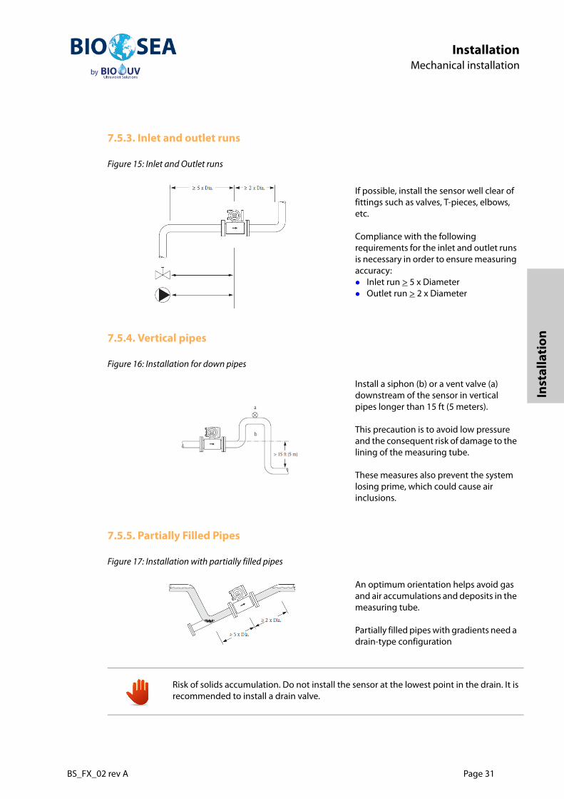
Figure 15: Inlet and Outlet runs
7.5.4. Vertical pipes
Figure 16: Installation for down pipes
7.5.5. Partially Filled Pipes
Figure 17: Installation with partially filled pipes
If possible, install the sensor well clear of fittings such as valves, T-pieces, elbows, etc.
Compliance with the following requirements for the inlet and outlet runs is necessary in order to ensure measuring accuracy:Inlet run > 5 x DiameterOutlet run > 2 x Diameter
Install a siphon (b) or a vent valve (a) downstream of the sensor in vertical pipes longer than 15 ft (5 meters).
This precaution is to avoid low pressure and the consequent risk of damage to the lining of the measuring tube.
These measures also prevent the system losing prime, which could cause air inclusions.
An optimum orientation helps avoid gas and air accumulations and deposits in the measuring tube.
Partially filled pipes with gradients need a drain-type configuration
Risk of solids accumulation. Do not install the sensor at the lowest point in the drain. It is recommended to install a drain valve.

Page 32 BS_FX_02 rev A
InstallationMechanical installation
7.5.6. Vertical orientation
Figure 18: Installation for vertical orientation
7.5.7. Horizontal orientation
Figure 19: Installation for horizontal orientation
This orientation is ideal for self-emptying piping systems.
1- EPD electrode (Empty Pipe Detection)
2- Measuring electrodes (signal detection)
3- Reference electrode (potential equalization)
The measuring electrode-plane should be horizontal. This prevents brief insulation of the two electrodes by entrained air bubbles.
Empty Pipe Detection operates correctly only when the measuring device is installed horizontally and the transmitter housing faces upward. Otherwise there is no guarantee that Empty Pipe Detection will respond if the measuring tube is only partially filled or empty.

BS_FX_02 rev A Page 33
InstallationMechanical installation
Inst
alla
tion
7.6. Installation of sampling ports
If sampling points are not already mounted on the skid, it has to be installed according to the Guidelines forBallast Water Sampling (G2) (resolution MEPC.173(58)), in order to facilitate the verification by Port StateControl of compliance with the discharge standard;
The sample facility should be placed at a point where the flow in the main pipe is fully mixed and fully developed, with the minimum of turbulence.
Samples ports should be located on the discharge line, as near to the point of discharge as practicable.
The sampling port should be oriented such that the opening is facing upstream and its lead length is parallel to the direction of flow and concentric to the discharge pipe.
Figure 20: Sampling pipe orientation
Direction of water flow is shown by red arrows
The sampling pipe is designed to be closable at the opening, removed between sampling intervals or be easily cleaned prior to sampling.
As sampling port is not provided with the system, it has to be designed according to dimensions given in the "Specifications and integration guidelines" book.
Any corrosion of the sampling system will affect sample flow rates and potentially sample representativeness.
As flow control is required for sampling, it is recommended to use diaphragm valves or similar valve types in order to minimize sharp velocity transitions. Ball, gate and butterfly valve types should be avoided as they may cause significant shear forces which may result in organism mortality.

Page 34 BS_FX_02 rev A
InstallationElectrical installation
8. Electrical installation
8.1. General Description
8.1.1. Electrical Main Wiring
The following figures shows general electric configuration of the system.
Figure 21: Synoptic, Example for BIO-SEA® 1000
Installation must be done by approved personal.
De-energized the system before proceeding to works.
BS_FX_02 rev A Page 35
InstallationElectrical installation
Inst
alla
tion
The diagrams for the BIO-SEA® system that has to be installed are in Annex (technical binder).
All BIO-SEA® system need to be connected to ship’s power supply and control board. See 8.2. Main Wiringfrom/to Vessel, page 39
Additionally to these 2 electrical connections, the following wirings may need to be done:
wiring of lamp cable between each cabinet and the corresponding reactor(s): see 8.3. Lamp cable wiring, page 42
wiring between each power cabinet 8.4. Wiring of Profibus cable between cabinets, page 44
wiring between control cabinet and system elements. See 8.5.2. Wiring of pneumatic valves for operations, page 49
8.1.2. Cabinets Location
Power Cabinet
The power cabinet has to be located at maximum 35 m from the UV reactors, in order to respect themaximum length of the powering cable for the UV lamp.
Control Cabinet
The control cabinet has to be at maximum 10 m from the farthest reactor(s), in order to respect themaximum length of the electrical cables for UV and Temperature sensors.
For wiring instructions, see 8. Electrical installation, page 34
Place the cabinets in the numerical order and connect the UV lamps in the same order.
Consider the distance needed for door opening, as well as for man passage with cabinet door open, in accordance with the Class Society’s Rules.
Consider the weight of the cabinets in the implantation of the BWTS.

Page 36 BS_FX_02 rev A
InstallationElectrical installation
8.1.3. Identification of the cabinets
Please refer to wiring diagrams in Annex for cables designation and Ins / Outs.
Table 7: Cabinets number according to BIO-SEA® system size
SystemControl cabinet.
22kW cabinet.with
controller
2x22kW cabinet with
controller2x22kW cabinet
BIO-SEA®100 A0: A1 - -
BIO-SEA®200 A0 - A1 -
BIO-SEA®300 A0 A1 - A2
BIO-SEA®400 A0 - A1 A2
BIO-SEA®500 A0 A1 - A2+A3:
BIO-SEA®600 A0 - A1 A2+A3
BIO-SEA®700 A0 A1 - A2+A3+A4:
BIO-SEA®800 A0 - A1 A2+A3+A4
BIO-SEA®900 A0 A1 - A2+A3+A4+A5
BIO-SEA®1000 A0 - A1 A2+A3+A4+A5
BIO-SEA®1100 A0 A1 - A2+A3+A4+A5+A6
BIO-SEA®1200 A0 - A1 A2+A3+A4+A5+A6
BIO-SEA®1300 A0 A1 - A2+A3+A4+A5+A6+A7
BIO-SEA®1400 A0 - A1 A2+A3+A4+A5+A6+A7
BIO-SEA®1500 A0 A1 - A2+A3+A4+A5+A6+A7+A8
BIO-SEA®1600 A0 - A1 A2+A3+A4+A5+A6+A7+A8
BIO-SEA®1700 A0 A1 - A2+A3+A4+A5+A6+A7+A8+A9
BIO-SEA®1800 A0 - A1 A2+A3+A4+A5+A6+A7+A8+A9
BIO-SEA®1900 A0 A1 - A2+A3+A4+A5+A6+A7+A8+A9+A10
BIO-SEA®2000 A0 - A1 A2+A3+A4+A5+A6+A7+A8+A9+A10
BS_FX_02 rev A Page 37
InstallationElectrical installation
Inst
alla
tion
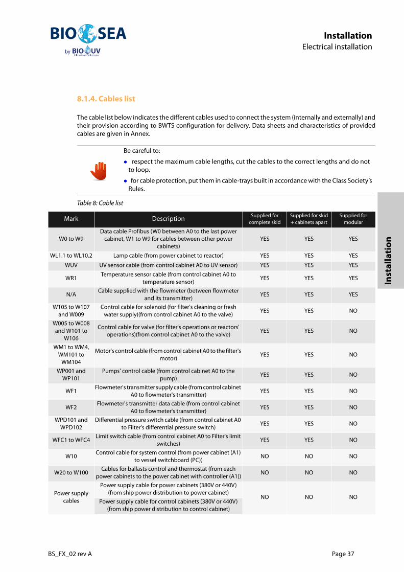
8.1.4. Cables list
The cable list below indicates the different cables used to connect the system (internally and externally) andtheir provision according to BWTS configuration for delivery. Data sheets and characteristics of providedcables are given in Annex.
Be careful to:
respect the maximum cable lengths, cut the cables to the correct lengths and do not to loop.
for cable protection, put them in cable-trays built in accordance with the Class Society’s Rules.
Table 8: Cable list
Mark Description Supplied for complete skid
Supplied for skid + cabinets apart
Supplied for modular
W0 to W9Data cable Profibus (W0 between A0 to the last power
cabinet, W1 to W9 for cables between other power cabinets)
YES YES YES
WL1.1 to WL10.2 Lamp cable (from power cabinet to reactor) YES YES YES
WUV UV sensor cable (from control cabinet A0 to UV sensor) YES YES YES
WR1Temperature sensor cable (from control cabinet A0 to
temperature sensor)YES YES YES
N/ACable supplied with the flowmeter (between flowmeter
and its transmitter)YES YES YES
W105 to W107 and W009
Control cable for solenoid (for filter's cleaning or fresh water supply)(from control cabinet A0 to the valve)
YES YES NO
W005 to W008 and W101 to
W106
Control cable for valve (for filter's operations or reactors' operations)(from control cabinet A0 to the valve)
YES YES NO
WM1 to WM4, WM101 to
WM104
Motor's control cable (from control cabinet A0 to the filter's motor)
YES YES NO
WP001 and WP101
Pumps' control cable (from control cabinet A0 to the pump)
YES YES NO
WF1Flowmeter's transmitter supply cable (from control cabinet
A0 to flowmeter's transmitter)YES YES NO
WF2Flowmeter's transmitter data cable (from control cabinet
A0 to flowmeter's transmitter)YES YES NO
WPD101 and WPD102
Differential pressure switch cable (from control cabinet A0 to Filter's differential pressure switch)
YES YES NO
WFC1 to WFC4Limit switch cable (from control cabinet A0 to Filter's limit
switches)YES YES NO
W10Control cable for system control (from power cabinet (A1)
to vessel switchboard (PC))NO NO NO
W20 to W100Cables for ballasts control and thermostat (from each
power cabinets to the power cabinet with controller (A1))NO NO NO
Power supply cables
Power supply cable for power cabinets (380V or 440V) (from ship power distribution to power cabinet)
NO NO NOPower supply cable for control cabinets (380V or 440V)
(from ship power distribution to control cabinet)
Page 38 BS_FX_02 rev A
InstallationElectrical installation
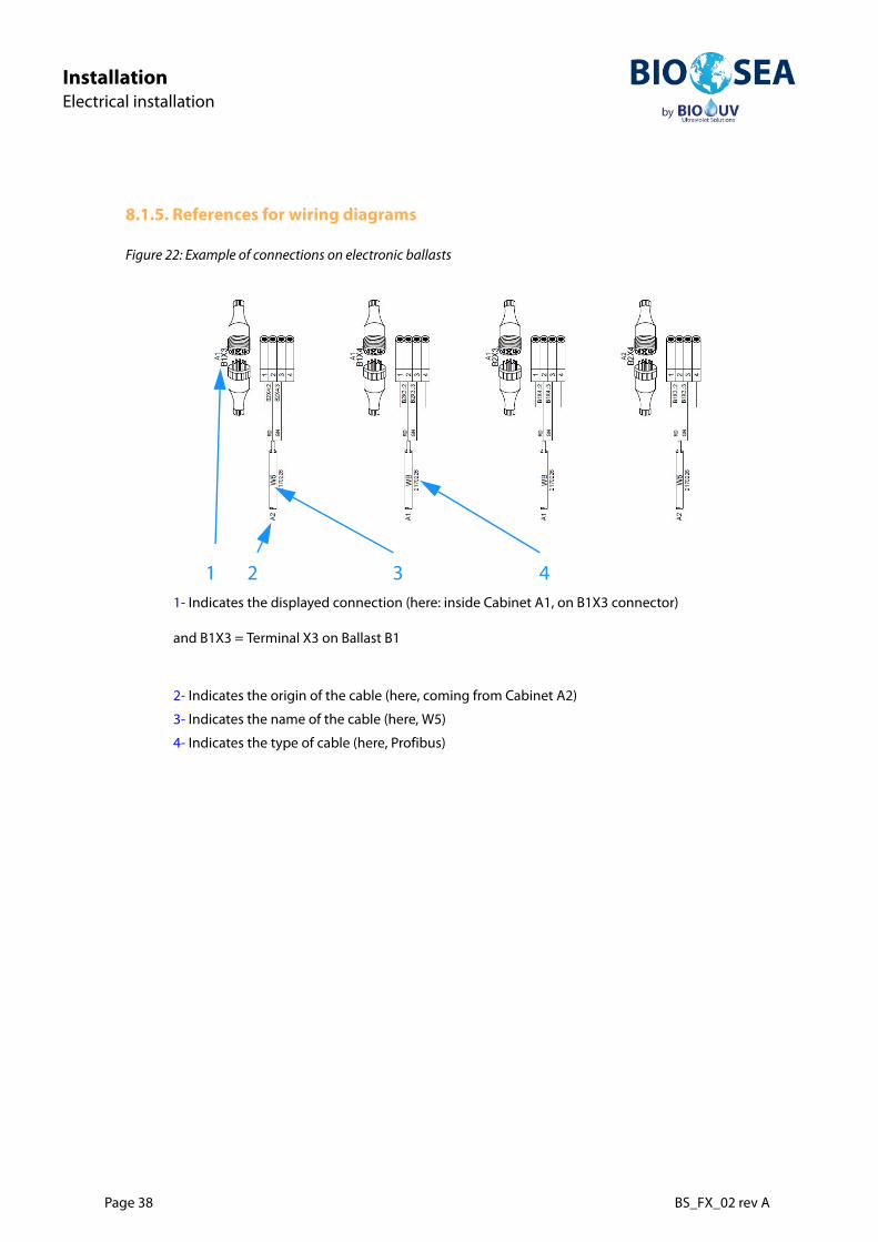
8.1.5. References for wiring diagrams
Figure 22: Example of connections on electronic ballasts
1- Indicates the displayed connection (here: inside Cabinet A1, on B1X3 connector)
and B1X3 = Terminal X3 on Ballast B1
2- Indicates the origin of the cable (here, coming from Cabinet A2)
3- Indicates the name of the cable (here, W5)
4- Indicates the type of cable (here, Profibus)
4321

BS_FX_02 rev A Page 39
InstallationElectrical installation
Inst
alla
tion
8.2. Main Wiring from/to Vessel
8.2.1. Power supply (all cabinets)
Figure 23: Terminal X1 in power cabinet
Figure 24: Wiring of main power supply in cabinet A1
It is recommended to place a distribution cabinet (not provided by BIO-UV) to supply all cabinets. Each cabinet should be protected with a breaker of an amperage higher than the main breaker’s of the corresponding cabinet.
X1 = connection to Power supply (3-ph)X2 = connection to vessel PC control (only in cabinet A1)
1- Grounding terminal
2- Power supply, Phase 1 terminal (L1)
3- Power supply, Phase 2 terminal (L2)
4- Power supply, Phase 3 terminal (L3)
X1 X2
1 2 3 4
Page 40 BS_FX_02 rev A
InstallationElectrical installation
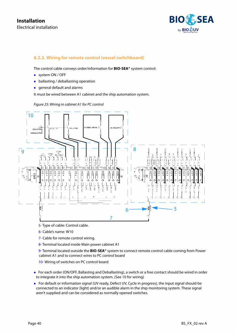
8.2.2. Wiring for remote control (vessel switchboard)
The control cable conveys order/information for BIO-SEA® system control:
system ON / OFF
ballasting / deballasting operation
general default and alarms
It must be wired between A1 cabinet and the ship automation system.
Figure 25: Wiring in cabinet A1 for PC control
For each order (ON/OFF, Ballasting and Deballasting), a switch or a free contact should be wired in order to integrate it into the ship automation system. (See 10 for wiring)
For default or information signal (UV ready, Defect UV, Cycle in progress), the input signal should be connected to an indicator (light) and/or an audible alarm in the ship monitoring system. These signal aren’t supplied and can be considered as normally opened switches.
5- Type of cable: Control cable.
6- Cable’s name: W10
7- Cable for remote control wiring.
8- Terminal located inside Main power cabinet A1
9- Terminal located outside the BIO-SEA® system to connect remote control cable coming from Power cabinet A1 and to connect wires to PC control board
10- Wiring of switches on PC control board
8
7
6 5
9
10

BS_FX_02 rev A Page 41
InstallationElectrical installation
Inst
alla
tion
8.2.3. Wiring 24Vdc power supply
The cables supply 24Vdc to the electronic ballasts and thermostat on each cabinet.
They come from each cabinet (A2, A3, A4, etc) to A1 cabinet.
They are directly connected on terminals between A1 terminals and other cabinet terminals.
Figure 26: Wiring thermostat and ELC power supply
Another touch screen can be ordered and installed on board to provide remote control on the BIO-SEA® BWTS. For this, forecast a space of 195mm x 142mm with a depth of about 70mm at least. Installation instructions will be given on a separate sheet placed in Annex.
This second screen has to be connected to the BIO-SEA® system through Ethernet cable which must not be longer than 90m.
In cabinet n:Xn1 = connection for cabinet thermostatXn2 = connection for 24V supply
Xn1 and Xn2 are wired to cable Wn0
Xn1
Xn2

Page 42 BS_FX_02 rev A
InstallationElectrical installation
8.3. Lamp cable wiring
The lamp cable has to be connected to the electronic ballast (through a terminal inside the power cabinet)and to the UV reactor (through the connection box).
8.3.1. Connection of lamp cable on reactor side
Figure 27: Cable connection on UV reactor
Strip the cable end. Uncover part of the metallic shielding by removing the sheath
Take care to put the cable shielding (a) on the metal strips (b) in the cable gland.Screw the cable gland up tightly
Insert cable into the reactor connexion boxConnect the wire 1 and 2 on terminals
Before wiring the lamp cable inside the power cabinet, make sure the lamp number relates with the suitable power cabinet, see Table 9: Connection between reactor and power cabinet, page 43.
(measurements in mm)
12 80
7.5
12
a b

BS_FX_02 rev A Page 43
InstallationElectrical installation
Inst
alla
tion
8.3.2. Connection of lamp cable on power cabinet side
Figure 28: Cable connection inside power cabinet
Table 9: Connection between reactor and power cabinet
UV nr Cable mark Terminal mark Cabinet nrUV1.1 WL1.1 XL1 A1
UV1.2 WL1.2 XL2 A1
UV2.1 WL2.1 XL1 A2
UV2.2 WL2.2 XL2 A2
UV3.1 WL3.1 XL1 A3
UV3.2 WL3.2 XL2 A3
UV4.1 WL4.1 XL1 A4
UV4.2 WL4.2 XL2 A4
UV5.1 WL5.1 XL1 A5
UV5.2 WL5.2 XL2 A5
UV6.1 WL6.1 XL1 A6
UV6.2 WL6.2 XL2 A6
UV7.1 WL7.1 XL1 A7
UV7.2 WL7.2 XL2 A7
UV8.1 WL8.1 XL1 A8
UV8.2 WL8.2 XL2 A8
UV9.1 WL9.1 XL1 A9
UV9.2 WL9.2 XL2 A9
UV10.1 WL10.1 XL1 A10
UV10.2 WL10.2 XL2 A10
Strip the cable end. Uncover part of the metallic shielding by removing the sheath.Twist the metallic shielding on all the remaining
Mount round lugs on cable’s end Mount rubber sleeve on metallic shielding to insulate itWire round lugs on terminal XL1 for cable WLX (e.g. WL1) and on terminal XL2 for cable WLX+1 (e.g. WL2)Wire metallic shielding on green terminal (1)Place the transparent plastic cover (2)
XL2
2
1
Ballast cables
For lamp cables
XL1

Page 44 BS_FX_02 rev A
InstallationElectrical installation
8.4. Wiring of Profibus cable between cabinets
The 1st bus connection is from Control cabinet (A0) and the X3 terminals on last electronic ballast in the lastpower cabinet (An).
Then there are several serial bus connections between ballasts depending on models from X4 terminals onone cabinet (An) to X3 terminals in the previous cabinet (An-1) till reaching the first ballast located in thepower cabinet with controller (A1).
See example in The following figures shows general electric configuration of the system., page 34.
Refer to main wiring diagram and to electrical drawings for each cabinet.
The bus cables are connected by means of an insulation piercing technique (Fast Connect connection system). The insulation piercing system are designed for 10 connecting cycles.
If you wish to reconnect a line that has already been connected, you must crop it first.
BS_FX_02 rev A Page 45
InstallationElectrical installation
Inst
alla
tion
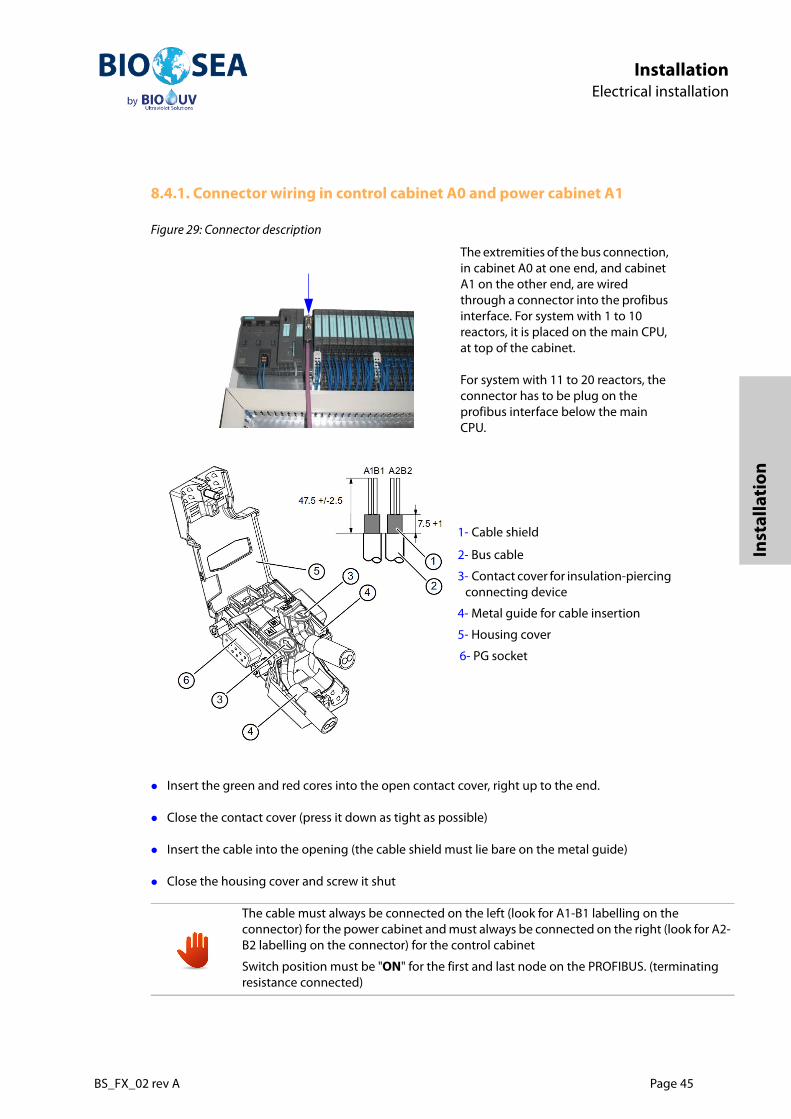
8.4.1. Connector wiring in control cabinet A0 and power cabinet A1
Figure 29: Connector description
Insert the green and red cores into the open contact cover, right up to the end.
Close the contact cover (press it down as tight as possible)
Insert the cable into the opening (the cable shield must lie bare on the metal guide)
Close the housing cover and screw it shut
The extremities of the bus connection, in cabinet A0 at one end, and cabinet A1 on the other end, are wired through a connector into the profibus interface. For system with 1 to 10 reactors, it is placed on the main CPU, at top of the cabinet.
For system with 11 to 20 reactors, the connector has to be plug on the profibus interface below the main CPU.
1- Cable shield
2- Bus cable
3- Contact cover for insulation-piercing connecting device
4- Metal guide for cable insertion
5- Housing cover
6- PG socket
The cable must always be connected on the left (look for A1-B1 labelling on the connector) for the power cabinet and must always be connected on the right (look for A2-B2 labelling on the connector) for the control cabinet
Switch position must be "ON" for the first and last node on the PROFIBUS. (terminating resistance connected)

Page 46 BS_FX_02 rev A
InstallationElectrical installation
8.4.2. Profibus wiring between power cabinets
Figure 30: Connector on electronic ballast (bottom)
1- Picture of the male connector on the electronic ballast, with 4 terminals X1 to X4.
2- Picture of a female connector (x2)
one is plugged on X3 terminalone is plugged on X4 terminal
3- Pin assignment on female connector:
Pin 1: Empty.Pin 2: Red wire of the Profibus cable.Pin 3: Green wire of the Profibus cable.Pin 4: Shielding of the Profibus cable.
4- X1 and X2 terminals are already wired.
5- The control and bus cables are connected to X3 and X4 terminals on the bottom of electronic ballast, in each cabinet.
6- a clamp should be installed around the wires to prevent excessive movements that could lead to disconnect the connector.
Table 10: Overview of Pin assignment
X1.1 X1.2 X1.3 X3.1 X3.2 X3.3 X3.4
INIT PIN INIT GND SAFETY REL BUS VCC BUS B BUS A BUS GND
SAFETY PROFIBUS
SAFETY CONT1
SAFETY CONT2
SAFETY GND
BUS VCC BUS B BUS A BUS GND
X2.1 X2.2 X2.3 X4.1 X4.2 X4.3 X4.4
1
32
54
6

BS_FX_02 rev A Page 47
InstallationElectrical installation
Inst
alla
tion
8.5. Wiring of Control Cabinet
The Control cabinet has to be wired to the system components, such as sensors, filter motor, valves andpumps.
Figure 31: Synoptic
For cable description: see 8.1.4. Cables list, page 37
Each valves, pumps, motor, sensors, differential pressure switch and flow meter are connected on theterminal block of the control cabinet.
.
Depending on devices, cables are colored or numbered and shielded.
They also have different sections depending on power consumption.

Page 48 BS_FX_02 rev A
InstallationElectrical installation
Figure 32: Example of connexion in control cabinet
Refer to wiring diagrams in Annex for more details.
8.5.1. Sensors wiring (UV, temperature and flowmeter)
Cables for temperature and UV sensors should be long enough to be able to place the sensors on thefurtherest UV reactor, even if it they should be placed on the highest reactor.
For flowmeter wiring, please refer to flowmeter manual in Annex.
1- Type of cable: Control cable.
2- Cable’s name: W1033- Cable coming from Y103 valve.
4- Cable going on X3 Terminal located in Cabinet A0.
1234

BS_FX_02 rev A Page 49
InstallationElectrical installation
Inst
alla
tion
8.5.2. Wiring of pneumatic valves for operations
Valves for operations are Y005, Y006,Y007,Y008,Y101, Y102, Y103, Y104
Figure 33: Pneumatic valves wiring
The connector of the pneumatic valves for operations must be wired as indicated on the figure here above
8.5.3. Pumps and motors wiring
Refer to wiring diagram in Annex.

Page 50 BS_FX_02 rev A
InstallationChecking of the BWTS installation
9. Checking of the BWTS installation
9.1. Mechanical Checking
9.1.1. General checking
1- Check presence and state of all Equipment (breakage, coating damage…)
2- Check that the specific BWTS tools are available and complete
3- Check piping is galvanized or painted inside
4- Check pipes are clean inside. It is important to avoid dirt and iron deposit inside piping, otherwise system’s components could be damaged.
5- According to the assembly instruction and the PID of the installation, check the routing of the pipe and the position of:
Each pumps and valves The filter The UV reactors The flow meter
Specific BWTS tools should be available, complete, in good state and calibrated (when necessary)

BS_FX_02 rev A Page 51
InstallationChecking of the BWTS installation
Inst
alla
tion
Figure 34: Example of PID for BIO-SEA®2000
6- Check the conformity of the assembly, circuit piping, clamps. All mountings must be done in accordance with the state of the art.
7- Check that everything is properly tightened and no screw is missing.
8- Check that all the reactors are perpendicular to the manifolds with a square angle at 90° with a triangle.
9- Check that the pressure gauge and the automatic air release valve are on the manifolds and at the right place.
10- Check that the regulator and dehumidifier of air supply is located before the BWTS circuit.
11- Check the air/oil supply is correctly connected to the valves. All connections have to be done in copper.
12- Check that the fresh water regulator and counter is located before the BWTS circuit.
13- Check that the fresh water supply is correctly connected on the filter and on the manifolds of the reactors.
14- Check that the sampling point has been mounted following our recommendations, see7.6. Installation of sampling ports, page 33.
15- Check that the flow meter is in a right way of the flow, at the right position (with the good measurement, of pipe before and after the flow meter, in the right position and properly tightened. See 7.5. Flow meter Installation, page 30).
9.1.2. Filter checking
16- Check the overboard manual valve of the ship for the backwash is open
17- Follow the PID of the installation or the table hereafter to check the name and the rest position of each

Page 52 BS_FX_02 rev A
InstallationChecking of the BWTS installation
valve on the circuit.
18- Check maintenance area is at least equal to manufacturer’s specifications (see filter’s documentation in Annex).
19- Check their opening and their closing in manual. For that, use the manual command on the actuator (air/oil supply must be open, otherwise, the valve won’t change state). The valves should fully open counterclockwise.
20- Check the manual valves of the differential pressure gauge are open.
21- Check the pump is properly tightened and identified (brass name plate).
9.1.3. UV assembly checking
22- Check that the manual valves of the reactors are tightened and can open and close.
23- Check that the clamps on each side of the reactors and the clamp of each UV sensor support are tightened.
24- Follow the PID of the installation or the table hereafter to check the name and the rest position of each valve on the circuit.
Table 11: Identification of Valves and Pumps for filter module
Valve nr Rest pos. DescriptionPump or motor nr
Description
Y101 NC Filter inlet valve / entry valve P101 Filter backwash pump
Y102 NC Filter outlet valve / exit valve M101 Filter backwash motor
Y103 NO Filter by-pass valve
Y104 NC Backwash pump outlet valve
Y105 NC Filter Fresh water filling valve
Y106 NC Sea water drain valve
Y107 NC Filter vent valve
NC = Normally closed valve / NO = Normally open valve / - = Not applicable (e.g. Manual valve)
Table 12: Identification of Valves and Pumps for UV assembly
Valve nr Rest pos. Description Pump nr Description
Y005 NC UV inlet valve P001 UV draining pump
Y006 NC UV outlet valve
Y007 NO UV by-pass valve
Y008 NC UV Draining pump outlet valve
Y009 NC UV Fresh water filling valve
NC = Normally closed valve / NO = Normally open valve / - = Not applicable (e.g. Manual valve)

BS_FX_02 rev A Page 53
InstallationChecking of the BWTS installation
Inst
alla
tion
25- Check that the maintenance area for the reactors and the filter has been respected; see 7. Mechanical installation, page 20. A space of 300mm on one side and 2000mm on the other side of the reactor must remain free to allow quartz sleeve dismounting and lamp changing.
26- Check their opening and their closing in manual. For that, use the manual command on the actuator (air/oil supply must be open, otherwise, the valve won’t change state). The valves should fully open counterclockwise.
27- Leave all the reactors’ manual valves open without filling the reactors with water.
28- Check the pump is properly tightened and identified (brass name plate).

Page 54 BS_FX_02 rev A
InstallationChecking of the BWTS installation
9.2. Electrical checking
29- Check if power supply is correctly designed to supply the system
30- All the electrical circuit assemblies on the ship have to be checked: see 8. Electrical installation, page 34.
31- Check that the cabinets are in the numerical order and that the UV lamps are connected in the same order. seeTable 9: Connection between reactor and power cabinet, page 43.
32- Check that the cabinets are fixed at their correct location and installed in accordance with the rules of the class society of the ship.
33- Check that the electrical cables are :
used for the adequate installation, linked to right device or component, with good quality, correct length, that there are not looped, and that the cable ways are in accordance with the regulation of the class society of the ship, (see 8. Electrical installation, page 34.)
34- Check the electrical connections and the tightened of:
the pumps, the actuator of the valves,the lamps,the motor and detectors of the filter,the distribution cabinet (when installed),the control cabinet,the power cabinets,the electronic ballasts,the UV and temperature sensors.
35- Check that the UV sensor and temperature sensor are on the highest reactor, and that the caps are on the others UV sensor supports.
36- Check in the quartz sleeve of the reactors that the UV lamp are well in their support, the both side of the quartz sleeve by dismounting the cover on the side of the reactors. The lamp has to be in the center of the quartz sleeve.
37- Check the UV lamp and the electronic ballasts connections in the electric box on the reactors.
38- Check addresses of the electronic ballasts, and if necessary, address the electronic ballasts.
For all the connections checking, power supply must be off.
Table 13: Electronic Ballasts Address
Ballast Address Low High Ballast Address Low High
Ballast 1 5 0 Ballast 11 5 1
Ballast 2 6 0 Ballast 12 6 1
Ballast 3 7 0 Ballast 13 7 1
Ballast 4 8 0 Ballast 14 8 1

BS_FX_02 rev A Page 55
InstallationChecking of the BWTS installation
Inst
alla
tion
Figure 35: Profibus address low and high
39- Check thermostats in the power cabinets are set to 60°C
Figure 36: Power cabinet Breakers
Ballast 5 9 0 Ballast 15 9 1
Ballast 6 0 1 Ballast 16 1 2
Ballast 7 1 1 Ballast 17 2 2
Ballast 8 2 1 Ballast 18 3 2
Ballast 9 3 1 Ballast 19 4 2
Ballast 10 4 1 Ballast 20 5 2
1- Thermostat
Table 13: Electronic Ballasts Address
Ballast Address Low High Ballast Address Low High
1

Page 56 BS_FX_02 rev A
InstallationInstructions for piping verification
10. Instructions for piping verification
Verify that there is no leakage on the new piping through a pressure test with water, with the BWTS isolated thanks to the general by-pass.
Flush the ballasts line, with the BWTS by-passed, during 10 min in order to clean the pipes after the installation works at the ship yard.
Open all valves and let the flow flush the line during 10 additional minutes.
These operations MUST be done in coordination with the person in charge of the operations on the ship.

BS_FX_02 rev A Page 57
CommissioningGeneral Recommendations for Commissioning
Com
mis
sion
ing
Commissioning
11. General Recommendations for Commissioning
11.1. Documentation
Before starting Commissioning operations, it is recommended to read Bio-Sea® BWTS general descriptionin Specification book BS_FX_01 , to check the general outcomes noted on the checklist and to keep at hand:
Bio-Sea® PID for your system
General arrangement of BWTS and piping
Bio-Sea® PLC Manual
Tanks and ballast line should be flushed after installation to avoid damaging the system during commissioning.
Page 58 BS_FX_02 rev A
CommissioningGeneral Recommendations for Commissioning
11.2. Required tools
Different tools are needed to undertake the commissioning procedure:
Standard tools (that should be available on board): Screw driver for electrical terminals connections, Torx Wrench, Allen Wrench and Spanner
Specific tools (provided or brought by BIO-UV or its representative)
Sizes vary following the type of equipment
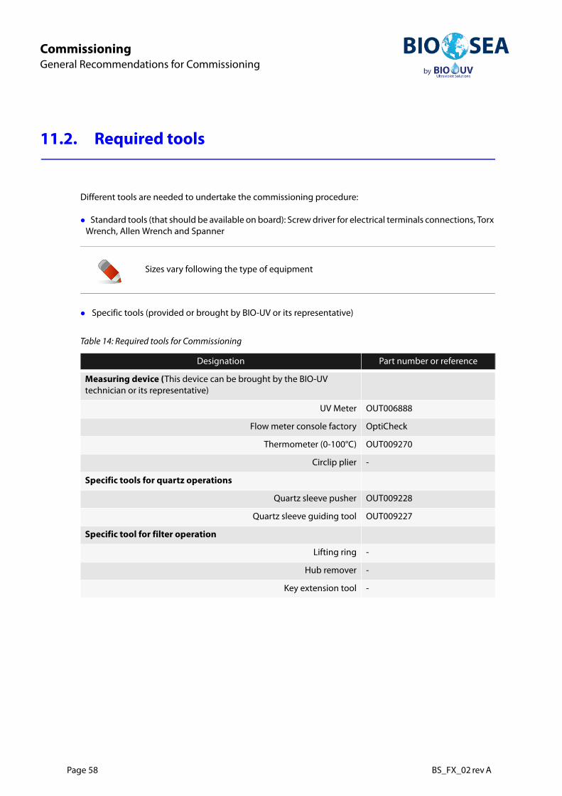
Table 14: Required tools for Commissioning
Designation Part number or reference
Measuring device (This device can be brought by the BIO-UV technician or its representative)
UV Meter OUT006888
Flow meter console factory OptiCheck
Thermometer (0-100°C) OUT009270
Circlip plier -
Specific tools for quartz operations
Quartz sleeve pusher OUT009228
Quartz sleeve guiding tool OUT009227
Specific tool for filter operation
Lifting ring -
Hub remover -
Key extension tool -
BS_FX_02 rev A Page 59
CommissioningPower, Water and Air supply
Com
mis
sion
ing
12. Power, Water and Air supply
12.1. Air / Oil supply for valves
12.1.1. Air supply (pneumatic valves)
Open the main valves of air supply
Check the pressure on the gauge (6 bars).
Check there is no leak on the connections.
12.1.2. Oil supply (hydraulic valves)
Open the main valves of oil supply
Check that the oil supply connection on the valves are not leaking.
12.2. Fresh Water Supply
Open the main valve of fresh water supply.
Check there is no leak on the valves of fresh water supply, on the filter

Page 60 BS_FX_02 rev A
CommissioningPower, Water and Air supply
12.3. Power supply
12.3.1. General power supply
Switch on the ships breaker with the chief engineer
Switch on the main breaker in the distribution cabinet (when installed)
12.3.2. Power cabinets
Proceed as follow for all power cabinets
Check there are no breakers off inside the cabinet
Check the white indicator 380-400v (1) are ON.
Figure 37: Power cabinet
Switch on the main breakers (2)on power cabinets
Check functioning of the air conditioning (3) in the power cabinets, by opening and closing the door: it should stop when opening and start again after closing.
Check the green status indicator on each ELC is ON.))
1- White indicator for 380-440Vac
2- Main power switch of the power cabinet
3- Air conditioning
1
2
3
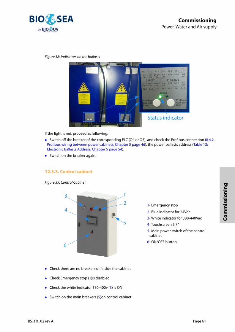
BS_FX_02 rev A Page 61
CommissioningPower, Water and Air supply
Com
mis
sion
ing
Figure 38: Indicators on the ballasts
If the light is red, proceed as following:
Switch off the breaker of the corresponding ELC (Q4 or Q5), and check the Profibus connection (8.4.2. Profibus wiring between power cabinets, Chapter 5 page 46), the power ballasts address (Table 13: Electronic Ballasts Address, Chapter 5 page 54).
Switch on the breaker again.
12.3.3. Control cabinet
Figure 39: Control Cabinet
Check there are no breakers off inside the cabinet
Check Emergency stop (1)is disabled
Check the white indicator 380-400v (3) is ON
Switch on the main breakers (5)on control cabinet
1- Emergency stop
2- Blue indicator for 24Vdc
3- White indicator for 380-440Vac
4- Touchscreen 5.7"
5- Main power switch of the control cabinet
6- ON/OFF button
Status indicator
1
23
6
4
5

Page 62 BS_FX_02 rev A
CommissioningPower, Water and Air supply
Check the blue indicator 24V (2) is ON. The touch screen(4) should be ON (Home Screen) but not active
Press on green button ON (6)(software switch). The white led indicator between the green button ON and the red button OFF is on.
The Touch screen is now activated.
Switch on AUTO mode to be able to begin operations
The system keeps its previous settings before power OFF. So, in case of power failure, there is no need to configure again the PLC.
When the system is electrically powered on, a delay is necessary to get the system ready. So, default messages (General default, Miss general Run/Stop" appear. At this moment, this message is normal and can be acknowledged after a short time, when the communication is effective.
When a UV lamp has turned off, it is necessary to wait about 5 minutes before starting it again. This is a safety not to damage the lamp

BS_FX_02 rev A Page 63
CommissioningTest in MANUAL Mode
Com
mis
sion
ing
13. Test in MANUAL Mode
13.1. Select MANUAL mode
Figure 40: Home screen
Figure 41: Appendix menu
For more details on PLC, please refer to PLC manual BS_FX_04
1- In Home screen menu press Appendix
2- In Appendix menu, Go to Appendix BIO-SEA

Page 64 BS_FX_02 rev A
CommissioningTest in MANUAL Mode
Figure 42: Log on screen
Figure 43: Appendix menu
Figure 44: Mode
3- Enter Login and Password to access to Appendix BIO-SEA
4- In Appendix BIO-SEA menu press Mode
5- Select Manual Mode
6- Press Return to Appendix Bio-sea

BS_FX_02 rev A Page 65
CommissioningTest in MANUAL Mode
Com
mis
sion
ing
13.2. Filter module check
13.2.1. Filter Selection
Figure 45: Select Filter
13.2.2. Check Filter settings
Figure 46: Appendix BIO-UV menu
Figure 47: Filter menu
Go to the Appendix Bio-UV menu (see Figure 41: Appendix menu, page 63)Press Select Filtrex
Go to Filter
Check the settings to compare them with the list of factory settings
Time controls DP = 5 s
Other Parameters = 0 s
Periodic cleaning = 30mn
Press Return

Page 66 BS_FX_02 rev A
CommissioningTest in MANUAL Mode
13.2.3. Check filter valves
Go to Mechanism Filter1
Figure 48: General use of filter Mechanisms in Manual Mode
The «Mechanism Filter 2" screen is active only when two filters are installed in parallel on board.
Valves
1- White actuator = not activated (valve in its normal position, eg. Y101 is Normally Open)
2- Green valve = valve open
3- Yellow valve = valve closed
4- Green actuator = activated (valve Y103 is NO, and has been closed)
Buttons OPEN / CLOSE5- White button = Action authorized (eg.
press button to open valve Y104)
6- Grey button = No permission to change the status
7- Buttons to start/stop Pump P101
8- Button to start/stop the rotation of the filter’s cleaning axis
9- Lights on if filter’s axis cleaning is moving
3 4
6
1
5
2
9 87

BS_FX_02 rev A Page 67
CommissioningTest in MANUAL Mode
Com
mis
sion
ing
Check all the valves one by one, 3 times open and close, to ensure their correct operation.:
13.2.4. Check the backwash pump (P101)
Open valve Y104 (suction valve of the backwash pump P101).
Make a quick «Start / Stop » to check the rotating direction of the pump rotor.
If second filter is mounted in parallel, do the same for the pump P201
13.2.5. Check the motor (M101)
Press the start/stop signal (under M101 on on Figure 48: General use of filter Mechanisms in Manual Mode, page 66) with a delay of rotation.
Repeat this test 3 more times.
Return to Appendix Bio-UV menu.
If second filter is mounted in parallel, do the same for the motor M201
Table 15: Identification of Valves and Pumps for filter module
Valve nr Rest pos. DescriptionPump or motor nr
Description
Y101 NC Filter inlet valve / entry valve P101 Filter backwash pump
Y102 NC Filter outlet valve / exit valve M101 Filter backwash motor
Y103 NO Filter by-pass valve
Y104 NC Backwash pump outlet valve
Y105 NC Filter Fresh water filling valve
Y106 NC Sea water drain valve
Y107 NC Filter vent valve
Y107 NC Filter vent valve
NC = Normally closed valve / NO = Normally open valve / - = Not applicable (e.g. Manual valve)
In case of a filter with multiple motors configuration, other motors (M102, M103 and M104) can be found on another screen. A button will be placed next to M101 to access this screen
In case of two filter in parallel, other valves can be found with numbers starting with "2" instead of "1"
The pump P101 cannot be started (so Start button stays grey) if valve Y104 isn’t open.
If the pump P101 lights red, a defect is present and must be solved, then acknowledged.

Page 68 BS_FX_02 rev A
CommissioningTest in MANUAL Mode
13.3. UV assembly checking
13.3.1. Check UV Settings
Figure 49: Appendix BIO-SEA menu
Figure 50: UV menu
In the Appendix BIO-SEA menu, press UV
In UV screen, press Parameters
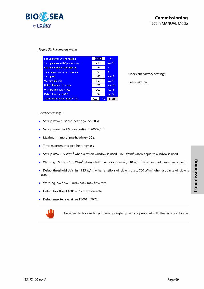
BS_FX_02 rev A Page 69
CommissioningTest in MANUAL Mode
Com
mis
sion
ing
Figure 51: Parameters menu
Factory settings:
Set up Power UV pre-heating= 22000 W.
Set up measure UV pre-heating= 200 W/m².
Maximum time of pre-heating= 60 s.
Time maintenance pre-heating= 0 s.
Set up UV= 185 W/m² when a teflon window is used, 1025 W/m² when a quartz window is used.
Warning UV min= 150 W/m² when a teflon window is used, 830 W/m² when a quartz window is used.
Defect threshold UV min= 125 W/m² when a teflon window is used, 700 W/m² when a quartz window is used.
Warning low flow FT001= 50% max flow rate.
Defect low flow FT001= 5% max flow rate.
Defect max temperature TT001= 70°C..
Check the factory settings
Press Return
The actual factory settings for every single system are provided with the technical binder

Page 70 BS_FX_02 rev A
CommissioningTest in MANUAL Mode
13.3.2. Check UV valves
Figure 52: Mechanism UV
Check all the valves one by one, 3 times open and close, to ensure their correct operation.:
13.3.3. Check the draining pump (P001)
Open valve Y008 (suction valve of the draining pump P001).
Make a quick «Start / Stop» to check the rotating direction of the pump rotor.
In Appendix Bio-sea menu (see Figure 41: Appendix menu, page 63), press Mechanism UV to access this page
Table 16: Identification of Valves and Pumps of UV assembly
Valve nr Rest pos. Description Pump nr Description
Y005 NC UV inlet valve P001 UV draining pump
Y006 NC UV outlet valve
Y007 NO UV by-pass valve
Y008 NC UV Draining pump outlet valve
Y009 NC UV Fresh water filling valve
NC = Normally closed valve / NO = Normally open valve / - = Not applicable (e.g. Manual valve)
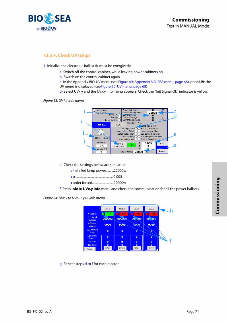
BS_FX_02 rev A Page 71
CommissioningTest in MANUAL Mode
Com
mis
sion
ing
13.3.4. Check UV lamps
1- Initialize the electronic ballast (it must be energized):
a- Switch off the control cabinet, while leaving power cabinets on. b- Switch on the control cabinet againc- In the Appendix BIO-UV menu (see Figure 49: Appendix BIO-SEA menu, page 68), press UV: theUV menu is displayed (seeFigure 50: UV menu, page 68)d- Select UVx.y and the UVx.y info menu appears. Check the "Init Signal Ok" indicator is yellow.
Figure 53: UV1.1 info menu
e- Check the settings below are similar to :
Installed lamp power..........22000w
p.................................................0.005
order forced...........................22000w
f- Press Info in UVx.y info menu and check the communication for all the power ballasts
Figure 54: UVx.y to UVx+1.y+1 info menu
g- Repeat steps d to f for each reactor
d
e
e
e
j
i
j
j
f
h

Page 72 BS_FX_02 rev A
CommissioningTest in MANUAL Mode
2- Check UV lamp functioning:
h- In the UVx.y to UVx+1.y+1 info menu, select the corresponding UV lamp i- In the UVx.y info menu (seeFigure 53: UV1.1 info menu, page 71), switch off the dimming bypressing on "Dimming in progress" button. Indicator next to the button should be NO.j- Press Start button: the UV lamp should light on at ordered forced power (e). As there is no flowin the reactor, stop the lamp as soon as the power is reached or after 1 or 2 minutes. Beforestopping the lamp, write the value in "Measure UV"
k- When lamp is completely off, mount UV sensor on the next reactor and mount the UV meter atits place.
Figure 55: UV Meter
l- Press Start button: the UV lamp should light on at ordered forced power (e). As there is no flowin the reactor, stop the lamp as soon as the power is reached or after 1 or 2 minutes. Beforestopping the lamp, write the value on the UV meter.m- Compare the value of "Measure UV" and the value on "UV meter". They should not differ frommore than 20%. otherwise, sensor should be replaced by a new one (and verified again). n- In the UVx.y info menu (see Figure 53: UV1.1 info menu, page 71), switch on the dimming bypressing on "Dimming in progress" button (i). Indicator next to the button should be YES.o- Repeat steps h to n for each reactor
To be able to check the lamps, it is necessary to have reactors full of fresh water. In other case, BWTS could be damaged.
The use of a UV meter is advised yearly to check the reading of the plant UV sensor.

BS_FX_02 rev A Page 73
CommissioningTest in MANUAL Mode
Com
mis
sion
ing
13.4. Check other factory Setting
13.4.1. Check Measured Parameters
Figure 56: Parameters Measure
13.4.2. Check Mechanical Response
Figure 57: Parameters Mechanism
13.4.3. Check Date and Time
Figure 58: Date and Time
In Appendix Bio-UV menu (see Figure 46: Appendix BIO-UV menu, page 65), press Param. Measure.In the Parameters Measure menu, check the settings (as shown Figure 56: Parameters Measure, page 73) with the list of factory settings.Press Return to Appendix Bio-UV
In Appendix Bio-UV menu (see Figure 46: Appendix BIO-UV menu, page 65), press Param. mecanisms.In the Parameters Mechanism menu, check the settings with the list of factory settings:All valves Yxx1 to Yxx8 = 10s, Y009 = 0sMotors and pumps Mxxx et Pxxx = 0sPress Return to Appendix Bio-UV
In Appendix Bio-UV menu (see Figure 46: Appendix BIO-UV menu, page 65), press Date and Time.Check the Date and the hour.Press Return to Appendix Bio-UV

Page 74 BS_FX_02 rev A
CommissioningSet washing parameters
14. Set washing parameters
14.1. Filter cleaning
14.1.1. Filling of the Filters
Check that the main supply valve for the fresh water is open.
Figure 59: Mechanism Filter 1
To ensure the filter full, check the fresh water counter: it should not give more indication. If the freshwater counter still gives indication, check for a leak
Check that the gauge on the filter is at the same pressure that the fresh water circuit of the ship. If not, check the automatic air release and the fresh water supply.
When all the checks are done, return to the control screen and close the valve Y107 then Y105.
This operation requires using fresh water circuit of the ship. While performing filling and emptying of UV reactors, verification of absence of leaking can be done too.
Open valve of air release Y107.Open valve of filling fresh water Y105.Check the fresh water circulation by the fresh water counter (if installed).Note the time of filling in mn.Check the leak and the air blowing out the automatic air release

BS_FX_02 rev A Page 75
CommissioningSet washing parameters
Com
mis
sion
ing
14.1.2. Emptying The Filter (Manual Mode)
On the menu Mechanism Filter 1 (see )
The valve Y104 is the suction valve of the draining pump P101.
The valve Y104 must be open to allow draining pump P101.
Note the time of emptying the manifolds and the reactors, for the parameters of emptying, in the automatic operation.
Open valve Y104 and start pump P101.
When the filter is empty, the gauge of the filter is on 0 and the draining pump changes of noise because ofthe air.
Close valve Y104 and stop pump P101
Repeat the procedure for filling and leave the filter
14.2. UV cleaning
14.2.1. Filling Reactors and Manifolds (Manual mode)
Check that the main supply valve for the fresh water is open.
Check that all the manual valves of the reactors are open.(2 per reactor)
Check that the safety manual valves for the air release automatic are open.
Figure 60: Mechanism UV
To ensure the reactors and the manifolds full, check the fresh water counter: it should not give more indication. If the freshwater counter still gives indication, check for a leak
Go to the Appendix Bio-UV menu (see Figure 41: Appendix menu, page 63)Press Mechanism UVPress open Y009 valve for filling fresh water.Note the time of filling of the reactors and manifolds in minutes.During the filling operation, check absence of leakage and the air blowing out the automatic air release.
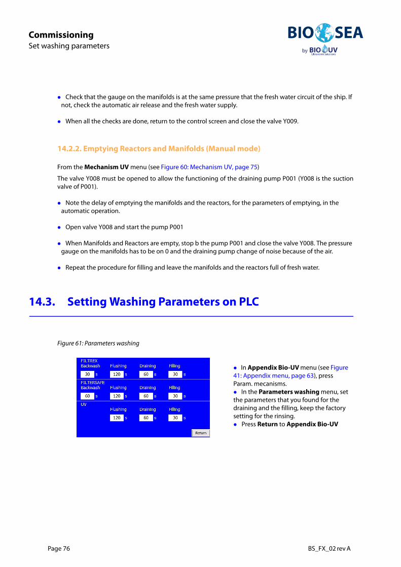
Page 76 BS_FX_02 rev A
CommissioningSet washing parameters
Check that the gauge on the manifolds is at the same pressure that the fresh water circuit of the ship. If not, check the automatic air release and the fresh water supply.
When all the checks are done, return to the control screen and close the valve Y009.
14.2.2. Emptying Reactors and Manifolds (Manual mode)
From the Mechanism UV menu (see Figure 60: Mechanism UV, page 75)
The valve Y008 must be opened to allow the functioning of the draining pump P001 (Y008 is the suctionvalve of P001).
Note the delay of emptying the manifolds and the reactors, for the parameters of emptying, in the automatic operation.
Open valve Y008 and start the pump P001
When Manifolds and Reactors are empty, stop b the pump P001 and close the valve Y008. The pressure gauge on the manifolds has to be on 0 and the draining pump change of noise because of the air.
Repeat the procedure for filling and leave the manifolds and the reactors full of fresh water.
14.3. Setting Washing Parameters on PLC
Figure 61: Parameters washing
In Appendix Bio-UV menu (see Figure 41: Appendix menu, page 63), press Param. mecanisms.In the Parameters washing menu, set the parameters that you found for the draining and the filling, keep the factory setting for the rinsing.Press Return to Appendix Bio-UV

BS_FX_02 rev A Page 77
CommissioningTest In Automatic Mode
Com
mis
sion
ing
15. Test In Automatic Mode
15.1. Test of the flow meter
In coordination with the person in charge of the operations on the vessel:
Check the screen (Process menu) if the values of the flow meter are in concordance with the flow of theballast pump of the ship.
When the flushing of the ballast line has started, check for leaks on all the flanges, the valves, the flow meter.
Check the screen (Process menu) if the values of the flow meter are in concordance with the flow of the ballast pump of the ship.
Warning, do not use the backwash pump without water to not damage the pump.
System should be filled with fresh water before starting tests in AUTO mode
Ballast line should have already been flushed (about 15mn) at the end of the installation steps to clean the dirts from installation in the ship yard.
All described tests are made for local tests. However, if remote control is installed, all these tests has to be performed once again with the remote control.

Page 78 BS_FX_02 rev A
CommissioningTest In Automatic Mode
15.2. Select AUTO mode
Figure 62: Home screen
Figure 63: Auto Mode selected
In case of default, check and acquit the default. For that:
Go to Alarm screen (accessible since the Home screen) and read the present default.
Acquit the default
If the default is still present, solve it and acquit it. Repeat the operation until the alarmlist is blank.
In Home screen menu press AUTO
The AUTO mode is selected

BS_FX_02 rev A Page 79
CommissioningTest In Automatic Mode
Com
mis
sion
ing
15.3. Test of automatic ballasting
15.3.1. Ballast water management for Ballasting process
Figure 64: Example of PID for ballasting process
Before launching Ballasting or Deballasting operations, it is necessary to determine if the ballast pump starts before or after the UV system. For these tests, Ballast pump will start first. However, the other solution is possible.
Take care to switch off deballasting mode before the ballast pump stops as reactors should always stay filled with water.
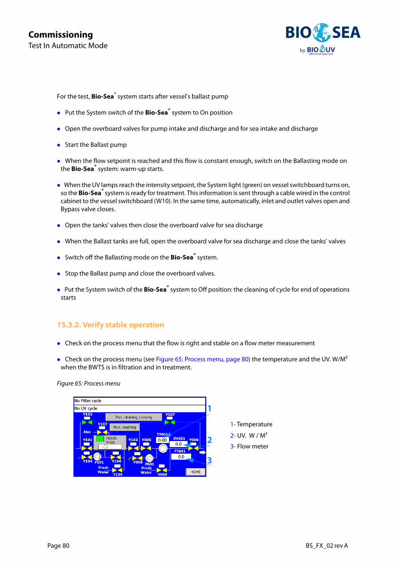
Page 80 BS_FX_02 rev A
CommissioningTest In Automatic Mode
For the test, Bio-Sea® system starts after vessel’s ballast pump
Put the System switch of the Bio-Sea® system to On position
Open the overboard valves for pump intake and discharge and for sea intake and discharge
Start the Ballast pump
When the flow setpoint is reached and this flow is constant enough, switch on the Ballasting mode on the Bio-Sea® system: warm-up starts.
When the UV lamps reach the intensity setpoint, the System light (green) on vessel switchboard turns on, so the Bio-Sea® system is ready for treatment. This information is sent through a cable wired in the control cabinet to the vessel switchboard (W10). In the same time, automatically, inlet and outlet valves open and Bypass valve closes.
Open the tanks’ valves then close the overboard valve for sea discharge
When the Ballast tanks are full, open the overboard valve for sea discharge and close the tanks’ valves
Switch off the Ballasting mode on the Bio-Sea® system.
Stop the Ballast pump and close the overboard valves.
Put the System switch of the Bio-Sea® system to Off position: the cleaning of cycle for end of operations starts
15.3.2. Verify stable operation
Check on the process menu that the flow is right and stable on a flow meter measurement
Check on the process menu (see Figure 65: Process menu, page 80) the temperature and the UV. W/M² when the BWTS is in filtration and in treatment.
Figure 65: Process menu
1- Temperature
2- UV. W / M²
3- Flow meter
1
2
3
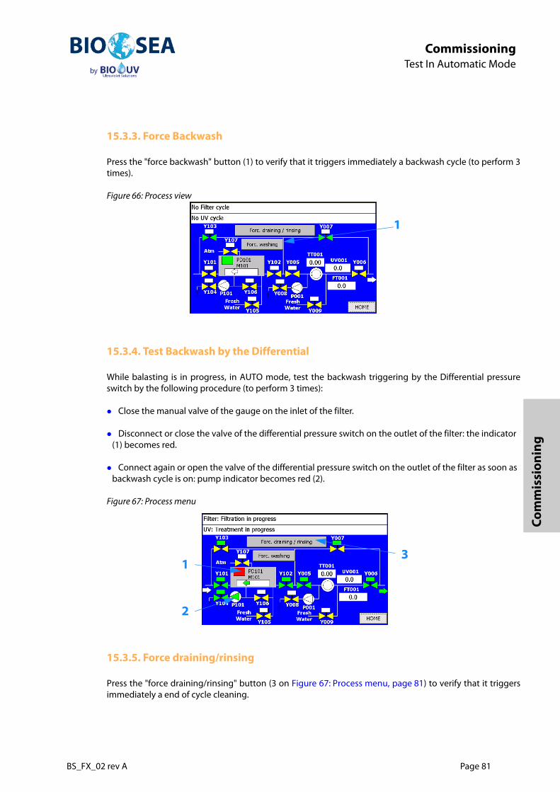
BS_FX_02 rev A Page 81
CommissioningTest In Automatic Mode
Com
mis
sion
ing
15.3.3. Force Backwash
Press the "force backwash" button (1) to verify that it triggers immediately a backwash cycle (to perform 3times).
Figure 66: Process view
15.3.4. Test Backwash by the Differential
While balasting is in progress, in AUTO mode, test the backwash triggering by the Differential pressureswitch by the following procedure (to perform 3 times):
Close the manual valve of the gauge on the inlet of the filter.
Disconnect or close the valve of the differential pressure switch on the outlet of the filter: the indicator (1) becomes red.
Connect again or open the valve of the differential pressure switch on the outlet of the filter as soon as backwash cycle is on: pump indicator becomes red (2).
Figure 67: Process menu
15.3.5. Force draining/rinsing
Press the "force draining/rinsing" button (3 on Figure 67: Process menu, page 81) to verify that it triggersimmediately a end of cycle cleaning.
1
1
2
3

Page 82 BS_FX_02 rev A
CommissioningTest In Automatic Mode
15.4. Test of automatic deballasting
15.4.1. Ballast water management for deballasting process
Figure 68: Example of PID for deballasting process
The test on the Deballasting must be done in coordination with the second-captain and the chief engineer.
Take care to switch off deballasting mode before the pump stops as reactors should always stay filled with water.

BS_FX_02 rev A Page 83
CommissioningTest In Automatic Mode
Com
mis
sion
ing
For the test, Bio-Sea® system starts after vessel’s ballast pump.
Put the System switch of the Bio-Sea® system to On position
Check overboard valves are closed
Open tanks’ valves for pump intake and discharge (no treatment)
Start Ballast pump to create a circulation
When the flow setpoint is reached and this flow is constant enough, switch on the Ballasting mode on the Bio-Sea® system: warm-up starts
When the UV lamps reach the intensity setpoint, the System light (green) on vessel switchboard turns on, so the Bio-Sea® system is ready for treatment. This information is sent through a cable wired in the control cabinet to the vessel switchboard (W10). In the same time, automatically, inlet and outlet valves open and Bypass valve closes.
Open overboard outlet valve (to the sea)
When tanks are almost empty (flow should decrease), close overboard outlet valve (to the sea)
Switch off the Deballasting mode on the Bio-Sea® system.
Stop Ballast pump
Close tanks’ valves
Put the System switch of the Bio-Sea® system to Off position: the cleaning of cycle for end of operations starts
15.4.2. Verify stable operation
Check on the process menu that the flow is right and stable on a flow meter measurement
Check on the process menu (see Figure 69: Process menu, page 83) the temperature and the UV. W/M² when the BWTS is in filtration and in treatment.
Figure 69: Process menu
1- Temperature
2- UV. W / M²
3- Flow meter
1
2
3
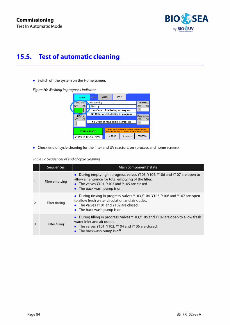
Page 84 BS_FX_02 rev A
CommissioningTest In Automatic Mode
15.5. Test of automatic cleaning
Switch off the system on the Home screen.
Figure 70: Washing in progress» indicator
Check end of cycle cleaning for the filter and UV reactors, on «process and home screen»
Table 17: Sequences of end of cycle cleaning
Sequences Main components’ state
1 Filter emptying
During emptying in progress, valves Y103, Y104, Y106 and Y107 are open to allow air entrance for total emptying of the filter.The valves Y101, Y102 and Y105 are closed.The back wash pump is on
2 Filter rinsing
During rinsing in progress, valves Y103,Y104, Y105, Y106 and Y107 are open to allow fresh water circulation and air outlet.The Valves Y101 and Y102 are closed.The back wash pump is on.
3 Filter filling
During filling in progress, valves Y103,Y105 and Y107 are open to allow fresh water inlet and air outlet.The valves Y101, Y102, Y104 and Y106 are closed.The backwash pump is off.

BS_FX_02 rev A Page 85
CommissioningTest In Automatic Mode
Com
mis
sion
ing
15.5.1. When the end cycle cleaning is finished:
Check end of cycle cleaning for the filter and UV reactors, on «process and home screen»
Check the valves and the pumps, are closed, on the process menu
Ensure the filter and the reactors are full, the gauge on the filter and the reactors has to be at the same pressure that the fresh water circuit of the ship.
4UV reactors emptying
During emptying in progress, valves Y007 and Y008 are open to empty the uv reactors.Automatic inlet air valve allow air entrance to avoid vacuum.The valves y005, y006 and y009 are closed.The draining pump is on.
5 UV reactors rinsing
During emptying in progress, valves Y007, Y008 and Y009 are open to allow fresh water inlet and to rinse the uv reactors.Automatic inlet air valve allow air entrance to avoid vacuum.The valves Y005 and Y006 are closed.The draining pump is on.
6 UV reactors filling
During filling in progress, valves Y007, Y009 and automatic inlet air valve are open to allow fresh water inlet and air outlet.The valves Y005, Y006 and Y008 are closed.The draining pump is off.
Table 17: Sequences of end of cycle cleaning
Sequences Main components’ state
Page 86 BS_FX_02 rev A
CommissioningOperational Checks
16. Operational Checks
16.1. Circulation with BWTS on the line
Before loading operation make a ballasting / deballasting on each tank.
16.2. Stripping operation
When using eductors for stripping operation, the remaining ballast water is mixed with the driving water,that is usually local water containing organisms. To be in compliance with the Ballast Water Convention, thisstripped water should meet the D-2 standard at discharge.
Depending on ship configuration, installer can choose between the following options:
1- Avoid using eductors
a- Remaining ballast water is stripped using a vacuum pump in the normal ballast line and then discharged stripped water through normal deballasting procedure with UV treatment.b- Remaining ballast water is first collected in a specific ballast tank, without mixing withunmanaged water, and then discharge through normal deballasting procedure.
2- All ballast water is treated before mixing with driving water (by recirculation when tank is filled, or by connecting the UV module before the mixing point). In this case, the discharge sampling point has to be located before the mixture of the fully treated ballast water with the unmanaged driving water.
3- The driving water is treated water coming from another ballast tank, and the mixture is discharged through normal deballasting procedure.
4- The driving water is preferably treated at uptake (in order to eliminate local organisms that could contaminate a PSC discharge sample) before mixing it with ballast water, and the mixture is discharged
In coordination with the person in charge of teh operations on the vessel, every ballast has to be «ballasted and deballasted» with the BWTS to ensure that the loading operation can be done with the BWTS in all conditions.
In the operation test, a flow measurement table has to be done for all the ballasts with the flow measurement, every 5 minutes from the start to the end of the operation and the number of the ballast for each testing.

BS_FX_02 rev A Page 87
CommissioningOperational Checks
Com
mis
sion
ing
through normal deballasting procedure.
After choosing the stripping solution, perfom a stripping test.
16.3. Check the sampling valves
Ensure that there is a water flow by opening and closing the valves.
16.4. First start of archiving
The following steps has to be carried out when all the installation and commissioning operations are doneand the system is ready for treatment.
Check archiving is in progress the File Screen. If not, press "START RECORDING" button (3)
Figure 71: Archiving functions
Check time and date are correct
When the selected solution uses UV module at the stripped flow rate, the minimum acceptable flow rate in each reactor is 5 m3/h, for maintaining UV lamps cooling during the stripping operation.
1- Display of measured parameters (curves).
2- Archiving function:
Blue= Archiving in progress, White= No archiving
3- To launch archiving on memory card
4- To stop archiving
1
3 4
2

Page 88 BS_FX_02 rev A
CommissioningOperational Checks
Figure 72: Date and Time
Reset all the counters
Figure 73: Info UV1.1 to UV2.2
Figure 74: Info Values screen
1- Touch this text box to enter the date.
2- Touch this text box to enter the day time.
3- Choose the Time zone
4- Press this button to set new date and time on PLC and Touch Screen (5).
2
4
3
1 5

BS_FX_02 rev A Page 89
CommissioningOperational Checks
Com
mis
sion
ing
Check SD card is inserted behind the screen in the memory SD card slot (Data)
Figure 75: SD Card location
Put a lead seal on the safety lock of the SD card slot
Do not remove SD card: there is a risk to damage the files inside the SD card if archiving is in progress.
1- Slot for memory card (SD or MMC format)
2- Slot for system memory card (not used)
3- Safety lock