Embed Size (px)
Citation preview
21
BVMA-3A-0409
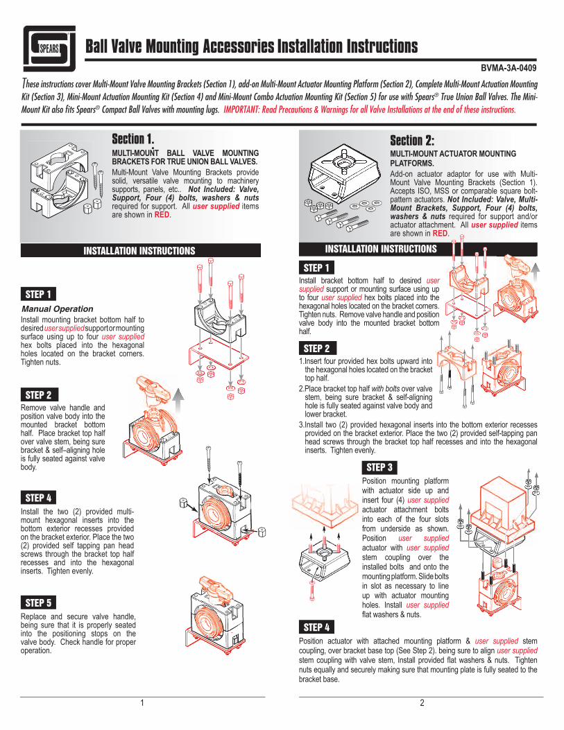
Section 1:MULTI-MOUNT BALL VALVE MOUNTING BRACKETS FOR TRUE UNION BALL VALVES.Multi-Mount Valve Mounting Brackets provide solid, versatile valve mounting to machinery supports, panels, etc.. Not Included: Valve, Support, Four (4) bolts, washers & nuts required for support. All user supplied items are shown in RED.
INSTALLATION INSTRUCTIONS
STEP 1
Install mounting bracket bottom half to desired user supplied support or mounting surface using up to four user supplied hex bolts placed into the hexagonal holes located on the bracket corners.Tighten nuts.
STEP 2 Remove valve handle and position valve body into the mounted bracket bottom half. Place bracket top half over valve stem, being sure bracket & self–aligning hole is fully seated against valve body.
STEP 4 Install the two (2) provided multi-mount hexagonal inserts into the bottom exterior recesses provided on the bracket exterior. Place the two (2) provided self tapping pan head screws through the bracket top half recesses and into the hexagonal inserts. Tighten evenly.
STEP 5 Replace and secure valve handle, being sure that it is properly seated into the positioning stops on the valve body. Check handle for proper operation.
Section 2:MULTI-MOUNT ACTUATOR MOUNTING PLATFORMS.Add-on actuator adaptor for use with Multi-Mount Valve Mounting Brackets (Section 1). Accepts ISO, MSS or comparable square bolt-pattern actuators. Not Included: Valve, Multi-Mount Brackets, Support, Four (4) bolts, washers & nuts required for support and/or actuator attachment. All user supplied items are shown in RED.
INSTALLATION INSTRUCTIONS
STEP 1 Install bracket bottom half to desired user supplied support or mounting surface using up to four user supplied hex bolts placed into the hexagonal holes located on the bracket corners. Tighten nuts. Remove valve handle and position valve body into the mounted bracket bottom half.
STEP 2 1.Insert four provided hex bolts upward into
the hexagonal holes located on the bracket top half.
2.Place bracket top half with bolts over valve stem, being sure bracket & self-aligning hole is fully seated against valve body and lower bracket.
3.Install two (2) provided hexagonal inserts into the bottom exterior recesses provided on the bracket exterior. Place the two (2) provided self-tapping pan head screws through the bracket top half recesses and into the hexagonal inserts. Tighten evenly.
STEP 3 Position mounting platform with actuator side up and insert four (4) user supplied actuator attachment bolts into each of the four slots from underside as shown. Position user supplied actuator with user supplied stem coupling over the installed bolts and onto the mounting platform. Slide bolts in slot as necessary to line up with actuator mounting holes. Install user supplied fl at washers & nuts.
STEP 4 Position actuator with attached mounting platform & user supplied stem coupling, over bracket base top (See Step 2). being sure to align user supplied stem coupling with valve stem, Install provided fl at washers & nuts. Tighten nuts equally and securely making sure that mounting plate is fully seated to the bracket base.
Ball Valve Mounting Accessories Installation Instructions
These instructions cover Multi-Mount Valve Mounting Brackets (Section 1), add-on Multi-Mount Actuator Mounting Platform (Section 2), Complete Multi-Mount Actuation Mounting Kit (Section 3), Mini-Mount Actuation Mounting Kit (Section 4) and Mini-Mount Combo Actuation Mounting Kit (Section 5) for use with Spears® True Union Ball Valves. The Mini-Mount Kit also fi ts Spears® Compact Ball Valves with mounting lugs. IMPORTANT: Read Precautions & Warnings for all Valve Installations at the end of these instructions.
Manual Operation

4 3
MINI-MOUNT ACTUATION MOUNTING KITS FOR TRUE UNION AND COMPACT BALL VALVES.Kit includes Bracket Base Hardware and Universal Actuator Mounting Plate. Not Included: Valve, Support, Four (4) bolts, washers & nuts required for support and/or actuator attachment. All user supplied items are shown in RED. Accepts ISO, MSS or comparable square bolt-pattern actuators.
INSTALLATION INSTRUCTIONS
STEP 1 Position bracket base top over valve stem and handle stop. Insure Mini-Mount bracket tabs are fully engaged with valve body Lugs. Insert the two (2) provided short bolts through clamp hole on the inside of bracket, through the valve body clamp hole and through the bracket clamp hole opposite of insertion. Install lock-nuts. Tighten lock-nuts making sure that the bracket base is fully seated on the valve shoulder.
STEP 2 Insert four (4) provided bolts through top of mounting plate into each of the four slots. Note: “Actuator Side” UP as printed on the mounting plate. Next, insert the four (4) user supplied actuator mounting bolts through bottom of mounting plate, inside of installed provided bolts.
STEP 3 Position user supplied actuator over top of mounting plate, align user supplied actuator bolts to actuator and tighten evenly.
STEP 4 Insert stem coupler and p o s i t i o n a s s e m b l e d components over Mini-Mount Actuation Mounting Bracket and align the four (4) installed provided bolts to mate with the provided washers and nuts and tighten evenly.
Section 4:Section 3:COMPLETE MULTI-MOUNT ACTUATION MOUNTING KITS.Multi-Mount Actuator Mounting Platform & Multi-Mount Valve Mounting Bracket in one kit. Provides solid, fully supported valve & actuator mounting. Accepts ISO, MSS or comparable square bolt-pattern actuators. Not Included: Valve, Support, Four (4) bolts, washers & nuts required for support and/or actuator attachment. All user supplied items are shown in RED.
INSTALLATION INSTRUCTIONS
For assembly of thiscombined kit, follow instructions in Section 2
4 3
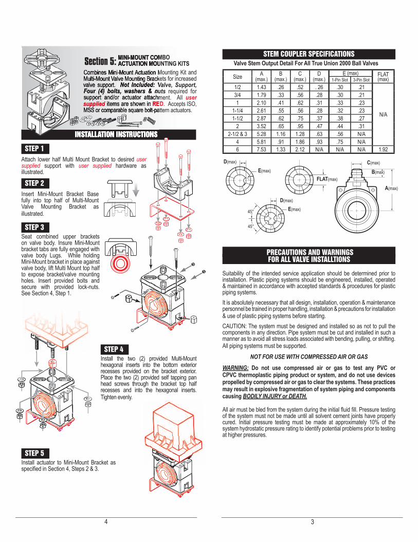
MINI-MOUNT COMBO ACTUATION MOUNTING KITSCombines Mini-Mount Actuation Mounting Kit and Multi-Mount Valve Mounting Brackets for increased valve support. Not Included: Valve, Support, Four (4) bolts, washers & nuts required for support and/or actuator attachment. All user supplied items are shown in RED. Accepts ISO, MSS or comparable square bolt-pattern actuators.
INSTALLATION INSTRUCTIONS
STEP 1 Attach lower half Multi Mount Bracket to desired user supplied support with user supplied hardware as illustrated.
STEP 2 Insert Mini-Mount Bracket Base fully into top half of Multi-Mount Valve Mounting Bracket as illustrated.
STEP 3 Seat combined upper brackets on valve body. Insure Mini-Mount bracket tabs are fully engaged with valve body Lugs. While holding Mini-Mount bracket in place against valve body, lift Multi Mount top half to expose bracket/valve mounting holes. Insert provided bolts and secure with provided lock-nuts. See Section 4, Step 1.
STEP 4 Install the two (2) provided Multi-Mount hexagonal inserts into the bottom exterior recesses provided on the bracket exterior. Place the two (2) provided self tapping pan head screws through the bracket top half recesses and into the hexagonal inserts. Tighten evenly.
STEP 5 Install actuator to Mini-Mount Bracket as specifi ed in Section 4, Steps 2 & 3.
Section 5: STEM COUPLER SPECIFICATIONS
PRECAUTIONS AND WARNINGS FOR ALL VALVE INSTALLTIONS
Suitability of the intended service application should be determined prior to installation. Plastic piping systems should be engineered, installed, operated & maintained in accordance with accepted standards & procedures for plastic piping systems.It is absolutely necessary that all design, installation, operation & maintenance personnel be trained in proper handling, installation & precautions for installation & use of plastic piping systems before starting.CAUTION: The system must be designed and installed so as not to pull the components in any direction. Pipe system must be cut and installed in such a manner as to avoid all stress loads associated with bending, pulling, or shifting. All piping systems must be supported.
NOT FOR USE WITH COMPRESSED AIR OR GASWARNING: Do not use compressed air or gas to test any PVC or CPVC thermoplastic piping product or system, and do not use devices propelled by compressed air or gas to clear the systems. These practices may result in explosive fragmentation of system piping and components causing BODILY INJURY or DEATH.
All air must be bled from the system during the initial fl uid fi ll. Pressure testing of the system must not be made until all solvent cement joints have properly cured. Initial pressure testing must be made at approximately 10% of the system hydrostatic pressure rating to identify potential problems prior to testing at higher pressures.
Size A(max.)
B(max.)
C(max.)
D(max.)
E (max) FLAT (max)1-Pin Slot 3-Pin Slot
1/2 1.43 .26 .52 . 26 .30 .21
N/A
3/4 1.79 .33 .56 .28 .30 .211 2.10 .41 .62 .31 .33 .23
1-1/4 2.61 .55 .56 .28 .32 .231-1/2 2.87 .62 .75 .37 .38 .27
2 3.52 .65 .95 .47 .44 .312-1/2 & 3 5.28 1.16 1.28 .63 .56 N/A
4 5.81 .91 1.86 .93 .75 N/A6 7.53 1.33 2.12 N/A N/A N/A 1.92
Valve Stem Output Detail For All True Union 2000 Ball Valves
D(max)
D(max)
E(max)
E(max)
C(max)
B(max)
A(max)
FLAT(max)
45°
45°