Embed Size (px)
Citation preview

BALDOR MN430 Explosion Proof Motors Manual http://www.manuallib.com/baldor/mn430-explosion-proof-motors-manual.html
This document is a supplement to the Baldor Installation and Operation Manual MN408. MN408 containsgeneral procedures that apply to NEMA/IEC type Baldor Motor products (hereinafter referred to as “theMotors”). For your protection, do not install, operate or attempt to perform maintenance procedures untilyou understand the WARNING and Caution statements.
ManualLib.com collects and classifies the global productinstrunction manuals to help users access anytime andanywhere, helping users make better use of products.
http://www.manuallib.com
Explosion Proof MotorsNEMA 180-449 (IEC 112S-280H)
Installation & Operating Manual
12/11 MN430
This Manual:http://www.manuallib.com/baldor/mn430-explosion-proof-motors-manual.html

Any trademarks used in this manual are the property of their respective owners.
This Manual:http://www.manuallib.com/baldor/mn430-explosion-proof-motors-manual.html
Table of Contents
Table of Contents iMN430
Section 1General Information 1−1. . . . . . . . . . . . . . . . . . . . . . . . . . . . . . . . . . . . . . . . . . . . . . . . . . . . . . . . . . . . . . . . . . . . . . . . . . . . . . .
Introduction 1−1. . . . . . . . . . . . . . . . . . . . . . . . . . . . . . . . . . . . . . . . . . . . . . . . . . . . . . . . . . . . . . . . . . . . . . . . . . . . . . . . . . .
Safety Notice 1−6. . . . . . . . . . . . . . . . . . . . . . . . . . . . . . . . . . . . . . . . . . . . . . . . . . . . . . . . . . . . . . . . . . . . . . . . . . . . . . . . . .
Receiving 1−8. . . . . . . . . . . . . . . . . . . . . . . . . . . . . . . . . . . . . . . . . . . . . . . . . . . . . . . . . . . . . . . . . . . . . . . . . . . . . . . . . . . . .
Handling 1−9. . . . . . . . . . . . . . . . . . . . . . . . . . . . . . . . . . . . . . . . . . . . . . . . . . . . . . . . . . . . . . . . . . . . . . . . . . . . . . . . . . . . . .
Storage 1−9. . . . . . . . . . . . . . . . . . . . . . . . . . . . . . . . . . . . . . . . . . . . . . . . . . . . . . . . . . . . . . . . . . . . . . . . . . . . . . . . . . . . . . .
Preparation for Storage 1−9. . . . . . . . . . . . . . . . . . . . . . . . . . . . . . . . . . . . . . . . . . . . . . . . . . . . . . . . . . . . . . . . . . . . .
Removal From Storage 1−10. . . . . . . . . . . . . . . . . . . . . . . . . . . . . . . . . . . . . . . . . . . . . . . . . . . . . . . . . . . . . . . . . . . . .
Warranty 1−10. . . . . . . . . . . . . . . . . . . . . . . . . . . . . . . . . . . . . . . . . . . . . . . . . . . . . . . . . . . . . . . . . . . . . . . . . . . . . . . . . . . . . .
Section 2Installation & Operation 2−1. . . . . . . . . . . . . . . . . . . . . . . . . . . . . . . . . . . . . . . . . . . . . . . . . . . . . . . . . . . . . . . . . . . . . . . . . . .
Installation and use 2−1. . . . . . . . . . . . . . . . . . . . . . . . . . . . . . . . . . . . . . . . . . . . . . . . . . . . . . . . . . . . . . . . . . . . . . . . . . . .
Mounting 2−1. . . . . . . . . . . . . . . . . . . . . . . . . . . . . . . . . . . . . . . . . . . . . . . . . . . . . . . . . . . . . . . . . . . . . . . . . . . . . . . . . . . . .
Frame Mounting Holes 2−2. . . . . . . . . . . . . . . . . . . . . . . . . . . . . . . . . . . . . . . . . . . . . . . . . . . . . . . . . . . . . . . . . . . . .
Alignment 2−2. . . . . . . . . . . . . . . . . . . . . . . . . . . . . . . . . . . . . . . . . . . . . . . . . . . . . . . . . . . . . . . . . . . . . . . . . . . . . . . . . . . . .
Doweling & Bolting 2−2. . . . . . . . . . . . . . . . . . . . . . . . . . . . . . . . . . . . . . . . . . . . . . . . . . . . . . . . . . . . . . . . . . . . . . . . . . . . .
Guarding 2−3. . . . . . . . . . . . . . . . . . . . . . . . . . . . . . . . . . . . . . . . . . . . . . . . . . . . . . . . . . . . . . . . . . . . . . . . . . . . . . . . .
Connection of AC Power Supply 2−3. . . . . . . . . . . . . . . . . . . . . . . . . . . . . . . . . . . . . . . . . . . . . . . . . . . . . . . . . . . . . . . . .
Connection of Additional Devices 2−4. . . . . . . . . . . . . . . . . . . . . . . . . . . . . . . . . . . . . . . . . . . . . . . . . . . . . . . . . . . .
Options of Rotation Control (Direction and Speed) 2−4. . . . . . . . . . . . . . . . . . . . . . . . . . . . . . . . . . . . . . . . . . . . .
Connection Diagrams 2−5. . . . . . . . . . . . . . . . . . . . . . . . . . . . . . . . . . . . . . . . . . . . . . . . . . . . . . . . . . . . . . . . . . . . . .
Lubrication Procedure 2−7. . . . . . . . . . . . . . . . . . . . . . . . . . . . . . . . . . . . . . . . . . . . . . . . . . . . . . . . . . . . . . . . . . . . . . . . . .
Start−up and Commencement Of Operation of Electrical Motors 2−7. . . . . . . . . . . . . . . . . . . . . . . . . . . . . . . . . . . . .
First Time Start Up 2−7. . . . . . . . . . . . . . . . . . . . . . . . . . . . . . . . . . . . . . . . . . . . . . . . . . . . . . . . . . . . . . . . . . . . . . . . . . . . .
Coupled Start Up 2−7. . . . . . . . . . . . . . . . . . . . . . . . . . . . . . . . . . . . . . . . . . . . . . . . . . . . . . . . . . . . . . . . . . . . . . . . . . . . . .
Jogging and Repeated Starts 2−7. . . . . . . . . . . . . . . . . . . . . . . . . . . . . . . . . . . . . . . . . . . . . . . . . . . . . . . . . . . . . . . . . . . .
Repair 2−8. . . . . . . . . . . . . . . . . . . . . . . . . . . . . . . . . . . . . . . . . . . . . . . . . . . . . . . . . . . . . . . . . . . . . . . . . . . . . . . . . . . . . . . .
Section 3Maintenance & Troubleshooting 3−1. . . . . . . . . . . . . . . . . . . . . . . . . . . . . . . . . . . . . . . . . . . . . . . . . . . . . . . . . . . . . . . . . . . .
General Inspection 3−1. . . . . . . . . . . . . . . . . . . . . . . . . . . . . . . . . . . . . . . . . . . . . . . . . . . . . . . . . . . . . . . . . . . . . . . . . . . . .
Relubrication & Bearings 3−1. . . . . . . . . . . . . . . . . . . . . . . . . . . . . . . . . . . . . . . . . . . . . . . . . . . . . . . . . . . . . . . . . . . . . . . .
Type of Grease 3−1. . . . . . . . . . . . . . . . . . . . . . . . . . . . . . . . . . . . . . . . . . . . . . . . . . . . . . . . . . . . . . . . . . . . . . . . . . . .
Relubrication Intervals 3−2. . . . . . . . . . . . . . . . . . . . . . . . . . . . . . . . . . . . . . . . . . . . . . . . . . . . . . . . . . . . . . . . . . . . . .
Relubrication Procedure 3−3. . . . . . . . . . . . . . . . . . . . . . . . . . . . . . . . . . . . . . . . . . . . . . . . . . . . . . . . . . . . . . . . . . . .
Troubleshooting Chart 3−5. . . . . . . . . . . . . . . . . . . . . . . . . . . . . . . . . . . . . . . . . . . . . . . . . . . . . . . . . . . . . . . . . . . . . . . . . .
Suggested bearing and winding RTD setting guidelines for Non−Hazardous Locations ONLY 3−6. . . . . . . . . . . .
Appendix A A−1. . . . . . . . . . . . . . . . . . . . . . . . . . . . . . . . . . . . . . . . . . . . . . . . . . . . . . . . . . . . . . . . . . . . . . . . . . . . . . . . . . . . . . .
This Manual:http://www.manuallib.com/baldor/mn430-explosion-proof-motors-manual.html

Section 1General Information
ii Table of Contents MN430
This Manual:http://www.manuallib.com/baldor/mn430-explosion-proof-motors-manual.html
Section 1General Information
General Information 1−1MN430
IntroductionThis document is a supplement to the Baldor Installation and Operation Manual MN408. MN408 containsgeneral procedures that apply to NEMA/IEC type Baldor Motor products (hereinafter referred to as “theMotors”). For your protection, do not install, operate or attempt to perform maintenance procedures untilyou understand the WARNING and Caution statements.Before you install, operate or perform maintenance, become familiar with the following documents (withregard for specific application area:
GOST R IEC 60079-0:2007 Explosive atmospheres. Part 0. Equipment. General requirements.GOST R 52350.19:2007(IEC 60079-19:2006)
Explosive atmospheres. Equipment repair, overhaul and reclamation.
GOST 12.1.030-81 Occupational safety standards system. Electric safety. Protective grounding. Neutral grounding.
GOST 21130-75 Electrical devices. Earth terminals and earth signs.PB 05-618-03 Safety rules in coal mines.PB 03-553-03 Uniform safety rules for the development of ore, non-metallic minerals and placer
deposits of minerals by underground technique.PB 08-624-03 Safety rules in the oil and gas industry.PB 09-540-03 General explosion safety rules for explosion-fire hazard chemical, petrochemical and oil
refining industries.PTE Electrical equipment operating instructions. Approved by Order No. 6 of the Ministry of
Energy of the Russian Federation dated January 13, 2003.PUE Installation requirements for electrical equipment and installations. Approved by Order
No. 204 of the Ministry of Energy of the Russian Federation dated July 08, 2002.
I Description & OperationI.1 Product Description & Operation
I.1.1 Product Scope of Application
NEMA/IEC motors are used as power elements of the electric drives.NEMA/IEC motors have explosion-proof performance for three groups, i.e., I, II (subgroup IIB), and III(according to GOST R IEC 60079-0:2007).Scope of application:- Underground coal mines and pits and their above-ground buildings which are hazardous for firedamp
and/or combustible dust according to the explosion protection marking (group I motors);- Class 1 and 2 explosive zones of the buildings and outdoor installations according to the explosion
protection marking (group II motors);- Zones hazardous for ignition of combustible dust of classes 21 and 22 according to the explosion
protection marking (group III motors).Primary technical items for installing NEMA/IEC motors of group I:
- Pumps; - Conveyors; - Fans; - Roof bolter;- Drives for cutting, crushing, and grinding; - Travel drives.
Primary technical items for installing NEMA/IEC motors of group II:- Pumps; - Turbine starters; - Valve, shutter, and damper actuators; - Fans.
Primary technical items for installing NEMA/IEC motors of group III:- Conveyors; - Drives for cutting, crushing, and grinding - Fans;.
I.1.2 Technical parameters
NEMA 180-440 frame range motors (IEC equivalent designations 112S-280H) have the followingspecifications:
I.1.2.1 Levels and types of explosion protection
For NEMA/IEC motors of Group I – Ex d I Mb X;For NEMA/IEC motors of Group II (subgroup IIB) – Ex d IIB Gb T3…T4…T5 X; Ex d e IIB GbT3…T4…T5 X;
This Manual:http://www.manuallib.com/baldor/mn430-explosion-proof-motors-manual.html
1−2 General Information MN430
For NEMA/IEC motors of Group III –- Ex t IIIC T100�C … T135�C… T200�C Db X IP6X.
I.1.2.2 Ingress protection according to GOST 14254-96
For NEMA/IEC motors of Group I and For NEMA/IEC motors of Group II (subgroup IIB) – IP54, or higher.For NEMA/IEC motors of Group III – IP6X.
I.1.2.3 Electrical products group of guard against personnel electrical shock according to GOST 12.2.007.0-75
I.1.2.4 Ambient temperature range
Ambient temperature range for NEMA/IEC motors is –20 … +65C.I.1.2.5 Maximum supply voltage
Maximum AC supply voltage is 7200 V.Power can be supplied directly from an electrical outlet or via an inverter.
I.1.2.6 Nominal rating power
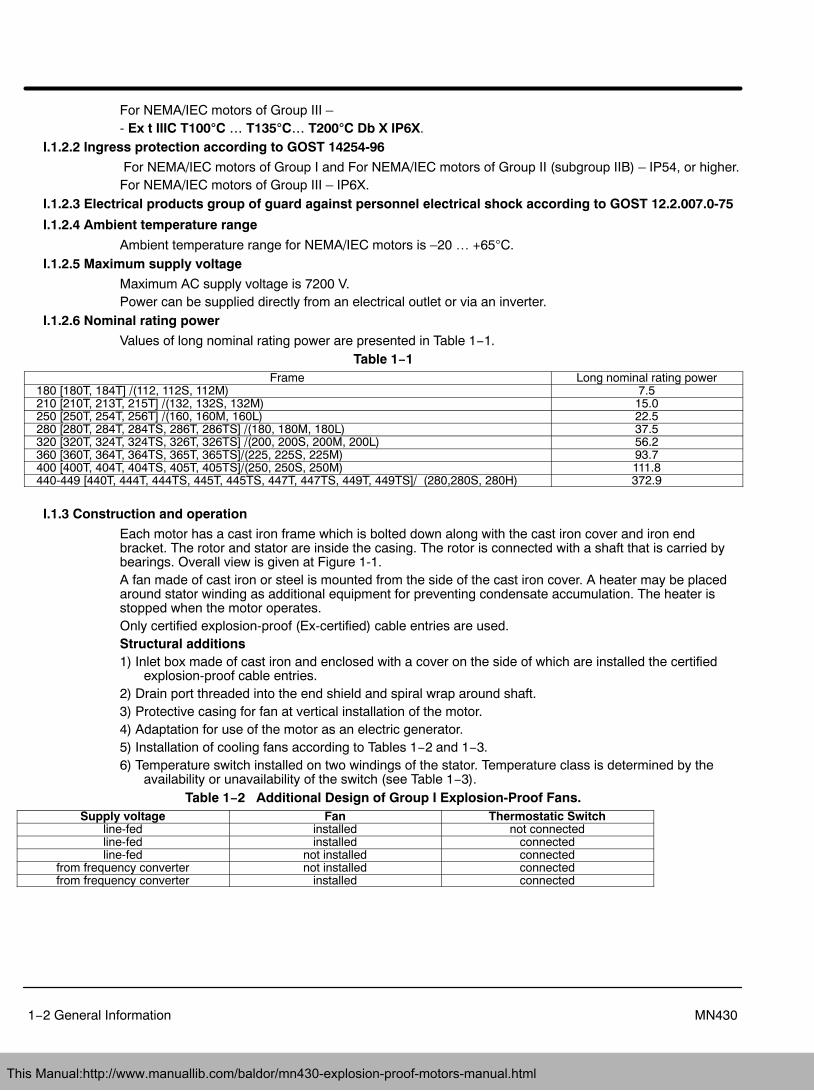
Values of long nominal rating power are presented in Table 1−1.Table 1−1
Frame Long nominal rating power180 [180T, 184T] /(112, 112S, 112M) 7.5210 [210T, 213T, 215T] /(132, 132S, 132M) 15.0250 [250T, 254T, 256T] /(160, 160M, 160L) 22.5280 [280T, 284T, 284TS, 286T, 286TS] /(180, 180M, 180L) 37.5320 [320T, 324T, 324TS, 326T, 326TS] /(200, 200S, 200M, 200L) 56.2360 [360T, 364T, 364TS, 365T, 365TS]/(225, 225S, 225M) 93.7400 [400T, 404T, 404TS, 405T, 405TS]/(250, 250S, 250M) 111.8440-449 [440T, 444T, 444TS, 445T, 445TS, 447T, 447TS, 449T, 449TS]/ (280,280S, 280H) 372.9
I.1.3 Construction and operation
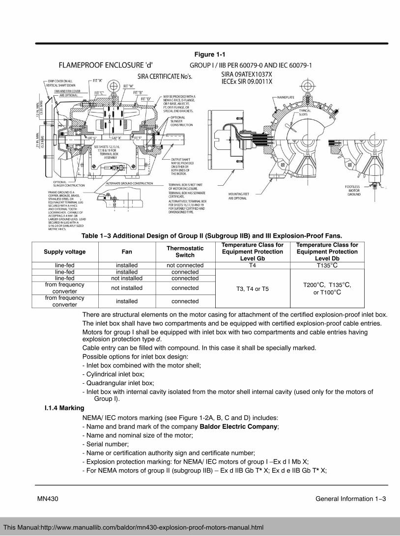
Each motor has a cast iron frame which is bolted down along with the cast iron cover and iron endbracket. The rotor and stator are inside the casing. The rotor is connected with a shaft that is carried bybearings. Overall view is given at Figure 1-1.A fan made of cast iron or steel is mounted from the side of the cast iron cover. A heater may be placedaround stator winding as additional equipment for preventing condensate accumulation. The heater isstopped when the motor operates.Only certified explosion-proof (Ex-certified) cable entries are used.Structural additions1) Inlet box made of cast iron and enclosed with a cover on the side of which are installed the certified
explosion-proof cable entries.2) Drain port threaded into the end shield and spiral wrap around shaft.3) Protective casing for fan at vertical installation of the motor.4) Adaptation for use of the motor as an electric generator.5) Installation of cooling fans according to Tables 1−2 and 1−3.6) Temperature switch installed on two windings of the stator. Temperature class is determined by the
availability or unavailability of the switch (see Table 1−3).Table 1−2 Additional Design of Group I Explosion-Proof Fans.
Supply voltage Fan Thermostatic Switchline-fed installed not connectedline-fed installed connectedline-fed not installed connected
from frequency converter not installed connectedfrom frequency converter installed connected
This Manual:http://www.manuallib.com/baldor/mn430-explosion-proof-motors-manual.html
General Information 1−3MN430
Figure 1-1
Table 1−3 Additional Design of Group II (Subgroup IIB) and III Explosion-Proof Fans.
Supply voltage Fan ThermostaticSwitch
Temperature Class forEquipment Protection
Level Gb
Temperature Class forEquipment Protection
Level Dbline-fed installed not connected T4 T135Cline-fed installed connected
T3, T4 or T5T200C, T135C,
or T100C
line-fed not installed connectedfrom frequency
converternot installed connected
from frequencyconverter installed connected
There are structural elements on the motor casing for attachment of the certified explosion-proof inlet box.The inlet box shall have two compartments and be equipped with certified explosion-proof cable entries.Motors for group I shall be equipped with inlet box with two compartments and cable entries havingexplosion protection type d.Cable entry can be filled with compound. In this case it shall be specially marked.Possible options for inlet box design:- Inlet box combined with the motor shell;- Cylindrical inlet box;- Quadrangular inlet box;- Inlet box with internal cavity isolated from the motor shell internal cavity (used only for the motors of
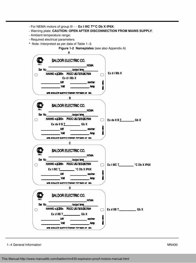
Group I).I.1.4 Marking
NEMA/ IEC motors marking (see Figure 1-2A, B, C and D) includes:- Name and brand mark of the company Baldor Electric Company;- Name and nominal size of the motor;- Serial number;- Name or certification authority sign and certificate number;- Explosion protection marking: for NEMA/ IEC motors of group I –Ex d I Mb X;- For NEMA motors of group II (subgroup IIB) – Ex d IIB Gb T* X; Ex d e IIB Gb T* X;
This Manual:http://www.manuallib.com/baldor/mn430-explosion-proof-motors-manual.html
1−4 General Information MN430
- For NEMA motors of group III – - Ex t IIIC T*�C Db X IP6X;- Warning plate: CAUTION: OPEN AFTER DISCONNECTION FROM MAINS SUPPLY;- Ambient temperature range;- Required electrical parameters.* Note: Interpreted as per data of Table 1−3.
Figure 1-2 Nameplates (see also Appendix A)
Ex d I Mb X
Ex de II B T Gb X
A
Ex d I Mb X
B
Ex de II B T Gb X
Ex t IIIC T �C Db X IP6X
C
Ex t IIIC T �C Db X IP6X
Ex d IIB T Gb X
D
Ex d IIB T Gb X
This Manual:http://www.manuallib.com/baldor/mn430-explosion-proof-motors-manual.html
General Information 1−5MN430
II Intended useII.1 Operating limits
II.1.1 Conditions of use
Special conditions for ensuring operational safety, marked with an ‘X’ placed after explosion protectionmarking indicates that at operation of explosion protected motors of types NEMA 180-449 /(IEC112S-280H) it is necessary to observe the following safety requirements:6.1. The motors shall be equipped either with corresponding inlet boxes of Baldor Electric Company
manufacture or other explosion protected boxes of corresponding design and certified as per GOST Rwith marking that corresponds to motors explosion protection marking.
6.2. The motor design shall correspond to the temperature class specified in markings according to theTables 1−2 and 1−3.
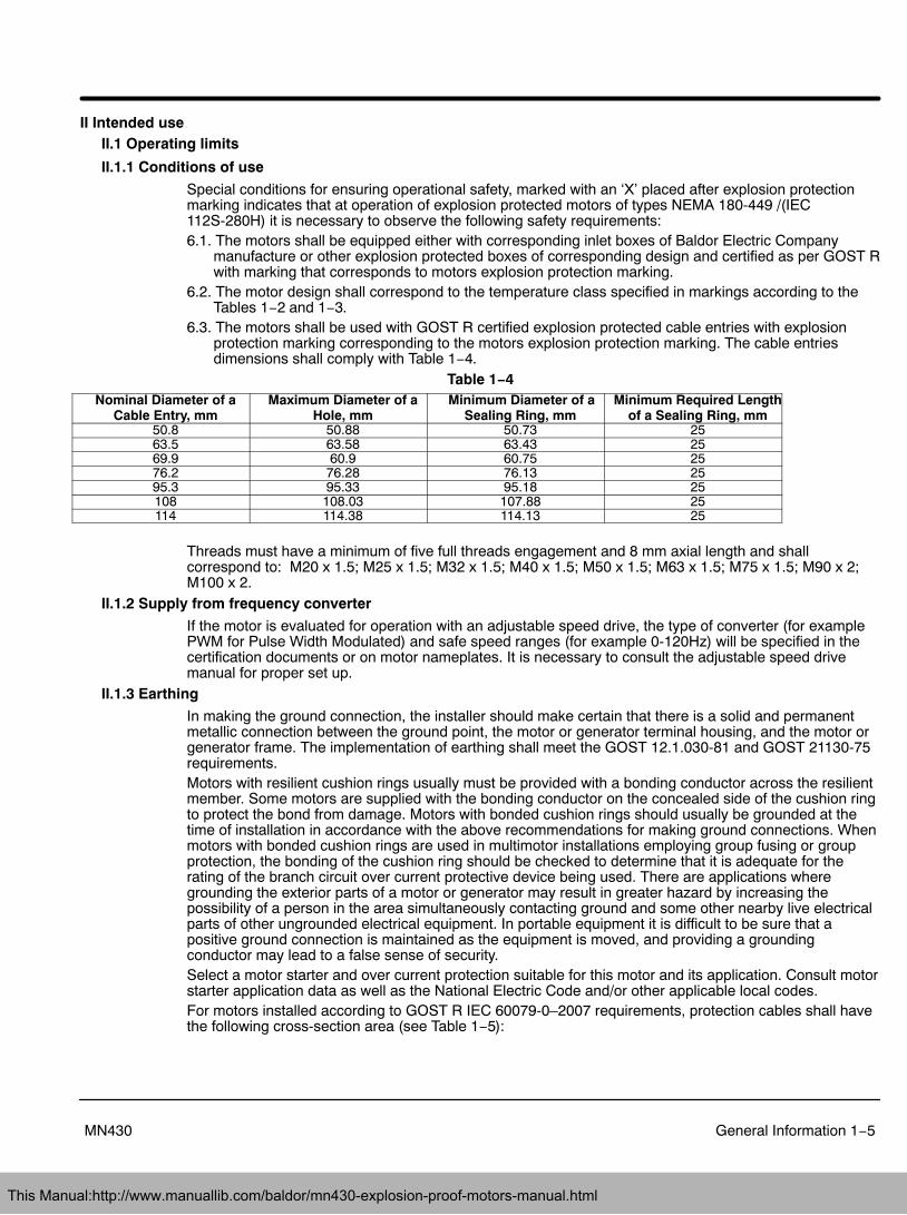
6.3. The motors shall be used with GOST R certified explosion protected cable entries with explosionprotection marking corresponding to the motors explosion protection marking. The cable entriesdimensions shall comply with Table 1−4.
Table 1−4Nominal Diameter of a
Cable Entry, mmMaximum Diameter of a
Hole, mmMinimum Diameter of a
Sealing Ring, mmMinimum Required Length
of a Sealing Ring, mm50.8 50.88 50.73 2563.5 63.58 63.43 2569.9 60.9 60.75 2576.2 76.28 76.13 2595.3 95.33 95.18 25108 108.03 107.88 25114 114.38 114.13 25
Threads must have a minimum of five full threads engagement and 8 mm axial length and shallcorrespond to: M20 x 1.5; M25 x 1.5; M32 x 1.5; M40 x 1.5; M50 x 1.5; M63 x 1.5; M75 x 1.5; M90 x 2;M100 x 2.
II.1.2 Supply from frequency converter
If the motor is evaluated for operation with an adjustable speed drive, the type of converter (for examplePWM for Pulse Width Modulated) and safe speed ranges (for example 0-120Hz) will be specified in thecertification documents or on motor nameplates. It is necessary to consult the adjustable speed drivemanual for proper set up.
II.1.3 Earthing
In making the ground connection, the installer should make certain that there is a solid and permanentmetallic connection between the ground point, the motor or generator terminal housing, and the motor orgenerator frame. The implementation of earthing shall meet the GOST 12.1.030-81 and GOST 21130-75requirements.Motors with resilient cushion rings usually must be provided with a bonding conductor across the resilientmember. Some motors are supplied with the bonding conductor on the concealed side of the cushion ringto protect the bond from damage. Motors with bonded cushion rings should usually be grounded at thetime of installation in accordance with the above recommendations for making ground connections. Whenmotors with bonded cushion rings are used in multimotor installations employing group fusing or groupprotection, the bonding of the cushion ring should be checked to determine that it is adequate for therating of the branch circuit over current protective device being used. There are applications wheregrounding the exterior parts of a motor or generator may result in greater hazard by increasing thepossibility of a person in the area simultaneously contacting ground and some other nearby live electricalparts of other ungrounded electrical equipment. In portable equipment it is difficult to be sure that apositive ground connection is maintained as the equipment is moved, and providing a groundingconductor may lead to a false sense of security.Select a motor starter and over current protection suitable for this motor and its application. Consult motorstarter application data as well as the National Electric Code and/or other applicable local codes.For motors installed according to GOST R IEC 60079-0–2007 requirements, protection cables shall havethe following cross-section area (see Table 1−5):
This Manual:http://www.manuallib.com/baldor/mn430-explosion-proof-motors-manual.html
1−6 General Information MN430
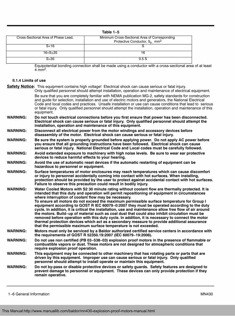
Table 1−5Cross-Sectional Area of Phase Lead, Minimum Cross-Sectional Area of Corresponding
Protective Conductor, Sp , mm2
S<16 S
16<S<35 16
S>35 0.5 S
Equipotential bonding connection shall be made using a conductor with a cross-sectional area of at least4 mm2.
II.1.4 Limits of use
Safety Notice: This equipment contains high voltage! Electrical shock can cause serious or fatal injury. Only qualified personnel should attempt installation, operation and maintenance of electrical equipment.Be sure that you are completely familiar with NEMA publication MG-2, safety standards for constructionand guide for selection, installation and use of electric motors and generators, the National ElectricalCode and local codes and practices. Unsafe installation or use can cause conditions that lead to seriousor fatal injury. Only qualified personnel should attempt the installation, operation and maintenance of thisequipment.
WARNING: Do not touch electrical connections before you first ensure that power has been disconnected.Electrical shock can cause serious or fatal injury. Only qualified personnel should attempt theinstallation, operation and maintenance of this equipment.
WARNING: Disconnect all electrical power from the motor windings and accessory devices beforedisassembly of the motor. Electrical shock can cause serious or fatal injury.
WARNING: Be sure the system is properly grounded before applying power. Do not apply AC power beforeyou ensure that all grounding instructions have been followed. Electrical shock can causeserious or fatal injury. National Electrical Code and Local codes must be carefully followed.
WARNING: Avoid extended exposure to machinery with high noise levels. Be sure to wear ear protectivedevices to reduce harmful effects to your hearing.
WARNING: Avoid the use of automatic reset devices if the automatic restarting of equipment can behazardous to personnel or equipment.
WARNING: Surface temperatures of motor enclosures may reach temperatures which can cause discomfortor injury to personnel accidentally coming into contact with hot surfaces. When installing,protection should be provided by the user to protect against accidental contact with hot surfaces.Failure to observe this precaution could result in bodily injury.
WARNING: Water Cooled Motors with S2 30 minute rating without coolant flow are thermally protected. It isintended that this duty and operation will permit repositioning of equipment in circumstanceswhere interruption of coolant flow may be necessary. To ensure all motors do not exceed the maximum permissible surface temperature for Group Iequipment according to GOST R IEC 60079−0:2007 they must be operated according to the dutycycle. In addition, it is critical the installation, use and maintenance allow free flow of air aroundthe motors. Build−up of material such as coal dust that could also inhibit circulation must beremoved before operation with this duty cycle. In addition, it is necessary to connect the motorthermal protection devices which act as a secondary measure to provide additional assurancethat the permissible maximum surface temperature is not exceeded.
WARNING: Motors must only be serviced by a Baldor authorized certified service centers in accordance withthe requirements of GOST R 52350.19:2007 (IEC 60079−19:2006).
WARNING: Do not use non certified (PB 03−538−03) explosion proof motors in the presence of flammable orcombustible vapors or dust. These motors are not designed for atmospheric conditions thatrequire explosion proof operation.
WARNING: This equipment may be connected to other machinery that has rotating parts or parts that aredriven by this equipment. Improper use can cause serious or fatal injury. Only qualifiedpersonnel should attempt to install operate or maintain this equipment.
WARNING: Do not by-pass or disable protective devices or safety guards. Safety features are designed toprevent damage to personnel or equipment. These devices can only provide protection if theyremain operative.
This Manual:http://www.manuallib.com/baldor/mn430-explosion-proof-motors-manual.html
General Information 1−7MN430
Safety Notice ContinuedWARNING: Be sure the load is properly coupled to the motor shaft before applying power. The shaft key
must be fully captive by the load device. Improper coupling can cause harm to personnel orequipment if the load decouples from the shaft during operation.
WARNING: UL Listed motors must only be serviced by UL Approved Authorized Baldor Service Centers ifthese motors are to be returned to a hazardous and/or explosive atmosphere.
WARNING: Thermostat contacts automatically reset when the motor has slightly cooled down. To preventinjury or damage, the control circuit should be designed so that automatic starting of the motor isnot possible when the thermostat resets.
WARNING: Use proper care and procedures that are safe during handling, lifting, installing, operating andmaintaining operations. Improper methods may cause muscle strain or other harm.
WARNING: Pacemaker danger − Magnetic and electromagnetic fields in the vicinity of current carryingcarrying conductors and permanent magnet motors can result result in a serious health hazard topersons with cardiac pacemakers, metal implants, and hearing aids. To avoid risk, stay way fromthe area surrounding a permanent magnet motor.
WARNING: Before performing any motor maintenance procedure, be sure that the equipment connected tothe motor shaft cannot cause shaft rotation. If the load can cause shaft rotation, disconnect theload from the motor shaft before maintenance is performed. Unexpected mechanical rotation ofthe motor parts can cause injury or motor damage.
WARNING: Do not use non UL/CSA listed explosion proof motors in the presence of flammable orcombustible vapors or dust. These motors are not designed for atmospheric conditions thatrequire explosion proof operation.
WARNING: Motors that are to be used in flammable and/or explosive atmospheres must display the UL labelon the nameplate along with CSA listed logo. Specific service conditions for these motors aredefined in NFPA 70 (NEC) Article 500.
WARNING: Guards must be installed for rotating parts such as couplings, pulleys, external fans, and unusedshaft extensions, should be permanently guarded to prevent accidental contact by personnel.Accidental contact with body parts or clothing can cause serious or fatal injury.
Caution: To prevent premature equipment failure or damage, only qualified maintenance personnel shouldperform maintenance.
Caution: Do not over tension belts. Excess tension may damage the motor or driven equipment.Caution: Do not over−lubricate motor as this may cause premature bearing failure.Caution: Do not lift the motor and its driven load by the motor lifting hardware. The motor lifting hardware
is adequate for lifting only the motor. Disconnect the load (gears, pumps, compressors, or otherdriven equipment) from the motor shaft before lifting the motor.
Caution: If eye bolts are used for lifting a motor, be sure they are securely tightened. The lifting directionshould not exceed a 20 angle from the shank of the eye bolt or lifting lug. Excessive liftingangles can cause damage.
Caution: To prevent equipment damage, be sure that the electrical service is not capable of delivering morethan the maximum motor rated amps listed on the rating plate.
Caution: If a HI POT test (High Potential Insulation test) must be performed, follow the precautions andprocedure in NEMA MG1 and MG2 standards to avoid equipment damage.
Caution: The space heaters are designed to operate at or below the maximum surface temperature statedon the nameplate. If the marked ambient and/or voltage are exceeded this maximum surfacetemperature can be exceeded and can damage the motor windings. If applied in a division 2 orzone 2 environment this excessive temperature may cause ignition of hazardous materials.
This Manual:http://www.manuallib.com/baldor/mn430-explosion-proof-motors-manual.html
1−8 General Information MN430
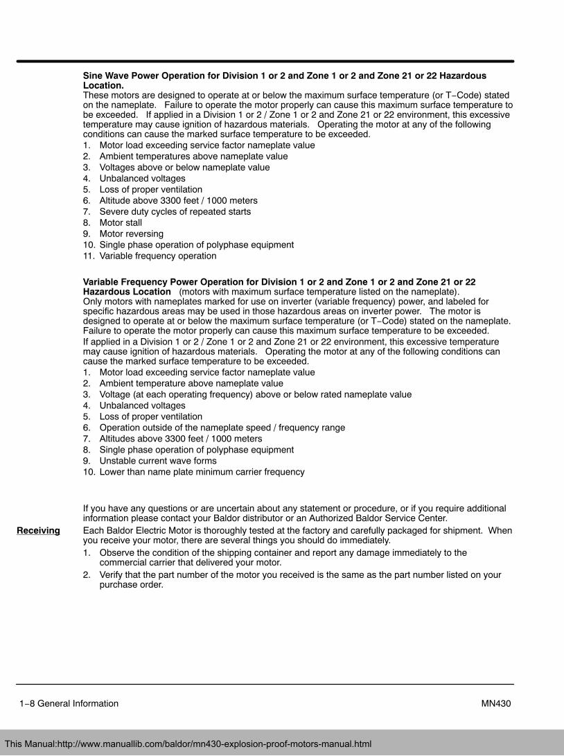
Sine Wave Power Operation for Division 1 or 2 and Zone 1 or 2 and Zone 21 or 22 HazardousLocation.These motors are designed to operate at or below the maximum surface temperature (or T−Code) statedon the nameplate. Failure to operate the motor properly can cause this maximum surface temperature tobe exceeded. If applied in a Division 1 or 2 / Zone 1 or 2 and Zone 21 or 22 environment, this excessivetemperature may cause ignition of hazardous materials. Operating the motor at any of the followingconditions can cause the marked surface temperature to be exceeded.1. Motor load exceeding service factor nameplate value2. Ambient temperatures above nameplate value3. Voltages above or below nameplate value4. Unbalanced voltages5. Loss of proper ventilation6. Altitude above 3300 feet / 1000 meters7. Severe duty cycles of repeated starts8. Motor stall9. Motor reversing10. Single phase operation of polyphase equipment11. Variable frequency operation
Variable Frequency Power Operation for Division 1 or 2 and Zone 1 or 2 and Zone 21 or 22Hazardous Location (motors with maximum surface temperature listed on the nameplate).Only motors with nameplates marked for use on inverter (variable frequency) power, and labeled forspecific hazardous areas may be used in those hazardous areas on inverter power. The motor isdesigned to operate at or below the maximum surface temperature (or T−Code) stated on the nameplate.Failure to operate the motor properly can cause this maximum surface temperature to be exceeded.If applied in a Division 1 or 2 / Zone 1 or 2 and Zone 21 or 22 environment, this excessive temperaturemay cause ignition of hazardous materials. Operating the motor at any of the following conditions cancause the marked surface temperature to be exceeded.1. Motor load exceeding service factor nameplate value2. Ambient temperature above nameplate value3. Voltage (at each operating frequency) above or below rated nameplate value4. Unbalanced voltages5. Loss of proper ventilation6. Operation outside of the nameplate speed / frequency range7. Altitudes above 3300 feet / 1000 meters8. Single phase operation of polyphase equipment9. Unstable current wave forms10. Lower than name plate minimum carrier frequency
If you have any questions or are uncertain about any statement or procedure, or if you require additionalinformation please contact your Baldor distributor or an Authorized Baldor Service Center.
Receiving Each Baldor Electric Motor is thoroughly tested at the factory and carefully packaged for shipment. Whenyou receive your motor, there are several things you should do immediately.1. Observe the condition of the shipping container and report any damage immediately to the
commercial carrier that delivered your motor.2. Verify that the part number of the motor you received is the same as the part number listed on your
purchase order.
This Manual:http://www.manuallib.com/baldor/mn430-explosion-proof-motors-manual.html
General Information 1−9MN430
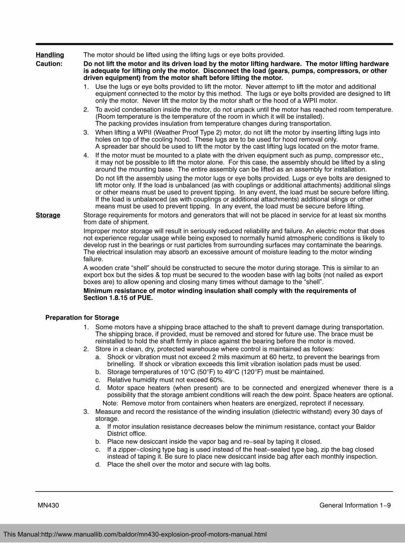
Handling The motor should be lifted using the lifting lugs or eye bolts provided.Caution: Do not lift the motor and its driven load by the motor lifting hardware. The motor lifting hardware
is adequate for lifting only the motor. Disconnect the load (gears, pumps, compressors, or otherdriven equipment) from the motor shaft before lifting the motor.1. Use the lugs or eye bolts provided to lift the motor. Never attempt to lift the motor and additional
equipment connected to the motor by this method. The lugs or eye bolts provided are designed to liftonly the motor. Never lift the motor by the motor shaft or the hood of a WPII motor.
2. To avoid condensation inside the motor, do not unpack until the motor has reached room temperature.(Room temperature is the temperature of the room in which it will be installed). The packing provides insulation from temperature changes during transportation.
3. When lifting a WPII (Weather Proof Type 2) motor, do not lift the motor by inserting lifting lugs intoholes on top of the cooling hood. These lugs are to be used for hood removal only. A spreader bar should be used to lift the motor by the cast lifting lugs located on the motor frame.
4. If the motor must be mounted to a plate with the driven equipment such as pump, compressor etc., it may not be possible to lift the motor alone. For this case, the assembly should be lifted by a slingaround the mounting base. The entire assembly can be lifted as an assembly for installation.Do not lift the assembly using the motor lugs or eye bolts provided. Lugs or eye bolts are designed tolift motor only. If the load is unbalanced (as with couplings or additional attachments) additional slingsor other means must be used to prevent tipping. In any event, the load must be secure before lifting.If the load is unbalanced (as with couplings or additional attachments) additional slings or othermeans must be used to prevent tipping. In any event, the load must be secure before lifting.
Storage Storage requirements for motors and generators that will not be placed in service for at least six monthsfrom date of shipment.Improper motor storage will result in seriously reduced reliability and failure. An electric motor that doesnot experience regular usage while being exposed to normally humid atmospheric conditions is likely todevelop rust in the bearings or rust particles from surrounding surfaces may contaminate the bearings. The electrical insulation may absorb an excessive amount of moisture leading to the motor windingfailure.A wooden crate “shell” should be constructed to secure the motor during storage. This is similar to anexport box but the sides & top must be secured to the wooden base with lag bolts (not nailed as exportboxes are) to allow opening and closing many times without damage to the “shell”.Minimum resistance of motor winding insulation shall comply with the requirements of Section 1.8.15 of PUE.
Preparation for Storage1. Some motors have a shipping brace attached to the shaft to prevent damage during transportation.
The shipping brace, if provided, must be removed and stored for future use. The brace must bereinstalled to hold the shaft firmly in place against the bearing before the motor is moved.
2. Store in a clean, dry, protected warehouse where control is maintained as follows:a. Shock or vibration must not exceed 2 mils maximum at 60 hertz, to prevent the bearings from
brinelling. If shock or vibration exceeds this limit vibration isolation pads must be used.b. Storage temperatures of 10C (50F) to 49C (120F) must be maintained.c. Relative humidity must not exceed 60%.d. Motor space heaters (when present) are to be connected and energized whenever there is a
possibility that the storage ambient conditions will reach the dew point. Space heaters are optional.Note: Remove motor from containers when heaters are energized, reprotect if necessary.
3. Measure and record the resistance of the winding insulation (dielectric withstand) every 30 days ofstorage.a. If motor insulation resistance decreases below the minimum resistance, contact your Baldor
District office.b. Place new desiccant inside the vapor bag and re−seal by taping it closed.c. If a zipper−closing type bag is used instead of the heat−sealed type bag, zip the bag closed
instead of taping it. Be sure to place new desiccant inside bag after each monthly inspection.d. Place the shell over the motor and secure with lag bolts.
This Manual:http://www.manuallib.com/baldor/mn430-explosion-proof-motors-manual.html
1−10 General Information MN430
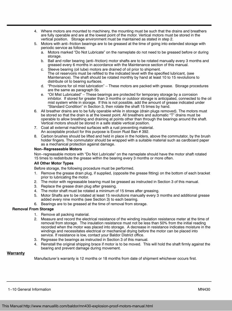
4. Where motors are mounted to machinery, the mounting must be such that the drains and breathersare fully operable and are at the lowest point of the motor. Vertical motors must be stored in thevertical position. Storage environment must be maintained as stated in step 2.
5. Motors with anti−friction bearings are to be greased at the time of going into extended storage withperiodic service as follows:a. Motors marked “Do Not Lubricate” on the nameplate do not need to be greased before or during
storage.b. Ball and roller bearing (anti−friction) motor shafts are to be rotated manually every 3 months and
greased every 6 months in accordance with the Maintenance section of this manual.c. Sleeve bearing (oil lube) motors are drained of oil prior to shipment.
The oil reservoirs must be refilled to the indicated level with the specified lubricant, (seeMaintenance). The shaft should be rotated monthly by hand at least 10 to 15 revolutions todistribute oil to bearing surfaces.
d. “Provisions for oil mist lubrication” – These motors are packed with grease. Storage proceduresare the same as paragraph 5b.
e. “Oil Mist Lubricated” – These bearings are protected for temporary storage by a corrosioninhibitor. If stored for greater than 3 months or outdoor storage is anticipated, connected to the oilmist system while in storage. If this is not possible, add the amount of grease indicated under“Standard Condition” in Section 3, then rotate the shaft 15 times by hand.
6. All breather drains are to be fully operable while in storage (drain plugs removed). The motors mustbe stored so that the drain is at the lowest point. All breathers and automatic “T” drains must beoperable to allow breathing and draining at points other than through the bearings around the shaft. Vertical motors should be stored in a safe stable vertical position.
7. Coat all external machined surfaces with a rust preventing material. An acceptable product for this purpose is Exxon Rust Ban # 392.
8. Carbon brushes should be lifted and held in place in the holders, above the commutator, by the brushholder fingers. The commutator should be wrapped with a suitable material such as cardboard paperas a mechanical protection against damage.
Non−Regreaseable MotorsNon−regreasable motors with “Do Not Lubricate” on the nameplate should have the motor shaft rotated15 times to redistribute the grease within the bearing every 3 months or more often.All Other Motor TypesBefore storage, the following procedure must be performed.1. Remove the grease drain plug, if supplied, (opposite the grease fitting) on the bottom of each bracket
prior to lubricating the motor.2. The motor with regreasable bearing must be greased as instructed in Section 3 of this manual.3. Replace the grease drain plug after greasing.4. The motor shaft must be rotated a minimum of 15 times after greasing.5. Motor Shafts are to be rotated at least 15 revolutions manually every 3 months and additional grease
added every nine months (see Section 3) to each bearing.6. Bearings are to be greased at the time of removal from storage.
Removal From Storage1. Remove all packing material.2. Measure and record the electrical resistance of the winding insulation resistance meter at the time of
removal from storage. The insulation resistance must not be less than 50% from the initial readingrecorded when the motor was placed into storage. A decrease in resistance indicates moisture in thewindings and necessitates electrical or mechanical drying before the motor can be placed intoservice. If resistance is low, contact your Baldor District office.
3. Regrease the bearings as instructed in Section 3 of this manual.4. Reinstall the original shipping brace if motor is to be moved. This will hold the shaft firmly against the
bearing and prevent damage during movement.Warranty
Manufacturer’s warranty is 12 months or 18 months from date of shipment whichever occurs first.
This Manual:http://www.manuallib.com/baldor/mn430-explosion-proof-motors-manual.html
Section 2Installation & Operation
Installation & Operation 2−1MN430
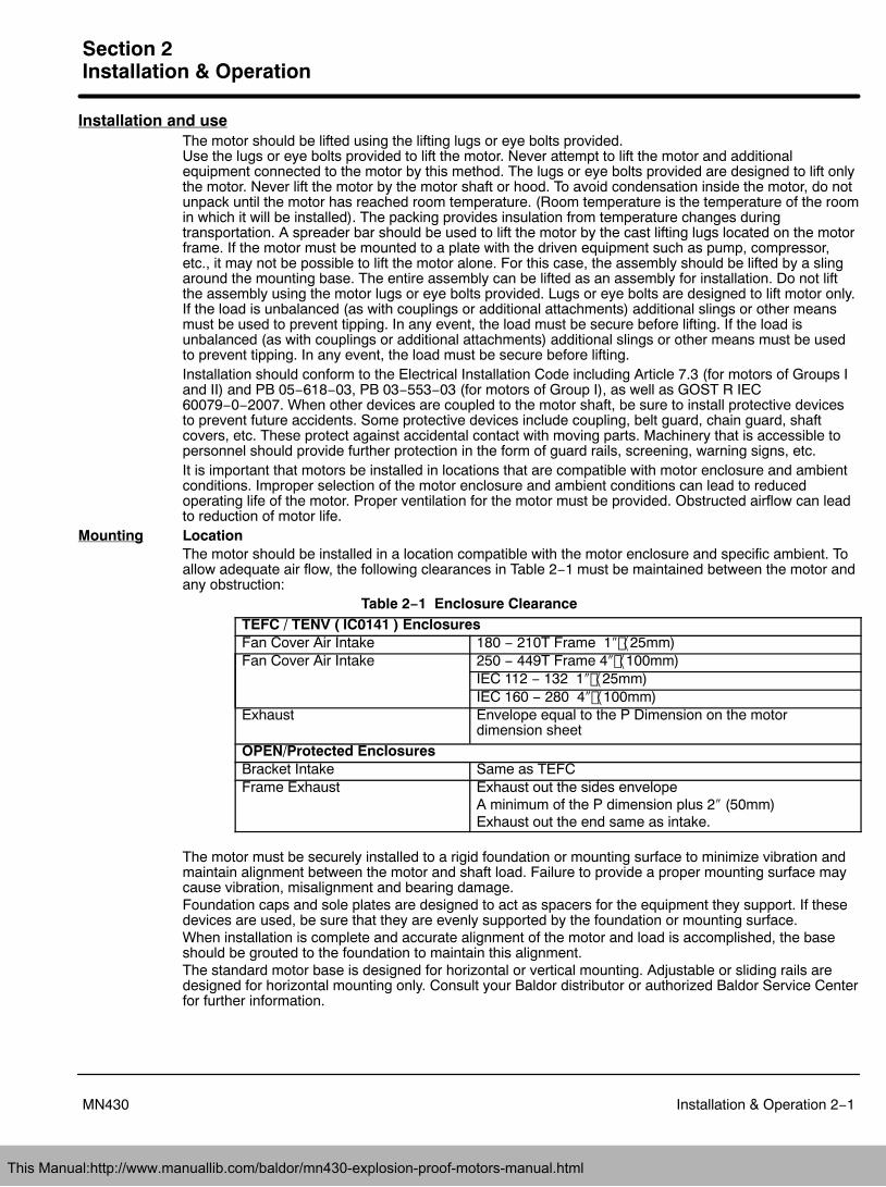
Installation and useThe motor should be lifted using the lifting lugs or eye bolts provided. Use the lugs or eye bolts provided to lift the motor. Never attempt to lift the motor and additionalequipment connected to the motor by this method. The lugs or eye bolts provided are designed to lift onlythe motor. Never lift the motor by the motor shaft or hood. To avoid condensation inside the motor, do notunpack until the motor has reached room temperature. (Room temperature is the temperature of the roomin which it will be installed). The packing provides insulation from temperature changes duringtransportation. A spreader bar should be used to lift the motor by the cast lifting lugs located on the motorframe. If the motor must be mounted to a plate with the driven equipment such as pump, compressor,etc., it may not be possible to lift the motor alone. For this case, the assembly should be lifted by a slingaround the mounting base. The entire assembly can be lifted as an assembly for installation. Do not liftthe assembly using the motor lugs or eye bolts provided. Lugs or eye bolts are designed to lift motor only.If the load is unbalanced (as with couplings or additional attachments) additional slings or other meansmust be used to prevent tipping. In any event, the load must be secure before lifting. If the load isunbalanced (as with couplings or additional attachments) additional slings or other means must be usedto prevent tipping. In any event, the load must be secure before lifting.Installation should conform to the Electrical Installation Code including Article 7.3 (for motors of Groups Iand II) and PB 05−618−03, PB 03−553−03 (for motors of Group I), as well as GOST R IEC60079−0−2007. When other devices are coupled to the motor shaft, be sure to install protective devicesto prevent future accidents. Some protective devices include coupling, belt guard, chain guard, shaftcovers, etc. These protect against accidental contact with moving parts. Machinery that is accessible topersonnel should provide further protection in the form of guard rails, screening, warning signs, etc.It is important that motors be installed in locations that are compatible with motor enclosure and ambientconditions. Improper selection of the motor enclosure and ambient conditions can lead to reducedoperating life of the motor. Proper ventilation for the motor must be provided. Obstructed airflow can leadto reduction of motor life.
Mounting LocationThe motor should be installed in a location compatible with the motor enclosure and specific ambient. Toallow adequate air flow, the following clearances in Table 2−1 must be maintained between the motor andany obstruction:
Table 2−1 Enclosure ClearanceTEFC / TENV ( IC0141 ) EnclosuresFan Cover Air Intake 180 − 210T Frame 1 25mm)Fan Cover Air Intake 250 − 449T Frame 4 100mm)
IEC 112 − 132 1 25mm)IEC 160 − 280 4 100mm)
Exhaust Envelope equal to the P Dimension on the motordimension sheet
OPEN/Protected EnclosuresBracket Intake Same as TEFCFrame Exhaust Exhaust out the sides envelope
A minimum of the P dimension plus 2 (50mm)Exhaust out the end same as intake.
The motor must be securely installed to a rigid foundation or mounting surface to minimize vibration andmaintain alignment between the motor and shaft load. Failure to provide a proper mounting surface maycause vibration, misalignment and bearing damage.Foundation caps and sole plates are designed to act as spacers for the equipment they support. If thesedevices are used, be sure that they are evenly supported by the foundation or mounting surface.When installation is complete and accurate alignment of the motor and load is accomplished, the baseshould be grouted to the foundation to maintain this alignment.The standard motor base is designed for horizontal or vertical mounting. Adjustable or sliding rails aredesigned for horizontal mounting only. Consult your Baldor distributor or authorized Baldor Service Centerfor further information.
This Manual:http://www.manuallib.com/baldor/mn430-explosion-proof-motors-manual.html
2−2 Installation & Operation MN430
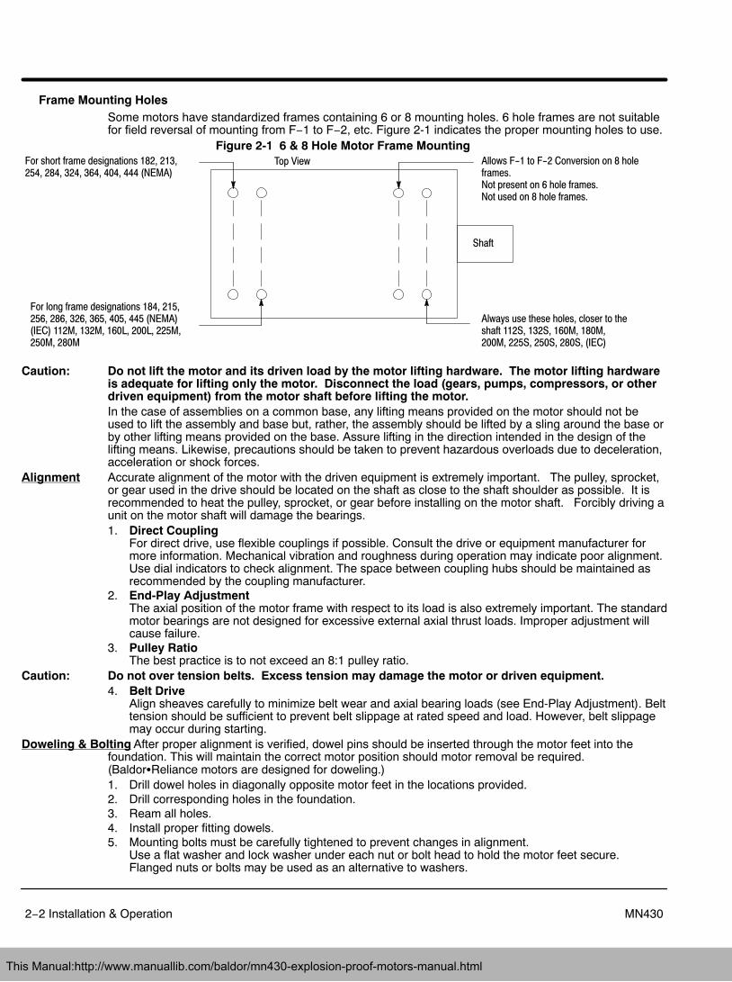
Frame Mounting HolesSome motors have standardized frames containing 6 or 8 mounting holes. 6 hole frames are not suitablefor field reversal of mounting from F−1 to F−2, etc. Figure 2-1 indicates the proper mounting holes to use.
Figure 2-1 6 & 8 Hole Motor Frame Mounting Top View Allows F-1 to F-2 Conversion on 8 hole
frames.Not present on 6 hole frames.Not used on 8 hole frames.
Shaft
Always use these holes, closer to theshaft 112S, 132S, 160M, 180M,200M, 225S, 250S, 280S, (IEC)
For short frame designations 182, 213, 254, 284, 324, 364, 404, 444 (NEMA)
For long frame designations 184, 215, 256, 286, 326, 365, 405, 445 (NEMA)(IEC) 112M, 132M, 160L, 200L, 225M,250M, 280M
Caution: Do not lift the motor and its driven load by the motor lifting hardware. The motor lifting hardwareis adequate for lifting only the motor. Disconnect the load (gears, pumps, compressors, or otherdriven equipment) from the motor shaft before lifting the motor.In the case of assemblies on a common base, any lifting means provided on the motor should not beused to lift the assembly and base but, rather, the assembly should be lifted by a sling around the base orby other lifting means provided on the base. Assure lifting in the direction intended in the design of thelifting means. Likewise, precautions should be taken to prevent hazardous overloads due to deceleration,acceleration or shock forces.
Alignment Accurate alignment of the motor with the driven equipment is extremely important. The pulley, sprocket,or gear used in the drive should be located on the shaft as close to the shaft shoulder as possible. It isrecommended to heat the pulley, sprocket, or gear before installing on the motor shaft. Forcibly driving aunit on the motor shaft will damage the bearings.1. Direct Coupling
For direct drive, use flexible couplings if possible. Consult the drive or equipment manufacturer formore information. Mechanical vibration and roughness during operation may indicate poor alignment.Use dial indicators to check alignment. The space between coupling hubs should be maintained asrecommended by the coupling manufacturer.
2. End-Play AdjustmentThe axial position of the motor frame with respect to its load is also extremely important. The standardmotor bearings are not designed for excessive external axial thrust loads. Improper adjustment willcause failure.
3. Pulley RatioThe best practice is to not exceed an 8:1 pulley ratio.
Caution: Do not over tension belts. Excess tension may damage the motor or driven equipment.4. Belt Drive
Align sheaves carefully to minimize belt wear and axial bearing loads (see End-Play Adjustment). Belttension should be sufficient to prevent belt slippage at rated speed and load. However, belt slippagemay occur during starting.
Doweling & Bolting After proper alignment is verified, dowel pins should be inserted through the motor feet into thefoundation. This will maintain the correct motor position should motor removal be required.(Baldor�Reliance motors are designed for doweling.)1. Drill dowel holes in diagonally opposite motor feet in the locations provided.2. Drill corresponding holes in the foundation.3. Ream all holes.4. Install proper fitting dowels.5. Mounting bolts must be carefully tightened to prevent changes in alignment.
Use a flat washer and lock washer under each nut or bolt head to hold the motor feet secure. Flanged nuts or bolts may be used as an alternative to washers.
This Manual:http://www.manuallib.com/baldor/mn430-explosion-proof-motors-manual.html
Installation & Operation 2−3MN430
WARNING: Guards must be installed for rotating parts such as couplings, pulleys, external fans, and unusedshaft extensions, should be permanently guarded to prevent accidental contact by personnel.Accidental contact with body parts or clothing can cause serious or fatal injury.
Guarding Guards must be installed for rotating parts such as couplings, pulleys, external fans, and unused shaftextensions. This is particularly important where the parts have surface irregularities such as keys, keyways or set screws. Some satisfactory methods of guarding are:1. Covering the machine and associated rotating parts with structural or decorative parts of the driven
equipment.2. Providing covers for the rotating parts. Covers should be sufficiently rigid to maintain adequate
guarding during normal service.Connection of AC Power Supply
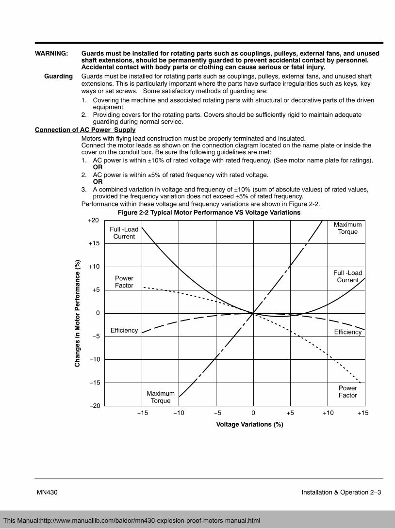
Motors with flying lead construction must be properly terminated and insulated.Connect the motor leads as shown on the connection diagram located on the name plate or inside thecover on the conduit box. Be sure the following guidelines are met:1. AC power is within 10% of rated voltage with rated frequency. (See motor name plate for ratings).
OR2. AC power is within 5% of rated frequency with rated voltage.
OR3. A combined variation in voltage and frequency of 10% (sum of absolute values) of rated values,
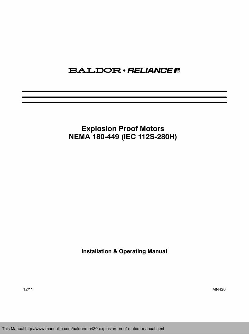
provided the frequency variation does not exceed 5% of rated frequency.Performance within these voltage and frequency variations are shown in Figure 2-2.
Figure 2-2 Typical Motor Performance VS Voltage Variations+20
+15
+10
+5
0
−5
−10
−15
−20−15 −10 −5 0 +5 +10 +15
Voltage Variations (%)
Ch
ang
es in
Mo
tor
Per
form
ance
(%
)
Full -LoadCurrent
Full -LoadCurrentPower
Factor
PowerFactor
Efficiency Efficiency
MaximumTorque
MaximumTorque
This Manual:http://www.manuallib.com/baldor/mn430-explosion-proof-motors-manual.html
2−4 Installation & Operation MN430
Connection of Additional Devices
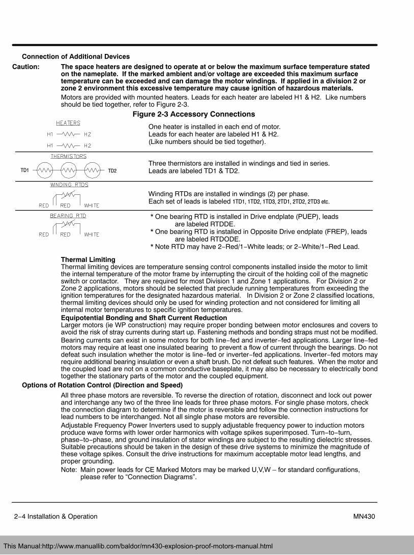
Caution: The space heaters are designed to operate at or below the maximum surface temperature statedon the nameplate. If the marked ambient and/or voltage are exceeded this maximum surfacetemperature can be exceeded and can damage the motor windings. If applied in a division 2 orzone 2 environment this excessive temperature may cause ignition of hazardous materials.Motors are provided with mounted heaters. Leads for each heater are labeled H1 & H2. Like numbersshould be tied together, refer to Figure 2-3.
Figure 2-3 Accessory Connections
One heater is installed in each end of motor. Leads for each heater are labeled H1 & H2. (Like numbers should be tied together).
Three thermistors are installed in windings and tied in series.Leads are labeled TD1 & TD2.
Winding RTDs are installed in windings (2) per phase. Each set of leads is labeled 1TD1, 1TD2, 1TD3, 2TD1, 2TD2, 2TD3 etc.
* One bearing RTD is installed in Drive endplate (PUEP), leads are labeled RTDDE.
* One bearing RTD is installed in Opposite Drive endplate (FREP), leads are labeled RTDODE.
* Note RTD may have 2−Red/1−White leads; or 2−White/1−Red Lead.
TD1 TD2
Thermal Limiting Thermal limiting devices are temperature sensing control components installed inside the motor to limitthe internal temperature of the motor frame by interrupting the circuit of the holding coil of the magneticswitch or contactor. They are required for most Division 1 and Zone 1 applications. For Division 2 orZone 2 applications, motors should be selected that preclude running temperatures from exceeding theignition temperatures for the designated hazardous material. In Division 2 or Zone 2 classified locations,thermal limiting devices should only be used for winding protection and not considered for limiting allinternal motor temperatures to specific ignition temperatures.Equipotential Bonding and Shaft Current ReductionLarger motors (ie WP construction) may require proper bonding between motor enclosures and covers toavoid the risk of stray currents during start up. Fastening methods and bonding straps must not be modified.Bearing currents can exist in some motors for both line−fed and inverter−fed applications. Larger line−fedmotors may require at least one insulated bearing to prevent a flow of current through the bearings. Do notdefeat such insulation whether the motor is line−fed or inverter−fed applications. Inverter−fed motors mayrequire additional bearing insulation or even a shaft brush. Do not defeat such features. When the motor andthe coupled load are not on a common conductive baseplate, it may also be necessary to electrically bondtogether the stationary parts of the motor and the coupled equipment.
Options of Rotation Control (Direction and Speed)
All three phase motors are reversible. To reverse the direction of rotation, disconnect and lock out powerand interchange any two of the three line leads for three phase motors. For single phase motors, checkthe connection diagram to determine if the motor is reversible and follow the connection instructions forlead numbers to be interchanged. Not all single phase motors are reversible.Adjustable Frequency Power Inverters used to supply adjustable frequency power to induction motorsproduce wave forms with lower order harmonics with voltage spikes superimposed. Turn−to−turn,phase−to−phase, and ground insulation of stator windings are subject to the resulting dielectric stresses.Suitable precautions should be taken in the design of these drive systems to minimize the magnitude ofthese voltage spikes. Consult the drive instructions for maximum acceptable motor lead lengths, andproper grounding.Note: Main power leads for CE Marked Motors may be marked U,V,W – for standard configurations,
please refer to “Connection Diagrams”.
This Manual:http://www.manuallib.com/baldor/mn430-explosion-proof-motors-manual.html
Installation & Operation 2−5MN430
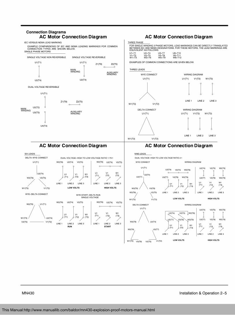
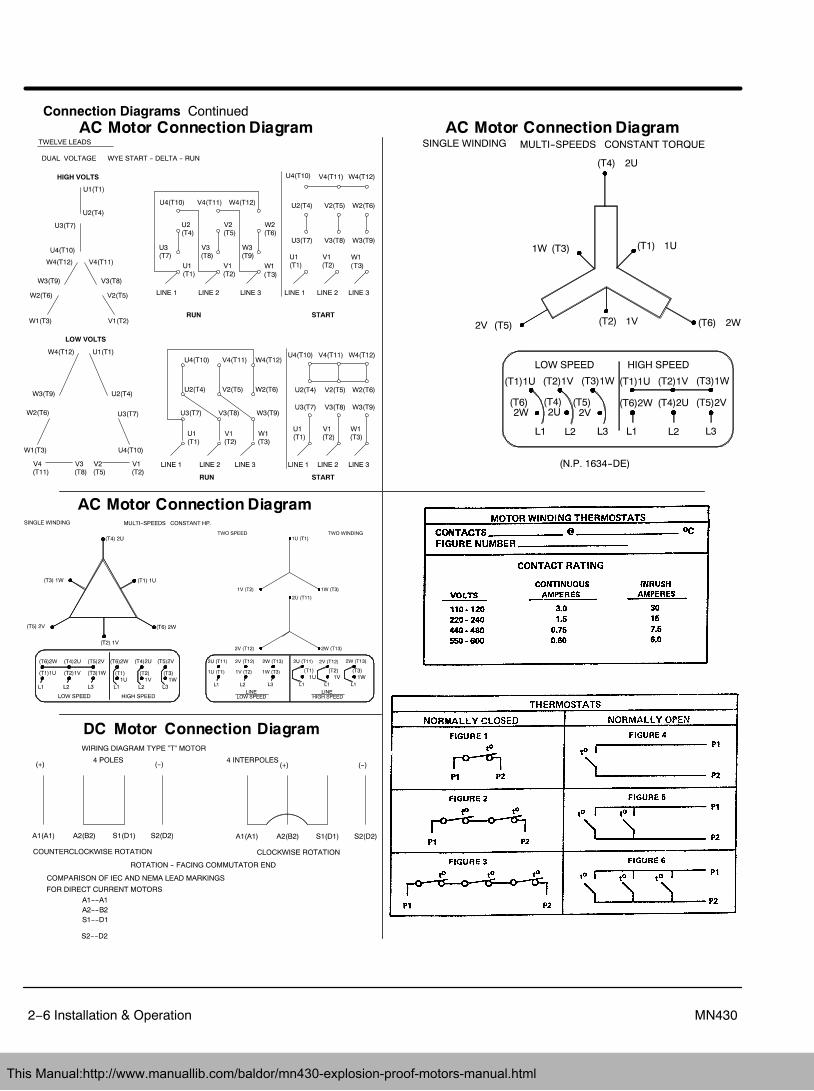
Connection Diagrams
This Manual:http://www.manuallib.com/baldor/mn430-explosion-proof-motors-manual.html
2−6 Installation & Operation MN430
Connection Diagrams Continued
This Manual:http://www.manuallib.com/baldor/mn430-explosion-proof-motors-manual.html
Installation & Operation 2−7MN430
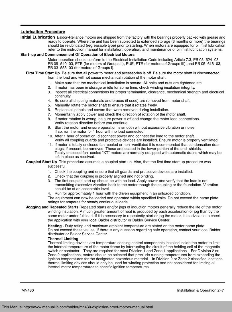
Lubrication ProcedureInitial Lubrication Baldor�Reliance motors are shipped from the factory with the bearings properly packed with grease and
ready to operate. Where the unit has been subjected to extended storage (6 months or more) the bearingsshould be relubricated (regreasable type) prior to starting. When motors are equipped for oil mist lubricationrefer to the instruction manual for installation, operation, and maintenance of oil mist lubrication systems.
Start−up and Commencement Of Operation of Electrical MotorsMotor operation should conform to the Electrical Installation Code including Article 7.3, PB 08−624−03,PB 09−540−03, PTE (for motors of Groups II), PUE, PTE (for motors of Groups III), and PB 05−618−03,PB 03−553−03 (for motors of Groups I).
First Time Start Up Be sure that all power to motor and accessories is off. Be sure the motor shaft is disconnectedfrom the load and will not cause mechanical rotation of the motor shaft.1. Make sure that the mechanical installation is secure. All bolts and nuts are tightened etc.2. If motor has been in storage or idle for some time, check winding insulation integrity.3. Inspect all electrical connections for proper termination, clearance, mechanical strength and electrical
continuity.4. Be sure all shipping materials and braces (if used) are removed from motor shaft.5. Manually rotate the motor shaft to ensure that it rotates freely.6. Replace all panels and covers that were removed during installation.7. Momentarily apply power and check the direction of rotation of the motor shaft.8. If motor rotation is wrong, be sure power is off and change the motor lead connections.
Verify rotation direction before you continue.9. Start the motor and ensure operation is smooth without excessive vibration or noise.
If so, run the motor for 1 hour with no load connected.10. After 1 hour of operation, disconnect power and connect the load to the motor shaft.
Verify all coupling guards and protective devices are installed. Ensure motor is properly ventilated.11. If motor is totally enclosed fan−cooled or non−ventilated it is recommended that condensation drain
plugs, if present, be removed. These are located in the lower portion of the end−shields. Totally enclosed fan−cooled “XT” motors are normally equipped with automatic drains which may beleft in place as received.
Coupled Start Up This procedure assumes a coupled start up. Also, that the first time start up procedure wassuccessful.1. Check the coupling and ensure that all guards and protective devices are installed.2. Check that the coupling is properly aligned and not binding.3. The first coupled start up should be with no load. Apply power and verify that the load is not
transmitting excessive vibration back to the motor though the coupling or the foundation. Vibrationshould be at an acceptable level.
4. Run for approximately 1 hour with the driven equipment in an unloaded condition.The equipment can now be loaded and operated within specified limits. Do not exceed the name plateratings for amperes for steady continuous loads.
Jogging and Repeated Starts Repeated starts and/or jogs of induction motors generally reduce the life of the motorwinding insulation. A much greater amount of heat is produced by each acceleration or jog than by thesame motor under full load. If it is necessary to repeatedly start or jog the motor, it is advisable to checkthe application with your local Baldor distributor or Baldor Service Center.
Heating - Duty rating and maximum ambient temperature are stated on the motor name plate. Do not exceed these values. If there is any question regarding safe operation, contact your local Baldordistributor or Baldor Service Center.Thermal Limiting Thermal limiting devices are temperature sensing control components installed inside the motor to limitthe internal temperature of the motor frame by interrupting the circuit of the holding coil of the magneticswitch or contactor. They are required for most Division 1 and Zone 1 applications. For Division 2 orZone 2 applications, motors should be selected that preclude running temperatures from exceeding theignition temperatures for the designated hazardous material. In Division 2 or Zone 2 classified locations,thermal limiting devices should only be used for winding protection and not considered for limiting allinternal motor temperatures to specific ignition temperatures.
This Manual:http://www.manuallib.com/baldor/mn430-explosion-proof-motors-manual.html
2−8 Installation & Operation MN430
RepairRepair of hazardous certified motors requires additional information, skill, and care. It is the customer’sresponsibility to select service shops with proper qualifications to repair hazardous location motors.Contact the manufacture for additional repair details. Use only original manufacturer’s parts.
This Manual:http://www.manuallib.com/baldor/mn430-explosion-proof-motors-manual.html
Section 3Maintenance & Troubleshooting
Maintenance & Troubleshooting 3−1MN430
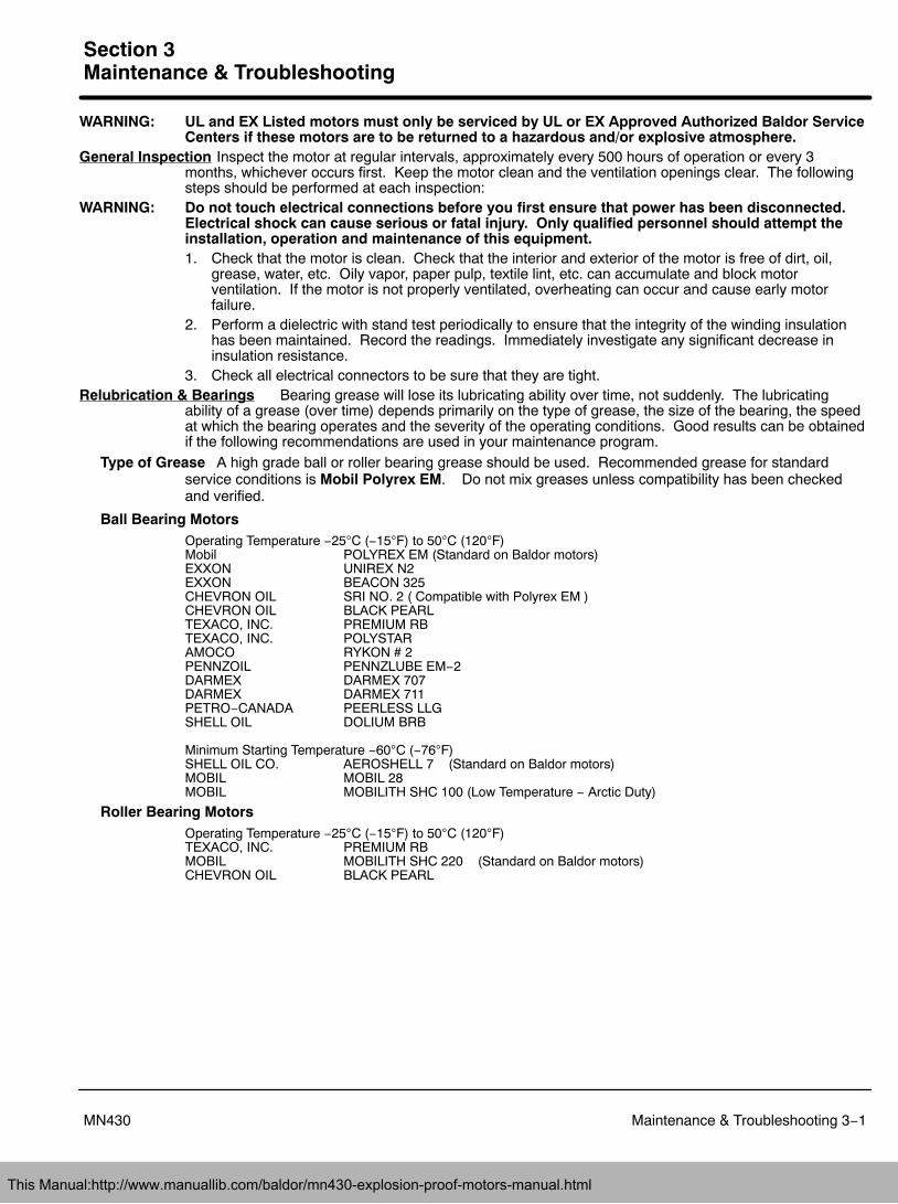
WARNING: UL and EX Listed motors must only be serviced by UL or EX Approved Authorized Baldor ServiceCenters if these motors are to be returned to a hazardous and/or explosive atmosphere.
General Inspection Inspect the motor at regular intervals, approximately every 500 hours of operation or every 3months, whichever occurs first. Keep the motor clean and the ventilation openings clear. The followingsteps should be performed at each inspection:
WARNING: Do not touch electrical connections before you first ensure that power has been disconnected.Electrical shock can cause serious or fatal injury. Only qualified personnel should attempt theinstallation, operation and maintenance of this equipment.1. Check that the motor is clean. Check that the interior and exterior of the motor is free of dirt, oil,
grease, water, etc. Oily vapor, paper pulp, textile lint, etc. can accumulate and block motorventilation. If the motor is not properly ventilated, overheating can occur and cause early motorfailure.
2. Perform a dielectric with stand test periodically to ensure that the integrity of the winding insulationhas been maintained. Record the readings. Immediately investigate any significant decrease ininsulation resistance.
3. Check all electrical connectors to be sure that they are tight.Relubrication & Bearings Bearing grease will lose its lubricating ability over time, not suddenly. The lubricating
ability of a grease (over time) depends primarily on the type of grease, the size of the bearing, the speedat which the bearing operates and the severity of the operating conditions. Good results can be obtainedif the following recommendations are used in your maintenance program.
Type of Grease A high grade ball or roller bearing grease should be used. Recommended grease for standardservice conditions is Mobil Polyrex EM. Do not mix greases unless compatibility has been checkedand verified.
Ball Bearing MotorsOperating Temperature −25C (−15F) to 50C (120F)Mobil POLYREX EM (Standard on Baldor motors)EXXON UNIREX N2EXXON BEACON 325CHEVRON OIL SRI NO. 2 ( Compatible with Polyrex EM )CHEVRON OIL BLACK PEARLTEXACO, INC. PREMIUM RBTEXACO, INC. POLYSTARAMOCO RYKON # 2PENNZOIL PENNZLUBE EM−2DARMEX DARMEX 707DARMEX DARMEX 711PETRO−CANADA PEERLESS LLGSHELL OIL DOLIUM BRB
Minimum Starting Temperature −60C (−76F)SHELL OIL CO. AEROSHELL 7 (Standard on Baldor motors)MOBIL MOBIL 28MOBIL MOBILITH SHC 100 (Low Temperature − Arctic Duty)
Roller Bearing MotorsOperating Temperature −25C (−15F) to 50C (120F)TEXACO, INC. PREMIUM RBMOBIL MOBILITH SHC 220 (Standard on Baldor motors)CHEVRON OIL BLACK PEARL
This Manual:http://www.manuallib.com/baldor/mn430-explosion-proof-motors-manual.html
3−2 Maintenance & Troubleshooting MN430
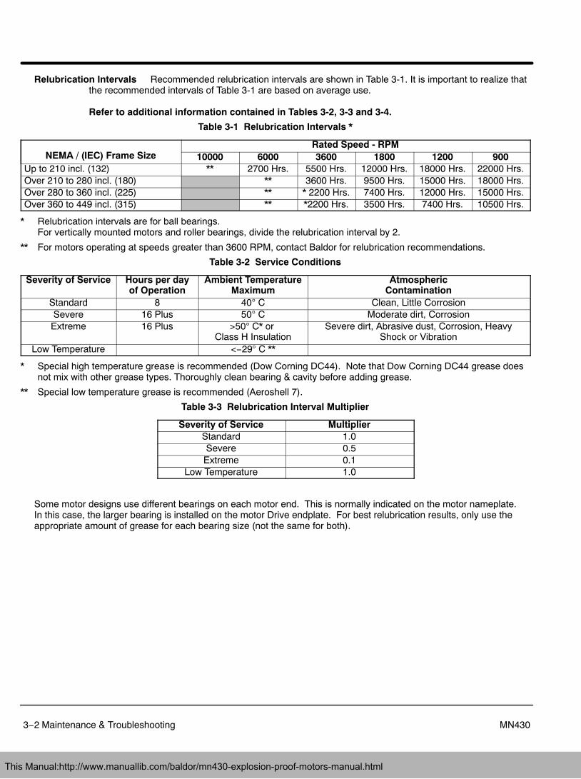
Relubrication Intervals Recommended relubrication intervals are shown in Table 3-1. It is important to realize thatthe recommended intervals of Table 3-1 are based on average use.
Refer to additional information contained in Tables 3-2, 3-3 and 3-4.
Table 3-1 Relubrication Intervals *
NEMA / (IEC) Frame SizeRated Speed - RPM
10000 6000 3600 1800 1200 900Up to 210 incl. (132) ** 2700 Hrs. 5500 Hrs. 12000 Hrs. 18000 Hrs. 22000 Hrs.Over 210 to 280 incl. (180) ** 3600 Hrs. 9500 Hrs. 15000 Hrs. 18000 Hrs.Over 280 to 360 incl. (225) ** * 2200 Hrs. 7400 Hrs. 12000 Hrs. 15000 Hrs.Over 360 to 449 incl. (315) ** *2200 Hrs. 3500 Hrs. 7400 Hrs. 10500 Hrs.
* Relubrication intervals are for ball bearings. For vertically mounted motors and roller bearings, divide the relubrication interval by 2.
** For motors operating at speeds greater than 3600 RPM, contact Baldor for relubrication recommendations.
Table 3-2 Service Conditions
Severity of Service Hours per dayof Operation
Ambient TemperatureMaximum
AtmosphericContamination
Standard 8 40 C Clean, Little CorrosionSevere 16 Plus 50 C Moderate dirt, CorrosionExtreme 16 Plus >50 C* or
Class H InsulationSevere dirt, Abrasive dust, Corrosion, Heavy
Shock or VibrationLow Temperature <−29 C **
* Special high temperature grease is recommended (Dow Corning DC44). Note that Dow Corning DC44 grease doesnot mix with other grease types. Thoroughly clean bearing & cavity before adding grease.
** Special low temperature grease is recommended (Aeroshell 7).
Table 3-3 Relubrication Interval Multiplier
Severity of Service MultiplierStandard 1.0Severe 0.5Extreme 0.1
Low Temperature 1.0
Some motor designs use different bearings on each motor end. This is normally indicated on the motor nameplate. In this case, the larger bearing is installed on the motor Drive endplate. For best relubrication results, only use theappropriate amount of grease for each bearing size (not the same for both).
This Manual:http://www.manuallib.com/baldor/mn430-explosion-proof-motors-manual.html
Maintenance & Troubleshooting 3−3MN430
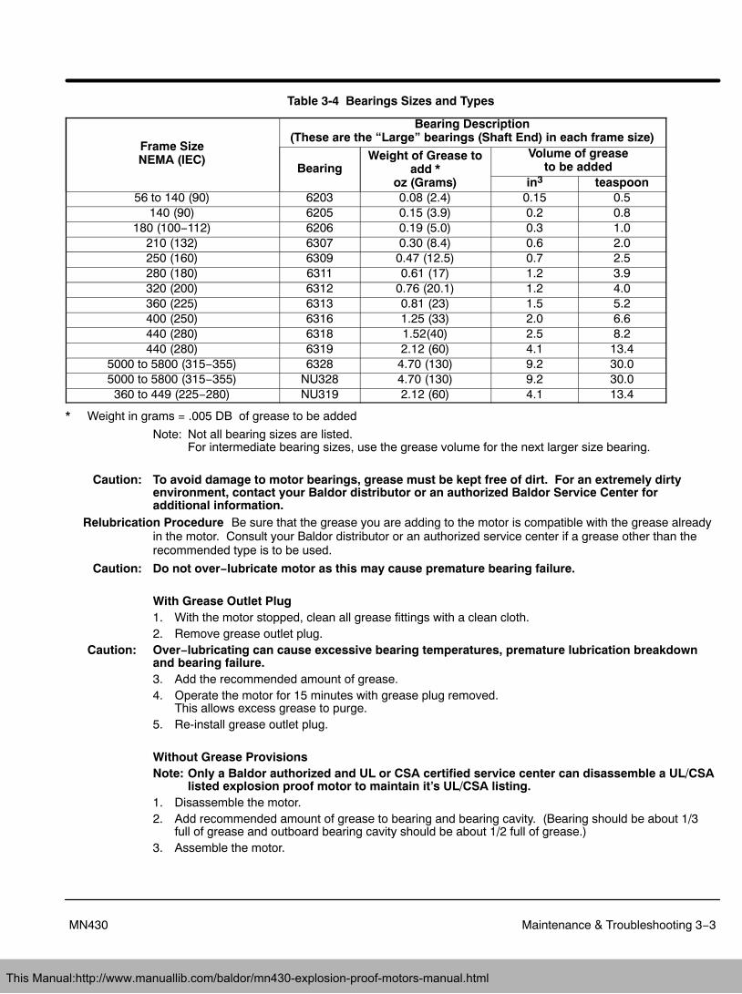
Table 3-4 Bearings Sizes and Types
Frame SizeNEMA (IEC)
Bearing Description(These are the “Large” bearings (Shaft End) in each frame size)
BearingWeight of Grease to
add *oz (Grams)
Volume of greaseto be added
in3 teaspoon56 to 140 (90) 6203 0.08 (2.4) 0.15 0.5
140 (90) 6205 0.15 (3.9) 0.2 0.8180 (100−112) 6206 0.19 (5.0) 0.3 1.0
210 (132) 6307 0.30 (8.4) 0.6 2.0250 (160) 6309 0.47 (12.5) 0.7 2.5280 (180) 6311 0.61 (17) 1.2 3.9320 (200) 6312 0.76 (20.1) 1.2 4.0360 (225) 6313 0.81 (23) 1.5 5.2400 (250) 6316 1.25 (33) 2.0 6.6440 (280) 6318 1.52(40) 2.5 8.2440 (280) 6319 2.12 (60) 4.1 13.4
5000 to 5800 (315−355) 6328 4.70 (130) 9.2 30.05000 to 5800 (315−355) NU328 4.70 (130) 9.2 30.0360 to 449 (225−280) NU319 2.12 (60) 4.1 13.4
* Weight in grams = .005 DB of grease to be added
Note: Not all bearing sizes are listed. For intermediate bearing sizes, use the grease volume for the next larger size bearing.
Caution: To avoid damage to motor bearings, grease must be kept free of dirt. For an extremely dirtyenvironment, contact your Baldor distributor or an authorized Baldor Service Center foradditional information.
Relubrication Procedure Be sure that the grease you are adding to the motor is compatible with the grease alreadyin the motor. Consult your Baldor distributor or an authorized service center if a grease other than therecommended type is to be used.
Caution: Do not over−lubricate motor as this may cause premature bearing failure.
With Grease Outlet Plug1. With the motor stopped, clean all grease fittings with a clean cloth.2. Remove grease outlet plug.
Caution: Over−lubricating can cause excessive bearing temperatures, premature lubrication breakdownand bearing failure.3. Add the recommended amount of grease.4. Operate the motor for 15 minutes with grease plug removed.
This allows excess grease to purge.5. Re-install grease outlet plug.
Without Grease ProvisionsNote: Only a Baldor authorized and UL or CSA certified service center can disassemble a UL/CSA
listed explosion proof motor to maintain it’s UL/CSA listing.1. Disassemble the motor.2. Add recommended amount of grease to bearing and bearing cavity. (Bearing should be about 1/3
full of grease and outboard bearing cavity should be about 1/2 full of grease.)3. Assemble the motor.
This Manual:http://www.manuallib.com/baldor/mn430-explosion-proof-motors-manual.html
3−4 Maintenance & Troubleshooting MN430
Sample Relubrication Determination
Assume - NEMA 286T (IEC 180), 1750 RPM motor driving an exhaust fan in an ambient temperature of43 C and the atmosphere is moderately corrosive.1. Table 3-1 list 9500 hours for standard conditions.2. Table 3-2 classifies severity of service as “Severe”.3. Table 3-4 shows that 1.2 in3 or 3.9 teaspoon of grease is to be added.Note: Smaller bearings in size category may require reduced amounts of grease.
This Manual:http://www.manuallib.com/baldor/mn430-explosion-proof-motors-manual.html
Section 1General Information
Maintenance & Troubleshooting 3−5MN430
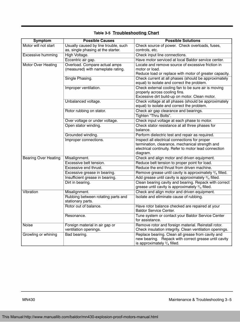
Table 3-5 Troubleshooting Chart
Symptom Possible Causes Possible SolutionsMotor will not start Usually caused by line trouble, such
as, single phasing at the starter.Check source of power. Check overloads, fuses,controls, etc.
Excessive humming High Voltage. Check input line connections.Eccentric air gap. Have motor serviced at local Baldor service center.
Motor Over Heating Overload. Compare actual amps(measured) with nameplate rating.
Locate and remove source of excessive friction inmotor or load.Reduce load or replace with motor of greater capacity.
Single Phasing. Check current at all phases (should be approximatelyequal) to isolate and correct the problem.
Improper ventilation. Check external cooling fan to be sure air is movingproperly across cooling fins.Excessive dirt build-up on motor. Clean motor.
Unbalanced voltage. Check voltage at all phases (should be approximatelyequal) to isolate and correct the problem.
Rotor rubbing on stator. Check air gap clearance and bearings.Tighten “Thru Bolts”.
Over voltage or under voltage. Check input voltage at each phase to motor.Open stator winding. Check stator resistance at all three phases for
balance.Grounded winding. Perform dielectric test and repair as required.Improper connections. Inspect all electrical connections for proper
termination, clearance, mechanical strength andelectrical continuity. Refer to motor lead connectiondiagram.
Bearing Over Heating Misalignment. Check and align motor and driven equipment.Excessive belt tension. Reduce belt tension to proper point for load.Excessive end thrust. Reduce the end thrust from driven machine.Excessive grease in bearing. Remove grease until cavity is approximately 3/4 filled.Insufficient grease in bearing. Add grease until cavity is approximately 3/4 filled.Dirt in bearing. Clean bearing cavity and bearing. Repack with correct
grease until cavity is approximately 3/4 filled.Vibration Misalignment. Check and align motor and driven equipment.
Rubbing between rotating parts andstationary parts.
Isolate and eliminate cause of rubbing.
Rotor out of balance. Have rotor balance checked are repaired at yourBaldor Service Center.
Resonance. Tune system or contact your Baldor Service Centerfor assistance.
Noise Foreign material in air gap orventilation openings.
Remove rotor and foreign material. Reinstall rotor.Check insulation integrity. Clean ventilation openings.
Growling or whining Bad bearing. Replace bearing. Clean all grease from cavity andnew bearing. Repack with correct grease until cavityis approximately 3/4 filled.
This Manual:http://www.manuallib.com/baldor/mn430-explosion-proof-motors-manual.html
3−6 Maintenance & Troubleshooting MN430
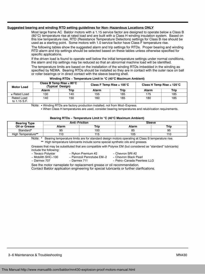
Suggested bearing and winding RTD setting guidelines for Non−Hazardous Locations ONLYMost large frame AC Baldor motors with a 1.15 service factor are designed to operate below a Class B(80C) temperature rise at rated load and are built with a Class H winding insulation system. Based onthis low temperature rise, RTD (Resistance Temperature Detectors) settings for Class B rise should beused as a starting point. Some motors with 1.0 service factor have Class F temperature rise.The following tables show the suggested alarm and trip settings for RTDs. Proper bearing and windingRTD alarm and trip settings should be selected based on these tables unless otherwise specified forspecific applications.If the driven load is found to operate well below the initial temperature settings under normal conditions,the alarm and trip settings may be reduced so that an abnormal machine load will be identified.The temperature limits are based on the installation of the winding RTDs imbedded in the winding asspecified by NEMA. Bearing RTDs should be installed so they are in contact with the outer race on ballor roller bearings or in direct contact with the sleeve bearing shell.
Winding RTDs − Temperature Limit In �C (40�C Maximum Ambient)
Motor LoadClass B Temp Rise � 80C
(Typical Design) Class F Temp Rise � 105C Class H Temp Rise � 125C
Alarm Trip Alarm Trip Alarm Trip� Rated Load 130 140 155 165 175 185Rated Load to 1.15 S.F.
140 150 160 165 180 185
Note: � Winding RTDs are factory production installed, not from Mod−Express.� When Class H temperatures are used, consider bearing temperatures and relubrication requirements.
Bearing RTDs − Temperature Limit In �C (40�C Maximum Ambient)
Bearing TypeOil or Grease
Anti−Friction SleeveAlarm Trip Alarm Trip
Standard* 95 100 85 95High Temperature** 110 115 105 110
Note: * Bearing temperature limits are for standard design motors operating at Class B temperature rise.** High temperature lubricants include some special synthetic oils and greases.
Greases that may be substituted that are compatible with Polyrex EM (but considered as “standard” lubricants)include the following: − Texaco Polystar − Rykon Premium #2 − Chevron SRI #2− Mobilith SHC−100 − Pennzoil Pennzlube EM−2 − Chevron Black Pearl− Darmex 707 − Darmex 711 − Petro−Canada Peerless LLG
See the motor nameplate for replacement grease or oil recommendation. Contact Baldor application engineering for special lubricants or further clarifications.
This Manual:http://www.manuallib.com/baldor/mn430-explosion-proof-motors-manual.html
Appendix A
A−1MN430
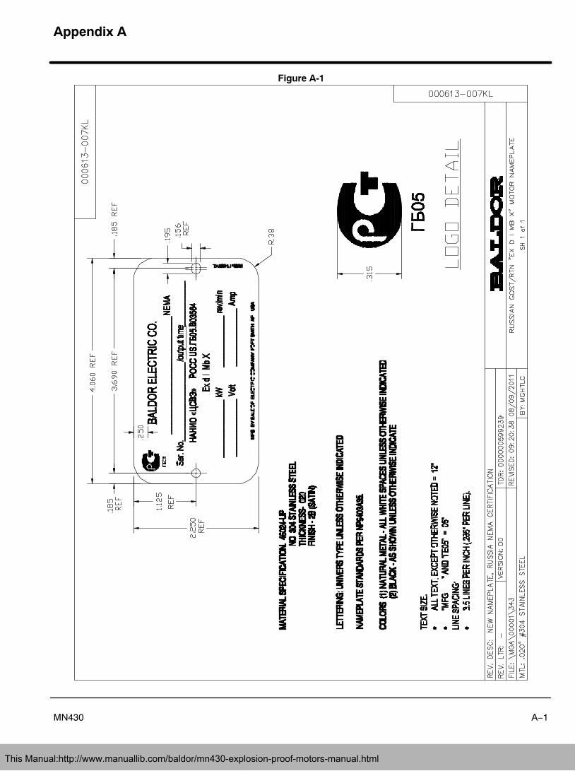
Figure A-1
This Manual:http://www.manuallib.com/baldor/mn430-explosion-proof-motors-manual.html
A−2 MN430
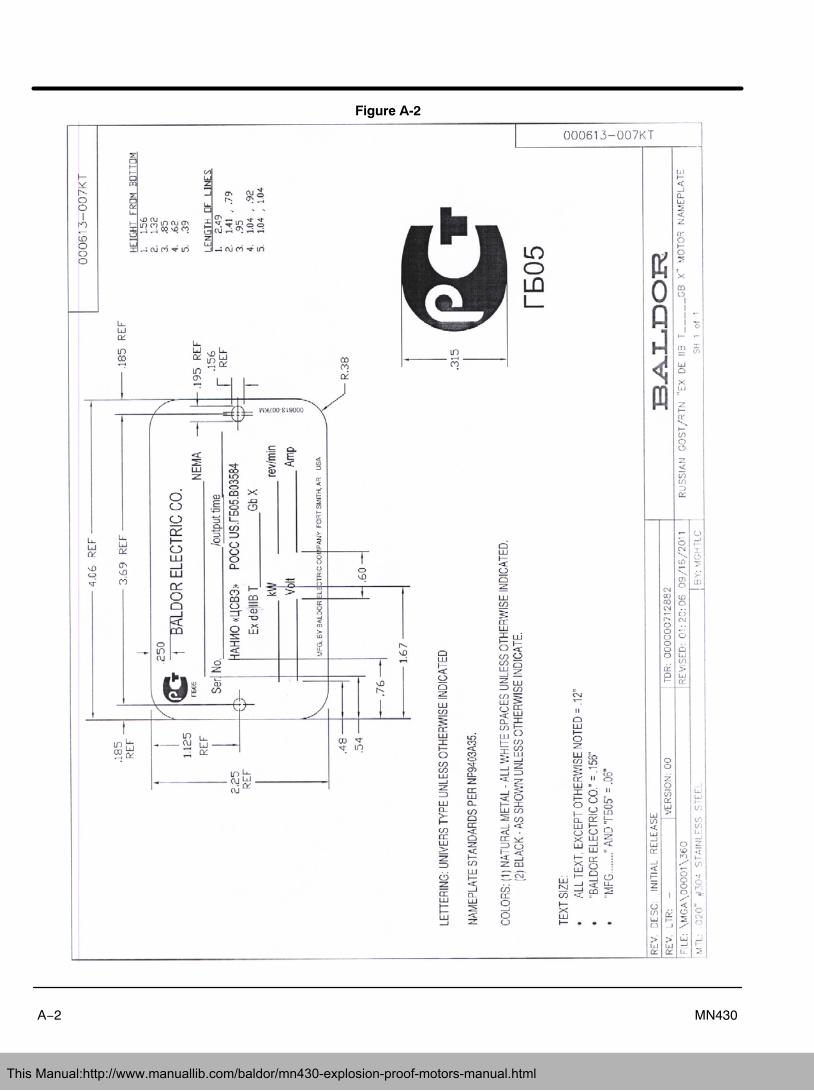
Figure A-2
This Manual:http://www.manuallib.com/baldor/mn430-explosion-proof-motors-manual.html
A−3MN430
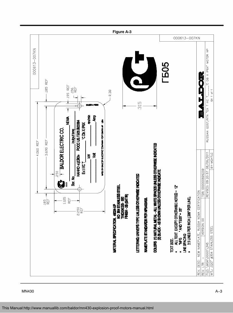
Figure A-3
This Manual:http://www.manuallib.com/baldor/mn430-explosion-proof-motors-manual.html
A−4 MN430
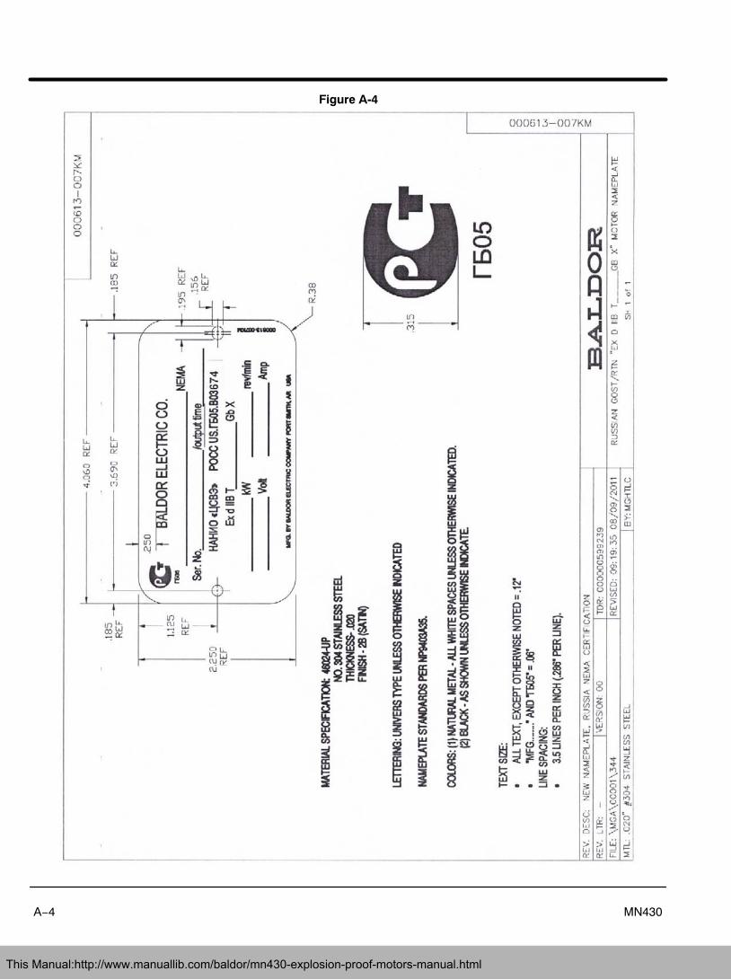
Figure A-4
This Manual:http://www.manuallib.com/baldor/mn430-explosion-proof-motors-manual.html
A−5MN430
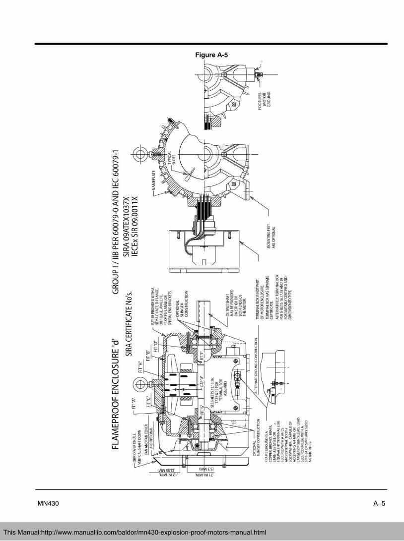
Figure A-5
This Manual:http://www.manuallib.com/baldor/mn430-explosion-proof-motors-manual.html

A−6 MN430
This Manual:http://www.manuallib.com/baldor/mn430-explosion-proof-motors-manual.html
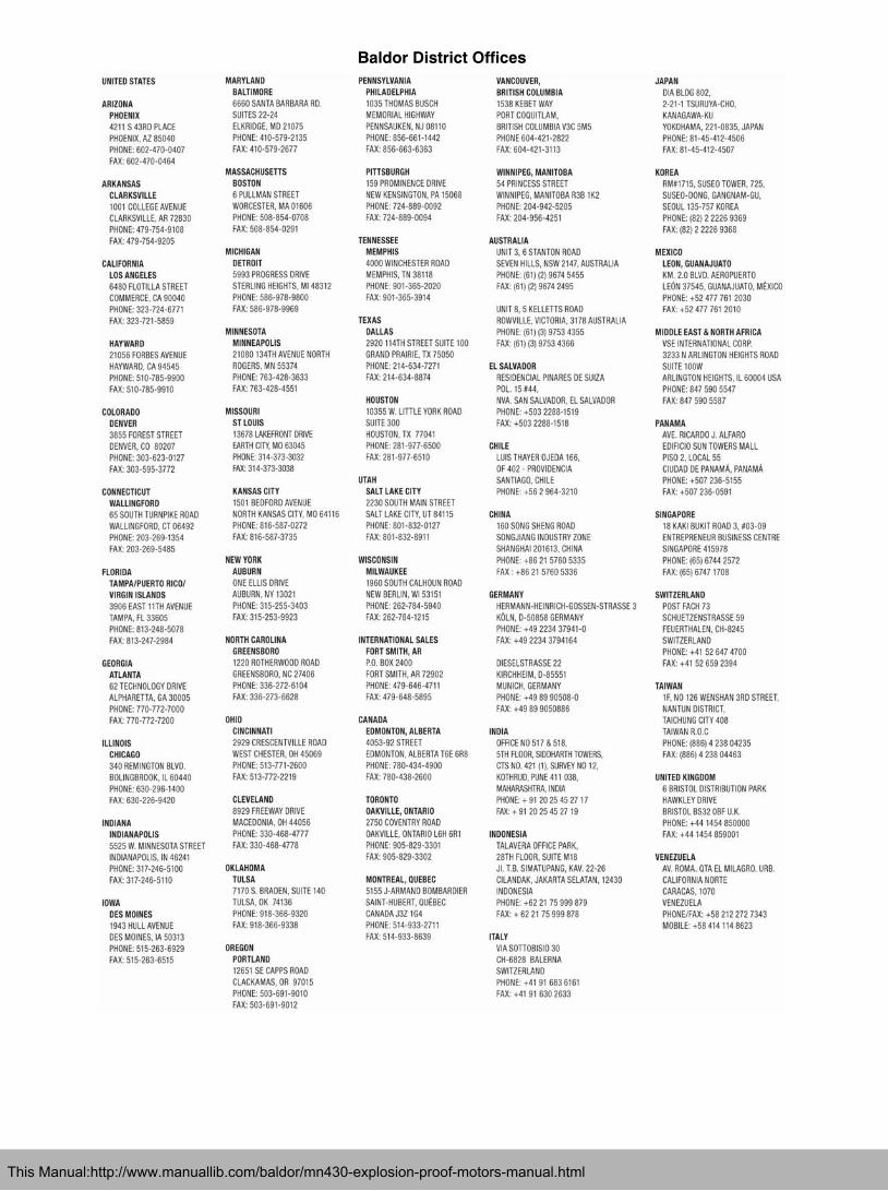
Baldor District Offices
This Manual:http://www.manuallib.com/baldor/mn430-explosion-proof-motors-manual.html
2011 Baldor Electric CompanyMN430
All rights reserved. Printed in USA12/11
BALDOR ELECTRIC COMPANYP.O. Box 2400 Fort Smith, AR 72901−2400
(479) 646−4711 Fax (479) 648−5792www.baldor.com
This Manual:http://www.manuallib.com/baldor/mn430-explosion-proof-motors-manual.html